EP3466230A1 - Work device, work vehicle, work machine, and management system - Google Patents
Work device, work vehicle, work machine, and management system Download PDFInfo
- Publication number
- EP3466230A1 EP3466230A1 EP17861132.3A EP17861132A EP3466230A1 EP 3466230 A1 EP3466230 A1 EP 3466230A1 EP 17861132 A EP17861132 A EP 17861132A EP 3466230 A1 EP3466230 A1 EP 3466230A1
- Authority
- EP
- European Patent Office
- Prior art keywords
- identifying information
- information
- working device
- working
- wireless tag
- Prior art date
- Legal status (The legal status is an assumption and is not a legal conclusion. Google has not performed a legal analysis and makes no representation as to the accuracy of the status listed.)
- Granted
Links
Images








Classifications
-
- G—PHYSICS
- G06—COMPUTING OR CALCULATING; COUNTING
- G06K—GRAPHICAL DATA READING; PRESENTATION OF DATA; RECORD CARRIERS; HANDLING RECORD CARRIERS
- G06K19/00—Record carriers for use with machines and with at least a part designed to carry digital markings
- G06K19/06—Record carriers for use with machines and with at least a part designed to carry digital markings characterised by the kind of the digital marking, e.g. shape, nature, code
- G06K19/08—Record carriers for use with machines and with at least a part designed to carry digital markings characterised by the kind of the digital marking, e.g. shape, nature, code using markings of different kinds or more than one marking of the same kind in the same record carrier, e.g. one marking being sensed by optical and the other by magnetic means
-
- A—HUMAN NECESSITIES
- A01—AGRICULTURE; FORESTRY; ANIMAL HUSBANDRY; HUNTING; TRAPPING; FISHING
- A01B—SOIL WORKING IN AGRICULTURE OR FORESTRY; PARTS, DETAILS, OR ACCESSORIES OF AGRICULTURAL MACHINES OR IMPLEMENTS, IN GENERAL
- A01B59/00—Devices specially adapted for connection between animals or tractors and agricultural machines or implements
-
- A—HUMAN NECESSITIES
- A01—AGRICULTURE; FORESTRY; ANIMAL HUSBANDRY; HUNTING; TRAPPING; FISHING
- A01B—SOIL WORKING IN AGRICULTURE OR FORESTRY; PARTS, DETAILS, OR ACCESSORIES OF AGRICULTURAL MACHINES OR IMPLEMENTS, IN GENERAL
- A01B63/00—Lifting or adjusting devices or arrangements for agricultural machines or implements
- A01B63/02—Lifting or adjusting devices or arrangements for agricultural machines or implements for implements mounted on tractors
- A01B63/10—Lifting or adjusting devices or arrangements for agricultural machines or implements for implements mounted on tractors operated by hydraulic or pneumatic means
- A01B63/102—Lifting or adjusting devices or arrangements for agricultural machines or implements for implements mounted on tractors operated by hydraulic or pneumatic means characterised by the location of the mounting on the tractor, e.g. on the rear part
-
- A—HUMAN NECESSITIES
- A01—AGRICULTURE; FORESTRY; ANIMAL HUSBANDRY; HUNTING; TRAPPING; FISHING
- A01B—SOIL WORKING IN AGRICULTURE OR FORESTRY; PARTS, DETAILS, OR ACCESSORIES OF AGRICULTURAL MACHINES OR IMPLEMENTS, IN GENERAL
- A01B63/00—Lifting or adjusting devices or arrangements for agricultural machines or implements
- A01B63/02—Lifting or adjusting devices or arrangements for agricultural machines or implements for implements mounted on tractors
-
- A—HUMAN NECESSITIES
- A01—AGRICULTURE; FORESTRY; ANIMAL HUSBANDRY; HUNTING; TRAPPING; FISHING
- A01B—SOIL WORKING IN AGRICULTURE OR FORESTRY; PARTS, DETAILS, OR ACCESSORIES OF AGRICULTURAL MACHINES OR IMPLEMENTS, IN GENERAL
- A01B71/00—Construction or arrangement of setting or adjusting mechanisms, of implement or tool drive or of power take-off; Means for protecting parts against dust, or the like; Adapting machine elements to or for agricultural purposes
- A01B71/02—Setting or adjusting mechanisms
-
- G—PHYSICS
- G06—COMPUTING OR CALCULATING; COUNTING
- G06K—GRAPHICAL DATA READING; PRESENTATION OF DATA; RECORD CARRIERS; HANDLING RECORD CARRIERS
- G06K19/00—Record carriers for use with machines and with at least a part designed to carry digital markings
- G06K19/06—Record carriers for use with machines and with at least a part designed to carry digital markings characterised by the kind of the digital marking, e.g. shape, nature, code
- G06K19/06009—Record carriers for use with machines and with at least a part designed to carry digital markings characterised by the kind of the digital marking, e.g. shape, nature, code with optically detectable marking
- G06K19/06046—Constructional details
-
- G—PHYSICS
- G06—COMPUTING OR CALCULATING; COUNTING
- G06K—GRAPHICAL DATA READING; PRESENTATION OF DATA; RECORD CARRIERS; HANDLING RECORD CARRIERS
- G06K19/00—Record carriers for use with machines and with at least a part designed to carry digital markings
- G06K19/06—Record carriers for use with machines and with at least a part designed to carry digital markings characterised by the kind of the digital marking, e.g. shape, nature, code
- G06K19/067—Record carriers with conductive marks, printed circuits or semiconductor circuit elements, e.g. credit or identity cards also with resonating or responding marks without active components
- G06K19/07—Record carriers with conductive marks, printed circuits or semiconductor circuit elements, e.g. credit or identity cards also with resonating or responding marks without active components with integrated circuit chips
- G06K19/0723—Record carriers with conductive marks, printed circuits or semiconductor circuit elements, e.g. credit or identity cards also with resonating or responding marks without active components with integrated circuit chips the record carrier comprising an arrangement for non-contact communication, e.g. wireless communication circuits on transponder cards, non-contact smart cards or RFIDs
-
- G—PHYSICS
- G06—COMPUTING OR CALCULATING; COUNTING
- G06K—GRAPHICAL DATA READING; PRESENTATION OF DATA; RECORD CARRIERS; HANDLING RECORD CARRIERS
- G06K19/00—Record carriers for use with machines and with at least a part designed to carry digital markings
- G06K19/06—Record carriers for use with machines and with at least a part designed to carry digital markings characterised by the kind of the digital marking, e.g. shape, nature, code
- G06K19/067—Record carriers with conductive marks, printed circuits or semiconductor circuit elements, e.g. credit or identity cards also with resonating or responding marks without active components
- G06K19/07—Record carriers with conductive marks, printed circuits or semiconductor circuit elements, e.g. credit or identity cards also with resonating or responding marks without active components with integrated circuit chips
- G06K19/077—Constructional details, e.g. mounting of circuits in the carrier
-
- G—PHYSICS
- G06—COMPUTING OR CALCULATING; COUNTING
- G06K—GRAPHICAL DATA READING; PRESENTATION OF DATA; RECORD CARRIERS; HANDLING RECORD CARRIERS
- G06K19/00—Record carriers for use with machines and with at least a part designed to carry digital markings
- G06K19/06—Record carriers for use with machines and with at least a part designed to carry digital markings characterised by the kind of the digital marking, e.g. shape, nature, code
- G06K19/067—Record carriers with conductive marks, printed circuits or semiconductor circuit elements, e.g. credit or identity cards also with resonating or responding marks without active components
- G06K19/07—Record carriers with conductive marks, printed circuits or semiconductor circuit elements, e.g. credit or identity cards also with resonating or responding marks without active components with integrated circuit chips
- G06K19/077—Constructional details, e.g. mounting of circuits in the carrier
- G06K19/07749—Constructional details, e.g. mounting of circuits in the carrier the record carrier being capable of non-contact communication, e.g. constructional details of the antenna of a non-contact smart card
- G06K19/07758—Constructional details, e.g. mounting of circuits in the carrier the record carrier being capable of non-contact communication, e.g. constructional details of the antenna of a non-contact smart card arrangements for adhering the record carrier to further objects or living beings, functioning as an identification tag
- G06K19/0776—Constructional details, e.g. mounting of circuits in the carrier the record carrier being capable of non-contact communication, e.g. constructional details of the antenna of a non-contact smart card arrangements for adhering the record carrier to further objects or living beings, functioning as an identification tag the adhering arrangement being a layer of adhesive, so that the record carrier can function as a sticker
-
- G—PHYSICS
- G06—COMPUTING OR CALCULATING; COUNTING
- G06K—GRAPHICAL DATA READING; PRESENTATION OF DATA; RECORD CARRIERS; HANDLING RECORD CARRIERS
- G06K19/00—Record carriers for use with machines and with at least a part designed to carry digital markings
- G06K19/06—Record carriers for use with machines and with at least a part designed to carry digital markings characterised by the kind of the digital marking, e.g. shape, nature, code
- G06K19/08—Record carriers for use with machines and with at least a part designed to carry digital markings characterised by the kind of the digital marking, e.g. shape, nature, code using markings of different kinds or more than one marking of the same kind in the same record carrier, e.g. one marking being sensed by optical and the other by magnetic means
- G06K19/083—Constructional details
-
- G—PHYSICS
- G06—COMPUTING OR CALCULATING; COUNTING
- G06K—GRAPHICAL DATA READING; PRESENTATION OF DATA; RECORD CARRIERS; HANDLING RECORD CARRIERS
- G06K19/00—Record carriers for use with machines and with at least a part designed to carry digital markings
- G06K19/06—Record carriers for use with machines and with at least a part designed to carry digital markings characterised by the kind of the digital marking, e.g. shape, nature, code
- G06K19/08—Record carriers for use with machines and with at least a part designed to carry digital markings characterised by the kind of the digital marking, e.g. shape, nature, code using markings of different kinds or more than one marking of the same kind in the same record carrier, e.g. one marking being sensed by optical and the other by magnetic means
- G06K19/10—Record carriers for use with machines and with at least a part designed to carry digital markings characterised by the kind of the digital marking, e.g. shape, nature, code using markings of different kinds or more than one marking of the same kind in the same record carrier, e.g. one marking being sensed by optical and the other by magnetic means at least one kind of marking being used for authentication, e.g. of credit or identity cards
-
- G—PHYSICS
- G06—COMPUTING OR CALCULATING; COUNTING
- G06Q—INFORMATION AND COMMUNICATION TECHNOLOGY [ICT] SPECIALLY ADAPTED FOR ADMINISTRATIVE, COMMERCIAL, FINANCIAL, MANAGERIAL OR SUPERVISORY PURPOSES; SYSTEMS OR METHODS SPECIALLY ADAPTED FOR ADMINISTRATIVE, COMMERCIAL, FINANCIAL, MANAGERIAL OR SUPERVISORY PURPOSES, NOT OTHERWISE PROVIDED FOR
- G06Q30/00—Commerce
- G06Q30/01—Customer relationship services
- G06Q30/012—Providing warranty services
-
- G—PHYSICS
- G06—COMPUTING OR CALCULATING; COUNTING
- G06Q—INFORMATION AND COMMUNICATION TECHNOLOGY [ICT] SPECIALLY ADAPTED FOR ADMINISTRATIVE, COMMERCIAL, FINANCIAL, MANAGERIAL OR SUPERVISORY PURPOSES; SYSTEMS OR METHODS SPECIALLY ADAPTED FOR ADMINISTRATIVE, COMMERCIAL, FINANCIAL, MANAGERIAL OR SUPERVISORY PURPOSES, NOT OTHERWISE PROVIDED FOR
- G06Q30/00—Commerce
- G06Q30/02—Marketing; Price estimation or determination; Fundraising
- G06Q30/0241—Advertisements
- G06Q30/0251—Targeted advertisements
- G06Q30/0257—User requested
- G06Q30/0258—Registration
-
- A—HUMAN NECESSITIES
- A01—AGRICULTURE; FORESTRY; ANIMAL HUSBANDRY; HUNTING; TRAPPING; FISHING
- A01B—SOIL WORKING IN AGRICULTURE OR FORESTRY; PARTS, DETAILS, OR ACCESSORIES OF AGRICULTURAL MACHINES OR IMPLEMENTS, IN GENERAL
- A01B67/00—Devices for controlling the tractor motor by resistance of tools
-
- A—HUMAN NECESSITIES
- A01—AGRICULTURE; FORESTRY; ANIMAL HUSBANDRY; HUNTING; TRAPPING; FISHING
- A01B—SOIL WORKING IN AGRICULTURE OR FORESTRY; PARTS, DETAILS, OR ACCESSORIES OF AGRICULTURAL MACHINES OR IMPLEMENTS, IN GENERAL
- A01B76/00—Parts, details or accessories of agricultural machines or implements, not provided for in groups A01B51/00 - A01B75/00
Definitions
- the present invention relates to a working device, a working vehicle, and a working machine having the working device and the working vehicle.
- Patent Document 1 the technique disclosed in Patent Document 1 is known as a work device (an implement) such as a tilling device connected to the rear portion of a tractor.
- the tractor disclosed in Patent Document 1 includes a link mechanism (a three-point link mechanism) provided at a rear portion of a vehicle body and a tilling device detachable via a link mechanism.
- Patent Document 1 Japanese Unexamined Patent Application Publication No. 2004-024052
- the working device is attached to and detached from the link mechanism of the tractor in accordance with the work.
- the tractor (a vehicle body) and the working device are seldom electrically connected to each other, and in such a case, it is actually difficult to obtain information on the working device on the side of the tractor (the vehicle body).
- the connector on the tractor side and the connector on the working device side must correspond to each other, and the connector of the working device corresponds to the connector on the tractor side. If not, it is impossible to connect, and even in this case it is actually difficult to obtain information on the work device on the tractor side.
- a working device includes: a working portion configured to perform work; a frame supporting the working portion and being configured to be coupled to a vehicle body; and a wireless tag attached to the working portion or to the frame, having: a storage part configured to store at least identifying information; and a communication part configured to transmit the identifying information.
- the wireless tag is attached to a first attachment area overlapped with a horizontal communication area expanded on the frame side around a wireless tag reader, that is, an area of the frame overlapped with the vehicle body in a horizontal direction, the wireless tag reader being configured to receive the identifying information of the wireless tag.
- the wireless tag is attached to a second attachment area overlapped with a vertical communication area expanded on the frame side around the wireless tag reader, that is, an area of the frame overlapped with the vehicle body in a vertical direction, the wireless tag reader being configured to receive the identifying information of the wireless tag.
- the working device mentioned above includes a code providing part configured to provide, as a code, the identifying information of the wireless tag.
- a working vehicle includes: a vehicle body; a coupling portion disposed on the vehicle body and configured to be coupled to a working device; and a wireless tag reader configured to receive identifying information of the working device and attached to the vehicle body or to the coupling portion.
- the wireless tag is attached to a third attachment area overlapped with a horizontal communication area expanded on the vehicle body side around a communication part, that is, an area of the vehicle body overlapped with the working device in a horizontal direction, the communication part being configured to transmit the identifying information of the wireless tag.
- the wireless tag is attached to a fourth attachment area overlapped with a vertical communication area expanded on the vehicle body side around a communication part, that is, an area of the vehicle body overlapped with the working device in a vertical direction, the communication part being configured to transmit the identifying information of the wireless tag.
- a working machine includes a working vehicle having: a vehicle body; a coupling portion disposed on the vehicle body; and a wireless tag reader attached to the vehicle body or the coupling portion and configured to receive identifying information; and a working device having: a working portion configured to perform work; a frame supporting the working portion and being coupled to the coupling portion; and a wireless tag attached to the working portion or to the frame and configured to transmit the identifying information.
- a management system for a working device includes: a wireless tag attached to the working device, having a communicating part to transmit at least identifying information; a code providing part providing the identifying information of the wireless tag with use of a graphic; a reading part configured to read the graphic of the code providing part; a registration part configured to decode, into the identifying information, the graphic read by the reading part, to relate the decoded identifying information to the working device, and to register the decoded identifying information and the working device.
- the management system for the working device mentioned above includes: a displaying part configured to display the decoded identifying information; and a first inputting part to which first information relating to the working device is inputted.
- the registration part relates the identifying information displayed on the displaying part to the first information inputted to the first inputting part, and registers the identifying information and the first information.
- the management system for the working device mentioned above includes a second inputting part to which information of a user owning the working device.
- the registration part relates the identifying information displayed on the displaying part to the first information inputted to the first inputting part and second information inputted to the second inputting part, and registers the identifying information, the first information, and the second information.
- a management system for a working device includes: a wireless tag attached to the working device, having a communicating part to transmit at least identifying information; a code providing part providing the identifying information of the wireless tag with use of a graphic; a mobile terminal having: a reading part configured to read the graphic of the code providing part; a registration part configured to decode, into the identifying information, the graphic read by the reading part, to relate the decoded identifying information to the working device, and to register the decoded identifying information and the working device.
- the mobile terminal has: a displaying part configured to display the decoded identifying information; and a first inputting part to which first information relating to the working device is inputted.
- the registration part relates the identifying information displayed on the displaying part to the first information inputted to the first inputting part, and registers the identifying information and the first information.
- the mobile terminal has a second inputting part to which information of a user owning the working device is inputted.
- the registration part relates the identifying information displayed on the displaying part to the first information inputted to the first inputting part and second information inputted to the second inputting part, and registers the identifying information, the first information, and the second information.
- a management system for a working device includes: a wireless tag attached to the working device, having a communicating part to transmit at least identifying information; a code providing part providing the identifying information of the wireless tag with use of a graphic; a mobile terminal having: a reading part configured to read the graphic of the code providing part; a decoding part configured to decode, into the identifying information, the graphic read by the reading part; and a communication part configured to transmit the decoded identifying information; and a server having: an obtaining part configured to obtain the identifying information transmitted from the mobile terminal; and a registration part configured to relate the identifying information received by the obtaining part to the working device, and to register the identifying information and the working device.
- the mobile terminal has: a displaying part configured to display the decoded identifying information; and a first inputting part to which first information relating to the working device is inputted.
- the communication part transmits, to the server, the decoded identifying information and the first information.
- the registration part relates the identifying information transmitted from the communication part to the first information, and registers the identifying information and the first information.
- the mobile terminal has a second inputting part to which information of a user owning the working device is inputted.
- the communication part transmits, to the server, the second information inputted to the second inputting part.
- the registration part relates the identifying information transmitted from the communication part to the first information and the second information, and registers the identifying information, the first information, and the second information.
- the identifying information of the working device can be easily transmitted and received by the wireless tag.
- FIG. 1 shows an overall view of the working machine 1.
- the work machine 1 includes a working vehicle 2 and a working device 3.
- the front side (the left side in FIG. 1 ) of the operator seated in the operator seat 8 provided in the working vehicle 2 is the front
- the rear side (the right side in FIG. 1 ) of the operator is the rear
- the left side (the front surface side in FIG. 1 ) of the operator is the left
- the right side (the back surface side in FIG. 1 ) of the operator is the right.
- the working vehicle 2 is a tractor capable of pulling the working device 3.
- the working vehicle 2 includes a vehicle body 4 and a traveling device 30 mounted on the vehicle body 4.
- the vehicle body 4 is constituted of directly connecting a prime mover 5, a clutch housing having a clutch, a transmission case having a transmission device, a differential case having a differential device, and the like.
- the prime mover 5 may be an engine, a motor, or both a motor and an engine.
- the traveling device 30 is a wheel type running device 30 having a front wheel 30F rotatably supported on the axle of the front portion of the vehicle body 4 and a rear wheel 30R rotatably supported on the axle of the rear portion of the vehicle body 4.
- the upper portion of the rear wheel 30R is covered with a fender 31 provided at the rear portion of the vehicle body 4.
- the traveling device 30 may be a crawler type traveling device.
- the vehicle body 4 is provided with an operator seat 8.
- a steering wheel or the like for operating the traveling device 30 is provided in front of the operator seat 8.
- the vehicle body 4 may be provided with a cabin 9 surrounding the operator seat 8.
- a PTO shaft 32 that is rotated by the power of the prime mover 5 and the like projects from the rear portion of the vehicle body 4 and is capable of transmitting the rotational driving force of the PTO shaft 32 to the working device 3.
- the vehicle body 4 is provided with a connecting portion 7 for connecting the working device 3.
- the connecting portion 7 is, for example, a three-point link mechanism provided at the rear portion of the vehicle body 4.
- the connecting portion 7 includes a pair of lower links 35 provided at the rear portion of the vehicle body 4, a top link 36 provided at the upper portion of the lower link 35 at the rear portion of the vehicle body 4, a lower link 35 and a top link 36 and has a connecting frame 37.
- the front end of the lower link 35 is rotatably provided at the rear portion of the vehicle body 4.
- the rear end of the lower link 35 is rotatably provided on the connecting frame 37.
- the front end of the top link 36 is provided at the rear portion of the vehicle body 4 so as to be rotatable on the upper portion of the lower link 35.
- the rear end of the top link 36 is rotatably provided on the connecting frame 37.
- the frame 50 of the working device 3 is detachably connected to the connecting frame 37.
- the connecting portion 7 is constituted of a three-point link mechanism, but it may be constituted of a two-point link mechanism or another mechanism, and is not limited thereto.
- the frame 50 of the working device 3 is connected to the connecting frame 37.
- the other ends of the lower link 35 and the top link 36 may be connected to the frame 50 of the working device 3.
- the working device 3 includes a working portion 40 for performing working and a frame 50 for supporting the working portion 40.
- the frame 50 is connected to the vehicle body 4 via the connecting portion 7.
- the working device 3 is, for example, a tilling device which cultivates.
- the working device 3 will be described by taking a tilling device as an example.
- the working device 3 is connected to the working vehicle 2 such as a device other than a tilling device, a fertilizer spraying device for spraying fertilizer, an agricultural chemical spraying device for spraying agricultural chemicals, a harvesting device for harvesting, a ridging device, and the like. Any device may be used as long as it operates.
- the frame 50 includes a gear case 51, a left support arm 52L, a right support arm 52R, a transmission case 53, and a side frame 54.
- the gear case 51 is located substantially at the center in the width direction of the working device 3.
- the support arm 52L protrudes leftward from the left part of the gear case 51.
- the support arm 52R protrudes rightward from the right part of the gear case 51.
- the upper portion of the transmission case 53 is attached to the left end portion of the support arm 52L.
- the upper portion of the side frame 54 is attached to the right end portion of the support arm 52R.
- the frame 50 has a left support stay 55L, a right support stay 55R, and a mast 56.
- the support stay 55L is fixed to the support arm 52L.
- the support stay 55R is fixed to the support arm 52R.
- the mast 56 is fixed to the gear case 51.
- the front portion of the mast 56 is connected to the connecting frame 37.
- the frame 50 has a cover 57 covering the working portion 40.
- the cover 57 includes an upper cover 57L covering the upper side of the working portion 40 and a rear cover 57R covering the rear side of the working portion 40.
- the working portion 40 has a rotating shaft 58 rotatably supported between the transmission case 53 and the side frame 54, and a tilling claw 59 provided on the rotating shaft 58.
- the rotating shaft 58 rotates by the power of the PTO shaft 32 on the work vehicle side.
- the gear case 51 is provided with an intake shaft, and the power of the PTO shaft 32 is transmitted to the intake shaft via the joint.
- the power transmitted to the intake shaft is transmitted to the chain transmission means in the transmission case 53 via the gear mechanism in the gear case 51 and the shaft in the support arm.
- the rotary shaft 58 is driven by the power transmitted to the chain transmission means.
- the rotating shaft 58 is rotated in the direction indicated by the arrowed line A1 in FIG. 1 .
- the tilling claw 59 plows the soil and releases it to the rear portion.
- the working device 3 is provided with a wireless tag, that is, an RFID tag (Radio Frequency Identification) 10.
- the RFID tag 10 is a passive type RFID tag and is a tag that transmits identifying information of at least the working device 3.
- the identifying information is information for specifying, that is, identifying the working device 3.
- the identifying information may be any information as long as it is information for identifying the working device 3, it may be a unique number (serial number) individually assigned to each of the working devices 3, a type of the working device 3, a model number, or information including a type.
- the working vehicle 2 is provided with a wireless tag reader that receives the identifying information of the RFID tag 10, that is, the RFID reader 11.
- the direction (transmission direction) of the radio wave (signal) transmitted from the RFID reader 11 is directed to the working device 3, the RFID tag 10 receives the radio wave transmitted from the RFID reader 11 and transmits the identifying information to the RFID reader 11 to be transmitted.
- the mounting position in the horizontal direction of the RFID tag 10 will be described.
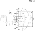
- FIG. 4A is a plan view showing the positional relationship in the horizontal direction in the working device 3, the working vehicle 2, and the RFID reader 11.
- the RFID reader 11 is provided at the rear portion of the cabin 9.
- the present invention is not limited to this, and the mounting position of the RFID reader 11 is arbitrary.
- the area spreading toward the working device 3, that is, the frame 50 or the working portion 40 around the RFID reader 11 is referred to as a "horizontal communication area J1".
- the center of the RFID reader 11 is the center position of the antenna that transmits radio waves.
- the area of radio waves transmitted from the antenna is set in advance, and is set to a predetermined angle with reference to the antenna.
- the opening angle (transmission angle) of the antenna is set to approximately 90 degrees with respect to the antenna.
- the horizontal communication area J1 is the area between one line L1 extending from the center of the antenna toward the working device 3 and the other line L2 extending from the center of the antenna toward the working device 3.
- the horizontal overlapping area K1 is an area of the portion of the device area S1 overlapping with the working vehicle 2 when an interval between a portion (for example, a transmission case 53) protruding from the most one side (left side) and a portion (for example, a side frame 54) protruding from the most other side (right side) in the working device 3 is defined as a "device area S1".
- the vehicle area T1 that is an area between of the portion of the device area S1 overlapping with the working vehicle 2 when an interval between a line L3 on one side extending from the portion (for example, the fender 31) protruding from the most one side (the left side) of the vehicle body 4 of the working vehicle 2 toward the working device 3 and the line L4 on the other side extending from the portion (for example, the fender 31) protruding from the most other side (the right side) of the vehicle body 4 of the working vehicle 2 toward the working device 3 is smaller than the device area S1, all of the device area T1 is included in the device area S1, and thus the horizontal overlapping area K1 is the same as the vehicle area T1.
- the RFID tag 10 is attached to the area (first attachment area) U1 including the horizontal overlapping area K1 in the horizontal communication area J1. That is, the RFID tag 10 is attached to the frame 50 or the working portion 40 included in the first attachment area U1.
- the RFID tag 10 is attached to a portion of the mast 56, the gear case 51, the support arm 52L, and the support arm 52R included in the attachment area U1, a part of the upper cover 57F included in the attachment area U1, and the like.
- the attachment position in the vertical direction of the RFID tag 10 is determined by the position in the vertical direction of the working device 3, the working vehicle 2, and the RFID reader 11, similarly to the horizontal direction.
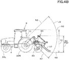
- FIG. 4B is a side view showing the positional relationship in the vertical direction in the working device 3, the working vehicle 2, and the RFID reader 11.
- the RFID reader 11 is provided at the rear of the cabin 9.
- the present invention is not limited to this, and the mounting position of the RFID reader 11 is arbitrary.
- the area spreading toward the working device 3, that is, the frame 50 or the working portion 40, centering on the RFID reader 11 is referred to as a "vertical communication area J2".
- the area of the vertical communication area J2 is set to be substantially 90 degrees centering on the antenna.
- the vertical communication area J2 is the area between one line N1 extending from the center of the antenna toward the working device 3 and the other line N2 extending from the center of the antenna toward the working device 3.
- the area in the vertical direction where the working vehicle 2 overlaps is defined as a "vertical overlapping area K2".
- the vertical overlapping area K2 is the area of the portion of the device area S2 which overlaps with the working vehicle 2.
- the vehicle area T2 that is an interval between a line N3 on one side extending from the portion (for example, the upper end of the cabin 9) protruding from the most one side (the upper side) of the vehicle body 4 of the working vehicle 2 toward the working device 3 and the line N4 on the other side extending from the portion (for example, the lower end of the rear wheel 30R) protruding from the most other side (the lower side) of the vehicle body 4 of the working vehicle 2 toward the working device 3 is larger than the device area S2, all of the device area S2 is included in the vehicle area T2, and thus the vertical overlapping area K2 is the same as the device area S2.
- the RFID tag 10 is mounted in the area (second attachment area) U2 that includes the vertical overlap area K2 in the vertical communication area J2. That is, the RFID tag 10 is attached to the frame 50 or the working portion 40 included in the second attachment area U2.
- the RFID tag 10 includes the mast 56, the gear case 51, the support arm 52L, the support arm 52R, the part of the upper cover 57F included in the attachment area U2, the part of the rear cover 57R included in the attachment area U2, for example.
- the RFID tag 10 is attached to the first attachment area U1 overlapping the horizontal communication area J1 spreading to the frame side around the RFID reader 11 that receives the identifying information of the RFID tag 10, that is, an area overlapped with the vehicle body 4 in the frame 50 in the horizontal direction.
- the RFID tag 10 is located in the first attachment area U1 which is the area overlapping with the working vehicle 2 within the communication area in the horizontal direction of the RFID reader 11, so that the RFID tag 10 transmits to the RFID reader 11, and it is possible to stably transmit the identifying information.
- the RFID tag 10 is attached to the second attachment area U2 overlapping the vertical communication area J2 spreading to the frame side around the RFID reader 11 that receives the identifying information of the RFID tag 10, that is, an area overlapped with the vehicle body 4 in the frame 50 in the vertical direction.
- the RFID tag 10 is located in the second attachment area U2, which is an area overlapping with the working vehicle 2 within the communication area in the vertical direction of the RFID reader 11, so that the RFID tag 10 can transmits the identifying information to the RFID reader 11 stably.
- the mounting position for mounting the RFID tag 10 on the working device 3 is set based not only on the relationship with the RFID reader 11 but also on the relationship between the working vehicle 2 and the working device 3.
- the identifying information from the working device 3 can be obtained even in the case where the working is performed with each of the working vehicle 2 and the working device 3 operated.
- the RFID tag 10 is mounted in an area that satisfies the first attachment area U1 and the second attachment area U2. In addition to this, the communication distance between the RFID tag 10 and the RFID reader 11 is taken into consideration.
- the RFID tag 10 is attached to the first attachment area U1 and the second attachment area U2.
- the RFID tag 10 is attached to a position that does not exceed the communication distance in the first attachment area U1 and the second attachment area U2.
- the mounting position in the horizontal direction of the RFID reader 11 will be described.
- the installation position in the horizontal direction of the RFID reader 11 is determined by the position in the horizontal direction of the working device 3, the working vehicle 2, and the RFID tag 10.
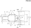
- FIG. 5A is a plan view showing the positional relationship in the horizontal direction in the working device 3, the working vehicle 2, and the RFID tag 10.
- the RFID tag 10 is provided in the gear case 51, the present invention is not limited to this, and the mounting position of the RFID tag 10 is arbitrary.
- the area spreading toward the working vehicle 2, that is, the vehicle body 4 around the RFID tag 10 as the center is set to a "horizontal communication area J3".
- the center of the RFID tag 10 is the center position of the antenna that transmits radio waves.
- the area of radio waves transmitted from the antenna is set in advance, and is set to a predetermined angle around the antenna.
- the opening angle (transmission angle) of the antenna is set to about 90 degrees with the antenna as the center.
- the horizontal communication area J3 is an area between one line L7 extending from the center of the antenna toward the working device 3 and the other line L8 extending from the center of the antenna toward the working device 3.
- a horizontal area where the working device 3 overlaps in the width direction is defined as a "horizontal overlapping area K3".
- the horizontal overlapping area K3 is a part that overlaps the device area S1 of the working device 3 in the vehicle area T1 of the working vehicle 2. Since the device area S1 is larger than the vehicle area T1, the horizontal overlap area K3 is the same as the vehicle area T1.
- the RFID reader 11 is attached to an area (third attachment area) U3 including the horizontal overlapping area K3 in the horizontal communication area J3. That is, the RFID reader 11 is attached to the third attachment area U3 including the horizontal overlapping area K3 in the vehicle body 4 or the connecting section 7. In the case of FIG. 5A , the RFID reader 11 can be attached to the cabin 9, the fender 31, and the like.
- the mounting position in the vertical direction of the RFID reader 11 is determined by the position in the vertical direction of the working device 3, the working vehicle 2, and the RFID tag 10, similarly to the horizontal direction.
- FIG. 5B is a side view showing the positional relationship in the vertical direction in the working device 3, the working vehicle 2, and the RFID tag 10. As shown in FIG. 5B , in a state where the working device 3 is connected to the working vehicle 2, an area spreading toward the working vehicle 2, that is, the vehicle body 4 around the RFID tag 10 as the center is defined as a "vertical communication area J4".
- the area of the vertical communication area J4 is set substantially at 90 degrees around the antenna like the horizontal direction.
- the vertical communication area J4 is an area between one line N5 extending from the center of the antenna toward the working vehicle 2 and the other line N6 extending from the center of the antenna toward the working vehicle 2.
- the vertical overlapping area K4 overlaps with the device area S2 of the working device 3 in the vehicle area T2 of the working vehicle 2. Since the device area S2 is smaller than the vehicle area T2, the horizontal overlapping area K4 is a part overlapping the device area S2.
- the RFID reader 11 is attached to an area (fourth attachment area) U4 that includes the vertical overlap area K4 in the vertical communication area J4. That is, the RFID reader 11 is attached to the fourth attachment area U4 including the horizontal overlapping area K3 in the vehicle body 4 or the connecting section 7. In the case of FIG. 5B , the RFID reader 11 can be attached to a portion of the fender 31 and the cabin 6 included in the attachment area U4.
- the RFID reader 11 is attached to the third attachment area that overlaps with the horizontal communication area spreading toward the vehicle body 4 side with respect to the RFID tag 10 as a center, that is, an area overlapping with the working device 3 in the vehicle body 4 in the horizontal direction.
- the RFID reader 11 is located in the third attachment area U3 which is the area overlapping with the working device 3 within the communication area in the horizontal direction of the RFID tag 10, so that the identifying information transmitted from the RFID tag 10 can be stably received by the RFID reader 11.
- the RFID reader 11 is mounted in a fourth attachment area U4 overlapping with a vertical communication area spreading toward the vehicle body 4 side with respect to the RFID tag 10 as a center in the area overlapping with the working device 3 in the vehicle body 4 in the vertical direction.
- the RFID reader 11 is located in the fourth attachment area U4, which is the area overlapping with the working device 3 within the communication area in the vertical direction of the RFID tag 10, so that the identifying information transmitted from the RFID tag 10 can be stably received by the RFID reader 11.
- the mounting position at which the RFID reader 11 is attached to the working vehicle 2 is set based not only on the relationship with the RFID tag 10 but also on the relationship between the working vehicle 2 and the working device 3, the working vehicle 2 and the working device 3, it is possible to acquire the identifying information from the working device 3 even in the case where the work is performed while each of them is operated.
- the RFID reader 11 is mounted in the area that satisfies the third attachment area U3 and the fourth attachment area U4, but in addition to this, the communication distance between the RFID tag 10 and the RFID reader 11 is taken into consideration.
- the RFID reader 11 is attached to the third attachment area U3 and the fourth attachment area U4.
- the RFID reader 11 is attached to a position not exceeding the communication distance in the third attachment area U3 and the fourth attachment area U4.
- the mounting position of the RFID tag 10 and the mounting position of the RFID reader 11 are separately explained.
- the RFID The tag 10 and the RFID reader 11 may be attached, respectively, or may be attached so as to satisfy only the condition of the RFID tag 10, or may be attached so as to satisfy only the condition of the RFID tag 10.
- the RFID tag 10 is attached to the working device 3, and the RFID reader 11 is attached to the working vehicle 2.
- the RFID reader 11 can acquire the identifying information of the RFID tag 10 only by bringing the working device 3 corresponding to the work close to the rear portion of the working vehicle 2.
- the types and shapes of the working vehicle 2 and the working device 3 are not limited. For example, as shown in FIG. 5C and FIG. 5D , it is also applicable to a boom sprayer having a large machine body width of the working device 3.
- the working device 3 includes the working portion 40 and the frame 50.
- the frame 50 is formed in a frame shape by a longitudinal member 50a, a cross member 50b, and the like.
- the working portion 40 has a tank 40a for storing chemicals and the like and a nozzle 40b attached to a support member projecting leftward or right from the rear portion of the frame 50.
- the RFID tag 10 is attached to the first attachment area U1 and the second attachment area U2.
- the RFID tag 10 can be attached to the longitudinal member 50a, the cross member 50b, and the tank 40a.
- the RFID reader 11 is attached to the third attachment area U3 and the fourth attachment area U4.
- the RFID reader 11 can be attached to the cabin 9 and the fender 31.
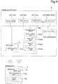
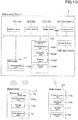
- FIG. 6 shows the management system of the working device.
- the management system of the working device in FIG. 6 is a system for managing the working device 3 using the RFID tag 10 and the RFID reader 11.
- the RFID tag 10 includes a communication part 10a and a storage part 10b.
- the storage part 10b is composed of a nonvolatile memory or the like, for example, and stores the identifying information of the working device 3.
- the communication part 10a is constituted of an antenna or the like, receives radio waves transmitted from the RFID reader 11, and transmits the identifying information stored in the storage part 10b to the RFID reader 11.
- the distance (output distance) of the identifying information outputted from the communication part 10a varies depending on the output of the radio wave transmitted from the RFID reader 11, but is roughly several tens cm to several tens of meters.
- the RFID reader 11 receives the identifying information output from the RFID tag 10.
- the RFID reader 11 has a communication part 11a.
- the communication part 11a outputs radio waves and receives the identifying information transmitted from the RFID tag 10.
- the communication part 11a outputs the data to an in-vehicle network such as CAN, NIN, FNexRay or the like provided in the vehicle body 4.
- This device 12 is a device constituting the working vehicle 2, and is, for example, a detection device 12a, a switch device 12b, a display device 12c, a control device 12d, and a communication device 12e.
- the detection device 12a is a device for detecting the operation state of the working vehicle 2 and includes an accelerator pedal sensor, a shift lever detection sensor, a crank position sensor, a fuel sensor, a water temperature sensor, an engine revolution sensor, a steering angle sensor, an oil temperature sensor, an axle rotation sensor, a cover sensor (a till depth sensor), a PTO revolution, and the like.
- the switch device 12b is a device that performs switching, and is an ignition switch, a parking brake switch, a PTO switch, or the like.
- the display device 12c is a device for displaying various items related to the working vehicle 2, and is a liquid crystal type display device 12c composed of liquid crystal or the like.
- the display device 12c is disposed in front of or in the side of the operator seat 8.
- the display device 12c displays, for example, the engine revolution speed, the gear shift stage, the water temperature, and the fuel. Further, the display device 12c displays the identifying information received by the RFID reader 11.
- the control device 12d is a device that controls the working vehicle 2 and is a CPU or the like.
- the communication device 12e is a device that communicates with the outside of the working vehicle 2 separately from the RFID reader 11.
- the plurality of devices 12 and the RFID reader 11 are connected via an in-vehicle network.
- a detection signal (detection value) detected by the detection device 12a a switch signal indicating switching of the switch device 12b, an operation unit (for example, the prime mover 5, electromagnetic valve, a pump, and the like), the identifying information received by the RFID reader 11, and the like are outputted.
- the control device 12d includes a first control device 12d1 and a second control device 12d2.
- the first control device 12d1 is a device that controls the entire working vehicle 2.
- the first control device 12dl is supplied with a detection value detected by the detection device 12a (for example, an operation amount of the accelerator pedal, a shift lever position (gear position) at the time of operation of the shift lever, a revolution speed of the prime mover, a gear position, an oil temperature, a crank position, cam position, and the like] are inputted.
- the first control device 12d1 outputs a control command to the second control device 12d2 so that the prime mover 5 reaches a predetermined rotation speed based on the operation amount of the accelerator pedal and controls the transmission device based on the shift lever position (shift control).
- the first control device 12d1 controls the ascending and descending of the three-point link mechanism based on the input from the operation member (up/down control).
- the second control device 12d2 is a device that mainly controls the prime mover 5.
- the second control device 12d2 controls the injector, the common rail, the supply pump, and the like based on the input of the operation amount of the accelerator pedal, the crank position, the cam position, and the like.
- the fuel injection amount, the injection timing, and the fuel injection rate are set in the control of the injector, and in the control of the supply pump and the common rail, the fuel injection pressure is set.
- the communication device 12e includes a communication part 12e1, a collecting part 12e2, an relating part 12e3, and a storage part 12e4.
- the communication part 12e1 is a device that performs short distance or long distance communication and can be connected to external devices.
- the communication part 12e1 is a communication module that performs wireless communication by the Wi-Fi (Wireless Fidelity (a registered trademark)) of the IEEE 802.11 series which is a communication standard.
- the communication part 12e1 may be a communication module that performs wireless communication via a cellular phone communication network or a communication module that performs wireless communication via a data communication network.
- the collecting part 12e2 sequentially collects operation information [detection signal (detection value), switch signal] of the device when the device is operated (when the prime mover 5 is driven).
- the collecting part 12e2 collects the operation amount of the accelerator pedal, the gear position, the rotation speed of the prime mover, the steering angle, the vehicle speed, the tilling depth, and the PTO rotation number as device operation information. Note that the operation information acquired by the collecting part 12e2 is not limited to the example described above.
- the relating part 12e3 associates the operation information collected by the collecting part 12e2 with the identifying information.
- the relating part 12e3 judges whether, for example, the prime mover 5 of the working vehicle 2 is driven or not (step S2).
- step S2 When the prime mover 5 is being driven (step S2, Yes), the relating part 12e3 determines whether collection of the operation information by the collecting part 12e2 has been started (step S2, Yes).
- the relating part 12e3 determines whether identifying information is output from the RFID reader 11 to the in-vehicle network (step S3).
- the relating part 12e3 associates the identifying information with the operation information collected by the collecting part 12e2 (step S4).
- the associated operation information and identifying information are stored in the storage part 12e4 composed of a nonvolatile memory or the like as a working record.
- the operation information and the identifying information associated by the relating part 12e3 are displayed on the display device 12c.
- the communication part 12e1 of the communication device 12e may transmit the operation information and the identifying information to the outside, and the mobile terminal 13 may display the operation information and the identifying information transmitted from the communication part 12e1.
- the mobile terminal 13 is composed of, for example, a smartphone (a multi-function mobile phone) and a tablet PC having a relatively high calculation capability.
- the mobile terminal 13 includes a communication part 13a that acquires information output from the communication part 12e1 of the communication device 12e, and the display part 13b.
- the communication part 13a is a communication module that performs wireless communication using IEEE 802.11 series of communication standards such as theWi-Fi (Wireless Fidelity (a registered trademark)).
- the communication part 13a may be a communication module that performs wireless communication via a cellular phone communication network or a communication module that performs wireless communication via a data communication network.
- the display part 13b is a liquid crystal panel or the like, and can display information received by the communication part 13a, for example, operation information and identifying information.
- the RFID tag 10 is attached to the working device 3, and the RFID reader 11 is attached to the working vehicle 2.
- the RFID reader 11 can acquire the identifying information of the RFID tag 10 only by bringing the working device 3 corresponding to the work close to the rear portion of the working vehicle 2.
- the RFID reader 11 can automatically acquire the identifying information by operating the working vehicle 2 and bringing the working vehicle 2 closer to the working device 3 to be worn by the worker.
- the RFID reader 11 By displaying the identifying information acquired by the RFID reader 11 on the display device 12c, the mobile terminal 13 or the like, it is possible to easily grasp which working device 3 is attached to the working vehicle 2. Further, even after the working device 3 is mounted on the working vehicle 2, the worker can confirm the working device 3 attached to the working vehicle 2.
- FIG. 8 shows a modified example of the management system of the working device.
- the management system of the working device includes a server 15 and a mobile terminal 13.
- the mobile terminal 13 includes a communication part 13a, a display part 13b, and a position detection part 13c.
- the communication part 13a is connectable to the communication device 12e and the server 15.
- the display part 13b is the same as the above-described embodiment.
- the position detection part 13c detects a position (for example, longitude, latitude) based on a signal of a positioning satellite such as GPS.
- the communication part 13a if the mobile terminal 13 is connected to the communication device 12e, it is possible for the communication part 13a to acquire the identifying information.
- the communication part 13a of the mobile terminal 13 transmits the acquired identifying information to the server 15 together with the position (hereinafter referred to as position information) detected by the position detection part 13c. Further, the communication part 13a may transmit the operation information to the server 15 in addition to the identifying information and the position information.
- the server 15 can acquire various information transmitted from the mobile terminal 13.
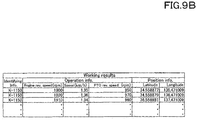
- the server 15 stores various pieces of information received from the mobile terminal 13 as work results. For example, as shown in FIG. 9A , when receiving the identifying information and the position information transmitted from the mobile terminal 13, the server 15 saves the identifying information and the position information as a work record.
- the identifying information is "Output from the RFID tag 10 of the working device 3" ⁇ "Received by the RFID reader 11 of the working vehicle 2 to which the working device 3 is attached” ⁇ "Output from the RFID reader 11" ⁇ “Received by the communication device 12e” ⁇ " Output from the communication device 12e " ⁇ "Received by the server via the mobile terminal 13".
- the predetermined working device 3 has been towed and worked by the predetermined working vehicle 2 with the fact that the identifying information is stored in the server, thereby improving the reliability of the work record.
- the server when the server receives the operation information, the identifying information, and the position information, the server stores the operation information, the identifying information, and the position information as a work record. In this case, it is possible to reliably ascertain which work has been performed in which field in the working device 3 indicated by the identifying information and the working vehicle 2 towing the working device 3.
- the operation information In addition to the identifying information, the operation information also reaches the server via the communication device 12e mounted on the predetermined working vehicle 2.
- the predetermined working vehicle 2 has towed and worked by the predetermined working vehicle 2 with the fact that the identifying information and the operation information corresponding to the identifying information are stored in the server.
- the position detection part 13c is provided in the mobile terminal 13.
- a configuration similar to that of the position detection part 13c may be provided in the communication device 12e.
- the communication device 12e also transmits the position information when transmitting the identifying information and the operation information to the mobile terminal 13. Further, the communication device 12e may transmit the identifying information, the operation information, and the position information to the server 15 through the cellular phone communication network or the data communication network.
- the RFID reader 11 receives the identifying information can grasp the position where the RFID reader fails to receive the identifying information, that is, the position where the working device 3 is separated from the working vehicle 2.
- FIG. 10 shows a management system of the working device according to the second embodiment.
- the management system of the working device will not be described in the same way as in the first embodiment.
- the mounting positions of the RFID tag 10 and the RFID reader 11 shown in the first embodiment are not limited.
- the management system of the working device includes an RFID tag 10 provided in the working device 3 and a code providing part 16.
- the RFID tag 10 has a communication part 10a and a storage part 10b.
- the code providing part 16 is separated from the RFID tag 10 in a graphic form, and is, for example, a bar code or two-dimensional code in which identifying information is shown by a figure such as a line.
- the code providing part 16 is a sheet on which a QR code (a registered trademark) is printed.
- the code providing part 16 may be any anything as long as it shows the identifying information of the RFID tag 10.
- the code providing part 16 is attached to the working device 3. Specifically, the code providing part 16 is installed in the working device 3 in the working portion 40 or the frame 50 near the RFID tag 10. Unlike the RFID tag 10, the code providing part 16 has no restriction on the mounting position and may be mounted anywhere.
- the identifying information of the RFID tag 10 and the code providing part 16 attached to the working device 3 are the same. That is, in the predetermined working device 3, the identifying information indicated by the code providing part 16 and the identifying information stored in the RFID tag 10 are the same.
- a code-attached RFID tag in which the RFID tag 10 and the code providing part 16 are integrated may be attached to the working device 3.
- the code-attached RFID tag 10 includes a housing 10c that stores the communication part 10a and the storage part 10b, and a sheet-like code providing part 16 that is attached to the housing 10c.
- the housing 10c has a mounting surface 10d to be attached to the working device 3 and a bonding surface 10e to which the code providing part 16 is attached.
- the code providing part 16 is attached to the attachment surface 10e of the housing 10c so that a figure indicating the code can be seen, and a transparent or translucent protective film 10f for protecting the figure is pasted on the code providing part 16.
- the protective film 10f on the lower right side of the casing 10c is peeled off from the sticking face 10e, but for the sake of convenience of explanation, it is intended to make it easy to understand the sticking face 10e and the protection film 10f. Actually, the protective film 10f on the lower right side of the casing 10c is also attached to the sticking surface 10e.
- the management system of the working device includes a reading part 17 and a registration part 18.
- the reading part 17 is a device for reading a figure of the code providing part 16, and is an imaging device such as a camera for imaging a figure.
- the registration part 18 decodes the figure read by the reading part 17 to the identifying information and registers the working device 3 in association with the decoded identifying information.
- the registration part 18 is mainly composed of a program stored in a computer (a server, a mobile terminal, a personal computer). As shown in FIG. 10 , the reading part 17 and the registration part 18 are provided in the mobile terminal 13 in the present embodiment.
- the reading part 17 is activated.
- the registration part 18 registers the pattern on the graphic of the code providing part 16 read by the reading part 17 as information indicating the identification information. In this manner, the identification information is decoded.
- the identification information decoded by the registration part 18 is displayed on the display part 13b of the mobile terminal 13.
- FIG. 12A shows a registration screen Q1 displaying the identifying information on the display part of the mobile terminal 13.
- a first input part 24 capable of inputting information (device information) on the working device 3 is displayed.
- first information can be input to the first input part 24, and a user (worker) or the like possessing the working device 3 can input, to the first input part 24, the device information such as the machine type, a model, a model number and the like of the working device 3, using an interface or the like.
- the registration part 18 registers the identifying information displayed on the registration screen Q1 and the identifying information and registers the device information input to the input part 24 in associated with each other.
- the registration part 18 associates the identifying information displayed on the registration screen Q1 with the machine type, the model, the model number, and the like of the working device 3, and stores them in the storage part 12e4 of the mobile terminal 13.
- the operator easily associate the identifying information of the RFID tag 10 the working device 3 and stores them in the mobile terminal 13.
- the identifying information of the RFID tag 10 and the code providing part 16 is the serial number of the working device 3 and the worker cannot grasp immediately the machine type, the model, the model number or the like, even if the operator sees the serial number.
- the machine type, the model, the model number and the like By inputting the machine type, the model, the model number and the like to the first input part 24, it is possible to associate the serial number with the machine type, the model, the model number or the like and to store them in the mobile terminal 13.
- the identifying information received by the RFID reader 11 is displayed on the mobile terminal 13 instead of the serial number, the machine type, the model, the model number or the like.
- the RFID tag 10 attached and the working device 3 to which the RFID tag 10 is attached can be certainly correlated, and it can be very easy to perform the initial setting on the RFID tag 10.
- FIG. 12B shows the registration screen Q2 displaying the identifying information on the display part 13b of the mobile terminal 13.
- the registration screen Q2 not only the first input part 24 but also a second input part 25 capable of inputting information (second information) on the user (worker) are displayed.
- second information information
- Various pieces of user information can be input to the second input part 25, and the user or the like inputs, for example, the name of the user to the second input part 25 using an interface or the like.
- the user's address, contact address, sex, age, and the like may be inputted to the second input part 25 as the user information.
- the user is a company
- the name of the company that owns the working device 3, the department to which the working machine 3 belongs, and the like may be inputted as the user information.
- the registration part 18 After the device information is input to the first input part 24 of the display part 13b of the mobile terminal 13 and the user information is input to the second input part 25, when the completion button 26 shown on the registration screen is selected, the registration part 18 relates the identifying information displayed on the registration screen Q2, the device information inputted to the first input part 24, and the user information inputted to the second input part 25 to each other and registers them.
- the registration part 18 associates the identifying information displayed on the registration screen Q2 with the machine type, the model number, the name, and the like of the working device 3, and stores them in the storage part 12e4 of the mobile terminal 13.
- the worker can easily associate the identifying information of the RFID tag 10 with the working device 3 and the user.
- the operator when an operator enters the user information to the registration screen Q2 at the time of attaching the RFID tag 10, the operator can definitely associate the installed RFID tag 10 and the user using the working device 3 on the spot, and it can be very easy to perform the initial setting on the RFID tag 10.
- the reading part (an imaging device) 17 and the mobile terminal 13 may be configured separately, and the image read by the reading part 17 or the identifying information after restoration may be transmitted from the reading part 17 to the mobile terminal 13.
- the registration part 18 registers the decoded identifying information in association with the working device 3.
- the identifying information can be read by the code providing part 16 and used as a backup of the identifying information even when the RFID tag 10 cannot transmit the identifying information for some reason.
- FIG. 13 shows a management system of the working device according to the third embodiment.
- the third embodiment is a modification of the management system of the working device shown in the second embodiment. Descriptions of parts similar to those of the first embodiment and the second embodiment will be omitted.
- the management system of the working device includes an RFID tag 10 provided in the working device 3 and a code providing part 16.
- the RFID tag 10 has a communication part 10a and a storage part 10b.
- the code providing part 16 is similar to the code providing part 16 shown in the second embodiment. Incidentally, also in the third embodiment, the code-attached RFID tag may be attached to the working device 3.
- the mobile terminal 13 includes a communication part 13a, a display part 13b, a reading part 17, and a decoding part 20.
- the decoding part 20 is constituted of a program or the like stored in the mobile terminal 13. When the program (application software) for registering the RFID tag 10 and the like is activated in the mobile terminal 13, the reading part 17 is activated.
- the decoding part 20 converts the pattern on the graphic of the code providing part 16 read by the reading part 17 into information indicating the identifying information, whereby identifying the information thereof.
- a registration screen Q1 or a registration screen Q2 is displayed on the display part 13b of the mobile terminal 13.
- the identifying information decoded by the decoding part 20 is displayed.
- the communication part 13a transmits the identifying information and the device information to the server 15, the device information being entered to the first input part 24 of the registration screen Q1 and the device information being displayed on the registration screen Q1.
- the communication part 13a transmits the identifying information, the device information, and the user information to the server 15, the device information being entered to the first input part 24 of the registration screen Q2, the device information being inputted to the registration screen Q2, and the user information being entered to the second input part 25 of the registration screen Q2.
- the server 15 has a registration part 18 and an obtaining part 21.
- the registration part 18 and the obtaining part 21 are composed of programs and the like stored in the server 15.
- the server 15 receives the identifying information and the device information transmitted from the mobile terminal 13, the obtaining part 21 acquires the received identifying information and device information.
- the registration part 18 associates the identifying information acquired by the obtaining part 21 with the device information and stores them in the storage part 12e4.
- the device information is input to the registration screen Q1 displayed on the display part 13b of the mobile terminal 13 and transmitted to the server 15.
- the worker can easily associate the identifying information of the RFID tag 10 with the working device 3 and register them in the server 15.
- the obtaining part 21 of the server 15 acquires the device information, the user information, and the identifying information.
- the registration part 18 associates the identifying information acquired by the obtaining part 21 with the device information and the user information, and stores them in the storage part 22.
- the device information and the user information are inputted to the registration screen Q2 displayed on the display part 13b of the mobile terminal 13, and the server 15.
- the worker can easily associate the identifying information of the RFID tag 10 with the working device 3 and the user, and register them to the server 15.
- the work record and the user when storing the work record, the work record and the user can be associated with each other using the identifying information in the server 15, and the work performed by the user can be grasped.
- the machine type, the model, the model number, and the like are not included in the identifying information of the RFID tag 10, it is possible to correlate the machine type, the model, the model number, and the like of the working device 3 with the work record. Thus, it is possible to grasp which working device 3 provides the work record.
Landscapes
- Engineering & Computer Science (AREA)
- Life Sciences & Earth Sciences (AREA)
- Physics & Mathematics (AREA)
- General Physics & Mathematics (AREA)
- Theoretical Computer Science (AREA)
- Business, Economics & Management (AREA)
- Mechanical Engineering (AREA)
- Soil Sciences (AREA)
- Environmental Sciences (AREA)
- Computer Hardware Design (AREA)
- Microelectronics & Electronic Packaging (AREA)
- Finance (AREA)
- Accounting & Taxation (AREA)
- Development Economics (AREA)
- Strategic Management (AREA)
- Computer Networks & Wireless Communication (AREA)
- Economics (AREA)
- Marketing (AREA)
- General Business, Economics & Management (AREA)
- Entrepreneurship & Innovation (AREA)
- Game Theory and Decision Science (AREA)
- Zoology (AREA)
- Agricultural Machines (AREA)
- Health & Medical Sciences (AREA)
- Toxicology (AREA)
- Electromagnetism (AREA)
- General Health & Medical Sciences (AREA)
- Artificial Intelligence (AREA)
- Computer Vision & Pattern Recognition (AREA)
- Traffic Control Systems (AREA)
- Computer Security & Cryptography (AREA)
- General Engineering & Computer Science (AREA)
- Signal Processing (AREA)
Abstract
Description
- The present invention relates to a working device, a working vehicle, and a working machine having the working device and the working vehicle.
- Conventionally, the technique disclosed in
Patent Document 1 is known as a work device (an implement) such as a tilling device connected to the rear portion of a tractor. The tractor disclosed inPatent Document 1 includes a link mechanism (a three-point link mechanism) provided at a rear portion of a vehicle body and a tilling device detachable via a link mechanism. - [Patent Document 1] Japanese Unexamined Patent Application Publication No.
2004-024052 - There are various working devices besides tilling devices as working devices to be attached to and detached from the link mechanism of the tractor. The working device is attached to and detached from the link mechanism of the tractor in accordance with the work. The tractor (a vehicle body) and the working device are seldom electrically connected to each other, and in such a case, it is actually difficult to obtain information on the working device on the side of the tractor (the vehicle body).
- When connecting the tractor and the working device via a cable or the like, the connector on the tractor side and the connector on the working device side must correspond to each other, and the connector of the working device corresponds to the connector on the tractor side. If not, it is impossible to connect, and even in this case it is actually difficult to obtain information on the work device on the tractor side.
- Even if the working device and the tractor can be connected by cables or the like, information on the working device may not be obtained in some circumstances. When information on the working device cannot be obtained, it is impossible to grasp which work device is attached.
- In view of the above problems, it is an object of the present invention to provide a working device, a work vehicle, and a working machine that can easily transmit and receive identifying information of the working device by a wireless tag. It is another object of the present invention to provide a management system for a work device which can easily grasp at least what kind of work device is.
- A working device includes: a working portion configured to perform work; a frame supporting the working portion and being configured to be coupled to a vehicle body; and a wireless tag attached to the working portion or to the frame, having: a storage part configured to store at least identifying information; and a communication part configured to transmit the identifying information.
- The wireless tag is attached to a first attachment area overlapped with a horizontal communication area expanded on the frame side around a wireless tag reader, that is, an area of the frame overlapped with the vehicle body in a horizontal direction, the wireless tag reader being configured to receive the identifying information of the wireless tag.
- The wireless tag is attached to a second attachment area overlapped with a vertical communication area expanded on the frame side around the wireless tag reader, that is, an area of the frame overlapped with the vehicle body in a vertical direction, the wireless tag reader being configured to receive the identifying information of the wireless tag.
- The working device mentioned above includes a code providing part configured to provide, as a code, the identifying information of the wireless tag.
- A working vehicle includes: a vehicle body; a coupling portion disposed on the vehicle body and configured to be coupled to a working device; and a wireless tag reader configured to receive identifying information of the working device and attached to the vehicle body or to the coupling portion.
- The wireless tag is attached to a third attachment area overlapped with a horizontal communication area expanded on the vehicle body side around a communication part, that is, an area of the vehicle body overlapped with the working device in a horizontal direction, the communication part being configured to transmit the identifying information of the wireless tag.
- The wireless tag is attached to a fourth attachment area overlapped with a vertical communication area expanded on the vehicle body side around a communication part, that is, an area of the vehicle body overlapped with the working device in a vertical direction, the communication part being configured to transmit the identifying information of the wireless tag.
- A working machine, includes a working vehicle having: a vehicle body; a coupling portion disposed on the vehicle body; and a wireless tag reader attached to the vehicle body or the coupling portion and configured to receive identifying information; and a working device having: a working portion configured to perform work; a frame supporting the working portion and being coupled to the coupling portion; and a wireless tag attached to the working portion or to the frame and configured to transmit the identifying information.
- A management system for a working device includes: a wireless tag attached to the working device, having a communicating part to transmit at least identifying information; a code providing part providing the identifying information of the wireless tag with use of a graphic; a reading part configured to read the graphic of the code providing part; a registration part configured to decode, into the identifying information, the graphic read by the reading part, to relate the decoded identifying information to the working device, and to register the decoded identifying information and the working device.
- The management system for the working device mentioned above, includes: a displaying part configured to display the decoded identifying information; and a first inputting part to which first information relating to the working device is inputted. The registration part relates the identifying information displayed on the displaying part to the first information inputted to the first inputting part, and registers the identifying information and the first information.
- The management system for the working device mentioned above, includes a second inputting part to which information of a user owning the working device. The registration part relates the identifying information displayed on the displaying part to the first information inputted to the first inputting part and second information inputted to the second inputting part, and registers the identifying information, the first information, and the second information.
- A management system for a working device, includes: a wireless tag attached to the working device, having a communicating part to transmit at least identifying information; a code providing part providing the identifying information of the wireless tag with use of a graphic; a mobile terminal having: a reading part configured to read the graphic of the code providing part; a registration part configured to decode, into the identifying information, the graphic read by the reading part, to relate the decoded identifying information to the working device, and to register the decoded identifying information and the working device.
- The mobile terminal has: a displaying part configured to display the decoded identifying information; and a first inputting part to which first information relating to the working device is inputted. The registration part relates the identifying information displayed on the displaying part to the first information inputted to the first inputting part, and registers the identifying information and the first information.
- The mobile terminal has a second inputting part to which information of a user owning the working device is inputted. The registration part relates the identifying information displayed on the displaying part to the first information inputted to the first inputting part and second information inputted to the second inputting part, and registers the identifying information, the first information, and the second information.
- A management system for a working device, includes: a wireless tag attached to the working device, having a communicating part to transmit at least identifying information; a code providing part providing the identifying information of the wireless tag with use of a graphic; a mobile terminal having: a reading part configured to read the graphic of the code providing part; a decoding part configured to decode, into the identifying information, the graphic read by the reading part; and a communication part configured to transmit the decoded identifying information; and a server having: an obtaining part configured to obtain the identifying information transmitted from the mobile terminal; and a registration part configured to relate the identifying information received by the obtaining part to the working device, and to register the identifying information and the working device.
- The mobile terminal has: a displaying part configured to display the decoded identifying information; and a first inputting part to which first information relating to the working device is inputted. The communication part transmits, to the server, the decoded identifying information and the first information. And, the registration part relates the identifying information transmitted from the communication part to the first information, and registers the identifying information and the first information.
- The mobile terminal has a second inputting part to which information of a user owning the working device is inputted. The communication part transmits, to the server, the second information inputted to the second inputting part. And, the registration part relates the identifying information transmitted from the communication part to the first information and the second information, and registers the identifying information, the first information, and the second information.
- According to the present invention, the identifying information of the working device can be easily transmitted and received by the wireless tag.
-
-
FIG. 1 is a view illustrating a whole view of a working machine in which a working device is coupled to a working vehicle according to a first embodiment of the present embodiment. -
FIG. 2 is a first explanation view illustrating the working device according to the first embodiment. -
FIG. 3 is a second explanation view illustrating the working device according to the first embodiment. -
FIG. 4A is a plan view illustrating a positional relation between the working device, a working vehicle, and an RFID reader in a horizontal direction according to the first embodiment. -
FIG. 4B is a side view illustrating a positional relation between the working device, the working vehicle, and the RFID reader in a vertical direction according to the first embodiment. -
FIG. 5A is a plan view illustrating a positional relation between the working device, the working vehicle, and the RFID reader in the horizontal direction according to the first embodiment. -
FIG. 5B is a side view illustrating a positional relation between the working device, the working vehicle, and the RFID reader in the vertical direction according to the first embodiment. -
FIG. 5C is a plan view illustrating a positional relation between the working device, the working vehicle, and the RFID reader in the horizontal direction according to the first embodiment. -
FIG. 5D is a side view illustrating a positional relation between the working device, the working vehicle, and the RFID reader in the vertical direction according to the first embodiment. -
FIG. 6 is a view illustrating a management system of the working device according to the first embodiment. -
FIG. 7 is a view illustrating an operational flow of a relating part according to the first embodiment. -
FIG. 8 is a view illustrating a modified example of a management system of the working device according to the first embodiment. -
FIG. 9A is a view illustrating a case where identifying information and positional information are stored as working results according to the first embodiment. -
FIG. 9B is a view illustrating a case where operational information, the identifying information and the positional information are stored as the working results according to the first embodiment. -
FIG. 10 is a view illustrating a management system for a working device according to a second embodiment of the present invention. -
FIG. 11A is a view illustrating an example in which a code providing part and an RFID tag are attached to the working device according to the second embodiment. -
FIG. 11B is a view illustrating an RFID with code constituted by integrating the RFID tag and the code providing part according to the second embodiment. -
FIG. 12A is a view illustrating a first registration screen according to the second embodiment. -
FIG. 12B is a view illustrating a second registration screen according to the second embodiment. -
FIG. 13 is a view illustrating a management system for a working device according to a third embodiment of the present invention. - Hereinafter, embodiments of the present invention will be described with reference to the drawings.
- The working machine will be described.
-
FIG. 1 shows an overall view of the workingmachine 1. Thework machine 1 includes a workingvehicle 2 and a workingdevice 3. For convenience of explanation, it is assumed that the front side (the left side inFIG. 1 ) of the operator seated in theoperator seat 8 provided in the workingvehicle 2 is the front, the rear side (the right side inFIG. 1 ) of the operator is the rear, the left side (the front surface side inFIG. 1 ) of the operator is the left, and the right side (the back surface side inFIG. 1 ) of the operator is the right. - The working
vehicle 2 is a tractor capable of pulling the workingdevice 3. The workingvehicle 2 includes avehicle body 4 and a travelingdevice 30 mounted on thevehicle body 4. Thevehicle body 4 is constituted of directly connecting aprime mover 5, a clutch housing having a clutch, a transmission case having a transmission device, a differential case having a differential device, and the like. - The
prime mover 5 may be an engine, a motor, or both a motor and an engine. The travelingdevice 30 is a wheeltype running device 30 having afront wheel 30F rotatably supported on the axle of the front portion of thevehicle body 4 and arear wheel 30R rotatably supported on the axle of the rear portion of thevehicle body 4. - The upper portion of the
rear wheel 30R is covered with afender 31 provided at the rear portion of thevehicle body 4. Note that the travelingdevice 30 may be a crawler type traveling device. - The
vehicle body 4 is provided with anoperator seat 8. A steering wheel or the like for operating the travelingdevice 30 is provided in front of theoperator seat 8. Thevehicle body 4 may be provided with acabin 9 surrounding theoperator seat 8. APTO shaft 32 that is rotated by the power of theprime mover 5 and the like projects from the rear portion of thevehicle body 4 and is capable of transmitting the rotational driving force of thePTO shaft 32 to the workingdevice 3. - The
vehicle body 4 is provided with a connecting portion 7 for connecting the workingdevice 3. The connecting portion 7 is, for example, a three-point link mechanism provided at the rear portion of thevehicle body 4. The connecting portion 7 includes a pair oflower links 35 provided at the rear portion of thevehicle body 4, atop link 36 provided at the upper portion of thelower link 35 at the rear portion of thevehicle body 4, alower link 35 and atop link 36 and has a connectingframe 37. - The front end of the
lower link 35 is rotatably provided at the rear portion of thevehicle body 4. The rear end of thelower link 35 is rotatably provided on the connectingframe 37. The front end of thetop link 36 is provided at the rear portion of thevehicle body 4 so as to be rotatable on the upper portion of thelower link 35. The rear end of thetop link 36 is rotatably provided on the connectingframe 37. Further, theframe 50 of the workingdevice 3 is detachably connected to the connectingframe 37. - In this embodiment, the connecting portion 7 is constituted of a three-point link mechanism, but it may be constituted of a two-point link mechanism or another mechanism, and is not limited thereto. In the embodiment described above, the
frame 50 of the workingdevice 3 is connected to the connectingframe 37. However, the other ends of thelower link 35 and thetop link 36 may be connected to theframe 50 of the workingdevice 3. - The working
device 3 includes a workingportion 40 for performing working and aframe 50 for supporting the workingportion 40. Theframe 50 is connected to thevehicle body 4 via the connecting portion 7. The workingdevice 3 is, for example, a tilling device which cultivates. - For the sake of convenience of explanation, the working
device 3 will be described by taking a tilling device as an example. As a matter of course, the workingdevice 3 is connected to the workingvehicle 2 such as a device other than a tilling device, a fertilizer spraying device for spraying fertilizer, an agricultural chemical spraying device for spraying agricultural chemicals, a harvesting device for harvesting, a ridging device, and the like. Any device may be used as long as it operates. - As shown in
FIG. 2 andFIG. 3 , theframe 50 includes agear case 51, aleft support arm 52L, aright support arm 52R, atransmission case 53, and aside frame 54. Thegear case 51 is located substantially at the center in the width direction of the workingdevice 3. - The
support arm 52L protrudes leftward from the left part of thegear case 51. Thesupport arm 52R protrudes rightward from the right part of thegear case 51. The upper portion of thetransmission case 53 is attached to the left end portion of thesupport arm 52L. The upper portion of theside frame 54 is attached to the right end portion of thesupport arm 52R. - Further, the
frame 50 has a left support stay 55L, a right support stay 55R, and amast 56. The support stay 55L is fixed to thesupport arm 52L. The support stay 55R is fixed to thesupport arm 52R. Themast 56 is fixed to thegear case 51. The front portion of themast 56 is connected to the connectingframe 37. - Further, the
frame 50 has acover 57 covering the workingportion 40. Thecover 57 includes an upper cover 57L covering the upper side of the workingportion 40 and arear cover 57R covering the rear side of the workingportion 40. - The working
portion 40 has arotating shaft 58 rotatably supported between thetransmission case 53 and theside frame 54, and a tillingclaw 59 provided on therotating shaft 58. The rotatingshaft 58 rotates by the power of thePTO shaft 32 on the work vehicle side. - More specifically, the
gear case 51 is provided with an intake shaft, and the power of thePTO shaft 32 is transmitted to the intake shaft via the joint. The power transmitted to the intake shaft is transmitted to the chain transmission means in thetransmission case 53 via the gear mechanism in thegear case 51 and the shaft in the support arm. - The
rotary shaft 58 is driven by the power transmitted to the chain transmission means. The rotatingshaft 58 is rotated in the direction indicated by the arrowed line A1 inFIG. 1 . When therotating shaft 58 rotates in the A1 direction, the tillingclaw 59 plows the soil and releases it to the rear portion. - As shown in
FIG. 6 , the workingdevice 3 is provided with a wireless tag, that is, an RFID tag (Radio Frequency Identification) 10. TheRFID tag 10 is a passive type RFID tag and is a tag that transmits identifying information of at least the workingdevice 3. - The identifying information is information for specifying, that is, identifying the working
device 3. The identifying information may be any information as long as it is information for identifying the workingdevice 3, it may be a unique number (serial number) individually assigned to each of the workingdevices 3, a type of the workingdevice 3, a model number, or information including a type. - Further, the working
vehicle 2 is provided with a wireless tag reader that receives the identifying information of theRFID tag 10, that is, theRFID reader 11. The direction (transmission direction) of the radio wave (signal) transmitted from theRFID reader 11 is directed to the workingdevice 3, theRFID tag 10 receives the radio wave transmitted from theRFID reader 11 and transmits the identifying information to theRFID reader 11 to be transmitted. - The mounting position in the horizontal direction of the
RFID tag 10 will be described. - The installation position in the horizontal direction of the
RFID tag 10 is determined by the position in the horizontal direction of the workingdevice 3, the workingvehicle 2, and theRFID reader 11.FIG. 4A is a plan view showing the positional relationship in the horizontal direction in the workingdevice 3, the workingvehicle 2, and theRFID reader 11. - In
FIG. 4A , theRFID reader 11 is provided at the rear portion of thecabin 9. However, the present invention is not limited to this, and the mounting position of theRFID reader 11 is arbitrary. - As shown in
FIG. 4A , in a state where the workingdevice 3 is connected to the workingvehicle 2, the area spreading toward the workingdevice 3, that is, theframe 50 or the workingportion 40 around theRFID reader 11 is referred to as a "horizontal communication area J1". The center of theRFID reader 11 is the center position of the antenna that transmits radio waves. - In other words, in the
RFID reader 11, the area of radio waves transmitted from the antenna is set in advance, and is set to a predetermined angle with reference to the antenna. In this embodiment, the opening angle (transmission angle) of the antenna is set to approximately 90 degrees with respect to the antenna. - Thus, the horizontal communication area J1 is the area between one line L1 extending from the center of the antenna toward the working
device 3 and the other line L2 extending from the center of the antenna toward the workingdevice 3. - Further, in a state in which the working
device 3 is attached to the workingvehicle 2, when attention is paid to the workingdevice 3, the area in the horizontal direction where the workingvehicle 2 overlaps in the width direction is set as a "horizontal overlapping area K1". First, as shown inFIG. 4A , the horizontal overlapping area K1 is an area of the portion of the device area S1 overlapping with the workingvehicle 2 when an interval between a portion (for example, a transmission case 53) protruding from the most one side (left side) and a portion (for example, a side frame 54) protruding from the most other side (right side) in the workingdevice 3 is defined as a "device area S1". - Specifically, in
FIG. 4A , the vehicle area T1 that is an area between of the portion of the device area S1 overlapping with the workingvehicle 2 when an interval between a line L3 on one side extending from the portion (for example, the fender 31) protruding from the most one side (the left side) of thevehicle body 4 of the workingvehicle 2 toward the workingdevice 3 and the line L4 on the other side extending from the portion (for example, the fender 31) protruding from the most other side (the right side) of thevehicle body 4 of the workingvehicle 2 toward the workingdevice 3 is smaller than the device area S1, all of the device area T1 is included in the device area S1, and thus the horizontal overlapping area K1 is the same as the vehicle area T1. - The
RFID tag 10 is attached to the area (first attachment area) U1 including the horizontal overlapping area K1 in the horizontal communication area J1. That is, theRFID tag 10 is attached to theframe 50 or the workingportion 40 included in the first attachment area U1. - In the case of
FIG. 4A , for example, theRFID tag 10 is attached to a portion of themast 56, thegear case 51, thesupport arm 52L, and thesupport arm 52R included in the attachment area U1, a part of theupper cover 57F included in the attachment area U1, and the like. - Next, the mounting position in the vertical direction of the
RFID tag 10 will be described. - The attachment position in the vertical direction of the
RFID tag 10 is determined by the position in the vertical direction of the workingdevice 3, the workingvehicle 2, and theRFID reader 11, similarly to the horizontal direction. -
FIG. 4B is a side view showing the positional relationship in the vertical direction in the workingdevice 3, the workingvehicle 2, and theRFID reader 11. InFIG. 4B , theRFID reader 11 is provided at the rear of thecabin 9. However, the present invention is not limited to this, and the mounting position of theRFID reader 11 is arbitrary. - As shown in
FIG. 4B , in a state where the workingdevice 3 is connected to the workingvehicle 2, the area spreading toward the workingdevice 3, that is, theframe 50 or the workingportion 40, centering on theRFID reader 11 is referred to as a "vertical communication area J2". Similarly to the horizontal direction, the area of the vertical communication area J2 is set to be substantially 90 degrees centering on the antenna. - Thus, the vertical communication area J2 is the area between one line N1 extending from the center of the antenna toward the working
device 3 and the other line N2 extending from the center of the antenna toward the workingdevice 3. - Further, in a state in which the working
device 3 is attached to the workingvehicle 2, when paying attention to the workingdevice 3, the area in the vertical direction where the workingvehicle 2 overlaps is defined as a "vertical overlapping area K2". First, as shown inFIG. 4B , between the portion (for example, the mast 56) protruding from the most one (upper side) and the portion protruding from the other (lower side) (for example, the tilling claw 59) in the workingdevice 3 is set as the a "device area S2", the vertical overlapping area K2 is the area of the portion of the device area S2 which overlaps with the workingvehicle 2. - In
FIG. 4B , the vehicle area T2 that is an interval between a line N3 on one side extending from the portion (for example, the upper end of the cabin 9) protruding from the most one side (the upper side) of thevehicle body 4 of the workingvehicle 2 toward the workingdevice 3 and the line N4 on the other side extending from the portion (for example, the lower end of therear wheel 30R) protruding from the most other side (the lower side) of thevehicle body 4 of the workingvehicle 2 toward the workingdevice 3 is larger than the device area S2, all of the device area S2 is included in the vehicle area T2, and thus the vertical overlapping area K2 is the same as the device area S2. - The
RFID tag 10 is mounted in the area (second attachment area) U2 that includes the vertical overlap area K2 in the vertical communication area J2. That is, theRFID tag 10 is attached to theframe 50 or the workingportion 40 included in the second attachment area U2. - In the case of
FIG. 4B , theRFID tag 10 includes themast 56, thegear case 51, thesupport arm 52L, thesupport arm 52R, the part of theupper cover 57F included in the attachment area U2, the part of therear cover 57R included in the attachment area U2, for example. - As described above, according to the working
device 3, theRFID tag 10 is attached to the first attachment area U1 overlapping the horizontal communication area J1 spreading to the frame side around theRFID reader 11 that receives the identifying information of theRFID tag 10, that is, an area overlapped with thevehicle body 4 in theframe 50 in the horizontal direction.. - Thus, the
RFID tag 10 is located in the first attachment area U1 which is the area overlapping with the workingvehicle 2 within the communication area in the horizontal direction of theRFID reader 11, so that theRFID tag 10 transmits to theRFID reader 11, and it is possible to stably transmit the identifying information. - According to the working
device 3, theRFID tag 10 is attached to the second attachment area U2 overlapping the vertical communication area J2 spreading to the frame side around theRFID reader 11 that receives the identifying information of theRFID tag 10, that is, an area overlapped with thevehicle body 4 in theframe 50 in the vertical direction. - Thus, the
RFID tag 10 is located in the second attachment area U2, which is an area overlapping with the workingvehicle 2 within the communication area in the vertical direction of theRFID reader 11, so that theRFID tag 10 can transmits the identifying information to theRFID reader 11 stably. - That is, since the mounting position for mounting the
RFID tag 10 on the workingdevice 3 is set based not only on the relationship with theRFID reader 11 but also on the relationship between the workingvehicle 2 and the workingdevice 3. Thus, the identifying information from the workingdevice 3 can be obtained even in the case where the working is performed with each of the workingvehicle 2 and the workingdevice 3 operated. - In the working
device 3, theRFID tag 10 is mounted in an area that satisfies the first attachment area U1 and the second attachment area U2. In addition to this, the communication distance between theRFID tag 10 and theRFID reader 11 is taken into consideration. - For example, when the front-rear width or the body width of the working
device 3 is small and the communication distance is sufficiently large with respect to the first attachment area U1 and the second attachment area U2 (The longest distance of the first attachment area U1 and the second attachment area U2 < Communication distance), theRFID tag 10 is attached to the first attachment area U1 and the second attachment area U2. - On the other hand, when the front-rear width or the body width of the working
device 3 is large and the communication distance is small with respect to the first attachment area U1 and the second attachment area U2 (The longest distance of the first attachment area U1 and the second attachment area U2 > Communication distance), theRFID tag 10 is attached to a position that does not exceed the communication distance in the first attachment area U1 and the second attachment area U2. - The mounting position in the horizontal direction of the
RFID reader 11 will be described. - The installation position in the horizontal direction of the
RFID reader 11 is determined by the position in the horizontal direction of the workingdevice 3, the workingvehicle 2, and theRFID tag 10. -
FIG. 5A is a plan view showing the positional relationship in the horizontal direction in the workingdevice 3, the workingvehicle 2, and theRFID tag 10. InFIG. 5A , although theRFID tag 10 is provided in thegear case 51, the present invention is not limited to this, and the mounting position of theRFID tag 10 is arbitrary. - As shown in
FIG. 5A , in a state where the workingdevice 3 is connected to the workingvehicle 2, the area spreading toward the workingvehicle 2, that is, thevehicle body 4 around theRFID tag 10 as the center is set to a "horizontal communication area J3". The center of theRFID tag 10 is the center position of the antenna that transmits radio waves. - In other words, in the
RFID tag 10, the area of radio waves transmitted from the antenna is set in advance, and is set to a predetermined angle around the antenna. In this embodiment, the opening angle (transmission angle) of the antenna is set to about 90 degrees with the antenna as the center. - Thus, the horizontal communication area J3 is an area between one line L7 extending from the center of the antenna toward the working
device 3 and the other line L8 extending from the center of the antenna toward the workingdevice 3. - Further, in a state in which the working
device 3 is attached to the workingvehicle 2, when focusing on the workingvehicle 2, a horizontal area where the workingdevice 3 overlaps in the width direction is defined as a "horizontal overlapping area K3". The horizontal overlapping area K3 is a part that overlaps the device area S1 of the workingdevice 3 in the vehicle area T1 of the workingvehicle 2. Since the device area S1 is larger than the vehicle area T1, the horizontal overlap area K3 is the same as the vehicle area T1. - The
RFID reader 11 is attached to an area (third attachment area) U3 including the horizontal overlapping area K3 in the horizontal communication area J3. That is, theRFID reader 11 is attached to the third attachment area U3 including the horizontal overlapping area K3 in thevehicle body 4 or the connecting section 7. In the case ofFIG. 5A , theRFID reader 11 can be attached to thecabin 9, thefender 31, and the like. - Next, the mounting position in the vertical direction of the
RFID reader 11 will be described. - The mounting position in the vertical direction of the
RFID reader 11 is determined by the position in the vertical direction of the workingdevice 3, the workingvehicle 2, and theRFID tag 10, similarly to the horizontal direction. -
FIG. 5B is a side view showing the positional relationship in the vertical direction in the workingdevice 3, the workingvehicle 2, and theRFID tag 10. As shown inFIG. 5B , in a state where the workingdevice 3 is connected to the workingvehicle 2, an area spreading toward the workingvehicle 2, that is, thevehicle body 4 around theRFID tag 10 as the center is defined as a "vertical communication area J4". - The area of the vertical communication area J4 is set substantially at 90 degrees around the antenna like the horizontal direction. Thus, the vertical communication area J4 is an area between one line N5 extending from the center of the antenna toward the working
vehicle 2 and the other line N6 extending from the center of the antenna toward the workingvehicle 2. - Further, in a state where the working
device 3 is attached to the workingvehicle 2, when focusing on the workingvehicle 2, the area in the vertical direction where the workingdevice 3 overlaps is defined as a "vertical overlapping area K4". - First, as shown in
FIG. 5B , the vertical overlapping area K4 overlaps with the device area S2 of the workingdevice 3 in the vehicle area T2 of the workingvehicle 2. Since the device area S2 is smaller than the vehicle area T2, the horizontal overlapping area K4 is a part overlapping the device area S2. - The
RFID reader 11 is attached to an area (fourth attachment area) U4 that includes the vertical overlap area K4 in the vertical communication area J4. That is, theRFID reader 11 is attached to the fourth attachment area U4 including the horizontal overlapping area K3 in thevehicle body 4 or the connecting section 7. In the case ofFIG. 5B , theRFID reader 11 can be attached to a portion of thefender 31 and the cabin 6 included in the attachment area U4. - As described above, according to the working
vehicle 2, theRFID reader 11 is attached to the third attachment area that overlaps with the horizontal communication area spreading toward thevehicle body 4 side with respect to theRFID tag 10 as a center, that is, an area overlapping with the workingdevice 3 in thevehicle body 4 in the horizontal direction. - Thus, the
RFID reader 11 is located in the third attachment area U3 which is the area overlapping with the workingdevice 3 within the communication area in the horizontal direction of theRFID tag 10, so that the identifying information transmitted from theRFID tag 10 can be stably received by theRFID reader 11. - The
RFID reader 11 is mounted in a fourth attachment area U4 overlapping with a vertical communication area spreading toward thevehicle body 4 side with respect to theRFID tag 10 as a center in the area overlapping with the workingdevice 3 in thevehicle body 4 in the vertical direction. - Thus, the
RFID reader 11 is located in the fourth attachment area U4, which is the area overlapping with the workingdevice 3 within the communication area in the vertical direction of theRFID tag 10, so that the identifying information transmitted from theRFID tag 10 can be stably received by theRFID reader 11. - That is, since the mounting position at which the
RFID reader 11 is attached to the workingvehicle 2 is set based not only on the relationship with theRFID tag 10 but also on the relationship between the workingvehicle 2 and the workingdevice 3, the workingvehicle 2 and the workingdevice 3, it is possible to acquire the identifying information from the workingdevice 3 even in the case where the work is performed while each of them is operated. - In the working
vehicle 2, theRFID reader 11 is mounted in the area that satisfies the third attachment area U3 and the fourth attachment area U4, but in addition to this, the communication distance between theRFID tag 10 and theRFID reader 11 is taken into consideration. - For example, when the front-rear width or the body width of the
work vehicle 3 is small and the communication distance is sufficiently large with respect to the third attachment area U3 and the fourth attachment area U4 (The longest distance of the third attachment area U3 and the fourth attachment area U4 < Communication distance), theRFID reader 11 is attached to the third attachment area U3 and the fourth attachment area U4. - On the other hand, when the front-rear width or the body width of the working
vehicle 2 is large and the communication distance is small with respect to the third attachment area U3 and the fourth attachment area U4 (The longest distance of the third attachment area U3 and the fourth attachment area U4 > Communication distance), theRFID reader 11 is attached to a position not exceeding the communication distance in the third attachment area U3 and the fourth attachment area U4. - In the embodiment described above, the mounting position of the
RFID tag 10 and the mounting position of theRFID reader 11 are separately explained. However, in order to satisfy both of the conditions for mounting theRFID tag 10 and the case of mounting theRFID reader 11, the RFID Thetag 10 and theRFID reader 11 may be attached, respectively, or may be attached so as to satisfy only the condition of theRFID tag 10, or may be attached so as to satisfy only the condition of theRFID tag 10. - Further, the
RFID tag 10 is attached to the workingdevice 3, and theRFID reader 11 is attached to the workingvehicle 2. Thus, theRFID reader 11 can acquire the identifying information of theRFID tag 10 only by bringing the workingdevice 3 corresponding to the work close to the rear portion of the workingvehicle 2. - For example, it is possible to easily grasp which working
device 3 is mounted on the workingvehicle 2 simply by operating the workingvehicle 2 and bringing it close to the workingdevice 3 to be mounted. Further, even after the workingdevice 3 is mounted on the workingvehicle 2, the operator can confirm the workingdevice 3 attached to the workingvehicle 2. - Also, as a matter of course, if the conditions for attaching the
RFID tag 10 and the case of mounting theRFID reader 11 are satisfied, the types and shapes of the workingvehicle 2 and the workingdevice 3 are not limited. For example, as shown inFIG. 5C andFIG. 5D , it is also applicable to a boom sprayer having a large machine body width of the workingdevice 3. - The working
device 3 includes the workingportion 40 and theframe 50. Theframe 50 is formed in a frame shape by alongitudinal member 50a, across member 50b, and the like. The workingportion 40 has atank 40a for storing chemicals and the like and anozzle 40b attached to a support member projecting leftward or right from the rear portion of theframe 50. TheRFID tag 10 is attached to the first attachment area U1 and the second attachment area U2. - In the case of
FIG. 5C andFIG. 5D , for example, theRFID tag 10 can be attached to thelongitudinal member 50a, thecross member 50b, and thetank 40a. TheRFID reader 11 is attached to the third attachment area U3 and the fourth attachment area U4. In the case ofFIG. 5C andFIG. 5D , for example, theRFID reader 11 can be attached to thecabin 9 and thefender 31. -
FIG. 6 shows the management system of the working device. The management system of the working device inFIG. 6 is a system for managing the workingdevice 3 using theRFID tag 10 and theRFID reader 11. - As shown in
FIG. 6 , theRFID tag 10 includes acommunication part 10a and astorage part 10b. Thestorage part 10b is composed of a nonvolatile memory or the like, for example, and stores the identifying information of the workingdevice 3. - The
communication part 10a is constituted of an antenna or the like, receives radio waves transmitted from theRFID reader 11, and transmits the identifying information stored in thestorage part 10b to theRFID reader 11. The distance (output distance) of the identifying information outputted from thecommunication part 10a varies depending on the output of the radio wave transmitted from theRFID reader 11, but is roughly several tens cm to several tens of meters. - The
RFID reader 11 receives the identifying information output from theRFID tag 10. TheRFID reader 11 has acommunication part 11a. Thecommunication part 11a outputs radio waves and receives the identifying information transmitted from theRFID tag 10. Thecommunication part 11a outputs the data to an in-vehicle network such as CAN, NIN, FNexRay or the like provided in thevehicle body 4. - On the
vehicle body 4 of the workingvehicle 2, a plurality ofdevices 12 are mounted separately from theRFID reader 11. Thisdevice 12 is a device constituting the workingvehicle 2, and is, for example, adetection device 12a, aswitch device 12b, adisplay device 12c, acontrol device 12d, and acommunication device 12e. Thedetection device 12a is a device for detecting the operation state of the workingvehicle 2 and includes an accelerator pedal sensor, a shift lever detection sensor, a crank position sensor, a fuel sensor, a water temperature sensor, an engine revolution sensor, a steering angle sensor, an oil temperature sensor, an axle rotation sensor, a cover sensor (a till depth sensor), a PTO revolution, and the like. - The
switch device 12b is a device that performs switching, and is an ignition switch, a parking brake switch, a PTO switch, or the like. Thedisplay device 12c is a device for displaying various items related to the workingvehicle 2, and is a liquid crystaltype display device 12c composed of liquid crystal or the like. - The
display device 12c is disposed in front of or in the side of theoperator seat 8. Thedisplay device 12c displays, for example, the engine revolution speed, the gear shift stage, the water temperature, and the fuel. Further, thedisplay device 12c displays the identifying information received by theRFID reader 11. - The
control device 12d is a device that controls the workingvehicle 2 and is a CPU or the like. Thecommunication device 12e is a device that communicates with the outside of the workingvehicle 2 separately from theRFID reader 11. - The plurality of
devices 12 and theRFID reader 11 are connected via an in-vehicle network. In the in-vehicle network, a detection signal (detection value) detected by thedetection device 12a, a switch signal indicating switching of theswitch device 12b, an operation unit (for example, theprime mover 5, electromagnetic valve, a pump, and the like), the identifying information received by theRFID reader 11, and the like are outputted. - The
control device 12d includes a first control device 12d1 and a second control device 12d2. The first control device 12d1 is a device that controls the entire workingvehicle 2. The first control device 12dl is supplied with a detection value detected by thedetection device 12a (for example, an operation amount of the accelerator pedal, a shift lever position (gear position) at the time of operation of the shift lever, a revolution speed of the prime mover, a gear position, an oil temperature, a crank position, cam position, and the like] are inputted. - The first control device 12d1 outputs a control command to the second control device 12d2 so that the
prime mover 5 reaches a predetermined rotation speed based on the operation amount of the accelerator pedal and controls the transmission device based on the shift lever position (shift control). In addition, the first control device 12d1 controls the ascending and descending of the three-point link mechanism based on the input from the operation member (up/down control). - The second control device 12d2 is a device that mainly controls the
prime mover 5. The second control device 12d2 controls the injector, the common rail, the supply pump, and the like based on the input of the operation amount of the accelerator pedal, the crank position, the cam position, and the like. - In the control of the
prime mover 5 in the second control device 12d2, for example, the fuel injection amount, the injection timing, and the fuel injection rate are set in the control of the injector, and in the control of the supply pump and the common rail, the fuel injection pressure is set. - The
communication device 12e includes a communication part 12e1, a collecting part 12e2, an relating part 12e3, and a storage part 12e4. The communication part 12e1 is a device that performs short distance or long distance communication and can be connected to external devices. - For example, the communication part 12e1 is a communication module that performs wireless communication by the Wi-Fi (Wireless Fidelity (a registered trademark)) of the IEEE 802.11 series which is a communication standard. Note that the communication part 12e1 may be a communication module that performs wireless communication via a cellular phone communication network or a communication module that performs wireless communication via a data communication network.
- The collecting part 12e2 sequentially collects operation information [detection signal (detection value), switch signal] of the device when the device is operated (when the
prime mover 5 is driven). The collecting part 12e2 collects the operation amount of the accelerator pedal, the gear position, the rotation speed of the prime mover, the steering angle, the vehicle speed, the tilling depth, and the PTO rotation number as device operation information. Note that the operation information acquired by the collecting part 12e2 is not limited to the example described above. - The relating part 12e3 associates the operation information collected by the collecting part 12e2 with the identifying information.
- As shown in
FIG. 7 , the relating part 12e3 judges whether, for example, theprime mover 5 of the workingvehicle 2 is driven or not (step S2). - When the
prime mover 5 is being driven (step S2, Yes), the relating part 12e3 determines whether collection of the operation information by the collecting part 12e2 has been started (step S2, Yes). - When collection of operation information by the collecting part 12e2 is started (step S2, Yes), the relating part 12e3 determines whether identifying information is output from the
RFID reader 11 to the in-vehicle network (step S3). - As shown in
FIG. 7 , when the identifying information is outputted to the in-vehicle network (step S3, Yes), the relating part 12e3 associates the identifying information with the operation information collected by the collecting part 12e2 (step S4). - The associated operation information and identifying information are stored in the storage part 12e4 composed of a nonvolatile memory or the like as a working record. The operation information and the identifying information associated by the relating part 12e3 are displayed on the
display device 12c. - Note that the communication part 12e1 of the
communication device 12e may transmit the operation information and the identifying information to the outside, and themobile terminal 13 may display the operation information and the identifying information transmitted from the communication part 12e1. - Specifically, the
mobile terminal 13 is composed of, for example, a smartphone (a multi-function mobile phone) and a tablet PC having a relatively high calculation capability. Themobile terminal 13 includes acommunication part 13a that acquires information output from the communication part 12e1 of thecommunication device 12e, and thedisplay part 13b. Thecommunication part 13a is a communication module that performs wireless communication using IEEE 802.11 series of communication standards such as theWi-Fi (Wireless Fidelity (a registered trademark)). - Note that the
communication part 13a may be a communication module that performs wireless communication via a cellular phone communication network or a communication module that performs wireless communication via a data communication network. Thedisplay part 13b is a liquid crystal panel or the like, and can display information received by thecommunication part 13a, for example, operation information and identifying information. - According to the above, the
RFID tag 10 is attached to the workingdevice 3, and theRFID reader 11 is attached to the workingvehicle 2. Thus, theRFID reader 11 can acquire the identifying information of theRFID tag 10 only by bringing the workingdevice 3 corresponding to the work close to the rear portion of the workingvehicle 2. - For example, the
RFID reader 11 can automatically acquire the identifying information by operating the workingvehicle 2 and bringing the workingvehicle 2 closer to the workingdevice 3 to be worn by the worker. By displaying the identifying information acquired by theRFID reader 11 on thedisplay device 12c, themobile terminal 13 or the like, it is possible to easily grasp which workingdevice 3 is attached to the workingvehicle 2. Further, even after the workingdevice 3 is mounted on the workingvehicle 2, the worker can confirm the workingdevice 3 attached to the workingvehicle 2. -
FIG. 8 shows a modified example of the management system of the working device. - The management system of the working device includes a
server 15 and amobile terminal 13. Themobile terminal 13 includes acommunication part 13a, adisplay part 13b, and aposition detection part 13c. Thecommunication part 13a is connectable to thecommunication device 12e and theserver 15. Thedisplay part 13b is the same as the above-described embodiment. Theposition detection part 13c detects a position (for example, longitude, latitude) based on a signal of a positioning satellite such as GPS. - According to such the
mobile terminal 13, if themobile terminal 13 is connected to thecommunication device 12e, it is possible for thecommunication part 13a to acquire the identifying information. Thecommunication part 13a of themobile terminal 13 transmits the acquired identifying information to theserver 15 together with the position (hereinafter referred to as position information) detected by theposition detection part 13c. Further, thecommunication part 13a may transmit the operation information to theserver 15 in addition to the identifying information and the position information. - The
server 15 can acquire various information transmitted from themobile terminal 13. Theserver 15 stores various pieces of information received from themobile terminal 13 as work results. For example, as shown inFIG. 9A , when receiving the identifying information and the position information transmitted from themobile terminal 13, theserver 15 saves the identifying information and the position information as a work record. - In this case, it is possible to reliably ascertain from which position the working
device 3 indicated by the identifying information has performed work in the field. In particular, the identifying information is "Output from theRFID tag 10 of the workingdevice 3" → "Received by theRFID reader 11 of the workingvehicle 2 to which the workingdevice 3 is attached" → "Output from theRFID reader 11" → "Received by thecommunication device 12e" → " Output from thecommunication device 12e " → "Received by the server via themobile terminal 13". - Thus, it is possible to prove that the
predetermined working device 3 has been towed and worked by the predetermined workingvehicle 2 with the fact that the identifying information is stored in the server, thereby improving the reliability of the work record. - Alternatively, as shown in
FIG. 9B , when the server receives the operation information, the identifying information, and the position information, the server stores the operation information, the identifying information, and the position information as a work record. In this case, it is possible to reliably ascertain which work has been performed in which field in the workingdevice 3 indicated by the identifying information and the workingvehicle 2 towing the workingdevice 3. - In addition to the identifying information, the operation information also reaches the server via the
communication device 12e mounted on the predetermined workingvehicle 2. Thus, it is possible to prove that the predetermined workingvehicle 2 has towed and worked by the predetermined workingvehicle 2 with the fact that the identifying information and the operation information corresponding to the identifying information are stored in the server. Thus, it is possible to improve the reliability of the work record. - In
FIG. 8 , theposition detection part 13c is provided in themobile terminal 13. Alternatively, a configuration similar to that of theposition detection part 13c may be provided in thecommunication device 12e. In this case, thecommunication device 12e also transmits the position information when transmitting the identifying information and the operation information to themobile terminal 13. Further, thecommunication device 12e may transmit the identifying information, the operation information, and the position information to theserver 15 through the cellular phone communication network or the data communication network. - Further, if the identifying information received by the
RFID reader 11 and the position information detected by theposition detection part 13c are stored in any one of thecommunication device 12e, themobile terminal 13, and theserver 15, theRFID reader 11 receives the identifying information can grasp the position where the RFID reader fails to receive the identifying information, that is, the position where the workingdevice 3 is separated from the workingvehicle 2. -
FIG. 10 shows a management system of the working device according to the second embodiment. The management system of the working device will not be described in the same way as in the first embodiment. In the management system of the working device of the second embodiment, the mounting positions of theRFID tag 10 and theRFID reader 11 shown in the first embodiment are not limited. - As shown in
FIG. 10 , the management system of the working device includes anRFID tag 10 provided in the workingdevice 3 and acode providing part 16. Like theRFID tag 10 described in the first embodiment, theRFID tag 10 has acommunication part 10a and astorage part 10b. - In this embodiment, the
code providing part 16 is separated from theRFID tag 10 in a graphic form, and is, for example, a bar code or two-dimensional code in which identifying information is shown by a figure such as a line. Thecode providing part 16 is a sheet on which a QR code (a registered trademark) is printed. Thecode providing part 16 may be any anything as long as it shows the identifying information of theRFID tag 10. - As shown in
FIG. 11A , thecode providing part 16 is attached to the workingdevice 3. Specifically, thecode providing part 16 is installed in the workingdevice 3 in the workingportion 40 or theframe 50 near theRFID tag 10. Unlike theRFID tag 10, thecode providing part 16 has no restriction on the mounting position and may be mounted anywhere. - And, the identifying information of the
RFID tag 10 and thecode providing part 16 attached to the workingdevice 3 are the same. That is, in the predetermined workingdevice 3, the identifying information indicated by thecode providing part 16 and the identifying information stored in theRFID tag 10 are the same. - As shown in
FIG. 11B , a code-attached RFID tag in which theRFID tag 10 and thecode providing part 16 are integrated may be attached to the workingdevice 3. Specifically, the code-attachedRFID tag 10 includes ahousing 10c that stores thecommunication part 10a and thestorage part 10b, and a sheet-likecode providing part 16 that is attached to thehousing 10c. - The
housing 10c has a mountingsurface 10d to be attached to the workingdevice 3 and abonding surface 10e to which thecode providing part 16 is attached. Thecode providing part 16 is attached to theattachment surface 10e of thehousing 10c so that a figure indicating the code can be seen, and a transparent or translucentprotective film 10f for protecting the figure is pasted on thecode providing part 16. - In
FIG. 11B , theprotective film 10f on the lower right side of thecasing 10c is peeled off from the stickingface 10e, but for the sake of convenience of explanation, it is intended to make it easy to understand the stickingface 10e and theprotection film 10f. Actually, theprotective film 10f on the lower right side of thecasing 10c is also attached to the stickingsurface 10e. - The management system of the working device includes a reading
part 17 and aregistration part 18. The readingpart 17 is a device for reading a figure of thecode providing part 16, and is an imaging device such as a camera for imaging a figure. Theregistration part 18 decodes the figure read by the readingpart 17 to the identifying information and registers the workingdevice 3 in association with the decoded identifying information. - The
registration part 18 is mainly composed of a program stored in a computer (a server, a mobile terminal, a personal computer). As shown inFIG. 10 , the readingpart 17 and theregistration part 18 are provided in themobile terminal 13 in the present embodiment. - When the program (application software) for registering the
RFID tag 10 or the like is activated in themobile terminal 13, the readingpart 17 is activated. - When the reading
part 17 of themobile terminal 13 is activated and the figure is read by the readingpart 17, theregistration part 18 registers the pattern on the graphic of thecode providing part 16 read by the readingpart 17 as information indicating the identification information. In this manner, the identification information is decoded. The identification information decoded by theregistration part 18 is displayed on thedisplay part 13b of themobile terminal 13. -
FIG. 12A shows a registration screen Q1 displaying the identifying information on the display part of themobile terminal 13. On the registration screen Q1, afirst input part 24 capable of inputting information (device information) on the workingdevice 3 is displayed. - Various device information (first information) can be input to the
first input part 24, and a user (worker) or the like possessing the workingdevice 3 can input, to thefirst input part 24, the device information such as the machine type, a model, a model number and the like of the workingdevice 3, using an interface or the like. - When the button (completion button) 26 shown on the registration screen is selected after the device information is input to the
first input part 24, theregistration part 18 registers the identifying information displayed on the registration screen Q1 and the identifying information and registers the device information input to theinput part 24 in associated with each other. - That is, the
registration part 18 associates the identifying information displayed on the registration screen Q1 with the machine type, the model, the model number, and the like of the workingdevice 3, and stores them in the storage part 12e4 of themobile terminal 13. - Thus, in the managing system of the working device, only by reading the figure of the
code providing part 16 in the readingpart 17 after entering the device information on the registration screen Q1 displayed on themobile terminal 13, the operator easily associate the identifying information of theRFID tag 10 the workingdevice 3 and stores them in themobile terminal 13. - For example, in a case where the identifying information of the
RFID tag 10 and thecode providing part 16 is the serial number of the workingdevice 3 and the worker cannot grasp immediately the machine type, the model, the model number or the like, even if the operator sees the serial number. By inputting the machine type, the model, the model number and the like to thefirst input part 24, it is possible to associate the serial number with the machine type, the model, the model number or the like and to store them in themobile terminal 13. - In the
mobile terminal 13, when a serial number is associated with the machine type, the model, the model number or the like, the identifying information received by theRFID reader 11 is displayed on themobile terminal 13 instead of the serial number, the machine type, the model, the model number or the like. - Further, in an operation of attaching the
RFID tag 10 to the workingdevice 3, when entering the machine type, the model, the model number or the like to the registration screen Q1 after imaging thecode providing part 16, theRFID tag 10 attached and the workingdevice 3 to which theRFID tag 10 is attached can be certainly correlated, and it can be very easy to perform the initial setting on theRFID tag 10. - It should be noted not only the working
device 3 but also an operator may be registered, that is, linked with the identifying information of theRFID tag 10. -
FIG. 12B shows the registration screen Q2 displaying the identifying information on thedisplay part 13b of themobile terminal 13. In the registration screen Q2, not only thefirst input part 24 but also asecond input part 25 capable of inputting information (second information) on the user (worker) are displayed. Various pieces of user information can be input to thesecond input part 25, and the user or the like inputs, for example, the name of the user to thesecond input part 25 using an interface or the like. - When the user is an individual, the user's address, contact address, sex, age, and the like may be inputted to the
second input part 25 as the user information. When the user is a company, the name of the company that owns the workingdevice 3, the department to which the workingmachine 3 belongs, and the like may be inputted as the user information. - After the device information is input to the
first input part 24 of thedisplay part 13b of themobile terminal 13 and the user information is input to thesecond input part 25, when thecompletion button 26 shown on the registration screen is selected, theregistration part 18 relates the identifying information displayed on the registration screen Q2, the device information inputted to thefirst input part 24, and the user information inputted to thesecond input part 25 to each other and registers them. - That is, the
registration part 18 associates the identifying information displayed on the registration screen Q2 with the machine type, the model number, the name, and the like of the workingdevice 3, and stores them in the storage part 12e4 of themobile terminal 13. - Thus, by merely entering the device information and the user information to the registration screen Q2, the worker can easily associate the identifying information of the
RFID tag 10 with the workingdevice 3 and the user. - For example, when an operator enters the user information to the registration screen Q2 at the time of attaching the
RFID tag 10, the operator can definitely associate the installedRFID tag 10 and the user using the workingdevice 3 on the spot, and it can be very easy to perform the initial setting on theRFID tag 10. - Note that the reading part (an imaging device) 17 and the
mobile terminal 13 may be configured separately, and the image read by the readingpart 17 or the identifying information after restoration may be transmitted from the readingpart 17 to themobile terminal 13. In this case, theregistration part 18 registers the decoded identifying information in association with the workingdevice 3. - Further, according to the above-described embodiment, since the
RFID tag 10 and thecode providing part 16 or the code-attachedRFID tag 10 are provided in the workingdevice 3, the identifying information can be read by thecode providing part 16 and used as a backup of the identifying information even when theRFID tag 10 cannot transmit the identifying information for some reason. -
FIG. 13 shows a management system of the working device according to the third embodiment. The third embodiment is a modification of the management system of the working device shown in the second embodiment. Descriptions of parts similar to those of the first embodiment and the second embodiment will be omitted. - As shown in
FIG. 13 , the management system of the working device includes anRFID tag 10 provided in the workingdevice 3 and acode providing part 16. Like theRFID tag 10 described in the first embodiment, theRFID tag 10 has acommunication part 10a and astorage part 10b. - The
code providing part 16 is similar to thecode providing part 16 shown in the second embodiment. Incidentally, also in the third embodiment, the code-attached RFID tag may be attached to the workingdevice 3. - The
mobile terminal 13 includes acommunication part 13a, adisplay part 13b, a readingpart 17, and adecoding part 20. Thedecoding part 20 is constituted of a program or the like stored in themobile terminal 13. When the program (application software) for registering theRFID tag 10 and the like is activated in themobile terminal 13, the readingpart 17 is activated. - When a figure is read by the reading
part 17 of themobile terminal 13, thedecoding part 20 converts the pattern on the graphic of thecode providing part 16 read by the readingpart 17 into information indicating the identifying information, whereby identifying the information thereof. - When a program (application software) for registering the
RFID tag 10 and the like is activated, a registration screen Q1 or a registration screen Q2 is displayed on thedisplay part 13b of themobile terminal 13. In the registration screen Q1 and the registration screen Q2, the identifying information decoded by thedecoding part 20 is displayed. - When the device information is inputted to the registration screen Q1 and the
completion button 26 is selected, thecommunication part 13a transmits the identifying information and the device information to theserver 15, the device information being entered to thefirst input part 24 of the registration screen Q1 and the device information being displayed on the registration screen Q1. When the device information and the user information are inputted to the registration screen Q2 and thecompletion button 26 is selected, thecommunication part 13a transmits the identifying information, the device information, and the user information to theserver 15, the device information being entered to thefirst input part 24 of the registration screen Q2, the device information being inputted to the registration screen Q2, and the user information being entered to thesecond input part 25 of the registration screen Q2. - The
server 15 has aregistration part 18 and an obtainingpart 21. Theregistration part 18 and the obtainingpart 21 are composed of programs and the like stored in theserver 15. When theserver 15 receives the identifying information and the device information transmitted from themobile terminal 13, the obtainingpart 21 acquires the received identifying information and device information. - The
registration part 18 associates the identifying information acquired by the obtainingpart 21 with the device information and stores them in the storage part 12e4. Thus, in the management system of the working device, after reading the figure of thecode providing part 16 by the readingpart 17, the device information is input to the registration screen Q1 displayed on thedisplay part 13b of themobile terminal 13 and transmitted to theserver 15. Thus, the worker can easily associate the identifying information of theRFID tag 10 with the workingdevice 3 and register them in theserver 15. - Now, when the information transmitted from the
mobile terminal 13 includes the user information in addition to the device information and the identifying information, the obtainingpart 21 of theserver 15 acquires the device information, the user information, and the identifying information. Theregistration part 18 associates the identifying information acquired by the obtainingpart 21 with the device information and the user information, and stores them in the storage part 22. - Thus, in the managing system of the working device, after reading the figure of the
code providing part 16 by the readingpart 17, the device information and the user information are inputted to the registration screen Q2 displayed on thedisplay part 13b of themobile terminal 13, and theserver 15. Thus, the worker can easily associate the identifying information of theRFID tag 10 with the workingdevice 3 and the user, and register them to theserver 15. - In this manner, as described above, when storing the work record, the work record and the user can be associated with each other using the identifying information in the
server 15, and the work performed by the user can be grasped. - Further, when the machine type, the model, the model number, and the like are not included in the identifying information of the
RFID tag 10, it is possible to correlate the machine type, the model, the model number, and the like of the workingdevice 3 with the work record. Thus, it is possible to grasp which workingdevice 3 provides the work record. - In the above description, the embodiment of the present invention has been explained. However, all the features of the embodiment disclosed in this application should be considered just as examples, and the embodiment does not restrict the present invention accordingly. A scope of the present invention is shown not in the above-described embodiment but in claims, and is intended to include all modifications within and equivalent to a scope of the claims.
-
- 1
- Working machine
- 2
- Working vehicle
- 3
- Working device
- 4
- Vehicle body
- 7
- Coupling portion
- 10
- RFID tag (Wireless tag)
- 10a
- Communication part
- 10b
- Storage part
- 11
- RFID reader (Wireless tag reader)
- 11a
- Communication part
- 13
- Mobile terminal
- 13a
- Communication part
- 13b
- Displaying part
- 15
- Server
- 16
- Code providing part
- 17
- Reading part
- 18
- Registration part
- 20
- Decoding part
- 21
- Obtaining part
- 22
- Storage part
- 24
- First inputting part
- 25
- Second inputting part
- 40
- Working portion
- J1
- Horizontal communication area
- J2
- Vertical communication area
- J3
- Horizontal communication area
- J4
- Vertical communication area
- K1
- Horizontal communication area
- K2
- Vertical communication area
- K3
- Horizontal communication area
- K4
- Vertical communication area
- U1
- First attachment area
- U2
- Second attachment area
- U3
- Third attachment area
- U4
- Fourth attachment area
Claims (17)
- A working device comprising:a working portion configured to perform work;a frame supporting the working portion and being configured to be coupled to a vehicle body; anda wireless tag attached to the working portion or to the frame, having:a storage part configured to store at least identifying information; anda communication part configured to transmit the identifying information.
- The working device according to claim 1,
wherein the wireless tag is attached to a first attachment area overlapped with a horizontal communication area expanded on the frame side around a wireless tag reader, that is, an area of the frame overlapped with the vehicle body in a horizontal direction, the wireless tag reader being configured to receive the identifying information of the wireless tag. - The working device according to claim 1 or 2,
wherein the wireless tag is attached to a second attachment area overlapped with a vertical communication area expanded on the frame side around the wireless tag reader, that is, an area of the frame overlapped with the vehicle body in a vertical direction, the wireless tag reader being configured to receive the identifying information of the wireless tag. - The working device according to any one of claims 1 to 3, comprising
a code providing part configured to provide, as a code, the identifying information of the wireless tag. - A working vehicle comprising:a vehicle body;a coupling portion disposed on the vehicle body and configured to be coupled to a working device; anda wireless tag reader configured to receive identifying information of the working device and attached to the vehicle body or to the coupling portion.
- The working vehicle according to claim 5,
wherein the wireless tag is attached to a third attachment area overlapped with a horizontal communication area expanded on the vehicle body side around a communication part, that is, an area of the vehicle body overlapped with the working device in a horizontal direction, the communication part being configured to transmit the identifying information of the wireless tag. - The working vehicle according to claim 5 or 6,
wherein the wireless tag is attached to a fourth attachment area overlapped with a vertical communication area expanded on the vehicle body side around a communication part, that is, an area of the vehicle body overlapped with the working device in a vertical direction, the communication part being configured to transmit the identifying information of the wireless tag. - A working machine, comprising
a working vehicle having:a vehicle body;a coupling portion disposed on the vehicle body; anda wireless tag reader attached to the vehicle body or the coupling portion and configured to receive identifying information; anda working device having:a working portion configured to perform work;a frame supporting the working portion and being coupled to the coupling portion; anda wireless tag attached to the working portion or to the frame and configured to transmit the identifying information. - A management system for a working device comprising:a wireless tag attached to the working device, having
a communicating part to transmit at least identifying information;a code providing part providing the identifying information of the wireless tag with use of a graphic;a reading part configured to read the graphic of the code providing part;a registration part configured to decode, into the identifying information, the graphic read by the reading part, to relate the decoded identifying information to the working device, and to register the decoded identifying information and the working device. - The management system for the working device according to claim 9, comprising:a displaying part configured to display the decoded identifying information; anda first inputting part to which first information relating to the working device is inputted,wherein the registration part relates the identifying information displayed on the displaying part to the first information inputted to the first inputting part, and registers the identifying information and the first information.
- The management system for the working device according to claim 10, comprising
a second inputting part to which information of a user owning the working device,
wherein the registration part relates the identifying information displayed on the displaying part to the first information inputted to the first inputting part and second information inputted to the second inputting part, and registers the identifying information, the first information, and the second information. - A management system for a working device, comprising:a wireless tag attached to the working device, having
a communicating part to transmit at least identifying information;a code providing part providing the identifying information of the wireless tag with use of a graphic;a mobile terminal having:a reading part configured to read the graphic of the code providing part;a registration part configured to decode, into the identifying information, the graphic read by the reading part, to relate the decoded identifying information to the working device, and to register the decoded identifying information and the working device. - The management system for the working device according to claim 12, wherein the mobile terminal has:a displaying part configured to display the decoded identifying information; anda first inputting part to which first information relating to the working device is inputted,wherein the registration part relates the identifying information displayed on the displaying part to the first information inputted to the first inputting part, and registers the identifying information and the first information.
- The management system for the working device according to claim 13, wher
ein the mobile terminal has
a second inputting part to which information of a user owning the working device is inputted,
wherein the registration part relates the identifying information displayed on the displaying part to the first information inputted to the first inputting part and second information inputted to the second inputting part, and registers the identifying information, the first information, and the second information. - A management system for a working device, comprising:a wireless tag attached to the working device, having a communicating part to transmit at least identifying information;a code providing part providing the identifying information of the wireless tag with use of a graphic;a mobile terminal having:a reading part configured to read the graphic of the code providing part;a decoding part configured to decode, into the identifying information, the graphic read by the reading part; anda communication part configured to transmit the decoded identifying information; anda server having:an obtaining part configured to obtain the identifying information transmitted from the mobile terminal; anda registration part configured to relate the identifying information received by the obtaining part to the working device, and to register the identifying information and the working device.
- The management system for the working device according to claim 15, wherein the mobile terminal has:a displaying part configured to display the decoded identifying information; anda first inputting part to which first information relating to the working device is inputted,wherein the communication part transmits, to the server, the decoded identifying information and the first information,
and wherein the registration part relates the identifying information transmitted from the communication part to the first information, and registers the identifying information and the first information. - The management system for the working device according to claim 16, wher
ein the mobile terminal has
a second inputting part to which information of a user owning the working device is inputted,
wherein the communication part transmits, to the server, the second information inputted to the second inputting part,
and wherein the registration part relates the identifying information transmitted from the communication part to the first information and the second information, and registers the identifying information, the first information, and the second information.
Applications Claiming Priority (3)
| Application Number | Priority Date | Filing Date | Title |
|---|---|---|---|
| JP2016201262A JP6869688B2 (en) | 2016-10-12 | 2016-10-12 | Work equipment, work vehicle, work equipment and work equipment equipped with work vehicle |
| JP2016201261A JP6837801B2 (en) | 2016-10-12 | 2016-10-12 | Work equipment management system |
| PCT/JP2017/036726 WO2018070392A1 (en) | 2016-10-12 | 2017-10-11 | Work device, work vehicle, work machine, and management system |
Publications (3)
| Publication Number | Publication Date |
|---|---|
| EP3466230A1 true EP3466230A1 (en) | 2019-04-10 |
| EP3466230A4 EP3466230A4 (en) | 2020-07-15 |
| EP3466230B1 EP3466230B1 (en) | 2023-01-18 |
Family
ID=61906253
Family Applications (1)
| Application Number | Title | Priority Date | Filing Date |
|---|---|---|---|
| EP17861132.3A Active EP3466230B1 (en) | 2016-10-12 | 2017-10-11 | Management system for a work device |
Country Status (5)
| Country | Link |
|---|---|
| US (1) | US11055599B2 (en) |
| EP (1) | EP3466230B1 (en) |
| KR (1) | KR102276154B1 (en) |
| CN (1) | CN109310041B (en) |
| WO (1) | WO2018070392A1 (en) |
Cited By (1)
| Publication number | Priority date | Publication date | Assignee | Title |
|---|---|---|---|---|
| WO2022090540A1 (en) * | 2020-11-02 | 2022-05-05 | Technische Universität Dresden | Modular tool system for soil cultivation |
Families Citing this family (3)
| Publication number | Priority date | Publication date | Assignee | Title |
|---|---|---|---|---|
| JP7170610B2 (en) | 2019-09-13 | 2022-11-14 | 株式会社クボタ | Control system and running vehicle |
| EP4533930A4 (en) * | 2022-06-08 | 2025-10-01 | Kubota Kk | AGRICULTURAL ADMINISTRATION SYSTEM |
| US20240376685A1 (en) * | 2023-05-11 | 2024-11-14 | Caterpillar Inc. | Work tool coupler for electrifying a work tool |
Family Cites Families (25)
| Publication number | Priority date | Publication date | Assignee | Title |
|---|---|---|---|---|
| US3531653A (en) | 1969-04-29 | 1970-09-29 | Gen Electric | Multiphase generator and bus system |
| JPH0549306A (en) * | 1991-08-29 | 1993-03-02 | Iseki & Co Ltd | Tractor with discriminator for working machine |
| TW302267B (en) * | 1994-11-09 | 1997-04-11 | Kubota Kk | |
| US5905433A (en) * | 1996-11-25 | 1999-05-18 | Highwaymaster Communications, Inc. | Trailer communications system |
| JP3834221B2 (en) * | 2001-10-15 | 2006-10-18 | アグリテクノ矢崎株式会社 | Work machine monitoring system attached to a traveling vehicle, and work machine mounting device mounted on a work machine used in the monitoring system |
| US7761334B2 (en) * | 2002-03-20 | 2010-07-20 | Deere & Company | Method and system for automated tracing of an agricultural product |
| JP3857620B2 (en) | 2002-06-21 | 2006-12-13 | 株式会社クボタ | Rotary tiller |
| FR2881609B1 (en) * | 2005-02-09 | 2007-03-09 | Kuhn Sa Sa | AGRICULTURAL ENGINE FOR THE CUTTING OF PRODUCTS COMPRISING A CARRIER VEHICLE AND WORKING UNITS |
| JP2006296261A (en) * | 2005-04-19 | 2006-11-02 | Mitsubishi Agricult Mach Co Ltd | Farm machine |
| JP2006296262A (en) * | 2005-04-19 | 2006-11-02 | Mitsubishi Agricult Mach Co Ltd | Farm machine |
| JP2006304737A (en) * | 2005-05-02 | 2006-11-09 | Yanmar Co Ltd | Working vehicle attitude control system |
| US9334820B2 (en) * | 2006-07-11 | 2016-05-10 | Komatsu Ltd. | Working machine component monitoring system |
| DE102007034167A1 (en) * | 2007-07-23 | 2009-01-29 | Alois Pöttinger Maschinenfabrik Gmbh | agricultural machinery |
| US8504252B2 (en) * | 2010-10-11 | 2013-08-06 | Trimble Navigation Limited | Tracking carbon output in agricultural applications |
| EP2626476B2 (en) * | 2011-07-25 | 2022-06-08 | Kubota Corporation | Working machine with settings change system |
| JP5809503B2 (en) * | 2011-09-22 | 2015-11-11 | 株式会社クボタ | Working machine operating system |
| DE102011120884A1 (en) * | 2011-12-09 | 2013-06-13 | Robert Bosch Gmbh | Data communication unit and method for identifying an agricultural implement that can be coupled to an agricultural tractor |
| DE102012109210A1 (en) * | 2012-09-28 | 2014-04-03 | Claas Tractor S.A.S. | System for detecting an attachable implement |
| US20140288823A1 (en) * | 2014-06-17 | 2014-09-25 | Caterpillar Inc. | Component registration system for a machine |
| JP6636240B2 (en) * | 2014-09-30 | 2020-01-29 | 株式会社クボタ | Work machine flow setting system |
| CN104573759A (en) * | 2014-11-14 | 2015-04-29 | 南京邮电大学 | Functional vehicle monitoring method based on radio frequency tag technology |
| CN107614802A (en) * | 2015-01-15 | 2018-01-19 | 莫达测有限公司 | Configurable Monitor and Parts Management System |
| CN104904359A (en) * | 2015-02-02 | 2015-09-16 | 星光农机股份有限公司 | Rear suspension device |
| US10643175B2 (en) * | 2015-08-07 | 2020-05-05 | Weir Group Ip Limited | Tracking parts in manufacturing and service facilities |
| WO2018095536A1 (en) * | 2016-11-25 | 2018-05-31 | Sandvik Intellectual Property Ab | Attachment status monitoring of ground engaging tools (get) at heavy machinery |
-
2017
- 2017-10-11 EP EP17861132.3A patent/EP3466230B1/en active Active
- 2017-10-11 CN CN201780032915.2A patent/CN109310041B/en active Active
- 2017-10-11 WO PCT/JP2017/036726 patent/WO2018070392A1/en not_active Ceased
- 2017-10-11 KR KR1020187034283A patent/KR102276154B1/en active Active
-
2018
- 2018-12-24 US US16/231,785 patent/US11055599B2/en active Active
Cited By (1)
| Publication number | Priority date | Publication date | Assignee | Title |
|---|---|---|---|---|
| WO2022090540A1 (en) * | 2020-11-02 | 2022-05-05 | Technische Universität Dresden | Modular tool system for soil cultivation |
Also Published As
| Publication number | Publication date |
|---|---|
| CN109310041B (en) | 2022-06-14 |
| EP3466230A4 (en) | 2020-07-15 |
| KR20190003636A (en) | 2019-01-09 |
| WO2018070392A1 (en) | 2018-04-19 |
| KR102276154B1 (en) | 2021-07-13 |
| US11055599B2 (en) | 2021-07-06 |
| EP3466230B1 (en) | 2023-01-18 |
| CN109310041A (en) | 2019-02-05 |
| US20190147315A1 (en) | 2019-05-16 |
Similar Documents
| Publication | Publication Date | Title |
|---|---|---|
| US11055599B2 (en) | Working device, working vehicle, working machine, and management system | |
| JP6837801B2 (en) | Work equipment management system | |
| JP6869688B2 (en) | Work equipment, work vehicle, work equipment and work equipment equipped with work vehicle | |
| US7677452B2 (en) | Method and system for providing signatures for machines | |
| CN103189900B (en) | universal vehicle management system | |
| WO2020236387A1 (en) | Tractor trailer vehicle area network with trailer sub-network | |
| US20160200153A1 (en) | Tire wellness system | |
| EP3468218B1 (en) | Communication system for working machine | |
| JP2007248336A (en) | Position information acquisition system | |
| EP3690764A1 (en) | Construction machine inspection assistance system, management server, and inspection report creation system | |
| US20180354458A1 (en) | Working machine, anti-theft system for the same, anti-theft method for the same | |
| JP5863559B2 (en) | Field data collection system for agricultural machinery | |
| JP6773523B2 (en) | Field registration system | |
| EP4502295A1 (en) | Work machine and component management system | |
| JP2014187907A (en) | Ground working vehicle cooperating with portable communication terminal, and program for portable communication terminal | |
| JP2019007356A (en) | Work machine output change system | |
| JP6286249B2 (en) | Work machine access point device and work machine communication system having work machine access point device | |
| WO2020012989A1 (en) | Work machine and work machine positioning system | |
| JP2020012681A (en) | Work machine | |
| JP7019432B2 (en) | Driving creation support system and support device | |
| JP6291393B2 (en) | Agricultural machinery monitoring system | |
| EP4717494A1 (en) | Work vehicle control method, work vehicle control program, work vehicle control system, and work system | |
| US12596903B2 (en) | Attachment management system | |
| EP4317609A1 (en) | Automatic run method, automatic run system, and automatic run program | |
| EP4495330B1 (en) | Method and apparatus monitoring operation of a work vehicle attachment for scheduling maintenance |
Legal Events
| Date | Code | Title | Description |
|---|---|---|---|
| STAA | Information on the status of an ep patent application or granted ep patent |
Free format text: STATUS: THE INTERNATIONAL PUBLICATION HAS BEEN MADE |
|
| PUAI | Public reference made under article 153(3) epc to a published international application that has entered the european phase |
Free format text: ORIGINAL CODE: 0009012 |
|
| STAA | Information on the status of an ep patent application or granted ep patent |
Free format text: STATUS: REQUEST FOR EXAMINATION WAS MADE |
|
| 17P | Request for examination filed |
Effective date: 20190103 |
|
| AK | Designated contracting states |
Kind code of ref document: A1 Designated state(s): AL AT BE BG CH CY CZ DE DK EE ES FI FR GB GR HR HU IE IS IT LI LT LU LV MC MK MT NL NO PL PT RO RS SE SI SK SM TR |
|
| AX | Request for extension of the european patent |
Extension state: BA ME |
|
| DAV | Request for validation of the european patent (deleted) | ||
| DAX | Request for extension of the european patent (deleted) | ||
| RIC1 | Information provided on ipc code assigned before grant |
Ipc: A01B 71/02 20060101ALI20200127BHEP Ipc: A01B 63/02 20060101AFI20200127BHEP |
|
| A4 | Supplementary search report drawn up and despatched |
Effective date: 20200615 |
|
| RIC1 | Information provided on ipc code assigned before grant |
Ipc: A01B 71/02 20060101ALI20200608BHEP Ipc: A01B 63/02 20060101AFI20200608BHEP |
|
| REG | Reference to a national code |
Ref country code: DE Ref legal event code: R079 Ref document number: 602017065648 Country of ref document: DE Free format text: PREVIOUS MAIN CLASS: A01B0063020000 Ipc: A01B0071020000 |
|
| RIC1 | Information provided on ipc code assigned before grant |
Ipc: A01B 67/00 20060101ALN20220721BHEP Ipc: A01B 59/00 20060101ALI20220721BHEP Ipc: A01B 71/02 20060101AFI20220721BHEP |
|
| GRAP | Despatch of communication of intention to grant a patent |
Free format text: ORIGINAL CODE: EPIDOSNIGR1 |
|
| STAA | Information on the status of an ep patent application or granted ep patent |
Free format text: STATUS: GRANT OF PATENT IS INTENDED |
|
| INTG | Intention to grant announced |
Effective date: 20220830 |
|
| GRAS | Grant fee paid |
Free format text: ORIGINAL CODE: EPIDOSNIGR3 |
|
| GRAA | (expected) grant |
Free format text: ORIGINAL CODE: 0009210 |
|
| STAA | Information on the status of an ep patent application or granted ep patent |
Free format text: STATUS: THE PATENT HAS BEEN GRANTED |
|
| AK | Designated contracting states |
Kind code of ref document: B1 Designated state(s): AL AT BE BG CH CY CZ DE DK EE ES FI FR GB GR HR HU IE IS IT LI LT LU LV MC MK MT NL NO PL PT RO RS SE SI SK SM TR |
|
| REG | Reference to a national code |
Ref country code: GB Ref legal event code: FG4D |
|
| REG | Reference to a national code |
Ref country code: DE Ref legal event code: R096 Ref document number: 602017065648 Country of ref document: DE |
|
| REG | Reference to a national code |
Ref country code: CH Ref legal event code: EP |
|
| REG | Reference to a national code |
Ref country code: AT Ref legal event code: REF Ref document number: 1544185 Country of ref document: AT Kind code of ref document: T Effective date: 20230215 Ref country code: IE Ref legal event code: FG4D |
|
| REG | Reference to a national code |
Ref country code: LT Ref legal event code: MG9D |
|
| REG | Reference to a national code |
Ref country code: NL Ref legal event code: MP Effective date: 20230118 |
|
| REG | Reference to a national code |
Ref country code: AT Ref legal event code: MK05 Ref document number: 1544185 Country of ref document: AT Kind code of ref document: T Effective date: 20230118 |
|
| PG25 | Lapsed in a contracting state [announced via postgrant information from national office to epo] |
Ref country code: NL Free format text: LAPSE BECAUSE OF FAILURE TO SUBMIT A TRANSLATION OF THE DESCRIPTION OR TO PAY THE FEE WITHIN THE PRESCRIBED TIME-LIMIT Effective date: 20230118 |
|
| PG25 | Lapsed in a contracting state [announced via postgrant information from national office to epo] |
Ref country code: RS Free format text: LAPSE BECAUSE OF FAILURE TO SUBMIT A TRANSLATION OF THE DESCRIPTION OR TO PAY THE FEE WITHIN THE PRESCRIBED TIME-LIMIT Effective date: 20230118 Ref country code: PT Free format text: LAPSE BECAUSE OF FAILURE TO SUBMIT A TRANSLATION OF THE DESCRIPTION OR TO PAY THE FEE WITHIN THE PRESCRIBED TIME-LIMIT Effective date: 20230518 Ref country code: NO Free format text: LAPSE BECAUSE OF FAILURE TO SUBMIT A TRANSLATION OF THE DESCRIPTION OR TO PAY THE FEE WITHIN THE PRESCRIBED TIME-LIMIT Effective date: 20230418 Ref country code: LV Free format text: LAPSE BECAUSE OF FAILURE TO SUBMIT A TRANSLATION OF THE DESCRIPTION OR TO PAY THE FEE WITHIN THE PRESCRIBED TIME-LIMIT Effective date: 20230118 Ref country code: LT Free format text: LAPSE BECAUSE OF FAILURE TO SUBMIT A TRANSLATION OF THE DESCRIPTION OR TO PAY THE FEE WITHIN THE PRESCRIBED TIME-LIMIT Effective date: 20230118 Ref country code: HR Free format text: LAPSE BECAUSE OF FAILURE TO SUBMIT A TRANSLATION OF THE DESCRIPTION OR TO PAY THE FEE WITHIN THE PRESCRIBED TIME-LIMIT Effective date: 20230118 Ref country code: ES Free format text: LAPSE BECAUSE OF FAILURE TO SUBMIT A TRANSLATION OF THE DESCRIPTION OR TO PAY THE FEE WITHIN THE PRESCRIBED TIME-LIMIT Effective date: 20230118 Ref country code: AT Free format text: LAPSE BECAUSE OF FAILURE TO SUBMIT A TRANSLATION OF THE DESCRIPTION OR TO PAY THE FEE WITHIN THE PRESCRIBED TIME-LIMIT Effective date: 20230118 |
|
| PG25 | Lapsed in a contracting state [announced via postgrant information from national office to epo] |
Ref country code: SE Free format text: LAPSE BECAUSE OF FAILURE TO SUBMIT A TRANSLATION OF THE DESCRIPTION OR TO PAY THE FEE WITHIN THE PRESCRIBED TIME-LIMIT Effective date: 20230118 Ref country code: PL Free format text: LAPSE BECAUSE OF FAILURE TO SUBMIT A TRANSLATION OF THE DESCRIPTION OR TO PAY THE FEE WITHIN THE PRESCRIBED TIME-LIMIT Effective date: 20230118 Ref country code: IS Free format text: LAPSE BECAUSE OF FAILURE TO SUBMIT A TRANSLATION OF THE DESCRIPTION OR TO PAY THE FEE WITHIN THE PRESCRIBED TIME-LIMIT Effective date: 20230518 Ref country code: GR Free format text: LAPSE BECAUSE OF FAILURE TO SUBMIT A TRANSLATION OF THE DESCRIPTION OR TO PAY THE FEE WITHIN THE PRESCRIBED TIME-LIMIT Effective date: 20230419 Ref country code: FI Free format text: LAPSE BECAUSE OF FAILURE TO SUBMIT A TRANSLATION OF THE DESCRIPTION OR TO PAY THE FEE WITHIN THE PRESCRIBED TIME-LIMIT Effective date: 20230118 |
|
| REG | Reference to a national code |
Ref country code: DE Ref legal event code: R097 Ref document number: 602017065648 Country of ref document: DE |
|
| PG25 | Lapsed in a contracting state [announced via postgrant information from national office to epo] |
Ref country code: SM Free format text: LAPSE BECAUSE OF FAILURE TO SUBMIT A TRANSLATION OF THE DESCRIPTION OR TO PAY THE FEE WITHIN THE PRESCRIBED TIME-LIMIT Effective date: 20230118 Ref country code: RO Free format text: LAPSE BECAUSE OF FAILURE TO SUBMIT A TRANSLATION OF THE DESCRIPTION OR TO PAY THE FEE WITHIN THE PRESCRIBED TIME-LIMIT Effective date: 20230118 Ref country code: EE Free format text: LAPSE BECAUSE OF FAILURE TO SUBMIT A TRANSLATION OF THE DESCRIPTION OR TO PAY THE FEE WITHIN THE PRESCRIBED TIME-LIMIT Effective date: 20230118 Ref country code: DK Free format text: LAPSE BECAUSE OF FAILURE TO SUBMIT A TRANSLATION OF THE DESCRIPTION OR TO PAY THE FEE WITHIN THE PRESCRIBED TIME-LIMIT Effective date: 20230118 Ref country code: CZ Free format text: LAPSE BECAUSE OF FAILURE TO SUBMIT A TRANSLATION OF THE DESCRIPTION OR TO PAY THE FEE WITHIN THE PRESCRIBED TIME-LIMIT Effective date: 20230118 |
|
| PLBE | No opposition filed within time limit |
Free format text: ORIGINAL CODE: 0009261 |
|
| STAA | Information on the status of an ep patent application or granted ep patent |
Free format text: STATUS: NO OPPOSITION FILED WITHIN TIME LIMIT |
|
| PG25 | Lapsed in a contracting state [announced via postgrant information from national office to epo] |
Ref country code: SK Free format text: LAPSE BECAUSE OF FAILURE TO SUBMIT A TRANSLATION OF THE DESCRIPTION OR TO PAY THE FEE WITHIN THE PRESCRIBED TIME-LIMIT Effective date: 20230118 |
|
| 26N | No opposition filed |
Effective date: 20231019 |
|
| PG25 | Lapsed in a contracting state [announced via postgrant information from national office to epo] |
Ref country code: SI Free format text: LAPSE BECAUSE OF FAILURE TO SUBMIT A TRANSLATION OF THE DESCRIPTION OR TO PAY THE FEE WITHIN THE PRESCRIBED TIME-LIMIT Effective date: 20230118 |
|
| PG25 | Lapsed in a contracting state [announced via postgrant information from national office to epo] |
Ref country code: IT Free format text: LAPSE BECAUSE OF FAILURE TO SUBMIT A TRANSLATION OF THE DESCRIPTION OR TO PAY THE FEE WITHIN THE PRESCRIBED TIME-LIMIT Effective date: 20230118 Ref country code: MC Free format text: LAPSE BECAUSE OF FAILURE TO SUBMIT A TRANSLATION OF THE DESCRIPTION OR TO PAY THE FEE WITHIN THE PRESCRIBED TIME-LIMIT Effective date: 20230118 |
|
| REG | Reference to a national code |
Ref country code: CH Ref legal event code: PL |
|
| REG | Reference to a national code |
Ref country code: BE Ref legal event code: MM Effective date: 20231031 |
|
| PG25 | Lapsed in a contracting state [announced via postgrant information from national office to epo] |
Ref country code: LU Free format text: LAPSE BECAUSE OF NON-PAYMENT OF DUE FEES Effective date: 20231011 |
|
| GBPC | Gb: european patent ceased through non-payment of renewal fee |
Effective date: 20231011 |
|
| PG25 | Lapsed in a contracting state [announced via postgrant information from national office to epo] |
Ref country code: LU Free format text: LAPSE BECAUSE OF NON-PAYMENT OF DUE FEES Effective date: 20231011 |
|
| PG25 | Lapsed in a contracting state [announced via postgrant information from national office to epo] |
Ref country code: GB Free format text: LAPSE BECAUSE OF NON-PAYMENT OF DUE FEES Effective date: 20231011 |
|
| PG25 | Lapsed in a contracting state [announced via postgrant information from national office to epo] |
Ref country code: CH Free format text: LAPSE BECAUSE OF NON-PAYMENT OF DUE FEES Effective date: 20231031 |
|
| PG25 | Lapsed in a contracting state [announced via postgrant information from national office to epo] |
Ref country code: GB Free format text: LAPSE BECAUSE OF NON-PAYMENT OF DUE FEES Effective date: 20231011 Ref country code: CH Free format text: LAPSE BECAUSE OF NON-PAYMENT OF DUE FEES Effective date: 20231031 |
|
| PG25 | Lapsed in a contracting state [announced via postgrant information from national office to epo] |
Ref country code: BE Free format text: LAPSE BECAUSE OF NON-PAYMENT OF DUE FEES Effective date: 20231031 |
|
| PG25 | Lapsed in a contracting state [announced via postgrant information from national office to epo] |
Ref country code: IE Free format text: LAPSE BECAUSE OF NON-PAYMENT OF DUE FEES Effective date: 20231011 |
|
| PG25 | Lapsed in a contracting state [announced via postgrant information from national office to epo] |
Ref country code: IE Free format text: LAPSE BECAUSE OF NON-PAYMENT OF DUE FEES Effective date: 20231011 |
|
| PG25 | Lapsed in a contracting state [announced via postgrant information from national office to epo] |
Ref country code: BG Free format text: LAPSE BECAUSE OF FAILURE TO SUBMIT A TRANSLATION OF THE DESCRIPTION OR TO PAY THE FEE WITHIN THE PRESCRIBED TIME-LIMIT Effective date: 20230118 |
|
| PG25 | Lapsed in a contracting state [announced via postgrant information from national office to epo] |
Ref country code: BG Free format text: LAPSE BECAUSE OF FAILURE TO SUBMIT A TRANSLATION OF THE DESCRIPTION OR TO PAY THE FEE WITHIN THE PRESCRIBED TIME-LIMIT Effective date: 20230118 |
|
| PG25 | Lapsed in a contracting state [announced via postgrant information from national office to epo] |
Ref country code: CY Free format text: LAPSE BECAUSE OF FAILURE TO SUBMIT A TRANSLATION OF THE DESCRIPTION OR TO PAY THE FEE WITHIN THE PRESCRIBED TIME-LIMIT; INVALID AB INITIO Effective date: 20171011 |
|
| PG25 | Lapsed in a contracting state [announced via postgrant information from national office to epo] |
Ref country code: HU Free format text: LAPSE BECAUSE OF FAILURE TO SUBMIT A TRANSLATION OF THE DESCRIPTION OR TO PAY THE FEE WITHIN THE PRESCRIBED TIME-LIMIT; INVALID AB INITIO Effective date: 20171011 |
|
| PGFP | Annual fee paid to national office [announced via postgrant information from national office to epo] |
Ref country code: FR Payment date: 20250908 Year of fee payment: 9 |
|
| PG25 | Lapsed in a contracting state [announced via postgrant information from national office to epo] |
Ref country code: TR Free format text: LAPSE BECAUSE OF FAILURE TO SUBMIT A TRANSLATION OF THE DESCRIPTION OR TO PAY THE FEE WITHIN THE PRESCRIBED TIME-LIMIT Effective date: 20230118 |
|
| PGFP | Annual fee paid to national office [announced via postgrant information from national office to epo] |
Ref country code: DE Payment date: 20250902 Year of fee payment: 9 |