EP3466009B1 - Optimized secondary sychronization signal - Google Patents
Optimized secondary sychronization signal Download PDFInfo
- Publication number
- EP3466009B1 EP3466009B1 EP17728300.9A EP17728300A EP3466009B1 EP 3466009 B1 EP3466009 B1 EP 3466009B1 EP 17728300 A EP17728300 A EP 17728300A EP 3466009 B1 EP3466009 B1 EP 3466009B1
- Authority
- EP
- European Patent Office
- Prior art keywords
- synchronization signal
- tones
- subset
- sequence
- base station
- Prior art date
- Legal status (The legal status is an assumption and is not a legal conclusion. Google has not performed a legal analysis and makes no representation as to the accuracy of the status listed.)
- Active
Links
- 238000004891 communication Methods 0.000 claims description 101
- 238000000034 method Methods 0.000 claims description 81
- 230000005540 biological transmission Effects 0.000 claims description 41
- 230000006870 function Effects 0.000 description 26
- 238000010586 diagram Methods 0.000 description 15
- 108091081062 Repeated sequence (DNA) Proteins 0.000 description 11
- 108010076504 Protein Sorting Signals Proteins 0.000 description 10
- 125000004122 cyclic group Chemical group 0.000 description 10
- 238000005516 engineering process Methods 0.000 description 10
- 230000008569 process Effects 0.000 description 9
- 238000003491 array Methods 0.000 description 6
- 238000001228 spectrum Methods 0.000 description 6
- 238000013507 mapping Methods 0.000 description 5
- 238000001514 detection method Methods 0.000 description 4
- 230000002093 peripheral effect Effects 0.000 description 4
- 238000012545 processing Methods 0.000 description 4
- 239000000969 carrier Substances 0.000 description 3
- 230000003287 optical effect Effects 0.000 description 3
- 230000001360 synchronised effect Effects 0.000 description 3
- 101150096310 SIB1 gene Proteins 0.000 description 2
- 101150039363 SIB2 gene Proteins 0.000 description 2
- 238000013461 design Methods 0.000 description 2
- 239000000835 fiber Substances 0.000 description 2
- 230000003993 interaction Effects 0.000 description 2
- 230000007774 longterm Effects 0.000 description 2
- 238000010295 mobile communication Methods 0.000 description 2
- 230000008520 organization Effects 0.000 description 2
- 239000002245 particle Substances 0.000 description 2
- 238000000926 separation method Methods 0.000 description 2
- 238000012546 transfer Methods 0.000 description 2
- 230000001413 cellular effect Effects 0.000 description 1
- 239000003795 chemical substances by application Substances 0.000 description 1
- 238000004590 computer program Methods 0.000 description 1
- 230000003247 decreasing effect Effects 0.000 description 1
- 230000001419 dependent effect Effects 0.000 description 1
- 230000001066 destructive effect Effects 0.000 description 1
- 230000007613 environmental effect Effects 0.000 description 1
- 238000001914 filtration Methods 0.000 description 1
- 230000000116 mitigating effect Effects 0.000 description 1
- 238000012986 modification Methods 0.000 description 1
- 230000004048 modification Effects 0.000 description 1
- 230000002441 reversible effect Effects 0.000 description 1
- 230000008054 signal transmission Effects 0.000 description 1
- 238000004088 simulation Methods 0.000 description 1
Images


Classifications
-
- H—ELECTRICITY
- H04—ELECTRIC COMMUNICATION TECHNIQUE
- H04L—TRANSMISSION OF DIGITAL INFORMATION, e.g. TELEGRAPHIC COMMUNICATION
- H04L7/00—Arrangements for synchronising receiver with transmitter
- H04L7/0016—Arrangements for synchronising receiver with transmitter correction of synchronization errors
-
- H—ELECTRICITY
- H04—ELECTRIC COMMUNICATION TECHNIQUE
- H04J—MULTIPLEX COMMUNICATION
- H04J11/00—Orthogonal multiplex systems, e.g. using WALSH codes
- H04J11/0069—Cell search, i.e. determining cell identity [cell-ID]
-
- H—ELECTRICITY
- H04—ELECTRIC COMMUNICATION TECHNIQUE
- H04J—MULTIPLEX COMMUNICATION
- H04J11/00—Orthogonal multiplex systems, e.g. using WALSH codes
- H04J11/0069—Cell search, i.e. determining cell identity [cell-ID]
- H04J11/0076—Acquisition of secondary synchronisation channel, e.g. detection of cell-ID group
-
- H—ELECTRICITY
- H04—ELECTRIC COMMUNICATION TECHNIQUE
- H04L—TRANSMISSION OF DIGITAL INFORMATION, e.g. TELEGRAPHIC COMMUNICATION
- H04L27/00—Modulated-carrier systems
- H04L27/26—Systems using multi-frequency codes
- H04L27/2601—Multicarrier modulation systems
- H04L27/2602—Signal structure
- H04L27/26025—Numerology, i.e. varying one or more of symbol duration, subcarrier spacing, Fourier transform size, sampling rate or down-clocking
-
- H—ELECTRICITY
- H04—ELECTRIC COMMUNICATION TECHNIQUE
- H04L—TRANSMISSION OF DIGITAL INFORMATION, e.g. TELEGRAPHIC COMMUNICATION
- H04L27/00—Modulated-carrier systems
- H04L27/26—Systems using multi-frequency codes
- H04L27/2601—Multicarrier modulation systems
- H04L27/2602—Signal structure
- H04L27/261—Details of reference signals
- H04L27/2613—Structure of the reference signals
- H04L27/26132—Structure of the reference signals using repetition
-
- H—ELECTRICITY
- H04—ELECTRIC COMMUNICATION TECHNIQUE
- H04L—TRANSMISSION OF DIGITAL INFORMATION, e.g. TELEGRAPHIC COMMUNICATION
- H04L27/00—Modulated-carrier systems
- H04L27/26—Systems using multi-frequency codes
- H04L27/2601—Multicarrier modulation systems
- H04L27/2626—Arrangements specific to the transmitter only
- H04L27/2627—Modulators
- H04L27/2634—Inverse fast Fourier transform [IFFT] or inverse discrete Fourier transform [IDFT] modulators in combination with other circuits for modulation
- H04L27/2636—Inverse fast Fourier transform [IFFT] or inverse discrete Fourier transform [IDFT] modulators in combination with other circuits for modulation with FFT or DFT modulators, e.g. standard single-carrier frequency-division multiple access [SC-FDMA] transmitter or DFT spread orthogonal frequency division multiplexing [DFT-SOFDM]
-
- H—ELECTRICITY
- H04—ELECTRIC COMMUNICATION TECHNIQUE
- H04L—TRANSMISSION OF DIGITAL INFORMATION, e.g. TELEGRAPHIC COMMUNICATION
- H04L27/00—Modulated-carrier systems
- H04L27/26—Systems using multi-frequency codes
- H04L27/2601—Multicarrier modulation systems
- H04L27/2647—Arrangements specific to the receiver only
- H04L27/2655—Synchronisation arrangements
- H04L27/2689—Link with other circuits, i.e. special connections between synchronisation arrangements and other circuits for achieving synchronisation
- H04L27/2692—Link with other circuits, i.e. special connections between synchronisation arrangements and other circuits for achieving synchronisation with preamble design, i.e. with negotiation of the synchronisation sequence with transmitter or sequence linked to the algorithm used at the receiver
-
- H—ELECTRICITY
- H04—ELECTRIC COMMUNICATION TECHNIQUE
- H04L—TRANSMISSION OF DIGITAL INFORMATION, e.g. TELEGRAPHIC COMMUNICATION
- H04L5/00—Arrangements affording multiple use of the transmission path
- H04L5/0001—Arrangements for dividing the transmission path
- H04L5/0014—Three-dimensional division
- H04L5/0023—Time-frequency-space
-
- H—ELECTRICITY
- H04—ELECTRIC COMMUNICATION TECHNIQUE
- H04L—TRANSMISSION OF DIGITAL INFORMATION, e.g. TELEGRAPHIC COMMUNICATION
- H04L5/00—Arrangements affording multiple use of the transmission path
- H04L5/003—Arrangements for allocating sub-channels of the transmission path
- H04L5/0048—Allocation of pilot signals, i.e. of signals known to the receiver
-
- H—ELECTRICITY
- H04—ELECTRIC COMMUNICATION TECHNIQUE
- H04W—WIRELESS COMMUNICATION NETWORKS
- H04W56/00—Synchronisation arrangements
- H04W56/001—Synchronization between nodes
- H04W56/0015—Synchronization between nodes one node acting as a reference for the others
-
- H—ELECTRICITY
- H04—ELECTRIC COMMUNICATION TECHNIQUE
- H04L—TRANSMISSION OF DIGITAL INFORMATION, e.g. TELEGRAPHIC COMMUNICATION
- H04L5/00—Arrangements affording multiple use of the transmission path
- H04L5/003—Arrangements for allocating sub-channels of the transmission path
- H04L5/0032—Distributed allocation, i.e. involving a plurality of allocating devices, each making partial allocation
Definitions
- the following relates generally to wireless communication, and more specifically to optimized secondary synchronization signal.
- Wireless communications systems are widely deployed to provide various types of communication content such as voice, video, packet data, messaging, broadcast, and so on. These systems may be capable of supporting communication with multiple users by sharing the available system resources (e.g ., time, frequency, and power). Examples of such multiple-access systems include code division multiple access (CDMA) systems, time division multiple access (TDMA) systems, frequency division multiple access (FDMA) systems, and orthogonal frequency division multiple access (OFDMA) systems, (e.g ., a Long Term Evolution (LTE) system).
- CDMA code division multiple access
- TDMA time division multiple access
- FDMA frequency division multiple access
- OFDMA orthogonal frequency division multiple access
- a wireless multiple-access communications system may include a number of base stations, each simultaneously supporting communication for multiple communication devices, which may be otherwise known as user equipment (UE).
- UE user equipment
- Wireless communications systems operating in millimeter wave (mmW) spectrum may employ beamforming.
- Synchronization signals e.g., primary synchronization signals (PSS), secondary synchronization signals (SSS), etc .
- beam reference signals e.g., each transmission may be beamformed differently.
- Communicating using a suboptimal beam direction may result in decreased decoding efficiency and overall system performance.
- US 2016/100373 discloses a synchronization signal format for a cell search method to reduce cell search complexity and cell search time, in which a synchronization signal is embedded with a unique sequence that is consecutively repeated multiple times in time domain. Different unique sequences represent different control information to be broadcasted from a base station to user equipment via synchronization signal transmissions. A two-stage cell search method is then applied in accordance with the synchronization signal format.
- US 2012/307726 discloses a base station transmitting a plurality of primary synchronization channel (PSC) symbols to a mobile station in a slot of a subframe of a frame-based wireless communication system.
- the base station also transmits a plurality of secondary synchronization channel (SSC) symbols to the mobile station in the slot of the subframe.
- SSC secondary synchronization channel
- the mobile station determines a preferred receiver beam based on the plurality of received consecutive PSC symbols.
- US 2006/262870 discloses a subscriber station provided for use in a wireless network communicating according to a multi-carrier protocol, such as OFDM or OFDMA.
- the subscriber station comprises: a size M1 Fourier Transform (FT) block that receives input symbols and generates M1 FT pre-coded outputs; a size M2 Fourier Transform (FT) block that receives input symbols and generates M2 FT pre-coded outputs; and a size N inverse Fourier Transform (IFT) block that receives N inputs, including the M1 FT pre-coded outputs and the M2 FT pre-coded outputs, and generates N outputs to be transmitted to a base station.
- FT Fourier Transform
- IFT inverse Fourier Transform
- XP050815244 discloses performance simulation results and proposals to finalise the signal design of the Device-to-Device Synchronization Signal (D2DSS).
- D2DSS Device-to-Device Synchronization Signal
- a wireless communications system operating in millimeter wave (mmW) spectrum may utilize synchronization (sync) signals or channels for beam tracking (e.g., finding the best beam pair between a transmitter and receiver). That is, a synchronization signal (e.g., primary synchronization signals (PSS), secondary synchronization signals (SSS), etc. ), beam reference signal, and/or control signal may be designed to facilitate beam tracking. For example, a synchronization signal structure based on a repeated sequence in the time domain may facilitate searching for different beams in a timely manner.
- synchronization signal e.g., primary synchronization signals (PSS), secondary synchronization signals (SSS), etc.
- beam reference signal e.g., a synchronization signal structure based on a repeated sequence in the time domain may facilitate searching for different beams in a timely manner.
- the repeated synchronization signal structure may be achieved by using spacing between a subset of tones or by using a larger tone spacing, and hence having shorter symbol duration and repeating the short symbols in the time domain. Having a sequence based on repeated short symbols, while each symbol has a cyclic prefix (CP), may allow for more time between repeated synchronization signals in the time domain. That is, repeating short symbols, with a larger tone spacing may allow more time for the receiving device to switch beams between consecutive synchronization signal symbols.
- the repeated structure may be further used to encode additional information (e.g., facilitated by the resulting additional degrees of freedom).
- a synchronization signal e.g., SSS
- DFT discrete Fourier transform
- aspects of the disclosure are initially described in the context of a wireless communications system. Examples of wireless systems supporting optimized secondary synchronization signals, in addition to configurations of optimized secondary synchronization signals are then described. Aspects of the disclosure are further illustrated by and described with reference to apparatus diagrams, system diagrams, and flowcharts that relate to optimized secondary synchronization signal.
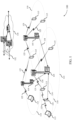
- FIG. 1 illustrates an example of a wireless communications system 100 in accordance with various aspects of the present disclosure.
- the wireless communications system 100 includes base stations 105, UEs 115, and a core network 130.
- the wireless communications system 100 may be a LTE (or LTE-Advanced) network.
- Wireless communications system 100 may operate in an ultra high frequency (UHF) frequency region using frequency bands from 700 MHz to 2600 MHz (2.6 GHz), although in some cases WLAN networks may use frequencies as high as 4 GHz. This region may also be known as the decimeter band, since the wavelengths range from approximately one decimeter to one meter in length.
- UHF waves may propagate mainly by line of sight, and may be blocked by buildings and environmental features. However, the waves may penetrate walls sufficiently to provide service to UEs 115 located indoors. Transmission of UHF waves is characterized by smaller antennas and shorter range (e.g., less than 100 km) compared to transmission using the smaller frequencies (and longer waves) of the high frequency (HF) or very high frequency (VHF) portion of the spectrum.
- HF high frequency
- VHF very high frequency
- wireless communications system 100 may also utilize extremely high frequency (EHF) portions of the spectrum (e.g., from 30 GHz to 300 GHz). This region may also be known as the millimeter band, since the wavelengths range from approximately one millimeter to one centimeter in length.
- EHF antennas may be even smaller and more closely spaced than UHF antennas. In some cases, this may facilitate use of antenna arrays within a UE 115 (e.g., for directional beamforming).
- EHF transmissions may be subject to even greater atmospheric attenuation and shorter range than UHF transmissions.
- Wireless communications system 100 may support millimeter wave (mmW) communications between UEs 115 and base stations 105.
- mmW devices e.g., UEs 115 and base station 105
- a base station 105 may use multiple antennas or antenna arrays to conduct beamforming operations for directional communications with a UE 115.
- Beamforming (which may also be referred to as spatial filtering) is a signal processing technique that may be used at a transmitter (e.g. a base station 105) to shape and/or steer an overall antenna beam in the direction of a target receiver (e.g. a UE 115).
- MIMO multiple-input multiple-output
- base station 105 may have an antenna array with a number of rows and columns of antenna ports that the base station 105 may use for beamforming in its communication with UE 115.
- Synchronization may be performed using synchronization signals or channels transmitted by a synchronization source (e.g., a base station 105). Synchronization signals may include primary synchronization signal (PSS), secondary source signal (SSS), physical broadcast channel (PBCH), etc.
- PSS primary synchronization signal
- SSS secondary source signal
- PBCH physical broadcast channel
- a UE 115 attempting to access a wireless network may perform an initial cell search by detecting a PSS from a base station 105.
- the PSS may enable synchronization of slot timing and may indicate a physical layer identity value.
- the PSS may be utilized to acquire timing and frequency portions of a cell identification (e.g., PCID).
- the UE 115 may then receive an SSS.
- the SSS may enable radio frame synchronization, and may provide a cell identity value, which may be combined with the physical layer identity value to identify the cell.
- the SSS may also enable detection of a duplexing mode and a cyclic prefix length.
- a SSS may be used to acquire the full PCID and other system information (e.g., subframe index).
- the PBCH may be used to acquire additional system information needed for acquisition (e.g., bandwidth, frame index, etc.).
- the UE 115 may receive a MIB, which may be transmitted in a downlink physical channel for broadcast information (e.g., a physical broadcast channel (PBCH)).
- the MIB may contain system bandwidth information, an SFN, and a PHICH configuration. After decoding the MIB, the UE 115 may receive one or more SIBs.
- Synchronization signals may be transmitted multiple times in different directions (e.g., each transmission may be beamformed differently).
- a mmW receiver e.g., a UE 115
- may try multiple beams e.g., antenna subarrays
- Elements of wireless communications system 100 may utilize digital signal processors (DSPs) implementing Fourier transforms.
- DFT discrete Fourier transform
- the discrete frequency representation may be used to map information to subcarriers in the frequency domain.
- an inverse discrete Fourier transform may be used to transform a discrete frequency representation (e.g., information represented in subcarriers) into a discrete time representation (e.g., a signal carrying information in the time domain).
- a transmitter may perform a DFT to map information to subcarriers, and subsequently perform an IDFT to transform the information contained in subcarriers into a signal varying in time to convey the original information.
- Base stations 105 may wirelessly communicate with UEs 115 via one or more base station antennas. Each base station 105 may provide communication coverage for a respective geographic coverage area 110. Communication links 125 shown in wireless communications system 100 may include UL transmissions from a UE 115 to a base station 105, or DL transmissions, from a base station 105 to a UE 115. UEs 115 may be dispersed throughout the wireless communications system 100, and each UE 115 may be stationary or mobile. A UE 115 may also be referred to as a mobile station, a subscriber station, a remote unit, a wireless device, an access terminal (AT), a handset, a user agent, a client, or like terminology. A UE 115 may also be a cellular phone, a wireless modem, a handheld device, a personal computer, a tablet, a personal electronic device, an MTC device, etc.
- Base stations 105 may communicate with the core network 130 and with one another. For example, base stations 105 may interface with the core network 130 through backhaul links 132 (e.g. , S1, etc. ) . Base stations 105 may communicate with one another over backhaul links 134 ( e.g. , X2, etc. ) either directly or indirectly ( e.g ., through core network 130). Base stations 105 may perform radio configuration and scheduling for communication with UEs 115, or may operate under the control of a base station controller (not shown). In some examples, base stations 105 may be macro cells, small cells, hot spots, or the like. Base stations 105 may also be referred to as eNodeBs (eNBs) 105.
- eNodeBs eNodeBs
- the antennas of a base station 105 or UE 115 may be located within one or more antenna arrays.
- One or more base station antennas or antenna arrays may be collocated at an antenna assembly, such as an antenna tower.
- antennas or antenna arrays associated with a base station 105 may be located in diverse geographic locations.
- a base station 105 may multiple use antennas or antenna arrays to conduct beamforming operations for directional communications with a UE 115.
- a UE 115 attempting to access a wireless network may perform an initial cell search by detecting a PSS from a base station 105.
- the PSS may enable synchronization of slot timing and may indicate a physical layer identity value.
- the UE 115 may then receive an SSS.
- the SSS may enable radio frame synchronization, and may provide a cell identity value, which may be combined with the physical layer identity value to identify the cell.
- the SSS may also enable detection of a duplexing mode and a cyclic prefix length.
- Some systems, such as TDD systems may transmit an SSS but not a PSS. Both the PSS and the SSS may be located in the central 62 and 72 subcarriers of a carrier, respectively.
- the UE 115 may receive a MIB, which may be transmitted in the PBCH.
- the MIB may contain system bandwidth information, an SFN, and a PHICH configuration.
- the UE 115 may receive one or more SIBs.
- SIB1 may contain cell access parameters and scheduling information for other SIBs. Decoding SIB1 may enable the UE 115 to receive SIB2.
- SIB2 may contain RRC configuration information related to RACH procedures, paging, PUCCH, PUSCH, power control, SRS, and cell barring.
- FIG. 2 illustrates an example of a wireless communications system 200 supporting optimized secondary synchronization signals.
- wireless communications system 200 may represent aspects of techniques performed by a UE 115 or base station 105 as described with reference to FIG. 1 .
- Wireless communications system 200 may utilize synchronization (sync) signals or channels for beam tracking (e.g., finding the best beam pair between a transmitter and receiver). That is, a synchronization signal (e.g., PSS, SSS, etc.) may be designed to facilitate beam tracking.
- a synchronization signal e.g., PSS, SSS, etc.
- a repeated synchronization signal structure in the time domain may facilitate searching for different beams 205 (e.g., transmitted by base station 105-a) in a timely manner.
- the repeated synchronization signal structure may be achieved by using spacing between a subset of tones or by using a larger tone spacing, and hence having shorter symbol duration and repeating short symbols in the time domain.
- the repeated structure may be further used to encode additional information (e.g., facilitated by the resulting additional degrees of freedom).
- a synchronization signal e.g., SSS
- a signal structure with tone separation in the frequency domain may be configured. That is, separating synchronization signal sample tones by null tones (e.g., empty tones or tones set to zero) may result in a signal with a repeated structure in the time domain.
- null tones e.g., empty tones or tones set to zero
- synchronization signal samples may be mapped to a subset of tones that are K tones apart. That is, out of the available N tones, the synchronization signal may occupy N / K tones while the remaining ( N - N / K ) tones are set to zero (e.g., "0").
- the synchronization signal symbol may consist of a waveform that is repeated K times.
- tone spacing in the frequency domain may result in a shorter symbol in the time domain that can be repeated to achieve a repeating synchronization signal structure in the time domain. That is, the synchronization signal may use larger tone spacing, and hence having shorter symbol duration, compared to other symbols.
- the synchronization signal symbol duration may be reduced by a factor of K , if the tone spacing is increased by a factor of K.
- the resulting short synchronization signal symbol (e.g., with cyclic prefix (CP)) may be repeated K times. Tone spacing may be more widely expressed to having different tone spacings and symbol durations for various synchronization signals (e.g., PSS, SSS, etc.).
- ⁇ f kf 0
- the values for the frequency shifts ⁇ f 0 , f 1 , ..., f K -1 ⁇ may be determined based on the PSS.
- the repeated synchronization signal structure may be used to encode information.
- the N available tones may be divided into K subsets each having N / K tones with K tone separation.
- log2( K ) bits of information may be encoded based on which of the K subsets are used to transmit synchronization signal.
- a K -length cover code may be applied to K short synchronization signal symbols in the time domain.
- X k denote the k th synchronization signal symbol in time domain without cover code
- four possibilities may be: [ X 1 , X 2 , X 3 , X 4 ], [ X 1 , -X 2 , X 3 , -X 4 ], [ X 1 , X 2 , -X 3 , -X 4 ], and [ X 1 , -X 2 ,- X 3 , X 4 ].
- These additional degrees of freedom may be used to encode part of the system information (e.g., symbol/frame number and/or cell id) for which the receiver (e.g., UE 115-a) may use for blind detection.
- the set of tones may be determined using the PSS identification (ID) (e.g., UE 115-a may not employ blind detection) or based on the cell ID.
- ID PSS identification
- UE 115-a may not employ blind detection
- Synchronization signal may be DFT pre-coded to reduce peak to average power ratio (PAPR). That is, a receiver (e.g., UE 115-a) may tune a radio based on the output of an IDFT of a DFT pre-coded synchronization signal. DFT and IDFT may be replaced by a fast Fourier transform (FFT) and inverse fast Fourier transform (IFFT) to allow for receiver algorithms of reduced complexity.
- FFT fast Fourier transform
- IFFT inverse fast Fourier transform
- the synchronization signal base sequence length may be selected to be a power of 2.
- the n -length synchronization signal base sequence may be expanded to the closest power of 2, for example, by cyclic expansion or by tone expansion (e.g., synchronization signal sequence of 62 tones expanded to 64 tones).
- the synchronization signal sequence length being a power of 2 may simplify receiver processing.
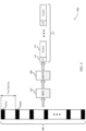
- FIG. 3 illustrates an example of a repeated synchronization signal sequence configuration 300 for optimized secondary synchronization signal.
- repeated synchronization signal sequence configuration 300 may represent aspects of techniques performed by a UE 115 or base station 105 as described with reference to FIG. 1 .
- Frequency region 305 may include N tones in the frequency domain. Each of the N tones may be spaced by a distance f 0 from one another. Frequency region 305 may include synchronization signal sample tones 310 and null tones 315.
- a synchronization signal sample tone 310 may be mapped to one out of every K tones, while the remaining tones are set to zero (e.g., set as null tones 315).
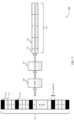
- FIG. 4 illustrates an example of a repeated synchronization signal sequence configuration 400 for optimized secondary synchronization signal.
- repeated synchronization signal sequence configuration 400 may represent aspects of techniques performed by a UE 115 or base station 105 as described with reference to FIG. 1 .
- Frequency region 405 may include N / K tones in the frequency domain. Each of the N / K tones may arise from a tone spacing of Kf 0 between each synchronization signal sample tone 410.
- synchronization signal sample tone 410-a may be spaced a distance of Kf 0 from synchronization signal sample tone 410-b. That is, the N / K synchronization signal sample tones 410 may be spaced and expand the frequency region 405 (e.g., no null tones).
- Time region 425 (e.g., in the time domain) includes the resulting information following the IDFT 415 and CP addition process 420. That is, time region 425 includes CP 430 and synchronization signal symbols 435.
- FIG. 5 illustrates an example of a process flow 600 for optimized secondary synchronization signal.
- process flow 600 may represent aspects of techniques performed by a UE 115 or base station 105 as described with reference to FIG. 1 .
- base station 105-b may generate a synchronization signal (e.g., a SSS) that includes time domain repetitions of a sequence.
- the base station 105-b may further identify information bits, and select a set of tones for transmitting the synchronization signal based on the information bits. In some cases, tones may be identified based on an identifier of an additional synchronization signal of the directional transmission.
- the synchronization signal may include multiple symbols that are a time domain repetition of the sequence.
- base station 105-b may transmit the synchronization signal to UE 115-b.
- the synchronization signal may be transmitted using a directional transmission over mmW spectrum.
- UE 115-b may identify time domain repetitions of a sequence within the synchronization signal.
- UE 115-b may identify tones for receiving the synchronization signal and identify bits of information based on the tones.
- a frequency shift for each of the symbols may be identified based on the identifier of the additional synchronization signal.
- a cover code may be identified for the symbols of the synchronization signal.
- a correlation procedure may be performed on the synchronization signal based on the cover code.
- a cover code may be identified based on a correlation procedure and information bits may be identified based on the cover code.
- UE 115-b may identify a preferred beam direction for communicating with base station 105-b.
- the preferred beam direction may be identified based on attempts to receive the repeated sequence using multiple beams or antenna subarrays.
- UE 115-b may perform a random access channel (RACH) procedure and communicate with base station 105-b via the preferred beam direction identified in step 520.
- RACH random access channel
- FIG. 6 illustrates an example of a process flow 600 for optimized secondary synchronization signal.
- process flow 600 may represent aspects of techniques performed by a UE 115 or base station 105 as described with reference to FIG. 1 .
- base station 105-c may perform a DFT precoding on a synchronization signal. That is, base station 105-c may map the output of the DFT precoding. In some cases, the DFT precoding may include a FFT precoding. At step 610, base station 105-c may perform an IDFT on the output of the DFT (e.g., the output of the subcarrier mapping) performed in step 605 to prepare a synchronization signal for transmission. In some cases, the IDFT may include an IFFT precoding.
- base station 105-c may transmit the output of the IDFT to UE 115-c.
- the output of the IDFT may be transmitted using a directional transmission over mmW spectrum.
- the transmission may include cyclic expansion tone samples.
- UE 115-c may perform a DFT on the received synchronization signal.
- a subcarrier demapping on the output of the DFT may be performed.
- UE 115-c may perform an IDFT on the output of the DFT performed at step 620.
- Performing an IDFT on the output of the DFT may include performing the IDFT on an output of the subcarrier demapping.
- UE 115-c may tune a radio for communication with base station 105-c based on the output of the IDFT.
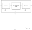
- FIG. 7 shows a block diagram 700 of a wireless device 705 that supports optimized secondary synchronization signal in accordance with various aspects of the present disclosure.
- Wireless device 705 may be an example of aspects of a UE 115 as described with reference to FIG. 1 .
- Wireless device 705 may include receiver 710, UE communication manager 715, and transmitter 720.
- Wireless device 705 may also include a processor. Each of these components may be in communication with one another ( e.g ., via one or more buses).
- Receiver 710 may receive information such as packets, user data, or control information associated with various information channels (e.g ., control channels, data channels, and information related to optimized secondary synchronization signal, etc. ). Information may be passed on to other components of the device.
- the receiver 710 may be an example of aspects of the transceiver 1035 described with reference to FIG. 10 .
- Receiver 710 may receive a synchronization signal.
- the synchronization signal is received in a directional transmission.
- the directional transmission includes a millimeter wave (mmW) transmission.
- the synchronization signal is a secondary synchronization signal (SSS).
- UE communication manager 715 may be an example of aspects of the UE communication manager 1015 described with reference to FIG. 10 .
- UE communication manager 715 may identify a set of time domain repetitions of a sequence within the synchronization signal, identify a preferred beam direction for communicating with the base station based on the set of repetitions of the sequence, perform a discrete Fourier transform (DFT) on the synchronization signal, perform an inverse discrete Fourier transform (IDFT) on an output of the DFT, and tune a radio based on the output of the IDFT.
- DFT discrete Fourier transform
- IDFT inverse discrete Fourier transform
- Transmitter 720 may transmit signals generated by other components of the device.
- the transmitter 720 may be collocated with a receiver 710 in a transceiver module.
- the transmitter 720 may be an example of aspects of the transceiver 1035 described with reference to FIG. 10 .
- the transmitter 720 may include a single antenna, or it may include a set of antennas.
- FIG. 8 shows a block diagram 800 of a Wireless device 805 that supports optimized secondary synchronization signal in accordance with various aspects of the present disclosure.
- Wireless device 805 may be an example of aspects of a wireless device 705 or a UE 115 as described with reference to FIGs. 1 and 7 .
- Wireless device 805 may include receiver 810, UE communication manager 815, and transmitter 820.
- Wireless device 805 may also include a processor. Each of these components may be in communication with one another ( e.g ., via one or more buses).
- Receiver 810 may receive information such as packets, user data, or control information associated with various information channels (e.g ., control channels, data channels, and information related to optimized secondary synchronization signal, etc. ) . Information may be passed on to other components of the device.
- the receiver 810 may be an example of aspects of the transceiver 1035 described with reference to FIG. 10 .
- UE communication manager 815 may be an example of aspects of the UE communication manager 1015 described with reference to FIG. 10 .
- UE communication manager 815 may also include repeated sequence component 825, beam direction component 830, DFT component 835, IDFT component 840, and synchronization component 845.
- Repeated sequence component 825 may identify a set of time domain repetitions of a sequence within the synchronization signal.
- the synchronization signal includes a set of symbols, where each of the set of symbols includes a time domain repetition of the sequence
- Beam direction component 830 may identify a preferred beam direction for communicating with the base station based on the set of repetitions of the sequence.
- DFT component 835 may perform a discrete Fourier transform (DFT) on the synchronization signal.
- IDFT component 840 may perform an inverse discrete Fourier transform (IDFT) on an output of the DFT and identify one or more expansion tone samples of the synchronization signal, where the IFFT is based on the one or more expansion tone samples.
- the DFT includes a fast Fourier transform (FFT) or the IDFT includes an inverse fast Fourier transform (IFFT).
- the one or more expansion tone samples include one or more cyclic expansion tone samples.
- Synchronization component 845 may tune a radio based on the output of the IDFT.
- Transmitter 820 may transmit signals generated by other components of the device.
- the transmitter 820 may be collocated with a receiver 810 in a transceiver module.
- the transmitter 820 may be an example of aspects of the transceiver 1035 described with reference to FIG. 10 .
- the transmitter 820 may include a single antenna, or it may include a set of antennas.
- FIG. 9 shows a block diagram 900 of a UE communication manager 915 that supports optimized secondary synchronization signal in accordance with various aspects of the present disclosure.
- the UE communication manager 915 may be an example of aspects of a UE communication manager 715, a UE communication manager 815, or a UE communication manager 1015 described with reference to FIGs. 7 , 8 , and 10 .
- the UE communication manager 915 may include repeated sequence component 920, beam direction component 925, DFT component 930, IDFT component 935, synchronization component 940, tone spacing component 945, frequency shift component 950, cover code component 955, and demapping component 960. Each of these modules may communicate, directly or indirectly, with one another ( e.g ., via one or more buses).
- Repeated sequence component 920 may identify a set of time domain repetitions of a sequence within the synchronization signal.
- the synchronization signal includes a set of symbols, where each of the set of symbols includes a time domain repetition of the sequence
- Beam direction component 925 may identify a preferred beam direction for communicating with the base station based on the set of repetitions of the sequence.
- DFT component 930 may perform a discrete Fourier transform (DFT) on the synchronization signal.
- IDFT component 935 may perform an inverse discrete Fourier transform (IDFT) on an output of the DFT and identify one or more expansion tone samples of the synchronization signal, where the IFFT is based on the one or more expansion tone samples.
- the DFT includes a fast Fourier transform (FFT) or the IDFT includes an inverse fast Fourier transform (IFFT).
- the one or more expansion tone samples include one or more cyclic expansion tone samples.
- Synchronization component 940 may tune a radio based on the output of the IDFT.
- Tone spacing component 945 may identify a set of tones for receiving the synchronization signal, where the synchronization signal is received using a subset of the set of tones and includes a single symbol that includes the set of time domain repetitions of the sequence, identify one or more bits of information based on the subset of the set tones, and identify the subset of the set of tones based on an identifier of an additional synchronization signal of the directional transmission.
- the subset of the set of tones includes a subset of equidistant tones separated by a subset of empty tones that are not used to transmit the synchronization signal.
- the synchronization signal includes a tone spacing that is greater than a tone spacing of an additional signal of a transmission and a symbol duration that is less than a symbol duration of an additional signal.
- Frequency shift component 950 may identify the frequency shift for each of the set of symbols based on an identifier of the additional signal. In some cases, each of the set of symbols is received using a frequency shift that is different from a frequency shift for at least one symbol of the set of symbols.
- Cover code component 955 may identify a cover code for the set of symbols of the synchronization signal, perform a correlation procedure on the synchronization signal based on the cover code, identify a cover code for the set of symbols of the synchronization signal based on a correlation procedure, and identify one or more bits of information based on the cover code.
- the cover code is identified based on an identifier of a previous synchronization signal.
- Demapping component 960 may perform a subcarrier demapping on the output of the DFT, where performing the IDFT on the output of the DFT includes performing the IDFT on an output of the subcarrier demapping.
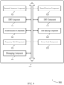
- FIG. 10 shows a diagram of a system 1000 including a device 1005 that supports optimized secondary synchronization signal in accordance with various aspects of the present disclosure.
- Device 1005 may be an example of or include the components of wireless device 705, wireless device 805, or a UE 115 as described above, e.g ., with reference to FIGs. 1 , 7 and 8 .
- Device 1005 may include components for bi-directional voice and data communications including components for transmitting and receiving communications, including UE communication manager 1015, processor 1020, memory 1025, software 1030, transceiver 1035, antenna 1040, and I/O controller 1045.
- Processor 1020 may include an intelligent hardware device, (e.g ., a general-purpose processor, a digital signal processor (DSP), a central processing unit (CPU), a microcontroller, an application specific integrated circuit (ASIC), a field-programmable gate array (FPGA), a programmable logic device, a discrete gate or transistor logic component, a discrete hardware component, or any combination thereof).
- processor 1020 may be configured to operate a memory array using a memory controller.
- a memory controller may be integrated into processor 1020.
- Processor 1020 may be configured to execute computer-readable instructions stored in a memory to perform various functions (e.g., function or tasks supporting optimized secondary synchronization signal). 1020.
- Memory 1025 may include random access memory (RAM) and read only memory (ROM).
- the memory 1025 may store computer-readable, computer-executable software 1030 including instructions that, when executed, cause the processor to perform various functions described herein.
- the memory 1025 can contain, among other things, a Basic Input-Output system (BIOS) which may control basic hardware and/or software operation such as the interaction with peripheral components or devices.
- BIOS Basic Input-Output system
- Software 1030 may include code to implement aspects of the present disclosure, including code to support optimized secondary synchronization signal.
- Software 1030 can be stored in a non-transitory computer-readable medium such as system memory or other memory. In some cases, the software 1030 may not be directly executable by the processor but may cause a computer ( e.g ., when compiled and executed) to perform functions described herein.
- Transceiver 1035 may communicate bi-directionally, via one or more antennas, wired, or wireless links as described above.
- the transceiver 1035 may represent a wireless transceiver and may communicate bi-directionally with another wireless transceiver.
- the transceiver 1035 may also include a modem to modulate the packets and provide the modulated packets to the antennas for transmission, and to demodulate packets received from the antennas.
- the wireless device may include a single antenna 1040. However, in some cases the device may have more than one antenna 1040, which may be capable of concurrently transmitting or receiving multiple wireless transmissions.
- I/O controller 1045 may manage input and output signals for device 1005. Input/output control component 1045 may also manage peripherals not integrated into device 1005. In some cases, input/output control component 1045 may represent a physical connection or port to an external peripheral. In some cases, I/O controller 1045 may utilize an operating system such as iOS ® , ANDROID ® , MS-DOS ® , MS-WINDOWS ® , OS/2 ® , UNIX ® , LINUX ® , or another known operating system.
- an operating system such as iOS ® , ANDROID ® , MS-DOS ® , MS-WINDOWS ® , OS/2 ® , UNIX ® , LINUX ® , or another known operating system.
- FIG. 11 shows a block diagram 1100 of a wireless device 1105 that supports optimized secondary synchronization signal in accordance with various aspects of the present disclosure.
- Wireless device 1105 may be an example of aspects of a base station 105 as described with reference to FIG. 1 .
- Wireless device 1105 may include receiver 1110, base station communication manager 1115, and transmitter 1120.
- Wireless device 1105 may also include a processor. Each of these components may be in communication with one another ( e.g ., via one or more buses).
- Receiver 1110 may receive information such as packets, user data, or control information associated with various information channels (e.g ., control channels, data channels, and information related to optimized secondary synchronization signal, etc. ) . Information may be passed on to other components of the device.
- the receiver 1110 may be an example of aspects of the transceiver 1435 described with reference to FIG. 14 .
- Base station communication manager 1115 may be an example of aspects of the base station communication manager 1415 described with reference to FIG. 14 .
- Base station communication manager 1115 may generate a synchronization signal, where the synchronization signal includes a set of time domain repetitions of a sequence, generate a synchronization signal, perform a discrete Fourier transform (DFT) precoding on the synchronization signal, and perform an inverse discrete Fourier transform (IDFT) on an output of the DFT precoding.
- DFT discrete Fourier transform
- IDFT inverse discrete Fourier transform
- Transmitter 1120 may transmit signals generated by other components of the device.
- the transmitter 1120 may be collocated with a receiver 1110 in a transceiver module.
- the transmitter 1120 may be an example of aspects of the transceiver 1435 described with reference to FIG. 14 .
- the transmitter 1120 may include a single antenna, or it may include a set of antennas.
- Transmitter 1120 may transmit the synchronization signal to a UE and transmit an output of the IDFT to a UE.
- the synchronization signal is transmitted in a directional transmission.
- the directional transmission includes a millimeter wave (mmW) transmission.
- the synchronization signal is a secondary synchronization signal (SSS).
- FIG. 12 shows a block diagram 1200 of a Wireless device 1205 that supports optimized secondary synchronization signal in accordance with various aspects of the present disclosure.
- Wireless device 1205 may be an example of aspects of a wireless device 1105 or a base station 105 as described with reference to FIGs. 1 and 11 .
- Wireless device 1205 may include receiver 1210, base station communication manager 1215, and transmitter 1220.
- Wireless device 1205 may also include a processor. Each of these components may be in communication with one another ( e.g ., via one or more buses).
- Receiver 1210 may receive information such as packets, user data, or control information associated with various information channels (e.g ., control channels, data channels, and information related to optimized secondary synchronization signal, etc. ) . Information may be passed on to other components of the device.
- the receiver 1210 may be an example of aspects of the transceiver 1435 described with reference to FIG. 14 .
- Base station communication manager 1215 may be an example of aspects of the base station communication manager 1415 described with reference to FIG. 14 .
- Base station communication manager 1215 may also include synchronization signal component 1225, DFT component 1230, and IDFT component 1235.
- Synchronization signal component 1225 may generate a synchronization signal, where the synchronization signal includes a set of time domain repetitions of a sequence and generate a synchronization signal. In some cases, the synchronization signal includes a single symbol including the set of time domain repetitions of the sequence.
- DFT component 1230 may perform a discrete Fourier transform (DFT) precoding on the synchronization signal and append one or more expansion tone samples to the synchronization signal, where the FFT precoding or the IDFT is based on the one or more expansion tone samples.
- DFT precoding includes a fast Fourier transform (FFT) precoding or the IDFT includes an inverse fast Fourier transform (IFFT).
- IFFT inverse fast Fourier transform
- the one or more expansion tone samples include one or more cyclic expansion tone samples.
- IDFT component 1235 may perform an inverse discrete Fourier transform (IDFT) on an output of the DFT precoding.
- IDFT inverse discrete Fourier transform
- Transmitter 1220 may transmit signals generated by other components of the device.
- the transmitter 1220 may be collocated with a receiver 1210 in a transceiver module.
- the transmitter 1220 may be an example of aspects of the transceiver 1435 described with reference to FIG. 14 .
- the transmitter 1220 may include a single antenna, or it may include a set of antennas.
- FIG. 13 shows a block diagram 1300 of a base station communication manager 1315 that supports optimized secondary synchronization signal in accordance with various aspects of the present disclosure.
- the base station communication manager 1315 may be an example of aspects of a base station communication manager 1415 described with reference to FIGs. 11 , 12 , and 14 .
- the base station communication manager 1315 may include synchronization signal component 1320, DFT component 1325, IDFT component 1330, tone spacing component 1335, repeated sequence component 1340, frequency shift component 1345, cover code component 1350, and subcarrier mapping component 1355. Each of these modules may communicate, directly or indirectly, with one another ( e.g ., via one or more buses).
- Synchronization signal component 1320 may generate a synchronization signal, where the synchronization signal includes a set of time domain repetitions of a sequence and generate a synchronization signal.
- the synchronization signal includes a single symbol including the set of time domain repetitions of the sequence.
- DFT component 1325 may perform a discrete Fourier transform (DFT) precoding on the synchronization signal and append one or more expansion tone samples to the synchronization signal, where the FFT precoding or the IDFT is based on the one or more expansion tone samples.
- DFT precoding includes a fast Fourier transform (FFT) precoding or the IDFT includes an inverse fast Fourier transform (IFFT).
- IFFT inverse fast Fourier transform
- the one or more expansion tone samples include one or more cyclic expansion tone samples.
- IDFT component 1330 may perform an inverse discrete Fourier transform (IDFT) on an output of the DFT precoding.
- IDFT inverse discrete Fourier transform
- Tone spacing component 1335 may identify a set of tones for transmitting the synchronization signal, identify one or more information bits, and select a subset of the set of tones based on the one or more information bits, where the synchronization signal is transmitted using the subset of the set of tones.
- the subset of the set of tones includes a subset of equidistant tones separated by a subset of empty tones that are not used to transmit the synchronization signal.
- the synchronization signal includes a tone spacing that is greater than a tone spacing of an additional signal of a transmission and a symbol duration that is less than a symbol duration of an additional signal.
- Repeated sequence component 1340 may generate a subsequence to be repeated within a synchronization signal.
- the synchronization signal includes a set of symbols, where each of the set of symbols includes a time domain repetition of the sequence.
- Frequency shift component 1345 may identify the frequency shift for each of the set of symbols based on an identifier of the additional synchronization signal. In some cases, each of the set of symbols is transmitted using a frequency shift that is different from a frequency shift for at least one symbol of the set of symbols.
- Cover code component 1350 may select a cover code for the set of symbols of the synchronization signal, where the synchronization signal is transmitted based on the cover code and identify one or more information bits for the UE, where the cover code is selected based on the one or more information bits.
- Subcarrier mapping component 1355 may perform a subcarrier mapping on the output of the DFT precoding, where performing the IDFT on the output of the DFT precoding includes performing the IDFT on an output of the subcarrier mapping.
- FIG. 14 shows a diagram of a system 1400 including a device 1405 that supports optimized secondary synchronization signal in accordance with various aspects of the present disclosure.
- Device 1405 may be an example of or include the components of a base station 105 as described above, e.g., with reference to FIG. 1 .
- Device 1405 may include components for bi-directional voice and data communications including components for transmitting and receiving communications, including base station communication manager 1415, processor 1420, memory 1425, software 1430, transceiver 1435, antenna 1440, network communications manager 1445, and base station communications manager 1450.
- Processor 1420 may include an intelligent hardware device, (e.g ., a general-purpose processor, a digital signal processor (DSP), a central processing unit (CPU), a microcontroller, an application specific integrated circuit (ASIC), a field-programmable gate array (FPGA), a programmable logic device, a discrete gate or transistor logic component, a discrete hardware component, or any combination thereof).
- processor 1420 may be configured to operate a memory array using a memory controller.
- a memory controller may be integrated into processor 1420.
- Processor 1420 may be configured to execute computer-readable instructions stored in a memory to perform various functions (e.g ., function or tasks supporting optimized secondary synchronization signal). 1420.
- Memory 1425 may include random access memory (RAM) and read only memory (ROM).
- the memory 1425 may store computer-readable, computer-executable software 1430 including instructions that, when executed, cause the processor to perform various functions described herein.
- the memory 1425 can contain, among other things, a Basic Input-Output system (BIOS) which may control basic hardware and/or software operation such as the interaction with peripheral components or devices.
- BIOS Basic Input-Output system
- Software 1430 may include code to implement aspects of the present disclosure, including code to support optimized secondary synchronization signal.
- Software 1430 can be stored in a non-transitory computer-readable medium such as system memory or other memory. In some cases, the software 1430 may not be directly executable by the processor but may cause a computer ( e.g ., when compiled and executed) to perform functions described herein.
- Transceiver 1435 may communicate bi-directionally, via one or more antennas, wired, or wireless links as described above.
- the transceiver 1435 may represent a wireless transceiver and may communicate bi-directionally with another wireless transceiver.
- the transceiver 1435 may also include a modem to modulate the packets and provide the modulated packets to the antennas for transmission, and to demodulate packets received from the antennas.
- the wireless device may include a single antenna 1440. However, in some cases the device may have more than one antenna 1440, which may be capable of concurrently transmitting or receiving multiple wireless transmissions.
- Network communications manager 1445 may manage communications with the core network ( e.g ., via one or more wired backhaul links). For example, the network communications module 1445 may manage the transfer of data communications for client devices, such as one or more UEs 115.
- Base station communications manager 1450 may manage communications with other base station 105, and may include a controller or scheduler for controlling communications with UEs 115 in cooperation with other base stations 105. For example, the base station communications manager 1450 may coordinate scheduling for transmissions to UEs 115 for various interference mitigation techniques such as beamforming or joint transmission. In some examples, base station communications manager 1450 may provide an X2 interface within an LTE/LTE-A wireless communication network technology to provide communication between base stations 105.
- FIG. 15 shows a flowchart illustrating a method 1500 for optimized secondary synchronization signal in accordance with various aspects of the present disclosure.
- the operations of method 1500 may be implemented by a UE 115 or its components as described herein.
- the operations of method 1500 may be performed by a UE communication manager as described with reference to FIGs. 7 through 10 .
- a UE 115 may execute a set of codes to control the functional elements of the device to perform the functions described below. Additionally or alternatively, the UE 115 may perform aspects the functions described below using special-purpose hardware.
- the UE 115 may receive a synchronization signal.
- the operations of block 1505 may be performed according to the methods described with reference to FIGs. 1 through 6 . In certain examples, aspects of the operations of block 1505 may be performed by a receiver as described with reference to FIGs. 7 through 10 .
- the UE 115 may identify a set of time domain repetitions of a sequence within the synchronization signal.
- the operations of block 1510 may be performed according to the methods described with reference to FIGs. 1 through 6 . In certain examples, aspects of the operations of block 1510 may be performed by a repeated sequence component as described with reference to FIGs. 7 through 10 .
- the UE 115 may identify a preferred beam direction for communicating with the base station based on the set of repetitions of the sequence.
- the operations of block 1515 may be performed according to the methods described with reference to FIGs. 1 through 6 . In certain examples, aspects of the operations of block 1515 may be performed by a beam direction component as described with reference to FIGs. 7 through 10 .
- FIG. 16 shows a flowchart illustrating a method 1600 for optimized secondary synchronization signal in accordance with various aspects of the present disclosure.
- the operations of method 1600 may be implemented by a UE 115 or its components as described herein.
- the operations of method 1600 may be performed by a UE communication manager as described with reference to FIGs. 7 through 10 .
- a UE 115 may execute a set of codes to control the functional elements of the device to perform the functions described below. Additionally or alternatively, the UE 115 may perform aspects the functions described below using special-purpose hardware.
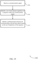
- the UE 115 may identify a set of tones for receiving a synchronization signal, where the synchronization signal is received using a subset of the set of tones and includes a single symbol that includes the set of time domain repetitions of the sequence.
- the operations of block 1605 may be performed according to the methods described with reference to FIGs. 1 through 6 . In certain examples, aspects of the operations of block 1605 may be performed by a tone spacing component as described with reference to FIGs. 7 through 10 .
- the UE 115 may receive the synchronization signal.
- the operations of block 1610 may be performed according to the methods described with reference to FIGs. 1 through 6 . In certain examples, aspects of the operations of block 1610 may be performed by a receiver as described with reference to FIGs. 7 through 10 .
- the UE 115 may identify a set of time domain repetitions of a sequence within the synchronization signal.
- the operations of block 1615 may be performed according to the methods described with reference to FIGs. 1 through 6 . In certain examples, aspects of the operations of block 1615 may be performed by a repeated sequence component as described with reference to FIGs. 7 through 10 .
- the UE 115 may identify a preferred beam direction for communicating with the base station based on the set of repetitions of the sequence.
- the operations of block 1620 may be performed according to the methods described with reference to FIGs. 1 through 6 . In certain examples, aspects of the operations of block 1620 may be performed by a beam direction component as described with reference to FIGs. 7 through 10 .
- FIG. 17 shows a flowchart illustrating a method 1700 for optimized secondary synchronization signal in accordance with various aspects of the present disclosure.
- the operations of method 1700 may be implemented by a UE 115 or its components as described herein.
- the operations of method 1700 may be performed by a UE communication manager as described with reference to FIGs. 7 through 10 .
- a UE 115 may execute a set of codes to control the functional elements of the device to perform the functions described below. Additionally or alternatively, the UE 115 may perform aspects the functions described below using special-purpose hardware.
- the UE 115 may receive a synchronization signal and an additional synchronization signal in a directional transmission.
- the synchronization signal includes a tone spacing that is greater than a tone spacing of the additional signal of and a symbol duration that is less than a symbol duration of an additional signal.
- the operations of block 1705 may be performed according to the methods described with reference to FIGs. 1 through 6 . In certain examples, aspects of the operations of block 1705 may be performed by a receiver as described with reference to FIGs. 7 through 10 .
- the UE 115 may identify a set of time domain repetitions of a sequence within the synchronization signal.
- the operations of block 1710 may be performed according to the methods described with reference to FIGs. 1 through 6 . In certain examples, aspects of the operations of block 1710 may be performed by a repeated sequence component as described with reference to FIGs. 7 through 10 .
- the UE 115 may identify a preferred beam direction for communicating with the base station based on the set of repetitions of the sequence.
- the operations of block 1715 may be performed according to the methods described with reference to FIGs. 1 through 6 . In certain examples, aspects of the operations of block 1715 may be performed by a beam direction component as described with reference to FIGs. 7 through 10 .
- FIG. 18 shows a flowchart illustrating a method 1800 for optimized secondary synchronization signal in accordance with various aspects of the present disclosure.
- the operations of method 1800 may be implemented by a UE 115 or its components as described herein.
- the operations of method 1800 may be performed by a UE communication manager as described with reference to FIGs. 7 through 10 .
- a UE 115 may execute a set of codes to control the functional elements of the device to perform the functions described below. Additionally or alternatively, the UE 115 may perform aspects the functions described below using special-purpose hardware.
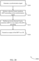
- the UE 115 may receive a synchronization signal.
- the operations of block 1805 may be performed according to the methods described with reference to FIGs. 1 through 6 . In certain examples, aspects of the operations of block 1805 may be performed by a receiver as described with reference to FIGs. 7 through 10 .
- the UE 115 may perform a discrete Fourier transform (DFT) on the synchronization signal.
- DFT discrete Fourier transform
- the operations of block 1810 may be performed according to the methods described with reference to FIGs. 1 through 6 . In certain examples, aspects of the operations of block 1810 may be performed by a DFT component as described with reference to FIGs. 7 through 10 .
- the UE 115 may perform an inverse discrete Fourier transform (IDFT) on an output of the DFT.
- IDFT inverse discrete Fourier transform
- the operations of block 1815 may be performed according to the methods described with reference to FIGs. 1 through 6 . In certain examples, aspects of the operations of block 1815 may be performed by a IDFT component as described with reference to FIGs. 7 through 10 .
- the UE 115 may tune a radio based on the output of the IDFT.
- the operations of block 1820 may be performed according to the methods described with reference to FIGs. 1 through 6 . In certain examples, aspects of the operations of block 1820 may be performed by a synchronization component as described with reference to FIGs. 7 through 10 .
- FIG. 19 shows a flowchart illustrating a method 1900 for optimized secondary synchronization signal in accordance with various aspects of the present disclosure.
- the operations of method 1900 may be implemented by a base station 105 or its components as described herein.
- the operations of method 1900 may be performed by a base station communication manager as described with reference to FIGs. 11 through 14 .
- a base station 105 may execute a set of codes to control the functional elements of the device to perform the functions described below. Additionally or alternatively, the base station 105 may perform aspects the functions described below using special-purpose hardware.
- the base station 105 may generate a synchronization signal, where the synchronization signal includes a set of time domain repetitions of a sequence.
- the operations of block 1905 may be performed according to the methods described with reference to FIGs. 1 through 6 . In certain examples, aspects of the operations of block 1905 may be performed by a synchronization signal component as described with reference to FIGs. 11 through 14 .
- the base station 105 may transmit the synchronization signal to a UE.
- the operations of block 1910 may be performed according to the methods described with reference to FIGs. 1 through 6 . In certain examples, aspects of the operations of block 1910 may be performed by a transmitter as described with reference to FIGs. 11 through 14 .
- FIG. 20 shows a flowchart illustrating a method 2000 for optimized secondary synchronization signal in accordance with various aspects of the present disclosure.
- the operations of method 2000 may be implemented by a base station 105 or its components as described herein.
- the operations of method 2000 may be performed by a base station communication manager as described with reference to FIGs. 11 through 14 .
- a base station 105 may execute a set of codes to control the functional elements of the device to perform the functions described below. Additionally or alternatively, the base station 105 may perform aspects the functions described below using special-purpose hardware.
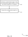
- the base station 105 may generate a synchronization signal.
- the operations of block 2005 may be performed according to the methods described with reference to FIGs. 1 through 6 .
- aspects of the operations of block 2005 may be performed by a synchronization signal component as described with reference to FIGs. 11 through 14 .
- the base station 105 may perform a discrete Fourier transform (DFT) precoding on the synchronization signal.
- DFT discrete Fourier transform
- the operations of block 2010 may be performed according to the methods described with reference to FIGs. 1 through 6 . In certain examples, aspects of the operations of block 2010 may be performed by a DFT component as described with reference to FIGs. 11 through 14 .
- the base station 105 may perform an inverse discrete Fourier transform (IDFT) on an output of the DFT precoding.
- IDFT inverse discrete Fourier transform
- the operations of block 2015 may be performed according to the methods described with reference to FIGs. 1 through 6 .
- aspects of the operations of block 2015 may be performed by a IDFT component as described with reference to FIGs. 11 through 14 .
- the base station 105 may transmit an output of the IDFT to a UE.
- the operations of block 2020 may be performed according to the methods described with reference to FIGs. 1 through 6 . In certain examples, aspects of the operations of block 2020 may be performed by a transmitter as described with reference to FIGs. 11 through 14 .
- CDMA code division multiple access
- TDMA time division multiple access
- FDMA frequency division multiple access
- OFDMA orthogonal frequency division multiple access
- SC-FDMA single carrier frequency division multiple access
- CDMA2000 covers IS-2000, IS-95, and IS-856 standards.
- IS-2000 Releases may be commonly referred to as CDMA2000 1X, 1X, etc.
- IS-856 (TIA-856) is commonly referred to as CDMA2000 1xEV-DO, High Rate Packet Data (HRPD), etc.
- UTRA includes Wideband CDMA (WCDMA) and other variants of CDMA.
- WCDMA Wideband CDMA
- a time division multiple access (TDMA) system may implement a radio technology such as Global System for Mobile Communications (GSM).
- GSM Global System for Mobile Communications
- An orthogonal frequency division multiple access (OFDMA) system may implement a radio technology such as Ultra Mobile Broadband (UMB), Evolved UTRA (E-UTRA), IEEE 802.11 (Wi-Fi), IEEE 802.16 (WiMAX), IEEE 802.20, Flash-OFDM, etc.
- UMB Ultra Mobile Broadband
- E-UTRA Evolved UTRA
- IEEE 802.11 Wi-Fi
- IEEE 802.16 WiMAX
- IEEE 802.20 Flash-OFDM
- UMB Ultra Mobile Broadband
- E-UTRA Evolved UTRA
- Wi-Fi Wi-Fi
- WiMAX IEEE 802.16
- Flash-OFDM Flash-OFDM
- UTRA and E-UTRA are part of Universal Mobile Telecommunications system (UMTS).
- 3GPP Long Term Evolution (LTE) and LTE-Advanced (LTE-A) are new releases of Universal Mobile Telecommunications System (UMTS) that use E-UTRA.
- CDMA2000 and UMB are described in documents from an organization named "3rd Generation Partnership Project 2" (3GPP2).
- 3GPP2 3rd Generation Partnership Project 2
- the techniques described herein may be used for the systems and radio technologies mentioned above as well as other systems and radio technologies. While aspects an LTE system may be described for purposes of example, and LTE terminology may be used in much of the description, the techniques described herein are applicable beyond LTE applications.
- the term evolved node B may be generally used to describe the base stations.
- the wireless communications system or systems described herein may include a heterogeneous LTE/LTE-A network in which different types of evolved node B (eNBs) provide coverage for various geographical regions.
- eNBs evolved node B
- each eNB or base station may provide communication coverage for a macro cell, a small cell, or other types of cell.
- the term "cell” can be used to describe a base station, a carrier or component carrier associated with a base station, or a coverage area ( e.g., sector, etc. ) of a carrier or base station, depending on context.
- Base stations may include or may be referred to by those skilled in the art as a base transceiver station, a radio base station, an access point, a radio transceiver, a NodeB, eNodeB (eNB), Home NodeB, a Home eNodeB, or some other suitable terminology.
- the geographic coverage area for a base station may be divided into sectors making up only a portion of the coverage area.
- the wireless communications system or systems described herein may include base stations of different types (e.g ., macro or small cell base stations).
- the UEs described herein may be able to communicate with various types of base stations and network equipment including macro eNBs, small cell eNBs, relay base stations, and the like. There may be overlapping geographic coverage areas for different technologies.
- a macro cell generally covers a relatively large geographic area (e.g ., several kilometers in radius) and may allow unrestricted access by UEs with service subscriptions with the network provider.
- a small cell is a lower-powered base station, as compared with a macro cell, that may operate in the same or different ( e.g ., licensed, unlicensed, etc. ) frequency bands as macro cells.
- Small cells may include pico cells, femto cells, and micro cells according to various examples.
- a pico cell for example, may cover a small geographic area and may allow unrestricted access by UEs with service subscriptions with the network provider.
- a femto cell may also cover a small geographic area (e.g ., a home) and may provide restricted access by UEs having an association with the femto cell (e.g ., UEs in a closed subscriber group (CSG), UEs for users in the home, and the like).
- An eNB for a macro cell may be referred to as a macro eNB.
- An eNB for a small cell may be referred to as a small cell eNB, a pico eNB, a femto eNB, or a home eNB.
- An eNB may support one or multiple ( e.g., two, three, four, and the like) cells ( e.g ., component carriers).
- a UE may be able to communicate with various types of base stations and network equipment including macro eNBs, small cell eNBs, relay base stations, and the like.
- the wireless communications system or systems described herein may support synchronous or asynchronous operation.
- the base stations may have similar frame timing, and transmissions from different base stations may be approximately aligned in time.
- the base stations may have different frame timing, and transmissions from different base stations may not be aligned in time.
- the techniques described herein may be used for either synchronous or asynchronous operations.
- Information and signals described herein may be represented using any of a variety of different technologies and techniques.
- data, instructions, commands, information, signals, bits, symbols, and chips that may be referenced throughout the above description may be represented by voltages, currents, electromagnetic waves, magnetic fields or particles, optical fields or particles, or any combination thereof.
- a general-purpose processor may be a microprocessor, but in the alternative, the processor may be any conventional processor, controller, microcontroller, or state machine.
- a processor may also be implemented as a combination of computing devices (e.g., a combination of a digital signal processor (DSP) and a microprocessor, multiple microprocessors, one or more microprocessors in conjunction with a DSP core, or any other such configuration).
- DSP digital signal processor
- the functions described herein may be implemented in hardware, software executed by a processor, firmware, or any combination thereof. If implemented in software executed by a processor, the functions may be stored on or transmitted over as one or more instructions or code on a computer-readable medium. Other examples and implementations are within the scope of the disclosure and appended claims. For example, due to the nature of software, functions described above can be implemented using software executed by a processor, hardware, firmware, hardwiring, or combinations of any of these. Features implementing functions may also be physically located at various positions, including being distributed such that portions of functions are implemented at different physical locations.
- Computer-readable media includes both non-transitory computer storage media and communication media including any medium that facilitates transfer of a computer program from one place to another.
- a non-transitory storage medium may be any available medium that can be accessed by a general purpose or special purpose computer.
- non-transitory computer-readable media can comprise RAM, ROM, electrically erasable programmable read only memory (EEPROM), compact disk (CD) ROM or other optical disk storage, magnetic disk storage or other magnetic storage devices, or any other non-transitory medium that can be used to carry or store desired program code means in the form of instructions or data structures and that can be accessed by a general-purpose or special-purpose computer, or a general-purpose or special-purpose processor.
- RAM random access memory
- ROM read only memory
- EEPROM electrically erasable programmable read only memory
- CD compact disk
- magnetic disk storage or other magnetic storage devices or any other non-transitory medium that can be used to carry or store desired program code means in the form of instructions or data structures
- any connection is properly termed a computer-readable medium.
- the software is transmitted from a website, server, or other remote source using a coaxial cable, fiber optic cable, twisted pair, digital subscriber line (DSL), or wireless technologies such as infrared, radio, and microwave
- the coaxial cable, fiber optic cable, twisted pair, digital subscriber line (DSL), or wireless technologies such as infrared, radio, and microwave are included in the definition of medium.
- Disk and disc include CD, laser disc, optical disc, digital versatile disc (DVD), floppy disk and Blu-ray disc where disks usually reproduce data magnetically, while discs reproduce data optically with lasers. Combinations of the above are also included within the scope of computer-readable media.
Landscapes
- Engineering & Computer Science (AREA)
- Signal Processing (AREA)
- Computer Networks & Wireless Communication (AREA)
- Databases & Information Systems (AREA)
- Physics & Mathematics (AREA)
- Mathematical Physics (AREA)
- Discrete Mathematics (AREA)
- General Physics & Mathematics (AREA)
- Mobile Radio Communication Systems (AREA)
Description
- The following relates generally to wireless communication, and more specifically to optimized secondary synchronization signal.
- Wireless communications systems are widely deployed to provide various types of communication content such as voice, video, packet data, messaging, broadcast, and so on. These systems may be capable of supporting communication with multiple users by sharing the available system resources (e.g., time, frequency, and power). Examples of such multiple-access systems include code division multiple access (CDMA) systems, time division multiple access (TDMA) systems, frequency division multiple access (FDMA) systems, and orthogonal frequency division multiple access (OFDMA) systems, (e.g., a Long Term Evolution (LTE) system). A wireless multiple-access communications system may include a number of base stations, each simultaneously supporting communication for multiple communication devices, which may be otherwise known as user equipment (UE).
- Wireless communications systems operating in millimeter wave (mmW) spectrum may employ beamforming. Synchronization signals (e.g., primary synchronization signals (PSS), secondary synchronization signals (SSS), etc.), beam reference signals, and/or control signals may be transmitted multiple times in different directions (e.g., each transmission may be beamformed differently). Communicating using a suboptimal beam direction (e.g., antenna array configuration) may result in decreased decoding efficiency and overall system performance.
-
US 2016/100373 discloses a synchronization signal format for a cell search method to reduce cell search complexity and cell search time, in which a synchronization signal is embedded with a unique sequence that is consecutively repeated multiple times in time domain. Different unique sequences represent different control information to be broadcasted from a base station to user equipment via synchronization signal transmissions. A two-stage cell search method is then applied in accordance with the synchronization signal format. -
US 2012/307726 discloses a base station transmitting a plurality of primary synchronization channel (PSC) symbols to a mobile station in a slot of a subframe of a frame-based wireless communication system. The base station also transmits a plurality of secondary synchronization channel (SSC) symbols to the mobile station in the slot of the subframe. The mobile station then determines a preferred receiver beam based on the plurality of received consecutive PSC symbols. -
US 2006/262870 discloses a subscriber station provided for use in a wireless network communicating according to a multi-carrier protocol, such as OFDM or OFDMA. The subscriber station comprises: a size M1 Fourier Transform (FT) block that receives input symbols and generates M1 FT pre-coded outputs; a size M2 Fourier Transform (FT) block that receives input symbols and generates M2 FT pre-coded outputs; and a size N inverse Fourier Transform (IFT) block that receives N inputs, including the M1 FT pre-coded outputs and the M2 FT pre-coded outputs, and generates N outputs to be transmitted to a base station. - HUAWEI ET AL: "Remaining details of D2D synchronization signals", 3GPP DRAFT; R1-142843, 3RD GENERATION PARTNERSHIP PROJECT (3GPP) vol. RAN WG1, no. Dresden, Germany; 20140818 - 2014082110 August 2014 (2014-08-10), XP050815244 discloses performance simulation results and proposals to finalise the signal design of the Device-to-Device Synchronization Signal (D2DSS).
- The invention is defined in the independent claims. Advantageous embodiments are set out in the dependent claims.
-
-
FIG. 1 illustrates an example of a system for wireless communication that supports optimized secondary synchronization signal in accordance with aspects of the present disclosure. -
FIG. 2 illustrates an example of a system for wireless communication that supports optimized secondary synchronization signal in accordance with aspects of the present disclosure. -
FIGs. 3 and4 illustrate examples of a repeated synchronization signal sequence configuration that supports optimized secondary synchronization signal in accordance with aspects of the present disclosure. -
FIGs. 5 and6 illustrate examples of a process flow that supports optimized secondary synchronization signal in accordance with aspects of the present disclosure. -
FIGs. 7 through 9 show block diagrams of a device that supports optimized secondary synchronization signal in accordance with aspects of the present disclosure. -
FIG. 10 illustrates a block diagram of a system including a UE that supports optimized secondary synchronization signal in accordance with aspects of the present disclosure. -
FIGs. 11 through 13 show block diagrams of a device that supports optimized secondary synchronization signal in accordance with aspects of the present disclosure. -
FIG. 14 illustrates a block diagram of a system including a base station that supports optimized secondary synchronization signal in accordance with aspects of the present disclosure. -
FIGs. 15 through 20 illustrate methods for optimized secondary synchronization signal in accordance with aspects of the present disclosure. - Aspects or embodiments of the following detailed description that do not fall under the scope of the claims are useful to understand the invention.
- A wireless communications system operating in millimeter wave (mmW) spectrum may utilize synchronization (sync) signals or channels for beam tracking (e.g., finding the best beam pair between a transmitter and receiver). That is, a synchronization signal (e.g., primary synchronization signals (PSS), secondary synchronization signals (SSS), etc.), beam reference signal, and/or control signal may be designed to facilitate beam tracking. For example, a synchronization signal structure based on a repeated sequence in the time domain may facilitate searching for different beams in a timely manner.
- In some cases, the repeated synchronization signal structure may be achieved by using spacing between a subset of tones or by using a larger tone spacing, and hence having shorter symbol duration and repeating the short symbols in the time domain. Having a sequence based on repeated short symbols, while each symbol has a cyclic prefix (CP), may allow for more time between repeated synchronization signals in the time domain. That is, repeating short symbols, with a larger tone spacing may allow more time for the receiving device to switch beams between consecutive synchronization signal symbols. The repeated structure may be further used to encode additional information (e.g., facilitated by the resulting additional degrees of freedom). Additionally or alternatively, a synchronization signal (e.g., SSS) may be discrete Fourier transform (DFT) pre-coded to achieve better peak-to-average-power-ratio (PAPR).
- Aspects of the disclosure are initially described in the context of a wireless communications system. Examples of wireless systems supporting optimized secondary synchronization signals, in addition to configurations of optimized secondary synchronization signals are then described. Aspects of the disclosure are further illustrated by and described with reference to apparatus diagrams, system diagrams, and flowcharts that relate to optimized secondary synchronization signal.
-
FIG. 1 illustrates an example of awireless communications system 100 in accordance with various aspects of the present disclosure. Thewireless communications system 100 includesbase stations 105, UEs 115, and acore network 130. In some examples, thewireless communications system 100 may be a LTE (or LTE-Advanced) network. -
Wireless communications system 100 may operate in an ultra high frequency (UHF) frequency region using frequency bands from 700 MHz to 2600 MHz (2.6 GHz), although in some cases WLAN networks may use frequencies as high as 4 GHz. This region may also be known as the decimeter band, since the wavelengths range from approximately one decimeter to one meter in length. UHF waves may propagate mainly by line of sight, and may be blocked by buildings and environmental features. However, the waves may penetrate walls sufficiently to provide service to UEs 115 located indoors. Transmission of UHF waves is characterized by smaller antennas and shorter range (e.g., less than 100 km) compared to transmission using the smaller frequencies (and longer waves) of the high frequency (HF) or very high frequency (VHF) portion of the spectrum. In some cases,wireless communications system 100 may also utilize extremely high frequency (EHF) portions of the spectrum (e.g., from 30 GHz to 300 GHz). This region may also be known as the millimeter band, since the wavelengths range from approximately one millimeter to one centimeter in length. Thus, EHF antennas may be even smaller and more closely spaced than UHF antennas. In some cases, this may facilitate use of antenna arrays within a UE 115 (e.g., for directional beamforming). However, EHF transmissions may be subject to even greater atmospheric attenuation and shorter range than UHF transmissions. -
Wireless communications system 100 may support millimeter wave (mmW) communications between UEs 115 andbase stations 105. mmW devices (e.g., UEs 115 and base station 105) may have multiple antennas to allow beamforming. That is, abase station 105 may use multiple antennas or antenna arrays to conduct beamforming operations for directional communications with a UE 115. Beamforming (which may also be referred to as spatial filtering) is a signal processing technique that may be used at a transmitter (e.g. a base station 105) to shape and/or steer an overall antenna beam in the direction of a target receiver (e.g. a UE 115). This may be achieved by combining elements in an antenna array in such a way that transmitted signals at particular angles experience constructive interference while others experience destructive interference. Multiple-input multiple-output (MIMO) wireless systems use a transmission scheme between a transmitter (e.g. a base station) and a receiver (e.g. a UE), where both transmitter and receiver are equipped with multiple antennas. Some portions ofwireless communications system 100 may use beamforming. For example,base station 105 may have an antenna array with a number of rows and columns of antenna ports that thebase station 105 may use for beamforming in its communication withUE 115. - Synchronization (e.g., cell acquisition) may be performed using synchronization signals or channels transmitted by a synchronization source (e.g., a base station 105). Synchronization signals may include primary synchronization signal (PSS), secondary source signal (SSS), physical broadcast channel (PBCH), etc. A
UE 115 attempting to access a wireless network may perform an initial cell search by detecting a PSS from abase station 105. The PSS may enable synchronization of slot timing and may indicate a physical layer identity value. The PSS may be utilized to acquire timing and frequency portions of a cell identification (e.g., PCID). TheUE 115 may then receive an SSS. The SSS may enable radio frame synchronization, and may provide a cell identity value, which may be combined with the physical layer identity value to identify the cell. The SSS may also enable detection of a duplexing mode and a cyclic prefix length. A SSS may be used to acquire the full PCID and other system information (e.g., subframe index). The PBCH may be used to acquire additional system information needed for acquisition (e.g., bandwidth, frame index, etc.). After receiving the PSS and SSS, theUE 115 may receive a MIB, which may be transmitted in a downlink physical channel for broadcast information (e.g., a physical broadcast channel (PBCH)). The MIB may contain system bandwidth information, an SFN, and a PHICH configuration. After decoding the MIB, theUE 115 may receive one or more SIBs. - Synchronization signals (e.g., PSS, SSS, etc.) may be transmitted multiple times in different directions (e.g., each transmission may be beamformed differently). A mmW receiver (e.g., a UE 115) may try multiple beams (e.g., antenna subarrays) while receiving the synchronization signals.
- Elements of wireless communications system 100 (e.g.,
UE 115 and base station 105) may utilize digital signal processors (DSPs) implementing Fourier transforms. A discrete Fourier transform (DFT) may transform discrete time data sets into a discrete frequency representation. The discrete frequency representation may be used to map information to subcarriers in the frequency domain. Further, an inverse discrete Fourier transform (IDFT) may be used to transform a discrete frequency representation (e.g., information represented in subcarriers) into a discrete time representation (e.g., a signal carrying information in the time domain). For example, a transmitter may perform a DFT to map information to subcarriers, and subsequently perform an IDFT to transform the information contained in subcarriers into a signal varying in time to convey the original information. -
Base stations 105 may wirelessly communicate withUEs 115 via one or more base station antennas. Eachbase station 105 may provide communication coverage for a respectivegeographic coverage area 110.Communication links 125 shown inwireless communications system 100 may include UL transmissions from aUE 115 to abase station 105, or DL transmissions, from abase station 105 to aUE 115.UEs 115 may be dispersed throughout thewireless communications system 100, and eachUE 115 may be stationary or mobile. AUE 115 may also be referred to as a mobile station, a subscriber station, a remote unit, a wireless device, an access terminal (AT), a handset, a user agent, a client, or like terminology. AUE 115 may also be a cellular phone, a wireless modem, a handheld device, a personal computer, a tablet, a personal electronic device, an MTC device, etc. -
Base stations 105 may communicate with thecore network 130 and with one another. For example,base stations 105 may interface with thecore network 130 through backhaul links 132 (e.g., S1, etc.).Base stations 105 may communicate with one another over backhaul links 134 (e.g., X2, etc.) either directly or indirectly (e.g., through core network 130).Base stations 105 may perform radio configuration and scheduling for communication withUEs 115, or may operate under the control of a base station controller (not shown). In some examples,base stations 105 may be macro cells, small cells, hot spots, or the like.Base stations 105 may also be referred to as eNodeBs (eNBs) 105. - In some cases, the antennas of a
base station 105 orUE 115 may be located within one or more antenna arrays. One or more base station antennas or antenna arrays may be collocated at an antenna assembly, such as an antenna tower. In some cases, antennas or antenna arrays associated with abase station 105 may be located in diverse geographic locations. Abase station 105 may multiple use antennas or antenna arrays to conduct beamforming operations for directional communications with aUE 115. - A
UE 115 attempting to access a wireless network may perform an initial cell search by detecting a PSS from abase station 105. The PSS may enable synchronization of slot timing and may indicate a physical layer identity value. TheUE 115 may then receive an SSS. The SSS may enable radio frame synchronization, and may provide a cell identity value, which may be combined with the physical layer identity value to identify the cell. The SSS may also enable detection of a duplexing mode and a cyclic prefix length. Some systems, such as TDD systems, may transmit an SSS but not a PSS. Both the PSS and the SSS may be located in the central 62 and 72 subcarriers of a carrier, respectively. After receiving the PSS and SSS, theUE 115 may receive a MIB, which may be transmitted in the PBCH. The MIB may contain system bandwidth information, an SFN, and a PHICH configuration. After decoding the MIB, theUE 115 may receive one or more SIBs. For example, SIB1 may contain cell access parameters and scheduling information for other SIBs. Decoding SIB1 may enable theUE 115 to receive SIB2. SIB2 may contain RRC configuration information related to RACH procedures, paging, PUCCH, PUSCH, power control, SRS, and cell barring. -
FIG. 2 illustrates an example of awireless communications system 200 supporting optimized secondary synchronization signals. In some cases,wireless communications system 200 may represent aspects of techniques performed by aUE 115 orbase station 105 as described with reference toFIG. 1 . - Wireless communications system 200 (e.g., a mmW system) may utilize synchronization (sync) signals or channels for beam tracking (e.g., finding the best beam pair between a transmitter and receiver). That is, a synchronization signal (e.g., PSS, SSS, etc.) may be designed to facilitate beam tracking. For example, a repeated synchronization signal structure in the time domain may facilitate searching for different beams 205 (e.g., transmitted by base station 105-a) in a timely manner. In some cases, the repeated synchronization signal structure may be achieved by using spacing between a subset of tones or by using a larger tone spacing, and hence having shorter symbol duration and repeating short symbols in the time domain. The repeated structure may be further used to encode additional information (e.g., facilitated by the resulting additional degrees of freedom). Additionally or alternatively, a synchronization signal (e.g., SSS) may be DFT pre-coded to provide better PAPR.
- A signal structure with tone separation in the frequency domain may be configured. That is, separating synchronization signal sample tones by null tones (e.g., empty tones or tones set to zero) may result in a signal with a repeated structure in the time domain. For example, in the frequency domain, synchronization signal samples may be mapped to a subset of tones that are K tones apart. That is, out of the available N tones, the synchronization signal may occupy N/K tones while the remaining (N - N/K) tones are set to zero (e.g., "0"). In the time domain, after IDFT, the synchronization signal symbol may consist of a waveform that is repeated K times.
- Larger tone spacing in the frequency domain may result in a shorter symbol in the time domain that can be repeated to achieve a repeating synchronization signal structure in the time domain. That is, the synchronization signal may use larger tone spacing, and hence having shorter symbol duration, compared to other symbols. For example, the synchronization signal symbol duration may be reduced by a factor of K, if the tone spacing is increased by a factor of K. The resulting short synchronization signal symbol (e.g., with cyclic prefix (CP)) may be repeated K times. Tone spacing may be more widely expressed to having different tone spacings and symbol durations for various synchronization signals (e.g., PSS, SSS, etc.). The K consecutive synchronization signal symbols may each have a frequency shift fk for k = 0, ..., k - 1. For example, Δf = kf0 where fk = Kf0 is the tone spacing. For example, in equation ( 1 ) let X(n), for


- The repeated synchronization signal structure may be used to encode information. The N available tones may be divided into K subsets each having N/K tones with K tone separation. log2(K) bits of information may be encoded based on which of the K subsets are used to transmit synchronization signal. For example, tone indices of the kth set (for k = 0, ..., K - 1) may be { m = Kn + k: for


- Letting Xk denote the kth synchronization signal symbol in time domain without cover code, four possibilities may be: [X 1,X 2,X 3,X 4], [X 1,-X 2,X 3,-X 4], [X 1,X 2,-X 3,-X 4], and [X 1,-X 2,-X 3,X 4]. These additional degrees of freedom may be used to encode part of the system information (e.g., symbol/frame number and/or cell id) for which the receiver (e.g., UE 115-a) may use for blind detection. Further, additional degrees of freedom may be used to improve reuse factor of synchronization signal and provide better orthogonalization among synchronization signal sequences. For example, the set of tones may be determined using the PSS identification (ID) (e.g., UE 115-a may not employ blind detection) or based on the cell ID.
- Synchronization signal may be DFT pre-coded to reduce peak to average power ratio (PAPR). That is, a receiver (e.g., UE 115-a) may tune a radio based on the output of an IDFT of a DFT pre-coded synchronization signal. DFT and IDFT may be replaced by a fast Fourier transform (FFT) and inverse fast Fourier transform (IFFT) to allow for receiver algorithms of reduced complexity. The synchronization signal base sequence length may be selected to be a power of 2. The n-length synchronization signal base sequence may be expanded to the closest power of 2, for example, by cyclic expansion or by tone expansion (e.g., synchronization signal sequence of 62 tones expanded to 64 tones). The synchronization signal sequence length being a power of 2 may simplify receiver processing.
-
FIG. 3 illustrates an example of a repeated synchronizationsignal sequence configuration 300 for optimized secondary synchronization signal. In some cases, repeated synchronizationsignal sequence configuration 300 may represent aspects of techniques performed by aUE 115 orbase station 105 as described with reference toFIG. 1 . -
Frequency region 305 may include N tones in the frequency domain. Each of the N tones may be spaced by a distance f 0 from one another.Frequency region 305 may include synchronization signal sample tones 310 andnull tones 315. - A synchronization
signal sample tone 310 may be mapped to one out of every K tones, while the remaining tones are set to zero (e.g., set as null tones 315). In the example repeated synchronizationsignal sequence configuration 300, synchronization signal sample tones 310 are mapped to one out of every 4 tones (e.g., K = 4) of the N tones. That is, synchronization signal sample tone 310-a is separated by threenull tones 315 followed by synchronization signal sample tone 310-b. - An
IDFT 320 may then be performed on the information contained infrequency region 305. ACP addition process 325 may then performed. Time region 330 (e.g., in the time domain) includes the resulting information following theIDFT 320 andCP addition process 325. That is,time region 330 includes aCP 335 followed by K (e.g., K = 4)synchronization signal sub-symbols 340. -
FIG. 4 illustrates an example of a repeated synchronizationsignal sequence configuration 400 for optimized secondary synchronization signal. In some cases, repeated synchronizationsignal sequence configuration 400 may represent aspects of techniques performed by aUE 115 orbase station 105 as described with reference toFIG. 1 . -
Frequency region 405 may include N/K tones in the frequency domain. Each of the N/K tones may arise from a tone spacing of Kf0 between each synchronizationsignal sample tone 410. For example, synchronization signal sample tone 410-a may be spaced a distance of Kf0 from synchronization signal sample tone 410-b. That is, the N/K synchronization signal sample tones 410 may be spaced and expand the frequency region 405 (e.g., no null tones). - An
IDFT 415 may then be performed on the information contained infrequency region 405. ACP addition process 420 may then performed. Time region 425 (e.g., in the time domain) includes the resulting information following theIDFT 415 andCP addition process 420. That is,time region 425 includesCP 430 andsynchronization signal symbols 435. -
FIG. 5 illustrates an example of aprocess flow 600 for optimized secondary synchronization signal. In some cases, process flow 600 may represent aspects of techniques performed by aUE 115 orbase station 105 as described with reference toFIG. 1 . - At
step 505, base station 105-b may generate a synchronization signal (e.g., a SSS) that includes time domain repetitions of a sequence. The base station 105-b may further identify information bits, and select a set of tones for transmitting the synchronization signal based on the information bits. In some cases, tones may be identified based on an identifier of an additional synchronization signal of the directional transmission. The synchronization signal may include multiple symbols that are a time domain repetition of the sequence. - At
step 510, base station 105-b may transmit the synchronization signal to UE 115-b. The synchronization signal may be transmitted using a directional transmission over mmW spectrum. - At
step 515, UE 115-b may identify time domain repetitions of a sequence within the synchronization signal. UE 115-b may identify tones for receiving the synchronization signal and identify bits of information based on the tones. A frequency shift for each of the symbols may be identified based on the identifier of the additional synchronization signal. Further, a cover code may be identified for the symbols of the synchronization signal. A correlation procedure may be performed on the synchronization signal based on the cover code. Alternatively, a cover code may be identified based on a correlation procedure and information bits may be identified based on the cover code. - At
step 520 UE 115-b may identify a preferred beam direction for communicating with base station 105-b. The preferred beam direction may be identified based on attempts to receive the repeated sequence using multiple beams or antenna subarrays. Atstep 525, UE 115-b may perform a random access channel (RACH) procedure and communicate with base station 105-b via the preferred beam direction identified instep 520. -
FIG. 6 illustrates an example of aprocess flow 600 for optimized secondary synchronization signal. In some cases, process flow 600 may represent aspects of techniques performed by aUE 115 orbase station 105 as described with reference toFIG. 1 . - At
step 605, base station 105-c may perform a DFT precoding on a synchronization signal. That is, base station 105-c may map the output of the DFT precoding. In some cases, the DFT precoding may include a FFT precoding. Atstep 610, base station 105-c may perform an IDFT on the output of the DFT (e.g., the output of the subcarrier mapping) performed instep 605 to prepare a synchronization signal for transmission. In some cases, the IDFT may include an IFFT precoding. - At
step 615, base station 105-c may transmit the output of the IDFT to UE 115-c. The output of the IDFT may be transmitted using a directional transmission over mmW spectrum. In some cases, the transmission may include cyclic expansion tone samples. - At
step 620, UE 115-c may perform a DFT on the received synchronization signal. A subcarrier demapping on the output of the DFT may be performed. Atstep 625, UE 115-c may perform an IDFT on the output of the DFT performed atstep 620. Performing an IDFT on the output of the DFT may include performing the IDFT on an output of the subcarrier demapping. Atstep 630, UE 115-c may tune a radio for communication with base station 105-c based on the output of the IDFT. -
FIG. 7 shows a block diagram 700 of awireless device 705 that supports optimized secondary synchronization signal in accordance with various aspects of the present disclosure.Wireless device 705 may be an example of aspects of aUE 115 as described with reference toFIG. 1 .Wireless device 705 may includereceiver 710,UE communication manager 715, andtransmitter 720.Wireless device 705 may also include a processor. Each of these components may be in communication with one another (e.g., via one or more buses). -
Receiver 710 may receive information such as packets, user data, or control information associated with various information channels (e.g., control channels, data channels, and information related to optimized secondary synchronization signal, etc.). Information may be passed on to other components of the device. Thereceiver 710 may be an example of aspects of thetransceiver 1035 described with reference toFIG. 10 . -
Receiver 710 may receive a synchronization signal. In some cases, the synchronization signal is received in a directional transmission. In some cases, the directional transmission includes a millimeter wave (mmW) transmission. In some cases, the synchronization signal is a secondary synchronization signal (SSS). -
UE communication manager 715 may be an example of aspects of theUE communication manager 1015 described with reference toFIG. 10 .UE communication manager 715 may identify a set of time domain repetitions of a sequence within the synchronization signal, identify a preferred beam direction for communicating with the base station based on the set of repetitions of the sequence, perform a discrete Fourier transform (DFT) on the synchronization signal, perform an inverse discrete Fourier transform (IDFT) on an output of the DFT, and tune a radio based on the output of the IDFT. -
Transmitter 720 may transmit signals generated by other components of the device. In some examples, thetransmitter 720 may be collocated with areceiver 710 in a transceiver module. For example, thetransmitter 720 may be an example of aspects of thetransceiver 1035 described with reference toFIG. 10 . Thetransmitter 720 may include a single antenna, or it may include a set of antennas. -
FIG. 8 shows a block diagram 800 of aWireless device 805 that supports optimized secondary synchronization signal in accordance with various aspects of the present disclosure.Wireless device 805 may be an example of aspects of awireless device 705 or aUE 115 as described with reference toFIGs. 1 and7 .Wireless device 805 may includereceiver 810,UE communication manager 815, andtransmitter 820.Wireless device 805 may also include a processor. Each of these components may be in communication with one another (e.g., via one or more buses). -
Receiver 810 may receive information such as packets, user data, or control information associated with various information channels (e.g., control channels, data channels, and information related to optimized secondary synchronization signal, etc.). Information may be passed on to other components of the device. Thereceiver 810 may be an example of aspects of thetransceiver 1035 described with reference toFIG. 10 . -
UE communication manager 815 may be an example of aspects of theUE communication manager 1015 described with reference toFIG. 10 .UE communication manager 815 may also include repeatedsequence component 825,beam direction component 830,DFT component 835,IDFT component 840, andsynchronization component 845. - Repeated
sequence component 825 may identify a set of time domain repetitions of a sequence within the synchronization signal. In some cases, the synchronization signal includes a set of symbols, where each of the set of symbols includes a time domain repetition of the sequence -
Beam direction component 830 may identify a preferred beam direction for communicating with the base station based on the set of repetitions of the sequence.DFT component 835 may perform a discrete Fourier transform (DFT) on the synchronization signal. -
IDFT component 840 may perform an inverse discrete Fourier transform (IDFT) on an output of the DFT and identify one or more expansion tone samples of the synchronization signal, where the IFFT is based on the one or more expansion tone samples. In some cases, the DFT includes a fast Fourier transform (FFT) or the IDFT includes an inverse fast Fourier transform (IFFT). In some cases, the one or more expansion tone samples include one or more cyclic expansion tone samples. -
Synchronization component 845 may tune a radio based on the output of the IDFT. -
Transmitter 820 may transmit signals generated by other components of the device. In some examples, thetransmitter 820 may be collocated with areceiver 810 in a transceiver module. For example, thetransmitter 820 may be an example of aspects of thetransceiver 1035 described with reference toFIG. 10 . Thetransmitter 820 may include a single antenna, or it may include a set of antennas. -
FIG. 9 shows a block diagram 900 of aUE communication manager 915 that supports optimized secondary synchronization signal in accordance with various aspects of the present disclosure. TheUE communication manager 915 may be an example of aspects of aUE communication manager 715, aUE communication manager 815, or aUE communication manager 1015 described with reference toFIGs. 7 ,8 , and10 . TheUE communication manager 915 may include repeatedsequence component 920,beam direction component 925,DFT component 930,IDFT component 935,synchronization component 940,tone spacing component 945,frequency shift component 950,cover code component 955, anddemapping component 960. Each of these modules may communicate, directly or indirectly, with one another (e.g., via one or more buses). - Repeated
sequence component 920 may identify a set of time domain repetitions of a sequence within the synchronization signal. In some cases, the synchronization signal includes a set of symbols, where each of the set of symbols includes a time domain repetition of the sequence -
Beam direction component 925 may identify a preferred beam direction for communicating with the base station based on the set of repetitions of the sequence.DFT component 930 may perform a discrete Fourier transform (DFT) on the synchronization signal. -
IDFT component 935 may perform an inverse discrete Fourier transform (IDFT) on an output of the DFT and identify one or more expansion tone samples of the synchronization signal, where the IFFT is based on the one or more expansion tone samples. In some cases, the DFT includes a fast Fourier transform (FFT) or the IDFT includes an inverse fast Fourier transform (IFFT). In some cases, the one or more expansion tone samples include one or more cyclic expansion tone samples. -
Synchronization component 940 may tune a radio based on the output of the IDFT. -
Tone spacing component 945 may identify a set of tones for receiving the synchronization signal, where the synchronization signal is received using a subset of the set of tones and includes a single symbol that includes the set of time domain repetitions of the sequence, identify one or more bits of information based on the subset of the set tones, and identify the subset of the set of tones based on an identifier of an additional synchronization signal of the directional transmission. In some cases, the subset of the set of tones includes a subset of equidistant tones separated by a subset of empty tones that are not used to transmit the synchronization signal. In some cases, the synchronization signal includes a tone spacing that is greater than a tone spacing of an additional signal of a transmission and a symbol duration that is less than a symbol duration of an additional signal. -
Frequency shift component 950 may identify the frequency shift for each of the set of symbols based on an identifier of the additional signal. In some cases, each of the set of symbols is received using a frequency shift that is different from a frequency shift for at least one symbol of the set of symbols. -
Cover code component 955 may identify a cover code for the set of symbols of the synchronization signal, perform a correlation procedure on the synchronization signal based on the cover code, identify a cover code for the set of symbols of the synchronization signal based on a correlation procedure, and identify one or more bits of information based on the cover code. In some cases, the cover code is identified based on an identifier of a previous synchronization signal. -
Demapping component 960 may perform a subcarrier demapping on the output of the DFT, where performing the IDFT on the output of the DFT includes performing the IDFT on an output of the subcarrier demapping. -
FIG. 10 shows a diagram of asystem 1000 including adevice 1005 that supports optimized secondary synchronization signal in accordance with various aspects of the present disclosure.Device 1005 may be an example of or include the components ofwireless device 705,wireless device 805, or aUE 115 as described above, e.g., with reference toFIGs. 1 ,7 and8 . -
Device 1005 may include components for bi-directional voice and data communications including components for transmitting and receiving communications, includingUE communication manager 1015,processor 1020,memory 1025,software 1030,transceiver 1035,antenna 1040, and I/O controller 1045. -
Processor 1020 may include an intelligent hardware device, (e.g., a general-purpose processor, a digital signal processor (DSP), a central processing unit (CPU), a microcontroller, an application specific integrated circuit (ASIC), a field-programmable gate array (FPGA), a programmable logic device, a discrete gate or transistor logic component, a discrete hardware component, or any combination thereof). In some cases,processor 1020 may be configured to operate a memory array using a memory controller. In other cases, a memory controller may be integrated intoprocessor 1020.Processor 1020 may be configured to execute computer-readable instructions stored in a memory to perform various functions (e.g., function or tasks supporting optimized secondary synchronization signal). 1020. -
Memory 1025 may include random access memory (RAM) and read only memory (ROM). Thememory 1025 may store computer-readable, computer-executable software 1030 including instructions that, when executed, cause the processor to perform various functions described herein. In some cases, thememory 1025 can contain, among other things, a Basic Input-Output system (BIOS) which may control basic hardware and/or software operation such as the interaction with peripheral components or devices. -
Software 1030 may include code to implement aspects of the present disclosure, including code to support optimized secondary synchronization signal.Software 1030 can be stored in a non-transitory computer-readable medium such as system memory or other memory. In some cases, thesoftware 1030 may not be directly executable by the processor but may cause a computer (e.g., when compiled and executed) to perform functions described herein. -
Transceiver 1035 may communicate bi-directionally, via one or more antennas, wired, or wireless links as described above. For example, thetransceiver 1035 may represent a wireless transceiver and may communicate bi-directionally with another wireless transceiver. Thetransceiver 1035 may also include a modem to modulate the packets and provide the modulated packets to the antennas for transmission, and to demodulate packets received from the antennas. - In some cases, the wireless device may include a
single antenna 1040. However, in some cases the device may have more than oneantenna 1040, which may be capable of concurrently transmitting or receiving multiple wireless transmissions. - I/
O controller 1045 may manage input and output signals fordevice 1005. Input/output control component 1045 may also manage peripherals not integrated intodevice 1005. In some cases, input/output control component 1045 may represent a physical connection or port to an external peripheral. In some cases, I/O controller 1045 may utilize an operating system such as iOS®, ANDROID®, MS-DOS®, MS-WINDOWS®, OS/2®, UNIX®, LINUX®, or another known operating system. -
FIG. 11 shows a block diagram 1100 of awireless device 1105 that supports optimized secondary synchronization signal in accordance with various aspects of the present disclosure.Wireless device 1105 may be an example of aspects of abase station 105 as described with reference toFIG. 1 .Wireless device 1105 may includereceiver 1110, basestation communication manager 1115, andtransmitter 1120.Wireless device 1105 may also include a processor. Each of these components may be in communication with one another (e.g., via one or more buses). -
Receiver 1110 may receive information such as packets, user data, or control information associated with various information channels (e.g., control channels, data channels, and information related to optimized secondary synchronization signal, etc.). Information may be passed on to other components of the device. Thereceiver 1110 may be an example of aspects of thetransceiver 1435 described with reference toFIG. 14 . - Base
station communication manager 1115 may be an example of aspects of the basestation communication manager 1415 described with reference toFIG. 14 . Basestation communication manager 1115 may generate a synchronization signal, where the synchronization signal includes a set of time domain repetitions of a sequence, generate a synchronization signal, perform a discrete Fourier transform (DFT) precoding on the synchronization signal, and perform an inverse discrete Fourier transform (IDFT) on an output of the DFT precoding. -
Transmitter 1120 may transmit signals generated by other components of the device. In some examples, thetransmitter 1120 may be collocated with areceiver 1110 in a transceiver module. For example, thetransmitter 1120 may be an example of aspects of thetransceiver 1435 described with reference toFIG. 14 . Thetransmitter 1120 may include a single antenna, or it may include a set of antennas. -
Transmitter 1120 may transmit the synchronization signal to a UE and transmit an output of the IDFT to a UE. In some cases, the synchronization signal is transmitted in a directional transmission. In some cases, the directional transmission includes a millimeter wave (mmW) transmission. In some cases, the synchronization signal is a secondary synchronization signal (SSS). -
FIG. 12 shows a block diagram 1200 of aWireless device 1205 that supports optimized secondary synchronization signal in accordance with various aspects of the present disclosure.Wireless device 1205 may be an example of aspects of awireless device 1105 or abase station 105 as described with reference toFIGs. 1 and11 .Wireless device 1205 may includereceiver 1210, basestation communication manager 1215, andtransmitter 1220.Wireless device 1205 may also include a processor. Each of these components may be in communication with one another (e.g., via one or more buses). -
Receiver 1210 may receive information such as packets, user data, or control information associated with various information channels (e.g., control channels, data channels, and information related to optimized secondary synchronization signal, etc.). Information may be passed on to other components of the device. Thereceiver 1210 may be an example of aspects of thetransceiver 1435 described with reference toFIG. 14 . - Base
station communication manager 1215 may be an example of aspects of the basestation communication manager 1415 described with reference toFIG. 14 . Basestation communication manager 1215 may also includesynchronization signal component 1225,DFT component 1230, andIDFT component 1235. -
Synchronization signal component 1225 may generate a synchronization signal, where the synchronization signal includes a set of time domain repetitions of a sequence and generate a synchronization signal. In some cases, the synchronization signal includes a single symbol including the set of time domain repetitions of the sequence. -
DFT component 1230 may perform a discrete Fourier transform (DFT) precoding on the synchronization signal and append one or more expansion tone samples to the synchronization signal, where the FFT precoding or the IDFT is based on the one or more expansion tone samples. In some cases, the DFT precoding includes a fast Fourier transform (FFT) precoding or the IDFT includes an inverse fast Fourier transform (IFFT). In some cases, the one or more expansion tone samples include one or more cyclic expansion tone samples. -
IDFT component 1235 may perform an inverse discrete Fourier transform (IDFT) on an output of the DFT precoding. -
Transmitter 1220 may transmit signals generated by other components of the device. In some examples, thetransmitter 1220 may be collocated with areceiver 1210 in a transceiver module. For example, thetransmitter 1220 may be an example of aspects of thetransceiver 1435 described with reference toFIG. 14 . Thetransmitter 1220 may include a single antenna, or it may include a set of antennas. -
FIG. 13 shows a block diagram 1300 of a basestation communication manager 1315 that supports optimized secondary synchronization signal in accordance with various aspects of the present disclosure. The basestation communication manager 1315 may be an example of aspects of a basestation communication manager 1415 described with reference toFIGs. 11 ,12 , and14 . The basestation communication manager 1315 may includesynchronization signal component 1320,DFT component 1325,IDFT component 1330,tone spacing component 1335, repeatedsequence component 1340,frequency shift component 1345,cover code component 1350, andsubcarrier mapping component 1355. Each of these modules may communicate, directly or indirectly, with one another (e.g., via one or more buses). -
Synchronization signal component 1320 may generate a synchronization signal, where the synchronization signal includes a set of time domain repetitions of a sequence and generate a synchronization signal. In some cases, the synchronization signal includes a single symbol including the set of time domain repetitions of the sequence. -
DFT component 1325 may perform a discrete Fourier transform (DFT) precoding on the synchronization signal and append one or more expansion tone samples to the synchronization signal, where the FFT precoding or the IDFT is based on the one or more expansion tone samples. In some cases, the DFT precoding includes a fast Fourier transform (FFT) precoding or the IDFT includes an inverse fast Fourier transform (IFFT). In some cases, the one or more expansion tone samples include one or more cyclic expansion tone samples.IDFT component 1330 may perform an inverse discrete Fourier transform (IDFT) on an output of the DFT precoding. -
Tone spacing component 1335 may identify a set of tones for transmitting the synchronization signal, identify one or more information bits, and select a subset of the set of tones based on the one or more information bits, where the synchronization signal is transmitted using the subset of the set of tones. In some cases, the subset of the set of tones includes a subset of equidistant tones separated by a subset of empty tones that are not used to transmit the synchronization signal. In some cases, the synchronization signal includes a tone spacing that is greater than a tone spacing of an additional signal of a transmission and a symbol duration that is less than a symbol duration of an additional signal. - Repeated
sequence component 1340 may generate a subsequence to be repeated within a synchronization signal. In some cases, the synchronization signal includes a set of symbols, where each of the set of symbols includes a time domain repetition of the sequence. -
Frequency shift component 1345 may identify the frequency shift for each of the set of symbols based on an identifier of the additional synchronization signal. In some cases, each of the set of symbols is transmitted using a frequency shift that is different from a frequency shift for at least one symbol of the set of symbols. -
Cover code component 1350 may select a cover code for the set of symbols of the synchronization signal, where the synchronization signal is transmitted based on the cover code and identify one or more information bits for the UE, where the cover code is selected based on the one or more information bits. -
Subcarrier mapping component 1355 may perform a subcarrier mapping on the output of the DFT precoding, where performing the IDFT on the output of the DFT precoding includes performing the IDFT on an output of the subcarrier mapping. -
FIG. 14 shows a diagram of asystem 1400 including adevice 1405 that supports optimized secondary synchronization signal in accordance with various aspects of the present disclosure.Device 1405 may be an example of or include the components of abase station 105 as described above, e.g., with reference toFIG. 1 . -
Device 1405 may include components for bi-directional voice and data communications including components for transmitting and receiving communications, including basestation communication manager 1415,processor 1420,memory 1425,software 1430,transceiver 1435,antenna 1440,network communications manager 1445, and basestation communications manager 1450. -
Processor 1420 may include an intelligent hardware device, (e.g., a general-purpose processor, a digital signal processor (DSP), a central processing unit (CPU), a microcontroller, an application specific integrated circuit (ASIC), a field-programmable gate array (FPGA), a programmable logic device, a discrete gate or transistor logic component, a discrete hardware component, or any combination thereof). In some cases,processor 1420 may be configured to operate a memory array using a memory controller. In other cases, a memory controller may be integrated intoprocessor 1420.Processor 1420 may be configured to execute computer-readable instructions stored in a memory to perform various functions (e.g., function or tasks supporting optimized secondary synchronization signal). 1420. -
Memory 1425 may include random access memory (RAM) and read only memory (ROM). Thememory 1425 may store computer-readable, computer-executable software 1430 including instructions that, when executed, cause the processor to perform various functions described herein. In some cases, thememory 1425 can contain, among other things, a Basic Input-Output system (BIOS) which may control basic hardware and/or software operation such as the interaction with peripheral components or devices. -
Software 1430 may include code to implement aspects of the present disclosure, including code to support optimized secondary synchronization signal.Software 1430 can be stored in a non-transitory computer-readable medium such as system memory or other memory. In some cases, thesoftware 1430 may not be directly executable by the processor but may cause a computer (e.g., when compiled and executed) to perform functions described herein. -
Transceiver 1435 may communicate bi-directionally, via one or more antennas, wired, or wireless links as described above. For example, thetransceiver 1435 may represent a wireless transceiver and may communicate bi-directionally with another wireless transceiver. Thetransceiver 1435 may also include a modem to modulate the packets and provide the modulated packets to the antennas for transmission, and to demodulate packets received from the antennas. - In some cases, the wireless device may include a
single antenna 1440. However, in some cases the device may have more than oneantenna 1440, which may be capable of concurrently transmitting or receiving multiple wireless transmissions. -
Network communications manager 1445 may manage communications with the core network (e.g., via one or more wired backhaul links). For example, thenetwork communications module 1445 may manage the transfer of data communications for client devices, such as one ormore UEs 115. - Base
station communications manager 1450 may manage communications withother base station 105, and may include a controller or scheduler for controlling communications withUEs 115 in cooperation withother base stations 105. For example, the basestation communications manager 1450 may coordinate scheduling for transmissions to UEs 115 for various interference mitigation techniques such as beamforming or joint transmission. In some examples, basestation communications manager 1450 may provide an X2 interface within an LTE/LTE-A wireless communication network technology to provide communication betweenbase stations 105. -
FIG. 15 shows a flowchart illustrating amethod 1500 for optimized secondary synchronization signal in accordance with various aspects of the present disclosure. The operations ofmethod 1500 may be implemented by aUE 115 or its components as described herein. For example, the operations ofmethod 1500 may be performed by a UE communication manager as described with reference toFIGs. 7 through 10 . In some examples, aUE 115 may execute a set of codes to control the functional elements of the device to perform the functions described below. Additionally or alternatively, theUE 115 may perform aspects the functions described below using special-purpose hardware. - At
block 1505, theUE 115 may receive a synchronization signal. The operations ofblock 1505 may be performed according to the methods described with reference toFIGs. 1 through 6 . In certain examples, aspects of the operations ofblock 1505 may be performed by a receiver as described with reference toFIGs. 7 through 10 . - At
block 1510, theUE 115 may identify a set of time domain repetitions of a sequence within the synchronization signal. The operations ofblock 1510 may be performed according to the methods described with reference toFIGs. 1 through 6 . In certain examples, aspects of the operations ofblock 1510 may be performed by a repeated sequence component as described with reference toFIGs. 7 through 10 . - At
block 1515, theUE 115 may identify a preferred beam direction for communicating with the base station based on the set of repetitions of the sequence. The operations ofblock 1515 may be performed according to the methods described with reference toFIGs. 1 through 6 . In certain examples, aspects of the operations ofblock 1515 may be performed by a beam direction component as described with reference toFIGs. 7 through 10 . -
FIG. 16 shows a flowchart illustrating amethod 1600 for optimized secondary synchronization signal in accordance with various aspects of the present disclosure. The operations ofmethod 1600 may be implemented by aUE 115 or its components as described herein. For example, the operations ofmethod 1600 may be performed by a UE communication manager as described with reference toFIGs. 7 through 10 . In some examples, aUE 115 may execute a set of codes to control the functional elements of the device to perform the functions described below. Additionally or alternatively, theUE 115 may perform aspects the functions described below using special-purpose hardware. - At
block 1605, theUE 115 may identify a set of tones for receiving a synchronization signal, where the synchronization signal is received using a subset of the set of tones and includes a single symbol that includes the set of time domain repetitions of the sequence. The operations ofblock 1605 may be performed according to the methods described with reference toFIGs. 1 through 6 . In certain examples, aspects of the operations ofblock 1605 may be performed by a tone spacing component as described with reference toFIGs. 7 through 10 . - At
block 1610, theUE 115 may receive the synchronization signal. The operations ofblock 1610 may be performed according to the methods described with reference toFIGs. 1 through 6 . In certain examples, aspects of the operations ofblock 1610 may be performed by a receiver as described with reference toFIGs. 7 through 10 . - At
block 1615, theUE 115 may identify a set of time domain repetitions of a sequence within the synchronization signal. The operations ofblock 1615 may be performed according to the methods described with reference toFIGs. 1 through 6 . In certain examples, aspects of the operations ofblock 1615 may be performed by a repeated sequence component as described with reference toFIGs. 7 through 10 . - At
block 1620, theUE 115 may identify a preferred beam direction for communicating with the base station based on the set of repetitions of the sequence. The operations ofblock 1620 may be performed according to the methods described with reference toFIGs. 1 through 6 . In certain examples, aspects of the operations ofblock 1620 may be performed by a beam direction component as described with reference toFIGs. 7 through 10 . -
FIG. 17 shows a flowchart illustrating amethod 1700 for optimized secondary synchronization signal in accordance with various aspects of the present disclosure. The operations ofmethod 1700 may be implemented by aUE 115 or its components as described herein. For example, the operations ofmethod 1700 may be performed by a UE communication manager as described with reference toFIGs. 7 through 10 . In some examples, aUE 115 may execute a set of codes to control the functional elements of the device to perform the functions described below. Additionally or alternatively, theUE 115 may perform aspects the functions described below using special-purpose hardware. - At
block 1705, theUE 115 may receive a synchronization signal and an additional synchronization signal in a directional transmission. In some cases, the synchronization signal includes a tone spacing that is greater than a tone spacing of the additional signal of and a symbol duration that is less than a symbol duration of an additional signal. The operations ofblock 1705 may be performed according to the methods described with reference toFIGs. 1 through 6 . In certain examples, aspects of the operations ofblock 1705 may be performed by a receiver as described with reference toFIGs. 7 through 10 . - At
block 1710, theUE 115 may identify a set of time domain repetitions of a sequence within the synchronization signal. The operations ofblock 1710 may be performed according to the methods described with reference toFIGs. 1 through 6 . In certain examples, aspects of the operations ofblock 1710 may be performed by a repeated sequence component as described with reference toFIGs. 7 through 10 . - At
block 1715, theUE 115 may identify a preferred beam direction for communicating with the base station based on the set of repetitions of the sequence. The operations ofblock 1715 may be performed according to the methods described with reference toFIGs. 1 through 6 . In certain examples, aspects of the operations ofblock 1715 may be performed by a beam direction component as described with reference toFIGs. 7 through 10 . -
FIG. 18 shows a flowchart illustrating amethod 1800 for optimized secondary synchronization signal in accordance with various aspects of the present disclosure. The operations ofmethod 1800 may be implemented by aUE 115 or its components as described herein. For example, the operations ofmethod 1800 may be performed by a UE communication manager as described with reference toFIGs. 7 through 10 . In some examples, aUE 115 may execute a set of codes to control the functional elements of the device to perform the functions described below. Additionally or alternatively, theUE 115 may perform aspects the functions described below using special-purpose hardware. - At
block 1805, theUE 115 may receive a synchronization signal. The operations ofblock 1805 may be performed according to the methods described with reference toFIGs. 1 through 6 . In certain examples, aspects of the operations ofblock 1805 may be performed by a receiver as described with reference toFIGs. 7 through 10 . - At
block 1810, theUE 115 may perform a discrete Fourier transform (DFT) on the synchronization signal. The operations ofblock 1810 may be performed according to the methods described with reference toFIGs. 1 through 6 . In certain examples, aspects of the operations ofblock 1810 may be performed by a DFT component as described with reference toFIGs. 7 through 10 . - At
block 1815, theUE 115 may perform an inverse discrete Fourier transform (IDFT) on an output of the DFT. The operations ofblock 1815 may be performed according to the methods described with reference toFIGs. 1 through 6 . In certain examples, aspects of the operations ofblock 1815 may be performed by a IDFT component as described with reference toFIGs. 7 through 10 . - At
block 1820, theUE 115 may tune a radio based on the output of the IDFT. The operations ofblock 1820 may be performed according to the methods described with reference toFIGs. 1 through 6 . In certain examples, aspects of the operations ofblock 1820 may be performed by a synchronization component as described with reference toFIGs. 7 through 10 . -
FIG. 19 shows a flowchart illustrating amethod 1900 for optimized secondary synchronization signal in accordance with various aspects of the present disclosure. The operations ofmethod 1900 may be implemented by abase station 105 or its components as described herein. For example, the operations ofmethod 1900 may be performed by a base station communication manager as described with reference toFIGs. 11 through 14 . In some examples, abase station 105 may execute a set of codes to control the functional elements of the device to perform the functions described below. Additionally or alternatively, thebase station 105 may perform aspects the functions described below using special-purpose hardware. - At block 1905, the
base station 105 may generate a synchronization signal, where the synchronization signal includes a set of time domain repetitions of a sequence. The operations of block 1905 may be performed according to the methods described with reference toFIGs. 1 through 6 . In certain examples, aspects of the operations of block 1905 may be performed by a synchronization signal component as described with reference toFIGs. 11 through 14 . - At
block 1910, thebase station 105 may transmit the synchronization signal to a UE. The operations ofblock 1910 may be performed according to the methods described with reference toFIGs. 1 through 6 . In certain examples, aspects of the operations ofblock 1910 may be performed by a transmitter as described with reference toFIGs. 11 through 14 . -
FIG. 20 shows a flowchart illustrating amethod 2000 for optimized secondary synchronization signal in accordance with various aspects of the present disclosure. The operations ofmethod 2000 may be implemented by abase station 105 or its components as described herein. For example, the operations ofmethod 2000 may be performed by a base station communication manager as described with reference toFIGs. 11 through 14 . In some examples, abase station 105 may execute a set of codes to control the functional elements of the device to perform the functions described below. Additionally or alternatively, thebase station 105 may perform aspects the functions described below using special-purpose hardware. - At
block 2005, thebase station 105 may generate a synchronization signal. The operations ofblock 2005 may be performed according to the methods described with reference toFIGs. 1 through 6 . In certain examples, aspects of the operations ofblock 2005 may be performed by a synchronization signal component as described with reference toFIGs. 11 through 14 . - At
block 2010, thebase station 105 may perform a discrete Fourier transform (DFT) precoding on the synchronization signal. The operations ofblock 2010 may be performed according to the methods described with reference toFIGs. 1 through 6 . In certain examples, aspects of the operations ofblock 2010 may be performed by a DFT component as described with reference toFIGs. 11 through 14 . - At
block 2015, thebase station 105 may perform an inverse discrete Fourier transform (IDFT) on an output of the DFT precoding. The operations ofblock 2015 may be performed according to the methods described with reference toFIGs. 1 through 6 . In certain examples, aspects of the operations ofblock 2015 may be performed by a IDFT component as described with reference toFIGs. 11 through 14 . - At block 2020, the
base station 105 may transmit an output of the IDFT to a UE. The operations of block 2020 may be performed according to the methods described with reference toFIGs. 1 through 6 . In certain examples, aspects of the operations of block 2020 may be performed by a transmitter as described with reference toFIGs. 11 through 14 . - It should be noted that the methods described above describe possible implementations, and that the operations and the steps may be rearranged or otherwise modified and that other implementations are possible. Furthermore, aspects from two or more of the methods may be combined.
- Techniques described herein may be used for various wireless communications systems such as code division multiple access (CDMA), time division multiple access (TDMA), frequency division multiple access (FDMA), orthogonal frequency division multiple access (OFDMA), single carrier frequency division multiple access (SC-FDMA), and other systems. The terms "system" and "network" are often used interchangeably. A code division multiple access (CDMA) system may implement a radio technology such as CDMA2000, Universal Terrestrial Radio Access (UTRA), etc. CDMA2000 covers IS-2000, IS-95, and IS-856 standards. IS-2000 Releases may be commonly referred to as CDMA2000 1X, 1X, etc. IS-856 (TIA-856) is commonly referred to as CDMA2000 1xEV-DO, High Rate Packet Data (HRPD), etc. UTRA includes Wideband CDMA (WCDMA) and other variants of CDMA. A time division multiple access (TDMA) system may implement a radio technology such as Global System for Mobile Communications (GSM).
- An orthogonal frequency division multiple access (OFDMA) system may implement a radio technology such as Ultra Mobile Broadband (UMB), Evolved UTRA (E-UTRA), IEEE 802.11 (Wi-Fi), IEEE 802.16 (WiMAX), IEEE 802.20, Flash-OFDM, etc. UTRA and E-UTRA are part of Universal Mobile Telecommunications system (UMTS). 3GPP Long Term Evolution (LTE) and LTE-Advanced (LTE-A) are new releases of Universal Mobile Telecommunications System (UMTS) that use E-UTRA. UTRA, E-UTRA, UMTS, LTE, LTE-A, and Global System for Mobile communications (GSM) are described in documents from the organization named "3rd Generation Partnership Project" (3GPP). CDMA2000 and UMB are described in documents from an organization named "3rd Generation Partnership Project 2" (3GPP2). The techniques described herein may be used for the systems and radio technologies mentioned above as well as other systems and radio technologies. While aspects an LTE system may be described for purposes of example, and LTE terminology may be used in much of the description, the techniques described herein are applicable beyond LTE applications.
- In LTE/LTE-A networks, including such networks described herein, the term evolved node B (eNB) may be generally used to describe the base stations. The wireless communications system or systems described herein may include a heterogeneous LTE/LTE-A network in which different types of evolved node B (eNBs) provide coverage for various geographical regions. For example, each eNB or base station may provide communication coverage for a macro cell, a small cell, or other types of cell. The term "cell" can be used to describe a base station, a carrier or component carrier associated with a base station, or a coverage area (e.g., sector, etc.) of a carrier or base station, depending on context.
- Base stations may include or may be referred to by those skilled in the art as a base transceiver station, a radio base station, an access point, a radio transceiver, a NodeB, eNodeB (eNB), Home NodeB, a Home eNodeB, or some other suitable terminology. The geographic coverage area for a base station may be divided into sectors making up only a portion of the coverage area. The wireless communications system or systems described herein may include base stations of different types (e.g., macro or small cell base stations). The UEs described herein may be able to communicate with various types of base stations and network equipment including macro eNBs, small cell eNBs, relay base stations, and the like. There may be overlapping geographic coverage areas for different technologies.
- A macro cell generally covers a relatively large geographic area (e.g., several kilometers in radius) and may allow unrestricted access by UEs with service subscriptions with the network provider. A small cell is a lower-powered base station, as compared with a macro cell, that may operate in the same or different (e.g., licensed, unlicensed, etc.) frequency bands as macro cells. Small cells may include pico cells, femto cells, and micro cells according to various examples. A pico cell, for example, may cover a small geographic area and may allow unrestricted access by UEs with service subscriptions with the network provider. A femto cell may also cover a small geographic area (e.g., a home) and may provide restricted access by UEs having an association with the femto cell (e.g., UEs in a closed subscriber group (CSG), UEs for users in the home, and the like). An eNB for a macro cell may be referred to as a macro eNB. An eNB for a small cell may be referred to as a small cell eNB, a pico eNB, a femto eNB, or a home eNB. An eNB may support one or multiple (e.g., two, three, four, and the like) cells (e.g., component carriers). A UE may be able to communicate with various types of base stations and network equipment including macro eNBs, small cell eNBs, relay base stations, and the like.
- The wireless communications system or systems described herein may support synchronous or asynchronous operation. For synchronous operation, the base stations may have similar frame timing, and transmissions from different base stations may be approximately aligned in time. For asynchronous operation, the base stations may have different frame timing, and transmissions from different base stations may not be aligned in time. The techniques described herein may be used for either synchronous or asynchronous operations.
- The downlink transmissions described herein may also be called forward link transmissions while the uplink transmissions may also be called reverse link transmissions. Each communication link described herein-including, for example,
wireless communications system FIGs. 1 and2 -may include one or more carriers, where each carrier may be a signal made up of multiple sub-carriers (e.g., waveform signals of different frequencies). - The description set forth herein, in connection with the appended drawings, describes example configurations and does not represent all the examples that may be implemented or that are within the scope of the claims. The term "exemplary" used herein means "serving as an example, instance, or illustration," and not "preferred" or "advantageous over other examples." The detailed description includes specific details for the purpose of providing an understanding of the described techniques. These techniques, however, may be practiced without these specific details. In some instances, well-known structures and devices are shown in block diagram form in order to avoid obscuring the concepts of the described examples.
- In the appended figures, similar components or features may have the same reference label. Further, various components of the same type may be distinguished by following the reference label by a dash and a second label that distinguishes among the similar components. If just the first reference label is used in the specification, the description is applicable to any one of the similar components having the same first reference label irrespective of the second reference label.
- Information and signals described herein may be represented using any of a variety of different technologies and techniques. For example, data, instructions, commands, information, signals, bits, symbols, and chips that may be referenced throughout the above description may be represented by voltages, currents, electromagnetic waves, magnetic fields or particles, optical fields or particles, or any combination thereof.
- The various illustrative blocks and modules described in connection with the disclosure herein may be implemented or performed with a general-purpose processor, a DSP, an ASIC, an FPGA or other programmable logic device, discrete gate or transistor logic, discrete hardware components, or any combination thereof designed to perform the functions described herein. A general-purpose processor may be a microprocessor, but in the alternative, the processor may be any conventional processor, controller, microcontroller, or state machine. A processor may also be implemented as a combination of computing devices (e.g., a combination of a digital signal processor (DSP) and a microprocessor, multiple microprocessors, one or more microprocessors in conjunction with a DSP core, or any other such configuration).
- The functions described herein may be implemented in hardware, software executed by a processor, firmware, or any combination thereof. If implemented in software executed by a processor, the functions may be stored on or transmitted over as one or more instructions or code on a computer-readable medium. Other examples and implementations are within the scope of the disclosure and appended claims. For example, due to the nature of software, functions described above can be implemented using software executed by a processor, hardware, firmware, hardwiring, or combinations of any of these. Features implementing functions may also be physically located at various positions, including being distributed such that portions of functions are implemented at different physical locations. Also, as used herein, including in the claims, "or" as used in a list of items (for example, a list of items prefaced by a phrase such as "at least one of" or "one or more of') indicates an inclusive list such that, for example, a list of at least one of A, B, or C means A or B or C or AB or AC or BC or ABC (i.e., A and B and C).
- Computer-readable media includes both non-transitory computer storage media and communication media including any medium that facilitates transfer of a computer program from one place to another. A non-transitory storage medium may be any available medium that can be accessed by a general purpose or special purpose computer. By way of example, and not limitation, non-transitory computer-readable media can comprise RAM, ROM, electrically erasable programmable read only memory (EEPROM), compact disk (CD) ROM or other optical disk storage, magnetic disk storage or other magnetic storage devices, or any other non-transitory medium that can be used to carry or store desired program code means in the form of instructions or data structures and that can be accessed by a general-purpose or special-purpose computer, or a general-purpose or special-purpose processor. Also, any connection is properly termed a computer-readable medium. For example, if the software is transmitted from a website, server, or other remote source using a coaxial cable, fiber optic cable, twisted pair, digital subscriber line (DSL), or wireless technologies such as infrared, radio, and microwave, then the coaxial cable, fiber optic cable, twisted pair, digital subscriber line (DSL), or wireless technologies such as infrared, radio, and microwave are included in the definition of medium. Disk and disc, as used herein, include CD, laser disc, optical disc, digital versatile disc (DVD), floppy disk and Blu-ray disc where disks usually reproduce data magnetically, while discs reproduce data optically with lasers. Combinations of the above are also included within the scope of computer-readable media.
- The description herein is provided to enable a person skilled in the art to make or use the disclosure. Various modifications to the disclosure will be readily apparent to those skilled in the art, and the generic principles defined herein may be applied to other variations without departing from the scope of the disclosure. Thus, the disclosure is not limited to the examples and designs described herein, but is to be accorded the broadest scope consistent with the principles and novel features disclosed herein.
Claims (13)
- A method (1600) for wireless communication at a user equipment, UE, comprising:identifying (1605) a plurality of tones for receiving, from a base station, a synchronization signal, which comprises a plurality of time domain repetitions of a sequence, and a single symbol that includes the plurality of time domain repetitions of the sequence;identifying one or more information bits based at least in part on a subset of the plurality of tones, wherein each subset of the plurality of subsets of tones is associated with conveying different information bits;receiving (1610), from the base station and using the subset of the plurality of tones, the synchronization signal by a plurality of receive beams;identifying (1615), from the synchronization signal, the plurality of time domain repetitions of the sequence, wherein a quantity of the plurality of time domain repetitions of the sequence is equal to a value of a first tone spacing of the synchronization signal; andidentifying (1620) a preferred beam direction for communicating with a base station based at least in part on the identified plurality of repetitions of the sequence and the plurality of receive beams, the synchronization signal further comprising the first tone spacing that is greater than a second tone spacing of an additional signal of a transmission and a first symbol duration that is less than a second symbol duration of the additional signal.
- The method of claim 1, further comprising:
identifying the subset of the plurality of tones based at least in part on an identifier of an additional synchronization signal of the directional transmission. - The method of claim 1, wherein
the subset of the plurality of tones comprises a subset of equidistant tones separated by a subset of empty tones that are not used to transmit the synchronization signal. - The method of claim 1, wherein
the synchronization signal comprises a secondary synchronization signal, SSS. - A method (1900) for wireless communication at a base station, comprising:identifying a plurality of tones in a frequency domain for transmitting a synchronization signal;dividing the plurality of tones in the frequency domain into a plurality of subset of tones, each subset of tones of the plurality of subset of tones associated with conveying different information bits;identifying one or more information bits;selecting a first subset of the plurality of subset of tones based at least in part on the one or more information bits;generating (1905) a synchronization signal, wherein the synchronization signal includes a plurality of time domain repetitions of a sequence and a single symbol that includes the plurality of time domain repetitions of the sequence;transmitting (1910) the synchronization signal to a user equipment, UE, using the first subset of the plurality of subset of tones, the synchronization signal further comprising a first tone spacing that is greater than a second tone spacing of an additional signal of a transmission and a first symbol duration that is less than a second symbol duration of the additional signal; andcommunicating with the UE in a preferred beam direction based at least in part on the plurality of time domain repetitions of the sequence and a plurality of receive beams that are switched at the UE between the plurality of time domain repetitions.
- The method of claim 5, wherein
the first subset of the plurality of subset of tones comprises a subset of equidistant tones separated by a subset of empty tones that are not used to transmit the synchronization signal. - The method of claim 5, wherein
the synchronization signal comprises a secondary synchronization signal, SSS. - An apparatus (1005) at a user equipment, UE, adapted for wireless communication, the apparatus comprising:a processor (1020); anda memory (1025) communicatively coupled to the processor, and configured to store code (1030), which when executed by the processor, cause the processor to:identify a plurality of tones for receiving, from a base station, a synchronization signal, which comprises a plurality of time domain repetitions of a sequence, and a single symbol that includes the plurality of time domain repetitions of the sequence;identify one or more information bits based at least in part on a subset of the plurality of tones, wherein each subset of the plurality of subsets of tones is associated with conveying different information bits;receive, from the base station and using the subset of the plurality of tones, the synchronization signal by a plurality of receive beams;identify, from the synchronization signal, the plurality of time domain repetitions of the sequence, wherein a quantity of the plurality of time domain repetitions of the sequence is equal to a value of a first tone spacing of the synchronization signal; andidentify a preferred beam direction for communicating with a base station based at least in part on the identified plurality of repetitions of the sequence and the plurality of receive beams, the synchronization signal further comprising the first tone spacing that is greater than a second tone spacing of an additional signal of a transmission and a first symbol duration that is less than a second symbol duration of the additional signal.
- The apparatus of claim 8, where the apparatus includes a user equipment, UE.
- An apparatus (1405) at a base station adapted for wireless communication, the apparatus comprising:a processor (1420); anda memory (1425) communicatively coupled to the processor, and configured to store code (1430), which when executed by the processor, cause the processor to:identify a plurality of tones in a frequency domain for transmitting a synchronization signal;divide the plurality of tones in the frequency domain into a plurality of subset of tones, each subset of tones of the plurality of subset of tones associated with conveying different information bits;identify one or more information bits;select a first subset of the plurality of subset of tones based at least in part on the one or more information bits;generate a synchronization signal, wherein the synchronization signal includes a plurality of time domain repetitions of a sequence and a single symbol that includes the plurality of time domain repetitions of the sequence;transmit the synchronization signal to a user equipment, UE, using the first subset of the plurality of subset of tones, the synchronization signal further comprising a first tone spacing that is greater than a second tone spacing of an additional signal of a transmission and a first symbol duration that is less than a second symbol duration of an additional signal; andcommunicate with the UE in a preferred beam direction based at least in part on the plurality of time domain repetitions of the sequence and a plurality of receive beams that are switched at the UE between the plurality of time domain repetitions.
- The apparatus of claim 10, where the apparatus includes a base station.
- A non-transitory computer readable medium comprising: instructions, which when executed by a processor of a user equipment, UE, cause the processor to perform the method of any of claims 1 to 4.
- A non-transitory computer readable medium comprising: instructions, which when executed by a processor of a base station, cause the processor to perform the method of any of claims 5 to 7.
Applications Claiming Priority (3)
| Application Number | Priority Date | Filing Date | Title |
|---|---|---|---|
| US201662344384P | 2016-06-01 | 2016-06-01 | |
| US15/367,475 US11044072B2 (en) | 2016-06-01 | 2016-12-02 | Optimized secondary synchronization signal |
| PCT/US2017/032638 WO2017209930A1 (en) | 2016-06-01 | 2017-05-15 | Optimized secondary sychronization signal |
Publications (2)
| Publication Number | Publication Date |
|---|---|
| EP3466009A1 EP3466009A1 (en) | 2019-04-10 |
| EP3466009B1 true EP3466009B1 (en) | 2024-07-31 |
Family
ID=59014726
Family Applications (1)
| Application Number | Title | Priority Date | Filing Date |
|---|---|---|---|
| EP17728300.9A Active EP3466009B1 (en) | 2016-06-01 | 2017-05-15 | Optimized secondary sychronization signal |
Country Status (8)
| Country | Link |
|---|---|
| US (1) | US11044072B2 (en) |
| EP (1) | EP3466009B1 (en) |
| JP (1) | JP2019522407A (en) |
| CN (1) | CN109196831B (en) |
| AU (1) | AU2017274385B8 (en) |
| BR (1) | BR112018074550A2 (en) |
| CA (1) | CA3021672A1 (en) |
| WO (1) | WO2017209930A1 (en) |
Families Citing this family (3)
| Publication number | Priority date | Publication date | Assignee | Title |
|---|---|---|---|---|
| CN107634924B (en) * | 2016-07-18 | 2020-08-11 | 中兴通讯股份有限公司 | Method and device for sending and receiving synchronization signal and transmission system |
| KR102645317B1 (en) * | 2016-11-03 | 2024-03-11 | 삼성전자 주식회사 | METHOD AND APPARATUS FOR BEAMFORMING BASED TRANSMISSION RECEPTION IN mmWAVE SYSTEMS |
| US10484955B2 (en) * | 2017-10-12 | 2019-11-19 | Telefonaktiebolaget Lm Ericsson (Publ) | Beam forming for synchronization signals |
Family Cites Families (15)
| Publication number | Priority date | Publication date | Assignee | Title |
|---|---|---|---|---|
| US8019006B2 (en) | 2005-05-19 | 2011-09-13 | Samsung Electronics Co., Ltd. | Apparatus and method for FT pre-coding of data and control signals to reduce PAPR in a multi-carrier wireless network |
| JP5190233B2 (en) * | 2006-09-01 | 2013-04-24 | パナソニック株式会社 | Wireless communication device |
| KR100987266B1 (en) | 2007-02-14 | 2010-10-12 | 삼성전자주식회사 | Method and apparatus for transmitting and receiving control information of single carrier-frequency division multiple access system |
| KR101607846B1 (en) | 2009-01-06 | 2016-04-01 | 삼성전자주식회사 | Apparatus and method for generating synchronization channel in wireless communication system |
| US9674317B2 (en) * | 2011-02-10 | 2017-06-06 | Marvell World Trade Ltd. | Multi-clock PHY preamble design and detection |
| US8923197B2 (en) * | 2011-06-01 | 2014-12-30 | Samsung Electronics Co., Ltd. | Methods and apparatus to transmit and receive synchronization signal and system information in a wireless communication system |
| KR101882953B1 (en) | 2013-04-18 | 2018-07-27 | 한국전자통신연구원 | Method for constructing radio frames and apparatus using the method |
| US9553706B2 (en) | 2013-05-15 | 2017-01-24 | Qualcomm Incorporated | Channel estimate under non-uniform reference signal pattern |
| US9276693B2 (en) * | 2013-10-15 | 2016-03-01 | Electronics And Telecommunications Research Institute | Apparatus and method for transmitting synchronization signal |
| EP3133881B1 (en) * | 2014-05-04 | 2019-03-20 | Huawei Technologies Co., Ltd. | Synchronization signal transceiving method, apparatus and device |
| US9882620B2 (en) * | 2014-09-24 | 2018-01-30 | Mediatek Inc. | Synchronization in a beamforming system |
| US20160100373A1 (en) | 2014-10-07 | 2016-04-07 | Mediatek Inc. | Signal Format for Cell Search and Synchronization in Wireless Networks |
| US20160192400A1 (en) * | 2014-12-30 | 2016-06-30 | Electronics And Telecommunications Research Institute | Method for transmitting and receiving random access channel signal in wireless communication system |
| EP3295632B1 (en) * | 2015-05-08 | 2021-02-17 | Apple Inc. | Device and method of configurable synchronization signal and channel design |
| US9930656B2 (en) * | 2015-12-21 | 2018-03-27 | Intel IP Corporation | Cell search and synchronization in millimeter-wave capable small cells |
-
2016
- 2016-12-02 US US15/367,475 patent/US11044072B2/en active Active
-
2017
- 2017-05-15 JP JP2018562328A patent/JP2019522407A/en active Pending
- 2017-05-15 CA CA3021672A patent/CA3021672A1/en active Pending
- 2017-05-15 CN CN201780033243.7A patent/CN109196831B/en active Active
- 2017-05-15 BR BR112018074550A patent/BR112018074550A2/en unknown
- 2017-05-15 AU AU2017274385A patent/AU2017274385B8/en active Active
- 2017-05-15 WO PCT/US2017/032638 patent/WO2017209930A1/en unknown
- 2017-05-15 EP EP17728300.9A patent/EP3466009B1/en active Active
Also Published As
| Publication number | Publication date |
|---|---|
| AU2017274385B2 (en) | 2022-03-10 |
| CN109196831A (en) | 2019-01-11 |
| BR112018074550A2 (en) | 2019-03-06 |
| CA3021672A1 (en) | 2017-12-07 |
| EP3466009A1 (en) | 2019-04-10 |
| AU2017274385A1 (en) | 2018-11-15 |
| WO2017209930A1 (en) | 2017-12-07 |
| CN109196831B (en) | 2021-12-28 |
| AU2017274385B8 (en) | 2022-03-17 |
| JP2019522407A (en) | 2019-08-08 |
| US20170353290A1 (en) | 2017-12-07 |
| US11044072B2 (en) | 2021-06-22 |
Similar Documents
| Publication | Publication Date | Title |
|---|---|---|
| US10700802B2 (en) | Variable length reference signaling for fast acquisition in shared spectrum | |
| US11683208B2 (en) | Different numerology for signal transmission | |
| US10541851B2 (en) | Synchronization signal block signaling for wireless communications in shared spectrum | |
| US10505773B2 (en) | Association between synchronization signal beams and reference signal beams | |
| US20210167940A1 (en) | Synchronization signal transmission techniques for peak-to-average power ratio reduction | |
| US11889490B2 (en) | Data and control channels in synchronization bursts for millimeter wave new radio | |
| EP4236565A2 (en) | Search space design and use | |
| EP3759856B1 (en) | Slot format determination for extended cyclic prefix transmissions using normal cyclic prefix slot formats | |
| EP3466009B1 (en) | Optimized secondary sychronization signal |
Legal Events
| Date | Code | Title | Description |
|---|---|---|---|
| STAA | Information on the status of an ep patent application or granted ep patent |
Free format text: STATUS: UNKNOWN |
|
| STAA | Information on the status of an ep patent application or granted ep patent |
Free format text: STATUS: THE INTERNATIONAL PUBLICATION HAS BEEN MADE |
|
| PUAI | Public reference made under article 153(3) epc to a published international application that has entered the european phase |
Free format text: ORIGINAL CODE: 0009012 |
|
| STAA | Information on the status of an ep patent application or granted ep patent |
Free format text: STATUS: REQUEST FOR EXAMINATION WAS MADE |
|
| 17P | Request for examination filed |
Effective date: 20181025 |
|
| AK | Designated contracting states |
Kind code of ref document: A1 Designated state(s): AL AT BE BG CH CY CZ DE DK EE ES FI FR GB GR HR HU IE IS IT LI LT LU LV MC MK MT NL NO PL PT RO RS SE SI SK SM TR |
|
| AX | Request for extension of the european patent |
Extension state: BA ME |
|
| STAA | Information on the status of an ep patent application or granted ep patent |
Free format text: STATUS: REQUEST FOR EXAMINATION WAS MADE |
|
| DAV | Request for validation of the european patent (deleted) | ||
| DAX | Request for extension of the european patent (deleted) | ||
| STAA | Information on the status of an ep patent application or granted ep patent |
Free format text: STATUS: EXAMINATION IS IN PROGRESS |
|
| 17Q | First examination report despatched |
Effective date: 20210507 |
|
| STAA | Information on the status of an ep patent application or granted ep patent |
Free format text: STATUS: EXAMINATION IS IN PROGRESS |
|
| GRAP | Despatch of communication of intention to grant a patent |
Free format text: ORIGINAL CODE: EPIDOSNIGR1 |
|
| STAA | Information on the status of an ep patent application or granted ep patent |
Free format text: STATUS: GRANT OF PATENT IS INTENDED |
|
| INTG | Intention to grant announced |
Effective date: 20240229 |
|
| GRAS | Grant fee paid |
Free format text: ORIGINAL CODE: EPIDOSNIGR3 |
|
| GRAA | (expected) grant |
Free format text: ORIGINAL CODE: 0009210 |
|
| STAA | Information on the status of an ep patent application or granted ep patent |
Free format text: STATUS: THE PATENT HAS BEEN GRANTED |
|
| AK | Designated contracting states |
Kind code of ref document: B1 Designated state(s): AL AT BE BG CH CY CZ DE DK EE ES FI FR GB GR HR HU IE IS IT LI LT LU LV MC MK MT NL NO PL PT RO RS SE SI SK SM TR |
|
| REG | Reference to a national code |
Ref country code: CH Ref legal event code: EP Ref country code: GB Ref legal event code: FG4D |
|
| REG | Reference to a national code |
Ref country code: DE Ref legal event code: R096 Ref document number: 602017083682 Country of ref document: DE |
|
| REG | Reference to a national code |
Ref country code: IE Ref legal event code: FG4D |