EP3465918B1 - Method and device for associating a state to a new value output by a drifting sensor - Google Patents
Method and device for associating a state to a new value output by a drifting sensor Download PDFInfo
- Publication number
- EP3465918B1 EP3465918B1 EP17730683.4A EP17730683A EP3465918B1 EP 3465918 B1 EP3465918 B1 EP 3465918B1 EP 17730683 A EP17730683 A EP 17730683A EP 3465918 B1 EP3465918 B1 EP 3465918B1
- Authority
- EP
- European Patent Office
- Prior art keywords
- value
- signal
- average value
- values
- state
- Prior art date
- Legal status (The legal status is an assumption and is not a legal conclusion. Google has not performed a legal analysis and makes no representation as to the accuracy of the status listed.)
- Active
Links
Images


Classifications
-
- G—PHYSICS
- G06—COMPUTING OR CALCULATING; COUNTING
- G06N—COMPUTING ARRANGEMENTS BASED ON SPECIFIC COMPUTATIONAL MODELS
- G06N7/00—Computing arrangements based on specific mathematical models
- G06N7/01—Probabilistic graphical models, e.g. probabilistic networks
-
- G—PHYSICS
- G01—MEASURING; TESTING
- G01L—MEASURING FORCE, STRESS, TORQUE, WORK, MECHANICAL POWER, MECHANICAL EFFICIENCY, OR FLUID PRESSURE
- G01L1/00—Measuring force or stress, in general
- G01L1/26—Auxiliary measures taken, or devices used, in connection with the measurement of force, e.g. for preventing influence of transverse components of force, for preventing overload
-
- H—ELECTRICITY
- H03—ELECTRONIC CIRCUITRY
- H03M—CODING; DECODING; CODE CONVERSION IN GENERAL
- H03M7/00—Conversion of a code where information is represented by a given sequence or number of digits to a code where the same, similar or subset of information is represented by a different sequence or number of digits
- H03M7/30—Compression; Expansion; Suppression of unnecessary data, e.g. redundancy reduction
- H03M7/3059—Digital compression and data reduction techniques where the original information is represented by a subset or similar information, e.g. lossy compression
- H03M7/3064—Segmenting
Definitions
- the present invention relates to the domain of the sensors and especially to the domain of the use of a sensor while its value(s) may slightly drift.
- Document US2003/202709 A1 discloses the compression of a digital document by extracting and clustering data from the document.
- Document US2011/222584 A1 teaches a drift of an electronic circuit used in an active transmitter of a communication system, resulting in a problem of drift to be compensated between the drifting transmitter and the coupled receiver of the communication system.
- Document WO 2013/049748 discloses relevant background art.
- the users may expect that the output value may be constant if the detected characteristics are constant / are identical. For instance, for a pressure sensor, if the pressure to be detected is constant at 2 bars, it may be expected that the output value of the sensor is constant (e.g. 128 for 2 bars, 64 for 1 bar, 32 for 0.5 bars, etc.).
- the output value may slightly drift: the output value (e.g. numerical) may be 128 for 2 bars at a time t 0 , between 115 and 120 for 2 bars at a time t 0 +2h, etc.
- the output value represents a given state (e.g. a "high” value of the sensor may be associated with the state of the presence of a user on a pressure sensor, a “low” value of the sensor may be associated with the state of non-presence of a user on a pressure sensor) it may be difficult to determine in which state the sensor is.
- a given state e.g. a "high” value of the sensor may be associated with the state of the presence of a user on a pressure sensor, a "low” value of the sensor may be associated with the state of non-presence of a user on a pressure sensor
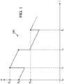
- the output value of a pressure sensor is represented by the curve 100.
- this pressure sensor is designed to detect if a user is on a bed (state: presence of the user or "high” state) or not on the bed (state: non-presence of the user or "low” state). Even if this example has only two different states, it is possible to generalize this example to any number of states (e.g. a motion sensor which has three states: one state for "no movement", one state for "walking", one state for "running”).
- the output value of the pressure may be p 0 which is, at that time t 0 , associated with the low state.
- the output value of the sensor may decrease (due for instance to leaks).
- time t 1 it is apparent, due to the sudden change of the output value up to p 1 , that a person is present in the bed (high state).
- the output value of the sensor may decrease (same reason(s) as above).
- time t 2 it is apparent, due to the sudden change of the output, that the person has left (low state).
- the output value of the sensor may decrease (same reason(s) as above).
- time t 3 it is apparent, due to the sudden change of the output value up to p 3 , that a person is present in the bed (high state). Nevertheless, it is noted that p 3 is less than p 0 . Therefore, if the value of p 0 is used as a reference of the low state, it may induce incorrect detections / determination of the state.
- the drifting of the sensor is determined by computing a running average or sliding window average of the value of the sensor. This process assumes that, most of the time, the sensor detects a "normal state": this is the reason a simple average may provide a satisfactory result in this specific situation. Nevertheless, if a plurality of states may be detected with important probabilities (e.g. three states may be detected with a respective probability rating of 30%, 30% and 40%), it is not possible to perform a simple mean.
- the memory of the device which should perform such determination could be limited. Therefore, the process used may limit the memory used for said determination.
- a method of associating at least one state in a plurality of states to a new value output by a drifting sensor comprising:
- the received signal may be a part of a more global signal.
- the received signal may be the last x seconds of a longer signal (sliding window).
- the distance of step /c/ may be a mathematical difference (absolute value) of the new value and the barycenter value of each cluster.
- the signal may be compressed into a compressed signal having values, the values of the compressed signal being used as the values of the signal in step /b/.
- the compressing may be an approximation of said signal by a piecewise constant function or staircase function.
- the compressing may also comprise:
- the first value of the signal may be a value output by the sensor before all second values.
- step /e/ for each second value in the order of the output by the sensor.
- Test /e1/ creates a new compressed value for the signal if the new value is "too" different from the previously computed compressed value (i.e. the average value), for example if it differs by more than a threshold amount.
- Test /e2/ updates the previously computed compressed value (i.e. the average value) if the previous tests are not matched. This updating may take into account the average value weighted by the number of second points used (e.g. /e/ is executed N times since the last storage, then this number would be N) and the new value. These last two values may be added and divided by N+1.
- another test may be executed: /e3/ if a number of second values used to determine the average value is greater than a predetermined threshold, setting the average value to the second value.
- test /e2/ is executed only both tests /e1/ and /e3/ fail.
- Test /e3/ creates a new compressed value for the signal if no important change in the signal (i.e. greater than the predetermined threshold) has been detected since a predetermined period of time (i.e. a predetermined number of second points). This new creation is motivated by the fact that, if a too great number is used to compute the average value, this average value may be non-representative of the signal.
- storage of the average value into a memory may be performed prior to setting the average value to the second value.
- the compressed value of the signal may be stored. If no storage is performed (which is also possible), it is equivalent to set the value of the compressed signal to the new average value for the period of time extending from the last storage to the current second point.
- the average value may be stored along a number of second values used for the determination of the average value after a previous storage of the average value.
- the storage of the number of second values used for the determination of the average value may be useful for weighting the clustering or for weighting the values of the cluster in the determination of its barycenter.
- each of the second value may be associated with a respective time/timestamp, and in step /e/, the average value may be stored along a minimum time among all the times associated with a second value used for the determination of the average value after a previous storage of the average value.
- step /b/ may comprise the use of a k-means algorithm or the use of an unsupervised clustering algorithm.
- the clustering of step /b/ may also comprises a weighting of the values of the signal by a number of second values used for the determination of the average value after a previous storage of the average value.
- Step /c/ may comprise the use of a forward algorithm (see “ An Efficient Forward-Backward Algorithm for an Explicit-Duration Hidden Markov Model” by Yu and Kobayashi, IEEE Signal Processing Letters, Vol. 10, No. 1, January 2003 )or the use of a decision tree (see “ Classification and Regression Trees” by Leland Wilkinson, University of Illinois at Urbana-Champaign, August 2013 (retrievable as of 25 May 2016 at http://cda.psych.uiuc.edu/multivariate_fall_2013/systat_cart_manual.pdf )).
- a second aspect relates to an apparatus comprising: a processor; and a memory including computer program code, the memory and the computer program code configured to, with the processor, cause the apparatus at least to perform: associating at least one state in a plurality of states to a new value output by a drifting sensor, comprising:
- a third aspect relates to a computer program product comprising a computer readable medium, having thereon a computer program comprising program instructions.
- the computer program is loadable into a data-processing unit and adapted to cause the data-processing unit to carry out the method described above when the computer program is run by the data-processing unit.
- an apparatus comprising means for performing any of the above described method steps.
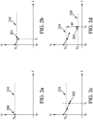
- Figure 2 is an example of "compression" of a signal into a piecewise function in a possible embodiment of the invention.
- a signal output by a sensor is often a high frequency sampled set of values.
- said of values may be derived from a continuous signal after a sampling of 5 Hz to 50 Hz or may be generated by measurements made by the sensor at 5 Hz to 50 Hz.
- a number of point N points is initialized to 1 and a starting time t start is set to t 0 ,
- the set of the average value V , the starting time t start and the number of points N points may be stored in a memory to represent the compressed signal.
- the average value V may be unset (or set to " undefined ”) .
- the set of the average value V , the starting time t start and the number of points N points may be stored in a memory to represent the compressed signal.
- the average value V may be unset (or set to " undefined ") .
- the value V 203 is thus processed as the value V 200 in figure 2(a) and a new average value V is created (220) equal to V 203 .
- the "compressed" signal comprises a number of “pieces” of piecewise signal, each piece being defined by a start (e.g. a starting time t start ), a length (e.g. a number of points N points ) and a value (e.g. an average value V ).
- the pseudo-code for this compressing may be:
- pseudo code may be also:
- nb_value has been split into two variables i.e. nb_value1 and nb_value2.
- nb_value1 represents the number of values used since the last storing of the average value
- nb_value2 represents the number of values used since the resetting of the average value. This splitting increases the impact of a new value on the average value.
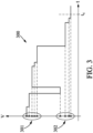
- Figure 3 is an example of "clustering" of a signal in a possible embodiment of the invention.
- Cluster analysis or “clustering” is the task of grouping a set of objects (here the values of the signal) in such a way that objects in the same group (called a cluster) are “closer” to each other than to those in other groups (clusters).
- the number of clusters may be set to any number greater or equal to 2.
- “Closer” may be understood as “closer according to a given mathematical distance”. Any mathematical distance may be used.
- This clustering is possible on the raw signal (i.e. the high frequency sampled signal) but it is advantageous to perform this clustering on a compressed signal (for instance, based on the method described in Figure 2 ) as the memory and the processing means of the device may be limited.
- a clustering algorithm may be applied to the values of the signal without weighting.
- a clustering algorithm may be applied to the values of the compressed signal (i.e. V according to Figure 2 ) with a weighting (i.e. each current point may be weighted by the length / the number of points N points associated with the current point).
- clustering algorithm such as an unsupervised clustering algorithm (e.g. k-means algorithm, see “ Algorithm AS 136: A K-Means Clustering Algorithm” by Hartigan and Wong, Journal of the Royal Statistical Society. Series C (Applied Statistics), Vol. 28, No. 1(1979), pp. 100-108, published by Blackwell Publishing ).
- unsupervised clustering algorithm e.g. k-means algorithm, see " Algorithm AS 136: A K-Means Clustering Algorithm” by Hartigan and Wong, Journal of the Royal Statistical Society. Series C (Applied Statistics), Vol. 28, No. 1(1979), pp. 100-108, published by Blackwell Publishing ).
- a clustering algorithm may determine that the values of signal 300 may be split into two clusters 301 and 302.
- clustering algorithm that supports update mechanisms: when the clusters are determined and when a new value is received in the signal at a time t c , the cluster may be easily updated without re-computing the whole clusters.
- this point may be associated with the closest cluster (e.g. the cluster whose barycenter is the closest).
- Figure 4 is an example of a determination of a cluster associated with a new event in the signal in a possible embodiment of the invention.
- the distance d H of said point 403 to C H (line 401) is determined and the distance d L of said point 403 to C L (line 402) is determined.
- a value representing the probability the new value 403 represents an event of the first cluster e.g. the user is present in the bed in the case the sensor is detecting a pressure in the bed
- This probability may be a binary probability (e.g. 0 or 1 only) or a "more complex" probability (e.g. a real value between 0 and 1).
- P H may also be function of the previous values of the signal.
- P H may be determined based on a learning process (e.g. with a neural network for instance). Therefore, a decision tree may be used to limit the use of memory during the determination of P H . Hysteresis thresholding or forward algorithm may also be used for such determination.
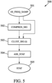
- Figure 5 is a flow chart describing a possible embodiment of the present invention. Part of this flow chart can represent steps of an example of a computer program which may be executed by an electronic device.
- a signal e.g. a high frequency sampled signal
- the reception of said signal may be in one "block” (i.e. receiving a single set of data containing the whole signal) but may also be “on the fly” (i.e. receiving the data as soon as it is generated by the sensor).
- the compression (step 502) is optional.
- the signal may be already compressed or it has been determined that the memory/processing means of the devices are not a limit for processing the data.
- step 503 two or more clusters based on the signal (step 503) as detailed in relation of Figure 3 .
- step 504 For each point of the signal (and especially the last received point if the signal is received on the fly), it is possible to determine a probability rating (step 504) as detailed in relation of Figure 4 .
- this probability rating (505) may be output.
- an indication to which state (i.e. cluster) the point is related may be output.
- Figure 6 is a possible embodiment for a device that enables the present invention.
- the device 600 comprise a computer, this computer comprising a memory 605 to store program instructions loadable into a circuit 604 and adapted to cause circuit 604 to carry out the steps of the present invention when the program instructions are run by the circuit 604.
- the memory 605 may also store data and useful information for carrying the steps of the present invention as described above.
- the circuit 604 may be for instance:
- This computer comprises an input interface 603 for the reception of the signal according to the invention and an output interface 606.
- a screen 601 and a keyboard 602 may be provided and connected to the computer circuit 604.
Landscapes
- Engineering & Computer Science (AREA)
- Physics & Mathematics (AREA)
- Theoretical Computer Science (AREA)
- General Physics & Mathematics (AREA)
- Mathematical Optimization (AREA)
- Pure & Applied Mathematics (AREA)
- Data Mining & Analysis (AREA)
- Evolutionary Computation (AREA)
- Artificial Intelligence (AREA)
- Mathematical Analysis (AREA)
- Algebra (AREA)
- Computational Mathematics (AREA)
- Computing Systems (AREA)
- General Engineering & Computer Science (AREA)
- Mathematical Physics (AREA)
- Software Systems (AREA)
- Probability & Statistics with Applications (AREA)
- Testing Or Calibration Of Command Recording Devices (AREA)
- Testing And Monitoring For Control Systems (AREA)
- Measurement Of The Respiration, Hearing Ability, Form, And Blood Characteristics Of Living Organisms (AREA)
Description
- The present invention relates to the domain of the sensors and especially to the domain of the use of a sensor while its value(s) may slightly drift.
- The approaches described in this section could be pursued, but are not necessarily approaches that have been previously conceived or pursued. Therefore, unless otherwise indicated herein, the approaches described in this section are not prior art to the claims in this application and are not admitted to be prior art by inclusion in this section. Furthermore, all embodiments are not necessarily intended to solve all or even any of the problems brought forward in this section.
- Document
US2003/202709 A1 discloses the compression of a digital document by extracting and clustering data from the document. - Document
US2011/222584 A1 teaches a drift of an electronic circuit used in an active transmitter of a communication system, resulting in a problem of drift to be compensated between the drifting transmitter and the coupled receiver of the communication system. DocumentWO 2013/049748 discloses relevant background art. - Normally, when using a sensor, the users may expect that the output value may be constant if the detected characteristics are constant / are identical. For instance, for a pressure sensor, if the pressure to be detected is constant at 2 bars, it may be expected that the output value of the sensor is constant (e.g. 128 for 2 bars, 64 for 1 bar, 32 for 0.5 bars, etc.).
- Nevertheless, this is not always the case.
- Due to some technologies used for some sensors, the output value may slightly drift: the output value (e.g. numerical) may be 128 for 2 bars at a time t0, between 115 and 120 for 2 bars at a time t0+2h, etc.
- Therefore, when it should be determined whether the output value represents a given state (e.g. a "high" value of the sensor may be associated with the state of the presence of a user on a pressure sensor, a "low" value of the sensor may be associated with the state of non-presence of a user on a pressure sensor) it may be difficult to determine in which state the sensor is.
- For instance, in the example of
Figure 1 , the output value of a pressure sensor is represented by thecurve 100. For instance, this pressure sensor is designed to detect if a user is on a bed (state: presence of the user or "high" state) or not on the bed (state: non-presence of the user or "low" state). Even if this example has only two different states, it is possible to generalize this example to any number of states (e.g. a motion sensor which has three states: one state for "no movement", one state for "walking", one state for "running"). - At t0, the output value of the pressure may be p0 which is, at that time t0, associated with the low state. Between time t0 and t1, the output value of the sensor may decrease (due for instance to leaks). At time t1, it is apparent, due to the sudden change of the output value up to p1, that a person is present in the bed (high state). One may detect that this is a "high state" as the pressure p1 is greater than p1. Between time t1 and t2, the output value of the sensor may decrease (same reason(s) as above). At time t2, it is apparent, due to the sudden change of the output, that the person has left (low state). Between time t2 and t3, the output value of the sensor may decrease (same reason(s) as above). At time t3, it is apparent, due to the sudden change of the output value up to p3, that a person is present in the bed (high state). Nevertheless, it is noted that p3 is less than p0. Therefore, if the value of p0 is used as a reference of the low state, it may induce incorrect detections / determination of the state.
- Thus, there is a need for accurately determining various states based on a sensor whose output value may drift in time, with possibility noisy conditions.
- If only one state (i.e. a normal state) may be determined, then the drifting of the sensor is determined by computing a running average or sliding window average of the value of the sensor. This process assumes that, most of the time, the sensor detects a "normal state": this is the reason a simple average may provide a satisfactory result in this specific situation. Nevertheless, if a plurality of states may be detected with important probabilities (e.g. three states may be detected with a respective probability rating of 30%, 30% and 40%), it is not possible to perform a simple mean.
- In addition, the memory of the device which should perform such determination could be limited. Therefore, the process used may limit the memory used for said determination.
- The invention is defined by the appended claims.
- In a first aspect there is provided a method of associating at least one state in a plurality of states to a new value output by a drifting sensor, the method comprising:
- /a/ receiving a signal from the sensor, said signal comprising a plurality of values;
- /b/ clustering the values of said signal into a number of clusters equal to the number of the plurality of states, each cluster being associated with a respective state in the plurality of states;
- /c/ for the new value of the signal, associating at least one state in said plurality of states or a probability rating representing the probability to be associated with one state in said plurality of states for said new value of the signal, the associated state or the associated probability rating being determined based on at least distances of said new value of the signal to respective clusters.
- The received signal may be a part of a more global signal.
- For instance, the received signal may be the last x seconds of a longer signal (sliding window).
- Thanks to this method, it is possible to set dynamically the values of the states of the signal (e.g. the person is sleeping, the person is walking, the person is running), even if the sensor outputting the signal is drifting.
- By clustering the signal, it is possible to avoid assuming any state of the signal before processing it (e.g. no need to associate to a new value a state so that an average value of the state is computed for this state).
- The distance of step /c/ may be a mathematical difference (absolute value) of the new value and the barycenter value of each cluster.
- In addition, prior to step /b/, the signal may be compressed into a compressed signal having values, the values of the compressed signal being used as the values of the signal in step /b/.
- The compressing may be an approximation of said signal by a piecewise constant function or staircase function.
- The compressing may also comprise:
- /d/ initializing an average value to a first value of the signal,
- /e/ for each second value in a plurality of second values of the signal output after the first value from the sensor:
- /e1/ if a distance between the second value and the average value is greater than a predetermined threshold, storing the average value as the compressed value into a memory and setting the average value to the second value,
- /e2/ otherwise, updating the average value to a new average value as a function of the second value and the average value.
- The first value of the signal may be a value output by the sensor before all second values.
- In addition, it may be usual to iterate step /e/ for each second value in the order of the output by the sensor.
- Test /e1/ creates a new compressed value for the signal if the new value is "too" different from the previously computed compressed value (i.e. the average value), for example if it differs by more than a threshold amount.
- Test /e2/ updates the previously computed compressed value (i.e. the average value) if the previous tests are not matched. This updating may take into account the average value weighted by the number of second points used (e.g. /e/ is executed N times since the last storage, then this number would be N) and the new value. These last two values may be added and divided by N+1.
- In the step /e/ and prior to the test /e2/, another test may be executed:
/e3/ if a number of second values used to determine the average value is greater than a predetermined threshold, setting the average value to the second value. - Therefore, the test /e2/ is executed only both tests /e1/ and /e3/ fail.
- Test /e3/ creates a new compressed value for the signal if no important change in the signal (i.e. greater than the predetermined threshold) has been detected since a predetermined period of time (i.e. a predetermined number of second points). This new creation is motivated by the fact that, if a too great number is used to compute the average value, this average value may be non-representative of the signal.
- In a specific embodiment, in test /e3/, storage of the average value into a memory may be performed prior to setting the average value to the second value.
- By storing the average value in step /e3/, the compressed value of the signal may be stored. If no storage is performed (which is also possible), it is equivalent to set the value of the compressed signal to the new average value for the period of time extending from the last storage to the current second point.
- In step /e/, the average value may be stored along a number of second values used for the determination of the average value after a previous storage of the average value.
- The storage of the number of second values used for the determination of the average value may be useful for weighting the clustering or for weighting the values of the cluster in the determination of its barycenter.
- In a given embodiment, each of the second value may be associated with a respective time/timestamp, and in step /e/, the average value may be stored along a minimum time among all the times associated with a second value used for the determination of the average value after a previous storage of the average value.
- In addition, the clustering of step /b/ may comprise the use of a k-means algorithm or the use of an unsupervised clustering algorithm.
- The clustering of step /b/ may also comprises a weighting of the values of the signal by a number of second values used for the determination of the average value after a previous storage of the average value.
- Step /c/ may comprise the use of a forward algorithm (see "An Efficient Forward-Backward Algorithm for an Explicit-Duration Hidden Markov Model" by Yu and Kobayashi, IEEE Signal Processing Letters, Vol. 10, No. 1, January 2003)or the use of a decision tree (see "Classification and Regression Trees" by Leland Wilkinson, University of Illinois at Urbana-Champaign, August 2013 (retrievable as of 25 May 2016 at http://cda.psych.uiuc.edu/multivariate_fall_2013/systat_cart_manual.pdf)).
- A second aspect relates to an apparatus comprising:
a processor; and a memory including computer program code, the memory and the computer program code configured to, with the processor, cause the apparatus at least to perform: associating at least one state in a plurality of states to a new value output by a drifting sensor, comprising: - /a/ receiving a signal from the sensor, said signal comprising a plurality of values;
- /b/ clustering the values of said signal into a number of clusters equal to the number of the plurality of states, each cluster being associated with a respective state in the plurality of states;
- /c/ for the new value of the signal, associating at least one state in said plurality of states or a probability rating representing the probability to be associated with one state in said plurality of states for said new value of the signal, the associated state or the associated probability rating being determined based on at least distances of said new value of the signal to respective clusters.
- A third aspect relates to a computer program product comprising a computer readable medium, having thereon a computer program comprising program instructions. The computer program is loadable into a data-processing unit and adapted to cause the data-processing unit to carry out the method described above when the computer program is run by the data-processing unit.
- Other features and advantages of the method and apparatus disclosed herein will become apparent from the following description of non-limiting embodiments, with reference to the appended drawings.
- According to a further aspect, there is provided an apparatus comprising means for performing any of the above described method steps.
- The present invention is illustrated by way of example, and not by way of limitations, in the figures of the accompanying drawings, in which like reference numerals refer to similar elements and in which:
-
Figure 1 is an example of a drifting output value of a sensor; -
Figure 2 is an example of "compression" of a signal into a piecewise function in a possible embodiment of the invention; -
Figure 3 is an example of "clustering" of a signal in a possible embodiment of the invention; -
Figure 4 is an example of a determination of a cluster associated with a new event in the signal in a possible embodiment of the invention; -
Figure 5 is a flow chart describing a possible embodiment of the present invention; -
Figure 6 is a possible embodiment for a device. -
Figure 2 is an example of "compression" of a signal into a piecewise function in a possible embodiment of the invention. - A signal output by a sensor is often a high frequency sampled set of values. For instance, said of values may be derived from a continuous signal after a sampling of 5 Hz to 50 Hz or may be generated by measurements made by the sensor at 5 Hz to 50 Hz.
- Most of the time for small electronic devices (e.g. home connected devices), the whole signal cannot be stored in a memory and the manipulation of said signal may be difficult.
- In order to avoid storing unneeded information, the following process may be executed.
- Upon receiving a new value V 200 (
Figure 2(a) , 200) of the signal at time t0, it is determined if an average value 210 (namelyV ) is defined. - If not, the average value is initialized: the average value
V is then defined to a value equal to the new value V 200 of the signal (Figure 2(a) ) i.e.V = V 0 = V 200. - In addition, a number of point Npoints is initialized to 1 and a starting time tstart is set to t 0,
- Upon receiving a new value V 201 (
Figure 2(b) , 201) of the signal at time t 1, and if the average valueV is defined/initialized, said average valueV is updated to a new value V 1 which is a function of the old average valueV and the new value V 201. For instance, it is possible to compute:
- In addition, it is possible to update the number of points:

- Upon receiving a new value V 202 (
Figure 2(c) , 202) of the signal at time t2, the same process described in relation ofFigure 2(b) is executed: as the average valueV is defined, said average valueV is updated to a new value V 2 that is a function of the old average valueV and the new value V 202. For instance, it is possible to compute:
- In addition, it is possible to update the number of points:

- Nevertheless, it is possible to add further conditions for the updating of the average value
V . - For instance, if the number of points Npoints is greater than a predetermined threshold, the set of the average value
V , the starting time tstart and the number of points Npoints may be stored in a memory to represent the compressed signal. - Then, the average value
V may be unset (or set to "undefined"). - To further compress the signal, it is also possible to skip the storing step (for this condition) and only set the average value
V to the next received value of the signal / the last received value of the signal without unsetting the average valueV : by doing so, the starting time tstart and the number of points N points are kept without being reset. It is equivalent to setting all the previous "pieces" of the compressed piecewise signal to the new current average valueV (e.g. searching all the consecutive and previous storage in the memory where the difference between the stored average value and the current average value is below a predetermined threshold and reset all the found stored average value to the current average value). - Alternatively or in addition, if a distance between the new value V 203 (
Figure 2(d) , 203) of the signal at time t 3 and the average valueV is greater than a predefined threshold (e.g. if ΔV = |V 203 -V| is greater than a predefined threshold), the set of the average valueV , the starting time tstart and the number of points Npoints may be stored in a memory to represent the compressed signal. - Then, the average value
V may be unset (or set to "undefined"). The value V 203 is thus processed as the value V 200 infigure 2(a) and a new average valueV is created (220) equal to V 203. - Therefore, the "compressed" signal comprises a number of "pieces" of piecewise signal, each piece being defined by a start (e.g. a starting time tstart ), a length (e.g. a number of points Npoints ) and a value (e.g. an average value
V ). - The pseudo-code for this compressing may be:


- Alternatively, the pseudo code may be also:


- In the latter pseudo code, the variable nb_value has been split into two variables i.e. nb_value1 and nb_value2. Indeed, nb_value1 represents the number of values used since the last storing of the average value while nb_value2 represents the number of values used since the resetting of the average value. This splitting increases the impact of a new value on the average value.
-
Figure 3 is an example of "clustering" of a signal in a possible embodiment of the invention. - "Cluster analysis" or "clustering" is the task of grouping a set of objects (here the values of the signal) in such a way that objects in the same group (called a cluster) are "closer" to each other than to those in other groups (clusters). The number of clusters may be set to any number greater or equal to 2. "Closer" may be understood as "closer according to a given mathematical distance". Any mathematical distance may be used.
- This clustering is possible on the raw signal (i.e. the high frequency sampled signal) but it is advantageous to perform this clustering on a compressed signal (for instance, based on the method described in
Figure 2 ) as the memory and the processing means of the device may be limited. - If the signal is not compressed (i.e. the signal is sampled at a given/constant frequency), a clustering algorithm may be applied to the values of the signal without weighting.
- If the signal is compressed, a clustering algorithm may be applied to the values of the compressed signal (i.e.
V according toFigure 2 ) with a weighting (i.e. each current point may be weighted by the length / the number of points Npoints associated with the current point). - Many clustering algorithm may be used such as an unsupervised clustering algorithm (e.g. k-means algorithm, see "Algorithm AS 136: A K-Means Clustering Algorithm" by Hartigan and Wong, Journal of the Royal Statistical Society. Series C (Applied Statistics), Vol. 28, No. 1(1979), pp. 100-108, published by Blackwell Publishing).
- For instance, if two clusters are searched, a clustering algorithm may determine that the values of
signal 300 may be split into twoclusters - It is advantageous to use a clustering algorithm that supports update mechanisms: when the clusters are determined and when a new value is received in the signal at a time tc , the cluster may be easily updated without re-computing the whole clusters.
- For instance, when a point of the signal is newly received, this point may be associated with the closest cluster (e.g. the cluster whose barycenter is the closest).
-
Figure 4 is an example of a determination of a cluster associated with a new event in the signal in a possible embodiment of the invention. - In said example, it is assumed that two clusters have been previously determined and that CH is a barycenter of one of the clusters and that CL is a barycenter of the other cluster.
- Upon the reception of a
new point 403 of thesignal 400 at a time tc , the distance dH of saidpoint 403 to CH (line 401) is determined and the distance dL of saidpoint 403 to CL (line 402) is determined. - Based on said determined distances (and possible other parameters), it is possible to compute a value representing the probability the
new value 403 represents an event of the first cluster (e.g. the user is present in the bed in the case the sensor is detecting a pressure in the bed) or of the second cluster (e.g. the user is not present in the bed in the case the sensor is detecting a pressure in the bed). This probability may be a binary probability (e.g. 0 or 1 only) or a "more complex" probability (e.g. a real value between 0 and 1). - For instance, the probability PH that the
new value 403 represents an event of the first cluster (whose barycenter is CH ) may be:

- PH may also be function of the previous values of the signal.
- In addition, PH may be determined based on a learning process (e.g. with a neural network for instance). Therefore, a decision tree may be used to limit the use of memory during the determination of PH. Hysteresis thresholding or forward algorithm may also be used for such determination.
-
Figure 5 is a flow chart describing a possible embodiment of the present invention. Part of this flow chart can represent steps of an example of a computer program which may be executed by an electronic device. - Upon receiving 501 a signal (e.g. a high frequency sampled signal), it is possible to compress it (step 502) as detailed in relation of
Figure 2 . The reception of said signal may be in one "block" (i.e. receiving a single set of data containing the whole signal) but may also be "on the fly" (i.e. receiving the data as soon as it is generated by the sensor). - The compression (step 502) is optional. The signal may be already compressed or it has been determined that the memory/processing means of the devices are not a limit for processing the data.
- It is thus possible to compute (step 503) two or more clusters based on the signal (step 503) as detailed in relation of
Figure 3 . - For each point of the signal (and especially the last received point if the signal is received on the fly), it is possible to determine a probability rating (step 504) as detailed in relation of
Figure 4 . - Finally, this probability rating (505) may be output. Alternatively or in parallel, an indication to which state (i.e. cluster) the point is related may be output.
-
Figure 6 is a possible embodiment for a device that enables the present invention. - In this embodiment, the
device 600 comprise a computer, this computer comprising amemory 605 to store program instructions loadable into acircuit 604 and adapted to causecircuit 604 to carry out the steps of the present invention when the program instructions are run by thecircuit 604. - The
memory 605 may also store data and useful information for carrying the steps of the present invention as described above. - The
circuit 604 may be for instance: - a processor or a processing unit adapted to interpret instructions in a computer language, the processor or the processing unit may comprise, may be associated with or be attached to a memory comprising the instructions, or
- the association of a processor / processing unit and a memory, the processor or the processing unit adapted to interpret instructions in a computer language, the memory comprising said instructions, or
- an electronic card wherein the steps of the invention are described within silicon, or
- a programmable electronic chip such as a FPGA chip (for « Field-Programmable Gate Array »).
- This computer comprises an
input interface 603 for the reception of the signal according to the invention and anoutput interface 606. - To ease the interaction with the computer, a
screen 601 and akeyboard 602 may be provided and connected to thecomputer circuit 604. - Expressions such as "comprise", "include", "incorporate", "contain", "is" and "have" are to be construed in a non-exclusive manner when interpreting the description and its associated claims, namely construed to allow for other items or components which are not explicitly defined also to be present. Reference to the singular is also to be construed in being a reference to the plural and vice versa.
- A person skilled in the art will readily appreciate that various parameters disclosed in the description may be modified and that various embodiments disclosed may be combined without departing from the scope of the invention.
Claims (13)
- A method of detecting the presence of a user in a bed by associating at least one state in a plurality of states to a new value output by a drifting pressure sensor, the plurality of states comprising a state associated to the user being present in the bed and a state associated to the user being not present in the bed, the method comprising:/a/ receiving a signal (501) from the drifting pressure sensor, said signal comprising a plurality of values (200, 201, 202, 203);/b/ clustering (503) the plurality of values of said signal into a number of clusters (301, 302) equal to the number of the plurality of states, each cluster being associated with a respective state in the plurality of states;/c/ for the new value of the signal, associating (504) at least one state in said plurality of states or a probability rating representing a probability to be associated with one state in said plurality of states for said new value of the signal, the associated state or the associated probability rating being determined based on at least distances (dH, dL) of said new value of the signal to respective clusters, each distance (dH, dL) being a mathematical difference in absolute value between the new value and barycenter values of the clusters (301, 302),wherein, prior to step /b/, the signal is compressed (502) into a compressed signal having compressed values, the compressed values of the compressed signal being used as the plurality of values of the signal in step /b/,wherein said compressing comprises:/d/ initializing an average value (210) to a first value (200) of the signal,/e/ for each second value in a plurality of second values (201, 202, 203) of the signal output after the first value from the drifting sensor:
/e1/ if a distance (ΔV) between the second value and the average value is greater than a predetermined threshold, storing the average value as a compressed value into a memory and setting the average value to the second value,/e2/ otherwise, updating the average value to a new average value as a function of the second value and the average value. - A method of detecting the motion of a user by associating at least one state in a plurality of states to a new value output by a drifting motion sensor, the plurality of states comprising a state associated to the user not moving, a state associated to the user walking and a state associated to the user running, the method comprising:/a/ receiving a signal (501) from the drifting motion sensor, said signal comprising a plurality of values (200, 201, 202, 203);/b/ clustering (503) the plurality of values of said signal into a number of clusters (301, 302) equal to the number of the plurality of states, each cluster being associated with a respective state in the plurality of states;/c/ for the new value of the signal, associating (504) at least one state in said plurality of states or a probability rating representing a probability to be associated with one state in said plurality of states for said new value of the signal, the associated state or the associated probability rating being determined based on at least distances (dH, dL) of said new value of the signal to respective clusters, each distance (dH, dL) being a mathematical difference in absolute value between the new value and barycenter values of the clusters (301, 302),wherein, prior to step /b/, the signal is compressed (502) into a compressed signal having compressed values, the compressed values of the compressed signal being used as the plurality of values of the signal in step /b/,wherein said compressing comprises:/d/ initializing an average value (210) to a first value (200) of the signal,/e/ for each second value in a plurality of second values (201, 202, 203) of the signal output after the first value from the drifting sensor:
/e1/ if a distance (ΔV) between the second value and the average value is greater than a predetermined threshold, storing the average value as a compressed value into a memory and setting the average value to the second value,/e2/ otherwise, updating the average value to a new average value as a function of the second value and the average value. - The method according to claim 1 or 2, wherein, in the step /e/ and prior to the test /e2/, another test is executed:
/e3/ if a number of second values used to determine the average value is greater than a predetermined threshold, setting the average value to the second value. - The method according to claim 3, wherein, in test /e3/, storage of the average value into a memory is performed prior to setting the average value to the second value.
- The method according to claim 1 or 2, wherein, in step /e/, the average value is stored along a number of second values used for the determination of the average value after a previous storage of the average value.
- The method according to claim 1 or 2, wherein each second value is associated with a respective time, and
wherein in step /e/, the average value is stored along a minimum time among all the times associated with a second value used for the determination of the average value after a previous storage of the average value. - The method according to any preceding claim, wherein the clustering of step /b/ comprises the use of a k-means algorithm or the use of an unsupervised clustering algorithm.
- The method according to claim 1 or 2, wherein the clustering of step /b/ comprises a weighting of the plurality of values of the signal by a number of second values used for the determination of the average value after a previous storage of the average value.
- The method according to any preceding claim, wherein step /c/ comprises the use of a forward algorithm and/or a decision tree.
- The method according to any preceding claim, wherein the clustering algorithm supports update mechanisms.
- The method according to any preceding claim, wherein the received signal is comprised in a sliding time-window.
- A non-transitory computer readable storage medium, having stored thereon a computer program comprising program instructions, the computer program being loadable into a data-processing unit and adapted to cause the data-processing unit to carry out, when the computer program is run by the data-processing device, a method according to any of the preceding claims.
- An apparatus comprising means for performing the method of any of claims 1 to 11.
Applications Claiming Priority (2)
| Application Number | Priority Date | Filing Date | Title |
|---|---|---|---|
| US15/164,329 US10748073B2 (en) | 2016-05-25 | 2016-05-25 | Method and device for associating a state to a new value output by a drifting sensor |
| PCT/EP2017/062442 WO2017202856A1 (en) | 2016-05-25 | 2017-05-23 | Method and device for associating a state to a new value output by a drifting sensor |
Publications (2)
| Publication Number | Publication Date |
|---|---|
| EP3465918A1 EP3465918A1 (en) | 2019-04-10 |
| EP3465918B1 true EP3465918B1 (en) | 2024-11-06 |
Family
ID=59070600
Family Applications (1)
| Application Number | Title | Priority Date | Filing Date |
|---|---|---|---|
| EP17730683.4A Active EP3465918B1 (en) | 2016-05-25 | 2017-05-23 | Method and device for associating a state to a new value output by a drifting sensor |
Country Status (3)
| Country | Link |
|---|---|
| US (1) | US10748073B2 (en) |
| EP (1) | EP3465918B1 (en) |
| WO (1) | WO2017202856A1 (en) |
Citations (6)
| Publication number | Priority date | Publication date | Assignee | Title |
|---|---|---|---|---|
| EP1065097A1 (en) * | 1999-01-27 | 2001-01-03 | The Furukawa Electric Co., Ltd. | Occupant detecting device |
| US20030202709A1 (en) * | 2002-04-25 | 2003-10-30 | Simard Patrice Y. | Clustering |
| US20110222584A1 (en) * | 2010-03-11 | 2011-09-15 | Harris Corporation | Hidden markov model detection for spread spectrum waveforms |
| US20110264691A1 (en) * | 2010-04-26 | 2011-10-27 | Migita Takahito | Information processing apparatus, text selection method, and program |
| WO2013049748A2 (en) * | 2011-09-30 | 2013-04-04 | Newcare Solutions, Llc. | Sensors and monitoring systems comprising sensors |
| WO2016061668A1 (en) * | 2014-10-23 | 2016-04-28 | 2352409 Ontario Inc. | Device and method for identifying subject's activity profile |
Family Cites Families (8)
| Publication number | Priority date | Publication date | Assignee | Title |
|---|---|---|---|---|
| US4926674A (en) * | 1988-11-03 | 1990-05-22 | Innovex Inc. | Self-zeroing pressure signal generator |
| FR2683313B1 (en) * | 1991-10-30 | 1995-12-08 | Labinal | DEVICE FOR MEASURING PARAMETERS, ESPECIALLY PARAMETERS RELATING TO AIRCRAFT OR VEHICLE WHEELS. |
| JP3682039B2 (en) * | 2002-10-02 | 2005-08-10 | 株式会社デンソー | Vehicle occupant detection device |
| US8838513B2 (en) * | 2011-03-24 | 2014-09-16 | WellDoc, Inc. | Adaptive analytical behavioral and health assistant system and related method of use |
| EP2017139A1 (en) * | 2007-07-17 | 2009-01-21 | IEE International Electronics & Engineering S.A.R.L. | Occupant detection system for an automotive vehicle |
| US8219574B2 (en) * | 2009-06-22 | 2012-07-10 | Microsoft Corporation | Querying compressed time-series signals |
| US20120253233A1 (en) * | 2011-03-31 | 2012-10-04 | Greene Barry | Algorithm for quantitative standing balance assessment |
| US20170167939A1 (en) * | 2015-12-15 | 2017-06-15 | Honeywell International, Inc. | Pressure sensor drift detection and correction |
-
2016
- 2016-05-25 US US15/164,329 patent/US10748073B2/en active Active
-
2017
- 2017-05-23 EP EP17730683.4A patent/EP3465918B1/en active Active
- 2017-05-23 WO PCT/EP2017/062442 patent/WO2017202856A1/en not_active Ceased
Patent Citations (6)
| Publication number | Priority date | Publication date | Assignee | Title |
|---|---|---|---|---|
| EP1065097A1 (en) * | 1999-01-27 | 2001-01-03 | The Furukawa Electric Co., Ltd. | Occupant detecting device |
| US20030202709A1 (en) * | 2002-04-25 | 2003-10-30 | Simard Patrice Y. | Clustering |
| US20110222584A1 (en) * | 2010-03-11 | 2011-09-15 | Harris Corporation | Hidden markov model detection for spread spectrum waveforms |
| US20110264691A1 (en) * | 2010-04-26 | 2011-10-27 | Migita Takahito | Information processing apparatus, text selection method, and program |
| WO2013049748A2 (en) * | 2011-09-30 | 2013-04-04 | Newcare Solutions, Llc. | Sensors and monitoring systems comprising sensors |
| WO2016061668A1 (en) * | 2014-10-23 | 2016-04-28 | 2352409 Ontario Inc. | Device and method for identifying subject's activity profile |
Also Published As
| Publication number | Publication date |
|---|---|
| EP3465918A1 (en) | 2019-04-10 |
| US20170344894A1 (en) | 2017-11-30 |
| US10748073B2 (en) | 2020-08-18 |
| WO2017202856A1 (en) | 2017-11-30 |
Similar Documents
| Publication | Publication Date | Title |
|---|---|---|
| US11636341B2 (en) | Processing sequential interaction data | |
| US20230316720A1 (en) | Anomaly detection apparatus, anomaly detection method, and program | |
| US20200387798A1 (en) | Time invariant classification | |
| US10783452B2 (en) | Learning apparatus and method for learning a model corresponding to a function changing in time series | |
| KR20210017342A (en) | Time series prediction method and apparatus based on past prediction data | |
| EP4131076A1 (en) | Serialized data processing method and device, and text processing method and device | |
| KR101593315B1 (en) | Method, apparatus and computer program product for activity recognition | |
| Haynes et al. | Efficient penalty search for multiple changepoint problems | |
| US11100388B2 (en) | Learning apparatus and method for learning a model corresponding to real number time-series input data | |
| US20180232342A1 (en) | Text preparation apparatus | |
| CN112166390A (en) | Abnormality detection device, abnormality detection method, abnormality detection program, and recording medium | |
| KR20180024660A (en) | Machine learning system and method for learning user controlling pattern thereof | |
| CN113038386A (en) | Learning model based device positioning | |
| CN116482524B (en) | Power transmission and distribution switch state detection method and system | |
| JP4265296B2 (en) | Change point detection apparatus, change point detection method, and change point detection program | |
| US8938389B2 (en) | Voice activity detector, voice activity detection program, and parameter adjusting method | |
| Vořechovský | Reliability analysis of discrete-state performance functions via adaptive sequential sampling with detection of failure surfaces | |
| CN112462261A (en) | Motor abnormality detection method and device, electronic equipment and storage medium | |
| CN114817363A (en) | Method and device for determining data similarity, electronic equipment and storage medium | |
| US10782791B2 (en) | Time domain feature transform for user gestures | |
| US20250272545A1 (en) | Time-series dimension compression | |
| Alshareef et al. | A case-based reasoning approach for pattern detection in Malaysia rainfall data | |
| US10748073B2 (en) | Method and device for associating a state to a new value output by a drifting sensor | |
| EP4492292A1 (en) | Machine learning model domain adaptation for time-series data | |
| US20260017928A1 (en) | Learning device, learning method, and learning program |
Legal Events
| Date | Code | Title | Description |
|---|---|---|---|
| STAA | Information on the status of an ep patent application or granted ep patent |
Free format text: STATUS: UNKNOWN |
|
| STAA | Information on the status of an ep patent application or granted ep patent |
Free format text: STATUS: THE INTERNATIONAL PUBLICATION HAS BEEN MADE |
|
| PUAI | Public reference made under article 153(3) epc to a published international application that has entered the european phase |
Free format text: ORIGINAL CODE: 0009012 |
|
| STAA | Information on the status of an ep patent application or granted ep patent |
Free format text: STATUS: REQUEST FOR EXAMINATION WAS MADE |
|
| 17P | Request for examination filed |
Effective date: 20181220 |
|
| AK | Designated contracting states |
Kind code of ref document: A1 Designated state(s): AL AT BE BG CH CY CZ DE DK EE ES FI FR GB GR HR HU IE IS IT LI LT LU LV MC MK MT NL NO PL PT RO RS SE SI SK SM TR |
|
| AX | Request for extension of the european patent |
Extension state: BA ME |
|
| RIN1 | Information on inventor provided before grant (corrected) |
Inventor name: YANG, RUI-YI Inventor name: EDOUARD, PAUL Inventor name: HUTCHINGS, CEDRIC |
|
| DAV | Request for validation of the european patent (deleted) | ||
| DAX | Request for extension of the european patent (deleted) | ||
| STAA | Information on the status of an ep patent application or granted ep patent |
Free format text: STATUS: EXAMINATION IS IN PROGRESS |
|
| 17Q | First examination report despatched |
Effective date: 20201109 |
|
| GRAP | Despatch of communication of intention to grant a patent |
Free format text: ORIGINAL CODE: EPIDOSNIGR1 |
|
| STAA | Information on the status of an ep patent application or granted ep patent |
Free format text: STATUS: GRANT OF PATENT IS INTENDED |
|
| GRAS | Grant fee paid |
Free format text: ORIGINAL CODE: EPIDOSNIGR3 |
|
| GRAA | (expected) grant |
Free format text: ORIGINAL CODE: 0009210 |
|
| STAA | Information on the status of an ep patent application or granted ep patent |
Free format text: STATUS: THE PATENT HAS BEEN GRANTED |
|
| INTG | Intention to grant announced |
Effective date: 20240916 |
|
| AK | Designated contracting states |
Kind code of ref document: B1 Designated state(s): AL AT BE BG CH CY CZ DE DK EE ES FI FR GB GR HR HU IE IS IT LI LT LU LV MC MK MT NL NO PL PT RO RS SE SI SK SM TR |
|
| REG | Reference to a national code |
Ref country code: GB Ref legal event code: FG4D |
|
| REG | Reference to a national code |
Ref country code: CH Ref legal event code: EP |
|
| REG | Reference to a national code |
Ref country code: DE Ref legal event code: R096 Ref document number: 602017085916 Country of ref document: DE |
|
| REG | Reference to a national code |
Ref country code: IE Ref legal event code: FG4D |
|
| REG | Reference to a national code |
Ref country code: LT Ref legal event code: MG9D |
|
| REG | Reference to a national code |
Ref country code: NL Ref legal event code: MP Effective date: 20241106 |
|
| PG25 | Lapsed in a contracting state [announced via postgrant information from national office to epo] |
Ref country code: PT Free format text: LAPSE BECAUSE OF FAILURE TO SUBMIT A TRANSLATION OF THE DESCRIPTION OR TO PAY THE FEE WITHIN THE PRESCRIBED TIME-LIMIT Effective date: 20250306 Ref country code: IS Free format text: LAPSE BECAUSE OF FAILURE TO SUBMIT A TRANSLATION OF THE DESCRIPTION OR TO PAY THE FEE WITHIN THE PRESCRIBED TIME-LIMIT Effective date: 20250306 Ref country code: HR Free format text: LAPSE BECAUSE OF FAILURE TO SUBMIT A TRANSLATION OF THE DESCRIPTION OR TO PAY THE FEE WITHIN THE PRESCRIBED TIME-LIMIT Effective date: 20241106 |
|
| PG25 | Lapsed in a contracting state [announced via postgrant information from national office to epo] |
Ref country code: FI Free format text: LAPSE BECAUSE OF FAILURE TO SUBMIT A TRANSLATION OF THE DESCRIPTION OR TO PAY THE FEE WITHIN THE PRESCRIBED TIME-LIMIT Effective date: 20241106 Ref country code: NL Free format text: LAPSE BECAUSE OF FAILURE TO SUBMIT A TRANSLATION OF THE DESCRIPTION OR TO PAY THE FEE WITHIN THE PRESCRIBED TIME-LIMIT Effective date: 20241106 |
|
| REG | Reference to a national code |
Ref country code: AT Ref legal event code: MK05 Ref document number: 1740510 Country of ref document: AT Kind code of ref document: T Effective date: 20241106 |
|
| PG25 | Lapsed in a contracting state [announced via postgrant information from national office to epo] |
Ref country code: BG Free format text: LAPSE BECAUSE OF FAILURE TO SUBMIT A TRANSLATION OF THE DESCRIPTION OR TO PAY THE FEE WITHIN THE PRESCRIBED TIME-LIMIT Effective date: 20241106 |
|
| PG25 | Lapsed in a contracting state [announced via postgrant information from national office to epo] |
Ref country code: ES Free format text: LAPSE BECAUSE OF FAILURE TO SUBMIT A TRANSLATION OF THE DESCRIPTION OR TO PAY THE FEE WITHIN THE PRESCRIBED TIME-LIMIT Effective date: 20241106 |
|
| PG25 | Lapsed in a contracting state [announced via postgrant information from national office to epo] |
Ref country code: NO Free format text: LAPSE BECAUSE OF FAILURE TO SUBMIT A TRANSLATION OF THE DESCRIPTION OR TO PAY THE FEE WITHIN THE PRESCRIBED TIME-LIMIT Effective date: 20250206 |
|
| PG25 | Lapsed in a contracting state [announced via postgrant information from national office to epo] |
Ref country code: AT Free format text: LAPSE BECAUSE OF FAILURE TO SUBMIT A TRANSLATION OF THE DESCRIPTION OR TO PAY THE FEE WITHIN THE PRESCRIBED TIME-LIMIT Effective date: 20241106 Ref country code: LV Free format text: LAPSE BECAUSE OF FAILURE TO SUBMIT A TRANSLATION OF THE DESCRIPTION OR TO PAY THE FEE WITHIN THE PRESCRIBED TIME-LIMIT Effective date: 20241106 Ref country code: GR Free format text: LAPSE BECAUSE OF FAILURE TO SUBMIT A TRANSLATION OF THE DESCRIPTION OR TO PAY THE FEE WITHIN THE PRESCRIBED TIME-LIMIT Effective date: 20250207 |
|
| PG25 | Lapsed in a contracting state [announced via postgrant information from national office to epo] |
Ref country code: PL Free format text: LAPSE BECAUSE OF FAILURE TO SUBMIT A TRANSLATION OF THE DESCRIPTION OR TO PAY THE FEE WITHIN THE PRESCRIBED TIME-LIMIT Effective date: 20241106 |
|
| PG25 | Lapsed in a contracting state [announced via postgrant information from national office to epo] |
Ref country code: RS Free format text: LAPSE BECAUSE OF FAILURE TO SUBMIT A TRANSLATION OF THE DESCRIPTION OR TO PAY THE FEE WITHIN THE PRESCRIBED TIME-LIMIT Effective date: 20250206 |
|
| PG25 | Lapsed in a contracting state [announced via postgrant information from national office to epo] |
Ref country code: SM Free format text: LAPSE BECAUSE OF FAILURE TO SUBMIT A TRANSLATION OF THE DESCRIPTION OR TO PAY THE FEE WITHIN THE PRESCRIBED TIME-LIMIT Effective date: 20241106 |
|
| PGFP | Annual fee paid to national office [announced via postgrant information from national office to epo] |
Ref country code: DE Payment date: 20250513 Year of fee payment: 9 |
|
| PG25 | Lapsed in a contracting state [announced via postgrant information from national office to epo] |
Ref country code: DK Free format text: LAPSE BECAUSE OF FAILURE TO SUBMIT A TRANSLATION OF THE DESCRIPTION OR TO PAY THE FEE WITHIN THE PRESCRIBED TIME-LIMIT Effective date: 20241106 |
|
| PGFP | Annual fee paid to national office [announced via postgrant information from national office to epo] |
Ref country code: GB Payment date: 20250521 Year of fee payment: 9 |
|
| PG25 | Lapsed in a contracting state [announced via postgrant information from national office to epo] |
Ref country code: EE Free format text: LAPSE BECAUSE OF FAILURE TO SUBMIT A TRANSLATION OF THE DESCRIPTION OR TO PAY THE FEE WITHIN THE PRESCRIBED TIME-LIMIT Effective date: 20241106 |
|
| PGFP | Annual fee paid to national office [announced via postgrant information from national office to epo] |
Ref country code: FR Payment date: 20250530 Year of fee payment: 9 |
|
| PG25 | Lapsed in a contracting state [announced via postgrant information from national office to epo] |
Ref country code: RO Free format text: LAPSE BECAUSE OF FAILURE TO SUBMIT A TRANSLATION OF THE DESCRIPTION OR TO PAY THE FEE WITHIN THE PRESCRIBED TIME-LIMIT Effective date: 20241106 |
|
| PG25 | Lapsed in a contracting state [announced via postgrant information from national office to epo] |
Ref country code: SK Free format text: LAPSE BECAUSE OF FAILURE TO SUBMIT A TRANSLATION OF THE DESCRIPTION OR TO PAY THE FEE WITHIN THE PRESCRIBED TIME-LIMIT Effective date: 20241106 |
|
| PG25 | Lapsed in a contracting state [announced via postgrant information from national office to epo] |
Ref country code: CZ Free format text: LAPSE BECAUSE OF FAILURE TO SUBMIT A TRANSLATION OF THE DESCRIPTION OR TO PAY THE FEE WITHIN THE PRESCRIBED TIME-LIMIT Effective date: 20241106 |
|
| PG25 | Lapsed in a contracting state [announced via postgrant information from national office to epo] |
Ref country code: IT Free format text: LAPSE BECAUSE OF FAILURE TO SUBMIT A TRANSLATION OF THE DESCRIPTION OR TO PAY THE FEE WITHIN THE PRESCRIBED TIME-LIMIT Effective date: 20241106 |
|
| REG | Reference to a national code |
Ref country code: DE Ref legal event code: R097 Ref document number: 602017085916 Country of ref document: DE |
|
| PG25 | Lapsed in a contracting state [announced via postgrant information from national office to epo] |
Ref country code: SE Free format text: LAPSE BECAUSE OF FAILURE TO SUBMIT A TRANSLATION OF THE DESCRIPTION OR TO PAY THE FEE WITHIN THE PRESCRIBED TIME-LIMIT Effective date: 20241106 |
|
| PLBE | No opposition filed within time limit |
Free format text: ORIGINAL CODE: 0009261 |
|
| STAA | Information on the status of an ep patent application or granted ep patent |
Free format text: STATUS: NO OPPOSITION FILED WITHIN TIME LIMIT |
|
| 26N | No opposition filed |
Effective date: 20250807 |
|
| REG | Reference to a national code |
Ref country code: CH Ref legal event code: H13 Free format text: ST27 STATUS EVENT CODE: U-0-0-H10-H13 (AS PROVIDED BY THE NATIONAL OFFICE) Effective date: 20251223 |
|
| PG25 | Lapsed in a contracting state [announced via postgrant information from national office to epo] |
Ref country code: LU Free format text: LAPSE BECAUSE OF NON-PAYMENT OF DUE FEES Effective date: 20250523 |
|
| PG25 | Lapsed in a contracting state [announced via postgrant information from national office to epo] |
Ref country code: CH Free format text: LAPSE BECAUSE OF NON-PAYMENT OF DUE FEES Effective date: 20250531 |
|
| REG | Reference to a national code |
Ref country code: BE Ref legal event code: MM Effective date: 20250531 |
|
| PG25 | Lapsed in a contracting state [announced via postgrant information from national office to epo] |
Ref country code: MC Free format text: LAPSE BECAUSE OF FAILURE TO SUBMIT A TRANSLATION OF THE DESCRIPTION OR TO PAY THE FEE WITHIN THE PRESCRIBED TIME-LIMIT Effective date: 20241106 |
|
| PG25 | Lapsed in a contracting state [announced via postgrant information from national office to epo] |
Ref country code: IE Free format text: LAPSE BECAUSE OF NON-PAYMENT OF DUE FEES Effective date: 20250523 |
|
| PG25 | Lapsed in a contracting state [announced via postgrant information from national office to epo] |
Ref country code: BE Free format text: LAPSE BECAUSE OF NON-PAYMENT OF DUE FEES Effective date: 20250531 |