EP3465034B1 - Multi-fuel transport refrigeration unit and a method of operating it - Google Patents
Multi-fuel transport refrigeration unit and a method of operating it Download PDFInfo
- Publication number
- EP3465034B1 EP3465034B1 EP17727065.9A EP17727065A EP3465034B1 EP 3465034 B1 EP3465034 B1 EP 3465034B1 EP 17727065 A EP17727065 A EP 17727065A EP 3465034 B1 EP3465034 B1 EP 3465034B1
- Authority
- EP
- European Patent Office
- Prior art keywords
- engine
- fuel
- natural gas
- fuel system
- valve
- Prior art date
- Legal status (The legal status is an assumption and is not a legal conclusion. Google has not performed a legal analysis and makes no representation as to the accuracy of the status listed.)
- Not-in-force
Links
Images
Classifications
-
- F—MECHANICAL ENGINEERING; LIGHTING; HEATING; WEAPONS; BLASTING
- F02—COMBUSTION ENGINES; HOT-GAS OR COMBUSTION-PRODUCT ENGINE PLANTS
- F02D—CONTROLLING COMBUSTION ENGINES
- F02D19/00—Controlling engines characterised by their use of non-liquid fuels, pluralities of fuels, or non-fuel substances added to the combustible mixtures
- F02D19/06—Controlling engines characterised by their use of non-liquid fuels, pluralities of fuels, or non-fuel substances added to the combustible mixtures peculiar to engines working with pluralities of fuels, e.g. alternatively with light and heavy fuel oil, other than engines indifferent to the fuel consumed
- F02D19/0602—Control of components of the fuel supply system
- F02D19/0605—Control of components of the fuel supply system to adjust the fuel pressure or temperature
-
- B—PERFORMING OPERATIONS; TRANSPORTING
- B60—VEHICLES IN GENERAL
- B60H—ARRANGEMENTS OF HEATING, COOLING, VENTILATING OR OTHER AIR-TREATING DEVICES SPECIALLY ADAPTED FOR PASSENGER OR GOODS SPACES OF VEHICLES
- B60H1/00—Heating, cooling or ventilating devices
- B60H1/32—Cooling devices
- B60H1/3204—Cooling devices using compression
- B60H1/3226—Self-contained devices, i.e. including own drive motor
-
- B—PERFORMING OPERATIONS; TRANSPORTING
- B60—VEHICLES IN GENERAL
- B60H—ARRANGEMENTS OF HEATING, COOLING, VENTILATING OR OTHER AIR-TREATING DEVICES SPECIALLY ADAPTED FOR PASSENGER OR GOODS SPACES OF VEHICLES
- B60H1/00—Heating, cooling or ventilating devices
- B60H1/32—Cooling devices
- B60H1/3204—Cooling devices using compression
- B60H1/3232—Cooling devices using compression particularly adapted for load transporting vehicles
-
- B—PERFORMING OPERATIONS; TRANSPORTING
- B60—VEHICLES IN GENERAL
- B60P—VEHICLES ADAPTED FOR LOAD TRANSPORTATION OR TO TRANSPORT, TO CARRY, OR TO COMPRISE SPECIAL LOADS OR OBJECTS
- B60P3/00—Vehicles adapted to transport, to carry or to comprise special loads or objects
- B60P3/20—Refrigerated goods vehicles
-
- F—MECHANICAL ENGINEERING; LIGHTING; HEATING; WEAPONS; BLASTING
- F02—COMBUSTION ENGINES; HOT-GAS OR COMBUSTION-PRODUCT ENGINE PLANTS
- F02B—INTERNAL-COMBUSTION PISTON ENGINES; COMBUSTION ENGINES IN GENERAL
- F02B65/00—Adaptations of engines for special uses not provided for in groups F02B61/00 or F02B63/00; Combinations of engines with other devices, e.g. with non-driven apparatus
-
- F—MECHANICAL ENGINEERING; LIGHTING; HEATING; WEAPONS; BLASTING
- F02—COMBUSTION ENGINES; HOT-GAS OR COMBUSTION-PRODUCT ENGINE PLANTS
- F02D—CONTROLLING COMBUSTION ENGINES
- F02D19/00—Controlling engines characterised by their use of non-liquid fuels, pluralities of fuels, or non-fuel substances added to the combustible mixtures
- F02D19/06—Controlling engines characterised by their use of non-liquid fuels, pluralities of fuels, or non-fuel substances added to the combustible mixtures peculiar to engines working with pluralities of fuels, e.g. alternatively with light and heavy fuel oil, other than engines indifferent to the fuel consumed
- F02D19/0639—Controlling engines characterised by their use of non-liquid fuels, pluralities of fuels, or non-fuel substances added to the combustible mixtures peculiar to engines working with pluralities of fuels, e.g. alternatively with light and heavy fuel oil, other than engines indifferent to the fuel consumed characterised by the type of fuels
- F02D19/0642—Controlling engines characterised by their use of non-liquid fuels, pluralities of fuels, or non-fuel substances added to the combustible mixtures peculiar to engines working with pluralities of fuels, e.g. alternatively with light and heavy fuel oil, other than engines indifferent to the fuel consumed characterised by the type of fuels at least one fuel being gaseous, the other fuels being gaseous or liquid at standard conditions
- F02D19/0647—Controlling engines characterised by their use of non-liquid fuels, pluralities of fuels, or non-fuel substances added to the combustible mixtures peculiar to engines working with pluralities of fuels, e.g. alternatively with light and heavy fuel oil, other than engines indifferent to the fuel consumed characterised by the type of fuels at least one fuel being gaseous, the other fuels being gaseous or liquid at standard conditions the gaseous fuel being liquefied petroleum gas [LPG], liquefied natural gas [LNG], compressed natural gas [CNG] or dimethyl ether [DME]
-
- F—MECHANICAL ENGINEERING; LIGHTING; HEATING; WEAPONS; BLASTING
- F02—COMBUSTION ENGINES; HOT-GAS OR COMBUSTION-PRODUCT ENGINE PLANTS
- F02D—CONTROLLING COMBUSTION ENGINES
- F02D19/00—Controlling engines characterised by their use of non-liquid fuels, pluralities of fuels, or non-fuel substances added to the combustible mixtures
- F02D19/06—Controlling engines characterised by their use of non-liquid fuels, pluralities of fuels, or non-fuel substances added to the combustible mixtures peculiar to engines working with pluralities of fuels, e.g. alternatively with light and heavy fuel oil, other than engines indifferent to the fuel consumed
- F02D19/0663—Details on the fuel supply system, e.g. tanks, valves, pipes, pumps, rails, injectors or mixers
- F02D19/0665—Tanks, e.g. multiple tanks
-
- F—MECHANICAL ENGINEERING; LIGHTING; HEATING; WEAPONS; BLASTING
- F02—COMBUSTION ENGINES; HOT-GAS OR COMBUSTION-PRODUCT ENGINE PLANTS
- F02D—CONTROLLING COMBUSTION ENGINES
- F02D19/00—Controlling engines characterised by their use of non-liquid fuels, pluralities of fuels, or non-fuel substances added to the combustible mixtures
- F02D19/06—Controlling engines characterised by their use of non-liquid fuels, pluralities of fuels, or non-fuel substances added to the combustible mixtures peculiar to engines working with pluralities of fuels, e.g. alternatively with light and heavy fuel oil, other than engines indifferent to the fuel consumed
- F02D19/0663—Details on the fuel supply system, e.g. tanks, valves, pipes, pumps, rails, injectors or mixers
- F02D19/0673—Valves; Pressure or flow regulators; Mixers
- F02D19/0681—Shut-off valves; Check valves; Safety valves; Pressure relief valves
-
- F—MECHANICAL ENGINEERING; LIGHTING; HEATING; WEAPONS; BLASTING
- F02—COMBUSTION ENGINES; HOT-GAS OR COMBUSTION-PRODUCT ENGINE PLANTS
- F02D—CONTROLLING COMBUSTION ENGINES
- F02D19/00—Controlling engines characterised by their use of non-liquid fuels, pluralities of fuels, or non-fuel substances added to the combustible mixtures
- F02D19/06—Controlling engines characterised by their use of non-liquid fuels, pluralities of fuels, or non-fuel substances added to the combustible mixtures peculiar to engines working with pluralities of fuels, e.g. alternatively with light and heavy fuel oil, other than engines indifferent to the fuel consumed
- F02D19/0663—Details on the fuel supply system, e.g. tanks, valves, pipes, pumps, rails, injectors or mixers
- F02D19/0686—Injectors
- F02D19/0694—Injectors operating with a plurality of fuels
-
- F—MECHANICAL ENGINEERING; LIGHTING; HEATING; WEAPONS; BLASTING
- F02—COMBUSTION ENGINES; HOT-GAS OR COMBUSTION-PRODUCT ENGINE PLANTS
- F02D—CONTROLLING COMBUSTION ENGINES
- F02D41/00—Electrical control of supply of combustible mixture or its constituents
- F02D41/0025—Controlling engines characterised by use of non-liquid fuels, pluralities of fuels, or non-fuel substances added to the combustible mixtures
- F02D41/0027—Controlling engines characterised by use of non-liquid fuels, pluralities of fuels, or non-fuel substances added to the combustible mixtures the fuel being gaseous
-
- F—MECHANICAL ENGINEERING; LIGHTING; HEATING; WEAPONS; BLASTING
- F02—COMBUSTION ENGINES; HOT-GAS OR COMBUSTION-PRODUCT ENGINE PLANTS
- F02M—SUPPLYING COMBUSTION ENGINES IN GENERAL WITH COMBUSTIBLE MIXTURES OR CONSTITUENTS THEREOF
- F02M21/00—Apparatus for supplying engines with non-liquid fuels, e.g. gaseous fuels stored in liquid form
- F02M21/02—Apparatus for supplying engines with non-liquid fuels, e.g. gaseous fuels stored in liquid form for gaseous fuels
- F02M21/0203—Apparatus for supplying engines with non-liquid fuels, e.g. gaseous fuels stored in liquid form for gaseous fuels characterised by the type of gaseous fuel
- F02M21/0209—Hydrocarbon fuels, e.g. methane or acetylene
- F02M21/0212—Hydrocarbon fuels, e.g. methane or acetylene comprising at least 3 C-Atoms, e.g. liquefied petroleum gas [LPG], propane or butane
-
- F—MECHANICAL ENGINEERING; LIGHTING; HEATING; WEAPONS; BLASTING
- F02—COMBUSTION ENGINES; HOT-GAS OR COMBUSTION-PRODUCT ENGINE PLANTS
- F02M—SUPPLYING COMBUSTION ENGINES IN GENERAL WITH COMBUSTIBLE MIXTURES OR CONSTITUENTS THEREOF
- F02M21/00—Apparatus for supplying engines with non-liquid fuels, e.g. gaseous fuels stored in liquid form
- F02M21/02—Apparatus for supplying engines with non-liquid fuels, e.g. gaseous fuels stored in liquid form for gaseous fuels
- F02M21/0203—Apparatus for supplying engines with non-liquid fuels, e.g. gaseous fuels stored in liquid form for gaseous fuels characterised by the type of gaseous fuel
- F02M21/0215—Mixtures of gaseous fuels; Natural gas; Biogas; Mine gas; Landfill gas
-
- F—MECHANICAL ENGINEERING; LIGHTING; HEATING; WEAPONS; BLASTING
- F02—COMBUSTION ENGINES; HOT-GAS OR COMBUSTION-PRODUCT ENGINE PLANTS
- F02M—SUPPLYING COMBUSTION ENGINES IN GENERAL WITH COMBUSTIBLE MIXTURES OR CONSTITUENTS THEREOF
- F02M21/00—Apparatus for supplying engines with non-liquid fuels, e.g. gaseous fuels stored in liquid form
- F02M21/02—Apparatus for supplying engines with non-liquid fuels, e.g. gaseous fuels stored in liquid form for gaseous fuels
- F02M21/0218—Details on the gaseous fuel supply system, e.g. tanks, valves, pipes, pumps, rails, injectors or mixers
- F02M21/0221—Fuel storage reservoirs, e.g. cryogenic tanks
-
- F—MECHANICAL ENGINEERING; LIGHTING; HEATING; WEAPONS; BLASTING
- F02—COMBUSTION ENGINES; HOT-GAS OR COMBUSTION-PRODUCT ENGINE PLANTS
- F02M—SUPPLYING COMBUSTION ENGINES IN GENERAL WITH COMBUSTIBLE MIXTURES OR CONSTITUENTS THEREOF
- F02M21/00—Apparatus for supplying engines with non-liquid fuels, e.g. gaseous fuels stored in liquid form
- F02M21/02—Apparatus for supplying engines with non-liquid fuels, e.g. gaseous fuels stored in liquid form for gaseous fuels
- F02M21/0218—Details on the gaseous fuel supply system, e.g. tanks, valves, pipes, pumps, rails, injectors or mixers
- F02M21/023—Valves; Pressure or flow regulators in the fuel supply or return system
- F02M21/0242—Shut-off valves; Check valves; Safety valves; Pressure relief valves
-
- F—MECHANICAL ENGINEERING; LIGHTING; HEATING; WEAPONS; BLASTING
- F25—REFRIGERATION OR COOLING; COMBINED HEATING AND REFRIGERATION SYSTEMS; HEAT PUMP SYSTEMS; MANUFACTURE OR STORAGE OF ICE; LIQUEFACTION SOLIDIFICATION OF GASES
- F25B—REFRIGERATION MACHINES, PLANTS OR SYSTEMS; COMBINED HEATING AND REFRIGERATION SYSTEMS; HEAT PUMP SYSTEMS
- F25B27/00—Machines, plants or systems, using particular sources of energy
-
- F—MECHANICAL ENGINEERING; LIGHTING; HEATING; WEAPONS; BLASTING
- F25—REFRIGERATION OR COOLING; COMBINED HEATING AND REFRIGERATION SYSTEMS; HEAT PUMP SYSTEMS; MANUFACTURE OR STORAGE OF ICE; LIQUEFACTION SOLIDIFICATION OF GASES
- F25D—REFRIGERATORS; COLD ROOMS; ICE-BOXES; COOLING OR FREEZING APPARATUS NOT OTHERWISE PROVIDED FOR
- F25D29/00—Arrangement or mounting of control or safety devices
- F25D29/003—Arrangement or mounting of control or safety devices for movable devices
-
- B—PERFORMING OPERATIONS; TRANSPORTING
- B60—VEHICLES IN GENERAL
- B60H—ARRANGEMENTS OF HEATING, COOLING, VENTILATING OR OTHER AIR-TREATING DEVICES SPECIALLY ADAPTED FOR PASSENGER OR GOODS SPACES OF VEHICLES
- B60H1/00—Heating, cooling or ventilating devices
- B60H1/32—Cooling devices
- B60H2001/3236—Cooling devices information from a variable is obtained
- B60H2001/3266—Cooling devices information from a variable is obtained related to the operation of the vehicle
-
- F—MECHANICAL ENGINEERING; LIGHTING; HEATING; WEAPONS; BLASTING
- F02—COMBUSTION ENGINES; HOT-GAS OR COMBUSTION-PRODUCT ENGINE PLANTS
- F02M—SUPPLYING COMBUSTION ENGINES IN GENERAL WITH COMBUSTIBLE MIXTURES OR CONSTITUENTS THEREOF
- F02M21/00—Apparatus for supplying engines with non-liquid fuels, e.g. gaseous fuels stored in liquid form
- F02M21/02—Apparatus for supplying engines with non-liquid fuels, e.g. gaseous fuels stored in liquid form for gaseous fuels
- F02M21/06—Apparatus for de-liquefying, e.g. by heating
-
- F—MECHANICAL ENGINEERING; LIGHTING; HEATING; WEAPONS; BLASTING
- F25—REFRIGERATION OR COOLING; COMBINED HEATING AND REFRIGERATION SYSTEMS; HEAT PUMP SYSTEMS; MANUFACTURE OR STORAGE OF ICE; LIQUEFACTION SOLIDIFICATION OF GASES
- F25B—REFRIGERATION MACHINES, PLANTS OR SYSTEMS; COMBINED HEATING AND REFRIGERATION SYSTEMS; HEAT PUMP SYSTEMS
- F25B2327/00—Compressor driving means
- F25B2327/10—Compressor driving means using engines
- F25B2327/12—Compressor driving means using engines using internal combustion engines
-
- Y—GENERAL TAGGING OF NEW TECHNOLOGICAL DEVELOPMENTS; GENERAL TAGGING OF CROSS-SECTIONAL TECHNOLOGIES SPANNING OVER SEVERAL SECTIONS OF THE IPC; TECHNICAL SUBJECTS COVERED BY FORMER USPC CROSS-REFERENCE ART COLLECTIONS [XRACs] AND DIGESTS
- Y02—TECHNOLOGIES OR APPLICATIONS FOR MITIGATION OR ADAPTATION AGAINST CLIMATE CHANGE
- Y02T—CLIMATE CHANGE MITIGATION TECHNOLOGIES RELATED TO TRANSPORTATION
- Y02T10/00—Road transport of goods or passengers
- Y02T10/10—Internal combustion engine [ICE] based vehicles
- Y02T10/30—Use of alternative fuels, e.g. biofuels
Definitions
- the embodiments herein generally relate to transport refrigeration systems and more specifically, the fuel systems of such transport refrigeration systems.
- cold chain distribution systems are used to transport and distribute cargo, or more specifically perishable goods and environmentally sensitive goods (herein referred to as perishable goods) that may be susceptible to temperature, humidity, and other environmental factors.
- Perishable goods may include but are not limited to fruits, vegetables, grains, beans, nuts, eggs, dairy, seed, flowers, meat, poultry, fish, ice, and pharmaceuticals.
- cold chain distribution systems allow perishable goods to be effectively transported and distributed without damage or other undesirable effects.
- Refrigerated trucks and trailers are commonly used to transport perishable goods in a cold chain distribution system.
- a transport refrigeration system is mounted to the truck or to the trailer in operative association with a cargo space defined within the truck or trailer for maintaining a controlled temperature environment within the cargo space.
- transport refrigeration systems used in connection with refrigerated trucks and refrigerated trailers include a transport refrigeration unit having a refrigerant compressor, a condenser with one or more associated condenser fans, an expansion device, and an evaporator with one or more associated evaporator fans, which are connected via appropriate refrigerant lines in a closed refrigerant flow circuit.
- Air or an air/ gas mixture is drawn from the interior volume of the cargo space by means of the evaporator fan(s) associated with the evaporator, passed through the airside of the evaporator in heat exchange relationship with refrigerant whereby the refrigerant absorbs heat from the air, thereby cooling the air.
- the cooled air is then supplied back to the cargo space.
- the compressor On commercially available transport refrigeration systems used in connection with refrigerated trucks and refrigerated trailers, the compressor, and typically other components of the transport refrigeration unit, must be powered during transit by a prime mover (engine).
- engine prime mover
- the compressor In mechanically driven transport refrigeration systems the compressor is driven by the engine, either through a direct mechanical coupling or a belt drive, and other components, such as the condenser and evaporator fans are belt driven.
- US 2011/265506 A1 discloses an electrically-powered air conditioning and heating system for mobile vehicles. Multiple variable-speed compressors operate in series and parallel modes giving an exceptionally wide range of operating capacity making the system suitable for combined on-highway and no-idle use in trucks. In series mode, the single-stage compressors function like a two-stage compressors for increased energy efficiency.
- a unique power control and storage system has multi-voltage input and output capability without the use of DC-DC or DC-AC converters.
- a battery management system is incorporated which is compatible with all advanced battery technologies and offers cell-level charge and discharge control.
- US 2013/248165 A1 describes a mobile environment-controlled unit comprising a chassis, a compartment supported by the chassis, and an environmental-control system in environmental communication with the compartment.
- the environmental-control system is configured to control an environmental parameter of the compartment.
- the environmental-control system includes an AC Alternator and a controller.
- the AC alternator is powered by an internal combustion engine and supplies electrical power for the environmental-control system.
- the controller is configured to monitor the environmental parameter of the compartment, monitor one or more electrical parameters of the AC alternator, control the environmental-control system based on the monitored environmental parameter, and control the AC alternator based on the monitored parameters of the alternator,
- Document WO2014/086414A1 discloses an integrated fuel feed system for a dual fuel marine engine, the system feeding compressed natural gas, otherwise known as CNG, as at least one of the fuels for the engine, the system being integrated into or onto a vessel for marine transportation of CNG, wherein or whereon the CNG is contained in interconnected pressure vessels, wherein the CNG used as at least one of the fuels is extracted directly from one or more of the pressure vessels.
- compressed natural gas otherwise known as CNG
- Document US5259198A discloses a refrigeration system comprising a cryogenic cooler containing a fuel in a cryogenic state. A heat exchanger transfers heat within a conditioned space. A second heat exchanger transfers heat from the cooler. The two heat exchangers are connected together to form a cooling cycle.
- Document KR20110109453A discloses a system having an evaporator provided with an engine.
- Fuel i.e. liquefied natural gas (LNG)
- LNG liquefied natural gas
- Air passes through the evaporator that is cooled with the evaporation of the fuel. The air is then blown to the inside of a vehicle.
- An "all electric" transport refrigeration system for a refrigerated trailer application is also commercially available through Carrier Corporation.
- an engine carried on and considered part of the transport refrigeration system drives an AC synchronous generator that generates AC power.
- the generated AC power is used to power an electric compressor motor for driving the refrigerant compressor of the transport refrigeration unit and also powering electric AC fan motors for driving the condenser and evaporator motors and electric heaters associated with the evaporator.
- U.S. Pat. No. 6,223,546 discloses an all electric transport refrigeration system, which comprises all the technical features from the preamble of the independent claims 1 and 9.
- the engine typically comprises a diesel engine carried on and considered part of the transport refrigeration system.
- the engine for the refrigeration unit may be diesel
- the engine of the truck may be powered by another fuel, such as, for example gasoline, natural gas, or propane. If the engine runs on a different fuel than the truck, then it will lead to multiple stops to pick up different fuels at different locations. Incurring multiple stops to fuel the truck and the engine at different locations is a waste of valuable time and thus, a more efficient solution is desired.
- transport refrigeration system may include a common fuel regulation system having: an engine lock off valve; a vaporizer fluidly connected to the engine lock off valve; and an electronic fuel pressure regulator fluidly connecting the vaporizer to the engine.
- the propane fuel system, compressed natural gas fuel system, and the liquefied natural gas system are fluidly connected to engine lock off valve.
- the electronic pressure regulator is configured to adjust the fuel flow to the engine in response to a command from the controller.
- further embodiments of the transport refrigeration system may include that the propane fuel system further includes: a propane tank; an engine lock off valve fluidly connected to the propane tank; a vaporizer fluidly connected to the engine lock off valve; and an electronic fuel pressure regulator fluidly connecting the vaporizer to the engine.
- the compressed natural gas fuel system further includes: a compressed natural gas tank; a tank lock off valve fluidly connected to the compressed natural gas tank; a high pressure regulator fluidly connected to the tank lock off valve; a low pressure regulator fluidly connected to the high pressure regulator; an engine lock off valve fluidly connected to the low pressure regulator; a vaporizer fluidly connected to the engine lock off valve; and an electronic fuel pressure regulator fluidly connecting the vaporizer to the engine.
- further embodiments of the transport refrigeration system may include that the liquefied natural gas fuel system further includes: a liquefied natural gas tank; an engine lock off valve fluidly connected to the liquefied natural gas tank; a vaporizer fluidly connected to the engine lock off valve; and an electronic fuel pressure regulator fluidly connecting the vaporizer to the engine.
- further embodiments of the transport refrigeration system may include that the gasoline fuel system further includes: a gasoline tank; a fuel pump fluidly connected to the gasoline tank; a fuel pressure manifold fluidly connected to the fuel pump; a fuel return line fluidly connecting the fuel pressure manifold to the gasoline tank; and a fuel injector fluidly connecting the fuel pressure manifold to the engine.
- Further embodiments of the method may include regulating, using a common fuel regulation system, fuel flow into the engine.
- the common fuel regulation system having: an engine lock off valve; a vaporizer fluidly connected to the engine lock off valve; and an electronic fuel pressure regulator fluidly connecting the vaporizer to the engine.
- the propane fuel system, compressed natural gas fuel system, and the liquefied natural gas system are fluidly connected to engine lock off valve.
- the electronic pressure regulator is configured to adjust the fuel flow to the engine in response to a command from the controller.
- the propane fuel system further includes: a propane tank; an engine lock off valve fluidly connected to the propane tank; a vaporizer fluidly connected to the engine lock off valve; and an electronic fuel pressure regulator fluidly connecting the vaporizer to the engine.
- the compressed natural gas fuel system further includes: a compressed natural gas tank; a tank lock off valve fluidly connected to the compressed natural gas tank; a high pressure regulator fluidly connected to the tank lock off valve; a low pressure regulator fluidly connected to the high pressure regulator; an engine lock off valve fluidly connected to the low pressure regulator; a vaporizer fluidly connected to the engine lock off valve; and an electronic fuel pressure regulator fluidly connecting the vaporizer to the engine.
- the liquefied natural gas fuel system further includes: a liquefied natural gas tank; an engine lock off valve fluidly connected to the liquefied natural gas tank; a vaporizer fluidly connected to the engine lock off valve; and an electronic fuel pressure regulator fluidly connecting the vaporizer to the engine.
- gasoline fuel system further includes: a gasoline tank; a fuel pump fluidly connected to the gasoline tank; a fuel pressure manifold fluidly connected to the fuel pump; a fuel return line fluidly connecting the fuel pressure manifold to the gasoline tank; and a fuel injector fluidly connecting the fuel pressure manifold to the engine.
- a controller of a transport refrigeration system according to claim 1, this embodiment comprising in fact all the features of claim 1, is provided.
- controllers may include that the operation further include: regulating fuel flow into the engine with a common fuel regulation system.
- inventions of the present disclosure include fueling an engine of a transport refrigeration unit with propane, compressed natural gas, liquefied natural gas, or gasoline, wherein the gasoline fuel system, the propane fuel system and the natural gas fuel system are separate modules being removably connected to the engine.
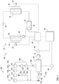
- FIG. 1 is a schematic illustration of a transport refrigeration system having a multi-fuel distribution system in accordance with the disclosure.
- a transport refrigeration system 20 includes a refrigeration unit 22, an electric generation device 24, an engine (prime mover) 26 for driving the electric generation device 24, and a controller 30.
- the refrigeration unit 22 functions, under the control of the controller 30, to establish and regulate a desired product storage temperature within a refrigerated cargo space wherein a perishable product is stored during transport and to maintain the product storage temperature within a specified temperature range.
- the refrigerated cargo space may be the cargo box of a trailer, a truck, a seaboard shipping container or an intermodal container wherein perishable cargo, such as, for example, produce, meat, poultry, fish, dairy products, cut flowers, and other fresh or frozen perishable products, is stowed for transport.
- the transport refrigeration unit 22 includes a refrigerant compression device 32, a refrigerant heat rejection heat exchanger 34, an expansion device 36, and a refrigerant heat absorption heat exchanger 38 connected in refrigerant flow communication in a closed loop refrigerant circuit and arranged in a conventional refrigeration cycle.
- the refrigeration unit 22 also includes one or more fans 40 associated with the refrigerant heat rejection heat exchanger 34 and driven by fan motor(s) 42 and one or more fans 44 associated with the refrigerant heat absorption heat exchanger 38 and driven by fan motor(s) 46.
- the refrigeration unit 22 may also include an electric resistance heater 48 associated with the refrigerant heat absorption heat exchanger 38. It is to be understood that other components (not shown) may be incorporated into the refrigerant circuit as desired, including for example, but not limited to, a suction modulation valve, a receiver, a filter/dryer, an economizer circuit.
- the refrigerant heat rejection heat exchanger 34 may, for example, comprise one or more refrigerant conveying coiled tubes or one or more tube banks formed of a plurality of refrigerant conveying tubes extending between respective inlet and outlet manifolds.
- the fan(s) 40 are operative to pass air, typically ambient air, across the tubes of the refrigerant heat rejection heat exchanger 34 to cool refrigerant vapor passing through the tubes.
- the refrigerant heat rejection heat exchanger 34 may operate either as a refrigerant condenser, such as if the refrigeration unit 22 is operating in a subcritical refrigerant cycle or as a refrigerant gas cooler, such as if the refrigeration unit 22 is operating in a transcritical cycle.
- the refrigerant heat absorption heat exchanger 38 may, for example, also comprise one or more refrigerant conveying coiled tubes or one or more tube banks formed of a plurality of refrigerant conveying tubes extending between respective inlet and outlet manifolds.
- the fan(s) 44 are operative to pass air drawn from the temperature controlled cargo box across the tubes of the refrigerant heat absorption heat exchanger 38 to heat and evaporate refrigerant liquid passing through the tubes and cool the air.
- the air cooled in traversing the refrigerant heat rejection heat exchanger 38 is supplied back to the temperature controlled cargo box.
- air when used herein with reference to the atmosphere within the cargo box includes mixtures of air with other gases, such as for example, but not limited to, nitrogen or carbon dioxide, sometimes introduced into a refrigerated cargo box for transport of perishable produce.
- the refrigerant compression device 32 may comprise a single-stage or multiple-stage compressor such as, for example, a reciprocating compressor or a scroll compressor.
- the compression device 32 has a compression mechanism (not shown) driven by an electric motor 50.
- the motor 50 may be disposed internally within the compressor with a drive shaft interconnected with a shaft of the compression mechanism, all sealed within a common housing of the compression device 32.
- the refrigeration system 20 also includes a controller 30 configured for controlling operation of the refrigeration system 20 including, but not limited to, operation of various components of the refrigerant unit 22 to provide and maintain a desired thermal environment within the cargo box of the truck or trailer, that is within the temperature controlled space in which a perishable product is stowed.
- the controller 30 may be an electronic controller including a microprocessor and an associated memory bank.
- the controller 30 controls operation of various components of the refrigerant unit 22, such as the refrigerant compression device 32 and its associated drive motor 50, the fan motors 42, 46 and the electric resistance heater 48.
- the controller 30 selectively operates the engine 26 in accordance with the independent claims 1 and 9, typically through an electronic engine controller 54 operatively associated with the engine 26.
- the refrigeration unit 22 has a plurality of power demand loads, including, but not limited to, the compression device drive motor 50, the drive motor 42 for the fan 40 associated with the refrigerant heat rejection heat exchanger 34, and the drive motor 46 for the fan 44 associated with the refrigerant heat absorption heat exchanger 38.
- the electric resistance heater 48 also constitutes a power demand load.
- the electric resistance heater may be selectively operated by the controller 30 whenever a control temperature within the temperature controlled cargo box drops below a preset lower temperature limit, which may occur in a cold ambient environment. In such an event the controller 30 would activate the electric resistance heater 48 to heat air circulated over the electric resistance heater by the fan(s) 44 associated with the refrigerant heat absorption heat exchanger 38.
- the engine 26 is an on-board fossil-fuel engine according to the independent claim 1 that drives the electric generation device 24, which generates electrical power.
- the engine 26 is a multi-fuel capable engine that can run on propane, compressed natural gas, liquefied natural gas, or gasoline.
- the engine 26 may be a spark ignited engine, which are commonly used in industrial applications, such as, for example fork lifts or generator sets.
- the drive shaft of the engine drives the shaft of the electric generation device 24.
- the electric generation device 24 may comprise a single on-board, engine driven AC generator configured to generate alternating current (AC) power including at least one AC voltage at one or more frequencies.
- the electric generation device 24 may, for example, be a permanent magnet AC generator or a synchronous AC generator.
- the electric generation device 24 may comprise a single on-board, engine driven DC generator configured to generate direct current (DC) power at at least one voltage. Some electric generation devices may have internal voltage regulators while other electric generation devices do not.
- the refrigeration system 20 has a voltage sensor 28 to sense the voltage of the electric generation device 24.
- each of the fan motors 42, 46 and the compression device drive motor 50 may be an AC motor or a DC motor, it is to be understood that various power converters 52, such as AC to DC rectifiers, DC to AC inverters, AC to AC voltage/frequency converters, and DC to DC voltage converters, may be employed in connection with the electric generation device 24 as appropriate.
- the fuel is delivered to the engine 26 through a multi-fuel distribution system 100.
- the fuel systems according to the independent claim 1 includes a propane fuel system 120, a compressed natural gas fuel system 130, a liquefied natural gas fuel system 140, and a gasoline fuel system 150.
- the fuel systems are separate modules, each module being removably connected to the engine 26, meaning that all four different fuel system types may be included in the multi-fuel distribution system 100 or any combination of the four different fuel systems according to claim 1.
- a fuel system can be removed without affecting the other fuels systems.
- the controller 30 is configured to command a fuel to the engine 26 from one of the fuel systems.
- the controller 30 is also configured to adjust the operation of the engine 26 in response to the fuel commanded.
- the fuel is commanded directly on the refrigeration unit 22.
- the fuel selection may also be controlled automatically by the controller 30 based on a selected fuel variable, such as, for example, fuel price.
- the common fuel regulation system 170 includes: an engine lock off valve 174; a vaporizer 176 fluidly connected to the engine lock off valve 174; and an electronic fuel pressure regulator 178 fluidly connecting the vaporizer 176 to the engine 26.
- the propane fuel system 120, the compressed natural gas fuel system 130, and the liquefied natural gas fuel system 140 are each fluidly connected to the engine lock off valve 174.
- the electronic pressure regulator 178 is configured to adjust the fuel flow to the engine 26 in response to a command from the controller 30.
- Adjusting the fuel flow may include allowing the fuel commanded by the controller 30 to proceed to the engine 26, while preventing the non-commanded fuels from proceeding to the engine 26.
- the engine lock off valve 174 is configured to shut off the fuel flow to the engine 26 when the engine 26 is not in the start sequence or running.
- the propane fuel system 120 comprises: a propane tank 121; the engine lock off valve 174 fluidly connected to the propane tank 121; a vaporizer 176 fluidly connected to the engine lock off valve 174; and an electronic fuel pressure regulator 178 fluidly connecting the vaporizer 176 to the engine 26.
- the engine lock off valve 174, the vaporizer 176, and the electronic fuel pressure regulator 178 are part of the common fuel regulation system 170, as discussed above.
- the propane tank 121 can be removed from the multi-fuel distribution system 100 when the propane fuel system 120 is not needed. If the propane fuel system 120, the compressed natural gas fuel system 130, and the liquefied natural gas fuel system 140 are all not needed, these fuel systems can be removed from the multi-fuel distribution system 100 along with the common fuel regulation system 170.
- the compressed natural gas fuel system 130 comprises: a compressed natural gas tank 131; a tank lock off valve 132 fluidly connected to the compressed natural gas tank 131; a high pressure regulator 134 fluidly connected to the tank lock off valve 132; a low pressure regulator 136 fluidly connected to the high pressure regulator 134; an engine lock off valve 174 fluidly connected to the low pressure regulator 136; a vaporizer 176 fluidly connected to the engine lock off valve 174; and an electronic fuel pressure regulator 178 fluidly connecting the vaporizer 176 to the engine 26.
- the high pressure regulator 134 and the low pressure regulator 136 step down (i.e.
- the engine lock off valve 174, the vaporizer 176, and the electronic fuel pressure regulator 178 are part of the common fuel regulation system 170, as discussed above.
- the compressed natural gas tank 131, tank lock off valve 132, high pressure regulator 134, and low pressure regulator 136 can be removed from the multi-fuel distribution system 100 when compressed natural gas fuel system 130 is not needed. If the propane fuel system 120, the compressed natural gas fuel system 130, and the liquefied natural gas fuel system 140 are all not needed, these fuel systems can be removed from the multi-fuel distribution system 100 along with the common fuel regulation system 170.
- the liquefied natural gas fuel system 140 comprises: a liquefied natural gas tank 141; an engine lock off valve 174 fluidly connected to the liquefied natural gas tank 141; a vaporizer or regulator 176 fluidly connected to the engine lock off valve 174; and an electronic fuel pressure regulator 178 fluidly connecting the vaporizer 176 to the engine 26.
- the vaporizer 176 may be a vaporizer and/or a regulator.
- the engine lock off valve 174, the vaporizer 176, and the electronic fuel pressure regulator 178 are part of the common fuel regulation system 170, as discussed above.
- the liquefied natural gas tank 141 can be removed from the multi-fuel distribution system 100 when the liquefied natural gas fuel system 140 is not needed. If the propane fuel system 120, the compressed natural gas fuel system 130, and the liquefied natural gas fuel system 140 are all not needed, these fuel systems can be removed from the multi-fuel distribution system 100 along with the common fuel regulation system 170.
- the gasoline fuel system 150 comprises a gasoline tank 151; a fuel pump 152 fluidly connected to the gasoline tank 151; a fuel pressure manifold 154 fluidly connected to the fuel pump 152; a fuel return line 158 fluidly connecting the fuel pressure manifold 154 to the gasoline tank 151; and a fuel injector 156 fluidly connecting the fuel pressure manifold 154 to the engine 26.
- the fuel pump 152 pumps gasoline through the gasoline fuel system 150 and the fuel pressure manifold 154 regulates the pressure of the gasoline in the gasoline fuel system 150.
- the return line 158 returns gasoline from the fuel pressure manifold 154 to the gasoline tank 151 as required.
- the gasoline tank 151, fuel pump 152, fuel pressure manifold 154, and fuel return line 158 can be removed from the multi-fuel distribution system 100 when the gasoline fuel system 150 is not needed.
- the fuel injectors 156 can remain in the engine 26.
- the engine 26 has two separate fuel inlet points, one at the fuel injectors 156 for the gasoline fuel system 150 and another at the electronic fuel pressure regulator 178 for the propane fuel system 120, the compressed natural gas fuel system 130, and the liquefied natural gas fuel system 140. As mentioned above the fuel systems are each removable.
- the controller 30 adjusts the performance of the engine 26 based on the desired fuel. For example, the controller 30 may adjust fuel delivery rate and/ or spark advance in the engine 26 depending on the fuel. The controller 26 will also control which fuel system is supplying the engine 26 with fuel.
- a multi-fuel distribution system creates flexibility for the operators of transport refrigeration systems and allows the operators to run the engine of the refrigeration unit on a variety of fuels. Also advantageously, a multi-fuel system creates efficiency allowing operators of transport refrigeration systems to fuel the refrigeration unit with the same fuel they use to fill up their truck, which helps to avoid multiple stops for different fuels. Further advantageously, due to the flexibility of a multi-fuel system, the refrigeration system could be mixed and matched daily with different trucks without a need to change the engine of the refrigeration unit.
Landscapes
- Engineering & Computer Science (AREA)
- Chemical & Material Sciences (AREA)
- Mechanical Engineering (AREA)
- General Engineering & Computer Science (AREA)
- Combustion & Propulsion (AREA)
- Oil, Petroleum & Natural Gas (AREA)
- General Chemical & Material Sciences (AREA)
- Chemical Kinetics & Catalysis (AREA)
- Physics & Mathematics (AREA)
- Thermal Sciences (AREA)
- Health & Medical Sciences (AREA)
- Public Health (AREA)
- Transportation (AREA)
- Output Control And Ontrol Of Special Type Engine (AREA)
Description
- The embodiments herein generally relate to transport refrigeration systems and more specifically, the fuel systems of such transport refrigeration systems.
- Typically, cold chain distribution systems are used to transport and distribute cargo, or more specifically perishable goods and environmentally sensitive goods (herein referred to as perishable goods) that may be susceptible to temperature, humidity, and other environmental factors. Perishable goods may include but are not limited to fruits, vegetables, grains, beans, nuts, eggs, dairy, seed, flowers, meat, poultry, fish, ice, and pharmaceuticals. Advantageously, cold chain distribution systems allow perishable goods to be effectively transported and distributed without damage or other undesirable effects.
- Refrigerated trucks and trailers are commonly used to transport perishable goods in a cold chain distribution system. A transport refrigeration system is mounted to the truck or to the trailer in operative association with a cargo space defined within the truck or trailer for maintaining a controlled temperature environment within the cargo space.
- Conventionally, transport refrigeration systems used in connection with refrigerated trucks and refrigerated trailers include a transport refrigeration unit having a refrigerant compressor, a condenser with one or more associated condenser fans, an expansion device, and an evaporator with one or more associated evaporator fans, which are connected via appropriate refrigerant lines in a closed refrigerant flow circuit. Air or an air/ gas mixture is drawn from the interior volume of the cargo space by means of the evaporator fan(s) associated with the evaporator, passed through the airside of the evaporator in heat exchange relationship with refrigerant whereby the refrigerant absorbs heat from the air, thereby cooling the air. The cooled air is then supplied back to the cargo space.
- On commercially available transport refrigeration systems used in connection with refrigerated trucks and refrigerated trailers, the compressor, and typically other components of the transport refrigeration unit, must be powered during transit by a prime mover (engine). In mechanically driven transport refrigeration systems the compressor is driven by the engine, either through a direct mechanical coupling or a belt drive, and other components, such as the condenser and evaporator fans are belt driven.
-
US 2011/265506 A1 discloses an electrically-powered air conditioning and heating system for mobile vehicles. Multiple variable-speed compressors operate in series and parallel modes giving an exceptionally wide range of operating capacity making the system suitable for combined on-highway and no-idle use in trucks. In series mode, the single-stage compressors function like a two-stage compressors for increased energy efficiency. A unique power control and storage system has multi-voltage input and output capability without the use of DC-DC or DC-AC converters. A battery management system is incorporated which is compatible with all advanced battery technologies and offers cell-level charge and discharge control. -
US 2013/248165 A1 describes a mobile environment-controlled unit comprising a chassis, a compartment supported by the chassis, and an environmental-control system in environmental communication with the compartment. The environmental-control system is configured to control an environmental parameter of the compartment. The environmental-control system includes an AC Alternator and a controller. The AC alternator is powered by an internal combustion engine and supplies electrical power for the environmental-control system. The controller is configured to monitor the environmental parameter of the compartment, monitor one or more electrical parameters of the AC alternator, control the environmental-control system based on the monitored environmental parameter, and control the AC alternator based on the monitored parameters of the alternator, - Document
WO2014/086414A1 discloses an integrated fuel feed system for a dual fuel marine engine, the system feeding compressed natural gas, otherwise known as CNG, as at least one of the fuels for the engine, the system being integrated into or onto a vessel for marine transportation of CNG, wherein or whereon the CNG is contained in interconnected pressure vessels, wherein the CNG used as at least one of the fuels is extracted directly from one or more of the pressure vessels. - Document
US5259198A discloses a refrigeration system comprising a cryogenic cooler containing a fuel in a cryogenic state. A heat exchanger transfers heat within a conditioned space. A second heat exchanger transfers heat from the cooler. The two heat exchangers are connected together to form a cooling cycle. - Document
KR20110109453A - An "all electric" transport refrigeration system for a refrigerated trailer application is also commercially available through Carrier Corporation. In the all electric transport refrigeration system, an engine carried on and considered part of the transport refrigeration system, drives an AC synchronous generator that generates AC power. The generated AC power is used to power an electric compressor motor for driving the refrigerant compressor of the transport refrigeration unit and also powering electric AC fan motors for driving the condenser and evaporator motors and electric heaters associated with the evaporator. For example,
U.S. Pat. No. 6,223,546 discloses an all electric transport refrigeration system, which comprises all the technical features from the preamble of the independent claims 1 and 9. - In the case of refrigerated trailers, the engine typically comprises a diesel engine carried on and considered part of the transport refrigeration system. However in many cases, while the engine for the refrigeration unit may be diesel, the engine of the truck may be powered by another fuel, such as, for example gasoline, natural gas, or propane. If the engine runs on a different fuel than the truck, then it will lead to multiple stops to pick up different fuels at different locations. Incurring multiple stops to fuel the truck and the engine at different locations is a waste of valuable time and thus, a more efficient solution is desired.
- The present invention is disclosed in the independent claims 1 and 9. Further embodiments are disclosed in the dependent claims.
- All the features of the independent claims 1 and 9 are obligatory features for all the embodiments of the present invention.
- Further embodiments of the transport refrigeration system may include a common fuel regulation system having: an engine lock off valve; a vaporizer fluidly connected to the engine lock off valve; and an electronic fuel pressure regulator fluidly connecting the vaporizer to the engine. The propane fuel system, compressed natural gas fuel system, and the liquefied natural gas system are fluidly connected to engine lock off valve. The electronic pressure regulator is configured to adjust the fuel flow to the engine in response to a command from the controller.
- In addition to one or more of the features described above, or as an alternative, further embodiments of the transport refrigeration system may include that the propane fuel system further includes: a propane tank; an engine lock off valve fluidly connected to the propane tank; a vaporizer fluidly connected to the engine lock off valve; and an electronic fuel pressure regulator fluidly connecting the vaporizer to the engine.
- In addition to one or more of the features described above, or as an alternative, further embodiments of the transport refrigeration system may include that the compressed natural gas fuel system further includes: a compressed natural gas tank; a tank lock off valve fluidly connected to the compressed natural gas tank; a high pressure regulator fluidly connected to the tank lock off valve; a low pressure regulator fluidly connected to the high pressure regulator; an engine lock off valve fluidly connected to the low pressure regulator; a vaporizer fluidly connected to the engine lock off valve; and an electronic fuel pressure regulator fluidly connecting the vaporizer to the engine.
- In addition to one or more of the features described above, or as an alternative, further embodiments of the transport refrigeration system may include that the liquefied natural gas fuel system further includes: a liquefied natural gas tank; an engine lock off valve fluidly connected to the liquefied natural gas tank; a vaporizer fluidly connected to the engine lock off valve; and an electronic fuel pressure regulator fluidly connecting the vaporizer to the engine.
- In addition to one or more of the features described above, or as an alternative, further embodiments of the transport refrigeration system may include that the gasoline fuel system further includes: a gasoline tank; a fuel pump fluidly connected to the gasoline tank; a fuel pressure manifold fluidly connected to the fuel pump; a fuel return line fluidly connecting the fuel pressure manifold to the gasoline tank; and a fuel injector fluidly connecting the fuel pressure manifold to the engine.
- Further embodiments of the method may include regulating, using a common fuel regulation system, fuel flow into the engine. The common fuel regulation system having: an engine lock off valve; a vaporizer fluidly connected to the engine lock off valve; and an electronic fuel pressure regulator fluidly connecting the vaporizer to the engine. The propane fuel system, compressed natural gas fuel system, and the liquefied natural gas system are fluidly connected to engine lock off valve. The electronic pressure regulator is configured to adjust the fuel flow to the engine in response to a command from the controller.
- In addition to one or more of the features described above, or as an alternative, further embodiments of the method may include that the propane fuel system further includes: a propane tank; an engine lock off valve fluidly connected to the propane tank; a vaporizer fluidly connected to the engine lock off valve; and an electronic fuel pressure regulator fluidly connecting the vaporizer to the engine.
- In addition to one or more of the features described above, or as an alternative, further embodiments of the method may include that the compressed natural gas fuel system further includes: a compressed natural gas tank; a tank lock off valve fluidly connected to the compressed natural gas tank; a high pressure regulator fluidly connected to the tank lock off valve; a low pressure regulator fluidly connected to the high pressure regulator; an engine lock off valve fluidly connected to the low pressure regulator; a vaporizer fluidly connected to the engine lock off valve; and an electronic fuel pressure regulator fluidly connecting the vaporizer to the engine.
- In addition to one or more of the features described above, or as an alternative, further embodiments of the method may include that the liquefied natural gas fuel system further includes: a liquefied natural gas tank; an engine lock off valve fluidly connected to the liquefied natural gas tank; a vaporizer fluidly connected to the engine lock off valve; and an electronic fuel pressure regulator fluidly connecting the vaporizer to the engine.
- In addition to one or more of the features described above, or as an alternative, further embodiments of the method may include that the gasoline fuel system further includes: a gasoline tank; a fuel pump fluidly connected to the gasoline tank; a fuel pressure manifold fluidly connected to the fuel pump; a fuel return line fluidly connecting the fuel pressure manifold to the gasoline tank; and a fuel injector fluidly connecting the fuel pressure manifold to the engine.
- According to one embodiment, a controller of a transport refrigeration system according to claim 1, this embodiment comprising in fact all the features of claim 1, is provided.
- In addition to one or more of the features described above, further embodiments of the controller may include that the operation further include: regulating fuel flow into the engine with a common fuel regulation system.
- Technical effects of embodiments of the present disclosure include fueling an engine of a transport refrigeration unit with propane, compressed natural gas, liquefied natural gas, or gasoline, wherein the gasoline fuel system, the propane fuel system and the natural gas fuel system are separate modules being removably connected to the engine.
- These features and elements as well as the operation thereof will become more apparent in light of the following description and the accompanying drawings. It should be understood, however, that the following description and drawings are intended to be illustrative and explanatory in nature and non-limiting.
- The present invention is disclosed in the independent claims 1 and 9. All the features of the independent claims 1 and 9 are obligatory features for all the embodiments of the present invention.
- The subject matter which is regarded as the disclosure is pointed out and distinctly claimed in the claims. The foregoing and other features and advantages of the disclosure are apparent from the following detailed description taken in conjunction with the accompanying drawing in which:
-
FIG. 1 is a schematic illustration of a transport refrigeration system having a multi-fuel distribution system in accordance with the disclosure. - Referring to
FIG. 1 , atransport refrigeration system 20 includes a refrigeration unit 22, anelectric generation device 24, an engine (prime mover) 26 for driving theelectric generation device 24, and acontroller 30. The refrigeration unit 22 functions, under the control of thecontroller 30, to establish and regulate a desired product storage temperature within a refrigerated cargo space wherein a perishable product is stored during transport and to maintain the product storage temperature within a specified temperature range. The refrigerated cargo space may be the cargo box of a trailer, a truck, a seaboard shipping container or an intermodal container wherein perishable cargo, such as, for example, produce, meat, poultry, fish, dairy products, cut flowers, and other fresh or frozen perishable products, is stowed for transport. - The transport refrigeration unit 22 includes a
refrigerant compression device 32, a refrigerant heatrejection heat exchanger 34, an expansion device 36, and a refrigerant heat absorption heat exchanger 38 connected in refrigerant flow communication in a closed loop refrigerant circuit and arranged in a conventional refrigeration cycle. The refrigeration unit 22 also includes one ormore fans 40 associated with the refrigerant heatrejection heat exchanger 34 and driven by fan motor(s) 42 and one or more fans 44 associated with the refrigerant heat absorption heat exchanger 38 and driven by fan motor(s) 46. The refrigeration unit 22 may also include anelectric resistance heater 48 associated with the refrigerant heat absorption heat exchanger 38. It is to be understood that other components (not shown) may be incorporated into the refrigerant circuit as desired, including for example, but not limited to, a suction modulation valve, a receiver, a filter/dryer, an economizer circuit. - The refrigerant heat
rejection heat exchanger 34 may, for example, comprise one or more refrigerant conveying coiled tubes or one or more tube banks formed of a plurality of refrigerant conveying tubes extending between respective inlet and outlet manifolds. The fan(s) 40 are operative to pass air, typically ambient air, across the tubes of the refrigerant heatrejection heat exchanger 34 to cool refrigerant vapor passing through the tubes. The refrigerant heatrejection heat exchanger 34 may operate either as a refrigerant condenser, such as if the refrigeration unit 22 is operating in a subcritical refrigerant cycle or as a refrigerant gas cooler, such as if the refrigeration unit 22 is operating in a transcritical cycle. - The refrigerant heat absorption heat exchanger 38 may, for example, also comprise one or more refrigerant conveying coiled tubes or one or more tube banks formed of a plurality of refrigerant conveying tubes extending between respective inlet and outlet manifolds. The fan(s) 44 are operative to pass air drawn from the temperature controlled cargo box across the tubes of the refrigerant heat absorption heat exchanger 38 to heat and evaporate refrigerant liquid passing through the tubes and cool the air. The air cooled in traversing the refrigerant heat rejection heat exchanger 38 is supplied back to the temperature controlled cargo box. It is to be understood that the term "air" when used herein with reference to the atmosphere within the cargo box includes mixtures of air with other gases, such as for example, but not limited to, nitrogen or carbon dioxide, sometimes introduced into a refrigerated cargo box for transport of perishable produce.
- The
refrigerant compression device 32 may comprise a single-stage or multiple-stage compressor such as, for example, a reciprocating compressor or a scroll compressor. Thecompression device 32 has a compression mechanism (not shown) driven by an electric motor 50. In an embodiment, the motor 50 may be disposed internally within the compressor with a drive shaft interconnected with a shaft of the compression mechanism, all sealed within a common housing of thecompression device 32. - The
refrigeration system 20 also includes acontroller 30 configured for controlling operation of therefrigeration system 20 including, but not limited to, operation of various components of the refrigerant unit 22 to provide and maintain a desired thermal environment within the cargo box of the truck or trailer, that is within the temperature controlled space in which a perishable product is stowed. Thecontroller 30 may be an electronic controller including a microprocessor and an associated memory bank. Thecontroller 30 controls operation of various components of the refrigerant unit 22, such as therefrigerant compression device 32 and its associated drive motor 50, thefan motors 42, 46 and theelectric resistance heater 48. Thecontroller 30 selectively operates theengine 26 in accordance with the independent claims 1 and 9, typically through an electronic engine controller 54 operatively associated with theengine 26. - The refrigeration unit 22 has a plurality of power demand loads, including, but not limited to, the compression device drive motor 50, the drive motor 42 for the
fan 40 associated with the refrigerant heatrejection heat exchanger 34, and thedrive motor 46 for the fan 44 associated with the refrigerant heat absorption heat exchanger 38. In the depicted embodiment, theelectric resistance heater 48 also constitutes a power demand load. The electric resistance heater may be selectively operated by thecontroller 30 whenever a control temperature within the temperature controlled cargo box drops below a preset lower temperature limit, which may occur in a cold ambient environment. In such an event thecontroller 30 would activate theelectric resistance heater 48 to heat air circulated over the electric resistance heater by the fan(s) 44 associated with the refrigerant heat absorption heat exchanger 38. - The
engine 26 is an on-board fossil-fuel engine according to the independent claim 1 that drives theelectric generation device 24, which generates electrical power. Theengine 26 is a multi-fuel capable engine that can run on propane, compressed natural gas, liquefied natural gas, or gasoline. Theengine 26 may be a spark ignited engine, which are commonly used in industrial applications, such as, for example fork lifts or generator sets. The drive shaft of the engine drives the shaft of theelectric generation device 24. In an electrically powered embodiment of thetransport refrigeration unit 20, theelectric generation device 24 may comprise a single on-board, engine driven AC generator configured to generate alternating current (AC) power including at least one AC voltage at one or more frequencies. In an embodiment, theelectric generation device 24 may, for example, be a permanent magnet AC generator or a synchronous AC generator. In another embodiment, theelectric generation device 24 may comprise a single on-board, engine driven DC generator configured to generate direct current (DC) power at at least one voltage. Some electric generation devices may have internal voltage regulators while other electric generation devices do not. Therefrigeration system 20 has avoltage sensor 28 to sense the voltage of theelectric generation device 24. As each of thefan motors 42, 46 and the compression device drive motor 50 may be an AC motor or a DC motor, it is to be understood thatvarious power converters 52, such as AC to DC rectifiers, DC to AC inverters, AC to AC voltage/frequency converters, and DC to DC voltage converters, may be employed in connection with theelectric generation device 24 as appropriate. - The fuel is delivered to the
engine 26 through amulti-fuel distribution system 100. - The fuel systems according to the independent claim 1 includes a
propane fuel system 120, a compressed natural gas fuel system 130, a liquefied natural gas fuel system 140, and a gasoline fuel system 150. The fuel systems are separate modules, each module being removably connected to theengine 26, meaning that all four different fuel system types may be included in themulti-fuel distribution system 100 or any combination of the four different fuel systems according to claim 1. A fuel system can be removed without affecting the other fuels systems. Further, thecontroller 30 is configured to command a fuel to theengine 26 from one of the fuel systems. Thecontroller 30 is also configured to adjust the operation of theengine 26 in response to the fuel commanded. The fuel is commanded directly on the refrigeration unit 22. The fuel selection may also be controlled automatically by thecontroller 30 based on a selected fuel variable, such as, for example, fuel price. - As seen in
FIG. 1 , thepropane fuel system 120, the compressed natural gas fuel system 130, and the liquefied natural gas fuel system 140 share a common fuel regulation system 170. The common fuel regulation system 170 includes: an engine lock offvalve 174; avaporizer 176 fluidly connected to the engine lock offvalve 174; and an electronic fuel pressure regulator 178 fluidly connecting thevaporizer 176 to theengine 26. Thepropane fuel system 120, the compressed natural gas fuel system 130, and the liquefied natural gas fuel system 140 are each fluidly connected to the engine lock offvalve 174. The electronic pressure regulator 178 is configured to adjust the fuel flow to theengine 26 in response to a command from thecontroller 30. Adjusting the fuel flow may include allowing the fuel commanded by thecontroller 30 to proceed to theengine 26, while preventing the non-commanded fuels from proceeding to theengine 26. The engine lock offvalve 174 is configured to shut off the fuel flow to theengine 26 when theengine 26 is not in the start sequence or running. - In the illustrated embodiment, the
propane fuel system 120 comprises: apropane tank 121; the engine lock offvalve 174 fluidly connected to thepropane tank 121; avaporizer 176 fluidly connected to the engine lock offvalve 174; and an electronic fuel pressure regulator 178 fluidly connecting thevaporizer 176 to theengine 26. The engine lock offvalve 174, thevaporizer 176, and the electronic fuel pressure regulator 178 are part of the common fuel regulation system 170, as discussed above. Thepropane tank 121 can be removed from themulti-fuel distribution system 100 when thepropane fuel system 120 is not needed. If thepropane fuel system 120, the compressed natural gas fuel system 130, and the liquefied natural gas fuel system 140 are all not needed, these fuel systems can be removed from themulti-fuel distribution system 100 along with the common fuel regulation system 170. - In the illustrated embodiment, the compressed natural gas fuel system 130 comprises: a compressed
natural gas tank 131; a tank lock off valve 132 fluidly connected to the compressednatural gas tank 131; ahigh pressure regulator 134 fluidly connected to the tank lock off valve 132; alow pressure regulator 136 fluidly connected to thehigh pressure regulator 134; an engine lock offvalve 174 fluidly connected to thelow pressure regulator 136; avaporizer 176 fluidly connected to the engine lock offvalve 174; and an electronic fuel pressure regulator 178 fluidly connecting thevaporizer 176 to theengine 26. Thehigh pressure regulator 134 and thelow pressure regulator 136 step down (i.e. reduce) the pressure of the compressed natural gas, which is stored at a high pressure in the compressednatural gas tank 131 but needs to be depressurized for consumption by theengine 26. The engine lock offvalve 174, thevaporizer 176, and the electronic fuel pressure regulator 178 are part of the common fuel regulation system 170, as discussed above. The compressednatural gas tank 131, tank lock off valve 132,high pressure regulator 134, andlow pressure regulator 136 can be removed from themulti-fuel distribution system 100 when compressed natural gas fuel system 130 is not needed. If thepropane fuel system 120, the compressed natural gas fuel system 130, and the liquefied natural gas fuel system 140 are all not needed, these fuel systems can be removed from themulti-fuel distribution system 100 along with the common fuel regulation system 170. - In the illustrated embodiment, the liquefied natural gas fuel system 140 comprises: a liquefied
natural gas tank 141; an engine lock offvalve 174 fluidly connected to the liquefiednatural gas tank 141; a vaporizer orregulator 176 fluidly connected to the engine lock offvalve 174; and an electronic fuel pressure regulator 178 fluidly connecting thevaporizer 176 to theengine 26. Thevaporizer 176 may be a vaporizer and/or a regulator. The engine lock offvalve 174, thevaporizer 176, and the electronic fuel pressure regulator 178 are part of the common fuel regulation system 170, as discussed above. The liquefiednatural gas tank 141 can be removed from themulti-fuel distribution system 100 when the liquefied natural gas fuel system 140 is not needed. If thepropane fuel system 120, the compressed natural gas fuel system 130, and the liquefied natural gas fuel system 140 are all not needed, these fuel systems can be removed from themulti-fuel distribution system 100 along with the common fuel regulation system 170. - In the illustrated embodiment, the gasoline fuel system 150 comprises a
gasoline tank 151; afuel pump 152 fluidly connected to thegasoline tank 151; afuel pressure manifold 154 fluidly connected to thefuel pump 152; afuel return line 158 fluidly connecting thefuel pressure manifold 154 to thegasoline tank 151; and a fuel injector 156 fluidly connecting thefuel pressure manifold 154 to theengine 26. Thefuel pump 152 pumps gasoline through the gasoline fuel system 150 and thefuel pressure manifold 154 regulates the pressure of the gasoline in the gasoline fuel system 150. Thereturn line 158 returns gasoline from thefuel pressure manifold 154 to thegasoline tank 151 as required. Thegasoline tank 151,fuel pump 152,fuel pressure manifold 154, andfuel return line 158 can be removed from themulti-fuel distribution system 100 when the gasoline fuel system 150 is not needed. The fuel injectors 156 can remain in theengine 26. - Further, the
engine 26 has two separate fuel inlet points, one at the fuel injectors 156 for the gasoline fuel system 150 and another at the electronic fuel pressure regulator 178 for thepropane fuel system 120, the compressed natural gas fuel system 130, and the liquefied natural gas fuel system 140. As mentioned above the fuel systems are each removable. Thecontroller 30 adjusts the performance of theengine 26 based on the desired fuel. For example, thecontroller 30 may adjust fuel delivery rate and/ or spark advance in theengine 26 depending on the fuel. Thecontroller 26 will also control which fuel system is supplying theengine 26 with fuel. - Advantageously, a multi-fuel distribution system creates flexibility for the operators of transport refrigeration systems and allows the operators to run the engine of the refrigeration unit on a variety of fuels. Also advantageously, a multi-fuel system creates efficiency allowing operators of transport refrigeration systems to fuel the refrigeration unit with the same fuel they use to fill up their truck, which helps to avoid multiple stops for different fuels. Further advantageously, due to the flexibility of a multi-fuel system, the refrigeration system could be mixed and matched daily with different trucks without a need to change the engine of the refrigeration unit.
- While the disclosure has been described in detail in connection with only a limited number of embodiments, it should be readily understood that the disclosure is not limited to such disclosed embodiments. Rather, the disclosure can be modified to incorporate any number of variations, alterations, substitutions or equivalent arrangements not heretofore described, but which are within the scope of the claims.
- Additionally, while various embodiments of the disclosure have been described, it is to be understood that aspects of the disclosure may include only some of the described embodiments. Accordingly, the disclosure is not to be seen as limited by the foregoing description, but is only limited by the scope of the appended claims.
Claims (14)
- A transport refrigeration system (20) comprising:an engine (26);a refrigeration unit (22) powered by the engine (26); whereinthe engine (26) is a multi-fuel capable engine (26) and the transport refrigeration system (20) further comprises:a gasoline fuel system (150) operably connected to the engine (26);a propane fuel system (120) operably connected to the engine (26);a natural gas fuel system (130, 140) operably connected to the engine (26), the natural gas fuel system (130, 140) including at least one of a compressed natural gas fuel system (130) and a liquefied natural gas fuel system (140); anda controller (30) configured to command a fuel to the engine (26) from the gasoline fuel system (150), the propane fuel system (120) or the natural gas fuel system (130, 140), the controller (30) being configured to adjust the operation of the engine (26) in response to the fuel commanded;characterized in that the gasoline fuel system (150), the propane fuel system (120) and the natural gas fuel system (130, 140) are separate modules being removably connected to the engine (26).
- The transport refrigeration system (20) of claim 1, further comprising:
a common fuel regulation system (170) comprising:an engine lock off valve (174);a vaporizer (176) fluidly connected to the engine lock off valve (174); andan electronic fuel pressure regulator (178) fluidly connecting the vaporizer (176) to the engine (26);wherein the propane fuel system (120), thecompressed natural gas fuel system (130), and the liquefied natural gas system (140) are fluidly connected to the engine lock off valve (174),wherein the electronic fuel pressure regulator (178) is configured to adjust the fuel flow to the engine (26) in response to a command from the controller (30). - The transport refrigeration system (20) of claim 1, wherein the propane fuel system (120) further comprises:a propane tank (121);an engine lock off valve (174) fluidly connected to the propane tank (121);a vaporizer (176) fluidly connected to the engine lock off valve (174); andan electronic fuel pressure regulator (178) fluidly connecting the vaporizer (176) to the engine (26).
- The transport refrigeration system (20) of claim 1, wherein the compressed natural gas fuel system (130) further comprises:a compressed natural gas tank (131);a tank lock off valve (132) fluidly connected to the compressed natural gas tank (131);a high pressure regulator (134) fluidly connected to the tank lock off valve (132);a low pressure regulator (136) fluidly connected to the high pressure regulator (134);an engine lock off valve (174) fluidly connected to the low pressure regulator (136);a vaporizer (176) fluidly connected to the engine lock off valve (174); andan electronic fuel pressure regulator (178) fluidly connecting the vaporizer (176) to the engine (26).
- The transport refrigeration system (20) of claim 1, wherein the liquefied natural gas fuel system (140) further comprises:a liquefied natural gas tank (141),an engine lock off valve (174) fluidly connected to the liquefied natural gas tank (141),a vaporizer (176) fluidly connected to the engine lock off valve (174); andan electronic fuel pressure regulator (178) fluidly connecting the vaporizer (176) to the engine (26).
- The transport refrigeration system (20) of claim 1, wherein the gasoline fuel system (150) further comprises:a gasoline tank (151);a fuel pump (152) fluidly connected to the gasoline tank (151);a fuel pressure manifold (154) fluidly connected to the fuel pump (152);a fuel return line (158) fluidly connecting the fuel pressure manifold (154) to the gasoline tank (151); anda fuel injector (156) fluidly connecting the fuel pressure manifold (154) to the engine (26).
- The transport refrigeration system (20) of any of the preceding claims, wherein the controller (30) comprises:a processor;a memory comprising computer-executable instructions that, when executed by the processor, cause the processor to perform operations, the operations comprising:operating a multi-fuel capable engine (26);powering a refrigeration unit (22) with the engine (26);fueling the engine (26), using the gasoline fuel system (150), the propane fuel system (120) or the natural gas fuel system (130, 140); andcommanding a fuel to the engine (26) from the the gasoline fuel system (150), the propane fuel system (120) or the natural gas fuel system (130, 140), the controller (30) being configured to adjust the operation of the engine (26) in response to the fuel commanded,wherein the gasoline fuel system (150), the propane fuel system (120) and the natural gas fuel system (130, 140) are separate modules being removably connected to the engine (26).
- The transport refrigeration system (20) of claim 7, wherein the operations further comprise:regulating fuel flow into the engine (26) with the common fuel regulation system (170).
- A method of operating the transport refrigeration system (20) of claim 1, the method comprising:operating an engine (26);powering, using the engine (26), a refrigeration unit (22); whereinthe engine (26) is a multi-fuel capable engine (26) and the method further comprises:fueling the engine (26), using a gasoline fuel system (120) operably connected to the engine (26), a propane fuel system (150) operably connected to the engine (26), or a natural gas fuel system (130, 140) operably connected to the engine (26), the natural gas fuel system (130, 140) including at least one of a compressed natural gas fuel system (130) and a liquefied natural gas fuel system (140) ; andcommanding, using a controller (30), a fuel to the engine (26) from the gasoline fuel system (150), the propane fuel system (120), or the natural gas fuel system (130, 140), the controller (30) being configured to adjust the operation of the engine (26) in response to the fuel commanded;characterized in that the gasoline fuel system (150), the propane fuel system (120) and the natural gas fuel system (130, 140) are separate modules being removably connected to the engine (26).
- The method of claim 9, further comprising:
regulating, using a common fuel regulation system (170), fuel flow into the engine (26), the common fuel regulation system (170) comprising:an engine lock off valve (174);a vaporizer (176) fluidly connected to the engine lock off valve (174); andan electronic fuel pressure regulator (178) fluidly connecting the vaporizer (176) to the engine (26),wherein the propane fuel system (120), compressed natural gas fuel system (130), and the liquefied natural gas system (140) are fluidly connected to the engine lock off valve (174),wherein the electronic fuel pressure regulator (178) is configured to adjust the fuel flow to the engine (26) in response to a command from the controller (30). - The method of claim 9, wherein the propane fuel system (120) further comprises:a propane tank (121);an engine lock off valve (174) fluidly connected to the propane tank (121);a vaporizer (176) fluidly connected to the engine lock off valve (174); andan electronic fuel pressure regulator (178) fluidly connecting the vaporizer (176) to the engine (26).
- The method of claim 9, wherein the compressed natural gas fuel system (130) further comprises:a compressed natural gas tank (131);a tank lock off valve (132) fluidly connected to the compressed natural gas tank (131);a high pressure regulator (134) fluidly connected to the tank lock off valve (132);a low pressure regulator (136) fluidly connected to the high pressure regulator (134);an engine lock off valve (174) fluidly connected to the low pressure regulator (136);a vaporizer (176) fluidly connected to the engine lock off valve (174); andan electronic fuel pressure regulator (178) fluidly connecting the vaporizer (176) to the engine (26).
- The method of claim 9, wherein the liquefied natural gas fuel system (140) further comprises:a liquefied natural gas tank (141),an engine lock off valve (174) fluidly connected to the liquefied natural gas tank (141),a vaporizer (176) fluidly connected to the engine lock off valve (174); andan electronic fuel pressure regulator (178) fluidly connecting the vaporizer (176) to the engine (26).
- The method of claim 9, wherein the gasoline fuel system (150) further comprises:a gasoline tank (151);a fuel pump (152) fluidly connected to the gasoline tank (151);a fuel pressure manifold (154) fluidly connected to the fuel pump (152);a fuel return line (158) fluidly connecting the fuel pressure manifold (154) to the gasoline tank (151); anda fuel injector (156) fluidly connecting the fuel pressure manifold (154) to the engine (26).
Applications Claiming Priority (2)
| Application Number | Priority Date | Filing Date | Title |
|---|---|---|---|
| US201662342509P | 2016-05-27 | 2016-05-27 | |
| PCT/US2017/034053 WO2017205412A1 (en) | 2016-05-27 | 2017-05-23 | Multi-fuel transport refrigeration unit |
Publications (2)
| Publication Number | Publication Date |
|---|---|
| EP3465034A1 EP3465034A1 (en) | 2019-04-10 |
| EP3465034B1 true EP3465034B1 (en) | 2022-02-16 |
Family
ID=58873907
Family Applications (1)
| Application Number | Title | Priority Date | Filing Date |
|---|---|---|---|
| EP17727065.9A Not-in-force EP3465034B1 (en) | 2016-05-27 | 2017-05-23 | Multi-fuel transport refrigeration unit and a method of operating it |
Country Status (4)
| Country | Link |
|---|---|
| US (1) | US10941713B2 (en) |
| EP (1) | EP3465034B1 (en) |
| CN (1) | CN109312979B (en) |
| WO (1) | WO2017205412A1 (en) |
Families Citing this family (3)
| Publication number | Priority date | Publication date | Assignee | Title |
|---|---|---|---|---|
| EP3663633B1 (en) * | 2018-12-06 | 2022-09-07 | Carrier Corporation | Systems and methods for controlling gas flow in transportation refrigeration systems |
| CN109505714B (en) * | 2018-12-14 | 2024-05-14 | 福建亚南电机有限公司 | Multi-fuel gas generator set |
| US20230054221A1 (en) * | 2021-08-20 | 2023-02-23 | Carrier Corporation | Method to shut off a transport refrigeration unit based on absence of perishable goods |
Citations (3)
| Publication number | Priority date | Publication date | Assignee | Title |
|---|---|---|---|---|
| US5259198A (en) * | 1992-11-27 | 1993-11-09 | Thermo King Corporation | Air conditioning and refrigeration systems utilizing a cryogen |
| KR20110109453A (en) * | 2010-03-31 | 2011-10-06 | 현대자동차주식회사 | Air-conditioning systems for vehicles using LNG as fuel |
| WO2014086414A1 (en) * | 2012-12-05 | 2014-06-12 | Blue Wave Co S.A. | Dual-fuel feed circuit system using compressed natural gas for dual-feed converted ship engines, and integration thereof in a cng marine transportation system |
Family Cites Families (24)
| Publication number | Priority date | Publication date | Assignee | Title |
|---|---|---|---|---|
| JPH02199263A (en) | 1989-01-26 | 1990-08-07 | Nkk Corp | Reciprocating internal combustion engine for both spark ignition and compression ignition |
| US6223546B1 (en) | 1999-04-21 | 2001-05-01 | Robert A. Chopko | Electrically powered transport refrigeration unit |
| KR20050086188A (en) * | 2004-02-25 | 2005-08-30 | 엘지전자 주식회사 | Air conditioner driven by engine or electric motor and control method thereof |
| CN201357733Y (en) | 2009-03-02 | 2009-12-09 | 上海加冷松芝汽车空调股份有限公司 | Independent unit using CNG fuel |
| CN201554554U (en) * | 2009-11-18 | 2010-08-18 | 胜狮货柜技术研发(上海)有限公司 | Oil supply system of container |
| JP2011121541A (en) | 2009-12-14 | 2011-06-23 | Ud Trucks Corp | Liquefied gas fuel vehicle |
| WO2011088830A1 (en) | 2010-01-25 | 2011-07-28 | York Industries International Hk. Ltd | Dual fuel supply system, methods for switching between different fuel types and method for retro-fitting a heavy fuel system |
| US20110265506A1 (en) | 2010-05-01 | 2011-11-03 | Gerald Allen Alston | High Ratio Mobile Electric HVAC System |
| DE102010020476B4 (en) | 2010-05-14 | 2023-05-04 | Air Liquide Deutschland Gmbh | Use of a device for storing, decanting and/or transporting cryogenic liquefied combustible gas in a vehicle |
| EP2822791B1 (en) | 2012-03-09 | 2020-05-13 | Carrier Corporation | Method and system for adjusting engine speed in a transport refrigeration system |
| US9562715B2 (en) | 2012-03-21 | 2017-02-07 | Thermo King Corporation | Power regulation system for a mobile environment-controlled unit and method of controlling the same |
| US20140026868A1 (en) * | 2012-07-24 | 2014-01-30 | Basf Corporation | Adsorbed natural gas fuel system for hybrid motor vehicles |
| US8954258B2 (en) * | 2012-10-01 | 2015-02-10 | Dexen Industries, Inc. | Electronically operated pressure reducing regulator |
| GB2508017A (en) | 2012-11-19 | 2014-05-21 | Dearman Engine Company Ltd | A cryogenic engine driven refrigeration system |
| US20140138045A1 (en) | 2012-11-21 | 2014-05-22 | Clean Vehicle Solutions Llc | Compressed natural gas refrigerated vehicle and regulator therefor |
| WO2014085672A1 (en) | 2012-11-28 | 2014-06-05 | Thermo King Corporation | Methods and systems to control an engine of a transport refrigeration unit |
| US9470195B2 (en) * | 2012-12-18 | 2016-10-18 | Fca Us Llc | Fuel supply system with accumulator |
| WO2014106068A1 (en) * | 2012-12-27 | 2014-07-03 | Thermo King Corporation | Systems and methods for engine power control for transport refrigeration system |
| US9696066B1 (en) * | 2013-01-21 | 2017-07-04 | Jason E. Green | Bi-fuel refrigeration system and method of retrofitting |
| US9328677B2 (en) | 2013-10-10 | 2016-05-03 | Ford Global Technologies, Llc | Usage strategy for mixed gasoline and CNG fueled vehicles |
| EP3094931B1 (en) | 2014-01-13 | 2017-12-13 | Carrier Corporation | Fuel regeneration using waste heat of refrigeration unit |
| US9932911B2 (en) * | 2015-01-13 | 2018-04-03 | Gary L. Ivers | Propane fuel supplement system and method |
| CN104806352A (en) * | 2015-03-18 | 2015-07-29 | 上海交通大学 | Gasoline and natural gas double-fuel double-jetting type engine |
| CN105089857B (en) | 2015-07-22 | 2019-02-26 | 北汽福田汽车股份有限公司 | A kind of LNG-CNG double fuel power air supply system and natural gas vehicle |
-
2017
- 2017-05-23 WO PCT/US2017/034053 patent/WO2017205412A1/en not_active Ceased
- 2017-05-23 US US16/304,432 patent/US10941713B2/en active Active
- 2017-05-23 EP EP17727065.9A patent/EP3465034B1/en not_active Not-in-force
- 2017-05-23 CN CN201780032500.5A patent/CN109312979B/en not_active Expired - Fee Related
Patent Citations (3)
| Publication number | Priority date | Publication date | Assignee | Title |
|---|---|---|---|---|
| US5259198A (en) * | 1992-11-27 | 1993-11-09 | Thermo King Corporation | Air conditioning and refrigeration systems utilizing a cryogen |
| KR20110109453A (en) * | 2010-03-31 | 2011-10-06 | 현대자동차주식회사 | Air-conditioning systems for vehicles using LNG as fuel |
| WO2014086414A1 (en) * | 2012-12-05 | 2014-06-12 | Blue Wave Co S.A. | Dual-fuel feed circuit system using compressed natural gas for dual-feed converted ship engines, and integration thereof in a cng marine transportation system |
Also Published As
| Publication number | Publication date |
|---|---|
| WO2017205412A1 (en) | 2017-11-30 |
| CN109312979A (en) | 2019-02-05 |
| US20190145325A1 (en) | 2019-05-16 |
| EP3465034A1 (en) | 2019-04-10 |
| US10941713B2 (en) | 2021-03-09 |
| CN109312979B (en) | 2022-01-25 |
Similar Documents
| Publication | Publication Date | Title |
|---|---|---|
| EP2694304B1 (en) | Semi-electric mobile refrigerated system | |
| US9975403B2 (en) | Transport refrigeration system and method for operating | |
| EP3271198B1 (en) | All electric architecture truck unit | |
| US20150168032A1 (en) | Power Supply System For Transport Refrigeration System | |
| US11707962B2 (en) | Trailer transport refrigeration unit assisted by a tractor auxiliary power unit | |
| EP3750725B1 (en) | Transport refrigeration system and method of operating it | |
| US20200139790A1 (en) | Transport refrigeration system | |
| RU2722426C2 (en) | Transport refrigeration system and method of its operation | |
| US10941713B2 (en) | Multi-fuel transport refrigeration unit | |
| US11976862B2 (en) | Electrical architecture for powering multiple transport refrigeration units | |
| EP3865700B1 (en) | Aspiration device for a natural gas engine | |
| EP3452767B1 (en) | Intelligent voltage control for electric heat and defrost in transport refrigeration system | |
| US20240017619A1 (en) | Fuel cell architecture for transport refrigeration unit | |
| US20230278394A1 (en) | Modules for transport refrigeration system | |
| US20220072933A1 (en) | Multi charging system architecture |
Legal Events
| Date | Code | Title | Description |
|---|---|---|---|
| STAA | Information on the status of an ep patent application or granted ep patent |
Free format text: STATUS: UNKNOWN |
|
| STAA | Information on the status of an ep patent application or granted ep patent |
Free format text: STATUS: THE INTERNATIONAL PUBLICATION HAS BEEN MADE |
|
| PUAI | Public reference made under article 153(3) epc to a published international application that has entered the european phase |
Free format text: ORIGINAL CODE: 0009012 |
|
| STAA | Information on the status of an ep patent application or granted ep patent |
Free format text: STATUS: REQUEST FOR EXAMINATION WAS MADE |
|
| 17P | Request for examination filed |
Effective date: 20181123 |
|
| AK | Designated contracting states |
Kind code of ref document: A1 Designated state(s): AL AT BE BG CH CY CZ DE DK EE ES FI FR GB GR HR HU IE IS IT LI LT LU LV MC MK MT NL NO PL PT RO RS SE SI SK SM TR |
|
| AX | Request for extension of the european patent |
Extension state: BA ME |
|
| DAV | Request for validation of the european patent (deleted) | ||
| DAX | Request for extension of the european patent (deleted) | ||
| STAA | Information on the status of an ep patent application or granted ep patent |
Free format text: STATUS: EXAMINATION IS IN PROGRESS |
|
| 17Q | First examination report despatched |
Effective date: 20210114 |
|
| RIC1 | Information provided on ipc code assigned before grant |
Ipc: F02M 21/02 20060101ALI20210723BHEP Ipc: B60H 1/32 20060101ALI20210723BHEP Ipc: B60P 3/20 20060101ALI20210723BHEP Ipc: F25B 27/00 20060101ALI20210723BHEP Ipc: F25D 29/00 20060101AFI20210723BHEP |
|
| GRAP | Despatch of communication of intention to grant a patent |
Free format text: ORIGINAL CODE: EPIDOSNIGR1 |
|
| STAA | Information on the status of an ep patent application or granted ep patent |
Free format text: STATUS: GRANT OF PATENT IS INTENDED |
|
| INTG | Intention to grant announced |
Effective date: 20210920 |
|
| GRAS | Grant fee paid |
Free format text: ORIGINAL CODE: EPIDOSNIGR3 |
|
| GRAA | (expected) grant |
Free format text: ORIGINAL CODE: 0009210 |
|
| STAA | Information on the status of an ep patent application or granted ep patent |
Free format text: STATUS: THE PATENT HAS BEEN GRANTED |
|
| AK | Designated contracting states |
Kind code of ref document: B1 Designated state(s): AL AT BE BG CH CY CZ DE DK EE ES FI FR GB GR HR HU IE IS IT LI LT LU LV MC MK MT NL NO PL PT RO RS SE SI SK SM TR |
|
| REG | Reference to a national code |
Ref country code: GB Ref legal event code: FG4D |
|
| REG | Reference to a national code |
Ref country code: CH Ref legal event code: EP |
|
| REG | Reference to a national code |
Ref country code: DE Ref legal event code: R096 Ref document number: 602017053411 Country of ref document: DE |
|
| REG | Reference to a national code |
Ref country code: AT Ref legal event code: REF Ref document number: 1469128 Country of ref document: AT Kind code of ref document: T Effective date: 20220315 |
|
| REG | Reference to a national code |
Ref country code: IE Ref legal event code: FG4D |
|
| REG | Reference to a national code |
Ref country code: LT Ref legal event code: MG9D |
|
| REG | Reference to a national code |
Ref country code: NL Ref legal event code: MP Effective date: 20220216 |
|
| REG | Reference to a national code |
Ref country code: AT Ref legal event code: MK05 Ref document number: 1469128 Country of ref document: AT Kind code of ref document: T Effective date: 20220216 |
|
| PG25 | Lapsed in a contracting state [announced via postgrant information from national office to epo] |
Ref country code: SE Free format text: LAPSE BECAUSE OF FAILURE TO SUBMIT A TRANSLATION OF THE DESCRIPTION OR TO PAY THE FEE WITHIN THE PRESCRIBED TIME-LIMIT Effective date: 20220216 Ref country code: RS Free format text: LAPSE BECAUSE OF FAILURE TO SUBMIT A TRANSLATION OF THE DESCRIPTION OR TO PAY THE FEE WITHIN THE PRESCRIBED TIME-LIMIT Effective date: 20220216 Ref country code: PT Free format text: LAPSE BECAUSE OF FAILURE TO SUBMIT A TRANSLATION OF THE DESCRIPTION OR TO PAY THE FEE WITHIN THE PRESCRIBED TIME-LIMIT Effective date: 20220616 Ref country code: NO Free format text: LAPSE BECAUSE OF FAILURE TO SUBMIT A TRANSLATION OF THE DESCRIPTION OR TO PAY THE FEE WITHIN THE PRESCRIBED TIME-LIMIT Effective date: 20220516 Ref country code: NL Free format text: LAPSE BECAUSE OF FAILURE TO SUBMIT A TRANSLATION OF THE DESCRIPTION OR TO PAY THE FEE WITHIN THE PRESCRIBED TIME-LIMIT Effective date: 20220216 Ref country code: LT Free format text: LAPSE BECAUSE OF FAILURE TO SUBMIT A TRANSLATION OF THE DESCRIPTION OR TO PAY THE FEE WITHIN THE PRESCRIBED TIME-LIMIT Effective date: 20220216 Ref country code: HR Free format text: LAPSE BECAUSE OF FAILURE TO SUBMIT A TRANSLATION OF THE DESCRIPTION OR TO PAY THE FEE WITHIN THE PRESCRIBED TIME-LIMIT Effective date: 20220216 Ref country code: ES Free format text: LAPSE BECAUSE OF FAILURE TO SUBMIT A TRANSLATION OF THE DESCRIPTION OR TO PAY THE FEE WITHIN THE PRESCRIBED TIME-LIMIT Effective date: 20220216 Ref country code: BG Free format text: LAPSE BECAUSE OF FAILURE TO SUBMIT A TRANSLATION OF THE DESCRIPTION OR TO PAY THE FEE WITHIN THE PRESCRIBED TIME-LIMIT Effective date: 20220516 |
|
| PGFP | Annual fee paid to national office [announced via postgrant information from national office to epo] |
Ref country code: GB Payment date: 20220524 Year of fee payment: 6 Ref country code: FR Payment date: 20220530 Year of fee payment: 6 |
|
| PG25 | Lapsed in a contracting state [announced via postgrant information from national office to epo] |
Ref country code: PL Free format text: LAPSE BECAUSE OF FAILURE TO SUBMIT A TRANSLATION OF THE DESCRIPTION OR TO PAY THE FEE WITHIN THE PRESCRIBED TIME-LIMIT Effective date: 20220216 Ref country code: LV Free format text: LAPSE BECAUSE OF FAILURE TO SUBMIT A TRANSLATION OF THE DESCRIPTION OR TO PAY THE FEE WITHIN THE PRESCRIBED TIME-LIMIT Effective date: 20220216 Ref country code: GR Free format text: LAPSE BECAUSE OF FAILURE TO SUBMIT A TRANSLATION OF THE DESCRIPTION OR TO PAY THE FEE WITHIN THE PRESCRIBED TIME-LIMIT Effective date: 20220517 Ref country code: FI Free format text: LAPSE BECAUSE OF FAILURE TO SUBMIT A TRANSLATION OF THE DESCRIPTION OR TO PAY THE FEE WITHIN THE PRESCRIBED TIME-LIMIT Effective date: 20220216 Ref country code: AT Free format text: LAPSE BECAUSE OF FAILURE TO SUBMIT A TRANSLATION OF THE DESCRIPTION OR TO PAY THE FEE WITHIN THE PRESCRIBED TIME-LIMIT Effective date: 20220216 |
|
| PG25 | Lapsed in a contracting state [announced via postgrant information from national office to epo] |
Ref country code: IS Free format text: LAPSE BECAUSE OF FAILURE TO SUBMIT A TRANSLATION OF THE DESCRIPTION OR TO PAY THE FEE WITHIN THE PRESCRIBED TIME-LIMIT Effective date: 20220617 |
|
| PG25 | Lapsed in a contracting state [announced via postgrant information from national office to epo] |
Ref country code: SM Free format text: LAPSE BECAUSE OF FAILURE TO SUBMIT A TRANSLATION OF THE DESCRIPTION OR TO PAY THE FEE WITHIN THE PRESCRIBED TIME-LIMIT Effective date: 20220216 Ref country code: SK Free format text: LAPSE BECAUSE OF FAILURE TO SUBMIT A TRANSLATION OF THE DESCRIPTION OR TO PAY THE FEE WITHIN THE PRESCRIBED TIME-LIMIT Effective date: 20220216 Ref country code: RO Free format text: LAPSE BECAUSE OF FAILURE TO SUBMIT A TRANSLATION OF THE DESCRIPTION OR TO PAY THE FEE WITHIN THE PRESCRIBED TIME-LIMIT Effective date: 20220216 Ref country code: EE Free format text: LAPSE BECAUSE OF FAILURE TO SUBMIT A TRANSLATION OF THE DESCRIPTION OR TO PAY THE FEE WITHIN THE PRESCRIBED TIME-LIMIT Effective date: 20220216 Ref country code: DK Free format text: LAPSE BECAUSE OF FAILURE TO SUBMIT A TRANSLATION OF THE DESCRIPTION OR TO PAY THE FEE WITHIN THE PRESCRIBED TIME-LIMIT Effective date: 20220216 Ref country code: CZ Free format text: LAPSE BECAUSE OF FAILURE TO SUBMIT A TRANSLATION OF THE DESCRIPTION OR TO PAY THE FEE WITHIN THE PRESCRIBED TIME-LIMIT Effective date: 20220216 |
|
| PGFP | Annual fee paid to national office [announced via postgrant information from national office to epo] |
Ref country code: DE Payment date: 20220621 Year of fee payment: 6 |
|
| REG | Reference to a national code |
Ref country code: DE Ref legal event code: R097 Ref document number: 602017053411 Country of ref document: DE |
|
| PG25 | Lapsed in a contracting state [announced via postgrant information from national office to epo] |
Ref country code: AL Free format text: LAPSE BECAUSE OF FAILURE TO SUBMIT A TRANSLATION OF THE DESCRIPTION OR TO PAY THE FEE WITHIN THE PRESCRIBED TIME-LIMIT Effective date: 20220216 |
|
| PLBE | No opposition filed within time limit |
Free format text: ORIGINAL CODE: 0009261 |
|
| STAA | Information on the status of an ep patent application or granted ep patent |
Free format text: STATUS: NO OPPOSITION FILED WITHIN TIME LIMIT |
|
| REG | Reference to a national code |
Ref country code: CH Ref legal event code: PL |
|
| REG | Reference to a national code |
Ref country code: BE Ref legal event code: MM Effective date: 20220531 |
|
| 26N | No opposition filed |
Effective date: 20221117 |
|
| PG25 | Lapsed in a contracting state [announced via postgrant information from national office to epo] |
Ref country code: MC Free format text: LAPSE BECAUSE OF FAILURE TO SUBMIT A TRANSLATION OF THE DESCRIPTION OR TO PAY THE FEE WITHIN THE PRESCRIBED TIME-LIMIT Effective date: 20220216 Ref country code: LU Free format text: LAPSE BECAUSE OF NON-PAYMENT OF DUE FEES Effective date: 20220523 Ref country code: LI Free format text: LAPSE BECAUSE OF NON-PAYMENT OF DUE FEES Effective date: 20220531 Ref country code: CH Free format text: LAPSE BECAUSE OF NON-PAYMENT OF DUE FEES Effective date: 20220531 |
|
| PG25 | Lapsed in a contracting state [announced via postgrant information from national office to epo] |
Ref country code: SI Free format text: LAPSE BECAUSE OF FAILURE TO SUBMIT A TRANSLATION OF THE DESCRIPTION OR TO PAY THE FEE WITHIN THE PRESCRIBED TIME-LIMIT Effective date: 20220216 |
|
| PG25 | Lapsed in a contracting state [announced via postgrant information from national office to epo] |
Ref country code: IE Free format text: LAPSE BECAUSE OF NON-PAYMENT OF DUE FEES Effective date: 20220523 |
|
| PG25 | Lapsed in a contracting state [announced via postgrant information from national office to epo] |
Ref country code: BE Free format text: LAPSE BECAUSE OF NON-PAYMENT OF DUE FEES Effective date: 20220531 |
|
| PG25 | Lapsed in a contracting state [announced via postgrant information from national office to epo] |
Ref country code: IT Free format text: LAPSE BECAUSE OF FAILURE TO SUBMIT A TRANSLATION OF THE DESCRIPTION OR TO PAY THE FEE WITHIN THE PRESCRIBED TIME-LIMIT Effective date: 20220216 |
|
| REG | Reference to a national code |
Ref country code: DE Ref legal event code: R119 Ref document number: 602017053411 Country of ref document: DE |
|
| GBPC | Gb: european patent ceased through non-payment of renewal fee |
Effective date: 20230523 |
|
| PG25 | Lapsed in a contracting state [announced via postgrant information from national office to epo] |
Ref country code: HU Free format text: LAPSE BECAUSE OF FAILURE TO SUBMIT A TRANSLATION OF THE DESCRIPTION OR TO PAY THE FEE WITHIN THE PRESCRIBED TIME-LIMIT; INVALID AB INITIO Effective date: 20170523 |
|
| PG25 | Lapsed in a contracting state [announced via postgrant information from national office to epo] |
Ref country code: MK Free format text: LAPSE BECAUSE OF FAILURE TO SUBMIT A TRANSLATION OF THE DESCRIPTION OR TO PAY THE FEE WITHIN THE PRESCRIBED TIME-LIMIT Effective date: 20220216 Ref country code: DE Free format text: LAPSE BECAUSE OF NON-PAYMENT OF DUE FEES Effective date: 20231201 Ref country code: CY Free format text: LAPSE BECAUSE OF FAILURE TO SUBMIT A TRANSLATION OF THE DESCRIPTION OR TO PAY THE FEE WITHIN THE PRESCRIBED TIME-LIMIT Effective date: 20220216 Ref country code: GB Free format text: LAPSE BECAUSE OF NON-PAYMENT OF DUE FEES Effective date: 20230523 |
|
| PG25 | Lapsed in a contracting state [announced via postgrant information from national office to epo] |
Ref country code: FR Free format text: LAPSE BECAUSE OF NON-PAYMENT OF DUE FEES Effective date: 20230531 |
|
| PG25 | Lapsed in a contracting state [announced via postgrant information from national office to epo] |
Ref country code: TR Free format text: LAPSE BECAUSE OF FAILURE TO SUBMIT A TRANSLATION OF THE DESCRIPTION OR TO PAY THE FEE WITHIN THE PRESCRIBED TIME-LIMIT Effective date: 20220216 |
|
| PG25 | Lapsed in a contracting state [announced via postgrant information from national office to epo] |
Ref country code: MT Free format text: LAPSE BECAUSE OF FAILURE TO SUBMIT A TRANSLATION OF THE DESCRIPTION OR TO PAY THE FEE WITHIN THE PRESCRIBED TIME-LIMIT Effective date: 20220216 |