EP3464891B1 - Commande adaptative d'éolienne par détection d'un changement de rendement - Google Patents
Commande adaptative d'éolienne par détection d'un changement de rendement Download PDFInfo
- Publication number
- EP3464891B1 EP3464891B1 EP17730371.6A EP17730371A EP3464891B1 EP 3464891 B1 EP3464891 B1 EP 3464891B1 EP 17730371 A EP17730371 A EP 17730371A EP 3464891 B1 EP3464891 B1 EP 3464891B1
- Authority
- EP
- European Patent Office
- Prior art keywords
- power output
- settings
- controller
- setting
- turbine
- Prior art date
- Legal status (The legal status is an assumption and is not a legal conclusion. Google has not performed a legal analysis and makes no representation as to the accuracy of the status listed.)
- Active
Links
- 230000008859 change Effects 0.000 title description 19
- 230000003044 adaptive effect Effects 0.000 title description 2
- 238000005259 measurement Methods 0.000 claims description 58
- 238000000034 method Methods 0.000 claims description 57
- 238000004519 manufacturing process Methods 0.000 claims description 34
- 230000006872 improvement Effects 0.000 claims description 18
- 238000012360 testing method Methods 0.000 claims description 18
- 230000001955 cumulated effect Effects 0.000 claims description 6
- 238000009530 blood pressure measurement Methods 0.000 claims description 3
- 230000033228 biological regulation Effects 0.000 description 7
- 230000007423 decrease Effects 0.000 description 5
- 230000008569 process Effects 0.000 description 5
- 238000013459 approach Methods 0.000 description 3
- 230000007613 environmental effect Effects 0.000 description 3
- 230000006870 function Effects 0.000 description 3
- 230000007246 mechanism Effects 0.000 description 3
- 230000001960 triggered effect Effects 0.000 description 3
- 230000008901 benefit Effects 0.000 description 2
- 230000001186 cumulative effect Effects 0.000 description 2
- 230000000694 effects Effects 0.000 description 2
- 238000012544 monitoring process Methods 0.000 description 2
- 238000010248 power generation Methods 0.000 description 2
- 238000012545 processing Methods 0.000 description 2
- 230000004044 response Effects 0.000 description 2
- 230000001133 acceleration Effects 0.000 description 1
- 230000002411 adverse Effects 0.000 description 1
- 230000006399 behavior Effects 0.000 description 1
- 238000007664 blowing Methods 0.000 description 1
- 230000000052 comparative effect Effects 0.000 description 1
- 238000004590 computer program Methods 0.000 description 1
- 230000008878 coupling Effects 0.000 description 1
- 238000010168 coupling process Methods 0.000 description 1
- 238000005859 coupling reaction Methods 0.000 description 1
- 238000013461 design Methods 0.000 description 1
- 238000001514 detection method Methods 0.000 description 1
- 230000003628 erosive effect Effects 0.000 description 1
- 230000008713 feedback mechanism Effects 0.000 description 1
- 239000002803 fossil fuel Substances 0.000 description 1
- 230000003993 interaction Effects 0.000 description 1
- 230000003287 optical effect Effects 0.000 description 1
- 238000001556 precipitation Methods 0.000 description 1
- 238000005070 sampling Methods 0.000 description 1
- 230000001932 seasonal effect Effects 0.000 description 1
- 230000006641 stabilisation Effects 0.000 description 1
Images

Classifications
-
- F—MECHANICAL ENGINEERING; LIGHTING; HEATING; WEAPONS; BLASTING
- F03—MACHINES OR ENGINES FOR LIQUIDS; WIND, SPRING, OR WEIGHT MOTORS; PRODUCING MECHANICAL POWER OR A REACTIVE PROPULSIVE THRUST, NOT OTHERWISE PROVIDED FOR
- F03D—WIND MOTORS
- F03D7/00—Controlling wind motors
- F03D7/02—Controlling wind motors the wind motors having rotation axis substantially parallel to the air flow entering the rotor
- F03D7/04—Automatic control; Regulation
- F03D7/042—Automatic control; Regulation by means of an electrical or electronic controller
- F03D7/043—Automatic control; Regulation by means of an electrical or electronic controller characterised by the type of control logic
- F03D7/046—Automatic control; Regulation by means of an electrical or electronic controller characterised by the type of control logic with learning or adaptive control, e.g. self-tuning, fuzzy logic or neural network
-
- F—MECHANICAL ENGINEERING; LIGHTING; HEATING; WEAPONS; BLASTING
- F03—MACHINES OR ENGINES FOR LIQUIDS; WIND, SPRING, OR WEIGHT MOTORS; PRODUCING MECHANICAL POWER OR A REACTIVE PROPULSIVE THRUST, NOT OTHERWISE PROVIDED FOR
- F03D—WIND MOTORS
- F03D7/00—Controlling wind motors
- F03D7/02—Controlling wind motors the wind motors having rotation axis substantially parallel to the air flow entering the rotor
- F03D7/022—Adjusting aerodynamic properties of the blades
- F03D7/0224—Adjusting blade pitch
-
- F—MECHANICAL ENGINEERING; LIGHTING; HEATING; WEAPONS; BLASTING
- F03—MACHINES OR ENGINES FOR LIQUIDS; WIND, SPRING, OR WEIGHT MOTORS; PRODUCING MECHANICAL POWER OR A REACTIVE PROPULSIVE THRUST, NOT OTHERWISE PROVIDED FOR
- F03D—WIND MOTORS
- F03D7/00—Controlling wind motors
- F03D7/02—Controlling wind motors the wind motors having rotation axis substantially parallel to the air flow entering the rotor
- F03D7/028—Controlling wind motors the wind motors having rotation axis substantially parallel to the air flow entering the rotor controlling wind motor output power
-
- G—PHYSICS
- G05—CONTROLLING; REGULATING
- G05B—CONTROL OR REGULATING SYSTEMS IN GENERAL; FUNCTIONAL ELEMENTS OF SUCH SYSTEMS; MONITORING OR TESTING ARRANGEMENTS FOR SUCH SYSTEMS OR ELEMENTS
- G05B19/00—Programme-control systems
- G05B19/02—Programme-control systems electric
- G05B19/04—Programme control other than numerical control, i.e. in sequence controllers or logic controllers
- G05B19/042—Programme control other than numerical control, i.e. in sequence controllers or logic controllers using digital processors
-
- H—ELECTRICITY
- H02—GENERATION; CONVERSION OR DISTRIBUTION OF ELECTRIC POWER
- H02P—CONTROL OR REGULATION OF ELECTRIC MOTORS, ELECTRIC GENERATORS OR DYNAMO-ELECTRIC CONVERTERS; CONTROLLING TRANSFORMERS, REACTORS OR CHOKE COILS
- H02P9/00—Arrangements for controlling electric generators for the purpose of obtaining a desired output
- H02P9/04—Control effected upon non-electric prime mover and dependent upon electric output value of the generator
-
- F—MECHANICAL ENGINEERING; LIGHTING; HEATING; WEAPONS; BLASTING
- F05—INDEXING SCHEMES RELATING TO ENGINES OR PUMPS IN VARIOUS SUBCLASSES OF CLASSES F01-F04
- F05B—INDEXING SCHEME RELATING TO WIND, SPRING, WEIGHT, INERTIA OR LIKE MOTORS, TO MACHINES OR ENGINES FOR LIQUIDS COVERED BY SUBCLASSES F03B, F03D AND F03G
- F05B2270/00—Control
- F05B2270/10—Purpose of the control system
- F05B2270/20—Purpose of the control system to optimise the performance of a machine
-
- F—MECHANICAL ENGINEERING; LIGHTING; HEATING; WEAPONS; BLASTING
- F05—INDEXING SCHEMES RELATING TO ENGINES OR PUMPS IN VARIOUS SUBCLASSES OF CLASSES F01-F04
- F05B—INDEXING SCHEME RELATING TO WIND, SPRING, WEIGHT, INERTIA OR LIKE MOTORS, TO MACHINES OR ENGINES FOR LIQUIDS COVERED BY SUBCLASSES F03B, F03D AND F03G
- F05B2270/00—Control
- F05B2270/30—Control parameters, e.g. input parameters
- F05B2270/335—Output power or torque
-
- G—PHYSICS
- G05—CONTROLLING; REGULATING
- G05B—CONTROL OR REGULATING SYSTEMS IN GENERAL; FUNCTIONAL ELEMENTS OF SUCH SYSTEMS; MONITORING OR TESTING ARRANGEMENTS FOR SUCH SYSTEMS OR ELEMENTS
- G05B2219/00—Program-control systems
- G05B2219/20—Pc systems
- G05B2219/26—Pc applications
- G05B2219/2619—Wind turbines
-
- G—PHYSICS
- G06—COMPUTING; CALCULATING OR COUNTING
- G06N—COMPUTING ARRANGEMENTS BASED ON SPECIFIC COMPUTATIONAL MODELS
- G06N20/00—Machine learning
-
- H—ELECTRICITY
- H02—GENERATION; CONVERSION OR DISTRIBUTION OF ELECTRIC POWER
- H02P—CONTROL OR REGULATION OF ELECTRIC MOTORS, ELECTRIC GENERATORS OR DYNAMO-ELECTRIC CONVERTERS; CONTROLLING TRANSFORMERS, REACTORS OR CHOKE COILS
- H02P2101/00—Special adaptation of control arrangements for generators
- H02P2101/15—Special adaptation of control arrangements for generators for wind-driven turbines
-
- Y—GENERAL TAGGING OF NEW TECHNOLOGICAL DEVELOPMENTS; GENERAL TAGGING OF CROSS-SECTIONAL TECHNOLOGIES SPANNING OVER SEVERAL SECTIONS OF THE IPC; TECHNICAL SUBJECTS COVERED BY FORMER USPC CROSS-REFERENCE ART COLLECTIONS [XRACs] AND DIGESTS
- Y02—TECHNOLOGIES OR APPLICATIONS FOR MITIGATION OR ADAPTATION AGAINST CLIMATE CHANGE
- Y02E—REDUCTION OF GREENHOUSE GAS [GHG] EMISSIONS, RELATED TO ENERGY GENERATION, TRANSMISSION OR DISTRIBUTION
- Y02E10/00—Energy generation through renewable energy sources
- Y02E10/70—Wind energy
- Y02E10/72—Wind turbines with rotation axis in wind direction
-
- Y—GENERAL TAGGING OF NEW TECHNOLOGICAL DEVELOPMENTS; GENERAL TAGGING OF CROSS-SECTIONAL TECHNOLOGIES SPANNING OVER SEVERAL SECTIONS OF THE IPC; TECHNICAL SUBJECTS COVERED BY FORMER USPC CROSS-REFERENCE ART COLLECTIONS [XRACs] AND DIGESTS
- Y02—TECHNOLOGIES OR APPLICATIONS FOR MITIGATION OR ADAPTATION AGAINST CLIMATE CHANGE
- Y02P—CLIMATE CHANGE MITIGATION TECHNOLOGIES IN THE PRODUCTION OR PROCESSING OF GOODS
- Y02P80/00—Climate change mitigation technologies for sector-wide applications
- Y02P80/10—Efficient use of energy, e.g. using compressed air or pressurized fluid as energy carrier
Definitions
- the present invention relates to methods and system for controlling wind turbines and, more specifically, to methods and systems for detecting a change in the performance of a turbine.
- Wind turbines used for power generation convert the kinetic energy of wind into electrical energy. Due to the growing need for alternative sources of energy that do not rely on fossil fuels, wind turbines are increasingly used for providing energy into the electrical grid.
- Wind turbines used for electrical power generation typically include a rotor with a plurality of blades (typically three) attached to a nacelle located at the top of a tower, and coupled to a generator that converts the rotational energy of the rotor into electrical energy.
- Wind turbines manufacturers, designers and operators are constantly seeking new technical features and operating settings that may improve turbine performance as even small changes in performance can have a non negligible impact on the annual energy production (AEP) of a turbine.
- AEP annual energy production
- monitoring the impact of a potential improvement that may be small on a limited time scale but might prove significant in terms of AEP is non-trivial especially in the context of uncertainty in measurements such as e.g. power output or wind speed and dependence of performance on ambient conditions.
- a common approach is the "side by side” method, which involves the use of two wind turbines standing side by side in a wind sector.
- the method typically involves monitoring two identical turbines during a reference time period, typically counted in weeks or months. Then, the improvement to be tested is implemented on one of the turbines, and the turbines are again monitored during a test period of similar length. At the end of the test period, the difference in measured power output between the turbine undergoing the test is compared to the difference in measured power output of the reference turbine during the same period in order to determine whether there is an actual difference in power output due to the implementation of the test setting(s).
- Document EP 1959130 A2 discloses a method for optimising the operation of a wind turbine based on establishing a relation between a measured response variable (e.g. power output) and a control parameter (e.g. pitch angle), taking into account one or more ambient condition measured variable. The approach intends to adjust controller settings taking into account ambient conditions.
- Documents US2011/0309621 A1 and EP2369432 A1 provide further examples of method for optimising the operation of a wind turbine.
- the invention generally relates to control systems, methods and computer programs for operation of wind turbines, and in particular, to the assessment of changes in power production performances upon implementation of new settings, such as e.g. controller settings or active blade features.
- the invention is particularly advantageous for determining subtle improvements in power performance over relatively short periods of time with the use of a single wind turbine and short term toggle between turbine settings.
- the invention can be performed at any desired interval during the operation of the wind turbine to check whether the current operating settings for the wind turbine provide a desirable or optimal power output, or whether a new / different setting or group of settings might provide improved performance, such as improved or increased power output.
- the methods of the invention desirably have minimum disruptive effect on the operation of the wind turbine and may be used to reliably detect relatively small power performance improvements over small periods of time, such that the expected power output of the turbine is only minimally adversely affected. Additionally, the methods of the invention may be used to reliably detect improvements in the presence of various sources of noise such as climate variation (e.g. turbulence, wind shear, slope, etc.), yaw errors, half wakes / full wakes / wake interaction (when a turbine is standing at least partially behind another), etc.
- climate variation e.g. turbulence, wind shear, slope, etc.
- yaw errors half wakes / full wakes / wake interaction
- the current set of wind turbine settings are optimal and/or suitable, meaning that no change is necessary to the operational controls; alternatively, it may be found that one or more different setting or group of settings provides an improved performance (such as increased power output), in which case one or more of the settings of the wind turbine may be changed to those different settings (typically the settings that provide the highest power output of those tested).
- a controller for a wind turbine comprising: a processor; an input / output interface; and a memory including instructions that, when executed by the processor, cause the processor to: i) select a setting from a list of settings X 1 ,...
- the processor may additionally execute instructions to operate the turbine with setting X* found at step vii) to result in a higher power output.
- the processor may additionally execute instructions to operate the turbine according to setting X i for a period of time t 2 between steps i) and ii).
- the power output may not be recorded during t 2 .
- steps iv) and v) may be separated by a time period t 3 during which the power output is not recorded.
- a summarised power output is a cumulated power output value or an average power output value.
- a calibration run may be performed to determine one or more of: a number of cycles c, the period of time t 1 , the period of time t 2 , the period of time t 3 , the number of settings tested N, the difference threshold for a summarised power output to be considered different from another.
- the calibration run may be performed simultaneously with the test run, by repeating steps i) to iii) multiple times for the same setting in addition to test settings.
- the variability between such repetitions may be used as an indication of the noise in the data and e.g. the amount of cycles that may be needed for the difference between summarised power outputs between identical settings to decrease below a threshold.
- the processor also executes instructions to record data indicative of wind speed from one or more sensors for each period t 1 .
- the power output data is separated into 'bins' according to the measured or estimated wind speed during each t 1 .
- the summarised power output computed at step vi) is computed separately for each bin.
- the wind speed during each t 1 may be estimated from the power output and / or rotor or generator speed measurements.
- the average or accumulated power output over t 1 may be used to determine the wind speed based on an expected relationship between the wind speed and power output for a turbine.
- the data may be separated into groups depending on the average rotor speed and / or power output measured or estimated over t 1 in relation to the minimum rotor speed, rated rotor speed and nominal power output of a turbine.
- the width of wind speed bins may be predetermined. In some embodiments, the width of wind speed bins may be constant over the range of wind speeds. Alternatively, the width of wind speed bins may vary over the range of wind speeds. For example, the wind speed bins may be between 0.1 and 2 m/s wide. Preferably, the wind speed bins may be about 0.5 m/s wide.
- the summarised power outputs may be compared at step vii) over a specified range of wind speed, rotor speed and / or power output.
- the specified range of wind speeds may be below the rated wind speed of the wind turbine, below the rated power of a turbine, or below the rated rotor speed of a turbine.
- the predetermined range of rotor speed may be below the rated rotor speed and above the minimum rotor speed of the turbine.
- the time period t 1 may be between 5 seconds and 10 minutes. Preferably, the period t 1 may be under 60 seconds, for example, between 5 and 50 seconds. In some embodiments, the time period t 1 + t 2 may be between 5 seconds and 10 minutes. In some embodiments, t 2 may be between 0 and 595 seconds; preferably between 0 and 55 seconds. In some embodiments t 1 is shorter than t 2 . In some embodiments, t 3 may be between t 2 and 3 ⁇ t 2 .
- the settings X 1 ,...,X N may comprise regulation relationships between pitch angle and/or rotor speed and wind speed.
- the settings may comprise regulation curves providing a pitch angle setting or rotor speed setting as a function of the wind speed.
- a method of controlling a wind turbine comprising: i) selecting a setting X i from a list of settings X 1 ,...,X N ; ii) operating the turbine according to setting X i for a period of time t 1 ; iii) recording a power output signal over t 1 ; iv) optionally repeating steps i) to iii) for another setting in X 1 ,...,X N until all N settings have been used; v) repeating steps i) to iv) for a number of cycles c; vi) calculating a summarised power output for each setting over all cycles; vii) comparing the summarised power outputs across settings and determining whether any setting X* results in a power output that is higher, by a difference threshold, than the other settings in X 1 ,..., X N .
- the method further comprises recording data indicative of the wind speed for each period t1, separating
- Embodiments of this second aspect may comprise any or all of the optional or preferred features described above in relation to the first aspect.
- a computer programme for a controller of a wind turbine that when executed by the controller causes the controller to perform any of the methods of the invention as described herein, for example the methods as described in connection with the second aspect of the invention, optionally comprising any or all of the features described in relation to the first or second aspect of the invention.
- a wind turbine comprising any embodiments of the controller described herein, for example the controller described in connection with the first or second aspect of the invention.
- the power output may be a measurement directly obtained from a power output sensor or it may be indirectly obtained from another measured quantity.
- the power output measurement may be obtained from one or more of: a main shaft torsion or torque measurement; a gearbox shaft torsion or torque measurement; blade strain or load measurements; strain measurements on the blade bearings, blade bolts or hub; blade surface pressure measurements; blade tip mean deflection in edgewise direction; generator current; transformer power; transformer current; and tower lateral moment.
- a change in operation of a wind turbine may relate to any feature, device or apparatus that can be turned on or off, e.g. any active or partly passive blade features, or may relate to any controller setting change.
- relevant devices / apparatus may include active trailing edge flaps or other blade flaps, blade slats, blade tabs that are moved in or out of the blade surface, sucking or blowing of air at the blade surface etc.
- Controller settings may include turbine controller settings, rotor controller settings, pitch controller settings, such as e.g. parameters of an optimal pitch control method, any change in the pitch control method used, ramp rates, gain factor etc.
- controller settings may comprise the relationships between pitch angle and/or rotor speed and wind speed that are used to regulate the turbine.
- Controller settings may also comprise settings of any devices, sensors, etc. that may be present on a wind turbine.
- a new and improved pitch angle sensor may have an indirect impact on power production by allowing more precise regulation of the parameters of the turbine (pitch, rotor speed, yaw, etc.).
- the person skilled in the art would understand that the nature of the change that is tested is not essential to the invention and that any change that may directly or indirectly influence the power output of a wind turbine (as would be reasonably expected by a person skilled in the art) and that can be turned on and off or adjusted is envisaged for use with the method disclosed.
- the teaching of the disclosure is also applicable to situations where a change is tested for the absence of impact on power production, as well as for negative impacts on power production. Indeed, any feature of a wind turbine that may be implemented for other reasons than to directly enhance power production may be tested with the methods and systems of the present invention to verify that no negative impact on power output accompanies the achievement of the primary objective of the feature. As such, although the word "improvement" will be used below to explain embodiments of the present invention, it is to be understood that the teaching of this disclosure applies to the detection of any variation in power production, whether positive or negative.
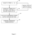
- FIG. 1 shows a flowchart of a method for detecting power output improvements according to a general embodiment of the invention.
- a setting X i is selected from a list of settings X 1 ,...,X N .
- a wind turbine is operated with the selected setting X i for a period of time t 1 , and the power output during t 1 is recorded.
- Steps 100 and 102 may be repeated until each of the N settings in the list have been tested a number of times c.
- a summarised power output (summarised over the c records) is calculated for each of the N settings.
- the summarised power outputs are compared to determine whether any setting X* results in a higher power output than the other settings in X 1 ,..., X N .
- a setting may be considered to result in a difference in power output when the difference between the summarised power output associated with setting X* and the summarised power output associated with a reference setting (or statistical estimate thereof) exceeds a threshold. In other words, once the difference exceeds the threshold the difference is considered to be "significant".
- a difference between summarised (e.g. accumulated or average of all cycles c for each setting X i ) power output that exceeds 0.1% may be considered significant.
- a difference exceeding 0.2, 0.5, 1, 1.5, 2 or 3% may be considered significant.
- a threshold may be predetermined, such as based on a known / quantified uncertainty around the measurements.
- the uncertainty around the measurements may be quantified empirically in a calibrating period prior to the normal use of the turbine (see below).
- a threshold may be dynamically adjusted based on the statistical uncertainty around measurements corresponding to the same conditions or the specific setting(s) concerned. For example, a threshold may be determined based on a number of standard deviations of the distribution of power outputs measured at the same wind speed (or the same wind speed bin) with the same settings.
- a measured or estimated wind speed during each t 1 may be used to determine if power output data collected over the testing periods for compared settings is comparable.
- data may only be compared if the wind speed (e.g. average wind speed) over the testing time period for compared settings is comparable.
- measurements may be aggregated overwind speed bins (see below).
- the power output may be monitored below the rated wind speed of a turbine, in particular in areas where comparatively large differences may be observed or expected.
- the power output may be monitored between 66% and 99% of the rated wind speed of the turbine.
- the power output may be monitored in the operating region where the rotor is operated at its rated speed and the power output is below the nominal power of the turbine.
- the power output may be monitored for wind speeds between 4 and 12 m/s, between 4 and 9 m/s, between 5.5 and 9 m/s, between 4 and 10.5 m/s, between 5.5 and 12 m/s, or between 5.5 and 10.5 m/s.
- the method may be used at wind speeds above the rated wind speed. For example, this may be used when it is advantageous to operate the wind turbine above the rated power in some periods or at some wind speed intervals.
- the power output may be monitored at wind speeds where the rotor functions at minimum speed, and/or at wind speeds where the rotor speed is between minimum speed and rated rotor speed, and/or at wind speeds where the rotor is operated at rated speed and the power output is below nominal power.
- the settings may be selected at step 100 in random order, in consecutive order, or according to a specified order. In some embodiments the order may vary between cycles.
- the "measured power output” or “power output” of a wind turbine may be a directly measured quantity (e.g. from a power output sensor), or may be indirectly obtained from another measured quantity.
- an improved regulation of pitch angle and / or rotor speed of a turbine may result in an increase of the lift versus drag force on the blades of the turbine, resulting in increased blade moment / torque and, hence, an increase in the cumulative blade moments and main shaft torque.
- any of these values may be used as an indication of a change in power output.
- blade load sensors in a turbine may be used to obtain a measurement of blade torque, and this may be used as an indication of a change in power output as different reference curves are used to operate the turbine.
- a "measured power output” or “power output” may be derived from any of the following measurements, alone or in combination: a main shaft torsion or torque; gearbox shaft torsion or torque; blade strain measurements (as an indication of blade torque) such as from strain gauges, optical fibres, blade load sensors, etc.; strain measurements on the blade bearings, blade bolts or hub (as an indication of increased torque); blade surface pressure measurements (from which lift force and pressure drag may be determined in one or more blade cross sections, based on which an indication of torque change can be obtained); blade tip mean deflection in edgewise direction; generator current; and tower lateral moment from e.g. load sensors on tower moments, tower top acceleration or tower top lateral deflections (as the change in main shaft torque is transferred at least partly to the tower top).
- any reference to a rotor speed may be used interchangeably to refer to a tip speed ratio or a generator speed.
- wind speed may refer to a measurement from a sensor, or a wind speed estimate indirectly obtained from other measurements, such as a power output measurement (or a power output estimate), and / or a rotor speed measurement.
- a wind speed estimate may be indirectly obtained from a power output value based on the knowledge of the expected power curve of the wind turbine.
- Wind speed estimates and ranges of wind speeds associated with a power output measurement may be derived from knowledge of the optimal power in different operating regions of a wind turbine, such as regions delimited by the minimum rotor speed, rated rotor speed and nominal power.
- rated or “nominal” power or rotor speed refer to the maximum allowable values for a wind turbine, which are a design parameter for any given wind turbine.
- rated wind speed corresponds to the wind speed at which the turbine reaches nominal power.
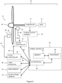
- FIG. 2 is a schematic representation of a typical wind turbine for use in the context of the disclosure.
- a wind turbine 10 comprises a rotor 12 coupled to a generator 14 providing power to the grid 16.
- a pitch controller 18 controls the pitch of the blades by providing a pitch control signal 20 to a pitch control mechanism in hub 22.
- the pitch controller 18 regulates the pitch of the blades based on a difference between a pitch position signal 24 measured by a pitch position sensor 26 and a pitch position command signal 28 provided by a turbine controller 30.
- the pitch controller 18 may determine a pitch control signal 20 based on a Proportional-Integral-Derivative (PID), Proportional-Integral (PI) or any other type of control loop feedback mechanism known to the person skilled in the art. Pitch controls that do not rely on feedback signals from the position sensor 26 (i.e. open loop controller) may alternatively be used. As the person skilled in the art would understand, the pitch controller 26 may be designed as a separate controller or may be comprised in a turbine controller 30 that directly provides a pitch control signal 20 to a pitch control mechanism. As the person skilled in the art would understand, although a single pitch controller 18, pitch command signal 28, position signal 24 and sensor 26 are described, multiple controllers, sensors and signals may be provided to control the pitch angle of individual blades.
- PID Proportional-Integral-Derivative
- PI Proportional-Integral
- any other type of control loop feedback mechanism known to the person skilled in the art. Pitch controls that do not rely on feedback signals
- a rotor speed controller 44 that controls the rotational speed of the rotor by providing a speed control signal 46 to a rotor speed control mechanism in rotor 12.
- a rotor speed controller 44 regulates rotor speed based on a difference between a rotor speed signal 48 from a rotor speed sensor 50 and a rotor speed command signal 52 provided by the turbine controller 30.
- a similar set up may be used for a yaw controller that regulates the orientation of the turbine in relation to the direction of the wind as determined by a wind direction sensor (not shown).
- Open loop controllers are also usable for both the rotor speed controller 44 and the yaw controller. As the person skilled in the art would understand, the precise implementation of all auxiliary controllers and sensors does not significantly impact the methods described in the present disclosure.
- the turbine controller 30 includes a processor 32, a memory 34, and an input / output interface 36.
- the processor 32 may include one or more processing circuits, and the memory 34 may comprise one or more memory devices, as known to the person skilled in the art.
- the input / output interface 36 operatively couples the processor 32 to other components such as sensors, controllers etc. The coupling may be wired or wireless, such as using a wireless network protocol as known in the art.
- the input / output interface may also couple the processor to a user interface 38.
- the user interface 38 may include input devices and controls, such as a keyboard, keypad, buttons, or any other device capable of accepting instructions from a user and transmitting it to the processor 32, as well as screens, displays or any other device capable of communicating information to a user.
- the turbine 10 may also be equipped with a series of sensors, such as a wind speed sensor 40, a power output sensor 42, a blade strain sensor 54 etc. Additional sensors may be present, as known in the art, such as a temperature sensor, a rain sensor, a main shaft torsion sensor, blade surface pressure sensor, blade bearing, bolts or hub strain sensors, etc. (not shown).
- sensors such as a wind speed sensor 40, a power output sensor 42, a blade strain sensor 54 etc.
- Additional sensors may be present, as a temperature sensor, a rain sensor, a main shaft torsion sensor, blade surface pressure sensor, blade bearing, bolts or hub strain sensors, etc. (not shown).
- the controller 30 may determine a pitch command signal 28 for the pitch controller 18 and / or a rotor speed command signal 52 for the rotor speed controller 44, based on a wind speed measurement or estimate (e.g. a signal from the wind speed sensor 40 or a wind speed estimate calculated based on signals from e.g. the power output sensor 42, rotor speed sensor 50 and / or pitch angle sensor 26), and a control method for optimal power output regulation as explained above, stored in the memory 34 of the controller.
- a controller 30 may request data from the various sensors, and in particular the power output sensor 42 and wind speed sensor 40, and store this data in the memory 34.
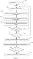
- Figure 3 displays a flowchart of a method of determining power output, e.g. potential AEP improvements according to embodiments of the invention.
- a user inputs in the controller 30 a series of parameters including the settings to be tested (i.e. a total of N settings X 1 to X N , where N ⁇ 2 including any default setting and comparative settings), and optionally a time period t 1 , a time period t 2 and/or a time period t 3 .
- cycle c is in progress and the controller selects setting X i from the list of N settings.
- the controller 30 may execute instructions to operate the turbine 10 with setting X i for a period of time t 2 , in order to allow the turbine operation to reach equilibrium. Measurements of power production acquired during optional step 303 may not be recorded.
- the controller 30 executes instructions to operate the turbine 10 with setting X i for a time period of t 1 . This may include the controller 30 using a particular method or parameter stored in the memory 34 to control the operation of the turbine 10 (i.e. causing the processor 32 to use a different regulation model / parameters to compute a control signal for e.g. the pitch controller 18, the rotor speed controller 44 or the yaw controller).
- the controller 30 records in memory 34 the power production signal provided by the power output sensor 42 or indirectly obtained from a signal provided by any sensor from which an indication of power output can be calculated (see above) over the period of operation of the turbine 10 at setting X i for cycle c.
- the signal may comprise e.g. a continuous or almost continuous signal of instantaneous power production over t 1 or an accumulated power production (over t 1 or since recording, from which a signal over t 1 can be trivially derived based on a measurement at the start of t 1 ).
- Any metric derived from the above signal may also be used, such as e.g. any statistical estimate of the instantaneous power production over t 1 (e.g. mean, median, etc.).
- Data from additional sensors such as data from the pitch position sensor 26, the rotor speed sensor 50, or the wind speed sensor 40 etc. may also be recorded at step 306.
- the controller may instead, or in addition to recording a signal from a power output sensor, calculate an estimated power output based on data from other sensors such as a blade strain sensor 54 and/or a wind speed estimate based e.g. on the power output, pitch and rotor speed signals.
- the period of time t 1 may not necessarily be the same for every cycle of the method and / or for every setting X i .
- the period of time t 1 may be a minimum period of time.
- power output values may be normalised.
- the controller 30 checks whether all settings X 1 to X N have been used in cycle c . In the negative, the controller repeats steps 302 to 308 for a new setting X. In the affirmative, the controller 30 updates the cycle counter to c+1 and repeats steps 302 to 308 for all N settings in the list of settings. As stated above (step 303), the controller 30 may optionally implement a break of t 2 seconds between consecutive settings, during which the power output measurements are not taken into account, such as to allow for the settings to be changed, the new conditions (power production in response to new setting, readings of sensors etc.) to stabilise, etc. Optionally, the controller 30 may additionally implement a break of t 3 seconds between consecutive cycles, i.e. at step 310 in Figure 3 .
- the controller checks whether a sufficient number of cycles c have been completed (i.e. the number of cycles has reached or exceeded a threshold c th ).
- a user may be able to specify, instead of an amount of cycles, an amount of time since the beginning of the process (which can be converted into a number of cycles based on the parameters t 1 and optionally t 2 and/or t 3 ).
- the minimum number of cycles may be determined dynamically based on a minimum number of data points, a statistical metric of variability, etc. (see further below).
- a user may be able to manually interrupt the process at any point (i.e. at any cycle).
- the controller accumulates the power values stored at step 306 over all c cycles separately for each setting X 1 to X N .
- the controller may perform step 312 at the end of each day, or after a given number of cycles, then the controller may resume measurement for another period or set of cycles (i.e. the cycle counter may be reset and the method may start again from step 302).
- other metrics derived from the cumulated data may be used, such as e.g. the average of the power values.
- the average of power values is directly proportional to the sum of the power production values, with an identical proportionality factor for all settings, thereby making the comparison of averages equivalent to the comparison of accumulated power.
- the controller 30 may take the additional data from sensors that may have been recorded at step 306 to separate the data into different sets. For example, the controller 30 may classify the data according to a wind speed value (measured or estimated from other signals) recorded at step 306. Other criteria to include or exclude individual data points or groups of data points may also be specified, e.g. by a user, or built into the instructions executed by the controller, such as e.g. a criterion on data outliers etc. In some embodiments, a cycle in which any of the measurements falls outside of a predetermined region (e.g. in terms of power output - measured or estimated, rotor speed, measured or estimated wind speed) may be disregarded. In some embodiments, mean power measurements that differ by more than a defined threshold from other measurements for the same setting in the same estimated wind speed region may be disregarded, for example in order to exclude outliers that may be the result of unknown errors.
- a wind speed value measured or estimated from other signals
- the controller 30 compares the accumulated (and optionally filtered or classified) values obtained for the different settings. For example, the controller 30 may evaluate the difference in accumulated power output between a test setting and a reference or default setting. Optionally, the controller 30 may also decide at step 316 whether any measured / detected difference is "significant". At step 318 the controller may optionally operate the turbine 10 on a new setting that was found at step 316 to result in a significant power production improvement over other tested settings. Settings may be compared over a particular instance of the method or any setting X* may be compared to previously tested settings, e.g. obtained with comparable parameters or normalised appropriately (such as e.g. to account for differences in t 1 used, etc.).
- some steps of the above method may be performed by an external controller, which exchanges information with the turbine controller 30.
- the controller may instead or in addition to recording data in memory 34 at step 306, communicate the data to an external computing device or a user via the input / output interface 36.
- any of steps 310, 312, 314 and 316 may be performed by a separate computing device (or a user, for steps 310 and 316).
- the length of the time period t 1 may be such that the ambient conditions can reasonably be expected to be stable over the time period (and so should the power output), such that a large number of measurement periods can be obtained over a short period of time, and/or such that the length of time is sufficient to obtain a representative measurement.
- these assumptions may be verified before using one or more data points, such as using the power output data and optionally additional data from sensors recorded at step 306.
- data points that do not comply with these assumptions may be filtered out
- t 1 is between 5 seconds and a minute, between 5s and 2 minutes, or between 5s and 5 minutes.
- t 1 is about 5 seconds, about 10 seconds, about 15 seconds, about 20 seconds, about 25s, about 30s, about 35s, about 40s, about 45s, about 50s, about 55s, about a minute, about 75s, about 90s, or about 2 minutes. In some embodiments, t 1 is below 10 minutes, below 5 minutes, below 2 minutes, below a minute.
- the length of the time period t 2 may be set to the shortest period allowing for a change of settings and e.g. stabilisation of operating parameters following the change.
- t 2 may depend on the settings to be tested.
- t 1 may be shorter than t 2 .
- t 2 may be about 5 seconds, about 10 seconds, about 15 s, about 20s, about 25s, about 30s.
- t 2 may be under a minute.
- t 1 and/or t 2 may be automatically set to default values.
- t 1 and/or t 2 may be specified by a user.
- t 3 may be between t 2 and 3 ⁇ t 2 .
- the data may be separated based on the wind speed associated with each period t 1 with setting x i in cycle c .
- the wind speed may be measured (using a wind speed sensor 40) or estimated.
- the wind speed estimate may be calculated, e.g. based on the expected relationship between power output and wind speed for the turbine.
- the data may be separated based on bins along the wind speed axis. In some embodiments, bins of 0.1 m/s, 0.5 m/s, 1 m/s, 1.5 m/s or 2 m/s width may be used.
- the width of the bins represents a trade-off between the precision of estimates obtained and the accuracy of estimates due to the availability of measurement points falling within a bin.
- the width of the bins may vary along the range of wind speeds observed for a particular turbine at a particular site, such that e.g. bins may be narrower around wind speeds that are frequently observed.
- bin width may depend on the density of measurements along the wind speed axis, i.e. bins may be narrower in regions of more frequent wind speeds. Wind speed bins that correspond to areas where large differences are expected may also be narrower as fewer measurements may then be required to be able to conclude that a difference in power output is "significant".
- the appropriate width of bins may be determined prior to putting the turbine into use (e.g. based on the expected behaviour of the turbine and / or expected environmental conditions on a site), or may be adjusted in use.
- the appropriate width may be adapted through a learning / adaptive process throughout use, or may be changed depending on the time of the year and corresponding changes in expected environmental conditions, such as depending on the frequency of wind speeds falling within each bin.
- the data may be binned at step 306, i.e. the controller may only record a wind bin rather than a wind speed value.
- the data may be binned at step 312 based on wind speed measurements recorded at step 306.
- the data may not be separated into bins, and the cumulated power production over all wind speeds may be compared. In such embodiments, the power production during each period t 1 may be the only measurement required to perform the method of the disclosure.
- the decision at step 316 may be made based on data from all wind speeds. In some embodiments, the decision at step 316 may be made based on data from some wind speed bins. In some embodiments, the decision at step 316 may be based on data from bins where the (observed or expected) difference in power production between settings is the largest. In some embodiments, the decision at step 316 may be made using the power outputs associated with wind speeds in the wind speed bins in the region approaching the rated wind speed of the turbine. In some embodiments, the decision at step 316 may be based on the wind speed bins that are expected to be the most frequent at a particular site. In some embodiments, the wind speeds taken into account for the determination of performance improvement may be specified by a user. Such embodiments may be useful when some or all of the settings tested aim to produce a benefit in particular wind speed regions.
- any or all of t 1 , t 2 , t 3 , the number of cycles, and the significance threshold may be determined based on a calibration run.
- a calibration run may comprise running the method until the standard deviation of differences between accumulated power output per day falls below an acceptable threshold. The standard deviation in a calibration run is expected to decrease as the number of data points increases because with identical settings there should not be any difference in power output, and variations due to uneven environmental conditions and measurement error should average out.
- a calibration run may be performed prior to using the method to compare different settings.
- a calibration run may be performed simultaneously with a testing run, by including a series of identical control settings as part of X 1 ,.., X N . Data obtained for identical settings can e.g. be used to monitor the variability in the data as the number of cycles increases, and to identify a minimum difference in summarised power output that can reliably be identified.
- a reference setting is used to estimate the standard deviation of the mean power over c samples for the reference setting, and any setting associated with a mean power that differs from the reference mean power by more than 1.96 ⁇ SD is considered to be associated with a change in performance (where SD is the standard deviation of the n mean power measurements for the reference setting divided by the square root of the number of measurements, where in the simplest case the number of measurements is equal to the number of cycles c).
- the method of the invention may be triggered automatically for a wind turbine.
- the controller may trigger the method automatically at regular intervals.
- the method may be triggered to test for new optimal settings whenever any changes may have occurred that might affect the optimal settings of a turbine.
- Such changes may comprise, e.g. normal wear of the turbine (e.g. blade leading edge erosion), seasonal changes (i.e. changes in wind conditions, precipitations, average temperatures, length of day / night), etc.
- the controller may automatically launch the method following an event (e.g. heavy rain, sudden change in temperature, etc.). In other embodiments the method may be triggered manually.
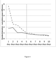
- Figure 4 illustrates an example of two calibration runs performed at a one month interval on the same turbine.
- Each run consisted of six identical controller settings tested over 10 seconds in each cycle. The average power output per minute was calculated for each of these and accumulated over each day. Differences between these cumulated values for each "pair of settings" were computed and standard deviations calculated after each day. Because the data relates to a situation where there is no difference in the controller settings, the difference in power production is expected to move to 0 over time. However, random noise in the measurements, as well as differences in the exact conditions between each period mean that although the expected value is zero, the measured difference will be distributed around the expected value with a certain spread, where this spread decreases as data accumulates.
- Figure 5 illustrates an example of the use of the method of the invention to detect settings associated with improved performance.
- a wind turbine controller was configured to operate with five different curves of regulation of the pitch angle as a function of the tip speed ratio.
- “Toggle 1" corresponds to the curve initially used
- “Toggle 2" to “Toggle 5" correspond to modified curves with a 0.5 degree pitch offset for some tip speed ratios.
- the controller shifted operation from one curve to a different one every 20 seconds.
- the power production was recorded during the last 10 seconds of each 20 seconds interval and averaged, and the data was binned based on wind speed.
- the mean power for each bin for each setting was then calculated at different intervals while the method was repeated (corresponding to increasing numbers of samples based on which the mean power is estimated), and plotted.
Claims (10)
- Dispositif de commande (30) pour une éolienne (10) comprenant :un processeur (32) ;une interface d'entrée/sortie (36) ; etune mémoire (34) incluant des instructions qui, lorsqu'elles sont exécutées par le processeur (32), amènent le processeur (32) à :i) sélectionner un réglage xi parmi une liste de réglages X1, ..., XN ;ii) faire fonctionner la turbine (10) selon un réglage X pendant une durée t1 ;iii) enregistrer un signal de sortie de puissance sur t1 ;iv) répéter les étapes i) à iii) pour un autre réglage dans X1, ..., XN jusqu'à ce que tous les N réglages aient été utilisés ;v) répéter les étapes i) à iv) pour un nombre de cycles c ;vi) calculer une sortie de puissance résumée pour chaque réglage sur tous les cycles, dans lequel une sortie de puissance résumée est une valeur de sortie de puissance cumulée ou une valeur de sortie de puissance moyenne ;vii) comparer les sorties de puissance résumées dans les réglages et déterminer si un quelconque réglage X∗ a pour résultat une sortie de puissance qui est supérieure, d'un seuil différentiel, à d'autres réglages testés ;dans lequel le processeur (32) exécute également des instructions pour enregistrer des données indiquant la vitesse du vent à partir d'un ou plusieurs capteurs (40, 42, 54) pour chaque période t1, et dans lequel les données de sortie de puissance sont séparées en cases de vitesse du vent selon la vitesse du vent mesurée ou estimée durant chaque t1, et la sortie de puissance résumée chiffrée à l'étape vi) est chiffrée séparément pour chaque case de vitesse du vent.
- Dispositif de commande (30) selon la revendication 1, dans lequel le processeur (32) exécute de plus des instructions pour faire fonctionner la turbine (10) avec un réglage X∗ trouvé à l'étape vii) pour avoir pour résultat une sortie de puissance supérieure.
- Dispositif de commande (30) selon une quelconque revendication précédente, dans lequel un passage d'étalonnage est réalisé pour déterminer un ou plusieurs parmi : un nombre de cycles c, la durée t1, la durée t2, le nombre de réglages testés N, le seuil différentiel pour qu'une sortie de puissance résumée soit considérée comme supérieure à une autre.
- Dispositif de commande (30) selon la revendication 3, dans lequel le passage d'étalonnage est réalisé en même temps que le passage de test, en répétant les étapes i) à iii) pour le même réglage en plus des réglages de test.
- Dispositif de commande (30) selon une quelconque revendication précédente, dans lequel les sorties de puissance résumées sont comparées à l'étape vii) sur une plage de vitesses du vent, de préférence en dessous de la vitesse du vent nominale de l'éolienne (10).
- Dispositif de commande (30) selon une quelconque revendication précédente, dans lequel la sortie de puissance comprend des mesures à partir d'un capteur de sortie de puissance et/ou des valeurs obtenues indirectement à partir d'autres quantités mesurées, de préférence dans lequel les autres mesures comprennent l'un quelconque de mesures de torsion d'arbre principal, de mesures de couple d'arbre principal, de mesures de torsion d'arbre de boîte d'engrenages, de mesures d'effort de pale, de mesures de charge de pale, de mesures d'effort sur les paliers de pale, de mesures d'effort sur les boulons de pale, de mesures d'effort sur le moyeu, de mesures de pression de surface de pale, d'une déviation moyenne de bout de pale dans la direction longitudinale du profil, d'un courant de générateur, d'une puissance de transformateur, d'un courant de transformateur, et/ou d'un moment latéral de tour.
- Dispositif de commande (30) selon une quelconque revendication précédente, dans lequel la durée t1 est entre 5 secondes et 5 minutes, ou la durée t1 + t2 est entre 5 secondes et 5 minutes.
- Procédé d'identification d'améliorations de production d'énergie dans une éolienne (10), le procédé comprenant :i) une sélection d'un réglage xi parmi une liste de réglages X1, ..., XN ;ii) un fonctionnement de la turbine (10) selon un réglage Xi pendant une durée t1;iii) un enregistrement d'un signal de sortie de puissance sur t1 ;iv) une répétition des étapes i à iii pour un autre réglage dans X1, ..., XN jusqu'à ce que tous les N réglages aient été utilisés ;v) une répétition des étapes i à iv pour un nombre de cycles c ;vi) un calcul d'une sortie de puissance résumée pour chaque réglage sur tous les cycles ;vii) une comparaison des sorties de puissance résumées dans les réglages et le fait de déterminer si un quelconque réglage X∗ a pour résultat une sortie de puissance qui est supérieure, d'un seuil différentiel, à d'autres réglages testés ;dans lequel le procédé comprend en outre un enregistrement de données indiquant la vitesse du vent pour chaque période t1, une séparation des données de sortie de puissance en cases de vitesse du vent selon la vitesse du vent mesurée ou estimée durant chaque t1, et un chiffrage de la sortie de puissance résumée chiffrée à l'étape vi) séparément pour chaque case de vitesse du vent.
- Programme d'ordinateur pour un dispositif de commande (30) d'une éolienne (10), qui lorsqu'il est exécuté par le dispositif de commande (30) amène le dispositif de commande (30) à réaliser le procédé selon la revendication 8.
- Eolienne (10) comprenant le dispositif de commande (30) selon l'une quelconque des revendications 1 à 7.
Applications Claiming Priority (2)
| Application Number | Priority Date | Filing Date | Title |
|---|---|---|---|
| DKPA201670406 | 2016-06-07 | ||
| PCT/DK2017/050185 WO2017211368A1 (fr) | 2016-06-07 | 2017-06-06 | Commande adaptative d'éolienne par détection d'un changement de rendement |
Publications (2)
| Publication Number | Publication Date |
|---|---|
| EP3464891A1 EP3464891A1 (fr) | 2019-04-10 |
| EP3464891B1 true EP3464891B1 (fr) | 2022-01-19 |
Family
ID=59067438
Family Applications (1)
| Application Number | Title | Priority Date | Filing Date |
|---|---|---|---|
| EP17730371.6A Active EP3464891B1 (fr) | 2016-06-07 | 2017-06-06 | Commande adaptative d'éolienne par détection d'un changement de rendement |
Country Status (3)
| Country | Link |
|---|---|
| US (2) | US10641244B2 (fr) |
| EP (1) | EP3464891B1 (fr) |
| WO (1) | WO2017211368A1 (fr) |
Families Citing this family (6)
| Publication number | Priority date | Publication date | Assignee | Title |
|---|---|---|---|---|
| WO2017211368A1 (fr) | 2016-06-07 | 2017-12-14 | Vestas Wind Systems A/S | Commande adaptative d'éolienne par détection d'un changement de rendement |
| DE102018112825A1 (de) * | 2018-05-29 | 2019-12-05 | fos4X GmbH | Sensoranordnung für eine Windkraftanlage |
| US11060504B1 (en) | 2020-02-07 | 2021-07-13 | General Electric Company | Systems and methods for continuous machine learning based control of wind turbines |
| US11231012B1 (en) | 2020-09-22 | 2022-01-25 | General Electric Renovables Espana, S.L. | Systems and methods for controlling a wind turbine |
| US11649804B2 (en) | 2021-06-07 | 2023-05-16 | General Electric Renovables Espana, S.L. | Systems and methods for controlling a wind turbine |
| CN113757041A (zh) * | 2021-08-12 | 2021-12-07 | 太原重工股份有限公司 | 一种风力发电机组风向数据的智能校准方法及系统 |
Family Cites Families (33)
| Publication number | Priority date | Publication date | Assignee | Title |
|---|---|---|---|---|
| US20020084655A1 (en) * | 2000-12-29 | 2002-07-04 | Abb Research Ltd. | System, method and computer program product for enhancing commercial value of electrical power produced from a renewable energy power production facility |
| US10135253B2 (en) * | 2000-12-29 | 2018-11-20 | Abb Schweiz Ag | System, method and computer program product for enhancing commercial value of electrical power produced from a renewable energy power production facility |
| US20070124025A1 (en) * | 2005-11-29 | 2007-05-31 | General Electric Company | Windpark turbine control system and method for wind condition estimation and performance optimization |
| EP2035899A1 (fr) | 2006-04-26 | 2009-03-18 | Alliance for Sustainable Energy, LLC | Commande de pas adaptative pour turbines eoliennes a vitesse variable |
| US7560823B2 (en) | 2006-06-30 | 2009-07-14 | General Electric Company | Wind energy system and method of operation thereof |
| EP1911968A1 (fr) | 2006-10-10 | 2008-04-16 | Ecotecnia Energias Renovables S.L. | Système de réglage pour une turbine éolienne et procédé de réglage |
| US7883317B2 (en) | 2007-02-02 | 2011-02-08 | General Electric Company | Method for optimizing the operation of a wind turbine |
| US20090099702A1 (en) * | 2007-10-16 | 2009-04-16 | General Electric Company | System and method for optimizing wake interaction between wind turbines |
| EP2175129A1 (fr) | 2008-10-10 | 2010-04-14 | Siemens Aktiengesellschaft | Ajustement adaptatif de l'angle de pas de pale d'une éolienne |
| WO2010057737A2 (fr) | 2008-11-18 | 2010-05-27 | Vestas Wind Systems A/S | Procédé de régulation du fonctionnement d’une éolienne |
| US9328718B2 (en) * | 2009-06-30 | 2016-05-03 | Vestas Wind Systems A/S | Method of calculating an electrical output of a wind power plant |
| GB2476316B (en) | 2009-12-21 | 2014-07-16 | Vestas Wind Sys As | A wind turbine having a control method and controller for predictive control of a wind turbine generator |
| US7987067B2 (en) | 2010-03-26 | 2011-07-26 | General Electric Company | Method and apparatus for optimizing wind turbine operation |
| DE102010056456A1 (de) * | 2010-12-29 | 2012-06-21 | Repower Systems Ag | Windpark und Verfahren zum Betreiben eines Windparks |
| WO2012138235A2 (fr) * | 2011-04-08 | 2012-10-11 | Auckland Uniservices Limited | Gestion d'énergie côté demande locale pour réseau de service d'électricité |
| US20120271593A1 (en) * | 2011-04-21 | 2012-10-25 | Honeywell International Inc. | Monitoring wind turbine performance |
| EP2559894A1 (fr) | 2011-08-18 | 2013-02-20 | Siemens Aktiengesellschaft | Procédé d'ajustement de l'angle d'inclinaison des pales d'une éolienne |
| US20120112460A1 (en) | 2011-12-22 | 2012-05-10 | Vestas Wind Systems A/S | Probing power optimization for wind farms |
| EP2679813B2 (fr) | 2012-06-28 | 2019-11-20 | Siemens Gamesa Renewable Energy A/S | Système et procédés pour améliorer la performance d'un système d'échantillonnage à base de semi-conducteur |
| US10992185B2 (en) * | 2012-07-06 | 2021-04-27 | Energous Corporation | Systems and methods of using electromagnetic waves to wirelessly deliver power to game controllers |
| WO2014038966A1 (fr) * | 2012-09-06 | 2014-03-13 | Auckland Uniservices Limited | Gestion de puissance côté demande locale pour réseaux de service public électriques |
| KR101425016B1 (ko) * | 2012-09-18 | 2014-08-01 | 한국전력공사 | 풍력터빈의 파워커브 모니터링을 위한 파워커브 리미트 자동 산출 방법 |
| EP3077662B1 (fr) * | 2013-11-28 | 2018-10-03 | Vestas Wind Systems A/S | Supervision basique de réseau d'un parc éolien |
| US9551322B2 (en) * | 2014-04-29 | 2017-01-24 | General Electric Company | Systems and methods for optimizing operation of a wind farm |
| CA2965364C (fr) * | 2014-11-11 | 2021-06-08 | Protonex Technology Corporation | Module de commande pour reseau de puissance en courant continu |
| US10487804B2 (en) * | 2015-03-11 | 2019-11-26 | General Electric Company | Systems and methods for validating wind farm performance improvements |
| US10385829B2 (en) * | 2016-05-11 | 2019-08-20 | General Electric Company | System and method for validating optimization of a wind farm |
| WO2017211368A1 (fr) | 2016-06-07 | 2017-12-14 | Vestas Wind Systems A/S | Commande adaptative d'éolienne par détection d'un changement de rendement |
| US10483803B2 (en) | 2016-08-23 | 2019-11-19 | Wits Co., Ltd. | Wireless power transmitter and method for wirelessly transmitting power |
| WO2018171852A1 (fr) * | 2017-03-21 | 2018-09-27 | Vestas Wind Systems A/S | Système et procédé permettant de gérer une vibration de torsion d'une tour éolienne |
| US11043815B2 (en) * | 2017-07-28 | 2021-06-22 | The Florida State University Research Foundation, Inc. | Optimal control technology for distributed energy resources |
| WO2019141331A1 (fr) * | 2018-01-22 | 2019-07-25 | Vestas Wind Systems A/S | Procédé de commande d'un objet aéroporté couplé à une éolienne |
| US10815972B2 (en) * | 2019-03-22 | 2020-10-27 | General Electric Company | System and method for assessing and validating wind turbine and wind farm performance |
-
2017
- 2017-06-06 WO PCT/DK2017/050185 patent/WO2017211368A1/fr unknown
- 2017-06-06 EP EP17730371.6A patent/EP3464891B1/fr active Active
- 2017-06-06 US US16/306,850 patent/US10641244B2/en active Active
-
2020
- 2020-05-01 US US16/865,113 patent/US10982653B2/en active Active
Also Published As
| Publication number | Publication date |
|---|---|
| EP3464891A1 (fr) | 2019-04-10 |
| US20190170119A1 (en) | 2019-06-06 |
| US10982653B2 (en) | 2021-04-20 |
| US20200263667A1 (en) | 2020-08-20 |
| WO2017211368A1 (fr) | 2017-12-14 |
| US10641244B2 (en) | 2020-05-05 |
Similar Documents
| Publication | Publication Date | Title |
|---|---|---|
| EP3464891B1 (fr) | Commande adaptative d'éolienne par détection d'un changement de rendement | |
| WO2017211367A1 (fr) | Commande adaptative d'une turbine éolienne par détection d'un changement de performances | |
| US10683844B2 (en) | Control of a wind turbine taking fatigue measure into account | |
| US9790921B2 (en) | Method and system for adjusting a power parameter of a wind turbine | |
| CN107110121B (zh) | 对风力涡轮机构造的确定 | |
| US11181096B2 (en) | Control method for a wind turbine | |
| DK1988284T3 (en) | Method of operating a wind turbine and wind turbine | |
| EP2302206A1 (fr) | Sélection de mesure de réduction de charge pour le fonctionnement d'une machine de génération d'énergie | |
| CN108474348B (zh) | 用于风力涡轮机的控制方法 | |
| DK2878809T3 (en) | Methods of operating a wind turbine, wind turbines and wind farms | |
| EP2302207A1 (fr) | Contrôle de charge d'une machine de génération d'énergie basé sur la durée de vie de fatigue consommée et temps réel des opérations d'un composant structurel | |
| EP3642481B1 (fr) | Procédé de détermination de récurrence de charge dans le sens de la traînée de pale d'éolienne | |
| WO2017108044A1 (fr) | Commande de turbines éoliennes en fonction d'estimations de fiabilité | |
| US20150050145A1 (en) | Method for operating a wind turbine, and a corresponding wind turbine | |
| US20220186714A1 (en) | Method for detecting an accretion of ice on a wind turbine | |
| US11168664B2 (en) | Control method for a wind turbine | |
| DK2923080T3 (en) | PROCEDURE FOR OPERATING A WIND ENERGY INSTALLATION AND WIND ENERGY INSTALLATION | |
| DK201570721A1 (en) | CONTROL OF A WIND TURBINE TAKING FATIGUE MEASURE INTO ACCOUNT | |
| CN114303012A (zh) | 低于额定风速时控制风力涡轮机的功率输出 | |
| CN114738206A (zh) | 风力发电机叶片的覆冰运行控制方法、装置及风力发电机 | |
| CN112943528A (zh) | 风力发电机组的控制方法和装置 |
Legal Events
| Date | Code | Title | Description |
|---|---|---|---|
| STAA | Information on the status of an ep patent application or granted ep patent |
Free format text: STATUS: UNKNOWN |
|
| STAA | Information on the status of an ep patent application or granted ep patent |
Free format text: STATUS: THE INTERNATIONAL PUBLICATION HAS BEEN MADE |
|
| PUAI | Public reference made under article 153(3) epc to a published international application that has entered the european phase |
Free format text: ORIGINAL CODE: 0009012 |
|
| STAA | Information on the status of an ep patent application or granted ep patent |
Free format text: STATUS: REQUEST FOR EXAMINATION WAS MADE |
|
| 17P | Request for examination filed |
Effective date: 20181203 |
|
| AK | Designated contracting states |
Kind code of ref document: A1 Designated state(s): AL AT BE BG CH CY CZ DE DK EE ES FI FR GB GR HR HU IE IS IT LI LT LU LV MC MK MT NL NO PL PT RO RS SE SI SK SM TR |
|
| AX | Request for extension of the european patent |
Extension state: BA ME |
|
| DAV | Request for validation of the european patent (deleted) | ||
| DAX | Request for extension of the european patent (deleted) | ||
| STAA | Information on the status of an ep patent application or granted ep patent |
Free format text: STATUS: EXAMINATION IS IN PROGRESS |
|
| STAA | Information on the status of an ep patent application or granted ep patent |
Free format text: STATUS: EXAMINATION IS IN PROGRESS |
|
| 17Q | First examination report despatched |
Effective date: 20201216 |
|
| GRAP | Despatch of communication of intention to grant a patent |
Free format text: ORIGINAL CODE: EPIDOSNIGR1 |
|
| STAA | Information on the status of an ep patent application or granted ep patent |
Free format text: STATUS: GRANT OF PATENT IS INTENDED |
|
| INTG | Intention to grant announced |
Effective date: 20211021 |
|
| GRAS | Grant fee paid |
Free format text: ORIGINAL CODE: EPIDOSNIGR3 |
|
| GRAA | (expected) grant |
Free format text: ORIGINAL CODE: 0009210 |
|
| STAA | Information on the status of an ep patent application or granted ep patent |
Free format text: STATUS: THE PATENT HAS BEEN GRANTED |
|
| AK | Designated contracting states |
Kind code of ref document: B1 Designated state(s): AL AT BE BG CH CY CZ DE DK EE ES FI FR GB GR HR HU IE IS IT LI LT LU LV MC MK MT NL NO PL PT RO RS SE SI SK SM TR |
|
| REG | Reference to a national code |
Ref country code: GB Ref legal event code: FG4D |
|
| REG | Reference to a national code |
Ref country code: CH Ref legal event code: EP |
|
| REG | Reference to a national code |
Ref country code: DE Ref legal event code: R096 Ref document number: 602017052490 Country of ref document: DE |
|
| REG | Reference to a national code |
Ref country code: AT Ref legal event code: REF Ref document number: 1463930 Country of ref document: AT Kind code of ref document: T Effective date: 20220215 |
|
| REG | Reference to a national code |
Ref country code: IE Ref legal event code: FG4D |
|
| REG | Reference to a national code |
Ref country code: LT Ref legal event code: MG9D |
|
| REG | Reference to a national code |
Ref country code: NL Ref legal event code: MP Effective date: 20220119 |
|
| REG | Reference to a national code |
Ref country code: AT Ref legal event code: MK05 Ref document number: 1463930 Country of ref document: AT Kind code of ref document: T Effective date: 20220119 |
|
| PG25 | Lapsed in a contracting state [announced via postgrant information from national office to epo] |
Ref country code: NL Free format text: LAPSE BECAUSE OF FAILURE TO SUBMIT A TRANSLATION OF THE DESCRIPTION OR TO PAY THE FEE WITHIN THE PRESCRIBED TIME-LIMIT Effective date: 20220119 |
|
| PG25 | Lapsed in a contracting state [announced via postgrant information from national office to epo] |
Ref country code: SE Free format text: LAPSE BECAUSE OF FAILURE TO SUBMIT A TRANSLATION OF THE DESCRIPTION OR TO PAY THE FEE WITHIN THE PRESCRIBED TIME-LIMIT Effective date: 20220119 Ref country code: RS Free format text: LAPSE BECAUSE OF FAILURE TO SUBMIT A TRANSLATION OF THE DESCRIPTION OR TO PAY THE FEE WITHIN THE PRESCRIBED TIME-LIMIT Effective date: 20220119 Ref country code: PT Free format text: LAPSE BECAUSE OF FAILURE TO SUBMIT A TRANSLATION OF THE DESCRIPTION OR TO PAY THE FEE WITHIN THE PRESCRIBED TIME-LIMIT Effective date: 20220519 Ref country code: NO Free format text: LAPSE BECAUSE OF FAILURE TO SUBMIT A TRANSLATION OF THE DESCRIPTION OR TO PAY THE FEE WITHIN THE PRESCRIBED TIME-LIMIT Effective date: 20220419 Ref country code: LT Free format text: LAPSE BECAUSE OF FAILURE TO SUBMIT A TRANSLATION OF THE DESCRIPTION OR TO PAY THE FEE WITHIN THE PRESCRIBED TIME-LIMIT Effective date: 20220119 Ref country code: HR Free format text: LAPSE BECAUSE OF FAILURE TO SUBMIT A TRANSLATION OF THE DESCRIPTION OR TO PAY THE FEE WITHIN THE PRESCRIBED TIME-LIMIT Effective date: 20220119 Ref country code: ES Free format text: LAPSE BECAUSE OF FAILURE TO SUBMIT A TRANSLATION OF THE DESCRIPTION OR TO PAY THE FEE WITHIN THE PRESCRIBED TIME-LIMIT Effective date: 20220119 Ref country code: BG Free format text: LAPSE BECAUSE OF FAILURE TO SUBMIT A TRANSLATION OF THE DESCRIPTION OR TO PAY THE FEE WITHIN THE PRESCRIBED TIME-LIMIT Effective date: 20220419 |
|
| PG25 | Lapsed in a contracting state [announced via postgrant information from national office to epo] |
Ref country code: PL Free format text: LAPSE BECAUSE OF FAILURE TO SUBMIT A TRANSLATION OF THE DESCRIPTION OR TO PAY THE FEE WITHIN THE PRESCRIBED TIME-LIMIT Effective date: 20220119 Ref country code: LV Free format text: LAPSE BECAUSE OF FAILURE TO SUBMIT A TRANSLATION OF THE DESCRIPTION OR TO PAY THE FEE WITHIN THE PRESCRIBED TIME-LIMIT Effective date: 20220119 Ref country code: GR Free format text: LAPSE BECAUSE OF FAILURE TO SUBMIT A TRANSLATION OF THE DESCRIPTION OR TO PAY THE FEE WITHIN THE PRESCRIBED TIME-LIMIT Effective date: 20220420 Ref country code: FI Free format text: LAPSE BECAUSE OF FAILURE TO SUBMIT A TRANSLATION OF THE DESCRIPTION OR TO PAY THE FEE WITHIN THE PRESCRIBED TIME-LIMIT Effective date: 20220119 Ref country code: AT Free format text: LAPSE BECAUSE OF FAILURE TO SUBMIT A TRANSLATION OF THE DESCRIPTION OR TO PAY THE FEE WITHIN THE PRESCRIBED TIME-LIMIT Effective date: 20220119 |
|
| PG25 | Lapsed in a contracting state [announced via postgrant information from national office to epo] |
Ref country code: IS Free format text: LAPSE BECAUSE OF FAILURE TO SUBMIT A TRANSLATION OF THE DESCRIPTION OR TO PAY THE FEE WITHIN THE PRESCRIBED TIME-LIMIT Effective date: 20220519 |
|
| REG | Reference to a national code |
Ref country code: DE Ref legal event code: R097 Ref document number: 602017052490 Country of ref document: DE |
|
| PG25 | Lapsed in a contracting state [announced via postgrant information from national office to epo] |
Ref country code: SM Free format text: LAPSE BECAUSE OF FAILURE TO SUBMIT A TRANSLATION OF THE DESCRIPTION OR TO PAY THE FEE WITHIN THE PRESCRIBED TIME-LIMIT Effective date: 20220119 Ref country code: SK Free format text: LAPSE BECAUSE OF FAILURE TO SUBMIT A TRANSLATION OF THE DESCRIPTION OR TO PAY THE FEE WITHIN THE PRESCRIBED TIME-LIMIT Effective date: 20220119 Ref country code: RO Free format text: LAPSE BECAUSE OF FAILURE TO SUBMIT A TRANSLATION OF THE DESCRIPTION OR TO PAY THE FEE WITHIN THE PRESCRIBED TIME-LIMIT Effective date: 20220119 Ref country code: EE Free format text: LAPSE BECAUSE OF FAILURE TO SUBMIT A TRANSLATION OF THE DESCRIPTION OR TO PAY THE FEE WITHIN THE PRESCRIBED TIME-LIMIT Effective date: 20220119 Ref country code: DK Free format text: LAPSE BECAUSE OF FAILURE TO SUBMIT A TRANSLATION OF THE DESCRIPTION OR TO PAY THE FEE WITHIN THE PRESCRIBED TIME-LIMIT Effective date: 20220119 Ref country code: CZ Free format text: LAPSE BECAUSE OF FAILURE TO SUBMIT A TRANSLATION OF THE DESCRIPTION OR TO PAY THE FEE WITHIN THE PRESCRIBED TIME-LIMIT Effective date: 20220119 |
|
| PLBE | No opposition filed within time limit |
Free format text: ORIGINAL CODE: 0009261 |
|
| STAA | Information on the status of an ep patent application or granted ep patent |
Free format text: STATUS: NO OPPOSITION FILED WITHIN TIME LIMIT |
|
| PG25 | Lapsed in a contracting state [announced via postgrant information from national office to epo] |
Ref country code: AL Free format text: LAPSE BECAUSE OF FAILURE TO SUBMIT A TRANSLATION OF THE DESCRIPTION OR TO PAY THE FEE WITHIN THE PRESCRIBED TIME-LIMIT Effective date: 20220119 |
|
| 26N | No opposition filed |
Effective date: 20221020 |
|
| PG25 | Lapsed in a contracting state [announced via postgrant information from national office to epo] |
Ref country code: MC Free format text: LAPSE BECAUSE OF FAILURE TO SUBMIT A TRANSLATION OF THE DESCRIPTION OR TO PAY THE FEE WITHIN THE PRESCRIBED TIME-LIMIT Effective date: 20220119 |
|
| REG | Reference to a national code |
Ref country code: CH Ref legal event code: PL |
|
| REG | Reference to a national code |
Ref country code: BE Ref legal event code: MM Effective date: 20220630 |
|
| PG25 | Lapsed in a contracting state [announced via postgrant information from national office to epo] |
Ref country code: SI Free format text: LAPSE BECAUSE OF FAILURE TO SUBMIT A TRANSLATION OF THE DESCRIPTION OR TO PAY THE FEE WITHIN THE PRESCRIBED TIME-LIMIT Effective date: 20220119 |
|
| PG25 | Lapsed in a contracting state [announced via postgrant information from national office to epo] |
Ref country code: LU Free format text: LAPSE BECAUSE OF NON-PAYMENT OF DUE FEES Effective date: 20220606 Ref country code: LI Free format text: LAPSE BECAUSE OF NON-PAYMENT OF DUE FEES Effective date: 20220630 Ref country code: IE Free format text: LAPSE BECAUSE OF NON-PAYMENT OF DUE FEES Effective date: 20220606 Ref country code: CH Free format text: LAPSE BECAUSE OF NON-PAYMENT OF DUE FEES Effective date: 20220630 |
|
| PG25 | Lapsed in a contracting state [announced via postgrant information from national office to epo] |
Ref country code: BE Free format text: LAPSE BECAUSE OF NON-PAYMENT OF DUE FEES Effective date: 20220630 |
|
| P01 | Opt-out of the competence of the unified patent court (upc) registered |
Effective date: 20230521 |
|
| PG25 | Lapsed in a contracting state [announced via postgrant information from national office to epo] |
Ref country code: IT Free format text: LAPSE BECAUSE OF FAILURE TO SUBMIT A TRANSLATION OF THE DESCRIPTION OR TO PAY THE FEE WITHIN THE PRESCRIBED TIME-LIMIT Effective date: 20220119 |
|
| PGFP | Annual fee paid to national office [announced via postgrant information from national office to epo] |
Ref country code: FR Payment date: 20230622 Year of fee payment: 7 Ref country code: DE Payment date: 20230627 Year of fee payment: 7 |
|
| PGFP | Annual fee paid to national office [announced via postgrant information from national office to epo] |
Ref country code: GB Payment date: 20230620 Year of fee payment: 7 |
|
| PG25 | Lapsed in a contracting state [announced via postgrant information from national office to epo] |
Ref country code: HU Free format text: LAPSE BECAUSE OF FAILURE TO SUBMIT A TRANSLATION OF THE DESCRIPTION OR TO PAY THE FEE WITHIN THE PRESCRIBED TIME-LIMIT; INVALID AB INITIO Effective date: 20170606 |