EP3464124B1 - Transfer with contour checking - Google Patents
Transfer with contour checking Download PDFInfo
- Publication number
- EP3464124B1 EP3464124B1 EP17727826.4A EP17727826A EP3464124B1 EP 3464124 B1 EP3464124 B1 EP 3464124B1 EP 17727826 A EP17727826 A EP 17727826A EP 3464124 B1 EP3464124 B1 EP 3464124B1
- Authority
- EP
- European Patent Office
- Prior art keywords
- pallet
- rack
- pallet transfer
- pallets
- contour
- Prior art date
- Legal status (The legal status is an assumption and is not a legal conclusion. Google has not performed a legal analysis and makes no representation as to the accuracy of the status listed.)
- Active
Links
- 238000012546 transfer Methods 0.000 title claims description 59
- 230000003287 optical effect Effects 0.000 claims description 13
- 238000001514 detection method Methods 0.000 claims description 8
- 230000004888 barrier function Effects 0.000 claims description 7
- 238000009434 installation Methods 0.000 description 6
- 230000008901 benefit Effects 0.000 description 3
- 238000011161 development Methods 0.000 description 2
- 230000018109 developmental process Effects 0.000 description 2
- 238000000034 method Methods 0.000 description 2
- 230000008569 process Effects 0.000 description 2
- 238000012545 processing Methods 0.000 description 2
- 230000008859 change Effects 0.000 description 1
- 238000013461 design Methods 0.000 description 1
- 230000005484 gravity Effects 0.000 description 1
- 230000003760 hair shine Effects 0.000 description 1
- 230000012447 hatching Effects 0.000 description 1
- 238000007689 inspection Methods 0.000 description 1
- 230000004807 localization Effects 0.000 description 1
- 238000012986 modification Methods 0.000 description 1
- 230000004048 modification Effects 0.000 description 1
- 238000003909 pattern recognition Methods 0.000 description 1
- 238000000926 separation method Methods 0.000 description 1
Images


Classifications
-
- B—PERFORMING OPERATIONS; TRANSPORTING
- B65—CONVEYING; PACKING; STORING; HANDLING THIN OR FILAMENTARY MATERIAL
- B65G—TRANSPORT OR STORAGE DEVICES, e.g. CONVEYORS FOR LOADING OR TIPPING, SHOP CONVEYOR SYSTEMS OR PNEUMATIC TUBE CONVEYORS
- B65G1/00—Storing articles, individually or in orderly arrangement, in warehouses or magazines
- B65G1/02—Storage devices
- B65G1/04—Storage devices mechanical
- B65G1/0407—Storage devices mechanical using stacker cranes
-
- G—PHYSICS
- G01—MEASURING; TESTING
- G01B—MEASURING LENGTH, THICKNESS OR SIMILAR LINEAR DIMENSIONS; MEASURING ANGLES; MEASURING AREAS; MEASURING IRREGULARITIES OF SURFACES OR CONTOURS
- G01B11/00—Measuring arrangements characterised by the use of optical techniques
- G01B11/02—Measuring arrangements characterised by the use of optical techniques for measuring length, width or thickness
- G01B11/06—Measuring arrangements characterised by the use of optical techniques for measuring length, width or thickness for measuring thickness ; e.g. of sheet material
- G01B11/0608—Height gauges
-
- G—PHYSICS
- G01—MEASURING; TESTING
- G01B—MEASURING LENGTH, THICKNESS OR SIMILAR LINEAR DIMENSIONS; MEASURING ANGLES; MEASURING AREAS; MEASURING IRREGULARITIES OF SURFACES OR CONTOURS
- G01B11/00—Measuring arrangements characterised by the use of optical techniques
- G01B11/24—Measuring arrangements characterised by the use of optical techniques for measuring contours or curvatures
-
- G—PHYSICS
- G01—MEASURING; TESTING
- G01G—WEIGHING
- G01G19/00—Weighing apparatus or methods adapted for special purposes not provided for in the preceding groups
-
- G—PHYSICS
- G06—COMPUTING; CALCULATING OR COUNTING
- G06F—ELECTRIC DIGITAL DATA PROCESSING
- G06F3/00—Input arrangements for transferring data to be processed into a form capable of being handled by the computer; Output arrangements for transferring data from processing unit to output unit, e.g. interface arrangements
- G06F3/14—Digital output to display device ; Cooperation and interconnection of the display device with other functional units
-
- B—PERFORMING OPERATIONS; TRANSPORTING
- B65—CONVEYING; PACKING; STORING; HANDLING THIN OR FILAMENTARY MATERIAL
- B65G—TRANSPORT OR STORAGE DEVICES, e.g. CONVEYORS FOR LOADING OR TIPPING, SHOP CONVEYOR SYSTEMS OR PNEUMATIC TUBE CONVEYORS
- B65G2201/00—Indexing codes relating to handling devices, e.g. conveyors, characterised by the type of product or load being conveyed or handled
- B65G2201/02—Articles
- B65G2201/0267—Pallets
-
- B—PERFORMING OPERATIONS; TRANSPORTING
- B65—CONVEYING; PACKING; STORING; HANDLING THIN OR FILAMENTARY MATERIAL
- B65G—TRANSPORT OR STORAGE DEVICES, e.g. CONVEYORS FOR LOADING OR TIPPING, SHOP CONVEYOR SYSTEMS OR PNEUMATIC TUBE CONVEYORS
- B65G2203/00—Indexing code relating to control or detection of the articles or the load carriers during conveying
- B65G2203/02—Control or detection
- B65G2203/0208—Control or detection relating to the transported articles
- B65G2203/0258—Weight of the article
-
- B—PERFORMING OPERATIONS; TRANSPORTING
- B65—CONVEYING; PACKING; STORING; HANDLING THIN OR FILAMENTARY MATERIAL
- B65G—TRANSPORT OR STORAGE DEVICES, e.g. CONVEYORS FOR LOADING OR TIPPING, SHOP CONVEYOR SYSTEMS OR PNEUMATIC TUBE CONVEYORS
- B65G2203/00—Indexing code relating to control or detection of the articles or the load carriers during conveying
- B65G2203/04—Detection means
- B65G2203/041—Camera
Definitions
- the predefined contour can be formed in a plan view of the pallet by a polygon, such as a rectangle, and possibly additionally a predetermined permissible height of the pallet and the objects carried by the pallet.
- a polygon such as a rectangle
- the said rectangle can be given by the outer dimensions of the pallet body itself, that is to say that a protrusion of objects carried on the pallet from the outline of the pallet body itself is not permissible, under certain circumstances Tolerances to be allowed can be selected appropriately.
- the arrangement according to the invention can comprise an optical output device which is set up to indicate to an operator of the arrangement, such as the driver of an industrial truck, by means of which a pallet is placed on the arrangement according to the invention, the detection result of the sensor unit, the optical output device can preferably be arranged below the pallet transfer place to have a clear view of the To ensure operator on the output device.
- a “digital” output for example comprising a green and a red lamp, which merely symbolizes to the operator whether or not the predefined contour is maintained by the pallet and the objects carried thereon.
- a display can also be provided, for example, which shows the operator the position of a protrusion over the predefined contour, for example in the form of four further lamps which are accordingly used for "front", “rear", "left” and “ right ".
- further output devices can also be provided, such as, for example, acoustic output devices which use one or more predefined noises to inform the driver whether or not the predefined contour has been maintained.
- a plurality of pallet transfer places can be provided in a rack system according to the invention, in particular on cantilever arms arranged one above the other at a longitudinal end of a single row of shelves. This constructional measure maximizes the possible throughput of pallets to be stored.
- the funnel-shaped design of the projection 20d means that the pallet can slide down the funnel-shaped profile due to gravity and will come to an exact stand at its predetermined position .
- the subsequent contour inspection can be carried out with high precision, since the position of the pallet to be detected is very precisely defined and known.
- FIGS. 3a and 3b now show a possible embodiment of an optical output device of an arrangement for contour control according to the invention, which is generally designated by the reference numeral 24.
Landscapes
- Engineering & Computer Science (AREA)
- Physics & Mathematics (AREA)
- General Physics & Mathematics (AREA)
- Theoretical Computer Science (AREA)
- Mechanical Engineering (AREA)
- Human Computer Interaction (AREA)
- General Engineering & Computer Science (AREA)
- Warehouses Or Storage Devices (AREA)
Description
Die vorliegende Erfindung betrifft eine Anordnung zur Konturenkontrolle von in ein Regalsystem einzulagernden Paletten sowie ein Regalsystem, umfassend eine derartige Anordnung.The present invention relates to an arrangement for checking the contour of pallets to be stored in a rack system and to a rack system comprising such an arrangement.
Beim Einlagern von Paletten in Regalsysteme, insbesondere in automatische oder halbautomatische Regalsysteme, ist es von entscheidender Bedeutung, dass die entsprechenden Paletten sowie die von den Paletten getragenen Objekte sich vollständig innerhalb einer vordefinierten Kontur befinden. Sollte diese Kontur nämlich nicht eingehalten sein, besteht die Gefahr, dass die Paletten oder die von den Paletten getragenen Objekte mit Komponenten des Regalsystems oder anderen Paletten kollidieren, was zu erheblichen Schäden und Ausfallzeiten führen könnte.When storing pallets in shelving systems, especially in automatic or semi-automatic shelving systems, it is of crucial importance that the corresponding pallets and the objects carried by the pallets are completely within a predefined contour. If this contour is not adhered to, there is a risk that the pallets or the objects carried by the pallets collide with components of the shelving system or other pallets, which could lead to considerable damage and downtime.
Es ist ferner wünschenswert, dass die Konturenkontrolle möglichst nah am Einlagerort, d. h. am Regal, erfolgt, um zuverlässig sicherzustellen, dass sich bis zum eigentlichen Einlagern die Kontur nicht mehr ändern wird. Es ist ebenfalls wünschenswert, dass entsprechende Systeme zur Konturenkontrolle in bestehenden Regalsystemen nachgerüstet werden können und dass insbesondere keine Modifikationen an bestehenden Flurförderzeugen und automatisierten Komponenten von Regalsystemen vorgenommen werden müssen.It is also desirable that the contour control as close as possible to the storage location, i. H. on the shelf, to ensure that the contour will not change until it is actually stored. It is also desirable that appropriate contour control systems can be retrofitted in existing rack systems and that, in particular, no modifications need to be made to existing industrial trucks and automated components of rack systems.
Es ist zu diesem Zweck beispielsweise aus der
Diese aus dem Stand der Technik bekannte Vorrichtung zur Konturenkontrolle ist allerdings relativ teuer und nimmt einen erheblichen Bauraum ein, der sich insbesondere bei Neuerrichtung von Regallagern ebenfalls in den Kosten niederschlagen wird. Ferner sind derartige Vorrichtungen in bereits bestehenden Regallagern ebenfalls aufgrund ihrer relativ hohen Baugröße nicht oder nur schwerlich nachzurüsten.However, this device for contour control, which is known from the prior art, is relatively expensive and takes up a considerable amount of installation space, which will also be reflected in the costs, in particular when shelving stores are newly constructed. Furthermore, due to their relatively large size, devices of this type are also difficult or impossible to retrofit in already existing rack stores.
Es ist daher Aufgabe der vorliegenden Erfindung, die eben genannten Nachteile von bekannten Vorrichtungen zur Konturenkontrolle auszuräumen und insbesondere eine Anordnung bereitzustellen, die relativ preisgünstig ist, einen verminderten Platzbedarf aufweist und verhältnismäßig einfach in bestehenden Regalsystemen nachrüstbar ist.It is therefore an object of the present invention to eliminate the disadvantages just mentioned of known devices for contour control and in particular to provide an arrangement which is relatively inexpensive, requires less space and can be retrofitted relatively easily in existing rack systems.
Hierzu umfasst eine erfindungsgemäße Anordnung zur Konturenkontrolle von in ein Regalsystem einzulagernden Paletten einen Palettenübergabeplatz, welcher dazu eingerichtet ist, in das Regalsystem einzulagernde Paletten aufnehmen zu können; wenigstens eine Sensoreinrichtung, welche dazu eingerichtet ist, zu erfassen, ob eine auf dem Palettenübergabeplatz aufstehende Palette sowie von der Palette getragene Objekte sich vollständig innerhalb einer vordefinierten Kontur befinden; und eine Ausgabeeinheit, welche mit der Sensoreinheit betriebsmäßig gekoppelt und dazu eingerichtet ist, das Erfassungsergebnis auszugeben.For this purpose, an arrangement according to the invention for checking the contour of pallets to be stored in a rack system comprises a pallet transfer station which is set up to be able to receive pallets to be stored in the rack system; at least one sensor device, which is set up to detect whether a pallet standing on the pallet transfer station and objects carried by the pallet are completely within a predefined contour; and an output unit, which is operationally coupled to the sensor unit and is configured to output the detection result.
In der erfindungsgemäßen Anordnung wird somit die Kontrolle der Kontur der Palette und der darauf befindlichen Objekte in einem Zustand durchgeführt, in dem die Palette ortsfest auf einem Palettenübergabeplatz aufsteht. Auf diese Weise kann auf das im Stand der Technik benötigte Förderband vollständig verzichtet werden, wodurch sich deutliche Ersparnisse, sowohl was den Bauraum der Vorrichtung als auch ihre Kosten betrifft, ergeben. Es sei an dieser Stelle darauf hingewiesen, dass der Begriff "Palette" nicht nur streng im Sinne von Euro-Paletten und Ähnlichem verstanden werden soll, sondern letztlich sämtliche Gegenstände umfassen kann, die von einem Flurförderzeug transportiert und in einem Regalsystem eingelagert werden können.In the arrangement according to the invention, the contour of the pallet and the objects located thereon are thus checked in a state in which the pallet stands stationary on a pallet transfer station. In this way, the conveyor belt required in the prior art can be completely dispensed with, which results in significant savings, both in terms of the installation space of the device and its costs. It should be noted at this point that the term "palette" is not just that should be understood strictly in the sense of euro pallets and the like, but can ultimately include all objects that can be transported by an industrial truck and stored in a shelving system.
Zur eigentlichen Kontrolle der Kontur der Palette und der von ihr getragenen Objekte ist in der erfindungsgemäßen Anordnung die wenigstens eine Sensoreinrichtung bezüglich des Palettenübergabeplatzes derart positioniert und eingerichtet, dass ein möglicher Überstand über die vordefinierte Kontur hinaus festgestellt werden kann.For the actual control of the contour of the pallet and the objects carried by it, the at least one sensor device is positioned and set up in relation to the pallet transfer location in the arrangement according to the invention in such a way that a possible overhang beyond the predefined contour can be determined.
Hierzu kann die Sensoreinrichtung wenigstens eine Lichtschranke oder/und wenigstens eine Kamera, beispielsweise eine 3D-Kamera, umfassen. Insbesondere kann an bekannte Lichtschranken gedacht werden, die in einer oder zwei Dimensionen eine Durchbrechung ihres voreingestellten Lichtpfades oder einer entsprechenden voreingestellten Ebene erfassen können. Andererseits kann durch moderne Kamerasysteme, wie beispielsweise Stereokameras, ein dreidimensionales Bild von der Palette und den von ihr getragenen Objekten erzeugt werden, das mittels Mustererkennungsalgorithmen dann auf Einhaltung der vorbestimmten Kontur überprüft werden kann. Es versteht sich, dass die Sensoreinrichtung weitere Komponenten zur Verarbeitung und Weitergabe der anfallenden Daten umfassen kann.For this purpose, the sensor device can comprise at least one light barrier and / or at least one camera, for example a 3D camera. In particular, it is possible to think of known light barriers which can detect an opening in their preset light path or a corresponding preset level in one or two dimensions. On the other hand, modern camera systems, such as stereo cameras, can produce a three-dimensional image of the pallet and the objects carried by it, which can then be checked for compliance with the predetermined contour using pattern recognition algorithms. It goes without saying that the sensor device can comprise further components for processing and forwarding the resulting data.
Insbesondere kann die vordefinierte Kontur in Draufsicht auf die Palette durch ein Polygon, wie beispielsweise ein Rechteck, und ggf. zusätzlich eine vorbestimmte zulässige Höhe der Palette und der von der Palette getragenen Objekte, gebildet sein. Weiter insbesondere kann das genannte Rechteck im Falle klassischer Paletten, wie beispielsweise normierter Euro-Paletten, durch die Außenabmessungen des Palettenkörpers selbst gegeben sein, d. h. dass ein Überstand von auf der Palette getragenen Objekten über den Umriss des Palettenkörpers selbst nicht zulässig ist, wobei unter Umständen zu erlaubende Toleranzen geeignet gewählt werden können.In particular, the predefined contour can be formed in a plan view of the pallet by a polygon, such as a rectangle, and possibly additionally a predetermined permissible height of the pallet and the objects carried by the pallet. Furthermore, in particular in the case of classic pallets, such as, for example, standardized euro pallets, the said rectangle can be given by the outer dimensions of the pallet body itself, that is to say that a protrusion of objects carried on the pallet from the outline of the pallet body itself is not permissible, under certain circumstances Tolerances to be allowed can be selected appropriately.
Ferner kann die erfindungsgemäße Anordnung Mittel zum Erfassen des Gewichts der Palette oder/und des Brettfreiraums der Palette umfassen, welche Mittel ebenfalls mit der Ausgabeeinheit betriebsmäßig gekoppelt sein können. Für diese zusätzliche optionale Funktionalität können an sich bekannte Erfassungsmittel vorgesehen sein, wie beispielsweise elektronische Waagen und Ähnliches.Furthermore, the arrangement according to the invention can include means for detecting the weight of the pallet and / or the board clearance of the pallet, which means can also be operationally coupled to the output unit. For this additional optional functionality known detection means can be provided, such as electronic scales and the like.
In der erfindungsgemäßen Anordnung ist dem Palettenübergabeplatz ein Zentrierrahmen zugeordnet, welcher ein in Richtung einer Aufstellfläche für die Palette zulaufendes Profil aufweist. Durch das zusätzliche Vorsehen des Zentrierrahmens wird sichergestellt, dass sich die Palette bezüglich der wenigstens einen Sensoreinrichtung in einer vorbestimmten Position und Orientierung befindet, was eine höhere Position der Konturenkontrolle ermöglicht und somit den Einsatz einer weniger aufwändigen Sensoreinrichtung ermöglichen kann. In einem besonders einfachen Ausführungsbeispiel kann der Zentrierrahmen an seiner Unterseite im Wesentlichen die Ausmaße des für das Regalsystem vorgesehenen Palettentyps aufweisen und nach oben hin trichterförmig auseinanderlaufen, um so ein Einsetzen der Palette von oben auf die Aufstellfläche mittels eines Flurförderzeugs oder Ähnlichem zu erlauben, wobei die Trichterform dafür sorgen wird, dass die Palette in der für sie vorgesehenen Position auf der Aufstellfläche zum Aufliegen kommen wird.In the arrangement according to the invention, a centering frame is assigned to the pallet transfer station, which has a profile tapering in the direction of a footprint for the pallet. The additional provision of the centering frame ensures that the pallet is in a predetermined position and orientation with respect to the at least one sensor device, which enables a higher position of the contour control and thus enables the use of a less complex sensor device. In a particularly simple exemplary embodiment, the centering frame on its underside can essentially have the dimensions of the type of pallet intended for the shelving system and diverge upwards in a funnel shape so as to allow the pallet to be inserted from above onto the installation surface by means of an industrial truck or the like, the Funnel shape will ensure that the pallet will come to rest in the position provided for it on the installation surface.
In einer Ausführungsform kann die erfindungsgemäße Anordnung eine optische Ausgabevorrichtung umfassen, die dazu eingerichtet ist, einem Bediener der Anordnung, wie beispielsweise dem Fahrer eines Flurförderzeugs, mittels welchem eine Palette auf die erfindungsgemäße Anordnung aufgestellt wird, das Erfassungsergebnis der Sensoreinheit anzuzeigen, wobei die optische Ausgabevorrichtung vorzugsweise unterhalb des Palettenübergabeplatzes angeordnet sein kann, um eine freie Sicht des Bedieners auf die Ausgabevorrichtung sicherzustellen.In one embodiment, the arrangement according to the invention can comprise an optical output device which is set up to indicate to an operator of the arrangement, such as the driver of an industrial truck, by means of which a pallet is placed on the arrangement according to the invention, the detection result of the sensor unit, the optical output device can preferably be arranged below the pallet transfer place to have a clear view of the To ensure operator on the output device.
Hierbei kann im einfachsten Fall an eine "digitale" Ausgabe, beispielsweise umfassend eine grüne und eine rote Lampe, gedacht werden, die dem Bediener lediglich symbolisiert, ob die vordefinierte Kontur durch die Palette und die darauf getragenen Objekte eingehalten ist oder nicht. In einer Weiterbildung kann beispielsweise aber zusätzlich auch eine Anzeige vorgesehen sein, die dem Bediener die Position eines Überstands über die vordefinierte Kontur anzeigt, beispielsweise in Form von vier weiteren Lampen, die dementsprechend für "vorne", "hinten", "links" und "rechts" stehen. Alternativ oder zusätzlich können auch noch weitere Ausgabevorrichtungen vorgesehen werden, wie beispielsweise akustische Ausgabevorrichtungen, die mittels eines oder mehrerer vordefinierter Geräusche den Fahrer darüber informieren, ob die vordefinierte Kontur eingehalten ist oder nicht.In the simplest case, one can think of a “digital” output, for example comprising a green and a red lamp, which merely symbolizes to the operator whether or not the predefined contour is maintained by the pallet and the objects carried thereon. In a further development, however, a display can also be provided, for example, which shows the operator the position of a protrusion over the predefined contour, for example in the form of four further lamps which are accordingly used for "front", "rear", "left" and " right ". As an alternative or in addition, further output devices can also be provided, such as, for example, acoustic output devices which use one or more predefined noises to inform the driver whether or not the predefined contour has been maintained.
Alternativ oder zusätzlich kann die Ausgabevorrichtung das Erfassungsergebnis auch direkt an ein übergeordnetes Datenverarbeitungssystem weitergeben, insbesondere im Kontext der im Folgenden beschriebenen Regalsysteme.Alternatively or additionally, the output device can also forward the acquisition result directly to a higher-level data processing system, in particular in the context of the shelf systems described below.
Gemäß einem zweiten Aspekt betrifft die vorliegende Erfindung ein Regalsystem, umfassend wenigstens eine Regalreihe und wenigstens ein Regalbediengerät sowie wenigstens eine erfindungsgemäße Anordnung zur Konturenkontrolle, deren Palettenübergabeplatz derart eingerichtet ist, dass von außerhalb des Regalsystems Paletten auf ihm ablegbar sind, welche anschließend von dem Regalbediengerät zur Einlagerung in die wenigstens eine Regalreihe aufnehmbar sind.According to a second aspect, the present invention relates to a rack system comprising at least one row of racks and at least one rack operating device and at least one arrangement for contour control according to the invention, the pallet transfer location of which is set up in such a way that pallets can be placed on it from outside the rack system, which pallets are then transferred from the rack operating device to the rack system Storage in which at least one row of shelves can be accommodated.
In derartigen automatischen Regalsystemen findet eine strikte Trennung zwischen einem Außenbereich und einem Automatikbereich statt, wobei zur Einlagerung und Auslagerung von Paletten in den bzw. aus dem Automatikbereich dedizierte Übergabeplätze vorgesehen sind, von welchen einzulagernde Paletten von dem Regalbediengerät übernommen werden bzw. auf welchen auszulagernde Paletten von dem Regalbediengerät positioniert werden.In automatic shelving systems of this type, there is a strict separation between an outside area and an automatic area, with pallets being stored and retrieved into and out of Automatic transfer areas are provided, from which pallets to be stored are taken over by the storage and retrieval unit or on which pallets to be removed are positioned by the storage and retrieval unit.
Erfindungsgemäß wird somit die Konturenkontrolle an eben jenen Palettenübergabeplätzen für einzulagernde Paletten vorgenommen. Hierdurch wird nicht nur in platzsparender Weise der ohnehin notwendige Palettenübergabeplatz gleichzeitig zur Konturenkontrolle verwendet, sondern es können auch bereits bestehende Regalsysteme relativ einfach mit einer erfindungsgemäßen Anordnung zur Konturenkontrolle nachgerüstet werden, indem an ihren Palettenübergabeplätzen erfindungsgemäße Anordnungen zur Konturenkontrolle installiert werden.According to the invention, the contour is thus checked at precisely those pallet transfer locations for pallets to be stored. As a result, not only is the space transfer space required anyway used for contour control in a space-saving manner, but it is also possible to retrofit existing rack systems relatively easily with an arrangement for contour control according to the invention by installing arrangements for contour control according to the invention on their pallet transfer locations.
Des Weiteren ergibt sich hierdurch der Vorteil, dass durch das Vornehmen der Konturenkontrolle unmittelbar vor dem Automatikbereich des Regalsystems auf eine weitere Konturenkontrolle auf dem Regalbediengerät oder direkt beim Einlagern verzichtet werden kann. Somit können Paletten mit nicht geeigneten Konturen direkt nach dem Aufsetzen auf den Palettenübergabeplatz erkannt und wieder aussortiert und abtransportiert werden, ohne dass an irgendeiner Stelle in den Automatikbetrieb des Regalsystems eingegriffen werden müsste.Furthermore, this has the advantage that by carrying out the contour control directly in front of the automatic area of the rack system, there is no need for a further contour control on the storage and retrieval unit or directly during storage. This means that pallets with unsuitable contours can be recognized immediately after being placed on the pallet transfer station and sorted out and transported away without having to intervene at any point in the automatic operation of the shelf system.
Vorzugsweise kann in einem erfindungsgemäßen Regalsystem der Palettenübergabeplatz an einem Kragarm an einem Längsende der wenigstens einen Regalreihe vorgesehen sein, welcher Kragarm vorzugsweise eine Verlängerung einer Regalauflage bildet. Ein derartiges Vorsehen des Palettenübergabeplatzes an einem Kragarm erlaubt einerseits einen einfachen Zugriff auf die Palette durch sowohl das anliefernde Flurförderzeug als auch das Regalbediengerät und andererseits eine geeignete Abstützung des Gewichts der auf dem Palettenübergabeplatz aufstehenden Palette.In a rack system according to the invention, the pallet transfer place can preferably be provided on a cantilever arm at a longitudinal end of the at least one row of racks, which cantilever arm preferably forms an extension of a rack support. Providing the pallet transfer station in this way on a cantilever arm allows, on the one hand, easy access to the pallet by both the delivering industrial truck and the storage and retrieval device and, on the other hand, suitable support of the weight of the pallet standing on the pallet transfer station.
Erfindungsgemäß können mehrere Palettenübergabeplätze in einem erfindungsgemäßen Regalsystem vorgesehen sein, insbesondere an übereinander angeordneten Kragarmen an einem Längsende einer einzelnen Regalreihe. Durch diese bauliche Maßnahme wird der mögliche Durchsatz von einzulagernden Paletten maximiert.According to the invention, a plurality of pallet transfer places can be provided in a rack system according to the invention, in particular on cantilever arms arranged one above the other at a longitudinal end of a single row of shelves. This constructional measure maximizes the possible throughput of pallets to be stored.
Hierbei kann jedem aus der Mehrzahl von Palettenübergabeplätzen eine jeweilige optische Ausgabevorrichtung zugeordnet sein. Diese optischen Ausgabevorrichtungen können beispielsweise im Falle einer Mehrzahl von übereinander angeordneten Palettenübergabeplätzen sämtlich unterhalb des untersten der Palettenübergabeplätze angeordnet sein. Alternativ kann auch eine einzelne optische Ausgabevorrichtung für die Mehrzahl von Palettenübergabeplätzen vorgesehen sein, wobei dann allerdings mittels zusätzlicher Mittel sichergestellt werden muss, dass die momentane Ausgabe der optischen Ausgabevorrichtung mit der Erfassung der Sensoreinrichtung des gerade bedienten Palettenübergabeplatzes übereinstimmt.In this case, each of the plurality of pallet transfer stations can be assigned a respective optical output device. In the case of a plurality of pallet transfer stations arranged one above the other, these optical output devices can all be arranged below the lowest of the pallet transfer stations. As an alternative, a single optical output device can also be provided for the plurality of pallet transfer places, whereby, however, additional means must then be used to ensure that the current output of the optical output device matches the detection of the sensor device of the pallet transfer place currently being operated.
Insbesondere kann in einem erfindungsgemäßen Regalsystem ein erster Typ von Regalreihe vorgesehen sein, welcher an einem Längsende wenigstens einen Palettenübergabeplatz für einzulagernde Paletten umfasst, sowie ein zweiter Typ von Regalreihe, welcher an einem entsprechenden Längsende wenigstens einen Palettenübergabeplatz für auszulagernde Paletten umfasst, wobei vorzugsweise abwechselnd Regalreihen vom ersten und zweiten Typ angeordnet sind. Durch eine derartige Anordnung der beiden Typen von Regalreihen können die Arbeitsabläufe im Automatikbereich des Regalsystems optimiert werden, da zwischen den Reihen bewegliche Regalbediengeräte nach einem Auslagern einer Palette direkt eine zur Einlagerung vorgesehene Palette von einem gegenüberliegenden Palettenübergabeplatz übernehmen können.In particular, a first type of rack row can be provided in a shelf system according to the invention, which comprises at least one pallet transfer place for pallets to be stored at one longitudinal end, and a second type of rack row which comprises at least one pallet transfer place for pallets to be removed at a corresponding longitudinal end, preferably alternating rows of shelves are arranged of the first and second type. With such an arrangement of the two types of rack rows, the work processes in the automatic area of the rack system can be optimized, since movable rack operating devices between the rows can directly take over a pallet intended for storage from an opposite pallet transfer station after a pallet has been removed.
In einer Weiterbildung kann in einem erfindungsgemäßen Regalsystem die Ausgabeeinheit betriebsmäßig mit einem übergeordneten Lagerverwaltungssystem gekoppelt sein, wodurch eine Integration der erfindungsgemäßen Anordnung zur Konturenkontrolle in den Gesamtkontext des automatischen Lagerverwaltungssystems erzielt werden kann. Hierdurch kann beispielsweise automatisch sichergestellt werden, dass eine Übernahme einer einzulagernden Palette durch das Regalbediengerät nur erfolgt, wenn die Palette die Konturenkontrolle passiert hat. Andererseits könnte die Integration der erfindungsgemäßen Konturenkontrolle auch derart geschehen, dass ein Bediener die einzulagernde Palette händisch für das Regalbediengerät freigibt, beispielsweise mittels einer an seinem Flurförderzeug vorgesehenen Eingabevorrichtung, wenn er durch die Ausgabeeinheit das Signal bekommen hat, dass die vordefinierte Kontur von der entsprechenden Palette eingehalten ist.In a further development, in a shelf system according to the invention, the output unit can be operationally coupled to a higher-level warehouse management system, as a result of which the inventive arrangement for contour control can be integrated into the overall context of the automatic warehouse management system. This can automatically ensure, for example, that a pallet to be stored is only taken over by the storage and retrieval unit when the pallet has passed the contour control. On the other hand, the contour control according to the invention could also be integrated in such a way that an operator manually releases the pallet to be stored for the storage and retrieval unit, for example by means of an input device provided on his industrial truck, if he has received the signal from the output unit that the predefined contour from the corresponding pallet is adhered to.
Weitere Merkmale und Vorteile der vorliegenden Erfindung werden aus der nachfolgenden Beschreibung deutlich, wenn diese zusammen mit den beiliegenden Figuren betrachtet wird. Diese zeigen im Einzelnen:
-
Figur 1 eine schematische Draufsicht auf eine erfindungsgemäße Anordnung zur Konturenkontrolle; -
Figur 2 eine schräge Draufsicht auf einen in einer erfindungsgemäßen Anordnung verwendbaren Zentrierrahmen; -
Figuren 3a und 3b eine Ausführungsform einer in einer erfindungsgemäßen Anordnung verwendbaren optischen Ausgabevorrichtung; -
Figur 4 eine schematische Seitenansicht einer Regalreihe eines erfindungsgemäßen Regalsystems mit einer Mehrzahl von übereinander angeordneten Palettenübergabeplätzen; und -
Figur 5 eine schematische Draufsicht auf zwei benachbarte Regale eines erfindungsgemäßen Regalsystems. -
Figur 6 eine Draufsicht auf ein weiteres Ausführungsbeispiel einer erfindungsgemäßen Anordnung zur Konturenkontrolle.
-
Figure 1 a schematic plan view of an inventive arrangement for contour control; -
Figure 2 an oblique plan view of a usable in an arrangement according to the invention centering frame; -
Figures 3a and 3b an embodiment of an optical output device usable in an arrangement according to the invention; -
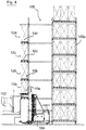
Figure 4 is a schematic side view of a row of shelves of a shelf system according to the invention with a plurality of pallet transfer stations arranged one above the other; and -
Figure 5 is a schematic plan view of two adjacent shelves of a shelf system according to the invention. -
Figure 6 a plan view of another embodiment of an arrangement for contour control according to the invention.
In
Auf dem Palettenübergabeplatz 12 steht in
Der trichterförmige Vorsprung 20d weist hierbei an einer Längsseite des Zentrierrahmens 20 eine erste Durchbrechung 22a und an einer Breitenseite des Zentrierrahmens 20 eine zweite Durchbrechung 22b auf. Die erste Durchbrechung 22a ist dazu vorgesehen, dass von dieser Seite her durch ein Flurförderzeug eine Palette in den Zentrierrahmen eingesetzt werden kann, wobei die Ausnehmung 22a dazu vorgesehen ist, der Gabel des Flurförderzeugs das Absetzen der Palette zu ermöglichen. In ähnlicher Weise ist die zweite Durchbrechung 22b dazu vorgesehen, dass von der Breitseite des Zentrierrahmens 20 her ein Regalbediengerät die in dem Zentrierrahmen aufstehende Palette nach erfolgter Konturenkontrolle übernehmen kann, um sie anschließend in das Regalsystem einzulagern.The funnel-shaped
Bei einem Absetzen der Palette in einem Zentrierrahmen 20, der wie angesprochen als Palettenübergabeplatz dient, wird durch die trichterförmige Ausbildung des Vorsprungs 20d erreicht, dass die Palette der Schwerkraft folgend das trichterförmige Profil hinabgleiten kann und exakt an der für sie vorbestimmten Position zum Aufstehen kommen wird. Hierdurch kann die anschließende Konturenkontrolle mit hoher Präzision durchgeführt werden, da die Position der zu erfassenden Palette sehr genau festgelegt und bekannt ist.When the pallet is set down in a centering
Die
Die optische Ausgabevorrichtung 24 kann beispielsweise unterhalb des Palettenübergabeplatzes 12 aus
Zur Vereinfachung der Lokalisierung des Überstands der Palette aus der Kontur ist ferner das zweite Anzeigeelement 24b vorgesehen, das mit insgesamt vier Lampen ausgerüstet ist, die mit den Buchstaben L, H, R und V bezeichnet sind, was im Einzelnen jeweils für "links", "hinten", "rechts" und "vorne" steht. In dem in
In
Wie ebenfalls zu erkennen ist, befinden sich an dem Stirnende der einen Teil des Regalsystems 100 bildenden Regalreihe 100a vier Palettenübergabeplätze 12a-12d, die jeweils Teil einer erfindungsgemäßen Anordnung zur Konturenkontrolle 10a-10d sind, wobei aus Gründen der Übersichtlichkeit auf eine Darstellung der jeweiligen Sensoreinheiten verzichtet worden ist. Das Einlagern von Paletten läuft nun dermaßen ab, dass das Flurförderzeug 102 eine Palette von einem Wareneingang oder aus einem zwischengeschalteten Lager aufnimmt und auf einen der Palettenübergabeplätze 12a-12d absetzt. Auf diesem Palettenübergabeplatz wird dann mittels der jeweils zugeordneten Anordnung zur Konturenkontrolle 10a-10d durch die jeweiligen Sensoreinrichtungen die anhand von
Je nach Ergebnis der Erfassung wird dann die Palette für die Einlagerung in das Regalsystem 100 durch das Regalbediengerät 104 freigegeben oder muss vom Fahrer des Flurförderzeugs 102 wieder vom Palettenübergabeplatz 12a-12d abgenommen werden, damit der Überstand der Palette am Boden behoben werden kann. Hierbei kann die Freigabe der Palette zur Einlagerung durch das Regalbediengerät 104 entweder automatisch durch eine Weitergabe der Sensordaten von der Ausgabeeinheit der jeweiligen Anordnung zur Konturenkontrolle 10a-10d an ein übergeordnetes Lagerverwaltungssystem oder händisch durch den Fahrer des Flurförderzeugs 102 anhand des ihm von der optischen Ausgabevorrichtung angezeigten Erfassungsergebnisses der Sensoreinheit durchgeführt werden.Depending on the result of the detection, the pallet is then released for storage in the
In
Indem jeweils benachbarte Regalreihen abwechselnd mit Palettenübergabeplätzen 12 für einzulagernde Paletten und Palettenübergabeplätzen 108 für auszulagernde Paletten angeordnet werden, können die Arbeitsabläufe in dem Automatikbereich des Regalsystems 100 derart optimiert werden, dass nach Auslagern einer Palette auf dem Palettenübergabeplatz 108 das in
Merkmale, die funktional oder gegenständlich Merkmalen des oben erläuterten Ausführungsbeispiels entsprechen, sind in
Claims (12)
- Arrangement for checking the contour of pallets (18) to be stored in a rack system, comprising:a pallet transfer station (12) which is designed to be able to receive pallets (18) to be stored in the rack system;at least one sensor device (16a-16d) which is designed to detect whether a pallet (18) standing on the pallet transfer station (12) and objects carried by the pallet (18) are completely within a predefined contour; andan output unit (24) which is operationally coupled to the sensor unit (16a-16d) and is designed to output the detection result, characterised in that a centring frame (20) is associated with the pallet transfer station (12), which frame has a profile (20d) which tapers in the manner of a funnel in the direction of a placement surface (20a-20c) for the pallet.
- Arrangement according to claim 1, wherein the sensor device (16a-16d) comprises at least one light barrier (16a-16d) and/or at least one camera, for example a 3D camera.
- Arrangement according to either claim 1 or claim 2, wherein the predefined contour, in plan view of the pallet (18), is formed by a polygon, such as a rectangle, and optionally a predetermined permissible height of the pallet (18) and of the objects carried by the pallet (18).
- Arrangement according to any of the preceding claims, wherein it further comprises means for detecting the weight of the pallet and/or the board clearance of the pallet (18), which means are also operationally coupled to the output unit (24).
- Arrangement according to any of the preceding claims, wherein the output unit (24) comprises an optical output apparatus which is designed to display the detection result of the sensor unit (16a-16d) to an operator and which is preferably arranged below the pallet transfer station (12).
- Rack system comprising at least one rack row (100a; 106a, 106b) and at least one rack operating device (104) and at least one arrangement for contour checking according to any of the preceding claims, the pallet transfer station (12a-12d) of which is designed in such a way that pallets can be placed thereon from outside the rack system and can then be picked up by the rack operating device (104) for storage.
- Rack system according to claim 6, wherein the pallet transfer station (12a-12d) is provided on a cantilever arm at one longitudinal end of the at least one rack row (100a; 106a), which cantilever arm preferably forms an extension of a rack support.
- Rack system according to either claim 6 or claim 7, wherein a plurality of pallet transfer stations (12a-12d) is provided, in particular on cantilever arms arranged one above the other at one longitudinal end of a single rack row (100a; 106a).
- Rack system according to claim 8, wherein each of the plurality of pallet transfer stations is associated with an optical output apparatus (24).
- Rack system according to claim 9, wherein a plurality of pallet transfer stations (12a-12d) arranged one above the other is provided and the respective optical output apparatuses (24) are all arranged below the bottommost pallet transfer station (12a).
- Rack system according to any of claims 6 to 10, wherein a first type of rack row (106a) is provided which comprises, at one longitudinal end, at least one pallet transfer station (12) for pallets to be stored, and a second type of rack row (106b) is provided which comprises, at one longitudinal end, at least one pallet output station (108) for pallets to be retrieved, and wherein rack rows of the first (106a) and second (106b) type are preferably arranged alternately.
- Rack system according to any of claims 6 to 11, wherein the output unit (24) is operationally coupled to a superordinate warehouse management system.
Applications Claiming Priority (2)
| Application Number | Priority Date | Filing Date | Title |
|---|---|---|---|
| DE102016208995.1A DE102016208995B4 (en) | 2016-05-24 | 2016-05-24 | Shelving system comprising an arrangement for checking the contours of pallets to be stored in a shelving system |
| PCT/EP2017/062380 WO2017202832A1 (en) | 2016-05-24 | 2017-05-23 | Transfer with contour checking |
Publications (2)
| Publication Number | Publication Date |
|---|---|
| EP3464124A1 EP3464124A1 (en) | 2019-04-10 |
| EP3464124B1 true EP3464124B1 (en) | 2020-07-29 |
Family
ID=59009667
Family Applications (1)
| Application Number | Title | Priority Date | Filing Date |
|---|---|---|---|
| EP17727826.4A Active EP3464124B1 (en) | 2016-05-24 | 2017-05-23 | Transfer with contour checking |
Country Status (6)
| Country | Link |
|---|---|
| US (1) | US11623819B2 (en) |
| EP (1) | EP3464124B1 (en) |
| DE (1) | DE102016208995B4 (en) |
| ES (1) | ES2812157T3 (en) |
| HU (1) | HUE050899T2 (en) |
| WO (1) | WO2017202832A1 (en) |
Cited By (1)
| Publication number | Priority date | Publication date | Assignee | Title |
|---|---|---|---|---|
| EP4286299A1 (en) | 2022-06-02 | 2023-12-06 | Jungheinrich Aktiengesellschaft | Device and method for controlling a contour of a load taken up on an industrial truck |
Families Citing this family (4)
| Publication number | Priority date | Publication date | Assignee | Title |
|---|---|---|---|---|
| US11481567B2 (en) | 2018-12-21 | 2022-10-25 | Hand Held Products, Inc. | Methods and systems of package processing in a material handling environment |
| JP7322905B2 (en) * | 2021-01-29 | 2023-08-08 | 株式会社ダイフク | Pallet inspection device |
| GB2618599A (en) * | 2022-05-12 | 2023-11-15 | Three Smith Group Ltd | Pallet sensor system |
| CN115108227B (en) * | 2022-08-08 | 2023-08-29 | 青岛盈智科技有限公司 | Method and system for warehousing goods in vertical warehouse of stacker for cold chain warehousing |
Family Cites Families (17)
| Publication number | Priority date | Publication date | Assignee | Title |
|---|---|---|---|---|
| DE119999C (en) | ||||
| DD119999A1 (en) * | 1975-07-07 | 1976-05-20 | ||
| US4540325A (en) * | 1983-04-18 | 1985-09-10 | Heisler Raymond A | Upstacker apparatus with biased gripping means |
| SE451831B (en) * | 1985-09-16 | 1987-11-02 | Knight Konsult Ing | material handling systems |
| US4658715A (en) * | 1986-04-14 | 1987-04-21 | Stobb Inc. | System for automating the palletizing of bundles |
| DE29505136U1 (en) | 1995-03-25 | 1995-06-22 | AKL-tec Lagersysteme GmbH, 57518 Alsdorf | Measuring device for determining a loading volume |
| JPH08301449A (en) | 1995-04-28 | 1996-11-19 | Murata Mach Ltd | Picking system |
| US6422806B1 (en) * | 2000-03-28 | 2002-07-23 | Kolinahr Systems, Inc. | Pallet stacker system |
| JP2001294303A (en) | 2000-04-10 | 2001-10-23 | Murata Mach Ltd | Article transport device |
| JP3482938B2 (en) | 2000-05-02 | 2004-01-06 | 株式会社ダイフク | Article position recognition device |
| JP2003097918A (en) | 2001-09-27 | 2003-04-03 | Kanebo Ltd | Program for processing image using image processing device, or computer, and recording medium storing the same |
| US7325667B1 (en) * | 2003-10-10 | 2008-02-05 | Damick Keith D | Systems and methods for feeding articles to and removing articles from an automatic washer |
| JP5348491B2 (en) | 2009-08-24 | 2013-11-20 | 株式会社ダイフク | Warehouse equipment |
| US9796540B1 (en) * | 2010-06-30 | 2017-10-24 | Thiele Technologies | System and method for robotic palletization of packages susceptible to package-to-package dimensional creep |
| DE102014111656A1 (en) | 2014-08-14 | 2016-02-18 | BIBA - Bremer Institut für Produktion und Logistik GmbH | Apparatus and method for camera-based contour control |
| US20160187186A1 (en) * | 2014-12-31 | 2016-06-30 | Nate J. Coleman | System and method to measure force or location on an l-beam |
| DE102016102251A1 (en) | 2016-02-10 | 2017-08-10 | Ltw Intralogistics Gmbh | analysis station |
-
2016
- 2016-05-24 DE DE102016208995.1A patent/DE102016208995B4/en active Active
-
2017
- 2017-05-23 WO PCT/EP2017/062380 patent/WO2017202832A1/en active Search and Examination
- 2017-05-23 HU HUE17727826A patent/HUE050899T2/en unknown
- 2017-05-23 EP EP17727826.4A patent/EP3464124B1/en active Active
- 2017-05-23 US US16/304,019 patent/US11623819B2/en active Active
- 2017-05-23 ES ES17727826T patent/ES2812157T3/en active Active
Non-Patent Citations (1)
| Title |
|---|
| None * |
Cited By (1)
| Publication number | Priority date | Publication date | Assignee | Title |
|---|---|---|---|---|
| EP4286299A1 (en) | 2022-06-02 | 2023-12-06 | Jungheinrich Aktiengesellschaft | Device and method for controlling a contour of a load taken up on an industrial truck |
Also Published As
| Publication number | Publication date |
|---|---|
| US20200317444A1 (en) | 2020-10-08 |
| EP3464124A1 (en) | 2019-04-10 |
| WO2017202832A1 (en) | 2017-11-30 |
| ES2812157T3 (en) | 2021-03-16 |
| HUE050899T2 (en) | 2021-01-28 |
| DE102016208995B4 (en) | 2022-07-14 |
| DE102016208995A1 (en) | 2017-11-30 |
| US11623819B2 (en) | 2023-04-11 |
Similar Documents
| Publication | Publication Date | Title |
|---|---|---|
| EP3464124B1 (en) | Transfer with contour checking | |
| AT516875B1 (en) | Method for storing piece goods in a storage rack and storage system | |
| EP1641687B2 (en) | Commissioning area and method for commissioning using a light grille | |
| EP2984007B1 (en) | Storage and order-picking system for the fully-automated identification and picking of articles, and corresponding order-picking station | |
| EP2468678A1 (en) | Industrial truck with a sensor for detecting the surroundings and method for operating such an industrial truck | |
| WO2013053747A1 (en) | System and procedure for manual batch-picking using the goods-to-man principle | |
| DE102016120386A1 (en) | Method for detecting objects in a warehouse and industrial truck with a device for detecting objects in a warehouse | |
| EP3657123B1 (en) | Gravity feed rack unit and control system for a gravity feed rack | |
| DE102019109007A1 (en) | Industrial truck and method of operating the same | |
| DE10033857A1 (en) | Storage system operating device is remotely controllable by operator via remote control unit; controller positions device coarsely, control unit automatically performs storage/extraction | |
| DE102016203674A1 (en) | Method for operating a continuous machine and continuous machine | |
| DE202019102253U1 (en) | Device for verifying storage goods positions in intralogistic storage systems | |
| EP2452900B1 (en) | Rollcontainer loading station, commissioning system with such a station and corresponding methods | |
| DE10016693B4 (en) | Board stacking and distribution system | |
| EP3141497B1 (en) | Method for storing a number of identical articles in a commissioning system | |
| DE102005035262B4 (en) | Shelf warehouse with input station | |
| DE102008048367C5 (en) | Storage device with overhang control | |
| EP3323517A1 (en) | Sorting system and method for tracking the sorting of a sorted item in a sorting register | |
| EP3854731B1 (en) | Device and method for separated piece goods | |
| DE102015105942B4 (en) | Method and device for intermediate storage on a conveyor belt when storing objects in a shelving system | |
| WO2007014963A1 (en) | Device for the contactless detection of the filling level of a commissioning installation | |
| EP3678792B1 (en) | Device and method for removing containers which have been incorrectly imprinted in a direct printing machine | |
| DE3740558A1 (en) | METHOD AND DEVICE FOR CONTROLLING A LIFTING CAR | |
| DE202008006941U1 (en) | Workplace for picking goods | |
| WO2024110100A1 (en) | Method for storing a plurality of piece goods in an order-picking apparatus |
Legal Events
| Date | Code | Title | Description |
|---|---|---|---|
| STAA | Information on the status of an ep patent application or granted ep patent |
Free format text: STATUS: UNKNOWN |
|
| STAA | Information on the status of an ep patent application or granted ep patent |
Free format text: STATUS: THE INTERNATIONAL PUBLICATION HAS BEEN MADE |
|
| PUAI | Public reference made under article 153(3) epc to a published international application that has entered the european phase |
Free format text: ORIGINAL CODE: 0009012 |
|
| STAA | Information on the status of an ep patent application or granted ep patent |
Free format text: STATUS: REQUEST FOR EXAMINATION WAS MADE |
|
| 17P | Request for examination filed |
Effective date: 20181127 |
|
| AK | Designated contracting states |
Kind code of ref document: A1 Designated state(s): AL AT BE BG CH CY CZ DE DK EE ES FI FR GB GR HR HU IE IS IT LI LT LU LV MC MK MT NL NO PL PT RO RS SE SI SK SM TR |
|
| AX | Request for extension of the european patent |
Extension state: BA ME |
|
| DAV | Request for validation of the european patent (deleted) | ||
| DAX | Request for extension of the european patent (deleted) | ||
| GRAP | Despatch of communication of intention to grant a patent |
Free format text: ORIGINAL CODE: EPIDOSNIGR1 |
|
| STAA | Information on the status of an ep patent application or granted ep patent |
Free format text: STATUS: GRANT OF PATENT IS INTENDED |
|
| INTG | Intention to grant announced |
Effective date: 20200317 |
|
| GRAS | Grant fee paid |
Free format text: ORIGINAL CODE: EPIDOSNIGR3 |
|
| GRAA | (expected) grant |
Free format text: ORIGINAL CODE: 0009210 |
|
| STAA | Information on the status of an ep patent application or granted ep patent |
Free format text: STATUS: THE PATENT HAS BEEN GRANTED |
|
| AK | Designated contracting states |
Kind code of ref document: B1 Designated state(s): AL AT BE BG CH CY CZ DE DK EE ES FI FR GB GR HR HU IE IS IT LI LT LU LV MC MK MT NL NO PL PT RO RS SE SI SK SM TR |
|
| REG | Reference to a national code |
Ref country code: CH Ref legal event code: EP |
|
| REG | Reference to a national code |
Ref country code: AT Ref legal event code: REF Ref document number: 1295534 Country of ref document: AT Kind code of ref document: T Effective date: 20200815 |
|
| REG | Reference to a national code |
Ref country code: IE Ref legal event code: FG4D Free format text: LANGUAGE OF EP DOCUMENT: GERMAN |
|
| REG | Reference to a national code |
Ref country code: DE Ref legal event code: R096 Ref document number: 502017006439 Country of ref document: DE |
|
| REG | Reference to a national code |
Ref country code: NL Ref legal event code: FP |
|
| REG | Reference to a national code |
Ref country code: SE Ref legal event code: TRGR |
|
| REG | Reference to a national code |
Ref country code: NO Ref legal event code: T2 Effective date: 20200729 |
|
| REG | Reference to a national code |
Ref country code: LT Ref legal event code: MG4D |
|
| REG | Reference to a national code |
Ref country code: HU Ref legal event code: AG4A Ref document number: E050899 Country of ref document: HU |
|
| PG25 | Lapsed in a contracting state [announced via postgrant information from national office to epo] |
Ref country code: PT Free format text: LAPSE BECAUSE OF FAILURE TO SUBMIT A TRANSLATION OF THE DESCRIPTION OR TO PAY THE FEE WITHIN THE PRESCRIBED TIME-LIMIT Effective date: 20201130 Ref country code: FI Free format text: LAPSE BECAUSE OF FAILURE TO SUBMIT A TRANSLATION OF THE DESCRIPTION OR TO PAY THE FEE WITHIN THE PRESCRIBED TIME-LIMIT Effective date: 20200729 Ref country code: GR Free format text: LAPSE BECAUSE OF FAILURE TO SUBMIT A TRANSLATION OF THE DESCRIPTION OR TO PAY THE FEE WITHIN THE PRESCRIBED TIME-LIMIT Effective date: 20201030 Ref country code: BG Free format text: LAPSE BECAUSE OF FAILURE TO SUBMIT A TRANSLATION OF THE DESCRIPTION OR TO PAY THE FEE WITHIN THE PRESCRIBED TIME-LIMIT Effective date: 20201029 Ref country code: LT Free format text: LAPSE BECAUSE OF FAILURE TO SUBMIT A TRANSLATION OF THE DESCRIPTION OR TO PAY THE FEE WITHIN THE PRESCRIBED TIME-LIMIT Effective date: 20200729 Ref country code: HR Free format text: LAPSE BECAUSE OF FAILURE TO SUBMIT A TRANSLATION OF THE DESCRIPTION OR TO PAY THE FEE WITHIN THE PRESCRIBED TIME-LIMIT Effective date: 20200729 |
|
| PG25 | Lapsed in a contracting state [announced via postgrant information from national office to epo] |
Ref country code: PL Free format text: LAPSE BECAUSE OF FAILURE TO SUBMIT A TRANSLATION OF THE DESCRIPTION OR TO PAY THE FEE WITHIN THE PRESCRIBED TIME-LIMIT Effective date: 20200729 Ref country code: LV Free format text: LAPSE BECAUSE OF FAILURE TO SUBMIT A TRANSLATION OF THE DESCRIPTION OR TO PAY THE FEE WITHIN THE PRESCRIBED TIME-LIMIT Effective date: 20200729 Ref country code: RS Free format text: LAPSE BECAUSE OF FAILURE TO SUBMIT A TRANSLATION OF THE DESCRIPTION OR TO PAY THE FEE WITHIN THE PRESCRIBED TIME-LIMIT Effective date: 20200729 Ref country code: IS Free format text: LAPSE BECAUSE OF FAILURE TO SUBMIT A TRANSLATION OF THE DESCRIPTION OR TO PAY THE FEE WITHIN THE PRESCRIBED TIME-LIMIT Effective date: 20201129 |
|
| REG | Reference to a national code |
Ref country code: ES Ref legal event code: FG2A Ref document number: 2812157 Country of ref document: ES Kind code of ref document: T3 Effective date: 20210316 |
|
| PG25 | Lapsed in a contracting state [announced via postgrant information from national office to epo] |
Ref country code: RO Free format text: LAPSE BECAUSE OF FAILURE TO SUBMIT A TRANSLATION OF THE DESCRIPTION OR TO PAY THE FEE WITHIN THE PRESCRIBED TIME-LIMIT Effective date: 20200729 Ref country code: DK Free format text: LAPSE BECAUSE OF FAILURE TO SUBMIT A TRANSLATION OF THE DESCRIPTION OR TO PAY THE FEE WITHIN THE PRESCRIBED TIME-LIMIT Effective date: 20200729 Ref country code: CZ Free format text: LAPSE BECAUSE OF FAILURE TO SUBMIT A TRANSLATION OF THE DESCRIPTION OR TO PAY THE FEE WITHIN THE PRESCRIBED TIME-LIMIT Effective date: 20200729 Ref country code: SM Free format text: LAPSE BECAUSE OF FAILURE TO SUBMIT A TRANSLATION OF THE DESCRIPTION OR TO PAY THE FEE WITHIN THE PRESCRIBED TIME-LIMIT Effective date: 20200729 Ref country code: EE Free format text: LAPSE BECAUSE OF FAILURE TO SUBMIT A TRANSLATION OF THE DESCRIPTION OR TO PAY THE FEE WITHIN THE PRESCRIBED TIME-LIMIT Effective date: 20200729 |
|
| REG | Reference to a national code |
Ref country code: DE Ref legal event code: R097 Ref document number: 502017006439 Country of ref document: DE |
|
| PG25 | Lapsed in a contracting state [announced via postgrant information from national office to epo] |
Ref country code: AL Free format text: LAPSE BECAUSE OF FAILURE TO SUBMIT A TRANSLATION OF THE DESCRIPTION OR TO PAY THE FEE WITHIN THE PRESCRIBED TIME-LIMIT Effective date: 20200729 |
|
| PLBE | No opposition filed within time limit |
Free format text: ORIGINAL CODE: 0009261 |
|
| STAA | Information on the status of an ep patent application or granted ep patent |
Free format text: STATUS: NO OPPOSITION FILED WITHIN TIME LIMIT |
|
| PG25 | Lapsed in a contracting state [announced via postgrant information from national office to epo] |
Ref country code: SK Free format text: LAPSE BECAUSE OF FAILURE TO SUBMIT A TRANSLATION OF THE DESCRIPTION OR TO PAY THE FEE WITHIN THE PRESCRIBED TIME-LIMIT Effective date: 20200729 |
|
| 26N | No opposition filed |
Effective date: 20210430 |
|
| PG25 | Lapsed in a contracting state [announced via postgrant information from national office to epo] |
Ref country code: SI Free format text: LAPSE BECAUSE OF FAILURE TO SUBMIT A TRANSLATION OF THE DESCRIPTION OR TO PAY THE FEE WITHIN THE PRESCRIBED TIME-LIMIT Effective date: 20200729 |
|
| REG | Reference to a national code |
Ref country code: CH Ref legal event code: PL |
|
| PG25 | Lapsed in a contracting state [announced via postgrant information from national office to epo] |
Ref country code: CH Free format text: LAPSE BECAUSE OF NON-PAYMENT OF DUE FEES Effective date: 20210531 Ref country code: LI Free format text: LAPSE BECAUSE OF NON-PAYMENT OF DUE FEES Effective date: 20210531 Ref country code: LU Free format text: LAPSE BECAUSE OF NON-PAYMENT OF DUE FEES Effective date: 20210523 Ref country code: MC Free format text: LAPSE BECAUSE OF FAILURE TO SUBMIT A TRANSLATION OF THE DESCRIPTION OR TO PAY THE FEE WITHIN THE PRESCRIBED TIME-LIMIT Effective date: 20200729 |
|
| PG25 | Lapsed in a contracting state [announced via postgrant information from national office to epo] |
Ref country code: CY Free format text: LAPSE BECAUSE OF FAILURE TO SUBMIT A TRANSLATION OF THE DESCRIPTION OR TO PAY THE FEE WITHIN THE PRESCRIBED TIME-LIMIT Effective date: 20200729 |
|
| PGFP | Annual fee paid to national office [announced via postgrant information from national office to epo] |
Ref country code: IT Payment date: 20230531 Year of fee payment: 7 |
|
| P01 | Opt-out of the competence of the unified patent court (upc) registered |
Effective date: 20230628 |
|
| PG25 | Lapsed in a contracting state [announced via postgrant information from national office to epo] |
Ref country code: MK Free format text: LAPSE BECAUSE OF FAILURE TO SUBMIT A TRANSLATION OF THE DESCRIPTION OR TO PAY THE FEE WITHIN THE PRESCRIBED TIME-LIMIT Effective date: 20200729 |
|
| PGFP | Annual fee paid to national office [announced via postgrant information from national office to epo] |
Ref country code: NL Payment date: 20240522 Year of fee payment: 8 |
|
| PG25 | Lapsed in a contracting state [announced via postgrant information from national office to epo] |
Ref country code: TR Free format text: LAPSE BECAUSE OF FAILURE TO SUBMIT A TRANSLATION OF THE DESCRIPTION OR TO PAY THE FEE WITHIN THE PRESCRIBED TIME-LIMIT Effective date: 20200729 |
|
| PGFP | Annual fee paid to national office [announced via postgrant information from national office to epo] |
Ref country code: IE Payment date: 20240517 Year of fee payment: 8 |
|
| PGFP | Annual fee paid to national office [announced via postgrant information from national office to epo] |
Ref country code: GB Payment date: 20240522 Year of fee payment: 8 |
|
| PGFP | Annual fee paid to national office [announced via postgrant information from national office to epo] |
Ref country code: DE Payment date: 20240517 Year of fee payment: 8 |
|
| PGFP | Annual fee paid to national office [announced via postgrant information from national office to epo] |
Ref country code: ES Payment date: 20240614 Year of fee payment: 8 |
|
| PGFP | Annual fee paid to national office [announced via postgrant information from national office to epo] |
Ref country code: AT Payment date: 20240517 Year of fee payment: 8 |
|
| PGFP | Annual fee paid to national office [announced via postgrant information from national office to epo] |
Ref country code: NO Payment date: 20240521 Year of fee payment: 8 Ref country code: FR Payment date: 20240522 Year of fee payment: 8 |
|
| PGFP | Annual fee paid to national office [announced via postgrant information from national office to epo] |
Ref country code: SE Payment date: 20240522 Year of fee payment: 8 Ref country code: HU Payment date: 20240524 Year of fee payment: 8 Ref country code: BE Payment date: 20240521 Year of fee payment: 8 |