EP3463980B1 - A lamp assembly for a vehicle - Google Patents
A lamp assembly for a vehicle Download PDFInfo
- Publication number
- EP3463980B1 EP3463980B1 EP17726933.9A EP17726933A EP3463980B1 EP 3463980 B1 EP3463980 B1 EP 3463980B1 EP 17726933 A EP17726933 A EP 17726933A EP 3463980 B1 EP3463980 B1 EP 3463980B1
- Authority
- EP
- European Patent Office
- Prior art keywords
- light
- lamp assembly
- light guide
- housing
- enclosure
- Prior art date
- Legal status (The legal status is an assumption and is not a legal conclusion. Google has not performed a legal analysis and makes no representation as to the accuracy of the status listed.)
- Active
Links
Images


Classifications
-
- F—MECHANICAL ENGINEERING; LIGHTING; HEATING; WEAPONS; BLASTING
- F21—LIGHTING
- F21S—NON-PORTABLE LIGHTING DEVICES; SYSTEMS THEREOF; VEHICLE LIGHTING DEVICES SPECIALLY ADAPTED FOR VEHICLE EXTERIORS
- F21S43/00—Signalling devices specially adapted for vehicle exteriors, e.g. brake lamps, direction indicator lights or reversing lights
- F21S43/20—Signalling devices specially adapted for vehicle exteriors, e.g. brake lamps, direction indicator lights or reversing lights characterised by refractors, transparent cover plates, light guides or filters
- F21S43/235—Light guides
- F21S43/242—Light guides characterised by the emission area
- F21S43/245—Light guides characterised by the emission area emitting light from one or more of its major surfaces
-
- B—PERFORMING OPERATIONS; TRANSPORTING
- B60—VEHICLES IN GENERAL
- B60Q—ARRANGEMENT OF SIGNALLING OR LIGHTING DEVICES, THE MOUNTING OR SUPPORTING THEREOF OR CIRCUITS THEREFOR, FOR VEHICLES IN GENERAL
- B60Q1/00—Arrangement of optical signalling or lighting devices, the mounting or supporting thereof or circuits therefor
- B60Q1/26—Arrangement of optical signalling or lighting devices, the mounting or supporting thereof or circuits therefor the devices being primarily intended to indicate the vehicle, or parts thereof, or to give signals, to other traffic
- B60Q1/2661—Arrangement of optical signalling or lighting devices, the mounting or supporting thereof or circuits therefor the devices being primarily intended to indicate the vehicle, or parts thereof, or to give signals, to other traffic mounted on parts having other functions
- B60Q1/2665—Arrangement of optical signalling or lighting devices, the mounting or supporting thereof or circuits therefor the devices being primarily intended to indicate the vehicle, or parts thereof, or to give signals, to other traffic mounted on parts having other functions on rear-view mirrors
-
- B—PERFORMING OPERATIONS; TRANSPORTING
- B60—VEHICLES IN GENERAL
- B60R—VEHICLES, VEHICLE FITTINGS, OR VEHICLE PARTS, NOT OTHERWISE PROVIDED FOR
- B60R1/00—Optical viewing arrangements; Real-time viewing arrangements for drivers or passengers using optical image capturing systems, e.g. cameras or video systems specially adapted for use in or on vehicles
- B60R1/12—Mirror assemblies combined with other articles, e.g. clocks
- B60R1/1207—Mirror assemblies combined with other articles, e.g. clocks with lamps; with turn indicators
-
- F—MECHANICAL ENGINEERING; LIGHTING; HEATING; WEAPONS; BLASTING
- F21—LIGHTING
- F21S—NON-PORTABLE LIGHTING DEVICES; SYSTEMS THEREOF; VEHICLE LIGHTING DEVICES SPECIALLY ADAPTED FOR VEHICLE EXTERIORS
- F21S43/00—Signalling devices specially adapted for vehicle exteriors, e.g. brake lamps, direction indicator lights or reversing lights
- F21S43/10—Signalling devices specially adapted for vehicle exteriors, e.g. brake lamps, direction indicator lights or reversing lights characterised by the light source
- F21S43/13—Signalling devices specially adapted for vehicle exteriors, e.g. brake lamps, direction indicator lights or reversing lights characterised by the light source characterised by the type of light source
- F21S43/14—Light emitting diodes [LED]
-
- F—MECHANICAL ENGINEERING; LIGHTING; HEATING; WEAPONS; BLASTING
- F21—LIGHTING
- F21S—NON-PORTABLE LIGHTING DEVICES; SYSTEMS THEREOF; VEHICLE LIGHTING DEVICES SPECIALLY ADAPTED FOR VEHICLE EXTERIORS
- F21S43/00—Signalling devices specially adapted for vehicle exteriors, e.g. brake lamps, direction indicator lights or reversing lights
- F21S43/20—Signalling devices specially adapted for vehicle exteriors, e.g. brake lamps, direction indicator lights or reversing lights characterised by refractors, transparent cover plates, light guides or filters
- F21S43/235—Light guides
- F21S43/236—Light guides characterised by the shape of the light guide
- F21S43/237—Light guides characterised by the shape of the light guide rod-shaped
-
- F—MECHANICAL ENGINEERING; LIGHTING; HEATING; WEAPONS; BLASTING
- F21—LIGHTING
- F21S—NON-PORTABLE LIGHTING DEVICES; SYSTEMS THEREOF; VEHICLE LIGHTING DEVICES SPECIALLY ADAPTED FOR VEHICLE EXTERIORS
- F21S43/00—Signalling devices specially adapted for vehicle exteriors, e.g. brake lamps, direction indicator lights or reversing lights
- F21S43/20—Signalling devices specially adapted for vehicle exteriors, e.g. brake lamps, direction indicator lights or reversing lights characterised by refractors, transparent cover plates, light guides or filters
- F21S43/235—Light guides
- F21S43/249—Light guides with two or more light sources being coupled into the light guide
-
- F—MECHANICAL ENGINEERING; LIGHTING; HEATING; WEAPONS; BLASTING
- F21—LIGHTING
- F21S—NON-PORTABLE LIGHTING DEVICES; SYSTEMS THEREOF; VEHICLE LIGHTING DEVICES SPECIALLY ADAPTED FOR VEHICLE EXTERIORS
- F21S43/00—Signalling devices specially adapted for vehicle exteriors, e.g. brake lamps, direction indicator lights or reversing lights
- F21S43/20—Signalling devices specially adapted for vehicle exteriors, e.g. brake lamps, direction indicator lights or reversing lights characterised by refractors, transparent cover plates, light guides or filters
- F21S43/26—Refractors, transparent cover plates, light guides or filters not provided in groups F21S43/235 - F21S43/255
-
- F—MECHANICAL ENGINEERING; LIGHTING; HEATING; WEAPONS; BLASTING
- F21—LIGHTING
- F21S—NON-PORTABLE LIGHTING DEVICES; SYSTEMS THEREOF; VEHICLE LIGHTING DEVICES SPECIALLY ADAPTED FOR VEHICLE EXTERIORS
- F21S43/00—Signalling devices specially adapted for vehicle exteriors, e.g. brake lamps, direction indicator lights or reversing lights
- F21S43/20—Signalling devices specially adapted for vehicle exteriors, e.g. brake lamps, direction indicator lights or reversing lights characterised by refractors, transparent cover plates, light guides or filters
- F21S43/27—Attachment thereof
-
- F—MECHANICAL ENGINEERING; LIGHTING; HEATING; WEAPONS; BLASTING
- F21—LIGHTING
- F21S—NON-PORTABLE LIGHTING DEVICES; SYSTEMS THEREOF; VEHICLE LIGHTING DEVICES SPECIALLY ADAPTED FOR VEHICLE EXTERIORS
- F21S45/00—Arrangements within vehicle lighting devices specially adapted for vehicle exteriors, for purposes other than emission or distribution of light
- F21S45/50—Waterproofing
-
- F—MECHANICAL ENGINEERING; LIGHTING; HEATING; WEAPONS; BLASTING
- F21—LIGHTING
- F21W—INDEXING SCHEME ASSOCIATED WITH SUBCLASSES F21K, F21L, F21S and F21V, RELATING TO USES OR APPLICATIONS OF LIGHTING DEVICES OR SYSTEMS
- F21W2103/00—Exterior vehicle lighting devices for signalling purposes
- F21W2103/15—Side marker lights
-
- F—MECHANICAL ENGINEERING; LIGHTING; HEATING; WEAPONS; BLASTING
- F21—LIGHTING
- F21W—INDEXING SCHEME ASSOCIATED WITH SUBCLASSES F21K, F21L, F21S and F21V, RELATING TO USES OR APPLICATIONS OF LIGHTING DEVICES OR SYSTEMS
- F21W2103/00—Exterior vehicle lighting devices for signalling purposes
- F21W2103/20—Direction indicator lights
- F21W2103/25—Direction indicator lights for rear-view mirrors
Definitions
- the present invention relates to lamp assemblies.
- the present invention relates to lamp assemblies for an exterior rear view assembly of a vehicle, in line with the preamble of claim 1.
- Automotive lighting arrangements are increasingly being used in vehicle rear view systems (such as exterior rear view mirror assemblies) as value added features required by automotive manufacturers.
- An example of this is rear view mirror assemblies that are manufactured with supplementary side direction indicators (or side turn signal indicator) lights, which are operated by the driver to signal their intention to change the direction in which the vehicle is proceeding.
- Side direction indicators or side turn signal indicator
- LEDs Light emitting diodes
- EP 2 774 814 A1 discloses a mirror indicator having a housing whose rear portion is made of opaque plastic material and is fixed to a rear portion of housing.
- a main optical waveguide is made of transparent plastic material.
- a light source is coupled to first end face of the main optical waveguide and to rear portion of housing facing away from the shell side of main optical waveguide.
- the rear portion of housing and either the main optical waveguide or separate auxiliary optical fiber are integrally formed by a 2-component injection-molded portion.
- EP 2 803 532 A1 refers to a mirror device for motor vehicles. It comprises an outer housing with a cover having a (PVD) coating; a lens; and illumination means such as LEDs, light guides, light emitting surfaces and/or blinkers.
- the lens has a first area internal to the cover, and a second, transparent area extending to one side of the outer housing.
- the cover has a first cover element external to the lens and of a nature such that the illumination means are visible from the exterior when they are on and not visible from the exterior when they are off.
- the cover has a substantially opaque second cover element having an overlapping portion between the first area of the lens and the first cover element.
- a coated polymeric substrate is known.
- the polymeric substrate is coated with a chromium-based reflective coating, and the polymeric substrate and the chromium-based reflective coating are at least in part permeable to light originating from at least one light element, wherein the coating is an alloy of chromium and a dopant material, the dopant material being selected from the hexagonally close-packed transition metals, the alloy having a crystal structure of a primary body-centered cubic phase in coexistence with a secondary omega hexagonally close-packed phase.
- DE 10 2012 211 821 A1 discloses a light unit for vehicle in particular the lamp unit having a housing shell defining an interior space for containing light sources and associated light-guiding elements.
- the housing shell is made of thermoplastic plastic material and manufactured by an injection molding process.
- a transparent window portion is formed in the housing shell.
- the light-guiding elements are formed in one-piece with the housing shell during injection molding process.
- the light guide element is formed with a coupling-out structure.
- a reflective layer is formed on the side opposite to the window portion of the surface portion of a covering shell.
- the exterior rearview mirror has a mirror head and a housing which has a recess for a repeater flashing indicator, which is provided with a lens and a light guide, in which at least one light source can be coupled light.
- the light guide extends on the outside of the lens and protrudes through the lens into the housing, so that the light coupling element is within the housing. The corresponding bulb is therefore not visible from the outside.
- the exterior rearview mirror is particularly suitable for motor vehicles. With the light guide, the legal requirements regarding the light values when flashing are met and a uniform illumination is achieved.
- US 2011/170307 A1 describes a vehicle lamp comprising a common substrate; a plurality of LED light sources arranged on the common substrate; a light guiding lens elongated in a direction in which the LED light sources are aligned; and a plurality of reflecting sections provided on the light guiding lens and configured to individually reflect incident lights from the respective LED light sources to a periphery of a vehicle, wherein respective directions of the reflecting sections are made to differ in accordance with positions of the corresponding LED light sources.
- EP 2 746 106 A1 teaches a vehicle component comprising: a molded cover molded into a shape of a surface of a part attached to a vehicle; and a surface-emitting device bonded or fitted and fixed along a back face of the molded cover, wherein the molded cover is vacuum formed by solid decorative molding of a translucent resin molded member with a translucent film, and light from the surface-emitting device is transmitted through the molded cover and emerges in a predetermined light-emitting area which is a part of a surface of the vehicle component.
- EP 1 914 118 A2 describes an exterior rearview mirror for vehicles with a mirror head, which is provided with a mirror glass and in which at least one lamp is housed, which emits light through at least one transparent area, and with a mirror base, wherein at least part of the housing of the mirror head and / or of the housing of the mirror base is made of at least two plastic layers, which have different light transmittance, and that in the transparent area the plastic layer with the lower light transmittance is missing or only has such a thickness that the light emitted by the lamp is sufficient Luminous intensity radiates outwards.
- a lighting arrangement which provides both a forward projecting light output (known as a cosmetic light due to it being for aesthetic rather than regulatory or compliance purposes) and a rear projecting light output (known as a compliance light) having a required photometric output for legal compliance purposes (for example, the requirements of Australian Design Rule 6/00 - Direction Indicators).
- a forward projecting light output known as a cosmetic light due to it being for aesthetic rather than regulatory or compliance purposes
- a rear projecting light output known as a compliance light having a required photometric output for legal compliance purposes (for example, the requirements of Australian Design Rule 6/00 - Direction Indicators).
- Light emitting devices within rear vision assemblies that employ an internal light pipe, or a light pipe integrated into an exterior lens are known. It is also known to weld such light pipes to a rear housing to achieve both cosmetic and regulatory requirements. However, this solution may not always be possible due to packaging and design requirements.
- a lamp assembly adapted to be integrated into an exterior rear view mirror assembly for a vehicle including:
- the lamp assembly provides a cosmetic light configured to provide light output generally forward of the vehicle and a compliance light configured to provide light output over a viewing angle of a least 55 degrees in a plane
- the outer lens includes an opaque inner portion and a light transmissive outer portion, wherein the opaque inner portion includes an elongate opening to allow light to transmit through the outer portion
- the lamp assembly further including an elongate cosmetic light pipe for guiding light from at least one light source to an elongate light emitting surface, wherein the elongate light pipe is housed within the enclosure such that the light emitting surface of the light pipe is adjacent to the elongate opening of the inner portion
- the compliance light guide features a mid-section with a reduced cross sectional area
- the outer lens features a complimentary cut out, wherein when the out lens is welded to the housing and compliance light guide so form a sealed enclosure over a viewing angle of at least 55 degrees in a plane, the mid-section nests within the cut out, wherein the lamp enclosure is weatherproof.
- the light is output from the light guide with a substantially uniform luminance.
- the plane is a horizontal plane.
- the light emitting surface of the light guide includes surface optics to diffuse light output from the light emitting surface.
- the housing is opaque.
- the light guide is clear.
- the lamp enclosure is weatherproof.
- a lamp assembly 200 integrated into an exterior rear view mirror assembly 100.
- the mirror assembly comprises a vehicle mounting portion 101 for mounting the assembly to the side of a vehicle, and a base frame 102 in connection with the vehicle mounting portion 101 for supporting the remainder of the mirror assembly 100.
- the lamp assembly 200 is supported by the base frame 102, and is enclosed by an outer case 103, which also houses the rear view mirror 104 and mirror surround 105.
- the lamp assembly 200 provides a cosmetic light configured to provide light output generally forward of the vehicle.
- the lamp assembly 200 also provides a compliance light configured to provide light output to an area required by law.
- FIG. 4 where there is shown a schematic top view of the minimum horizontal angle of light distribution in space to be provided by the compliance light, as required by Australian Design Rule 6/00 - Direction Indicators. It can be seen that the light output is required to be provided in a minimum 5 degree arc offset 5 degrees from a line parallel to the vehicle centreline. In this embodiment, the compliance light is configured to comply with these requirements.
- the housing 201 and compliance light guide 211 are formed in a two shot injection moulding process. First, the housing 201 is moulded from black acrylonitrile butadiene styrene (ABS) or other suitable opaque substrate, then the compliance light guide 211 is overmoulded using an acrylic (PMMA) or other suitable clear or transparent substrate.
- ABS black acrylonitrile butadiene styrene
- PMMA acrylic
- the lamp housing 201 and compliance light guide 211 may instead be separate components welded together.
- the lamp housing 201 supports and houses an elongate cosmetic light pipe 206, with an elongate light emitting surface 206a, the light pipe 206 being illuminated at its first and second ends by a first end PCB 207 and light source 208 and a second end PCB 209 and light source 210 respectively.
- the lamp housing 201 also supports and houses a PCB 216 and light source 217 for illuminating the compliance light guide 211.
- the light sources 208, 209, 217 may be light emitting diodes (LEDs).
- the cosmetic light pipe 206 is manufactured from a clear plastic (such as PMMA) and is adapted to be substantially transparent when in an un-lit state while being diffusive in a lit-state. When lit, light exits the light emitting surface 206a of the cosmetic light pipe 206 with substantially uniform luminous intensity along its length. This may be achieved by using surface optics along its length to distribute the light evenly along its length. Alternatively, the cosmetic light pipe 206 may be filled with light scattering particles, where most light rays that enter the light pipe 206 will encounter the light scattering particles that alter the direction of the rays. The effect of this light scattering is that light rays will spread throughout the light pipe 206, such that an even distribution of light output from the light emitting surface 206a occurs.
- a clear plastic such as PMMA
- the light scattering particles may be titanium dioxide particles of sufficient size and concentration such that the light pipe 206 appears transparent when un-lit while providing a substantially uniform luminous intensity surface output when lit.
- the light source 217 is immediately adjacent the light receiving surface 212 of the compliance light guide 211, such that light emitted from the light source is received by the light receiving surface 212 of the light guide 211, passes through the mid-section 213 and is directed toward the light emitting surface 214 of the light guide 211, such that light is output from the light guide 211 such that at least the minimum horizontal angle of light distribution in space is achieved.
- the light emitting surface 214 may have surface optics present to diffuse light output from the light emitting surface.
- the light guide 211 may be configured such that light is output from the light guide 211 with a substantially uniform luminance.
- the lamp assembly 200 including the outer lens 202.
- the outer lens 202 is formed in a two shot injection moulding process, comprising an opaque inner portion 203 and a light transmissive outer portion 205.
- the opaque inner portion 203 has an elongate opening 204 to allow light emitted from the adjacent light emitting surface 206a of the light pipe 206 to transmit through the light transmissive outer portion 205.
- the opaque inner portion 203 is manufactured from an opaque plastic (such as ABS), and the light transmissive outer portion 205 is manufactured from a clear or tinted plastic (such as PMMA).
- the outer lens 202 may be a single component having an opaque coating on an inner surface formed by example by applying paint or a thin film coating.
- the light transmissive window 203 may be formed by etching away the opaque coating or masking the area before coating.
- the outer lens 202 and housing 201 are welded together using hot plate welding and as best shown in Figure 7 , define a sealed, weatherproof enclosure housing the cosmetic light pipe 21, PCBs 207, 209, 216 and light sources 208, 210, 217.
- the exterior rear view mirror assembly 100 is configured such that the light receiving surface 212 of the compliance light guide 211 is within the enclosure, and the light emitting surface of the compliance light guide 211 is outside the enclosure, such that the only externally visible components of the lamp assembly 200 are the outer lens 202 and the light emitting surface 214 of the compliance light guide 211. It will be appreciated that the co-moulding or welding of the compliance light guide 211 to the housing 201 allows for it to be an external feature, while the enclosure remains fully sealed.
- the compliance light guide 211 features a mid-section 213 with a reduced cross sectional area.
- the outer lens 202 features a complementary cut out 218, wherein when the outer lens 202 is welded to the lamp housing 201 and compliance light guide 211 to form the sealed enclosure, the mid-section 213 nests within the cut out 218.
- the mirror surround 105 has a similar cut out (not shown) which also encloses the mid-section 213. such that the only visible component of the compliance light guide is the light emitting surface 214.
- FIG. 10 where there is shown a rear perspective view of an exterior rear view mirror assembly 300 according to an alternative embodiment.
- This embodiment includes the additional feature of a compliance light guide with a second light emitting surface 303 which is directed toward the driver of the vehicle and employed as a tell tale light to notify the driver that the compliance light is illuminated.
Landscapes
- Engineering & Computer Science (AREA)
- General Engineering & Computer Science (AREA)
- Mechanical Engineering (AREA)
- Physics & Mathematics (AREA)
- Microelectronics & Electronic Packaging (AREA)
- Optics & Photonics (AREA)
- Multimedia (AREA)
- Lighting Device Outwards From Vehicle And Optical Signal (AREA)
- Non-Portable Lighting Devices Or Systems Thereof (AREA)
Description
- The present invention relates to lamp assemblies. In a particular form the present invention relates to lamp assemblies for an exterior rear view assembly of a vehicle, in line with the preamble of claim 1.
- Automotive lighting arrangements are increasingly being used in vehicle rear view systems (such as exterior rear view mirror assemblies) as value added features required by automotive manufacturers. An example of this is rear view mirror assemblies that are manufactured with supplementary side direction indicators (or side turn signal indicator) lights, which are operated by the driver to signal their intention to change the direction in which the vehicle is proceeding. Light emitting diodes (LEDs) are also being used more frequently as the light source in these lighting arrangements.
-
EP 2 774 814 A1 discloses a mirror indicator having a housing whose rear portion is made of opaque plastic material and is fixed to a rear portion of housing. A main optical waveguide is made of transparent plastic material. A light source is coupled to first end face of the main optical waveguide and to rear portion of housing facing away from the shell side of main optical waveguide. The rear portion of housing and either the main optical waveguide or separate auxiliary optical fiber are integrally formed by a 2-component injection-molded portion. - Still further,
EP 2 803 532 A1 refers to a mirror device for motor vehicles. It comprises an outer housing with a cover having a (PVD) coating; a lens; and illumination means such as LEDs, light guides, light emitting surfaces and/or blinkers. The lens has a first area internal to the cover, and a second, transparent area extending to one side of the outer housing. The cover has a first cover element external to the lens and of a nature such that the illumination means are visible from the exterior when they are on and not visible from the exterior when they are off. The cover has a substantially opaque second cover element having an overlapping portion between the first area of the lens and the first cover element. - From
US 2016/0059773 A1 a coated polymeric substrate is known. The polymeric substrate is coated with a chromium-based reflective coating, and the polymeric substrate and the chromium-based reflective coating are at least in part permeable to light originating from at least one light element, wherein the coating is an alloy of chromium and a dopant material, the dopant material being selected from the hexagonally close-packed transition metals, the alloy having a crystal structure of a primary body-centered cubic phase in coexistence with a secondary omega hexagonally close-packed phase. -
DE 10 2012 211 821 A1 discloses a light unit for vehicle in particular the lamp unit having a housing shell defining an interior space for containing light sources and associated light-guiding elements. The housing shell is made of thermoplastic plastic material and manufactured by an injection molding process. A transparent window portion is formed in the housing shell. The light-guiding elements are formed in one-piece with the housing shell during injection molding process. The light guide element is formed with a coupling-out structure. A reflective layer is formed on the side opposite to the window portion of the surface portion of a covering shell. - From
DE 10 2005 013 682 A1 a rear view mirror for a vehicle is known. In particular, The exterior rearview mirror has a mirror head and a housing which has a recess for a repeater flashing indicator, which is provided with a lens and a light guide, in which at least one light source can be coupled light. In order to form the exterior rearview mirror so that in a structurally simple, cost-effective training optimal lighting function is achieved, the light guide extends on the outside of the lens and protrudes through the lens into the housing, so that the light coupling element is within the housing. The corresponding bulb is therefore not visible from the outside. The exterior rearview mirror is particularly suitable for motor vehicles. With the light guide, the legal requirements regarding the light values when flashing are met and a uniform illumination is achieved. -
US 2011/170307 A1 describes a vehicle lamp comprising a common substrate; a plurality of LED light sources arranged on the common substrate; a light guiding lens elongated in a direction in which the LED light sources are aligned; and a plurality of reflecting sections provided on the light guiding lens and configured to individually reflect incident lights from the respective LED light sources to a periphery of a vehicle, wherein respective directions of the reflecting sections are made to differ in accordance with positions of the corresponding LED light sources. -
EP 2 746 106 A1 teaches a vehicle component comprising: a molded cover molded into a shape of a surface of a part attached to a vehicle; and a surface-emitting device bonded or fitted and fixed along a back face of the molded cover, wherein the molded cover is vacuum formed by solid decorative molding of a translucent resin molded member with a translucent film, and light from the surface-emitting device is transmitted through the molded cover and emerges in a predetermined light-emitting area which is a part of a surface of the vehicle component. -
EP 1 914 118 A2 describes an exterior rearview mirror for vehicles with a mirror head, which is provided with a mirror glass and in which at least one lamp is housed, which emits light through at least one transparent area, and with a mirror base, wherein at least part of the housing of the mirror head and / or of the housing of the mirror base is made of at least two plastic layers, which have different light transmittance, and that in the transparent area the plastic layer with the lower light transmittance is missing or only has such a thickness that the light emitted by the lamp is sufficient Luminous intensity radiates outwards. - It is desirable to provide a lighting arrangement which provides both a forward projecting light output (known as a cosmetic light due to it being for aesthetic rather than regulatory or compliance purposes) and a rear projecting light output (known as a compliance light) having a required photometric output for legal compliance purposes (for example, the requirements of Australian Design Rule 6/00 - Direction Indicators).
- Light emitting devices within rear vision assemblies that employ an internal light pipe, or a light pipe integrated into an exterior lens are known. It is also known to weld such light pipes to a rear housing to achieve both cosmetic and regulatory requirements. However, this solution may not always be possible due to packaging and design requirements.
- It is against this background and the problems and difficulties associated therewith that the present invention has been developed. That is, it is the object of the present invention to further develop the known lamp assemblies for an exterior rear view assembly of a vehicle to overcome the drawbacks of the prior art.
- This object is achieved by the features of the characterizing part of claim 1. Preferred embodiments are described in claims 2 to 9.
- According to a first aspect of the present invention, there is provided a lamp assembly adapted to be integrated into an exterior rear view mirror assembly for a vehicle including:
- a housing;
- an outer lens partially covering the housing to define an enclosure between the housing and lens; a light emitting diode (LED) light source arranged in the enclosure; and a light guide forming part of the housing, the light guide having a light receiving surface within the enclosure and a light emitting surface outside the enclosure, such that light emitted from the LED light source is received by the light receiving surface of the light guide and directed toward the light emitting surface of the light guide, such that light is output from the light guide.
- According to the invention, the lamp assembly provides a cosmetic light configured to provide light output generally forward of the vehicle and a compliance light configured to provide light output over a viewing angle of a least 55 degrees in a plane, and the outer lens includes an opaque inner portion and a light transmissive outer portion, wherein the opaque inner portion includes an elongate opening to allow light to transmit through the outer portion, the lamp assembly further including an elongate cosmetic light pipe for guiding light from at least one light source to an elongate light emitting surface, wherein the elongate light pipe is housed within the enclosure such that the light emitting surface of the light pipe is adjacent to the elongate opening of the inner portion, and the compliance light guide features a mid-section with a reduced cross sectional area, and the outer lens features a complimentary cut out, wherein when the out lens is welded to the housing and compliance light guide so form a sealed enclosure over a viewing angle of at least 55 degrees in a plane, the mid-section nests within the cut out, wherein the lamp enclosure is weatherproof.
- Preferably, the light is output from the light guide with a substantially uniform luminance.
- Preferably, the plane is a horizontal plane.
- Preferably, the light emitting surface of the light guide includes surface optics to diffuse light output from the light emitting surface.
- Preferably, excepting the light guide forming part of the housing, the housing is opaque.
- Preferably, the light guide is clear.
- The lamp enclosure is weatherproof.
- Embodiments of the present invention will be discussed with reference to the accompanying drawings wherein:
-
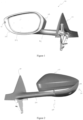
Figure 1 is a rear perspective view of a lamp assembly integrated into an exterior rear view mirror assembly according to an embodiment of the invention; -
Figure 2 is a front perspective view of the assembly ofFigure 1 ; -
Figure 3 is a side perspective view of the assembly ofFigure 1 ; -
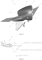
Figure 4 is a cross sectional view of the lamp assembly including the minimum horizontal angle of light distribution in space to be provided by the compliance light; -
Figure 5 is a front perspective view of the lamp assembly with its outer lens removed; -
Figure 6 is a detailed front perspective view of the lamp assembly ofFigure 5 ; -
Figure 7 is a front perspective view of the lamp assembly offigure 5 including the outer lens; -
Figure 8 is a rear perspective view of the lamp assembly ofFigure 7 ; -
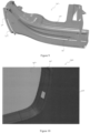
Figure 9 is a rear perspective view of the outer lens; and -
Figure 10 is a rear perspective view of a lamp assembly integrated into an exterior rear view mirror assembly according to an alternative embodiment of the invention. - Referring to
Figures 1 to 3 , there is shown alamp assembly 200 integrated into an exterior rearview mirror assembly 100. The mirror assembly comprises avehicle mounting portion 101 for mounting the assembly to the side of a vehicle, and abase frame 102 in connection with thevehicle mounting portion 101 for supporting the remainder of themirror assembly 100. Thelamp assembly 200 is supported by thebase frame 102, and is enclosed by anouter case 103, which also houses therear view mirror 104 andmirror surround 105. - The
lamp assembly 200 provides a cosmetic light configured to provide light output generally forward of the vehicle. Thelamp assembly 200 also provides a compliance light configured to provide light output to an area required by law. - Referring now to
Figure 4 , where there is shown a schematic top view of the minimum horizontal angle of light distribution in space to be provided by the compliance light, as required by Australian Design Rule 6/00 - Direction Indicators. It can be seen that the light output is required to be provided in a minimum 5 degree arc offset 5 degrees from a line parallel to the vehicle centreline. In this embodiment, the compliance light is configured to comply with these requirements. - Referring now to
Figures 5 and 6 , where there is shown thelamp assembly 200, with its outer lens removed to show thelamp housing 201 and compliancelight guide 211. In one embodiment, thehousing 201 and compliancelight guide 211 are formed in a two shot injection moulding process. First, thehousing 201 is moulded from black acrylonitrile butadiene styrene (ABS) or other suitable opaque substrate, then the compliancelight guide 211 is overmoulded using an acrylic (PMMA) or other suitable clear or transparent substrate. - In an alternative embodiment, the
lamp housing 201 and compliancelight guide 211 may instead be separate components welded together. - The
lamp housing 201 supports and houses an elongate cosmeticlight pipe 206, with an elongate light emitting surface 206a, thelight pipe 206 being illuminated at its first and second ends by a first end PCB 207 andlight source 208 and a second end PCB 209 andlight source 210 respectively. Thelamp housing 201 also supports and houses aPCB 216 andlight source 217 for illuminating the compliancelight guide 211. - In one embodiment, the
light sources - The
cosmetic light pipe 206 is manufactured from a clear plastic (such as PMMA) and is adapted to be substantially transparent when in an un-lit state while being diffusive in a lit-state. When lit, light exits the light emitting surface 206a of thecosmetic light pipe 206 with substantially uniform luminous intensity along its length. This may be achieved by using surface optics along its length to distribute the light evenly along its length. Alternatively, thecosmetic light pipe 206 may be filled with light scattering particles, where most light rays that enter thelight pipe 206 will encounter the light scattering particles that alter the direction of the rays. The effect of this light scattering is that light rays will spread throughout thelight pipe 206, such that an even distribution of light output from the light emitting surface 206a occurs. - The light scattering particles may be titanium dioxide particles of sufficient size and concentration such that the
light pipe 206 appears transparent when un-lit while providing a substantially uniform luminous intensity surface output when lit. - As can be seen more clearly in
Figure 6 , thelight source 217 is immediately adjacent the light receiving surface 212 of the compliancelight guide 211, such that light emitted from the light source is received by the light receiving surface 212 of thelight guide 211, passes through the mid-section 213 and is directed toward thelight emitting surface 214 of thelight guide 211, such that light is output from thelight guide 211 such that at least the minimum horizontal angle of light distribution in space is achieved. - In one embodiment, the
light emitting surface 214 may have surface optics present to diffuse light output from the light emitting surface. In a further embodiment, thelight guide 211 may be configured such that light is output from thelight guide 211 with a substantially uniform luminance. - Referring now to
Figures 7 and 8 , where there is shown thelamp assembly 200, including theouter lens 202. Theouter lens 202 is formed in a two shot injection moulding process, comprising an opaqueinner portion 203 and a light transmissiveouter portion 205. As best shown inFigure 9 , the opaqueinner portion 203 has an elongate opening 204 to allow light emitted from the adjacent light emitting surface 206a of thelight pipe 206 to transmit through the light transmissiveouter portion 205. The opaqueinner portion 203 is manufactured from an opaque plastic (such as ABS), and the light transmissiveouter portion 205 is manufactured from a clear or tinted plastic (such as PMMA). - In alternative embodiments, the
outer lens 202 may be a single component having an opaque coating on an inner surface formed by example by applying paint or a thin film coating. Thelight transmissive window 203 may be formed by etching away the opaque coating or masking the area before coating. - The
outer lens 202 and housing 201 (including the overmoulded compliance light guide 211) are welded together using hot plate welding and as best shown inFigure 7 , define a sealed, weatherproof enclosure housing the cosmetic light pipe 21,PCBs 207, 209, 216 andlight sources - As best shown in
Figures 2 and3 , the exterior rearview mirror assembly 100 is configured such that the light receiving surface 212 of the compliancelight guide 211 is within the enclosure, and the light emitting surface of the compliancelight guide 211 is outside the enclosure, such that the only externally visible components of thelamp assembly 200 are theouter lens 202 and thelight emitting surface 214 of the compliancelight guide 211. It will be appreciated that the co-moulding or welding of the compliancelight guide 211 to thehousing 201 allows for it to be an external feature, while the enclosure remains fully sealed. - As best seen in
Figure 5 , the compliancelight guide 211 features a mid-section 213 with a reduced cross sectional area. As shown inFigure 9 , theouter lens 202 features a complementary cut out 218, wherein when theouter lens 202 is welded to thelamp housing 201 and compliancelight guide 211 to form the sealed enclosure, the mid-section 213 nests within the cut out 218. Themirror surround 105 has a similar cut out (not shown) which also encloses the mid-section 213. such that the only visible component of the compliance light guide is thelight emitting surface 214. - Referring now to
Figure 10 , where there is shown a rear perspective view of an exterior rear view mirror assembly 300 according to an alternative embodiment. This embodiment includes the additional feature of a compliance light guide with a secondlight emitting surface 303 which is directed toward the driver of the vehicle and employed as a tell tale light to notify the driver that the compliance light is illuminated.
Claims (9)
- A lamp assembly (200) adapted to be integrated into an exterior rear view mirror assembly (100) for a vehicle including:- a housing (201);- an outer lens (202) partially covering the housing (201) to define an enclosure between the housing (201) and lens (202);- a light emitting diode (LED) light source (217) arranged in the enclosure; and- a light guide (211) forming part of the housing (201), the light guide (211) having a light receiving surface (212) within the enclosure and a light emitting surface (214) outside the enclosure, such that light emitted from the LED light source (217) is received by the light receiving surface (212) of the light guide (211) and directed toward the light emitting surface (214) of the light guide (211), such that light is output from the light guide (211),wherein the lamp assembly (200) provides a cosmetic light configured to provide light output generally forward of the vehicle and a compliance light configured to provide light output over a viewing angle of at least 55 degrees in a plane, with the light guide (211) being a compliance light guide (211) featuring a mid-section (213) with a reduced cross sectional area, andcharacterized in thatthe outer lens (202) includes an opaque inner portion (203) and a light transmissive outer portion (205), wherein the opaque inner portion (203) includes an elongate opening (204) to allow light to transmit through the outer portion (205) with an elongated cosmetic light pipe (206), which is further included in the lamp assembly (200) for guiding light from at least one light source (208) to an elongate light emitting surface (206a) being housed within the enclosure such that the light emitting surface (206a) of the light pipe (206) is adjacent to the elongate opening (204) of the inner portion, andthe outer lens (202) features a cut out (218) complementary to the mid-section (213) of the compliance light guide (211), wherein when the outer lens (202) is welded to the housing (201) and compliance light guide (211) to form a sealed enclosure, the mid-section (213) nests within the cut out (218), wherein the lamp enclosure is weatherproof.
- The lamp assembly (200) as claimed in claim 1, wherein the light is output from the light guide (211) with a substantially uniform luminance.
- The lamp assembly (200) as claimed in any of the preceding claims, wherein the plane is a horizontal plane.
- The lamp assembly (200) of any of the preceding claims, wherein the light emitting surface (214) of the light guide (211) includes surface optics to diffuse light output from the light emitting surface (214).
- The lamp assembly (200) of any of the preceding claims, wherein the housing (201),
excepting the light guide (211) forming part of the housing (201), is opaque. - The lamp assembly (200) of any of the preceding claims, wherein the light guide (211) is clear.
- The lamp assembly (200) of any of the preceding claims, wherein the elongated light pipe (206) has a substantially uniform luminous intensity along its length.
- The lamp assembly (200) of claim 7, wherein the substantially uniform luminous intensity along its length is achieved by- using surface optics along its length to distribute the light evenly along its length, or- the light pipe (206) being filled with light scattering particles, where most light rays that enter the light pipe (206) will encounter the light scattering particles that alter the direction of light rays, where this light scattering is that light rays are spread throughout the light pipe (206) such that an even distribution of light output from the light emitting surface (206a) occurs.
- The lamp assembly (200) of any of the preceding claims, wherein the elongated light pipe (206) being illuminated at its first and second ends by a first end PCB (207) and light source (208) and a second end PCB (209) and another light source (210).
Applications Claiming Priority (2)
| Application Number | Priority Date | Filing Date | Title |
|---|---|---|---|
| AU2016902106A AU2016902106A0 (en) | 2016-06-01 | A lamp assembly for a vehicle | |
| PCT/EP2017/063034 WO2017207567A1 (en) | 2016-06-01 | 2017-05-30 | A lamp assembly for a vehicle |
Publications (2)
| Publication Number | Publication Date |
|---|---|
| EP3463980A1 EP3463980A1 (en) | 2019-04-10 |
| EP3463980B1 true EP3463980B1 (en) | 2023-05-03 |
Family
ID=58873820
Family Applications (1)
| Application Number | Title | Priority Date | Filing Date |
|---|---|---|---|
| EP17726933.9A Active EP3463980B1 (en) | 2016-06-01 | 2017-05-30 | A lamp assembly for a vehicle |
Country Status (4)
| Country | Link |
|---|---|
| US (1) | US10920955B2 (en) |
| EP (1) | EP3463980B1 (en) |
| CN (1) | CN109844403B (en) |
| WO (1) | WO2017207567A1 (en) |
Families Citing this family (6)
| Publication number | Priority date | Publication date | Assignee | Title |
|---|---|---|---|---|
| CN108488755A (en) * | 2018-05-14 | 2018-09-04 | 华域视觉科技(上海)有限公司 | A kind of combination optical system of total reflection for automobile lamp |
| DE102019209780A1 (en) * | 2019-07-03 | 2021-01-07 | Bayerische Motoren Werke Aktiengesellschaft | Method for manufacturing a blinker device by means of an injection molding process, blinker device, side mirror and motor vehicle |
| JP7666892B2 (en) * | 2019-12-18 | 2025-04-22 | 株式会社村上開明堂 | BSM unit |
| EP4215414A1 (en) * | 2022-01-24 | 2023-07-26 | Ficomirrors, S.A. | Indirect vision device |
| DE102022128892A1 (en) * | 2022-11-01 | 2024-05-02 | Motherson Innovations Company Limited | Lighting device, rear-view device and motor vehicle |
| US11933471B1 (en) | 2023-02-02 | 2024-03-19 | Ford Global Technologies, Llc | Vehicle lighting assembly with covered light blade and lighting method |
Citations (3)
| Publication number | Priority date | Publication date | Assignee | Title |
|---|---|---|---|---|
| EP1914118A2 (en) * | 2006-10-06 | 2008-04-23 | Visiocorp Patents S.à.r.l. | External rear mirror with illumination device |
| US20110170307A1 (en) * | 2010-01-14 | 2011-07-14 | Koito Manufacturing Co., Ltd. | Vehicle lamp |
| EP2746106A1 (en) * | 2011-08-08 | 2014-06-25 | Fu-se Vacuum Forming Co., Ltd. | Vehicle functional component |
Family Cites Families (11)
| Publication number | Priority date | Publication date | Assignee | Title |
|---|---|---|---|---|
| DE102005013682B4 (en) * | 2005-03-18 | 2010-07-08 | SMR Patents S.à.r.l. | Exterior rearview mirror of vehicles, preferably motor vehicles |
| JP5032163B2 (en) * | 2007-03-12 | 2012-09-26 | 株式会社ミツバ | Vehicle lamp |
| JP5209266B2 (en) * | 2007-10-18 | 2013-06-12 | 株式会社ミツバ | door mirror |
| ES2335332B1 (en) * | 2008-01-16 | 2011-01-07 | Alejandro Rodriguez Barros | ASSEMBLY OF MULTISEÑAL EXTERIOR REAR VIEW MIRROR OF A VEHICLE. |
| JP5007362B2 (en) * | 2008-03-03 | 2012-08-22 | 株式会社フジクラ | Door mirror device |
| JP6251189B2 (en) * | 2012-01-24 | 2017-12-20 | エスエムアール・パテンツ・ソシエテ・ア・レスポンサビリテ・リミテ | Reflective coating based on chromium |
| DE102012211821B4 (en) * | 2012-07-06 | 2019-09-05 | Magna Mirrors Holding Gmbh | Luminaire unit for a motor vehicle, in which lamps are arranged in a housing shell with window portion |
| EP2774814A1 (en) * | 2013-03-08 | 2014-09-10 | Flextronics Automotive GmbH & Co. KG | Mirror flashing light for an exterior rear view mirror |
| EP2803532B1 (en) * | 2013-05-17 | 2017-11-01 | Fico Mirrors S.A. | Mirror device for motor vehicles |
| JP6326963B2 (en) * | 2014-05-22 | 2018-05-23 | 市光工業株式会社 | Vehicle light guide member, vehicle lamp |
| EP3741619B1 (en) * | 2016-01-11 | 2025-05-28 | SMR Patents S.à.r.l. | An elongate illuminated automotive design element |
-
2017
- 2017-05-30 EP EP17726933.9A patent/EP3463980B1/en active Active
- 2017-05-30 WO PCT/EP2017/063034 patent/WO2017207567A1/en not_active Ceased
- 2017-05-30 CN CN201780033082.1A patent/CN109844403B/en active Active
-
2018
- 2018-11-29 US US16/204,565 patent/US10920955B2/en active Active
Patent Citations (3)
| Publication number | Priority date | Publication date | Assignee | Title |
|---|---|---|---|---|
| EP1914118A2 (en) * | 2006-10-06 | 2008-04-23 | Visiocorp Patents S.à.r.l. | External rear mirror with illumination device |
| US20110170307A1 (en) * | 2010-01-14 | 2011-07-14 | Koito Manufacturing Co., Ltd. | Vehicle lamp |
| EP2746106A1 (en) * | 2011-08-08 | 2014-06-25 | Fu-se Vacuum Forming Co., Ltd. | Vehicle functional component |
Also Published As
| Publication number | Publication date |
|---|---|
| CN109844403B (en) | 2021-06-11 |
| US10920955B2 (en) | 2021-02-16 |
| EP3463980A1 (en) | 2019-04-10 |
| US20190093849A1 (en) | 2019-03-28 |
| CN109844403A (en) | 2019-06-04 |
| WO2017207567A1 (en) | 2017-12-07 |
Similar Documents
| Publication | Publication Date | Title |
|---|---|---|
| EP2990720B1 (en) | Vehicle lighting unit | |
| EP2681485B1 (en) | Automotive lighting unit | |
| US10184635B2 (en) | Light device | |
| KR101684117B1 (en) | Mood lamp for vehicle | |
| KR102565730B1 (en) | Motor vehicle lighting device | |
| US20080089080A1 (en) | Door mirror with turn lamp | |
| JP4735852B2 (en) | Vehicle headlamp | |
| US8599037B2 (en) | Door mirror for an automobile | |
| US9541703B2 (en) | Lamp | |
| US20200158309A1 (en) | Lamp and vehicle having same | |
| CN103153702A (en) | Signalling lamps for motor vehicle | |
| CN109844403B (en) | Lamp assembly for vehicle | |
| US8277062B2 (en) | Lamp assembly and housing therefor | |
| JP2017027823A (en) | Vehicular rear combination lamp | |
| WO2020224081A1 (en) | Lane change blind area warning lamp | |
| CN108224351A (en) | Lighting unit | |
| JP2015008111A (en) | Composite lamp unit using linear light guide body, and vehicular lighting device | |
| KR20180099154A (en) | Interior illumination lamp unit for vehicle and method for manufacturing the same | |
| CN100537300C (en) | Automotive headlight assembly with one main light source and one driving direction indicator | |
| JP5363179B2 (en) | Vehicle lighting | |
| JP2013193642A (en) | Vehicle combination lamp | |
| CN117957400A (en) | Vehicle lighting | |
| JP2009113644A (en) | Side turn lamp device for door mirror | |
| EP3825602B1 (en) | Automotive lighting and/or signaling device | |
| JP2013178995A (en) | Vehicular lamp |
Legal Events
| Date | Code | Title | Description |
|---|---|---|---|
| STAA | Information on the status of an ep patent application or granted ep patent |
Free format text: STATUS: UNKNOWN |
|
| STAA | Information on the status of an ep patent application or granted ep patent |
Free format text: STATUS: THE INTERNATIONAL PUBLICATION HAS BEEN MADE |
|
| PUAI | Public reference made under article 153(3) epc to a published international application that has entered the european phase |
Free format text: ORIGINAL CODE: 0009012 |
|
| STAA | Information on the status of an ep patent application or granted ep patent |
Free format text: STATUS: REQUEST FOR EXAMINATION WAS MADE |
|
| 17P | Request for examination filed |
Effective date: 20181121 |
|
| AK | Designated contracting states |
Kind code of ref document: A1 Designated state(s): AL AT BE BG CH CY CZ DE DK EE ES FI FR GB GR HR HU IE IS IT LI LT LU LV MC MK MT NL NO PL PT RO RS SE SI SK SM TR |
|
| AX | Request for extension of the european patent |
Extension state: BA ME |
|
| RIN1 | Information on inventor provided before grant (corrected) |
Inventor name: BELCHER, SIMON Inventor name: DICKSON, JAY |
|
| DAV | Request for validation of the european patent (deleted) | ||
| DAX | Request for extension of the european patent (deleted) | ||
| STAA | Information on the status of an ep patent application or granted ep patent |
Free format text: STATUS: EXAMINATION IS IN PROGRESS |
|
| 17Q | First examination report despatched |
Effective date: 20201116 |
|
| RIC1 | Information provided on ipc code assigned before grant |
Ipc: F21S 43/27 20180101ALI20221012BHEP Ipc: F21S 43/237 20180101ALI20221012BHEP Ipc: F21S 43/14 20180101ALI20221012BHEP Ipc: B60R 1/12 20060101ALI20221012BHEP Ipc: B60Q 1/26 20060101AFI20221012BHEP |
|
| GRAP | Despatch of communication of intention to grant a patent |
Free format text: ORIGINAL CODE: EPIDOSNIGR1 |
|
| STAA | Information on the status of an ep patent application or granted ep patent |
Free format text: STATUS: GRANT OF PATENT IS INTENDED |
|
| INTG | Intention to grant announced |
Effective date: 20221125 |
|
| GRAS | Grant fee paid |
Free format text: ORIGINAL CODE: EPIDOSNIGR3 |
|
| GRAA | (expected) grant |
Free format text: ORIGINAL CODE: 0009210 |
|
| STAA | Information on the status of an ep patent application or granted ep patent |
Free format text: STATUS: THE PATENT HAS BEEN GRANTED |
|
| AK | Designated contracting states |
Kind code of ref document: B1 Designated state(s): AL AT BE BG CH CY CZ DE DK EE ES FI FR GB GR HR HU IE IS IT LI LT LU LV MC MK MT NL NO PL PT RO RS SE SI SK SM TR |
|
| REG | Reference to a national code |
Ref country code: GB Ref legal event code: FG4D |
|
| REG | Reference to a national code |
Ref country code: DE Ref legal event code: R096 Ref document number: 602017068302 Country of ref document: DE |
|
| REG | Reference to a national code |
Ref country code: AT Ref legal event code: REF Ref document number: 1564325 Country of ref document: AT Kind code of ref document: T Effective date: 20230515 Ref country code: CH Ref legal event code: EP |
|
| REG | Reference to a national code |
Ref country code: IE Ref legal event code: FG4D |
|
| P01 | Opt-out of the competence of the unified patent court (upc) registered |
Effective date: 20230616 |
|
| REG | Reference to a national code |
Ref country code: LT Ref legal event code: MG9D |
|
| REG | Reference to a national code |
Ref country code: NL Ref legal event code: MP Effective date: 20230503 |
|
| REG | Reference to a national code |
Ref country code: AT Ref legal event code: MK05 Ref document number: 1564325 Country of ref document: AT Kind code of ref document: T Effective date: 20230503 |
|
| PG25 | Lapsed in a contracting state [announced via postgrant information from national office to epo] |
Ref country code: SE Free format text: LAPSE BECAUSE OF FAILURE TO SUBMIT A TRANSLATION OF THE DESCRIPTION OR TO PAY THE FEE WITHIN THE PRESCRIBED TIME-LIMIT Effective date: 20230503 Ref country code: PT Free format text: LAPSE BECAUSE OF FAILURE TO SUBMIT A TRANSLATION OF THE DESCRIPTION OR TO PAY THE FEE WITHIN THE PRESCRIBED TIME-LIMIT Effective date: 20230904 Ref country code: NO Free format text: LAPSE BECAUSE OF FAILURE TO SUBMIT A TRANSLATION OF THE DESCRIPTION OR TO PAY THE FEE WITHIN THE PRESCRIBED TIME-LIMIT Effective date: 20230803 Ref country code: NL Free format text: LAPSE BECAUSE OF FAILURE TO SUBMIT A TRANSLATION OF THE DESCRIPTION OR TO PAY THE FEE WITHIN THE PRESCRIBED TIME-LIMIT Effective date: 20230503 Ref country code: ES Free format text: LAPSE BECAUSE OF FAILURE TO SUBMIT A TRANSLATION OF THE DESCRIPTION OR TO PAY THE FEE WITHIN THE PRESCRIBED TIME-LIMIT Effective date: 20230503 Ref country code: AT Free format text: LAPSE BECAUSE OF FAILURE TO SUBMIT A TRANSLATION OF THE DESCRIPTION OR TO PAY THE FEE WITHIN THE PRESCRIBED TIME-LIMIT Effective date: 20230503 |
|
| PG25 | Lapsed in a contracting state [announced via postgrant information from national office to epo] |
Ref country code: RS Free format text: LAPSE BECAUSE OF FAILURE TO SUBMIT A TRANSLATION OF THE DESCRIPTION OR TO PAY THE FEE WITHIN THE PRESCRIBED TIME-LIMIT Effective date: 20230503 Ref country code: PL Free format text: LAPSE BECAUSE OF FAILURE TO SUBMIT A TRANSLATION OF THE DESCRIPTION OR TO PAY THE FEE WITHIN THE PRESCRIBED TIME-LIMIT Effective date: 20230503 Ref country code: LV Free format text: LAPSE BECAUSE OF FAILURE TO SUBMIT A TRANSLATION OF THE DESCRIPTION OR TO PAY THE FEE WITHIN THE PRESCRIBED TIME-LIMIT Effective date: 20230503 Ref country code: LT Free format text: LAPSE BECAUSE OF FAILURE TO SUBMIT A TRANSLATION OF THE DESCRIPTION OR TO PAY THE FEE WITHIN THE PRESCRIBED TIME-LIMIT Effective date: 20230503 Ref country code: IS Free format text: LAPSE BECAUSE OF FAILURE TO SUBMIT A TRANSLATION OF THE DESCRIPTION OR TO PAY THE FEE WITHIN THE PRESCRIBED TIME-LIMIT Effective date: 20230903 Ref country code: HR Free format text: LAPSE BECAUSE OF FAILURE TO SUBMIT A TRANSLATION OF THE DESCRIPTION OR TO PAY THE FEE WITHIN THE PRESCRIBED TIME-LIMIT Effective date: 20230503 Ref country code: GR Free format text: LAPSE BECAUSE OF FAILURE TO SUBMIT A TRANSLATION OF THE DESCRIPTION OR TO PAY THE FEE WITHIN THE PRESCRIBED TIME-LIMIT Effective date: 20230804 |
|
| PG25 | Lapsed in a contracting state [announced via postgrant information from national office to epo] |
Ref country code: FI Free format text: LAPSE BECAUSE OF FAILURE TO SUBMIT A TRANSLATION OF THE DESCRIPTION OR TO PAY THE FEE WITHIN THE PRESCRIBED TIME-LIMIT Effective date: 20230503 |
|
| REG | Reference to a national code |
Ref country code: CH Ref legal event code: PL |
|
| PG25 | Lapsed in a contracting state [announced via postgrant information from national office to epo] |
Ref country code: SK Free format text: LAPSE BECAUSE OF FAILURE TO SUBMIT A TRANSLATION OF THE DESCRIPTION OR TO PAY THE FEE WITHIN THE PRESCRIBED TIME-LIMIT Effective date: 20230503 |
|
| REG | Reference to a national code |
Ref country code: BE Ref legal event code: MM Effective date: 20230531 |
|
| PG25 | Lapsed in a contracting state [announced via postgrant information from national office to epo] |
Ref country code: SM Free format text: LAPSE BECAUSE OF FAILURE TO SUBMIT A TRANSLATION OF THE DESCRIPTION OR TO PAY THE FEE WITHIN THE PRESCRIBED TIME-LIMIT Effective date: 20230503 Ref country code: SK Free format text: LAPSE BECAUSE OF FAILURE TO SUBMIT A TRANSLATION OF THE DESCRIPTION OR TO PAY THE FEE WITHIN THE PRESCRIBED TIME-LIMIT Effective date: 20230503 Ref country code: RO Free format text: LAPSE BECAUSE OF FAILURE TO SUBMIT A TRANSLATION OF THE DESCRIPTION OR TO PAY THE FEE WITHIN THE PRESCRIBED TIME-LIMIT Effective date: 20230503 Ref country code: LU Free format text: LAPSE BECAUSE OF NON-PAYMENT OF DUE FEES Effective date: 20230530 Ref country code: LI Free format text: LAPSE BECAUSE OF NON-PAYMENT OF DUE FEES Effective date: 20230531 Ref country code: EE Free format text: LAPSE BECAUSE OF FAILURE TO SUBMIT A TRANSLATION OF THE DESCRIPTION OR TO PAY THE FEE WITHIN THE PRESCRIBED TIME-LIMIT Effective date: 20230503 Ref country code: DK Free format text: LAPSE BECAUSE OF FAILURE TO SUBMIT A TRANSLATION OF THE DESCRIPTION OR TO PAY THE FEE WITHIN THE PRESCRIBED TIME-LIMIT Effective date: 20230503 Ref country code: CZ Free format text: LAPSE BECAUSE OF FAILURE TO SUBMIT A TRANSLATION OF THE DESCRIPTION OR TO PAY THE FEE WITHIN THE PRESCRIBED TIME-LIMIT Effective date: 20230503 Ref country code: CH Free format text: LAPSE BECAUSE OF NON-PAYMENT OF DUE FEES Effective date: 20230531 |
|
| REG | Reference to a national code |
Ref country code: DE Ref legal event code: R097 Ref document number: 602017068302 Country of ref document: DE |
|
| PG25 | Lapsed in a contracting state [announced via postgrant information from national office to epo] |
Ref country code: MC Free format text: LAPSE BECAUSE OF FAILURE TO SUBMIT A TRANSLATION OF THE DESCRIPTION OR TO PAY THE FEE WITHIN THE PRESCRIBED TIME-LIMIT Effective date: 20230503 |
|
| REG | Reference to a national code |
Ref country code: IE Ref legal event code: MM4A |
|
| PG25 | Lapsed in a contracting state [announced via postgrant information from national office to epo] |
Ref country code: MC Free format text: LAPSE BECAUSE OF FAILURE TO SUBMIT A TRANSLATION OF THE DESCRIPTION OR TO PAY THE FEE WITHIN THE PRESCRIBED TIME-LIMIT Effective date: 20230503 |
|
| PLBE | No opposition filed within time limit |
Free format text: ORIGINAL CODE: 0009261 |
|
| STAA | Information on the status of an ep patent application or granted ep patent |
Free format text: STATUS: NO OPPOSITION FILED WITHIN TIME LIMIT |
|
| REG | Reference to a national code |
Ref country code: DE Ref legal event code: R084 Ref document number: 602017068302 Country of ref document: DE |
|
| 26N | No opposition filed |
Effective date: 20240206 |
|
| PG25 | Lapsed in a contracting state [announced via postgrant information from national office to epo] |
Ref country code: IE Free format text: LAPSE BECAUSE OF NON-PAYMENT OF DUE FEES Effective date: 20230530 |
|
| PG25 | Lapsed in a contracting state [announced via postgrant information from national office to epo] |
Ref country code: IE Free format text: LAPSE BECAUSE OF NON-PAYMENT OF DUE FEES Effective date: 20230530 |
|
| PG25 | Lapsed in a contracting state [announced via postgrant information from national office to epo] |
Ref country code: SI Free format text: LAPSE BECAUSE OF FAILURE TO SUBMIT A TRANSLATION OF THE DESCRIPTION OR TO PAY THE FEE WITHIN THE PRESCRIBED TIME-LIMIT Effective date: 20230503 |
|
| PG25 | Lapsed in a contracting state [announced via postgrant information from national office to epo] |
Ref country code: SI Free format text: LAPSE BECAUSE OF FAILURE TO SUBMIT A TRANSLATION OF THE DESCRIPTION OR TO PAY THE FEE WITHIN THE PRESCRIBED TIME-LIMIT Effective date: 20230503 Ref country code: IT Free format text: LAPSE BECAUSE OF FAILURE TO SUBMIT A TRANSLATION OF THE DESCRIPTION OR TO PAY THE FEE WITHIN THE PRESCRIBED TIME-LIMIT Effective date: 20230503 Ref country code: BE Free format text: LAPSE BECAUSE OF NON-PAYMENT OF DUE FEES Effective date: 20230531 |
|
| PG25 | Lapsed in a contracting state [announced via postgrant information from national office to epo] |
Ref country code: BG Free format text: LAPSE BECAUSE OF FAILURE TO SUBMIT A TRANSLATION OF THE DESCRIPTION OR TO PAY THE FEE WITHIN THE PRESCRIBED TIME-LIMIT Effective date: 20230503 |
|
| PG25 | Lapsed in a contracting state [announced via postgrant information from national office to epo] |
Ref country code: BG Free format text: LAPSE BECAUSE OF FAILURE TO SUBMIT A TRANSLATION OF THE DESCRIPTION OR TO PAY THE FEE WITHIN THE PRESCRIBED TIME-LIMIT Effective date: 20230503 |
|
| PGFP | Annual fee paid to national office [announced via postgrant information from national office to epo] |
Ref country code: DE Payment date: 20250519 Year of fee payment: 9 |
|
| PGFP | Annual fee paid to national office [announced via postgrant information from national office to epo] |
Ref country code: FR Payment date: 20250523 Year of fee payment: 9 |
|
| PG25 | Lapsed in a contracting state [announced via postgrant information from national office to epo] |
Ref country code: CY Free format text: LAPSE BECAUSE OF FAILURE TO SUBMIT A TRANSLATION OF THE DESCRIPTION OR TO PAY THE FEE WITHIN THE PRESCRIBED TIME-LIMIT; INVALID AB INITIO Effective date: 20170530 |
|
| PG25 | Lapsed in a contracting state [announced via postgrant information from national office to epo] |
Ref country code: HU Free format text: LAPSE BECAUSE OF FAILURE TO SUBMIT A TRANSLATION OF THE DESCRIPTION OR TO PAY THE FEE WITHIN THE PRESCRIBED TIME-LIMIT; INVALID AB INITIO Effective date: 20170530 |
|
| PG25 | Lapsed in a contracting state [announced via postgrant information from national office to epo] |
Ref country code: TR Free format text: LAPSE BECAUSE OF FAILURE TO SUBMIT A TRANSLATION OF THE DESCRIPTION OR TO PAY THE FEE WITHIN THE PRESCRIBED TIME-LIMIT Effective date: 20230503 |
|
| PGFP | Annual fee paid to national office [announced via postgrant information from national office to epo] |
Ref country code: GB Payment date: 20260324 Year of fee payment: 10 |