EP3463840B1 - Method for pressing a workpiece with a predetermined pressing force - Google Patents
Method for pressing a workpiece with a predetermined pressing force Download PDFInfo
- Publication number
- EP3463840B1 EP3463840B1 EP17739846.8A EP17739846A EP3463840B1 EP 3463840 B1 EP3463840 B1 EP 3463840B1 EP 17739846 A EP17739846 A EP 17739846A EP 3463840 B1 EP3463840 B1 EP 3463840B1
- Authority
- EP
- European Patent Office
- Prior art keywords
- pressing force
- electric motor
- forming tool
- measuring unit
- rotational speed
- Prior art date
- Legal status (The legal status is an assumption and is not a legal conclusion. Google has not performed a legal analysis and makes no representation as to the accuracy of the status listed.)
- Active
Links
Images


Classifications
-
- B—PERFORMING OPERATIONS; TRANSPORTING
- B30—PRESSES
- B30B—PRESSES IN GENERAL
- B30B15/00—Details of, or accessories for, presses; Auxiliary measures in connection with pressing
- B30B15/14—Control arrangements for mechanically-driven presses
- B30B15/148—Electrical control arrangements
-
- B—PERFORMING OPERATIONS; TRANSPORTING
- B30—PRESSES
- B30B—PRESSES IN GENERAL
- B30B1/00—Presses, using a press ram, characterised by the features of the drive therefor, pressure being transmitted directly, or through simple thrust or tension members only, to the press ram or platen
- B30B1/18—Presses, using a press ram, characterised by the features of the drive therefor, pressure being transmitted directly, or through simple thrust or tension members only, to the press ram or platen by screw means
- B30B1/181—Presses, using a press ram, characterised by the features of the drive therefor, pressure being transmitted directly, or through simple thrust or tension members only, to the press ram or platen by screw means the screw being directly driven by an electric motor
-
- B—PERFORMING OPERATIONS; TRANSPORTING
- B30—PRESSES
- B30B—PRESSES IN GENERAL
- B30B15/00—Details of, or accessories for, presses; Auxiliary measures in connection with pressing
- B30B15/14—Control arrangements for mechanically-driven presses
-
- B—PERFORMING OPERATIONS; TRANSPORTING
- B30—PRESSES
- B30B—PRESSES IN GENERAL
- B30B15/00—Details of, or accessories for, presses; Auxiliary measures in connection with pressing
- B30B15/16—Control arrangements for fluid-driven presses
- B30B15/18—Control arrangements for fluid-driven presses controlling the reciprocating motion of the ram
- B30B15/186—Controlling the return movement of the ram, e.g. decompression valves
-
- B—PERFORMING OPERATIONS; TRANSPORTING
- B30—PRESSES
- B30B—PRESSES IN GENERAL
- B30B15/00—Details of, or accessories for, presses; Auxiliary measures in connection with pressing
- B30B15/26—Programme control arrangements
Definitions
- the invention relates to a method for pressing a workpiece with a predetermined pressing force.
- the DE 19606842 A1 discloses a method for pressing a workpiece, wherein a press ram is provided which is coupled to a drive motor by means of a gear. During the pressing process, the drive motor is first accelerated to a maximum speed and then braked to a reduced speed. When the drive motor is operated at the reduced speed, the electrical variables of the drive motor are monitored in order to detect the torque applied to the drive motor.
- the object of the present invention was to overcome the disadvantages of the prior art and to provide a method which has an increased process speed while at the same time maintaining process accuracy.
- An advantage of the method according to the invention is that the method is divided into a wide variety of method steps, the electric motor having a different speed in the individual method steps. This measure ensures that the pressing time can be shortened as much as possible and at the same time the required pressing force can be achieved as precisely as possible.
- the electric motor is operated at a predetermined maximum speed, the forming tool is delivered as quickly as possible.
- the forming tool is moved in the direction of the workpiece, care being taken that the forming tool is freely moved towards the workpiece and the forming tool is not yet in contact with the workpiece. It is only in the subsequent process step in which the electric motor is operated at a reduced speed that the forming tool comes into contact with the workpiece to be machined.
- a spindle drive As an alternative to a spindle drive, another means can also be used which is suitable for converting the rotary movement of the electric motor into a translatory movement of the forming tool.
- the predefined position of the forming tool can be detected, for example, using a linear measuring unit.
- the increase in torque in the electric motor can be detected, for example, by detecting the motor current in the electric motor.
- the electric motor is braked to a predetermined minimum speed.
- the advantage here is that excessive braking and thus the transfer of the pressing force can be prevented by braking the electric motor to minimum speed.
- the electric motor is operated at a minimum speed for a predetermined or predeterminable period of time until vibrations which occur in the drive system from the reduced speed to the minimum speed due to the braking process have largely subsided.
- the advantage here is that by operating the electric motor at the minimum speed in a predetermined period of time it can be achieved that the drive system can swing out and thus there is no falsification of the measured pressing force on the measuring unit. In extreme cases, it may be necessary to select complete standstill as the minimum speed.
- the vibrations that have to decay arise due to the inertia or the inertial forces of the individual components in the drive system and due to the abrupt braking maneuver.
- the control of the electric motor is predetermined by the control on the basis of the pressing force measured in the measuring unit. After this predetermined period of time in which the sensor signal is falsified, it can be switched over to pressing force control in order to be able to achieve the required pressing force.
- the reduced speed is between 0.1% and 100%, in particular between 0.5% and 99%, preferably between 50% and 80% of the maximum speed.
- the further activation of the electric motor predetermined by the control on the basis of the pressing force directly after the detection of the pressing force increase, the electric motor being braked to a predetermined minimum speed after the detection of the pressing force increase and in an initial period during the Braking process, the pressing force recorded in the measuring unit is overlaid by a pressing force based on a model calculation, and after the initial period the pressing force detected by the measuring unit serves as an input variable for the control.
- This alternative variant has the advantage that the process time can be further shortened and optimized. By blending the recorded pressing force with a pressing force based on a minor calculation, the measurement error that occurs due to the oscillation of the system after the braking process of the electric motor can be compensated for.
- the inertia and / or the spring stiffness and / or the damping and the angular or linear accelerations of the individual components installed in the drive train are taken into account in the model calculation.
- the advantage here is that the dynamic behavior of the drive train can be calculated precisely on the basis of these values or on the basis of these state variables, and thereby a falsification of the measured pressing force when braking or accelerating the electric motor can be compensated for.
- the model calculation is adapted on the basis of the respective previous cycles in an iterative learning process, the temporal course of the measured value of the torque in the measuring unit, as well as the motor torque and the associated angle of rotation of the drive shaft in the electric motor being used to adapt the model calculation becomes.
- the advantage here is that the drive method can be adapted and improved during operation, which on the one hand can increase the accuracy to achieve the pressing force and can further shorten the process time.
- a disturbance variable observer in particular a Kalman filter, is used for the model calculation, which is also regulated in the first step and is only blended to the force detected in the measuring unit from a certain point in time.
- a disturbance variable observer can estimate the actual force actually present on the basis of the manipulated variable and the sensor signals, and the estimated external force can be predefined for the control system, which can improve the accuracy when the predetermined pressing force is reached.
- the feedforward controls can be derived using the mathematical models. It may be sufficient to use a highly simplified model, such as a pure rigid body system, which only takes the moments of inertia and no dynamic elements into account. Alternatively, a dynamic system as described in this document can be used for mathematical modeling.
- a piezo sensor is used as the measuring unit, which is arranged in the region of the forming tool for detecting the pressing force.
- the advantage here is that a piezo sensor on the one hand has a high measurement accuracy and, in addition, has a very fast response behavior.
- the further control of the electric motor is predetermined by the control on the basis of a target trajectory of the pressing force value, the speed curve being calculated in a feedforward control from the target trajectory of the pressing force value. If a disturbance variable observer is used, the force actually acting can be estimated. Disruptions can be hidden by fading to this estimated force.
- the pressing force value is estimated by a disturbance variable observer and that in a second phase after the detection of the pressing force increase, the pressing force is detected directly by the measuring unit and serves as an input variable for the control.
- the pressing force value By specifying the pressing force value by means of the disturbance variable observer, vibrations or disturbances in the system can be filtered so that there is no oscillation in the control. After the vibrations have subsided, the torque actually measured on the measuring unit can then serve as an input value for the control.
- the transition between different speeds of the individual method steps is specified in such a way that no sudden increases in the Acceleration occur.
- the jerk that acts on the individual components of the press can be reduced and the longevity of the press can be increased.
- the maximum speed to which the electric motor is accelerated does not necessarily have to correspond to the maximum possible speed of the electric motor. Rather, it is also possible that the maximum speed results from the process parameters and is a calculated value.
- the specified maximum speed can vary from one pressing process to the next.
- a third-order low-pass filter of the form as a controller R F s k FP 1 + s ⁇ Fg 3rd is chosen.
- controller parameters can be set using a loop shaping method.
- the threshold value of the pressing force or the torque which are detected can be a predetermined or individually predeterminable absolute value of the pressing force, for example in N, or the torque, for example in Nm.
- an absolute value of the pressing force or the torque is not specified as the threshold value, but that a predetermined or individually predeterminable increase in the pressing force per travel path of the forming tool (the travel path can be measured directly on the forming tool, or via the Number of revolutions of the drive motor can be calculated) or torque increase per angle of rotation unit of the motor is specified.
- the threshold value of the press force increase can be defined approximately in N per mm of travel or in N per ° angle of rotation of the electric motor.
- the threshold value of the torque increase can be defined in Nm per ° angle of rotation.
- the threshold value is a maximum change in the increase in pressing force per travel path of the forming tool (the Travel distance can be measured directly on the forming tool, or can be calculated from the number of revolutions of the drive motor) or the torque increase per angle of rotation unit of the motor.
- the maximum change in the press force increase per unit of rotation angle can be calculated, for example, by first deriving the function of the press force increase per unit of travel of the forming tool.
- This threshold value for the change in the torque increase can be defined approximately in ⁇ N per ⁇ mm travel.
- the maximum change in the torque increase per unit of rotation angle can be calculated, for example, by the first derivative of the function of the torque increase per unit of rotation of the motor.
- This threshold value of the change in the torque increase can be defined approximately in ⁇ Nm per ⁇ ° angle of rotation.
- a regulation in the sense of this document can be understood as a two-degree of freedom force regulation with a subordinate motor regulation, whereby a control circuit with this regulation can also have additional pilot controls.
- a speed curve is calculated on the basis of the load characteristic and a desired target trajectory for the external pressing force. This speed picks up at the reduced speed and is brought to a standstill. This speed profile ensures that the external pressing force follows the desired target trajectory sufficiently well. This makes it possible to compensate for the remaining control deviation with a linear controller R F. If a disturbance variable observer is used, then the estimated signal is controlled and, at the end of the trajectory, faded over to the measurement signal. If the disturbance variable observer is not available because the quality of the measurement signal is sufficiently good, then the measurement signal is controlled directly and therefore no cross-fading is carried out.
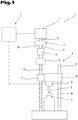
- Fig. 1 shows a schematic representation of a process press 1.
- the process press 1 comprises an electric motor 2, and a forming tool 3 coupled to the electric motor 2.
- the forming tool 3 can act on a workpiece 4 in order to be able to deform it. Such a deformation can be an embossing, for example. Furthermore, it is also conceivable that the workpiece 4 is bent, for example by means of the forming tool 3.
- the forming process of the workpiece 4 can be automated.
- the forming tool 3 can have a wide variety of shapes.
- the electric motor 2 is designed as a servo motor.
- a servo motor can be a synchronous motor, for example.
- the electric motor 2 is connected to a control 5.
- a frequency converter is designed which interacts with the electric motor 2 and specifies the speed of the electric motor 2.
- a spindle drive 6 is coupled to the electric motor 2.
- a spindle drive 6 can be designed, for example, as a screw drive, preferably as a ball screw drive.
- a ball screw has the advantage that it has little play. As a result, high accuracy of the process press 1 can be achieved.
- the rotary drive 6 of the electric motor 2 can be converted into a translatory movement of the forming tool 3 by means of the spindle drive 6.
- a gear 7 is arranged between the spindle drive 6 and the electric motor 2, by means of which the speed of the drive shaft 8 of the electric motor 2 can be reduced.
- a spindle 9 of the spindle drive 6 is coupled to a transmission output shaft 11 arranged on the transmission output 10 and has the same rotational speed as this.
- the spindle 9 of the spindle drive 6 is coupled to the drive shaft 8 of the electric motor 2 and has the same rotational speed as this.
- a measuring unit 12 is arranged between the spindle drive 6 and the forming tool 3 and is designed to detect the pressing force applied to the forming tool 3.
- the measuring unit 12 can be designed in particular as a force sensor or as a load cell. It can preferably be provided that the measuring unit 12 is designed as a piezo sensor.
- the measuring unit 12 is coupled to the control 5.
- a coupling 13 is provided for connecting the electric motor 2 and the gear 6 or for connecting the gear 7 and the spindle drive 6.
- the couplings 13 are used in particular for torque transmission between the individual components and are therefore arranged between the individual components.
- the spindle 9 of the spindle drive 6 is mounted on a bearing 14 which serves to absorb the axial forces and radial forces introduced into the spindle 9. Furthermore, it can be provided that the spindle drive 6 comprises a threaded nut 15, which is coupled to the spindle 9 and converts the rotational movement of the spindle 9 into a translatory movement of the threaded nut 15.
- a slide 16 can be coupled to the threaded nut 15, which can serve to receive the forming tool 3.
- the measuring unit 12 is arranged between the slide 16 and the forming tool 3.
- the measuring unit 12 is integrated in the carriage 16.
- the forming tool 3 is detachably coupled to the slide 16. It can thereby be achieved that different forming tools 3 can be coupled to the slide 16 for different application requirements.
- the carriage 16 is guided on a guide rail 17.
- the forming tool 3 is moved towards the workpiece 4 by means of the spindle drive 6, the spindle drive 6 being driven by the electric motor 2.
- the forming tool 3 is freely moved towards the workpiece 4, it being ensured that the forming tool 3 does not touch the workpiece 4. In other words, one can also speak of a delivery process.
- a pressing surface 18 of the forming tool 3 comes into contact with the workpiece 4, as a result of which the force acting on the forming tool 3 increases suddenly.
- the forming tool 3 is then pressed into the workpiece 4, as a result of which the workpiece 4 is deformed by means of the forming tool 3.
- the pressing process is divided into two stages.
- the first stage is an infeed process in which the forming tool 3 is freely moved towards the workpiece 4 without touching it.
- the second stage is a forming stage, in which the pressing surface 18 of the forming tool 3 bears against the workpiece 4 and the workpiece 4 is deformed by means of the forming tool 3 is, an increased torque must be applied to the drive shaft 8 of the electric motor 2.
- the electric motor 2 is superimposed, speed-controlled, until a predefined pressing force is exceeded or the impact of the forming tool 3 on the workpiece 4 is detected using a gradient method.
- the electric motor 2 In the forming stage, provision can be made for the electric motor 2 to be torque-controlled, with the measured pressing force being used to regulate the electric motor 2.
- a predefined pressing force can be set using a cascaded two degree of freedom control.
- This cascaded control consists of an internal speed control, a superimposed torque control or force control and a corresponding model-based pilot control.
- the pressing force that occurs is compensated for according to the load and the inertia of the drive. If the mechanical coupling between the electric motor 2 and the forming tool 3 is sufficiently stiff, the pressing force recorded on the measuring unit 12 can be used as a direct feedback variable for the torque control or force control.
- the difficulty with the control is to keep the process speed high and to keep the pressing force within predetermined limits. If an ideal, trouble-free route is assumed, an engine speed curve can be found, which makes it possible to set a desired pressing force. In real use, however, faults and measurement noise occurring in the measuring unit 12 are to be expected.
- the aim of the regulation is to regulate the pressing force actually applied to the forming tool in such a way that it reaches a defined value, also referred to as a predetermined pressing force.
- the pressing force actually applied to the forming tool 3 should be measured with the aid of the measuring unit 12 and serve as a feedback variable in the control.
- the pressing force measured in the measuring unit 12 only corresponds to the pressing force actually applied to the forming tool 3 if the forming tool 3 is not being accelerated or braked and therefore no dynamic effects occur due to the inertia of the individual components.
- the pressing force actually applied to the forming tool 3 can be measured precisely by the measuring unit 12 when the forming tool 3 is stationary or moving at a constant feed speed, this state also having to last for a certain period of time, so that vibrations have already subsided.
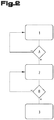
- Fig. 2 shows a flow diagram of a schematic sequence of a first control strategy for pressing the workpiece 4.
- the drive shaft 8 of the electric motor 2 is accelerated to the maximum speed.
- a certain temporal course of the angular velocity or a certain acceleration ramp can be specified on the basis of which the electric motor 2 is accelerated.
- the query A is queried as to whether the drive shaft 8 of the electric motor 2 has already completed a predetermined number of spindle revolutions or, as a result, how far the forming tool 3 has already been moved in its linear movement by means of the spindle drive 6.
- the electric motor 2 is operated at maximum speed until, in query A, reaching the predetermined number of spindle revolutions or reaching the predetermined feed path of the forming tool 3 leads to the condition being met.
- the number of spindle revolutions which serves as a trigger for changing to method step 2 is chosen as high as possible, but chosen so low that in all conceivable cases due to the tolerances it is ensured that the pressing surface 18 of the forming tool 3 is not on the workpiece during this method step 4 concerns.
- method step 1 it can be provided that the pressing force measured on the measuring unit 12 is not queried or at least not included in the engine control.
- the electric motor 2 is then operated at reduced speed in method step 2.
- the reduced speed serves to ensure that there is sufficient time in the measuring unit 12 when an increase in the pressing force is detected in order to reduce the motor speed or to switch over to a force control.
- the speed of rotation in the reduced speed depends on how quickly the electric motor 2 can be braked and which travel path the forming tool 3 can be moved even further after it has been placed on the workpiece 4. This maximum travel distance is also called the offset. If the intended insertion depth is very large, for example, the reduced speed can have a high value and, for example, be approximately the same size as the maximum speed.
- the transition from maximum speed to reduced speed can also take place according to a predetermined temporal profile of the angular speed.
- the measuring unit 12 is activated in order to be able to detect when the pressing surface 18 of the forming tool 3 comes into contact with the workpiece 4, which leads to a sudden increase in the pressing force detected in the measuring unit 12.
- Query B determines whether the pressing force detected in the measuring unit 12 has reached a certain predefined threshold value and method step 3 is initiated when the threshold value is reached.
- Force control is then carried out in method step 3, as shown in the structural diagram of the control loop in Fig. 5 with the controlled system in Fig. 6 is shown activated.
- the electric motor 2 is controlled by means of the force control in such a way that the predetermined pressing force is reached.
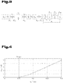
- Fig. 3 shows a structural diagram of the mechanical model of the process press 1. This serves as the basis for the modeling of the process press 1.
- the input variable of the model represents the engine torque M m , which counteracts the friction torque M rm of the drive.
- the motor moment of inertia is determined by ⁇ m .
- the clutch 13 is modeled as a linear spring-mass damper element. This is characterized by the spring constant c k , the damping constant d k and the moment of inertia ⁇ k , half of which is taken into account on the input and output sides.
- M sp The moment after the clutch 13, which acts as the drive torque of the spindle 9, is referred to as M sp .
- the friction losses are taken into account with the moment M rs .
- ⁇ sp the moment of inertia of the spindle 9 is indicated.
- the ball screw transforms the rotational movement of the spindle 9 into a translatory movement of the slide 16.
- the transmission ratio of this transformation is denoted by i g .
- the measuring unit 12, which connects the slide 16 with the mass m 1 and the forming tool 3 with the mass m 2 is modeled with a linear spring-damper model with the spring constant c s and the damping constant ds.
- the position of the carriage 16 is indicated by s 1 and the position of the forming tool 3 by s 2 .
- the transformed spindle torque causes the force F a , which acts on the slide 16.
- the force F s indicates the measured value of the measuring unit 12 and F ext the external force occurring during the pressing.
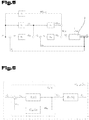
- Fig. 4 shows an exemplary course of the external force over the course of the position of the forming tool 3.
- the exemplary course of the external force can be determined by a test. This exemplary course is also referred to as the load characteristic.
- the load model of the specific use cases is empirical determined.
- the aim is to record a characteristic curve that indicates the relationship between the external force F ext and the position of the forming tool 3 s 2 .
- the forming tool 3 is moved to the workpiece 4 at a constant speed, depending on the application, until a defined limit force is reached.
- the characteristic curve is divided into two areas.
- Fig. 5 shows a structure diagram of a control circuit for force control, the force controller is designed for the forming stage and is active in this.
- the curve of the pressing force has a very steep increase.
- the pressing force rises steeply with only a slight movement of the forming tool 3. It may therefore be necessary for the forming tool 3 to be brought to a standstill within a short distance in order to be able to achieve a predetermined value of the pressing force.
- the dynamics of the underlying speed controller of the electric motor 2 may not be sufficient for this braking maneuver.
- ⁇ m M m ⁇ - F ext i G .
- a replacement model for the controlled system G ⁇ m ⁇ , F s s is in Fig. 6 shown.
- the cut-off frequency ⁇ FG and the gain k FP are adjusted so that a stable behavior is achieved for the closed control loop.
- the controller parameters can be set using a loop shaping process.
- Fig. 7 shows a flow diagram of a schematic sequence of a further control strategy for pressing the workpiece 4, the first two method steps being the same as in the flow diagram below Fig. 2 are.
- the electric motor 2 is operated at a minimum speed.
- the minimum speed can vary from process to process and is specified based on the current process parameters. In extreme cases, it may even be necessary for the minimum speed to be zero or close to zero. Braking from reduced Speed in minimum speed should go as quickly or abruptly as possible within the strength values of process press 1.
- the electric motor 2 is operated at minimum speed until the vibrations occurring in the drive train due to the abrupt braking maneuver have subsided. For this purpose, a pre-calculated period of time for the oscillations to subside is queried in query C.
- the time required to decay the vibrations is not calculated on the basis of a model, but rather that it is adapted in an iterative process or that the vibrations decay by detecting the motor torque in the electric motor 2 in comparison with the measured one Torque is determined in the measuring unit 12.
- Force control is then carried out in method step 4, as shown in the structural diagram of the control loop in Fig. 4 or in the controlled system in Fig. 5 is shown activated.
- the electric motor 2 is controlled by means of the force control in such a way that the predetermined pressing force is reached.
- Fig. 8 serves as the input variable for the force regulator R F not the sensor signal Fs, as shown in Fig. 5 the case is, but an estimated force F ⁇ ext is provided as an input variable for the force regulator R F by a disturbance variable observer 19. Furthermore, a force feedforward control V F , a load feedforward control Vext and an inertia compensation V ⁇ are provided.
- Fig. 9 serves as an input variable for the force regulator R F, a force F ⁇ ext estimated by the disturbance variable observer 19 .
- Force feedforward control V F and inertia compensation V ⁇ are also provided.
- Fig. 10 serves as an input variable for the force regulator R F, a force F ⁇ ext estimated by the disturbance variable observer 19 .
- Force feedforward control V F is also provided.
- Fig. 11 serves as an input variable for the force regulator R F, a force F ⁇ ext estimated by the disturbance variable observer 19 .
- a force feedforward control V F and a load feedforward control Vext are also provided.
- Fig. 12 serves as an input variable for the force controller R F, the sensor signal Fs. Furthermore, a force feedforward control V F , a load feedforward control V ext and an inertia compensation V ⁇ are provided.
- Fig. 13 serves as an input variable for the force controller R F, the sensor signal Fs. Furthermore, a force precontrol V F and an inertia compensation V ⁇ are provided.
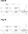
- Fig. 14 serves as an input variable for the force regulator R F, the sensor signal Fs. Furthermore, a force feedforward control V F is provided.
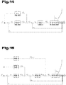
- Fig. 15 serves as an input variable for the force controller R F, the sensor signal Fs. Furthermore, a force feedforward control V F and a load feedforward control V ext are provided.
- All information on value ranges in the objective description should be understood to include any and all sub-areas, e.g. the information 1 to 10 is to be understood in such a way that all sub-areas, starting from the lower limit 1 and the upper limit 10, are included, i.e. all sections start with a lower limit of 1 or greater and end with an upper limit of 10 or less, e.g. 1 to 1.7, or 3.2 to 8.1, or 5.5 to 10.
Description
Die Erfindung betrifft ein Verfahren zum Pressen eines Werkstückes mit einer vorbestimmten Presskraft.The invention relates to a method for pressing a workpiece with a predetermined pressing force.
Aus dem Stand der Technik sind verschiedene Verfahren zum Pressen eines Werkstückes bekannt. Die aus dem Stand der Technik bekannten Verfahren betreffen insbesondere Fertigungsanlagen in welchen Werkstücke mit einer vorbestimmten Presskraft gepresst werden sollen. Dabei müssen die Werkstücke mit einer vorbestimmten Presskraft gepresst werden, wobei der tatsächliche Betrag der Presskraft nur einen geringen Toleranzbereich aufweist.Various methods for pressing a workpiece are known from the prior art. The methods known from the prior art relate in particular to production plants in which workpieces are to be pressed with a predetermined pressing force. The workpieces must be pressed with a predetermined pressing force, the actual amount of the pressing force having only a small tolerance range.
Die
Die aus dem Stand der Technik bekannten Verfahren weisen den Nachteil auf, dass zum Erreichen der geforderten Presskraft unter Einhaltung des geforderten Toleranzbereiches die Pressgeschwindigkeit entsprechend gering gewählt werden muss, um die Presskraft verfälschende dynamische Effekte welche aufgrund der Massenträgheit der einzelnen Bauteile des Antriebsstranges auftreten, hintanzuhalten.The methods known from the prior art have the disadvantage that, in order to achieve the required pressing force while observing the required tolerance range, the pressing speed must be selected to be correspondingly low in order to prevent dynamic effects which distort the pressing force and which occur due to the inertia of the individual components of the drive train .
Aufgabe der vorliegenden Erfindung war es, die Nachteile des Standes der Technik zu überwinden und ein Verfahren zur Verfügung zu stellen, welches eine erhöhte Prozessgeschwindigkeit bei gleichzeitiger Aufrechterhaltung der Prozessgenauigkeit aufweist.The object of the present invention was to overcome the disadvantages of the prior art and to provide a method which has an increased process speed while at the same time maintaining process accuracy.
Diese Aufgabe wird durch eine Vorrichtung und ein Verfahren gemäß Anspruch 1 gelöst.This object is achieved by an apparatus and a method according to
Erfindungsgemäß ist ein Verfahren zum Pressen eines Werkstückes mit einer vorbestimmten Presskraft mittels einem Umformwerkzeug, welches über einen Gewindetrieb mit einem Elektromotor gekoppelt ist, vorgesehen. Ein Gewindetrieb wandelt die rotatorische Bewegung einer Antriebswelle des Elektromotors in eine translatorische Bewegung des Umformwerkzeuges um. Der Elektromotor wird von einer Regelung angesteuert. Das Verfahren umfasst folgende Verfahrensschritte:
- Beschleunigen des Elektromotors in Zudrehrichtung auf eine vorgegebene Maximaldrehzahl, wodurch das Umformwerkzeug auf das Werkstück zubewegt wird;
- Betreiben des Elektromotors in Maximaldrehzahl bis die Antriebswelle des Elektromotors eine vorgegebene Anzahl an Spindelumdrehungen absolviert hat oder das Umformwerkzeug eine vorgegebene Position erreicht hat, wobei während diesem Verfahrensschritt das Umformwerkzeug frei auf das Werkstück zubewegt wird ohne dieses zu berühren;
- Reduzieren der Drehzahl des Elektromotors auf eine vorbestimmte reduzierte Drehzahl;
- Betreiben des Elektromotors in reduzierter Drehzahl bis von einer dem Elektromotor nachgeschalteten Messeinheit ein Presskraftanstieg detektiert wird welcher einen vorbestimmten Schwellenwert überschreitet oder am Elektromotor ein Drehmomentenanstieg detektiert wird welcher einen vorbestimmten Schwellenwert überschreitet, wobei der Presskraftanstieg dann auftritt, wenn das Umformwerkzeug am umzuformenden Werkstück zum Anliegen kommt;
- Umformen des Werkstückes unter ständiger Erfassung der Presskraft mittels der Messeinheit oder des Drehmomentes am Elektromotor bis die vorbestimmte Presskraft erreicht ist.
- Accelerating the electric motor in the direction of rotation to a predetermined maximum speed, whereby the forming tool is moved towards the workpiece;
- Operating the electric motor at maximum speed until the drive shaft of the electric motor has completed a predetermined number of spindle revolutions or the forming tool has reached a predetermined position, the forming tool being freely moved towards the workpiece during this process step without touching it;
- Reducing the speed of the electric motor to a predetermined reduced speed;
- Operating the electric motor at a reduced speed until an increase in pressing force is detected by a measuring unit connected to the electric motor which exceeds a predetermined threshold value or an increase in torque is detected on the electric motor which exceeds a predetermined threshold value, the increasing pressing force occurring when the forming tool comes to rest on the workpiece to be formed ;
- Forming the workpiece while continuously recording the pressing force using the measuring unit or the torque on the electric motor until the predetermined pressing force is reached.
Ein Vorteil des erfindungsgemäßen Verfahrens liegt darin, dass das Verfahren in verschiedenste Verfahrensschritte aufgeteilt wird, wobei der Elektromotor in den einzelnen Verfahrensschritten eine unterschiedliche Geschwindigkeit aufweist. Durch diese Maßnahme wird erreicht, dass die Presszeit möglichst verkürzt werden kann und gleichzeitig die geforderte Presskraft möglichst genau erreicht werden kann. Insbesondere beim Betrieb des Elektromotors in einer vorgegebenen Maximaldrehzahl wird ein möglichst schnelles zustellen des Umformwerkzeuges gewährleistet. In diesem Verfahrensschritt wird das Umformwerkzeug in Richtung des Werkstückes bewegt, wobei darauf geachtet wird, dass das Umformwerkzeug frei auf das Werkstück zubewegt wird und das Umformwerkzeug noch nicht am Werkstück anliegt. Erst im anschließenden Verfahrensschritt in welchem der Elektromotor in reduzierter Drehzahl betrieben wird ist vorgesehen, dass das Umformwerkzeug am zu bearbeitenden Werkstück zur Anlage kommt. Alternativ zu einem Spindeltrieb kann auch ein sonstiges Mittel verwendet werden, welches dazu geeignet ist die rotatorische Bewegung des Elektromotors in eine Translatorische Bewegung des Umformwerkzeuges umzuwandeln. Die vorgegebene Position des Umformwerkzeuges kann beispielsweise mittels einer linearen Messeinheit erfasst werden. Der Drehmomentenanstieg im Elektromotor kann beispielsweise durch Erfassung des Motorstromes im Elektromotor detektiert werden.An advantage of the method according to the invention is that the method is divided into a wide variety of method steps, the electric motor having a different speed in the individual method steps. This measure ensures that the pressing time can be shortened as much as possible and at the same time the required pressing force can be achieved as precisely as possible. In particular, when the electric motor is operated at a predetermined maximum speed, the forming tool is delivered as quickly as possible. In this process step, the forming tool is moved in the direction of the workpiece, care being taken that the forming tool is freely moved towards the workpiece and the forming tool is not yet in contact with the workpiece. It is only in the subsequent process step in which the electric motor is operated at a reduced speed that the forming tool comes into contact with the workpiece to be machined. As an alternative to a spindle drive, another means can also be used which is suitable for converting the rotary movement of the electric motor into a translatory movement of the forming tool. The predefined position of the forming tool can be detected, for example, using a linear measuring unit. The increase in torque in the electric motor can be detected, for example, by detecting the motor current in the electric motor.
Weiters kann es zweckmäßig sein, wenn nach der Detektion des Presskraftanstieges der Elektromotor auf eine vorbestimmte Minimaldrehzahl abgebremst wird. Von Vorteil ist hierbei, dass durch Abbremsen des Elektromotors auf Minimalgeschwindigkeit ein übermäßiges Pressen und damit das Überreichen der Presskraft verhindert werden kann.Furthermore, it can be expedient if, after the increase in the pressing force is detected, the electric motor is braked to a predetermined minimum speed. The advantage here is that excessive braking and thus the transfer of the pressing force can be prevented by braking the electric motor to minimum speed.
Ferner kann vorgesehen sein, dass der Elektromotor eine vorbestimmte oder vorbestimmbare Zeitdauer in Minimaldrehzahl betrieben wird, bis Schwingungen, welche im Antriebssystem aufgrund des Abbremsvorganges von der reduzierten Drehzahl in die Minimaldrehzahl auftreten, weitestgehend ausgeklungen sind. Von Vorteil ist hierbei, dass durch das Betreiben des Elektromotors in der Minimaldrehzahl in vorbestimmter Zeitdauer erreicht werden kann, dass das Antriebssystem ausschwingen kann und es somit zu keiner Verfälschung der gemessenen Presskraft an der Messeinheit kommt. In Extremfällen kann es notwendig sein, dass als Minimaldrehzahl kompletter Stillstand gewählt wird. Die Schwingungen, welche ausklingen müssen entstehen aufgrund der Massenträgheit bzw. der Trägheitskräfte der einzelnen Komponenten im Antriebssystem und aufgrund des abrupten Abbremsmanövers.Furthermore, it can be provided that the electric motor is operated at a minimum speed for a predetermined or predeterminable period of time until vibrations which occur in the drive system from the reduced speed to the minimum speed due to the braking process have largely subsided. The advantage here is that by operating the electric motor at the minimum speed in a predetermined period of time it can be achieved that the drive system can swing out and thus there is no falsification of the measured pressing force on the measuring unit. In extreme cases, it may be necessary to select complete standstill as the minimum speed. The vibrations that have to decay arise due to the inertia or the inertial forces of the individual components in the drive system and due to the abrupt braking maneuver.
Darüber hinaus kann vorgesehen sein, dass beim Umformen des Werkstückes die Ansteuerung des Elektromotors von der Regelung auf Basis der in der Messeinheit gemessenen Presskraft vorgegeben wird. Nach Ablauf dieser vorbestimmten Zeitdauer in welcher das Sensorsignal verfälscht wird, kann auf Presskraftregelung umgestellt werden, um die geforderte Presskraft erreichen zu können.In addition, it can be provided that when the workpiece is formed, the control of the electric motor is predetermined by the control on the basis of the pressing force measured in the measuring unit. After this predetermined period of time in which the sensor signal is falsified, it can be switched over to pressing force control in order to be able to achieve the required pressing force.
Vorteilhaft ist auch eine Ausprägung, gemäß welcher vorgesehen sein kann, dass die reduzierte Drehzahl zwischen 0,1% und 100%, insbesondere zwischen 0,5% und 99%, bevorzugt zwischen 50% und 80% der Maximaldrehzahl beträgt. Von Vorteil ist hierbei, dass bei betrieb des Elektromotors in reduzierter Drehzahl eine Presskraft, welche einen vorbestimmten Schwellenwert überschreitet, detektiert werden kann und aufgrund der reduzierten Drehzahl anschließend ausreichend Zeit verbleibt, um die Drehzahl weiter zu senken und die geforderte Presskraft einzustellen.Also advantageous is a configuration according to which it can be provided that the reduced speed is between 0.1% and 100%, in particular between 0.5% and 99%, preferably between 50% and 80% of the maximum speed. The advantage here is that when the electric motor is operating at a reduced speed, a pressing force that exceeds a predetermined threshold value can be detected and, because of the reduced speed, there is then sufficient time to further reduce the speed and to set the required pressing force.
Gemäß einer Weiterbildung ist es möglich, dass direkt nach der Detektion des Presskraftanstieges die weitere Ansteuerung des Elektromotors von der Regelung auf Basis der Presskraft vorgegeben wird, wobei nach der Detektion des Presskraftanstieges der Elektromotor auf eine vorbestimmte Minimaldrehzahl abgebremst wird und in einer Anfangsperiode während des Abbremsvorganges die in der Messeinheit erfasste Presskraft von einer auf einer Modellrechnung basierten Presskraft überblendet wird und nach der Anfangsperiode die von der Messeinheit detektierte Presskraft als Eingangsgröße für die Regelung dient. Diese Alternativvariante weist den Vorteil auf, dass die Verfahrenszeit weiter verkürzt und optimiert werden kann. Durch das Überblenden der erfassten Presskraft mit einer auf einer Mollrechnung basierten Presskraft kann der Messfehler, welcher aufgrund des Schwingens des Systems nach dem Abbremsvorgang des Elektromotors auftritt, ausgeglichen werden.According to a further development, it is possible for the further activation of the electric motor to be predetermined by the control on the basis of the pressing force directly after the detection of the pressing force increase, the electric motor being braked to a predetermined minimum speed after the detection of the pressing force increase and in an initial period during the Braking process, the pressing force recorded in the measuring unit is overlaid by a pressing force based on a model calculation, and after the initial period the pressing force detected by the measuring unit serves as an input variable for the control. This alternative variant has the advantage that the process time can be further shortened and optimized. By blending the recorded pressing force with a pressing force based on a minor calculation, the measurement error that occurs due to the oscillation of the system after the braking process of the electric motor can be compensated for.
Ferner kann es zweckmäßig sein, wenn in der Modellrechnung die Massenträgheit und/oder die Federsteifigkeit und/oder die Dämpfung und die Winkel- bzw. Linearbeschleunigungen der einzelnen im Antriebsstrang verbauten Bauteile berücksichtigt wird. Von Vorteil ist hierbei, dass auf Grundlage dieser Werte bzw. auf Grundlage dieser Zustandsgrößen das dynamische Verhalten des Antriebsstranges genau berechnet werden kann und dadurch eine Verfälschung der gemessenen Presskraft beim Abbremsen bzw. beim Beschleunigen des Elektromotors ausgeglichen werden kann.Furthermore, it may be expedient if the inertia and / or the spring stiffness and / or the damping and the angular or linear accelerations of the individual components installed in the drive train are taken into account in the model calculation. The advantage here is that the dynamic behavior of the drive train can be calculated precisely on the basis of these values or on the basis of these state variables, and thereby a falsification of the measured pressing force when braking or accelerating the electric motor can be compensated for.
Darüber hinaus kann vorgesehen sein, dass die Modellrechnung auf Basis der jeweils vorhergehenden Zyklen in einem iterativen Lernprozess angepasst wird, wobei zur Anpassung der Modellrechnung der Zeitliche Verlauf des Messwertes des Drehmomentes in der Messeinheit, sowie des Motormomentes und des zugehörigen Drehwinkels der Antriebswelle im Elektromotor herangezogen wird. Von Vorteil ist hierbei, dass das Antriebsverfahren während dem laufenden Betrieb angepasst und verbessert werden kann, wodurch einerseits die Genauigkeit zur Erreichung der Presskraft erhöht werden kann und darüber hinaus die Prozesszeit weiter verkürzt werden kann.In addition, it can be provided that the model calculation is adapted on the basis of the respective previous cycles in an iterative learning process, the temporal course of the measured value of the torque in the measuring unit, as well as the motor torque and the associated angle of rotation of the drive shaft in the electric motor being used to adapt the model calculation becomes. The advantage here is that the drive method can be adapted and improved during operation, which on the one hand can increase the accuracy to achieve the pressing force and can further shorten the process time.
Weiters kann vorgesehen sein, dass für die Modellrechnung ein Störgrößenbeobachter, insbesondere ein Kalman-Filter eingesetzt wird, auf den im ersten Schritt auch geregelt wird und erst ab einem bestimmten Zeitpunkt auf die in der Messeinheit detektierte Kraft überblendet wird. Von Vorteil ist hierbei, dass ein derartiger Störgrößenbeobachter die tatsächlich anliegende Ist-Kraft anhand der Stellgröße und den Sensorsignalen schätzen kann und die geschätzte externe Kraft an die Regelung vorgegeben werden kann, wodurch die Genauigkeit bei der Erreichung der vorbestimmten Presskraft verbessert werden kann.Furthermore, it can be provided that a disturbance variable observer, in particular a Kalman filter, is used for the model calculation, which is also regulated in the first step and is only blended to the force detected in the measuring unit from a certain point in time. The advantage here is that such a disturbance variable observer can estimate the actual force actually present on the basis of the manipulated variable and the sensor signals, and the estimated external force can be predefined for the control system, which can improve the accuracy when the predetermined pressing force is reached.
Es kann außerdem vorgesehen sein, den Regelkreis um eine Vorsteuerung zur Kraft- und/oder Trägheitskompensation zu erweitern, sollte die Dynamik der unterlagerten Regler nicht ausreichen. Die Vorsteuerungen können anhand der mathematischen Modelle hergeleitet werden. Es kann ausreichend sein, dafür ein stark vereinfachtes Modell, wie ein reines Starrkörpersystem, welches nur die Trägheitsmomente und keine dynamischen Elemente berücksichtigt, heranzuziehen. Alternativ dazu kann ein dynamisches System, wie es in diesem Dokument beschrieben ist zur mathematischen Modellbildung herangezogen werden.Provision can also be made to expand the control loop by a pilot control for force and / or inertia compensation if the dynamics of the subordinate controllers are not sufficient. The feedforward controls can be derived using the mathematical models. It may be sufficient to use a highly simplified model, such as a pure rigid body system, which only takes the moments of inertia and no dynamic elements into account. Alternatively, a dynamic system as described in this document can be used for mathematical modeling.
Ferner kann vorgesehen sein, dass als Messeinheit ein Piezo-Sensor eingesetzt wird, welcher zur Erfassung der Presskraft im Bereich des Umformwerkzeuges angeordnet ist. Von Vorteil ist hierbei, dass ein Piezo-Sensor einerseits eine hohe Messgenauigkeit aufweist und darüber hinaus ein sehr schnelles Ansprechverhalten aufweist.Furthermore, it can be provided that a piezo sensor is used as the measuring unit, which is arranged in the region of the forming tool for detecting the pressing force. The advantage here is that a piezo sensor on the one hand has a high measurement accuracy and, in addition, has a very fast response behavior.
Weiters kann vorgesehen sein, dass direkt nach der Detektion des Presskraftanstieges die weitere Ansteuerung des Elektromotors von der Regelung auf Basis einer Solltrajektorie des Presskraftwertes vorgegeben wird, wobei der Drehzahlverlauf in einer Vorsteuerung aus der Solltrajektorie des Presskraftwertes berechnet wird. Wird ein Störgrößenbeobachter verwendet, kann die tatsächlich wirkende Kraft geschätzt werden. Durch überblenden auf diese geschätzte Kraft können Störungen ausgeblendet werden.Furthermore, it can be provided that directly after the detection of the increase in the pressing force, the further control of the electric motor is predetermined by the control on the basis of a target trajectory of the pressing force value, the speed curve being calculated in a feedforward control from the target trajectory of the pressing force value. If a disturbance variable observer is used, the force actually acting can be estimated. Disruptions can be hidden by fading to this estimated force.
Ferner kann vorgesehen sein, dass in einer ersten Phase nach der Detektion des Presskraftanstieges der Presskraftwert mittels einem Störgrößenbeobachter geschätzt wird und dass in einer zweiten Phase nach der Detektion des Presskraftanstieges die Presskraft direkt von der Messeinheit detektiert wird und als Eingangsgröße für die Regelung dient. Durch Vorgabe des Presskraftwertes mittels dem Störgrößenbeobachter können Schwingungen bzw. Störungen im System gefiltert werden, sodass es in der Regelung zu keinem Aufschwingen kommt. Nach dem Abklingen der Schwingungen kann anschließend das tatsächlich an der Messeinheit gemessene Drehmoment als Eingangswert für die Regelung dienen.Furthermore, it can be provided that in a first phase after the detection of the pressing force increase, the pressing force value is estimated by a disturbance variable observer and that in a second phase after the detection of the pressing force increase, the pressing force is detected directly by the measuring unit and serves as an input variable for the control. By specifying the pressing force value by means of the disturbance variable observer, vibrations or disturbances in the system can be filtered so that there is no oscillation in the control. After the vibrations have subsided, the torque actually measured on the measuring unit can then serve as an input value for the control.
Weiters kann vorgesehen sein, dass der Übergang zwischen verschiedenen Drehzahlen der einzelnen Verfahrensschritte derart vorgegeben wird, dass keine sprungartigen Anstiege der Beschleunigung auftreten. Durch die Vermeidung von sprungartigen Anstiegen in der Beschleunigung kann der Ruck, der auf die einzelnen Bauteile der Presse einwirkt vermindert werden und dadurch die Langlebigkeit der Presse erhöht werden.Furthermore, it can be provided that the transition between different speeds of the individual method steps is specified in such a way that no sudden increases in the Acceleration occur. By avoiding sudden increases in acceleration, the jerk that acts on the individual components of the press can be reduced and the longevity of the press can be increased.
Die Maximaldrehzahl auf die der Elektromotor beschleunigt wird muss nicht zwangsweise der maximal möglichen Drehzahl des Elektromotors entsprechen. Vielmehr ist es auch möglich, dass die Maximaldrehzahl sich aufgrund der Prozessparameter ergibt und ein rechnerisch ermittelter Wert ist. Die vorgegebene Maximaldrehzahl kann dabei von einem Pressprozess zum nächsten variieren.The maximum speed to which the electric motor is accelerated does not necessarily have to correspond to the maximum possible speed of the electric motor. Rather, it is also possible that the maximum speed results from the process parameters and is a calculated value. The specified maximum speed can vary from one pressing process to the next.
Ferner kann vorgesehen sein, dass als Regler ein Tiefpassfilter dritter Ordnung der Form 
Weiters kann vorgesehen sein, dass Reglerparameter mithilfe eines Loop-Shaping-Verfahrens eingestellt werden können.Furthermore, it can be provided that controller parameters can be set using a loop shaping method.
Der Schwellwert der Presskraft bzw. des Drehmomentes, welche detektiert werden, kann ein vorgegebener oder individuell vorgebbarer Absolutwert der Presskraft, etwa in N, bzw. des Drehmomentes, etwa in Nm, sein.The threshold value of the pressing force or the torque which are detected can be a predetermined or individually predeterminable absolute value of the pressing force, for example in N, or the torque, for example in Nm.
Alternativ dazu ist es auch möglich, dass als Schwellwert nicht ein Absolutwert der Presskraft bzw. des Drehmomentes vorgegeben wird, sondern dass als Schwellwert ein vorgegebener oder individuell vorgebbarer Presskraftanstieg pro Verfahrweg des Umformwerkzeuges (wobei der Verfahrweg direkt am Umformwerkzeug gemessen werden kann, oder über die Anzahl der Umdrehungen des Antriebsmotors berechnet werden kann) bzw. Drehmomentenanstieg pro Drehwinkeleinheit des Motors vorgegeben wird. Der Schwellwert des Presskraftanstieges kann etwa in N pro mm Verfahrweg oder in N pro °Drehwinkel des Elektromotors definiert sein. Der Schwellwert des Drehmomentenanstieges kann etwa in Nm pro °Drehwinkel definiert sein.As an alternative to this, it is also possible that an absolute value of the pressing force or the torque is not specified as the threshold value, but that a predetermined or individually predeterminable increase in the pressing force per travel path of the forming tool (the travel path can be measured directly on the forming tool, or via the Number of revolutions of the drive motor can be calculated) or torque increase per angle of rotation unit of the motor is specified. The threshold value of the press force increase can be defined approximately in N per mm of travel or in N per ° angle of rotation of the electric motor. The threshold value of the torque increase can be defined in Nm per ° angle of rotation.
In wieder einer anderen Ausführungsvariante ist es denkbar, dass als Schwellwert eine maximale Änderung des Presskraftanstieges pro Verfahrweg des Umformwerkzeuges (wobei der Verfahrweg direkt am Umformwerkzeug gemessen werden kann, oder über die Anzahl der Umdrehungen des Antriebsmotors berechnet werden kann) bzw. des Drehmomentenanstieges pro Drehwinkeleinheit des Motors vorgegeben wird. Die maximale Änderung des Presskraftanstieges pro Drehwinkeleinheit kann beispielsweise durch die erste Ableitung der Funktion des Presskraftanstieges pro Verfahrwegeinheit des Umformwerkzeuges berechnet werden. Dieser Schwellwert der Änderung des Drehmomentenanstieges kann etwa in ΔN pro Δmm Verfahrweg definiert sein. Die maximale Änderung des Drehmomentenanstieges pro Drehwinkeleinheit kann beispielsweise durch die erste Ableitung der Funktion des Drehmomentenanstieges pro Drehwinkeleinheit des Motors berechnet werden. Dieser Schwellwert der Änderung des Drehmomentenanstieges kann etwa in ΔNm pro Δ°Drehwinkel definiert sein.In yet another embodiment variant, it is conceivable for the threshold value to be a maximum change in the increase in pressing force per travel path of the forming tool (the Travel distance can be measured directly on the forming tool, or can be calculated from the number of revolutions of the drive motor) or the torque increase per angle of rotation unit of the motor. The maximum change in the press force increase per unit of rotation angle can be calculated, for example, by first deriving the function of the press force increase per unit of travel of the forming tool. This threshold value for the change in the torque increase can be defined approximately in ΔN per Δmm travel. The maximum change in the torque increase per unit of rotation angle can be calculated, for example, by the first derivative of the function of the torque increase per unit of rotation of the motor. This threshold value of the change in the torque increase can be defined approximately in ΔNm per Δ ° angle of rotation.
Als Regelung im Sinne dieses Dokumentes kann eine Zweifreiheitsgradekraftregelung mit unterlagerter Motorregelung verstanden werden, wobei ein Regelkreis mit dieser Regelung auch zusätzliche Vorsteuerungen aufweisen kann.A regulation in the sense of this document can be understood as a two-degree of freedom force regulation with a subordinate motor regulation, whereby a control circuit with this regulation can also have additional pilot controls.
Weiters kann vorgesehen sein, dass auf Basis von der Lastkennlinie und einer gewünschten Solltrajektorie für die externe Presskraft ein Drehzahlverlauf berechnet wird. Diese Geschwindigkeit knüpft bei der reduzierten Drehzahl an und wird in den Stillstand übergeführt. Mit diesem Drehzahlprofil wird sichergestellt, dass die externe Presskraft der gewünschten Solltrajektorie hinreichend gut folgt. Dadurch ist es in weiterer Folge möglich die bleibende Regelabweichung mit einem linearen Regler RF auszugleichen. Wird ein Störgrößenbeobachter verwendet so wird auf das geschätzte Signal geregelt und am Ende der Traj ektorie auf das Messsignal übergeblendet. Ist der Störgrößenbeobachter nicht vorhanden, weil die Güte des Messsignals hinreichend gut ist, dann wird direkt auf das Messsignal geregelt und dadurch auch keine Überblendung durchgeführt.It can further be provided that a speed curve is calculated on the basis of the load characteristic and a desired target trajectory for the external pressing force. This speed picks up at the reduced speed and is brought to a standstill. This speed profile ensures that the external pressing force follows the desired target trajectory sufficiently well. This makes it possible to compensate for the remaining control deviation with a linear controller R F. If a disturbance variable observer is used, then the estimated signal is controlled and, at the end of the trajectory, faded over to the measurement signal. If the disturbance variable observer is not available because the quality of the measurement signal is sufficiently good, then the measurement signal is controlled directly and therefore no cross-fading is carried out.
Zum besseren Verständnis der Erfindung wird diese anhand der nachfolgenden Figuren näher erläutert.For a better understanding of the invention, this will be explained in more detail with reference to the following figures.
Es zeigen jeweils in stark vereinfachter, schematischer Darstellung:
- Fig. 1
- eine schematische Darstellung eines möglichen Aufbaues einer Presse;
- Fig. 2
- ein Ablaufdiagramm einer ersten Regelungsstrategie zum Pressen eines Werkstückes;
- Fig. 3
- ein Strukturschaltbild des mechanischen Modells der Presse;
- Fig. 4
- eine Kraftverlaufsdarstellung der Presse;
- Fig. 5
- ein Strukturschaltbild eines Regelkreises für die Kraftregelung;
- Fig. 6
- eine exemplarische Regelstrecke einer Kraftregelung;
- Fig. 7
- ein Ablaufdiagramm einer weiteren Regelungsstrategie zum Pressen eines Werkstückes;
- Fig. 8
- ein Strukturschaltbild eines Regelkreises mit Störgrößenbeobachter und Lastvorsteuerung, Kraftvorsteuerung sowie Trägheitskompensation;
- Fig. 9
- ein Strukturschaltbild eines Regelkreises mit Störgrößenbeobachter und Kraftvorsteuerung sowie Trägheitskompensation;
- Fig. 10
- ein Strukturschaltbild eines Regelkreises mit Störgrößenbeobachter und Kraftvorsteuerung;
- Fig. 11
- ein Strukturschaltbild eines Regelkreises mit Störgrößenbeobachter und Lastvorsteuerung sowie Kraftvorsteuerung;
- Fig. 12
- ein Strukturschaltbild eines Regelkreises mit Lastvorsteuerung, Kraftvorsteuerung sowie Trägheitskompensation;
- Fig. 13
- ein Strukturschaltbild eines Regelkreises mit Kraftvorsteuerung sowie Trägheitskompensation;
- Fig. 14
- ein Strukturschaltbild eines Regelkreises mit Kraftvorsteuerung;
- Fig. 15
- ein Strukturschaltbild eines Regelkreises mit Lastvorsteuerung sowie Kraftvorsteuerung.
- Fig. 1
- a schematic representation of a possible structure of a press;
- Fig. 2
- a flowchart of a first control strategy for pressing a workpiece;
- Fig. 3
- a structural diagram of the mechanical model of the press;
- Fig. 4
- a force history representation of the press;
- Fig. 5
- a structural diagram of a control circuit for force control;
- Fig. 6
- an exemplary controlled system of a force control;
- Fig. 7
- a flowchart of a further control strategy for pressing a workpiece;
- Fig. 8
- a structural diagram of a control circuit with disturbance variable observer and load precontrol, force precontrol and inertia compensation;
- Fig. 9
- a structural diagram of a control circuit with disturbance variable observer and force feedforward control and inertia compensation;
- Fig. 10
- a structural diagram of a control circuit with disturbance variable observer and force feedforward control;
- Fig. 11
- a structural diagram of a control loop with disturbance variable observer and load precontrol and force precontrol;
- Fig. 12
- a structural diagram of a control circuit with load feedforward control, force feedforward control and inertia compensation;
- Fig. 13
- a structural diagram of a control circuit with force feedforward control and inertia compensation;
- Fig. 14
- a structural diagram of a control circuit with force feedforward control;
- Fig. 15
- a structural diagram of a control circuit with load feedforward control and force feedforward control.
Einführend sei festgehalten, dass in den unterschiedlich beschriebenen Ausführungsformen gleiche Teile mit gleichen Bezugszeichen bzw. gleichen Bauteilbezeichnungen versehen werden, wobei die in der gesamten Beschreibung enthaltenen Offenbarungen sinngemäß auf gleiche Teile mit gleichen Bezugszeichen bzw. gleichen Bauteilbezeichnungen übertragen werden können. Auch sind die in der Beschreibung gewählten Lageangaben, wie z.B. oben, unten, seitlich usw. auf die unmittelbar beschriebene sowie dargestellte Figur bezogen und sind diese Lageangaben bei einer Lageänderung sinngemäß auf die neue Lage zu übertragen.In the introduction, it should be noted that in the differently described embodiments, the same parts are provided with the same reference numerals or the same component names, the disclosures contained in the entire description being able to be applied analogously to the same parts with the same reference numerals or the same component names. The location information selected in the description, e.g. above, below, to the side, etc., referring to the figure described and illustrated immediately, and if the position is changed, these are to be applied accordingly to the new position.
Weiters kann vorgesehen sein, dass der Elektromotor 2 als Servomotor ausgeführt ist. Ein derartiger Servomotor kann beispielsweise ein Synchronmotor sein. Außerdem kann vorgesehen sein, dass der Elektromotor 2 mit einer Regelung 5 verbunden ist. Weiters kann vorgesehen sein, dass ein Frequenzumrichter ausgebildet ist, welcher mit dem Elektromotor 2 zusammenwirkt und die Drehzahl des Elektromotors 2 vorgibt.It can also be provided that the
Wie aus
Mittels dem Spindeltrieb 6 kann die rotatorische Bewegung des Elektromotors 2 in eine translatorische Bewegung des Umformwerkzeuges 3 umgewandelt werden.The rotary drive 6 of the
Weiters kann optional auch vorgesehen sein, dass zwischen Spindeltrieb 6 und Elektromotor 2 ein Getriebe 7 angeordnet ist, mittels welchem die Drehzahl der Antriebswelle 8 des Elektromotors 2 untersetzt werden kann.Furthermore, it can optionally also be provided that a
Wenn im Antriebsstrang ein Getriebe 7 vorgesehen ist, dann ist eine Spindel 9 des Spindeltriebes 6 mit einer am Getriebeausgang 10 angeordneten Getriebeausgangswelle 11 gekoppelt und weist dieselbe Rotationsgeschwindigkeit wie diese auf.If a
Wenn im Antriebsstrang kein Getriebe 7 vorgesehen ist, dann ist die Spindel 9 des Spindeltriebes 6 mit der Antriebswelle 8 des Elektromotors 2 gekoppelt und weist dieselbe Rotationsgeschwindigkeit wie diese auf.If no
Weiters ist vorgesehen, dass zwischen Spindeltrieb 6 und Umformwerkzeug 3 eine Messeinheit 12 angeordnet ist, welche zum Erfassen der am Umformwerkzeug 3 anliegenden Presskraft ausgebildet ist. Die Messeinheit 12 kann insbesondere als Kraftsensor bzw. als Kraftmessdose ausgebildet sein. Vorzugsweise kann vorgesehen sein, dass die Messeinheit 12 als Piezo-Sensor ausgebildet ist. Die Messeinheit 12 ist an die Regelung 5 gekoppelt.Furthermore, it is provided that a measuring
Weiters kann vorgesehen sein, dass zum Verbinden von Elektromotor 2 und Getriebe 6 bzw. zum Verbinden von Getriebe 7 und Spindeltrieb 6 eine Kupplung 13 vorgesehen ist. Die Kupplungen 13 dienen insbesondere zur Drehmomentenübertragung zwischen den einzelnen Bauteilen und sind daher zwischen den einzelnen Bauteilen angeordnet.Furthermore, it can be provided that a
Weiters kann vorgesehen sein, dass die Spindel 9 des Spindeltriebes 6 an einer Lagerung 14 gelagert ist, welche zur Aufnahme der in die Spindel 9 eingeleiteten Axialkräfte und Radialkräfte dient. Ferner kann vorgesehen sein, dass der Spindeltrieb 6 eine Gewindemutter 15 umfasst, welche mit der Spindel 9 gekoppelt ist und die rotatorische Bewegung der Spindel 9 in eine translatorische Bewegung der Gewindemutter 15 umwandelt.It can further be provided that the spindle 9 of the spindle drive 6 is mounted on a
Mit der Gewindemutter 15 kann ein Schlitten 16 gekoppelt sein, welcher zur Aufnahme des Umformwerkzeuges 3 dienen kann. Insbesondere kann vorgesehen sein, dass die Messeinheit 12 zwischen Schlitten 16 und Umformwerkzeug 3 angeordnet ist.A
In einer nicht dargestellten Ausführungsvariante kann vorgesehen sein, dass die Messeinheit 12 in den Schlitten 16 integriert ist.In an embodiment variant, not shown, it can be provided that the measuring
Bevorzugt kann vorgesehen sein, dass das Umformwerkzeug 3 abnehmbar mit dem Schlitten 16 gekoppelt ist. Dadurch kann erreicht werden, dass verschiedene Umformwerkzeuge 3 für verschiedene Einsatzerfordernisse mit dem Schlitten 16 gekoppelt werden können.It can preferably be provided that the forming
Weiters kann vorgesehen sein, dass der Schlitten 16 an einer Führungsschiene 17 geführt ist.Furthermore, it can be provided that the
Anhand der
Das Umformwerkzeug 3 wird mittels dem Spindeltrieb 6 auf das Werkstück 4 zubewegt, wobei der Spindeltrieb 6 vom Elektromotor 2 angetrieben wird. In einem ersten Verfahrensschritt wird dabei das Umformwerkzeug 3 frei auf das Werkstück 4 zu bewegt, wobei darauf geachtet wird, dass das Umformwerkzeug 3 das Werkstück 4 nicht berührt. Mit anderen Worten ausgedrückt kann man auch von einem Zustellvorgang sprechen.The forming
Am Ende dieses Zustellvorganges kommt eine Pressfläche 18 des Umformwerkzeuges 3 mit dem Werkstück 4 in Kontakt, wodurch sich die auf das Umformwerkzeug 3 wirkende Kraft sprungartig erhöht. Anschließend wird das Umformwerkzeug 3 in das Werkstück 4 eingedrückt, wodurch das Werkstück 4 mittels dem Umformwerkzeug 3 verformt wird.At the end of this infeed process, a
Man kann davon sprechen, dass der Pressvorgang in zwei Stufen unterteilt ist. Die erste Stufe ist ein Zustellvorgang in welcher das Umformwerkzeug 3 frei auf das Werkstück 4 zubewegt wird ohne dieses jedoch zu berühren.It can be said that the pressing process is divided into two stages. The first stage is an infeed process in which the forming
Die zweite Stufe ist eine Umformstufe, in welcher die Pressfläche 18 des Umformwerkzeuges 3 am Werkstück 4 anliegt und das Werkstück 4 mittels dem Umformwerkzeug 3 verformt wird, wobei an der Antriebswelle 8 des Elektromotors 2 ein erhöhtes Drehmoment aufgebracht werden muss.The second stage is a forming stage, in which the
Beim Zustellvorgang kann vorgesehen sein, dass der Elektromotor 2 überlagert geschwindigkeitsgeregelt wird, bis ein eine vordefinierte Presskraft überschritten wird oder das Auftreffen des Umformwerkzeuges 3 am Werkstück 4 mithilfe eines Gradienten-Verfahrens erkannt wird. In der Umformstufe kann vorgesehen sein, dass der Elektromotor 2 unterlagert momentengeregelt wird, wobei die gemessene Presskraft zur Regelung des Elektromotors 2 dient.During the infeed process, it can be provided that the
In der Umformstufe kann eine vordefinierte Presskraft mithilfe einer kaskadierten Zwei-Freiheitsgrad-Regelung eingestellt werden. Diese kaskadierte Regelung besteht aus einer inneren Geschwindigkeitsregelung, einer überlagerten Momentenregelung bzw. Kraftregelung und einer entsprechenden modellbasierten Vorsteuerung.In the forming stage, a predefined pressing force can be set using a cascaded two degree of freedom control. This cascaded control consists of an internal speed control, a superimposed torque control or force control and a corresponding model-based pilot control.
Mithilfe der modellbasierten Vorsteuerung wird die auftretende Presskraft zufolge der Last und die Trägheit des Antriebs kompensiert. Ist die mechanische Kopplung zwischen Elektromotor 2 und Umformwerkzeug 3 hinreichend steif, so kann die an der Messeinheit 12 erfasste Presskraft als direkte Rückführgröße für die Momentenregelung bzw. Kraftregelung verwendet werden.With the help of the model-based pre-control, the pressing force that occurs is compensated for according to the load and the inertia of the drive. If the mechanical coupling between the
Die Schwierigkeit bei der Regelung besteht darin, die Prozessgeschwindigkeit hoch und die Presskraft innerhalb vorgegebener Grenzen zu halten. Wird eine ideale, störungsfreie Strecke angenommen, kann ein Motor-Drehzahlverlauf gefunden werden, welcher es ermöglicht, eine gewünschte Presskraft einzustellen. Im realen Anwendungsfall ist allerdings mit auftretenden Störungen und Messrauschen bei der Messeinheit 12 zu rechnen.The difficulty with the control is to keep the process speed high and to keep the pressing force within predetermined limits. If an ideal, trouble-free route is assumed, an engine speed curve can be found, which makes it possible to set a desired pressing force. In real use, however, faults and measurement noise occurring in the measuring
Um eine definierte Presskraft zu erreichen und dabei die Prozessgeschwindigkeit möglichst hoch zu halten, wurden die erfindungsgemäßen Regelungsstrategien entwickelt.In order to achieve a defined pressing force and to keep the process speed as high as possible, the control strategies according to the invention were developed.
Solange das Umformwerkzeug 3 frei auf das Werkstück 4 zubewegt wird und nicht an diesem anliegt, ist mit keinem wesentlichen Anstieg der tatsächlich am Umformwerkzeug 3 anliegenden Presskraft zu rechnen. Es ist daher sinnvoll, in dieser Umformstufe ein Motor-Drehzahlprofil ohne zusätzlicher Momentenregelung bzw. Kraftregelung direkt vorzugeben. Erst wenn die Pressfläche 18 des Umformwerkzeuges 3 das Werkstück 4 Kontaktiert, kommt es zu einem rasanten Anstieg der am Umformwerkzeug 3 anliegenden Presskraft und die Momentenregelung bzw. Kraftregelung wird aktiv. In der Umformstufe wird ein Motor-Drehzahlprofil vorgegeben, bei dem unterschiedliche Geschwindigkeitsniveaus stetig miteinander verbunden werden. Dadurch ist sichergestellt, dass die mechanischen Komponenten der Prozesspresse 1 nicht unnötig strapaziert werden und die Anregung von Schwingungen im System gering gehalten wird.As long as the forming
Ziel der Regelung ist es, die tatsächlich am Umformwerkzeug anliegende Presskraft so zu regeln, dass sie einen definierten Wert, auch als vorbestimmte Presskraft bezeichnet, erreicht.The aim of the regulation is to regulate the pressing force actually applied to the forming tool in such a way that it reaches a defined value, also referred to as a predetermined pressing force.
Die tatsächlich am Umformwerkzeug 3 anliegende Presskraft soll mithilfe der Messeinheit 12 gemessen werden und als Rückführungsgröße bei der Regelung dienen. Allerdings ist zu erwähnen, dass die in der Messeinheit 12 gemessene Presskraft nur dann der tatsächlich am Umformwerkzeug 3 anliegenden Presskraft entspricht, wenn das Umformwerkzeug 3 nicht gerade beschleunigt oder abgebremst wird und daher keine dynamischen Effekte aufgrund der Massenträgheit der einzelnen Bauteile auftreten. Mit anderen Worten ausgedrückt kann die tatsächlich am Umformwerkzeug 3 anliegende Presskraft von der Messeinheit 12 genau gemessen werden, wenn das Umformwerkzeug 3 stillsteht oder sich mit einer konstanten Vorschubgeschwindigkeit bewegt, wobei dieser Zustand auch schon eine gewisse Zeitdauer währen muss, sodass Schwingungen bereits abgeklungen sind.The pressing force actually applied to the forming
An den Entscheidungspfaden steht ein Plus (+) für Bedingung ist erfüllt. Ein Minus (-) steht für Bedingung ist nicht erfüllt.There is a plus (+) on the decision paths for condition is fulfilled. A minus (-) stands for condition is not met.
Im Verfahrensschritt 1 wird die Antriebswelle 8 des Elektromotors 2 auf Maximaldrehzahl beschleunigt. Um den Elektromotor 2 auf Maximaldrehzahl zu beschleunigen kann ein bestimmter zeitlicher Verlauf der Winkelgeschwindigkeit bzw. eine gewisse Beschleunigungsrampe vorgegeben sein anhand welcher der Elektromotor 2 beschleunigt wird. In der Abfrage A wird abgefragt, ob die Antriebswelle 8 des Elektromotors 2 bereits eine vorgegebene Anzahl an Spindelumdrehungen absolviert hat, beziehungsweise damit einhergehend wie weit das Umformwerkzeug 3 bereits mittels dem Spindeltrieb 6 in seiner Linearbewegung bewegt wurde.In
Der Elektromotor 2 wird solange in Maximaldrehzahl betrieben bis in der Abfrage A ein Erreichen der vorgegebenen Anzahl an Spindelumdrehungen bzw. ein Erreichen des vorgegebenen Zustellweges des Umformwerkzeuges 3 zu einer Erfüllung der Bedingung führt. Die Anzahl der Spindelumdrehungen welche als Trigger zum Wechsel in den Verfahrensschritt 2 dient wird so hoch wie möglich gewählt, jedoch so niedrig gewählt, dass in allen aufgrund der Toleranzen denkbaren Fällen gewährleistet ist, dass die Pressfläche 18 des Umformwerkzeuges 3 nicht während diesem Verfahrensschritt am Werkstück 4 zum Anliegen kommt. Während dem Verfahrensschritt 1 kann vorgesehen sein, dass die an der Messeinheit 12 gemessene Presskraft nicht abgefragt wird oder zumindest nicht in die Motorregelung miteinfließt.The
Anschließend wird im Verfahrensschritt 2 der Elektromotor 2 mit reduzierter Drehzahl betrieben. Die reduzierte Drehzahl dient dazu, dass bei der Detektion eines Presskraftanstieges in der Messeinheit 12 ausreichend Zeit bleibt, um die Motordrehzahl zu verringern bzw. um auf eine Kraftregelung umzustellen. Die Drehgeschwindigkeit in der reduzierten Drehzahl ist davon abhängig, wie schnell der Elektromotor 2 abgebremst werden kann und welchen Verfahrweg das Umformwerkzeug 3 nach dem Aufsetzten am Werkstück 4 noch weiter verfahren werden kann. Dieser maximale Verfahrweg wird auch Einpresstiefe genannt. Wenn vorgesehene Einpresstiefe beispielsweise sehr groß ist, kann die reduzierte Drehzahl einen hohen Wert aufweisen und beispielsweise annähernd gleich groß wie die Maximaldrehzahl sein.The
Der Übergang von Maximaldrehzahl zu reduzierter Drehzahl kann ebenfalls entsprechend einem vorbestimmten zeitlichen Verlauf der Winkelgeschwindigkeit erfolgen. Während des Betreibens des Elektromotors 2 in reduzierter Drehzahl wird die Messeinheit 12 aktiviert, um erfassen zu können, wenn die Pressfläche 18 des Umformwerkzeuges 3 mit dem Werkstück 4 in Kontakt kommt, wodurch es zu einem sprungartigen Anstieg der in der Messeinheit 12 detektierten Presskraft kommt. Abfrage B wird ermittelt, ob die in der Messeinheit 12 detektierte Presskraft einen gewissen vordefinierten Schwellenwert erreicht hat und bei Erreichen des Schwellenwertes wird der Verfahrensschritt 3 eingeleitet.The transition from maximum speed to reduced speed can also take place according to a predetermined temporal profile of the angular speed. During operation of the
Anschließend wird in Verfahrensschritt 3 eine Kraftregelung, wie sie im Strukturschaltbild des Regelkreises in
Um ein breites Feld an Pressanwendungen zu ermöglichen und die Einfachheit der Modellanpassung zu gewährleisten, wird das Lastmodell der spezifischen Anwendungsfälle empirisch ermittelt. Ziel ist es, eine Kennlinie messtechnisch zu erfassen, die den Zusammenhang zwischen der externen Kraft Fext und der Position des Umformwerkzeuges 3 s2 angibt. Dazu wird das Umformwerkzeug 3 mit konstanter Geschwindigkeit, entsprechend dem Anwendungsfall, so weit bis zum Werkstück 4 bewegt, bis eine definierte Grenzkraft erreicht ist. Der so ermittelte Zusammenhang zwischen Kraft und Weg ist in
Bei einigen Pressvorgängen kann es vorkommen, dass die Kurve der Presskraft einen sehr steilen Anstieg aufweist. Mit anderen Worten ausgedrückt steigt die Presskraft bei nur geringer Bewegung des Umformwerkzeuges 3 steil an. Daher kann es notwendig sein, dass das Umformwerkzeug 3 innerhalb einer kurzen Distanz zum Stillstand gebracht wird, um einen vorbestimmten Wert der Presskraft erreichen zu können. Aufgrund der Trägheit des Systems bzw. aufgrund der Trägheit einer konventionellen Regelung des Elektromotors 2 kann es jedoch vorkommen, dass die Dynamik des unterlagerten Drehzahlreglers des Elektromotors 2 für dieses Bremsmanöver nicht ausreicht.With some pressing processes it can happen that the curve of the pressing force has a very steep increase. In other words, the pressing force rises steeply with only a slight movement of the forming
Um dieses Problem zu umgehen, wird nicht nur eine Kraftvorsteuerung sondern auch eine Motor-Drehzahlvorsteuerung zur Trägheits- und Lastkompensation verwendet. Dieser erweiterte Regelkreis ist in ![]()
![]()
Mit F* = Fext und ![]()
![]()
![]()
![]()
![]()
![]()
![]()
![]()
![]()
![]()
Ein Ersatzmodell für die Regelstrecke ![]()
![]()
![]()
![]()

![]()
![]()
![]()
![]()
Im Verfahrensschritt 3 wird der Elektromotor 2 in einer minimalen Drehzahl betrieben. Die minimale Drehzahl kann von Prozess zu Prozess unterschiedlich sein und wird aufgrund der aktuellen Prozessparameter vorgegeben. In Extremfällen kann es sogar notwendig sein, dass die minimale Drehzahl gleich Null oder annähern Null ist. Das Abbremsen von reduzierter Drehzahl in minimale Drehzahl sollte im Rahmen der Festigkeitswerte der Prozesspresse 1 möglichst zügig bzw. abrupt von statten gehen. Im Verfahrensschritt 3 wird der Elektromotor 2 so lange in Minimaldrehzahl betrieben, bis die aufgrund des abrupten Abbremsmanövers auftretenden Schwingungen im Antriebsstrang ausgeklungen sind. Hierzu wird in Abfrage C eine vorberechnete Zeitdauer zum Abklingen der Schwingungen abgefragt.In
In einer Alternativvariante kann auch vorgesehen sein, dass die nötige Zeitdauer zum Abklingen der Schwingungen nicht aufgrund eines Modells berechnet wird, sondern dass diese in einem iterativen Verfahren angepasst wird oder dass das Abklingen der Schwingungen durch Erfassen des Motordrehmomentes im Elektromotor 2 im Vergleich mit dem gemessenen Drehmoment in der Messeinheit 12 festgestellt wird.In an alternative variant, it can also be provided that the time required to decay the vibrations is not calculated on the basis of a model, but rather that it is adapted in an iterative process or that the vibrations decay by detecting the motor torque in the
Anschließend wird in Verfahrensschritt 4 eine Kraftregelung, wie sie im Strukturschaltbild des Regelkreises in
In den
In dem Ausführungsbeispiel nach
In dem Ausführungsbeispiel nach
In dem Ausführungsbeispiel nach
In dem Ausführungsbeispiel nach
In dem Ausführungsbeispiel nach
In dem Ausführungsbeispiel nach
In dem Ausführungsbeispiel nach
In dem Ausführungsbeispiel nach
Die Ausführungsbeispiele zeigen mögliche Ausführungsvarianten, wobei an dieser Stelle bemerkt sei, dass die Erfindung nicht auf die speziell dargestellten Ausführungsvarianten derselben eingeschränkt ist, sondern vielmehr auch diverse Kombinationen der einzelnen Ausführungsvarianten untereinander möglich sind und diese Variationsmöglichkeit aufgrund der Lehre zum technischen Handeln durch gegenständliche Erfindung im Können des auf diesem technischen Gebiet tätigen Fachmannes liegt.The exemplary embodiments show possible design variants, it being noted at this point that the invention is not restricted to the specially illustrated design variants of the same, but rather also various combinations of the individual design variants with one another are possible and this variation possibility is based on the teaching of technical action through the present invention Ability of the specialist working in this technical field.
Der Schutzbereich ist durch die Ansprüche bestimmt. Die Beschreibung und die Zeichnungen sind jedoch zur Auslegung der Ansprüche heranzuziehen. Einzelmerkmale oder Merkmalskombinationen aus den gezeigten und beschriebenen unterschiedlichen Ausführungsbeispielen können für sich eigenständige erfinderische Lösungen darstellen. Die den eigenständigen erfinderischen Lösungen zugrundeliegende Aufgabe kann der Beschreibung entnommen werden.The scope of protection is determined by the claims. However, the description and drawings are to be used to interpret the claims. Individual characteristics or combinations of characteristics from the different exemplary embodiments shown and described can represent independent inventive solutions. The object on which the independent inventive solutions are based can be found in the description.
Sämtliche Angaben zu Wertebereichen in gegenständlicher Beschreibung sind so zu verstehen, dass diese beliebige und alle Teilbereiche daraus mitumfassen, z.B. ist die Angabe 1 bis 10 so zu verstehen, dass sämtliche Teilbereiche, ausgehend von der unteren Grenze 1 und der oberen Grenze 10 mit umfasst sind, d.h. sämtliche Teilbereiche beginnen mit einer unteren Grenze von 1 oder größer und enden bei einer oberen Grenze von 10 oder weniger, z.B. 1 bis 1,7, oder 3,2 bis 8,1, oder 5,5 bis 10.All information on value ranges in the objective description should be understood to include any and all sub-areas, e.g. the
Der Ordnung halber sei abschließend darauf hingewiesen, dass zum besseren Verständnis des Aufbaus Elemente teilweise unmaßstäblich und/oder vergrößert und/oder verkleinert dargestellt wurden.For the sake of order, it should finally be pointed out that, for a better understanding of the structure, elements have sometimes been shown to scale and / or enlarged and / or reduced.
- 11
- ProzesspresseProcess press
- 22nd
- ElektromotorElectric motor
- 33rd
- UmformwerkzeugForming tool
- 44th
- Werkstückworkpiece
- 55
- Regelungregulation
- 66
- SpindeltriebSpindle drive
- 77
- Getriebetransmission
- 88th
- Antriebswelledrive shaft
- 99
- Spindelspindle
- 1010th
- GetriebeausgangGearbox output
- 1111
- GetriebeausgangswelleTransmission output shaft
- 1212th
- MesseinheitUnit of measurement
- 1313
- Kupplungcoupling
- 1414
- Lagerungstorage
- 1515
- GewindemutterThreaded nut
- 1616
- SchlittenSledge
- 1717th
- FührungsschieneGuide rail
- 1818th
- PressflächePress area
- 1919th
- StörgrößenbeobachterDisturbance observer
Claims (14)
- A method for pressing a workpiece (4) with a predetermined pressing force, by means of a forming tool (3), which is coupled by way of a gear mechanism, in particular a spindle drive (6), with an electric motor (2), wherein the gear mechanism converts the rotational movement of a drive shaft (8) of the electric motor (2) into a translational movement of the forming tool (3), and wherein the electric motor (2) is controlled by a closed loop controller (5), characterized in that the method comprises the following method steps:- accelerating the electric motor (2) in the clockwise direction of rotation, to a predetermined maximum rotational speed, whereby the forming tool (3) is moved toward the workpiece (4);- operating the electric motor (2) at the maximum rotational speed until the drive shaft (8) of the electric motor (2) has completed a predetermined number of revolutions or the forming tool (3) has reached a predetermined position, wherein during this method step, the forming tool (3) is freely moved toward the workpiece (4), without touching it;- reducing the rotational speed of the electric motor (2) to a predetermined reduced rotational speed;- operating the electric motor (2) at the reduced rotational speed until a pressing force increase is detected by a measuring unit (12) that follows the electric motor (2), which increase exceeds a predetermined threshold value, wherein the pressing force increase occurs when the forming tool (3) comes to lie against the workpiece (4) to be formed;- forming the workpiece (4) with constant detection of the pressing force by means of the measuring unit (12) until the predetermined pressing force has been reached.
- The method according to claim 1, characterized in that the electric motor (2) is braked to a predetermined minimum rotational speed after the detection of the pressing force increase.
- The method according to claim 2, characterized in that the electric motor (2) is operated at minimum rotational speed for a predetermined or predeterminable time period, until vibrations that occur in the drive system due to the process of braking from the reduced rotational speed to the minimum rotational speed have largely died away.
- The method according to one of the preceding claims, characterized in that during forming of the workpiece (4), control of the electric motor (2) is set by the closed loop controller (5) on the basis of the pressing force measured in the measuring unit (12).
- The method according to one of the preceding claims, characterized in that the reduced rotational speed amounts to between 0.1% and 100%, in particular between 0.5% and 99%, preferably between 50% and 80% of the maximum rotational speed.
- The method according to one of the preceding claims, characterized in that directly after detection of the pressing force increase, further control of the electric motor (2) is set by the closed loop controller (5) on the basis of the pressing force, wherein after detection of the pressing force increase, the electric motor (2) is braked to a predetermined minimum rotational speed, and in an initial period during the braking process, a pressing force based on a model calculation is superimposed on the pressing force detected in the measuring unit (12), and after the initial period, the pressing force detected by the measuring unit (12) serves as an input variable for the closed loop controller (5).
- The method according to claim 6, characterized in that in the model calculation, the mass inertia and/or the spring stiffness and/or the damping and the angular and/ or linear accelerations of the individual components built into the drive train are taken into consideration.
- The method according to claim 6 or 7, characterized in that the model calculation is adapted on the basis of the respective preceding cycles in an iterative learning process, wherein for adaptation of the model calculation, the Time Progression of the measured value of the pressing force in the measuring unit (12), as well as of the motor torque and of the associated angle of rotation of the drive shaft (8) in the electric motor (2) are used.
- The method according to one of claims 6 to 8, characterized in that an interference variable observer (19), in particular a Kalman filter, is used for superimposition of model calculation and pressing force detected in the measuring unit (12).
- The method according to claim 9, characterized in that superimposition between the actual force estimated in the interference variable observer (19) and the force detected in the measuring unit (14) is carried out.
- The method according to one of the preceding claims, characterized in that a Piezo sensor is used as a measuring unit (12), which sensor is disposed in the region of the forming tool, so as to detect the pressing force.
- The method according to one of the preceding claims, characterized in that, directly after the detection of the pressing force increase, the further activation of the electric motor (2) is set by the closed loop controller (5) on the basis of a target trajectory of the pressing force value, wherein the rotational speed variation is calculated from the target trajectory of the pressing force value in a precontroller.
- The method according to claim 12, characterized in that, in a first phase after the detection of the pressing force increase, the pressing force value is estimated by means of an interference variable observer (19) and, in a second phase after detection of the pressing force increase, the pressing force value is detected directly by the measuring unit (12) and used as the input variable for the closed loop controller (5).
- The method according to one of the preceding claims, characterized in that the transition between different rotational speeds of the individual method steps is specified in such a way that no sudden increases in acceleration occur.
Applications Claiming Priority (2)
| Application Number | Priority Date | Filing Date | Title |
|---|---|---|---|
| ATA50502/2016A AT518684B1 (en) | 2016-06-01 | 2016-06-01 | Method for pressing a workpiece with a predetermined pressing force |
| PCT/AT2017/060143 WO2017205888A1 (en) | 2016-06-01 | 2017-05-31 | Method for pressing a workpiece with a predetermined pressing force |
Publications (2)
| Publication Number | Publication Date |
|---|---|
| EP3463840A1 EP3463840A1 (en) | 2019-04-10 |
| EP3463840B1 true EP3463840B1 (en) | 2020-08-05 |
Family
ID=59350577
Family Applications (1)
| Application Number | Title | Priority Date | Filing Date |
|---|---|---|---|
| EP17739846.8A Active EP3463840B1 (en) | 2016-06-01 | 2017-05-31 | Method for pressing a workpiece with a predetermined pressing force |
Country Status (5)
| Country | Link |
|---|---|
| US (1) | US11161316B2 (en) |
| EP (1) | EP3463840B1 (en) |
| CN (1) | CN109195782B (en) |
| AT (1) | AT518684B1 (en) |
| WO (1) | WO2017205888A1 (en) |
Families Citing this family (2)
| Publication number | Priority date | Publication date | Assignee | Title |
|---|---|---|---|---|
| DE102019120863A1 (en) | 2019-08-01 | 2021-02-04 | Atlas Copco Ias Gmbh | Method for controlling a mechanical joining or forming process |
| JP7424798B2 (en) | 2019-11-01 | 2024-01-30 | 株式会社ジャノメ | Electric press and its control program |
Family Cites Families (19)
| Publication number | Priority date | Publication date | Assignee | Title |
|---|---|---|---|---|
| DE3677552D1 (en) * | 1985-06-26 | 1991-03-28 | Reishauer Ag | METHOD AND DEVICE FOR REGULATING THE SPEED OF A SPINDLE OF A GEARWHEEL MACHINING MACHINE. |
| JPH08224699A (en) | 1995-02-23 | 1996-09-03 | Mitsubishi Electric Corp | Press controlling method and press device |
| EP0741001B1 (en) * | 1995-05-04 | 2002-02-06 | Gietz AG | Stamping, printing and punching machine |
| DE19545004A1 (en) | 1995-12-02 | 1997-06-05 | Elektrische Automatisierungs U | Directly-regulated electric spindle press drive |
| JPH11104899A (en) * | 1997-10-06 | 1999-04-20 | Komatsu Aatec Kk | Suppression and controller for vibration of press transfer feeder and its control method |
| TW512080B (en) | 2000-04-27 | 2002-12-01 | Inst Tech Precision Elect | Booster and press forming apparatus |
| DE60238536D1 (en) * | 2002-10-01 | 2011-01-20 | Abb Research Ltd | Process parameter estimation |
| JP4015139B2 (en) * | 2004-06-28 | 2007-11-28 | ファナック株式会社 | Servo motor control device for forging machine |
| JP2008012588A (en) * | 2006-07-10 | 2008-01-24 | Komatsu Sanki Kk | Working machine and control method for working machine |
| AT503644B1 (en) | 2006-09-25 | 2007-12-15 | Trumpf Maschinen Austria Gmbh | Method for operating bending presses uses sensors determining restoring force on press beam, uprights and drive system and reactive force of workpiece at beam reversing position and reducing to allow rapid return of ram to upper position |
| JP5561459B2 (en) * | 2009-03-24 | 2014-07-30 | 株式会社安川電機 | Press machine device and motor control device thereof |
| JP5476106B2 (en) * | 2009-12-07 | 2014-04-23 | アイダエンジニアリング株式会社 | Control method and control apparatus for electric servo press |
| CA2893895C (en) * | 2012-12-12 | 2015-09-29 | S. A. Armstrong Limited | Co-ordinated sensorless control system |
| DE112014002002B4 (en) * | 2013-04-18 | 2021-03-11 | Mitsubishi Electric Corporation | Engine control device |
| DE102015101586B4 (en) * | 2015-02-04 | 2019-02-21 | Fette Compacting Gmbh | Powder press for the production of compacts from powdered pressed material |
| JP6031544B2 (en) * | 2015-03-02 | 2016-11-24 | Thk株式会社 | Pushing device |
| JP2016172315A (en) * | 2015-03-16 | 2016-09-29 | Thk株式会社 | Pressing device |
| KR102345398B1 (en) * | 2017-05-17 | 2021-12-31 | 주식회사 만도 | Electric brake system and self test method using the same |
| WO2019218097A1 (en) * | 2018-05-14 | 2019-11-21 | Lu Shan | Automobile tire blowout security and stability control system |
-
2016
- 2016-06-01 AT ATA50502/2016A patent/AT518684B1/en active
-
2017
- 2017-05-31 US US16/305,558 patent/US11161316B2/en active Active
- 2017-05-31 EP EP17739846.8A patent/EP3463840B1/en active Active
- 2017-05-31 WO PCT/AT2017/060143 patent/WO2017205888A1/en active Search and Examination
- 2017-05-31 CN CN201780032951.9A patent/CN109195782B/en active Active
Non-Patent Citations (1)
| Title |
|---|
| None * |
Also Published As
| Publication number | Publication date |
|---|---|
| AT518684B1 (en) | 2018-05-15 |
| AT518684A1 (en) | 2017-12-15 |
| CN109195782A (en) | 2019-01-11 |
| US11161316B2 (en) | 2021-11-02 |
| EP3463840A1 (en) | 2019-04-10 |
| WO2017205888A1 (en) | 2017-12-07 |
| US20200324503A1 (en) | 2020-10-15 |
| CN109195782B (en) | 2021-08-03 |
Similar Documents
| Publication | Publication Date | Title |
|---|---|---|
| EP3463756B1 (en) | Method for screwing in a screw to a predetermined tightening torque | |
| EP3738860B1 (en) | Method and steering control device for determining a variable for adjusting a power steering torque in a vehicle steering system | |
| DE112014005564B4 (en) | Friction identification method and friction identification device | |
| DE102008021848A1 (en) | Method for consideration of static and dynamic friction or frictional force in system, particularly electro-mechanical servo steering system of vehicle, involves preparing friction model | |
| EP3589531B1 (en) | Operating method for a steer-by-wire steering system, control unit for a steer-by-wire steering system, steer-by-wire steering system, and vehicle | |
| DE10261724B4 (en) | Steering control system with magnetorheological damper | |
| EP3856611A1 (en) | Method for determining a gear rack force of a steer-by-wire steering system, steer-by-wire steering system and vehicle | |
| EP3463840B1 (en) | Method for pressing a workpiece with a predetermined pressing force | |
| DE102011015696B4 (en) | Method for setting at least one vehicle-specific friction value, method for adjusting at least one vehicle-specific friction value and device for adjusting at least one vehicle-specific friction value | |
| DE102011102453A1 (en) | Method for determining frictional force amplitude in steering system of motor vehicle, particularly during operation of motor vehicle, involves calculating idealized wheel guiding force to time period | |
| DE102012223806B4 (en) | Method for material-removing machining of a workpiece and associated computer program product | |
| DE102014226634B3 (en) | Method for operating a hydraulic drive, computing unit, computer program and machine-readable storage medium | |
| EP3365737A1 (en) | Determining the rigidity of a drivetrain of a machine, particular a machine tool or production machine | |
| EP3551903B1 (en) | Method for actuating a clutch of a hybrid drive train, and drive train having a clutch | |
| EP3201705B1 (en) | Method for controlling an electric actuator | |
| WO2009000620A1 (en) | Method for adjusting a steering system in a vehicle | |
| DE102017106559B4 (en) | Design or implementation of a movement task of a moving mass in a mechanical system along at least one axis of movement | |
| DE102010014802B4 (en) | Steering system of a motor vehicle | |
| DE102013002782A1 (en) | Drive i.e. axle drive, for automation system, has drive devices coupled with output shaft for driving shaft, and control device for controlling drive devices such that torque produced by output shaft acts permanently between drive devices | |
| DE102013213158B4 (en) | Device for converting a rotary drive of an electric motor into a translatory drive movement and method for operating such a device | |
| EP2209053A2 (en) | Processing centre for cutting and drilling with a device for adjusting the feed movement to the processing procedure | |
| DE102016206494A1 (en) | Method for the positionless control of an electric drive | |
| WO2019057650A1 (en) | Method for operating a steering system | |
| EP2736832B1 (en) | Method for controlling the longitudinal movement of a rail-bound vehicle, curve travel control device and rail-bound vehicle | |
| DE102012011510A1 (en) | Electromechanical vehicle steering system has ball-type linear drive, where steering assistance force is generated by electric motor such that motor torque generated by electric motor is adapted dynamically to determined offset force |
Legal Events
| Date | Code | Title | Description |
|---|---|---|---|
| STAA | Information on the status of an ep patent application or granted ep patent |
Free format text: STATUS: UNKNOWN |
|
| STAA | Information on the status of an ep patent application or granted ep patent |
Free format text: STATUS: THE INTERNATIONAL PUBLICATION HAS BEEN MADE |
|
| PUAI | Public reference made under article 153(3) epc to a published international application that has entered the european phase |
Free format text: ORIGINAL CODE: 0009012 |
|
| STAA | Information on the status of an ep patent application or granted ep patent |
Free format text: STATUS: REQUEST FOR EXAMINATION WAS MADE |
|
| 17P | Request for examination filed |
Effective date: 20181221 |
|
| AK | Designated contracting states |
Kind code of ref document: A1 Designated state(s): AL AT BE BG CH CY CZ DE DK EE ES FI FR GB GR HR HU IE IS IT LI LT LU LV MC MK MT NL NO PL PT RO RS SE SI SK SM TR |
|
| AX | Request for extension of the european patent |
Extension state: BA ME |
|
| DAV | Request for validation of the european patent (deleted) | ||
| DAX | Request for extension of the european patent (deleted) | ||
| GRAP | Despatch of communication of intention to grant a patent |
Free format text: ORIGINAL CODE: EPIDOSNIGR1 |
|
| STAA | Information on the status of an ep patent application or granted ep patent |
Free format text: STATUS: GRANT OF PATENT IS INTENDED |
|
| INTG | Intention to grant announced |
Effective date: 20200309 |
|
| GRAS | Grant fee paid |
Free format text: ORIGINAL CODE: EPIDOSNIGR3 |
|
| GRAA | (expected) grant |
Free format text: ORIGINAL CODE: 0009210 |
|
| STAA | Information on the status of an ep patent application or granted ep patent |
Free format text: STATUS: THE PATENT HAS BEEN GRANTED |
|
| AK | Designated contracting states |
Kind code of ref document: B1 Designated state(s): AL AT BE BG CH CY CZ DE DK EE ES FI FR GB GR HR HU IE IS IT LI LT LU LV MC MK MT NL NO PL PT RO RS SE SI SK SM TR |
|
| REG | Reference to a national code |
Ref country code: GB Ref legal event code: FG4D Free format text: NOT ENGLISH |
|
| REG | Reference to a national code |
Ref country code: CH Ref legal event code: EP |
|
| REG | Reference to a national code |
Ref country code: AT Ref legal event code: REF Ref document number: 1298135 Country of ref document: AT Kind code of ref document: T Effective date: 20200815 |
|
| REG | Reference to a national code |
Ref country code: IE Ref legal event code: FG4D Free format text: LANGUAGE OF EP DOCUMENT: GERMAN |
|
| REG | Reference to a national code |
Ref country code: DE Ref legal event code: R096 Ref document number: 502017006618 Country of ref document: DE |
|
| REG | Reference to a national code |
Ref country code: CH Ref legal event code: NV Representative=s name: ABP PATENT NETWORK AG, CH |
|
| REG | Reference to a national code |
Ref country code: LT Ref legal event code: MG4D |
|
| REG | Reference to a national code |
Ref country code: NL Ref legal event code: MP Effective date: 20200805 |
|
| PG25 | Lapsed in a contracting state [announced via postgrant information from national office to epo] |
Ref country code: FI Free format text: LAPSE BECAUSE OF FAILURE TO SUBMIT A TRANSLATION OF THE DESCRIPTION OR TO PAY THE FEE WITHIN THE PRESCRIBED TIME-LIMIT Effective date: 20200805 Ref country code: LT Free format text: LAPSE BECAUSE OF FAILURE TO SUBMIT A TRANSLATION OF THE DESCRIPTION OR TO PAY THE FEE WITHIN THE PRESCRIBED TIME-LIMIT Effective date: 20200805 Ref country code: PT Free format text: LAPSE BECAUSE OF FAILURE TO SUBMIT A TRANSLATION OF THE DESCRIPTION OR TO PAY THE FEE WITHIN THE PRESCRIBED TIME-LIMIT Effective date: 20201207 Ref country code: HR Free format text: LAPSE BECAUSE OF FAILURE TO SUBMIT A TRANSLATION OF THE DESCRIPTION OR TO PAY THE FEE WITHIN THE PRESCRIBED TIME-LIMIT Effective date: 20200805 Ref country code: BG Free format text: LAPSE BECAUSE OF FAILURE TO SUBMIT A TRANSLATION OF THE DESCRIPTION OR TO PAY THE FEE WITHIN THE PRESCRIBED TIME-LIMIT Effective date: 20201105 Ref country code: NO Free format text: LAPSE BECAUSE OF FAILURE TO SUBMIT A TRANSLATION OF THE DESCRIPTION OR TO PAY THE FEE WITHIN THE PRESCRIBED TIME-LIMIT Effective date: 20201105 Ref country code: SE Free format text: LAPSE BECAUSE OF FAILURE TO SUBMIT A TRANSLATION OF THE DESCRIPTION OR TO PAY THE FEE WITHIN THE PRESCRIBED TIME-LIMIT Effective date: 20200805 Ref country code: GR Free format text: LAPSE BECAUSE OF FAILURE TO SUBMIT A TRANSLATION OF THE DESCRIPTION OR TO PAY THE FEE WITHIN THE PRESCRIBED TIME-LIMIT Effective date: 20201106 Ref country code: ES Free format text: LAPSE BECAUSE OF FAILURE TO SUBMIT A TRANSLATION OF THE DESCRIPTION OR TO PAY THE FEE WITHIN THE PRESCRIBED TIME-LIMIT Effective date: 20200805 |
|
| PG25 | Lapsed in a contracting state [announced via postgrant information from national office to epo] |
Ref country code: NL Free format text: LAPSE BECAUSE OF FAILURE TO SUBMIT A TRANSLATION OF THE DESCRIPTION OR TO PAY THE FEE WITHIN THE PRESCRIBED TIME-LIMIT Effective date: 20200805 Ref country code: RS Free format text: LAPSE BECAUSE OF FAILURE TO SUBMIT A TRANSLATION OF THE DESCRIPTION OR TO PAY THE FEE WITHIN THE PRESCRIBED TIME-LIMIT Effective date: 20200805 Ref country code: PL Free format text: LAPSE BECAUSE OF FAILURE TO SUBMIT A TRANSLATION OF THE DESCRIPTION OR TO PAY THE FEE WITHIN THE PRESCRIBED TIME-LIMIT Effective date: 20200805 Ref country code: LV Free format text: LAPSE BECAUSE OF FAILURE TO SUBMIT A TRANSLATION OF THE DESCRIPTION OR TO PAY THE FEE WITHIN THE PRESCRIBED TIME-LIMIT Effective date: 20200805 Ref country code: IS Free format text: LAPSE BECAUSE OF FAILURE TO SUBMIT A TRANSLATION OF THE DESCRIPTION OR TO PAY THE FEE WITHIN THE PRESCRIBED TIME-LIMIT Effective date: 20201205 |
|
| PG25 | Lapsed in a contracting state [announced via postgrant information from national office to epo] |
Ref country code: EE Free format text: LAPSE BECAUSE OF FAILURE TO SUBMIT A TRANSLATION OF THE DESCRIPTION OR TO PAY THE FEE WITHIN THE PRESCRIBED TIME-LIMIT Effective date: 20200805 Ref country code: SM Free format text: LAPSE BECAUSE OF FAILURE TO SUBMIT A TRANSLATION OF THE DESCRIPTION OR TO PAY THE FEE WITHIN THE PRESCRIBED TIME-LIMIT Effective date: 20200805 Ref country code: RO Free format text: LAPSE BECAUSE OF FAILURE TO SUBMIT A TRANSLATION OF THE DESCRIPTION OR TO PAY THE FEE WITHIN THE PRESCRIBED TIME-LIMIT Effective date: 20200805 Ref country code: DK Free format text: LAPSE BECAUSE OF FAILURE TO SUBMIT A TRANSLATION OF THE DESCRIPTION OR TO PAY THE FEE WITHIN THE PRESCRIBED TIME-LIMIT Effective date: 20200805 Ref country code: CZ Free format text: LAPSE BECAUSE OF FAILURE TO SUBMIT A TRANSLATION OF THE DESCRIPTION OR TO PAY THE FEE WITHIN THE PRESCRIBED TIME-LIMIT Effective date: 20200805 |
|
| REG | Reference to a national code |
Ref country code: DE Ref legal event code: R097 Ref document number: 502017006618 Country of ref document: DE |
|
| PG25 | Lapsed in a contracting state [announced via postgrant information from national office to epo] |
Ref country code: AL Free format text: LAPSE BECAUSE OF FAILURE TO SUBMIT A TRANSLATION OF THE DESCRIPTION OR TO PAY THE FEE WITHIN THE PRESCRIBED TIME-LIMIT Effective date: 20200805 |
|
| PLBE | No opposition filed within time limit |
Free format text: ORIGINAL CODE: 0009261 |
|
| STAA | Information on the status of an ep patent application or granted ep patent |
Free format text: STATUS: NO OPPOSITION FILED WITHIN TIME LIMIT |
|
| PG25 | Lapsed in a contracting state [announced via postgrant information from national office to epo] |
Ref country code: SK Free format text: LAPSE BECAUSE OF FAILURE TO SUBMIT A TRANSLATION OF THE DESCRIPTION OR TO PAY THE FEE WITHIN THE PRESCRIBED TIME-LIMIT Effective date: 20200805 |
|
| 26N | No opposition filed |
Effective date: 20210507 |
|
| PG25 | Lapsed in a contracting state [announced via postgrant information from national office to epo] |
Ref country code: IT Free format text: LAPSE BECAUSE OF FAILURE TO SUBMIT A TRANSLATION OF THE DESCRIPTION OR TO PAY THE FEE WITHIN THE PRESCRIBED TIME-LIMIT Effective date: 20200805 |
|
| PG25 | Lapsed in a contracting state [announced via postgrant information from national office to epo] |
Ref country code: SI Free format text: LAPSE BECAUSE OF FAILURE TO SUBMIT A TRANSLATION OF THE DESCRIPTION OR TO PAY THE FEE WITHIN THE PRESCRIBED TIME-LIMIT Effective date: 20200805 |
|
| PG25 | Lapsed in a contracting state [announced via postgrant information from national office to epo] |
Ref country code: LU Free format text: LAPSE BECAUSE OF NON-PAYMENT OF DUE FEES Effective date: 20210531 Ref country code: MC Free format text: LAPSE BECAUSE OF FAILURE TO SUBMIT A TRANSLATION OF THE DESCRIPTION OR TO PAY THE FEE WITHIN THE PRESCRIBED TIME-LIMIT Effective date: 20200805 |
|
| REG | Reference to a national code |
Ref country code: BE Ref legal event code: MM Effective date: 20210531 |
|
| PG25 | Lapsed in a contracting state [announced via postgrant information from national office to epo] |
Ref country code: IE Free format text: LAPSE BECAUSE OF NON-PAYMENT OF DUE FEES Effective date: 20210531 |
|
| PG25 | Lapsed in a contracting state [announced via postgrant information from national office to epo] |
Ref country code: BE Free format text: LAPSE BECAUSE OF NON-PAYMENT OF DUE FEES Effective date: 20210531 |
|
| PG25 | Lapsed in a contracting state [announced via postgrant information from national office to epo] |
Ref country code: CY Free format text: LAPSE BECAUSE OF FAILURE TO SUBMIT A TRANSLATION OF THE DESCRIPTION OR TO PAY THE FEE WITHIN THE PRESCRIBED TIME-LIMIT Effective date: 20200805 |
|
| REG | Reference to a national code |
Ref country code: AT Ref legal event code: MM01 Ref document number: 1298135 Country of ref document: AT Kind code of ref document: T Effective date: 20220531 |
|
| PG25 | Lapsed in a contracting state [announced via postgrant information from national office to epo] |
Ref country code: HU Free format text: LAPSE BECAUSE OF FAILURE TO SUBMIT A TRANSLATION OF THE DESCRIPTION OR TO PAY THE FEE WITHIN THE PRESCRIBED TIME-LIMIT; INVALID AB INITIO Effective date: 20170531 Ref country code: AT Free format text: LAPSE BECAUSE OF NON-PAYMENT OF DUE FEES Effective date: 20220531 |
|
| PGFP | Annual fee paid to national office [announced via postgrant information from national office to epo] |
Ref country code: FR Payment date: 20230508 Year of fee payment: 7 Ref country code: DE Payment date: 20230508 Year of fee payment: 7 Ref country code: CH Payment date: 20230602 Year of fee payment: 7 |
|
| PGFP | Annual fee paid to national office [announced via postgrant information from national office to epo] |
Ref country code: GB Payment date: 20230508 Year of fee payment: 7 |