EP3463207B1 - Flexion and extension range limiting hinge for an orthopedic brace - Google Patents
Flexion and extension range limiting hinge for an orthopedic brace Download PDFInfo
- Publication number
- EP3463207B1 EP3463207B1 EP17807343.3A EP17807343A EP3463207B1 EP 3463207 B1 EP3463207 B1 EP 3463207B1 EP 17807343 A EP17807343 A EP 17807343A EP 3463207 B1 EP3463207 B1 EP 3463207B1
- Authority
- EP
- European Patent Office
- Prior art keywords
- angle limit
- limit element
- hinge assembly
- extension
- flexion
- Prior art date
- Legal status (The legal status is an assumption and is not a legal conclusion. Google has not performed a legal analysis and makes no representation as to the accuracy of the status listed.)
- Active
Links
Images









Classifications
-
- A—HUMAN NECESSITIES
- A61—MEDICAL OR VETERINARY SCIENCE; HYGIENE
- A61F—FILTERS IMPLANTABLE INTO BLOOD VESSELS; PROSTHESES; DEVICES PROVIDING PATENCY TO, OR PREVENTING COLLAPSING OF, TUBULAR STRUCTURES OF THE BODY, e.g. STENTS; ORTHOPAEDIC, NURSING OR CONTRACEPTIVE DEVICES; FOMENTATION; TREATMENT OR PROTECTION OF EYES OR EARS; BANDAGES, DRESSINGS OR ABSORBENT PADS; FIRST-AID KITS
- A61F5/00—Orthopaedic methods or devices for non-surgical treatment of bones or joints; Nursing devices ; Anti-rape devices
- A61F5/01—Orthopaedic devices, e.g. long-term immobilising or pressure directing devices for treating broken or deformed bones such as splints, casts or braces
- A61F5/0102—Orthopaedic devices, e.g. long-term immobilising or pressure directing devices for treating broken or deformed bones such as splints, casts or braces specially adapted for correcting deformities of the limbs or for supporting them; Ortheses, e.g. with articulations
- A61F5/0123—Orthopaedic devices, e.g. long-term immobilising or pressure directing devices for treating broken or deformed bones such as splints, casts or braces specially adapted for correcting deformities of the limbs or for supporting them; Ortheses, e.g. with articulations for the knees
-
- A—HUMAN NECESSITIES
- A61—MEDICAL OR VETERINARY SCIENCE; HYGIENE
- A61F—FILTERS IMPLANTABLE INTO BLOOD VESSELS; PROSTHESES; DEVICES PROVIDING PATENCY TO, OR PREVENTING COLLAPSING OF, TUBULAR STRUCTURES OF THE BODY, e.g. STENTS; ORTHOPAEDIC, NURSING OR CONTRACEPTIVE DEVICES; FOMENTATION; TREATMENT OR PROTECTION OF EYES OR EARS; BANDAGES, DRESSINGS OR ABSORBENT PADS; FIRST-AID KITS
- A61F5/00—Orthopaedic methods or devices for non-surgical treatment of bones or joints; Nursing devices ; Anti-rape devices
- A61F5/01—Orthopaedic devices, e.g. long-term immobilising or pressure directing devices for treating broken or deformed bones such as splints, casts or braces
- A61F5/0102—Orthopaedic devices, e.g. long-term immobilising or pressure directing devices for treating broken or deformed bones such as splints, casts or braces specially adapted for correcting deformities of the limbs or for supporting them; Ortheses, e.g. with articulations
- A61F2005/0132—Additional features of the articulation
- A61F2005/0137—Additional features of the articulation with two parallel pivots
- A61F2005/0139—Additional features of the articulation with two parallel pivots geared
-
- A—HUMAN NECESSITIES
- A61—MEDICAL OR VETERINARY SCIENCE; HYGIENE
- A61F—FILTERS IMPLANTABLE INTO BLOOD VESSELS; PROSTHESES; DEVICES PROVIDING PATENCY TO, OR PREVENTING COLLAPSING OF, TUBULAR STRUCTURES OF THE BODY, e.g. STENTS; ORTHOPAEDIC, NURSING OR CONTRACEPTIVE DEVICES; FOMENTATION; TREATMENT OR PROTECTION OF EYES OR EARS; BANDAGES, DRESSINGS OR ABSORBENT PADS; FIRST-AID KITS
- A61F5/00—Orthopaedic methods or devices for non-surgical treatment of bones or joints; Nursing devices ; Anti-rape devices
- A61F5/01—Orthopaedic devices, e.g. long-term immobilising or pressure directing devices for treating broken or deformed bones such as splints, casts or braces
- A61F5/0102—Orthopaedic devices, e.g. long-term immobilising or pressure directing devices for treating broken or deformed bones such as splints, casts or braces specially adapted for correcting deformities of the limbs or for supporting them; Ortheses, e.g. with articulations
- A61F2005/0132—Additional features of the articulation
- A61F2005/0158—Additional features of the articulation with locking means
-
- A—HUMAN NECESSITIES
- A61—MEDICAL OR VETERINARY SCIENCE; HYGIENE
- A61F—FILTERS IMPLANTABLE INTO BLOOD VESSELS; PROSTHESES; DEVICES PROVIDING PATENCY TO, OR PREVENTING COLLAPSING OF, TUBULAR STRUCTURES OF THE BODY, e.g. STENTS; ORTHOPAEDIC, NURSING OR CONTRACEPTIVE DEVICES; FOMENTATION; TREATMENT OR PROTECTION OF EYES OR EARS; BANDAGES, DRESSINGS OR ABSORBENT PADS; FIRST-AID KITS
- A61F5/00—Orthopaedic methods or devices for non-surgical treatment of bones or joints; Nursing devices ; Anti-rape devices
- A61F5/01—Orthopaedic devices, e.g. long-term immobilising or pressure directing devices for treating broken or deformed bones such as splints, casts or braces
- A61F5/0102—Orthopaedic devices, e.g. long-term immobilising or pressure directing devices for treating broken or deformed bones such as splints, casts or braces specially adapted for correcting deformities of the limbs or for supporting them; Ortheses, e.g. with articulations
- A61F2005/0132—Additional features of the articulation
- A61F2005/0165—Additional features of the articulation with limits of movement
- A61F2005/0167—Additional features of the articulation with limits of movement adjustable
-
- A—HUMAN NECESSITIES
- A61—MEDICAL OR VETERINARY SCIENCE; HYGIENE
- A61F—FILTERS IMPLANTABLE INTO BLOOD VESSELS; PROSTHESES; DEVICES PROVIDING PATENCY TO, OR PREVENTING COLLAPSING OF, TUBULAR STRUCTURES OF THE BODY, e.g. STENTS; ORTHOPAEDIC, NURSING OR CONTRACEPTIVE DEVICES; FOMENTATION; TREATMENT OR PROTECTION OF EYES OR EARS; BANDAGES, DRESSINGS OR ABSORBENT PADS; FIRST-AID KITS
- A61F5/00—Orthopaedic methods or devices for non-surgical treatment of bones or joints; Nursing devices ; Anti-rape devices
- A61F5/01—Orthopaedic devices, e.g. long-term immobilising or pressure directing devices for treating broken or deformed bones such as splints, casts or braces
Definitions
- Embodiments of the disclosure relate generally to the field of anatomical support braces and more particularly to a system for limiting the range of flexion and extension in a brace hinge including a flexion angle limit element removably insertable on a first side of the hinge body and an extension angle limit element removably insertable on a second side of the hinge body, each of the extension angle limit element and flexion angle limit element each have two limiting faces which engage supporting struts.
- Orthopedic braces are used for various treatment and prophylactic purposes.
- particular uses may require incorporating an angle limiting function to resist knee flexion or extension past certain levels. Users may require multiple angles of limitation during the use of an orthopedic knee brace. Users prefer that the angle limiting system be adjustable for different angles.
- US 5 772 618 A discloses a hinge that is provided for an orthopedic brace that pivotally couples the ends of upper and lower arms of the brace.
- the hinge includes a pair of hinge plates, each having a rigid support member enclosed within an inner covering and an outer covering that integrally form a continuous unitary covering providing the hinge plate with a smooth, friction-reduced surface.
- the ends of the upper and lower arms are positioned between the hinge plates and the plates and ends are interconnected such that the ends of the upper and lower arms rotatably engage the friction-reduced surfaces of the hinge plates.
- US 2004/0049140 A1 discloses a lockable hinge for use in orthopedic braces.
- the present hinge When used in a knee brace, the present hinge provides a knee-immobilizing brace that assists persons with standing and/or walking.
- the hinge is easily converted from a locked mode to a free range of motion mode and vice versa.
- the hinge When the hinge is in the locked mode, patients are better able to stand and walk. With the push of a button, the patient can bend his or her knee to sit or lie down more comfortably.
- the hinge is in the free range of motion mode, patients are better able to participate in physical therapy activities without the hinge locking.
- US 2016/058596 A1 discloses a joint orthosis that includes upper and lower members, and a joint mechanism.
- the joint mechanism includes a shielding cover and at least one of modular front and rear inserts. Each of the modular front and rear inserts is disposed to limit movement of a joint of a human body in a flexion/extension direction.
- the shielding cover is removably attached to a mounting frame of the joint mechanism and is configured to conceal and prevent access to the at least one or the modular front and rear inserts.
- Embodiments disclosed herein provide an angle limitation system for an orthopedic brace having a hinge assembly rotatably receiving an upper strut and a lower strut and having a hinge plate and a hinge assembly cap.
- An extension angle limit element is removably insertable in an anterior port between the hinge plate and hinge assembly cap.
- the extension angle limit element has a body with limiting surfaces adapted to engage mating faces indented in the anterior edges of the upper and lower strut.
- a flexion angle limit element is removably insertable in a posterior port between the hinge plate and hinge assembly cap.
- the flexion angle limit element has a body with limiting surfaces adapted to engage mating faces indented in the posterior edges of the upper and lower strut.
- Engagement mechanisms are adapted to releasably secure the flexion angle limit element in the posterior port and the engagement angle limit element in the anterior port.
- Embodiments disclosed herein provide an angle limitation system for an orthopedic brace having a flexion angle limit element removably insertable on a posterior side of the hinge body and an extension angle limit element removably insertable on an anterior side of the hinge body.
- the extension angle limit element and flexion angle limit element are received in ports in the hinge body formed between a hinge plate and hinge assembly cap.
- Each angle limit element has two limiting surfaces which engage mating faces on the supporting struts of the brace to limit extension angle and flexion angle respectively.
- Engagement mechanisms adapted to secure the angle limit elements in the ports are provided.
- the angle limit elements are held in place with a flexible strut or tab on the angle limit element received in a mating channel in a bottom surface of the hinge assembly cap.
- the angle limit elements are removable by depressing the strut with a tool inserted through apertures in the hinge assembly cap into the channel.
- a second embodiment of the engagement mechanism provides for jaws on the angle limit element with a releasable button received in a cylindrical cutout in the jaws to restrain the angle limit element in the port.
- the angle limit elements are restrained in the port by flexible jaws engaging a catch post.
- the angle limit elements are insertable and removable without disassembly of the hinge elements or removal of the brace from the patient. Selectable angle limit elements with limiting surfaces having differing total angle may be removably inserted into the ports to vary either the extension angle or the flexion angle.
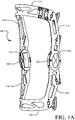
- FIGs. 1A and 1B show an exemplary orthopedic brace 10 incorporating upper and lower support cuffs 12a, 12b to engage the thigh and shin of a user.
- Upper support struts 14a and 14b extend downward from the upper support cuff 12a and lower support struts 16a and 16b extend upward from the lower support cuff 12b.
- the upper and lower support struts are engaged in hinge assemblies 18a and 18b. While shown for the embodiments herein as an orthopedic brace for the leg and knee, the embodiments disclosed herein would be equally applicable to braces for other extremities such as the arm and elbow.
- Extension angle limit elements have surface tabs 20a and 20b while flexion angle limit elements have surface tabs 22a and 22b.
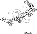
- the hinge assemblies and struts of one medial or lateral side of the brace are shown in detail in FIGs. 2A and 2B .
- the upper strut 14 and lower strut 16 are received in the hinge assembly 18.
- the hinge assembly 18 has a hinge plate 24 and a hinge assembly cap 26.
- An extension angle limit element having surface tab 20 is received in an anterior port 28 between the hinge plate 24 and hinge assembly cap 26 (seen in FIG. 2A ) in the hinge assembly 18.
- a flexion angle limit element having surface tab 22 is received in a posterior port 30 between the hinge plate 24 and hinge assembly cap 26 (seen in FIG. 2B in the hinge assembly 18.
- the upper strut 14 has an upper pivot hole 32 which is aligned with an upper axle bore 34 on the hinge plate 24 and the lower strut 16 has a lower pivot hole 36 which is aligned with a lower axle bore 38 on the hinge plate.
- Bolts 40 are received through the upper and lower axle bores and upper and lower pivot holes to act as rotational axles for the flexion and extension of the brace struts.
- Gear teeth 42 and 44 on the upper and lower struts respectively are engaged to coordinate rotation of the struts in the hinge assembly.
- Bushings 46 may be engaged in the pivot holes to facilitate smooth rotation and securing nuts 48 engage the bolts 40 through upper and lower exterior bores 50 and 52 in the hinge assembly cap 26.
- An outer cover 54 may be employed to mask the securing nuts in the hinge assembly cap and an inner cover 56 may be employed to mask the bolts 40 in the hinge plate 24.
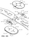
- Extension angle limit element 60 and flexion angle limit element 62 are seen in FIG. 2C .
- the extension angle limit element 60 has a body 64 which includes limiting surfaces 66 which are adapted to be engaged by mating faces 68 indented in anterior edges of the struts 14, 16.
- the surface tab 20 of the extension angle limit element 60 is received in an anterior recess 70 in the hinge plate 24 when the body of the extension angle limit element is received in the anterior port between the hinge plate and hinge assembly cap 26 (as described with respect to FIG. 2A ).
- Engagement of the surface tab 20 in the recess 70 limits the insertion depth of the extension angle limit element into the port.
- a raised stop 71 also engages the body to limit insertion depth.
- a bottom relief 72 also seen in FIG.
- extension angle limit element in the recess 70 allows a lower edge of the surface tab 20 to be grasped with a fingernail to assist in removal of the extension angle limit element from the port as will be described subsequently.
- the extension angle limit element is restrained in the port with a resilient lever 74 extending from the body 64 which is engaged in a mating channel 76 in the hinge assembly cap 26 (shown inverted in FIG. 2D to show the features on the lower surface).
- the flexion angle limit element 62 has a body 78 which includes limiting surfaces 80 which are adapted to be engaged by mating faces 82 indented in the posterior edges the struts 14, 16.
- the surface tab 22 of the flexion angle limit element 62 is received in a posterior recess 84 in the hinge plate 24 when the body of the flexion angle limit element is received in the posterior port between the hinge plate and hinge assembly cap 26 (as described with respect to FIG. 2A ).
- Engagement of the surface tab 22 in the recess 84 limits the insertion depth of the flexion angle limit element into the port.
- a raised stop 85 also engages the body to limit insertion depth.
- a bottom relief 86 (seen in FIG.
- flexion angle limit element in the recess 70 allows a lower edge of the surface tab 22 to be grasped with a fingernail for removal of the flexion angle limit element from the port.
- the flexion angle limit element is restrained in the port with a resilient lever 88 extending from the body 64 which is engaged in a mating channel 90 in the hinge assembly cap 26.
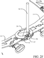
- a pen 92 or similar pointed tool is inserted through an aperture 94 extending through the hinge assembly cap 26 into the associated channel; using the flexion angle limit element as an example as shown in FIG. 2E , channel 90 for the flexion angle limit element.
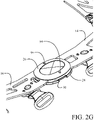
- the pen 92 depresses the lever 88 to clear the channel 90 as shown in FIG. 2F allowing the flexion angle limit element 62 to be removed from the port 30 as shown in FIG. 2G .
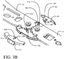
- FIGs. 3A and 3B A second embodiment is shown in FIGs. 3A and 3B with the hinge assembly cap removed wherein the extension and flexion angle limit elements 62 and 64 are constrained in the ports in the hinge assembly with cylindrical buttons 100 and 102 received in cylindrical cutouts 104 and 106 in the bodies 64 and 78 respectively.
- Channels 108 and 110 cut into the bodies 64 and 78 transecting the cylindrical cutouts 104 and 106.
- Buttons 100 and 102 are depressible into the hinge plate 26 by engaging extending tabs 112 and 114 with the pen 92 or similar tool extending through apertures 94 in the hinge assembly cap (as described with respect to FIG. 2E ).
- the transecting channels 108 and 110 are sized for clearance with the tabs 112 and 114 to allow insertion or extraction of the angle limit elements from the hinge assembly ports when the buttons are depressed.
- FIGs. 4A and 4B A third embodiment is shown in FIGs. 4A and 4B with the hinge assembly cap 26 rotated 90° to show features on the lower surface.
- the bodies 64 and 78 of the extension and flexion angle limit elements 60 and 62 are substantially bifurcated with capped slots 116 and 118 to form flexible jaw pairs 120a, 120b and 122a, 122b.
- the capped slots have transverse reliefs 124 and 126 and substantially cylindrical indentations 128 and 130.
- the cylindrical indentations of the jaws resiliently receive restraining posts 132 and 134 which depend from a lower surface of the hinge assembly cap 26 (or in alternative embodiments extend from an upper surface of the hinge plate 24) to extend between the hinge plate and hinge assembly cap.
- the jaw pairs are sufficiently flexible to allow insertion and extraction of the angle limit elements from the ports in the hinge assembly.
- key holes 136 and 138 may be present proximate the transverse reliefs to allow insertion of the pen 92 through apertures 94 to urge the jaw pairs apart to more easily extract the angle limit elements.
- FIG. 5A shows and example of angle limit elements sized to constrain the brace at 0° for both extension and flexion.
- limiting surfaces 66 are located at the vertical extents of body 64 and are adapted to be engaged by mating faces 68 indented in the anterior surfaces of the struts 14, 16.
- the surface tab 20 is received in the recess 70 in the hinge plate 24 when the body of the extension angle limit element is received in the anterior port between the hinge plate and hinge assembly cap 26. Sizing of the surface tab 20 to be received the anterior recess 70 assures that a proper extension angle limit element is installed in the anterior port.
- Shaping of the limiting surfaces 66 and the mating faces 68 is made to employ the mechanical leverage present in the rotation of the struts in extension to prevent the extension angle limit element from being squeezed out of the port as the struts reach the constrained extension angle.
- Points 140 in the mating faces 68 engage the limiting surfaces 66 to provide a clamping effect urging the extension angle element inward with extension pressure.
- limiting surfaces 80 are located at the vertical extents of body 78 and are adapted to be engaged by mating faces 82 indented in the posterior surfaces the struts 14, 16.
- the surface tab 22 of the extension angle limit element 62 is received in a recess 84 in the hinge plate 24 when the body of the extension angle limit element is received in the posterior port between the hinge plate and hinge assembly cap 26. Sizing of the surface tab 22 to be received the posterior recess 84 assures that a proper flexion angle limit element is installed in the posterior port.
- Shaping of the limiting surfaces 80 and the mating faces 82 is again made to employ the mechanical force present in the rotation of the struts in flexion to prevent the flexion angle limit element from being squeezed out of the port as the struts reach at the constrained flexion angle.
- Rounded protrusions 142 in the limiting surfaces 80 are received in cutouts 144 in the mating faces 82 provide a clamping effect squeezing the flexion angle element for additional restraining effect with flexion pressure.
- the width 150 of the body 64 in the extension angle limit element 60 between the limiting surfaces 66 determines the maximum extension angle for rotation of the struts 14, 16.
- the sizing of the extension angle limit element 60 allows rotation of the struts to 0° (full extension).
- the width 152 of the flexion angle limit element 62 between the limiting surfaces 80 determines the maximum flexion angle for rotation of the struts 14, 16.
- the sizing of the flexion angle limit element 62 restricts the struts to 0° of flexion (no flexion).
- the combination of angle limit elements in FIG. 5A locks the brace at 0°.
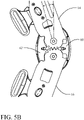
- FIG. 5B the flexion angle limit element 62 has been replaced with a flexion angle limit element 62' with reduced width to allow 20° of flexion and the brace is shown at the flexion limit.
- FIG. 5C shows the brace with flexion angle limit element 62' inserted in the posterior port and the struts positioned at a flexion angle of 15° demonstrating freedom of rotation of the struts between 0° and 20°.
- FIG. 5D shows the brace with extension angle limit element 60 replaced with an extension angle limit element 60' in the anterior port wherein the extension angle limit element 60' has an increased width to limit extension to 15°.
- the brace is shown at the limited extension angle with mating surfaces 68 in contact with the limiting surfaces 66. Flexion angle limit element 62' is not yet engaged by the mating surfaces 80 in the struts and is free to flex to the 20° flexion angle.
- Operation of the brace for fixing the desired extension and flexion angles is accomplished by selecting the appropriate extension angle limit element and flexion angle limit element with base widths providing contact of the limiting surfaces and mating surfaces at the limit angles.
- the flexion angle limit element With the brace struts at a rotation angle equal to or less than the desired maximum flexion angle, the flexion angle limit element is inserted in the posterior port in the hinge assembly.
- the engagement mechanism With the tab received in the posterior recess in the hinge plate to assure that a flexion angle limit element is being installed, the engagement mechanism secures the flexion angle limit element in the posterior port.
- the selected extension angle limit element is inserted in the anterior port in the hinge assembly.
- the engagement mechanism secures the extension angle limit element in the anterior port.
- the angle limit elements may be removed and replaced, without removal of the brace from the patient if desired, by adjusting the flexion/extension angle of the struts to relax pressure between the limiting surfaces on the angle limit elements and mating surfaces on the struts and disengaging the engagement mechanism for the angle limit elements as described for the embodiments disclosed. Either or both angle limit elements may then be removed from their ports. A different size angle limit element may then be installed using the insertion procedures previously described.
Landscapes
- Health & Medical Sciences (AREA)
- Vascular Medicine (AREA)
- Animal Behavior & Ethology (AREA)
- Engineering & Computer Science (AREA)
- Biomedical Technology (AREA)
- Heart & Thoracic Surgery (AREA)
- Nursing (AREA)
- Life Sciences & Earth Sciences (AREA)
- Orthopedic Medicine & Surgery (AREA)
- General Health & Medical Sciences (AREA)
- Public Health (AREA)
- Veterinary Medicine (AREA)
- Prostheses (AREA)
- Orthopedics, Nursing, And Contraception (AREA)
- Pivots And Pivotal Connections (AREA)
Description
- Embodiments of the disclosure relate generally to the field of anatomical support braces and more particularly to a system for limiting the range of flexion and extension in a brace hinge including a flexion angle limit element removably insertable on a first side of the hinge body and an extension angle limit element removably insertable on a second side of the hinge body, each of the extension angle limit element and flexion angle limit element each have two limiting faces which engage supporting struts.
- Orthopedic braces are used for various treatment and prophylactic purposes. For knee braces, particular uses may require incorporating an angle limiting function to resist knee flexion or extension past certain levels. Users may require multiple angles of limitation during the use of an orthopedic knee brace. Users prefer that the angle limiting system be adjustable for different angles.
- It is therefore desirable to provide a system for adjusting the flexion and extension limiting system rapidly and easily.
-
US 5 772 618 A discloses a hinge that is provided for an orthopedic brace that pivotally couples the ends of upper and lower arms of the brace. The hinge includes a pair of hinge plates, each having a rigid support member enclosed within an inner covering and an outer covering that integrally form a continuous unitary covering providing the hinge plate with a smooth, friction-reduced surface. The ends of the upper and lower arms are positioned between the hinge plates and the plates and ends are interconnected such that the ends of the upper and lower arms rotatably engage the friction-reduced surfaces of the hinge plates. -
US 2004/0049140 A1 discloses a lockable hinge for use in orthopedic braces. When used in a knee brace, the present hinge provides a knee-immobilizing brace that assists persons with standing and/or walking. The hinge is easily converted from a locked mode to a free range of motion mode and vice versa. When the hinge is in the locked mode, patients are better able to stand and walk. With the push of a button, the patient can bend his or her knee to sit or lie down more comfortably. When the hinge is in the free range of motion mode, patients are better able to participate in physical therapy activities without the hinge locking. -
US 2016/058596 A1 discloses a joint orthosis that includes upper and lower members, and a joint mechanism. The joint mechanism includes a shielding cover and at least one of modular front and rear inserts. Each of the modular front and rear inserts is disposed to limit movement of a joint of a human body in a flexion/extension direction. The shielding cover is removably attached to a mounting frame of the joint mechanism and is configured to conceal and prevent access to the at least one or the modular front and rear inserts. - Embodiments disclosed herein provide an angle limitation system for an orthopedic brace having a hinge assembly rotatably receiving an upper strut and a lower strut and having a hinge plate and a hinge assembly cap. An extension angle limit element is removably insertable in an anterior port between the hinge plate and hinge assembly cap. The extension angle limit element has a body with limiting surfaces adapted to engage mating faces indented in the anterior edges of the upper and lower strut. A flexion angle limit element is removably insertable in a posterior port between the hinge plate and hinge assembly cap. The flexion angle limit element has a body with limiting surfaces adapted to engage mating faces indented in the posterior edges of the upper and lower strut. Engagement mechanisms are adapted to releasably secure the flexion angle limit element in the posterior port and the engagement angle limit element in the anterior port.
- The features, functions, and advantages that have been discussed can be achieved independently in various embodiments of the present disclosure or may be combined in yet other embodiments further details of which can be seen with reference to the following description and drawings.
-
-
FIG. 1A is a front perspective view of an orthopedic brace configured to incorporate the embodiments disclosed herein; - [Para 8]
FIG. 1B is a rear perspective view of the brace ofFIG. 1A ; - [Para 9]
FIG. 2A is a front perspective view of one of the support struts and hinge assembly of the brace; - [Para 10]
FIG. 2B is a rear perspective view of one of the support struts and hinge assembly of the brace; - [Para 11]
FIG. 2C is an exploded front perspective view of one of the support struts and hinge assembly of the brace with a first embodiment of the angle limit elements and the associated securing system; - [Para 12]
FIG. 2D is a detailed exploded front perspective view of one of the support struts and hinge assembly of the brace with the first embodiment of the angle limit elements and the associated securing system with the hinge assembly cap inverted to show the engagement reliefs; - [Para 13]
FIG. 2E is a detailed rear perspective view of the hinge assembly and struts with a pen inserted in the disengagement orifice to depress the locking strut on the flexion angle limit element; - [Para 14]
FIG. 2F is a detailed rear perspective view of the hinge assembly and struts with a partial cutaway of the hinge assembly cap to show engagement of the pen to depress the locking strut on the flexion angle limit element; - [Para 1 5]
FIG. 2G is a detailed rear perspective view of the hinge assembly and struts as seen inFIGs. 2E and2F with the flexion angle limit element removed from the posterior port in the hinge assembly; - [Para 16]
FIG. 3A is a detailed rear perspective view of a second embodiment of the angle limit elements and the associated securing system with the hinge assembly cap removed for clarity; - [Para 1 7]
FIG. 3B is a detailed rear perspective view of the second embodiment of the angle limit elements and the associated securing system with the hinge assembly cap removed and the angle limit elements removed to show the catch buttons; - [Para 18]
FIG. 4A is a detailed rear perspective view of a third embodiment of the angle limit elements and the associated securing system with the hinge assembly cap exploded and rotated 90° to show the catch posts; - [Para 19]
FIG. 4B is a detailed rear perspective view of the third embodiment of the angle limit elements and the associated securing system with the hinge assembly cap exploded and rotated 90° and the extension angle limit element engaged to the associated catch post and the flexion angle limit element disengaged from the catch post; - [Para 20]
FIG. 5A is a detailed side view of the second embodiment with the hinge assembly cap removed showing flexion and extension angle limit elements sized to lock the brace struts at a zero flexion and zero extension angle; - [Para 21]
FIG. 5B is a detailed side view of the second embodiment with the hinge assembly cap removed showing the flexion angle limit element sized to allow 20° of flexion in the brace struts and the extension angle limit element sized for zero extension angle; - [Para 22]
FIG. 5C is a detailed side view of the second embodiment with the hinge assembly cap removed and the 20° flexion angle limit element and 0° extension angle limit element ofFIG. 5B but with the brace flexed at 15° to demonstrate the freedom of movement between the limiting angles; and, - [Para 23]
FIG. 5D is a detailed side view of the second embodiment with the hinge assembly cap removed showing the flexion angle limit element sized to allow 20° of flexion in the brace struts and the extension angle limit element sized for limiting extension angle at 15°. - Embodiments disclosed herein provide an angle limitation system for an orthopedic brace having a flexion angle limit element removably insertable on a posterior side of the hinge body and an extension angle limit element removably insertable on an anterior side of the hinge body. The extension angle limit element and flexion angle limit element are received in ports in the hinge body formed between a hinge plate and hinge assembly cap. Each angle limit element has two limiting surfaces which engage mating faces on the supporting struts of the brace to limit extension angle and flexion angle respectively. Engagement mechanisms adapted to secure the angle limit elements in the ports are provided. In a first embodiment for the engagement mechanism, the angle limit elements are held in place with a flexible strut or tab on the angle limit element received in a mating channel in a bottom surface of the hinge assembly cap. The angle limit elements are removable by depressing the strut with a tool inserted through apertures in the hinge assembly cap into the channel. A second embodiment of the engagement mechanism provides for jaws on the angle limit element with a releasable button received in a cylindrical cutout in the jaws to restrain the angle limit element in the port. In a third embodiment the angle limit elements are restrained in the port by flexible jaws engaging a catch post. The angle limit elements are insertable and removable without disassembly of the hinge elements or removal of the brace from the patient. Selectable angle limit elements with limiting surfaces having differing total angle may be removably inserted into the ports to vary either the extension angle or the flexion angle.
- Referring to the drawings,
FIGs. 1A and1B show an exemplaryorthopedic brace 10 incorporating upper andlower support cuffs upper support cuff 12a and lower support struts 16a and 16b extend upward from thelower support cuff 12b. The upper and lower support struts are engaged inhinge assemblies - For disclosure of position, surface tabs for flexion and extension angle limit elements engaged in the hinge assemblies, as will be described in greater detail subsequently, are shown in
FIGs. 1A and1B . Extension angle limit elements havesurface tabs surface tabs - The hinge assemblies and struts of one medial or lateral side of the brace are shown in detail in
FIGs. 2A and2B . Theupper strut 14 andlower strut 16 are received in thehinge assembly 18. Thehinge assembly 18 has ahinge plate 24 and ahinge assembly cap 26. An extension angle limit element havingsurface tab 20 is received in ananterior port 28 between thehinge plate 24 and hinge assembly cap 26 (seen inFIG. 2A ) in thehinge assembly 18. A flexion angle limit element havingsurface tab 22 is received in aposterior port 30 between thehinge plate 24 and hinge assembly cap 26 (seen inFIG. 2B in thehinge assembly 18. - Seen in the exploded view of
FIG. 2C for an exemplary embodiment, theupper strut 14 has anupper pivot hole 32 which is aligned with an upper axle bore 34 on thehinge plate 24 and thelower strut 16 has alower pivot hole 36 which is aligned with a lower axle bore 38 on the hinge plate.Bolts 40 are received through the upper and lower axle bores and upper and lower pivot holes to act as rotational axles for the flexion and extension of the brace struts.Gear teeth Bushings 46 may be engaged in the pivot holes to facilitate smooth rotation and securingnuts 48 engage thebolts 40 through upper and lower exterior bores 50 and 52 in thehinge assembly cap 26. Anouter cover 54 may be employed to mask the securing nuts in the hinge assembly cap and aninner cover 56 may be employed to mask thebolts 40 in thehinge plate 24. Extensionangle limit element 60 and flexionangle limit element 62 are seen inFIG. 2C . - Details of a first embodiment for the angle limit elements and the associated engagement mechanisms for retention in the ports are shown in
FIG. 2D . The extensionangle limit element 60 has abody 64 which includes limitingsurfaces 66 which are adapted to be engaged by mating faces 68 indented in anterior edges of thestruts surface tab 20 of the extensionangle limit element 60 is received in ananterior recess 70 in thehinge plate 24 when the body of the extension angle limit element is received in the anterior port between the hinge plate and hinge assembly cap 26 (as described with respect toFIG. 2A ). Engagement of thesurface tab 20 in therecess 70 limits the insertion depth of the extension angle limit element into the port. A raisedstop 71 also engages the body to limit insertion depth. A bottom relief 72 (also seen inFIG. 1B ) in therecess 70 allows a lower edge of thesurface tab 20 to be grasped with a fingernail to assist in removal of the extension angle limit element from the port as will be described subsequently. The extension angle limit element is restrained in the port with aresilient lever 74 extending from thebody 64 which is engaged in amating channel 76 in the hinge assembly cap 26 (shown inverted inFIG. 2D to show the features on the lower surface). - Similarly, the flexion
angle limit element 62 has abody 78 which includes limitingsurfaces 80 which are adapted to be engaged by mating faces 82 indented in the posterior edges thestruts surface tab 22 of the flexionangle limit element 62 is received in aposterior recess 84 in thehinge plate 24 when the body of the flexion angle limit element is received in the posterior port between the hinge plate and hinge assembly cap 26 (as described with respect toFIG. 2A ). Engagement of thesurface tab 22 in therecess 84 limits the insertion depth of the flexion angle limit element into the port. A raised stop 85 also engages the body to limit insertion depth. A bottom relief 86 (seen inFIG. 1B ) in therecess 70 allows a lower edge of thesurface tab 22 to be grasped with a fingernail for removal of the flexion angle limit element from the port. The flexion angle limit element is restrained in the port with aresilient lever 88 extending from thebody 64 which is engaged in amating channel 90 in thehinge assembly cap 26. - When the extension
angle limit element 60 and flexionangle limit element 62 are received in their respective ports thelevers mating channels pen 92 or similar pointed tool, is inserted through anaperture 94 extending through thehinge assembly cap 26 into the associated channel; using the flexion angle limit element as an example as shown inFIG. 2E ,channel 90 for the flexion angle limit element. Thepen 92 depresses thelever 88 to clear thechannel 90 as shown inFIG. 2F allowing the flexionangle limit element 62 to be removed from theport 30 as shown inFIG. 2G . - A second embodiment is shown in
FIGs. 3A and3B with the hinge assembly cap removed wherein the extension and flexionangle limit elements cylindrical buttons cylindrical cutouts bodies Channels bodies cylindrical cutouts Buttons hinge plate 26 by engaging extendingtabs pen 92 or similar tool extending throughapertures 94 in the hinge assembly cap (as described with respect toFIG. 2E ). The transectingchannels tabs - A third embodiment is shown in
FIGs. 4A and4B with thehinge assembly cap 26 rotated 90° to show features on the lower surface. Thebodies angle limit elements slots flexible jaw pairs transverse reliefs cylindrical indentations posts key holes pen 92 throughapertures 94 to urge the jaw pairs apart to more easily extract the angle limit elements. - For any of the restraining embodiments described, operation of the extension and flexion angle limit elements in the brace is substantially identical.
FIG. 5A shows and example of angle limit elements sized to constrain the brace at 0° for both extension and flexion. For the extensionangle limit element 60, limitingsurfaces 66 are located at the vertical extents ofbody 64 and are adapted to be engaged by mating faces 68 indented in the anterior surfaces of thestruts surface tab 20 is received in therecess 70 in thehinge plate 24 when the body of the extension angle limit element is received in the anterior port between the hinge plate and hingeassembly cap 26. Sizing of thesurface tab 20 to be received theanterior recess 70 assures that a proper extension angle limit element is installed in the anterior port. Shaping of the limitingsurfaces 66 and the mating faces 68 is made to employ the mechanical leverage present in the rotation of the struts in extension to prevent the extension angle limit element from being squeezed out of the port as the struts reach the constrained extension angle.Points 140 in the mating faces 68 engage the limitingsurfaces 66 to provide a clamping effect urging the extension angle element inward with extension pressure. - Similarly, for the flexion
angle limit element 62 limitingsurfaces 80 are located at the vertical extents ofbody 78 and are adapted to be engaged by mating faces 82 indented in the posterior surfaces thestruts surface tab 22 of the extensionangle limit element 62 is received in arecess 84 in thehinge plate 24 when the body of the extension angle limit element is received in the posterior port between the hinge plate and hingeassembly cap 26. Sizing of thesurface tab 22 to be received theposterior recess 84 assures that a proper flexion angle limit element is installed in the posterior port. Shaping of the limitingsurfaces 80 and the mating faces 82 is again made to employ the mechanical force present in the rotation of the struts in flexion to prevent the flexion angle limit element from being squeezed out of the port as the struts reach at the constrained flexion angle.Rounded protrusions 142 in the limitingsurfaces 80 are received incutouts 144 in the mating faces 82 provide a clamping effect squeezing the flexion angle element for additional restraining effect with flexion pressure. - The
width 150 of thebody 64 in the extensionangle limit element 60 between the limitingsurfaces 66 determines the maximum extension angle for rotation of thestruts FIG. 5A the sizing of the extensionangle limit element 60 allows rotation of the struts to 0° (full extension). Similarly, thewidth 152 of the flexionangle limit element 62 between the limitingsurfaces 80 determines the maximum flexion angle for rotation of thestruts FIG. 5A the sizing of the flexionangle limit element 62 restricts the struts to 0° of flexion (no flexion). The combination of angle limit elements inFIG. 5A locks the brace at 0°. - In
FIG. 5B , the flexionangle limit element 62 has been replaced with a flexion angle limit element 62' with reduced width to allow 20° of flexion and the brace is shown at the flexion limit.FIG. 5C shows the brace with flexion angle limit element 62' inserted in the posterior port and the struts positioned at a flexion angle of 15° demonstrating freedom of rotation of the struts between 0° and 20°.FIG. 5D shows the brace with extensionangle limit element 60 replaced with an extension angle limit element 60' in the anterior port wherein the extension angle limit element 60' has an increased width to limit extension to 15°. InFIG. 5D the brace is shown at the limited extension angle withmating surfaces 68 in contact with the limiting surfaces 66. Flexion angle limit element 62' is not yet engaged by the mating surfaces 80 in the struts and is free to flex to the 20° flexion angle. - Operation of the brace for fixing the desired extension and flexion angles is accomplished by selecting the appropriate extension angle limit element and flexion angle limit element with base widths providing contact of the limiting surfaces and mating surfaces at the limit angles. With the brace struts at a rotation angle equal to or less than the desired maximum flexion angle, the flexion angle limit element is inserted in the posterior port in the hinge assembly. With the tab received in the posterior recess in the hinge plate to assure that a flexion angle limit element is being installed, the engagement mechanism secures the flexion angle limit element in the posterior port. With the brace struts flexed at or beyond the maximum extension limit angle, the selected extension angle limit element is inserted in the anterior port in the hinge assembly. With the tab received in the anterior recess in the hinge plate to assure that an extension angle limit element is being installed, the engagement mechanism secures the extension angle limit element in the anterior port. The angle limit elements may be removed and replaced, without removal of the brace from the patient if desired, by adjusting the flexion/extension angle of the struts to relax pressure between the limiting surfaces on the angle limit elements and mating surfaces on the struts and disengaging the engagement mechanism for the angle limit elements as described for the embodiments disclosed. Either or both angle limit elements may then be removed from their ports. A different size angle limit element may then be installed using the insertion procedures previously described.
- Having now described various embodiments of the disclosure in detail as required by the patent statutes, those skilled in the art will recognize modifications and substitutions to the specific embodiments disclosed herein. Such modifications are within the scope and intent of the present disclosure as defined in the following claims.
Claims (9)
- An angle limitation system for an orthopedic brace comprising:a hinge assembly (18a, 18b) rotatably receiving an upper strut (14a, 14b) and a lower strut (16a, 16b) and having a hinge plate (24) and a hinge assembly cap (26);an extension angle limit element (60) removably insertable in an anterior port (28) between the hinge plate and hinge assembly cap, said extension angle limit element having a body (64) with limiting surfaces (66) adapted to engage mating faces (68) indented in anterior edges of the upper and lower strut;a flexion angle limit element (62) removably insertable in a posterior port (30) between the hinge plate and hinge assembly cap, said flexion angle limit element having a body (78) with limiting surfaces (80) adapted to engage mating faces (82) indented in posterior edges of the upper and lower strut; and,engagement mechanisms adapted to releasably secure the flexion angle limit element in the posterior port and the engagement angle limit element in the anterior port; characterised in that the engagement mechanisms comprise a resilient lever (74,88) extendingfrom each body, said resilient lever engaged in a mating channel (76, 90) in the hinge assembly cap to prevent extraction of the body from the respective anterior or posterior port, the hinge assembly cap having apertures (94) eachextending through the hinge assembly cap into the associated mating channel said apertures being configured to receive tool (92) inserted to engage the resilient lever wherebydepression of the lever by the tool disengages the lever from the mating channel.
- The angle limitation system for an orthopedic brace as defined in claim 1 wherein the limiting surfaces and the mating faces are shaped to employ mechanical leverage present in rotation of the struts to prevent the extension or flexion angle limit elements from being squeezed out of the anterior or posterior port as the struts reach a constrained extension angle.
- The angle limitation system for an orthopedic brace as defined in claim 2 further comprising points (140) in the mating faces engaging the limiting surfaces to provide a clamping effect.
- The angle limitation system for an orthopedic brace as defined in claim 2 further comprising rounded protrusions (142) in the limiting surfaces received in cutouts (144) in the mating faces to provide a clamping effect.
- The angle limitation system for an orthopedic brace as defined in claim 1 further comprising:a first surface tab (20) extending from the extension angle limit element and received in an anterior recess (70) in the hinge plate when the body of the extension angle limit element is received in the anterior port; anda second surface tab (22) extending from the flexion angle limit element and received in a posterior recess (84) in the hinge plate when the body of the flexion angle limit element is received in the posterior port between the hinge plate and hinge assembly cap;said first and second surface tabs adapted to be received only in the anterior recess and posterior recess respectively.
- The angle limitation system for an orthopedic brace as defined in claim 5 further comprising a relief (72) in each of the anterior recess and posterior recess allowing engagement of the first and second surface tabs for removal of the extension angle limit element and flexion angle limit element.
- A method for operation of an orthopedic brace comprising:selecting an appropriate extension angle limit element (60) and flexion angle limit element (62) with base widths providing contact of limiting surfaces (66, 80) and mating surfaces (68, 82) at desired limit angles;rotating an upper strut (14a, 14b) and a lower strut (16a, 16b) of a hinge assembly, rotatably receiving the upper strut and the lower strut and having a hinge plate (24) and a hinge assembly cap (26), to an angle equal to or less than the desired maximum flexion angle;inserting the selected flexion angle limit element removably insertable in a posterior port (30) between the hinge plate and hinge assembly cap, said flexion angle limit element having a body (78) with limiting surfaces (80) adapted to engage mating faces (82) indented in posterior edges of the upper and lower strut in the posterior port in the hinge assembly; and,releasably securing the flexion angle limit element in the posterior port with an engagement mechanism comprising a first resilient lever (88) extending from the body, said resilient lever engaged in a first mating channel (90) in the hinge assembly cap to prevent extraction of the body from the posterior port, the hinge assembly cap having a first aperture (90) extending through the hinge assembly cap into the first mating channel said first aperture receiving a tool (92) inserted to engage the resilient lever whereby depression of the first resilient lever by the tool disengages the first resilient lever from the first mating channel;flexing brace struts at or beyond a maximum extension limit angle;inserting the selected extension angle limit element (60) removably insertable in an anterior port (28) between the hinge plate and hinge assembly cap (26), said extension angle limit element having a body is (64) with limiting surfaces (66) adapted to engage mating faces (68) indented in anterior edges of the upper and lower strut in the anterior port in the hinge assembly of the brace;releasably securing the extension angle limit element in the anterior port with an engagement mechanism comprising a second resilient lever (74) extending from the body, said resilient lever engaged in a second mating channel (90) in the hinge assembly cap to prevent extraction of the body from the anterior port, the hinge assembly cap having a second apertun (90) extending through the hinge assembly cap into the second mating channel said second aperture receiving a tool (92) inserted to engage the resilient lever whereby depression of the first resilient lever by the tool disengages the second resilient lever from the second mating channel.
- A method for operation of an orthopedic brace as defined in claim 7 further comprising:adjusting the flexion/extension angle of the struts to relax pressure between the limiting surfaces on the extension and flexion angle limit elements and mating surfaces on the struts;disengaging the engagement mechanism for the extension and flexion angle limit elements; and,removing either or both the extension and flexion angle limit elements from the anterior and posterior ports.
- A method for operation of an orthopedic brace as defined in claim 7 further comprising:receiving a first surface tab (20) in an anterior recess (70) in the hinge plate to assure that the extension angle limit element is being installed, andreceiving a second surface tab (22) in a posterior recess (84) in the hinge plate to assure that the flexion angle limit element is being installed.
Applications Claiming Priority (2)
| Application Number | Priority Date | Filing Date | Title |
|---|---|---|---|
| US201662343568P | 2016-05-31 | 2016-05-31 | |
| PCT/US2017/035040 WO2017210212A1 (en) | 2016-05-31 | 2017-05-30 | Flexion and extension range limiting hinge for an orthopedic brace |
Publications (3)
| Publication Number | Publication Date |
|---|---|
| EP3463207A1 EP3463207A1 (en) | 2019-04-10 |
| EP3463207A4 EP3463207A4 (en) | 2020-03-04 |
| EP3463207B1 true EP3463207B1 (en) | 2022-04-20 |
Family
ID=60420709
Family Applications (1)
| Application Number | Title | Priority Date | Filing Date |
|---|---|---|---|
| EP17807343.3A Active EP3463207B1 (en) | 2016-05-31 | 2017-05-30 | Flexion and extension range limiting hinge for an orthopedic brace |
Country Status (5)
| Country | Link |
|---|---|
| US (1) | US10758392B2 (en) |
| EP (1) | EP3463207B1 (en) |
| JP (1) | JP2019520131A (en) |
| AU (1) | AU2017273450B2 (en) |
| WO (1) | WO2017210212A1 (en) |
Families Citing this family (7)
| Publication number | Priority date | Publication date | Assignee | Title |
|---|---|---|---|---|
| DE102015217205A1 (en) * | 2015-09-09 | 2017-03-09 | Bauerfeind Ag | Schwenklimitierbares biaxial joint |
| CN109998754B (en) * | 2018-05-02 | 2024-08-30 | 玛瑜科创服务(南京)有限公司 | Knee joint orthosis |
| WO2020123583A1 (en) * | 2018-12-11 | 2020-06-18 | Ossur Iceland Ehf | Hinge having a rotation-stop lock |
| US11607330B1 (en) * | 2019-01-21 | 2023-03-21 | Medical Specialties, Inc. | Orthopedic and orthotic brace and hinge assembly with custom-selectable range-controlling hinge stops |
| IT201900014856A1 (en) * | 2019-08-20 | 2021-02-20 | Tenortho S R L Unipersonale | JOINT FOR ARTICULATION |
| CN214063552U (en) | 2020-12-15 | 2021-08-27 | 合肥维信诺科技有限公司 | A bending unit, hinge and flexible module bending device |
| EP4547170A1 (en) * | 2022-06-29 | 2025-05-07 | Ossur Iceland Ehf | Polymeric polycentric hinge |
Family Cites Families (22)
| Publication number | Priority date | Publication date | Assignee | Title |
|---|---|---|---|---|
| US4493316A (en) | 1983-03-10 | 1985-01-15 | Donjoy, Inc. | Articulating knee stabilizer |
| US4697583A (en) | 1985-01-29 | 1987-10-06 | Don Joy Orthopedic, Inc. | Four-point anterior cruciate ligament brace |
| US4732143A (en) | 1987-02-13 | 1988-03-22 | Spectrum Orthopedics, Ltd. | Selectable extension stop for a polycentric hinge |
| US4966133A (en) | 1988-09-08 | 1990-10-30 | Kausek James H | Knee brace for control of ligament stability |
| US5437619A (en) * | 1993-06-30 | 1995-08-01 | Empi, Inc. | Range-of-motion splint with eccentric spring |
| US5661596A (en) | 1994-02-03 | 1997-08-26 | Canon Kabushiki Kaisha | Antireflection film and exposure apparatus using the same |
| US5772618A (en) | 1996-05-31 | 1998-06-30 | Breg, Inc. | Hinge for an orthopedic brace |
| ATE366097T1 (en) | 1999-12-21 | 2007-07-15 | Dj Orthopedics Llc | JOINT FOR ORTHOPEDIC KNEE Brace AND KNEE Brace INTEGRATING THE JOINT |
| US6890314B2 (en) | 2001-08-31 | 2005-05-10 | Dj Orthopedics, Llc | Knee brace hinge deflector |
| US7488300B2 (en) * | 2002-02-15 | 2009-02-10 | Thusane | Bicentric hinge for use in a brace |
| JP3634807B2 (en) | 2002-02-20 | 2005-03-30 | キヤノン株式会社 | Process cartridge and image forming apparatus |
| US7235058B2 (en) * | 2002-09-11 | 2007-06-26 | Djo, Llc | Lockable hinge |
| US6764244B2 (en) | 2002-10-07 | 2004-07-20 | Timothy Thomas Pansiera | Pin stop for mechanical joints |
| ITVR20030027A1 (en) * | 2003-03-06 | 2004-09-07 | Fgp Srl | JOINT FOR ADJUSTABLE ANGULAR EXCURSION KNEE. |
| KR100688327B1 (en) * | 2006-01-09 | 2007-03-02 | 조상덕 | Orthopedic Knee Supports |
| DE102006021789A1 (en) | 2006-05-09 | 2007-11-22 | Otto Bock Healthcare Ip Gmbh & Co. Kg | joint orthosis |
| US7544174B2 (en) * | 2006-09-29 | 2009-06-09 | Djo, Llc | Quiet flexion/extension stop for orthopedic brace and orthopedic brace incorporating a quiet flexion/extension stop |
| DE102007009605A1 (en) | 2007-02-26 | 2008-08-28 | Otto Bock Healthcare Ip Gmbh & Co. Kg | Orthotic appliance bracing knee joint, includes jointed proximal and distal limbs, with side sections pivoting about axes at right angles to load-bearing joint axis |
| ITVR20110121A1 (en) * | 2011-05-27 | 2012-11-28 | Fgp Srl | JOINT FOR ORTHOPEDIC TUTOR WITH TWO UPRIGHTS FOR ADJUSTABLE ANGULAR EXCURSION |
| DE202011102331U1 (en) * | 2011-06-20 | 2011-08-22 | Conwell Medical Co., Ltd. | Rotary axis limiting device for a knee joint support |
| US9788986B2 (en) | 2014-02-11 | 2017-10-17 | Ossur Hf | Hinge for an orthopedic device |
| TWI556805B (en) | 2014-08-27 | 2016-11-11 | Plus Meditech Co Ltd | Hinge mechanism of hinged aligner |
-
2017
- 2017-05-30 EP EP17807343.3A patent/EP3463207B1/en active Active
- 2017-05-30 US US15/608,599 patent/US10758392B2/en active Active
- 2017-05-30 JP JP2018563540A patent/JP2019520131A/en active Pending
- 2017-05-30 AU AU2017273450A patent/AU2017273450B2/en active Active
- 2017-05-30 WO PCT/US2017/035040 patent/WO2017210212A1/en not_active Ceased
Also Published As
| Publication number | Publication date |
|---|---|
| AU2017273450B2 (en) | 2021-12-09 |
| WO2017210212A1 (en) | 2017-12-07 |
| EP3463207A1 (en) | 2019-04-10 |
| JP2019520131A (en) | 2019-07-18 |
| AU2017273450A1 (en) | 2019-01-17 |
| US10758392B2 (en) | 2020-09-01 |
| US20170340471A1 (en) | 2017-11-30 |
| EP3463207A4 (en) | 2020-03-04 |
Similar Documents
| Publication | Publication Date | Title |
|---|---|---|
| AU2017273450B2 (en) | Flexion and extension range limiting hinge for an orthopedic brace | |
| US7235058B2 (en) | Lockable hinge | |
| EP2345393B1 (en) | Motion controlling hinge for orthopaedic brace | |
| EP1996133B1 (en) | Adjustable ergonomic brace | |
| AU735286B2 (en) | Joint brace hinges | |
| EP3705104B1 (en) | Ankle brace or ankle exoskeleton | |
| CN115103659B (en) | Interface for exoskeleton | |
| AU2018423073B2 (en) | Posterior upright of ankle foot orthosis and ankle foot orthosis | |
| JP6530269B2 (en) | Elbow clutch | |
| US20210197018A1 (en) | Wheeled exercise apparatus | |
| US8920349B2 (en) | Joint for an orthopedic brace with two adjustable angular range uprights | |
| CN110812133B (en) | Walking stick with joint structure | |
| EP3482726A1 (en) | Hyper-extending orthopedic bust | |
| CN210433909U (en) | Supplementary exerciser of knee joint replacement postoperative | |
| KR102209135B1 (en) | Portable squat guide apparatus having laser pointer | |
| CN110279534A (en) | A kind of Novel leg-protective mechanism for Wheelchair for patient standing | |
| KR102956741B1 (en) | Wearable ring structure | |
| KR20070059539A (en) | Assistive devices for the treatment of knee arthritis diseases and pain relief | |
| US20230285216A1 (en) | Rehabilitative wrist training device for use by stroke patients | |
| KR101994936B1 (en) | Coin insertion apparatus for fine motor skill | |
| CN201438980U (en) | Rotating shaft device of protective equipment | |
| CN101027019A (en) | Knee joint prosthesis | |
| WO2022221731A1 (en) | Involuntary movement dampening device | |
| IT202100001877U1 (en) | ORTHOPEDIC ORTHOSIS FOR PRONO-SUPINATION EXERCISES WITH ADJUSTABLE ANGLE TRAVEL | |
| IT201900017342A1 (en) | ORTHOSIS APPLICABLE ON UPPER OR LOWER LIMBS FITTED WITH ACCESSORY USED FOR PRONO-SUPINATION EXERCISES WITH ADJUSTABLE ANGLE |
Legal Events
| Date | Code | Title | Description |
|---|---|---|---|
| STAA | Information on the status of an ep patent application or granted ep patent |
Free format text: STATUS: THE INTERNATIONAL PUBLICATION HAS BEEN MADE |
|
| PUAI | Public reference made under article 153(3) epc to a published international application that has entered the european phase |
Free format text: ORIGINAL CODE: 0009012 |
|
| STAA | Information on the status of an ep patent application or granted ep patent |
Free format text: STATUS: REQUEST FOR EXAMINATION WAS MADE |
|
| 17P | Request for examination filed |
Effective date: 20181227 |
|
| AK | Designated contracting states |
Kind code of ref document: A1 Designated state(s): AL AT BE BG CH CY CZ DE DK EE ES FI FR GB GR HR HU IE IS IT LI LT LU LV MC MK MT NL NO PL PT RO RS SE SI SK SM TR |
|
| AX | Request for extension of the european patent |
Extension state: BA ME |
|
| DAV | Request for validation of the european patent (deleted) | ||
| DAX | Request for extension of the european patent (deleted) | ||
| A4 | Supplementary search report drawn up and despatched |
Effective date: 20200203 |
|
| RIC1 | Information provided on ipc code assigned before grant |
Ipc: A61F 5/04 20060101ALI20200128BHEP Ipc: A61F 5/01 20060101ALI20200128BHEP Ipc: A61F 5/00 20060101AFI20200128BHEP |
|
| GRAP | Despatch of communication of intention to grant a patent |
Free format text: ORIGINAL CODE: EPIDOSNIGR1 |
|
| STAA | Information on the status of an ep patent application or granted ep patent |
Free format text: STATUS: GRANT OF PATENT IS INTENDED |
|
| INTG | Intention to grant announced |
Effective date: 20211115 |
|
| GRAS | Grant fee paid |
Free format text: ORIGINAL CODE: EPIDOSNIGR3 |
|
| GRAA | (expected) grant |
Free format text: ORIGINAL CODE: 0009210 |
|
| STAA | Information on the status of an ep patent application or granted ep patent |
Free format text: STATUS: THE PATENT HAS BEEN GRANTED |
|
| AK | Designated contracting states |
Kind code of ref document: B1 Designated state(s): AL AT BE BG CH CY CZ DE DK EE ES FI FR GB GR HR HU IE IS IT LI LT LU LV MC MK MT NL NO PL PT RO RS SE SI SK SM TR |
|
| REG | Reference to a national code |
Ref country code: GB Ref legal event code: FG4D |
|
| REG | Reference to a national code |
Ref country code: CH Ref legal event code: EP |
|
| REG | Reference to a national code |
Ref country code: IE Ref legal event code: FG4D |
|
| REG | Reference to a national code |
Ref country code: DE Ref legal event code: R096 Ref document number: 602017056310 Country of ref document: DE |
|
| REG | Reference to a national code |
Ref country code: AT Ref legal event code: REF Ref document number: 1484602 Country of ref document: AT Kind code of ref document: T Effective date: 20220515 |
|
| REG | Reference to a national code |
Ref country code: LT Ref legal event code: MG9D |
|
| REG | Reference to a national code |
Ref country code: NL Ref legal event code: MP Effective date: 20220420 |
|
| PG25 | Lapsed in a contracting state [announced via postgrant information from national office to epo] |
Ref country code: NL Free format text: LAPSE BECAUSE OF FAILURE TO SUBMIT A TRANSLATION OF THE DESCRIPTION OR TO PAY THE FEE WITHIN THE PRESCRIBED TIME-LIMIT Effective date: 20220420 |
|
| PG25 | Lapsed in a contracting state [announced via postgrant information from national office to epo] |
Ref country code: SE Free format text: LAPSE BECAUSE OF FAILURE TO SUBMIT A TRANSLATION OF THE DESCRIPTION OR TO PAY THE FEE WITHIN THE PRESCRIBED TIME-LIMIT Effective date: 20220420 Ref country code: PT Free format text: LAPSE BECAUSE OF FAILURE TO SUBMIT A TRANSLATION OF THE DESCRIPTION OR TO PAY THE FEE WITHIN THE PRESCRIBED TIME-LIMIT Effective date: 20220822 Ref country code: NO Free format text: LAPSE BECAUSE OF FAILURE TO SUBMIT A TRANSLATION OF THE DESCRIPTION OR TO PAY THE FEE WITHIN THE PRESCRIBED TIME-LIMIT Effective date: 20220720 Ref country code: LT Free format text: LAPSE BECAUSE OF FAILURE TO SUBMIT A TRANSLATION OF THE DESCRIPTION OR TO PAY THE FEE WITHIN THE PRESCRIBED TIME-LIMIT Effective date: 20220420 Ref country code: HR Free format text: LAPSE BECAUSE OF FAILURE TO SUBMIT A TRANSLATION OF THE DESCRIPTION OR TO PAY THE FEE WITHIN THE PRESCRIBED TIME-LIMIT Effective date: 20220420 Ref country code: GR Free format text: LAPSE BECAUSE OF FAILURE TO SUBMIT A TRANSLATION OF THE DESCRIPTION OR TO PAY THE FEE WITHIN THE PRESCRIBED TIME-LIMIT Effective date: 20220721 Ref country code: FI Free format text: LAPSE BECAUSE OF FAILURE TO SUBMIT A TRANSLATION OF THE DESCRIPTION OR TO PAY THE FEE WITHIN THE PRESCRIBED TIME-LIMIT Effective date: 20220420 Ref country code: ES Free format text: LAPSE BECAUSE OF FAILURE TO SUBMIT A TRANSLATION OF THE DESCRIPTION OR TO PAY THE FEE WITHIN THE PRESCRIBED TIME-LIMIT Effective date: 20220420 Ref country code: BG Free format text: LAPSE BECAUSE OF FAILURE TO SUBMIT A TRANSLATION OF THE DESCRIPTION OR TO PAY THE FEE WITHIN THE PRESCRIBED TIME-LIMIT Effective date: 20220720 |
|
| PG25 | Lapsed in a contracting state [announced via postgrant information from national office to epo] |
Ref country code: RS Free format text: LAPSE BECAUSE OF FAILURE TO SUBMIT A TRANSLATION OF THE DESCRIPTION OR TO PAY THE FEE WITHIN THE PRESCRIBED TIME-LIMIT Effective date: 20220420 Ref country code: PL Free format text: LAPSE BECAUSE OF FAILURE TO SUBMIT A TRANSLATION OF THE DESCRIPTION OR TO PAY THE FEE WITHIN THE PRESCRIBED TIME-LIMIT Effective date: 20220420 Ref country code: LV Free format text: LAPSE BECAUSE OF FAILURE TO SUBMIT A TRANSLATION OF THE DESCRIPTION OR TO PAY THE FEE WITHIN THE PRESCRIBED TIME-LIMIT Effective date: 20220420 Ref country code: IS Free format text: LAPSE BECAUSE OF FAILURE TO SUBMIT A TRANSLATION OF THE DESCRIPTION OR TO PAY THE FEE WITHIN THE PRESCRIBED TIME-LIMIT Effective date: 20220820 |
|
| REG | Reference to a national code |
Ref country code: DE Ref legal event code: R097 Ref document number: 602017056310 Country of ref document: DE |
|
| REG | Reference to a national code |
Ref country code: BE Ref legal event code: MM Effective date: 20220531 |
|
| PG25 | Lapsed in a contracting state [announced via postgrant information from national office to epo] |
Ref country code: SM Free format text: LAPSE BECAUSE OF FAILURE TO SUBMIT A TRANSLATION OF THE DESCRIPTION OR TO PAY THE FEE WITHIN THE PRESCRIBED TIME-LIMIT Effective date: 20220420 Ref country code: SK Free format text: LAPSE BECAUSE OF FAILURE TO SUBMIT A TRANSLATION OF THE DESCRIPTION OR TO PAY THE FEE WITHIN THE PRESCRIBED TIME-LIMIT Effective date: 20220420 Ref country code: RO Free format text: LAPSE BECAUSE OF FAILURE TO SUBMIT A TRANSLATION OF THE DESCRIPTION OR TO PAY THE FEE WITHIN THE PRESCRIBED TIME-LIMIT Effective date: 20220420 Ref country code: MC Free format text: LAPSE BECAUSE OF FAILURE TO SUBMIT A TRANSLATION OF THE DESCRIPTION OR TO PAY THE FEE WITHIN THE PRESCRIBED TIME-LIMIT Effective date: 20220420 Ref country code: LU Free format text: LAPSE BECAUSE OF NON-PAYMENT OF DUE FEES Effective date: 20220530 Ref country code: EE Free format text: LAPSE BECAUSE OF FAILURE TO SUBMIT A TRANSLATION OF THE DESCRIPTION OR TO PAY THE FEE WITHIN THE PRESCRIBED TIME-LIMIT Effective date: 20220420 Ref country code: DK Free format text: LAPSE BECAUSE OF FAILURE TO SUBMIT A TRANSLATION OF THE DESCRIPTION OR TO PAY THE FEE WITHIN THE PRESCRIBED TIME-LIMIT Effective date: 20220420 Ref country code: CZ Free format text: LAPSE BECAUSE OF FAILURE TO SUBMIT A TRANSLATION OF THE DESCRIPTION OR TO PAY THE FEE WITHIN THE PRESCRIBED TIME-LIMIT Effective date: 20220420 |
|
| RAP2 | Party data changed (patent owner data changed or rights of a patent transferred) |
Owner name: SPORLASTIC GMBH MEDIZINISCHE PRODUKTE Owner name: UNITED SURGICAL, INC. |
|
| PLBE | No opposition filed within time limit |
Free format text: ORIGINAL CODE: 0009261 |
|
| STAA | Information on the status of an ep patent application or granted ep patent |
Free format text: STATUS: NO OPPOSITION FILED WITHIN TIME LIMIT |
|
| REG | Reference to a national code |
Ref country code: DE Ref legal event code: R081 Ref document number: 602017056310 Country of ref document: DE Owner name: SPORLASTIC GMBH MEDIZINISCHE PRODUKTE, DE Free format text: FORMER OWNER: UNITED SURGICAL, INC., FT. WAYNE, IND., US Ref country code: DE Ref legal event code: R082 Ref document number: 602017056310 Country of ref document: DE Representative=s name: DREISS PATENTANWAELTE PARTG MBB, DE |
|
| 26N | No opposition filed |
Effective date: 20230123 |
|
| PG25 | Lapsed in a contracting state [announced via postgrant information from national office to epo] |
Ref country code: AL Free format text: LAPSE BECAUSE OF FAILURE TO SUBMIT A TRANSLATION OF THE DESCRIPTION OR TO PAY THE FEE WITHIN THE PRESCRIBED TIME-LIMIT Effective date: 20220420 |
|
| REG | Reference to a national code |
Ref country code: AT Ref legal event code: PC Ref document number: 1484602 Country of ref document: AT Kind code of ref document: T Owner name: SPORLASTIC GMBH MEDIZINISCHE PRODUKTE, DE Effective date: 20230308 |
|
| PG25 | Lapsed in a contracting state [announced via postgrant information from national office to epo] |
Ref country code: SI Free format text: LAPSE BECAUSE OF FAILURE TO SUBMIT A TRANSLATION OF THE DESCRIPTION OR TO PAY THE FEE WITHIN THE PRESCRIBED TIME-LIMIT Effective date: 20220420 Ref country code: BE Free format text: LAPSE BECAUSE OF NON-PAYMENT OF DUE FEES Effective date: 20220531 |
|
| PG25 | Lapsed in a contracting state [announced via postgrant information from national office to epo] |
Ref country code: IT Free format text: LAPSE BECAUSE OF FAILURE TO SUBMIT A TRANSLATION OF THE DESCRIPTION OR TO PAY THE FEE WITHIN THE PRESCRIBED TIME-LIMIT Effective date: 20220420 |
|
| PG25 | Lapsed in a contracting state [announced via postgrant information from national office to epo] |
Ref country code: HU Free format text: LAPSE BECAUSE OF FAILURE TO SUBMIT A TRANSLATION OF THE DESCRIPTION OR TO PAY THE FEE WITHIN THE PRESCRIBED TIME-LIMIT; INVALID AB INITIO Effective date: 20170530 |
|
| PG25 | Lapsed in a contracting state [announced via postgrant information from national office to epo] |
Ref country code: MK Free format text: LAPSE BECAUSE OF FAILURE TO SUBMIT A TRANSLATION OF THE DESCRIPTION OR TO PAY THE FEE WITHIN THE PRESCRIBED TIME-LIMIT Effective date: 20220420 Ref country code: CY Free format text: LAPSE BECAUSE OF FAILURE TO SUBMIT A TRANSLATION OF THE DESCRIPTION OR TO PAY THE FEE WITHIN THE PRESCRIBED TIME-LIMIT Effective date: 20220420 |
|
| PG25 | Lapsed in a contracting state [announced via postgrant information from national office to epo] |
Ref country code: MT Free format text: LAPSE BECAUSE OF FAILURE TO SUBMIT A TRANSLATION OF THE DESCRIPTION OR TO PAY THE FEE WITHIN THE PRESCRIBED TIME-LIMIT Effective date: 20220420 |
|
| PG25 | Lapsed in a contracting state [announced via postgrant information from national office to epo] |
Ref country code: BG Free format text: LAPSE BECAUSE OF FAILURE TO SUBMIT A TRANSLATION OF THE DESCRIPTION OR TO PAY THE FEE WITHIN THE PRESCRIBED TIME-LIMIT Effective date: 20220420 |
|
| PG25 | Lapsed in a contracting state [announced via postgrant information from national office to epo] |
Ref country code: BG Free format text: LAPSE BECAUSE OF FAILURE TO SUBMIT A TRANSLATION OF THE DESCRIPTION OR TO PAY THE FEE WITHIN THE PRESCRIBED TIME-LIMIT Effective date: 20220420 |
|
| PGFP | Annual fee paid to national office [announced via postgrant information from national office to epo] |
Ref country code: GB Payment date: 20250527 Year of fee payment: 9 |
|
| PGFP | Annual fee paid to national office [announced via postgrant information from national office to epo] |
Ref country code: FR Payment date: 20250526 Year of fee payment: 9 |
|
| PGFP | Annual fee paid to national office [announced via postgrant information from national office to epo] |
Ref country code: CH Payment date: 20250601 Year of fee payment: 9 |
|
| PGFP | Annual fee paid to national office [announced via postgrant information from national office to epo] |
Ref country code: AT Payment date: 20250519 Year of fee payment: 9 |
|
| PGFP | Annual fee paid to national office [announced via postgrant information from national office to epo] |
Ref country code: IE Payment date: 20250527 Year of fee payment: 9 |
|
| PGFP | Annual fee paid to national office [announced via postgrant information from national office to epo] |
Ref country code: DE Payment date: 20250721 Year of fee payment: 9 |
|
| PG25 | Lapsed in a contracting state [announced via postgrant information from national office to epo] |
Ref country code: TR Free format text: LAPSE BECAUSE OF FAILURE TO SUBMIT A TRANSLATION OF THE DESCRIPTION OR TO PAY THE FEE WITHIN THE PRESCRIBED TIME-LIMIT Effective date: 20220420 |