EP3463182B1 - Medical device for narrowing or closing an anatomical channel - Google Patents
Medical device for narrowing or closing an anatomical channel Download PDFInfo
- Publication number
- EP3463182B1 EP3463182B1 EP17729750.4A EP17729750A EP3463182B1 EP 3463182 B1 EP3463182 B1 EP 3463182B1 EP 17729750 A EP17729750 A EP 17729750A EP 3463182 B1 EP3463182 B1 EP 3463182B1
- Authority
- EP
- European Patent Office
- Prior art keywords
- fluid
- pressure value
- electronic control
- control means
- air pressure
- Prior art date
- Legal status (The legal status is an assumption and is not a legal conclusion. Google has not performed a legal analysis and makes no representation as to the accuracy of the status listed.)
- Active
Links
- 239000012530 fluid Substances 0.000 claims description 92
- 238000005086 pumping Methods 0.000 claims description 12
- 210000005070 sphincter Anatomy 0.000 claims description 11
- 230000008859 change Effects 0.000 claims description 9
- 230000000903 blocking effect Effects 0.000 claims description 6
- 238000000034 method Methods 0.000 claims description 6
- 230000001419 dependent effect Effects 0.000 claims description 5
- 230000004075 alteration Effects 0.000 claims 1
- 238000012544 monitoring process Methods 0.000 claims 1
- 210000003708 urethra Anatomy 0.000 description 8
- 210000001519 tissue Anatomy 0.000 description 6
- 230000002496 gastric effect Effects 0.000 description 5
- 239000007788 liquid Substances 0.000 description 5
- 239000003814 drug Substances 0.000 description 4
- 210000003041 ligament Anatomy 0.000 description 4
- 239000012528 membrane Substances 0.000 description 4
- 210000000626 ureter Anatomy 0.000 description 4
- 229940079593 drug Drugs 0.000 description 3
- 206010046543 Urinary incontinence Diseases 0.000 description 2
- 238000009530 blood pressure measurement Methods 0.000 description 2
- 238000002513 implantation Methods 0.000 description 2
- 238000003780 insertion Methods 0.000 description 2
- 230000037431 insertion Effects 0.000 description 2
- 239000000463 material Substances 0.000 description 2
- 210000003205 muscle Anatomy 0.000 description 2
- 229920001296 polysiloxane Polymers 0.000 description 2
- 230000001960 triggered effect Effects 0.000 description 2
- 230000002485 urinary effect Effects 0.000 description 2
- XLYOFNOQVPJJNP-UHFFFAOYSA-N water Substances O XLYOFNOQVPJJNP-UHFFFAOYSA-N 0.000 description 2
- 208000034347 Faecal incontinence Diseases 0.000 description 1
- 206010021639 Incontinence Diseases 0.000 description 1
- 230000009471 action Effects 0.000 description 1
- 210000000436 anus Anatomy 0.000 description 1
- 210000000013 bile duct Anatomy 0.000 description 1
- 239000000560 biocompatible material Substances 0.000 description 1
- 230000005540 biological transmission Effects 0.000 description 1
- 230000008602 contraction Effects 0.000 description 1
- 238000012937 correction Methods 0.000 description 1
- 238000013461 design Methods 0.000 description 1
- 238000011156 evaluation Methods 0.000 description 1
- 210000001035 gastrointestinal tract Anatomy 0.000 description 1
- 239000007943 implant Substances 0.000 description 1
- 210000000936 intestine Anatomy 0.000 description 1
- 238000005259 measurement Methods 0.000 description 1
- 238000012986 modification Methods 0.000 description 1
- 230000004048 modification Effects 0.000 description 1
- 230000008569 process Effects 0.000 description 1
- 230000002787 reinforcement Effects 0.000 description 1
- 230000000717 retained effect Effects 0.000 description 1
- 230000002441 reversible effect Effects 0.000 description 1
- 210000004706 scrotum Anatomy 0.000 description 1
- 210000004514 sphincter of oddi Anatomy 0.000 description 1
- 230000004936 stimulating effect Effects 0.000 description 1
- 239000000126 substance Substances 0.000 description 1
- 230000037373 wrinkle formation Effects 0.000 description 1
Images


Classifications
-
- A—HUMAN NECESSITIES
- A61—MEDICAL OR VETERINARY SCIENCE; HYGIENE
- A61F—FILTERS IMPLANTABLE INTO BLOOD VESSELS; PROSTHESES; DEVICES PROVIDING PATENCY TO, OR PREVENTING COLLAPSING OF, TUBULAR STRUCTURES OF THE BODY, e.g. STENTS; ORTHOPAEDIC, NURSING OR CONTRACEPTIVE DEVICES; FOMENTATION; TREATMENT OR PROTECTION OF EYES OR EARS; BANDAGES, DRESSINGS OR ABSORBENT PADS; FIRST-AID KITS
- A61F2/00—Filters implantable into blood vessels; Prostheses, i.e. artificial substitutes or replacements for parts of the body; Appliances for connecting them with the body; Devices providing patency to, or preventing collapsing of, tubular structures of the body, e.g. stents
- A61F2/0004—Closure means for urethra or rectum, i.e. anti-incontinence devices or support slings against pelvic prolapse
- A61F2/0031—Closure means for urethra or rectum, i.e. anti-incontinence devices or support slings against pelvic prolapse for constricting the lumen; Support slings for the urethra
- A61F2/0036—Closure means for urethra or rectum, i.e. anti-incontinence devices or support slings against pelvic prolapse for constricting the lumen; Support slings for the urethra implantable
- A61F2/004—Closure means for urethra or rectum, i.e. anti-incontinence devices or support slings against pelvic prolapse for constricting the lumen; Support slings for the urethra implantable inflatable
-
- A—HUMAN NECESSITIES
- A61—MEDICAL OR VETERINARY SCIENCE; HYGIENE
- A61F—FILTERS IMPLANTABLE INTO BLOOD VESSELS; PROSTHESES; DEVICES PROVIDING PATENCY TO, OR PREVENTING COLLAPSING OF, TUBULAR STRUCTURES OF THE BODY, e.g. STENTS; ORTHOPAEDIC, NURSING OR CONTRACEPTIVE DEVICES; FOMENTATION; TREATMENT OR PROTECTION OF EYES OR EARS; BANDAGES, DRESSINGS OR ABSORBENT PADS; FIRST-AID KITS
- A61F5/00—Orthopaedic methods or devices for non-surgical treatment of bones or joints; Nursing devices; Anti-rape devices
- A61F5/0003—Apparatus for the treatment of obesity; Anti-eating devices
- A61F5/0013—Implantable devices or invasive measures
- A61F5/003—Implantable devices or invasive measures inflatable
-
- A—HUMAN NECESSITIES
- A61—MEDICAL OR VETERINARY SCIENCE; HYGIENE
- A61F—FILTERS IMPLANTABLE INTO BLOOD VESSELS; PROSTHESES; DEVICES PROVIDING PATENCY TO, OR PREVENTING COLLAPSING OF, TUBULAR STRUCTURES OF THE BODY, e.g. STENTS; ORTHOPAEDIC, NURSING OR CONTRACEPTIVE DEVICES; FOMENTATION; TREATMENT OR PROTECTION OF EYES OR EARS; BANDAGES, DRESSINGS OR ABSORBENT PADS; FIRST-AID KITS
- A61F5/00—Orthopaedic methods or devices for non-surgical treatment of bones or joints; Nursing devices; Anti-rape devices
- A61F5/0003—Apparatus for the treatment of obesity; Anti-eating devices
- A61F5/0013—Implantable devices or invasive measures
- A61F5/005—Gastric bands
- A61F5/0053—Gastric bands remotely adjustable
- A61F5/0059—Gastric bands remotely adjustable with wireless means
-
- A—HUMAN NECESSITIES
- A61—MEDICAL OR VETERINARY SCIENCE; HYGIENE
- A61F—FILTERS IMPLANTABLE INTO BLOOD VESSELS; PROSTHESES; DEVICES PROVIDING PATENCY TO, OR PREVENTING COLLAPSING OF, TUBULAR STRUCTURES OF THE BODY, e.g. STENTS; ORTHOPAEDIC, NURSING OR CONTRACEPTIVE DEVICES; FOMENTATION; TREATMENT OR PROTECTION OF EYES OR EARS; BANDAGES, DRESSINGS OR ABSORBENT PADS; FIRST-AID KITS
- A61F2/00—Filters implantable into blood vessels; Prostheses, i.e. artificial substitutes or replacements for parts of the body; Appliances for connecting them with the body; Devices providing patency to, or preventing collapsing of, tubular structures of the body, e.g. stents
- A61F2/02—Prostheses implantable into the body
- A61F2/04—Hollow or tubular parts of organs, e.g. bladders, tracheae, bronchi or bile ducts
- A61F2002/041—Bile ducts
-
- A—HUMAN NECESSITIES
- A61—MEDICAL OR VETERINARY SCIENCE; HYGIENE
- A61F—FILTERS IMPLANTABLE INTO BLOOD VESSELS; PROSTHESES; DEVICES PROVIDING PATENCY TO, OR PREVENTING COLLAPSING OF, TUBULAR STRUCTURES OF THE BODY, e.g. STENTS; ORTHOPAEDIC, NURSING OR CONTRACEPTIVE DEVICES; FOMENTATION; TREATMENT OR PROTECTION OF EYES OR EARS; BANDAGES, DRESSINGS OR ABSORBENT PADS; FIRST-AID KITS
- A61F5/00—Orthopaedic methods or devices for non-surgical treatment of bones or joints; Nursing devices; Anti-rape devices
- A61F5/0003—Apparatus for the treatment of obesity; Anti-eating devices
- A61F5/0013—Implantable devices or invasive measures
- A61F2005/0016—Implantable devices or invasive measures comprising measuring means
- A61F2005/002—Implantable devices or invasive measures comprising measuring means for sensing mechanical parameters
-
- A—HUMAN NECESSITIES
- A61—MEDICAL OR VETERINARY SCIENCE; HYGIENE
- A61F—FILTERS IMPLANTABLE INTO BLOOD VESSELS; PROSTHESES; DEVICES PROVIDING PATENCY TO, OR PREVENTING COLLAPSING OF, TUBULAR STRUCTURES OF THE BODY, e.g. STENTS; ORTHOPAEDIC, NURSING OR CONTRACEPTIVE DEVICES; FOMENTATION; TREATMENT OR PROTECTION OF EYES OR EARS; BANDAGES, DRESSINGS OR ABSORBENT PADS; FIRST-AID KITS
- A61F2220/00—Fixations or connections for prostheses classified in groups A61F2/00 - A61F2/26 or A61F2/82 or A61F9/00 or A61F11/00 or subgroups thereof
- A61F2220/0025—Connections or couplings between prosthetic parts, e.g. between modular parts; Connecting elements
- A61F2220/0033—Connections or couplings between prosthetic parts, e.g. between modular parts; Connecting elements made by longitudinally pushing a protrusion into a complementary-shaped recess, e.g. held by friction fit
-
- A—HUMAN NECESSITIES
- A61—MEDICAL OR VETERINARY SCIENCE; HYGIENE
- A61F—FILTERS IMPLANTABLE INTO BLOOD VESSELS; PROSTHESES; DEVICES PROVIDING PATENCY TO, OR PREVENTING COLLAPSING OF, TUBULAR STRUCTURES OF THE BODY, e.g. STENTS; ORTHOPAEDIC, NURSING OR CONTRACEPTIVE DEVICES; FOMENTATION; TREATMENT OR PROTECTION OF EYES OR EARS; BANDAGES, DRESSINGS OR ABSORBENT PADS; FIRST-AID KITS
- A61F2250/00—Special features of prostheses classified in groups A61F2/00 - A61F2/26 or A61F2/82 or A61F9/00 or A61F11/00 or subgroups thereof
- A61F2250/0001—Means for transferring electromagnetic energy to implants
- A61F2250/0002—Means for transferring electromagnetic energy to implants for data transfer
-
- A—HUMAN NECESSITIES
- A61—MEDICAL OR VETERINARY SCIENCE; HYGIENE
- A61F—FILTERS IMPLANTABLE INTO BLOOD VESSELS; PROSTHESES; DEVICES PROVIDING PATENCY TO, OR PREVENTING COLLAPSING OF, TUBULAR STRUCTURES OF THE BODY, e.g. STENTS; ORTHOPAEDIC, NURSING OR CONTRACEPTIVE DEVICES; FOMENTATION; TREATMENT OR PROTECTION OF EYES OR EARS; BANDAGES, DRESSINGS OR ABSORBENT PADS; FIRST-AID KITS
- A61F2250/00—Special features of prostheses classified in groups A61F2/00 - A61F2/26 or A61F2/82 or A61F9/00 or A61F11/00 or subgroups thereof
- A61F2250/0004—Special features of prostheses classified in groups A61F2/00 - A61F2/26 or A61F2/82 or A61F9/00 or A61F11/00 or subgroups thereof adjustable
- A61F2250/0009—Special features of prostheses classified in groups A61F2/00 - A61F2/26 or A61F2/82 or A61F9/00 or A61F11/00 or subgroups thereof adjustable for adjusting thickness
-
- A—HUMAN NECESSITIES
- A61—MEDICAL OR VETERINARY SCIENCE; HYGIENE
- A61F—FILTERS IMPLANTABLE INTO BLOOD VESSELS; PROSTHESES; DEVICES PROVIDING PATENCY TO, OR PREVENTING COLLAPSING OF, TUBULAR STRUCTURES OF THE BODY, e.g. STENTS; ORTHOPAEDIC, NURSING OR CONTRACEPTIVE DEVICES; FOMENTATION; TREATMENT OR PROTECTION OF EYES OR EARS; BANDAGES, DRESSINGS OR ABSORBENT PADS; FIRST-AID KITS
- A61F2250/00—Special features of prostheses classified in groups A61F2/00 - A61F2/26 or A61F2/82 or A61F9/00 or A61F11/00 or subgroups thereof
- A61F2250/0004—Special features of prostheses classified in groups A61F2/00 - A61F2/26 or A61F2/82 or A61F9/00 or A61F11/00 or subgroups thereof adjustable
- A61F2250/0013—Special features of prostheses classified in groups A61F2/00 - A61F2/26 or A61F2/82 or A61F9/00 or A61F11/00 or subgroups thereof adjustable for adjusting fluid pressure
Definitions
- the invention relates to a medical device for constricting or blocking a body canal, comprising a strap part which can be placed around the body tissue surrounding the body canal and can be closed to form a ring enclosing a passage opening for the body tissue, the strap part having a hollow chamber and being introduction of a fluid into the hollow chamber, the passage opening can be reduced, and a pump unit for pumping the fluid, which has an electric drive that can be controlled by an electronic controller of the device, with the electronic controller providing a pressure corresponding to or dependent on the pressure of the fluid in the hollow chamber Pressure value can be detected.
- the hollow chamber can be emptied by the user in order to increase the cross-sectional area of the passage opening and to allow substances and/or liquids contained in the body channel to pass through.
- the body canal is then automatically closed by pumping back of fluid (possibly via a throttle valve) into the hollow chamber of the device.
- a pump for pumping fluid is usually implanted in the scrotum. Pumping of fluid from the lumen can then be accomplished by pressure on a flexible portion of the pump. Fluid can be pumped back into the hollow chamber by a spring-elastic element of the pump.
- the passage opening of the medical device can often also be made smaller again by a conscious action on the part of the user, ie by manually actuating the pump.
- a medical device emerges, which is referred to in this document as a cuff and can be used for the treatment of urinary or fecal incontinence.
- the cuff is made of silicone. By filling the cuff with fluid, the pressure in the cavity of the cuff increases and closes the body canal. Examples of gastric bands go from the EP 1 389 453 B1 out.
- implantable medical devices through which a liquid drug can be dosed to a desired location within the body.
- a container with a flexible wall for example in the form of a bellows, is provided, with a cover part of the container being adjusted by an electric drive for dosing the medicament.
- the container thus simultaneously forms a reservoir for the drug and part of a pump through which the drug is delivered to the desired location in the body.
- a device of the type mentioned is from the DE 100 13 519 A1 out. It is an implantable sphincter prosthesis for use in urinary incontinence.
- An electrically driven pump part is used to pump the fluid.
- An extracorporeal supply and control device is provided here for the energy supply, from which the drive of the pump part can be supplied with electrical energy wirelessly.
- a Pressure sensor provided in the area of the band part, from which the pressure acting on the urethra from the band part is determined. This pressure sensor can be used to calibrate the system, i.e. to set the closing pressure.
- the pressure sensor can also be used to set the direction of delivery, ie from the sphincter prosthesis to a reservoir or vice versa, when using a pump with a reversible delivery direction or a switching valve.
- EP 1 832 253 A1 discloses a gastric band with a pressure sensor for determining the fluid pressure in the gastric band. Furthermore, an air pressure sensor is disclosed in this document, the measured value of which is used to correct the value of the fluid pressure determined by the pressure sensor. As a result, the accuracy of the pressure measurement can be increased and an actual pressure in the gastric band can be determined and output on a display unit. A specialist can then adjust the pressure in the gastric band precisely, with fluid being able to be supplied or removed manually, for example by means of a syringe, via a port implanted in the body.
- the object of the invention is to provide a device of the type mentioned at the outset that enables improved operation. According to the invention, this is achieved by a device with the features of claim 1.
- the device has an air pressure sensor.
- An air pressure value output by this air pressure sensor, which corresponds to atmospheric pressure, can thus be detected by the electronic control.
- the controller can change the fluid volume in the system using pressure values recorded at different points in time, which correspond to or depend on the respective pressure of the fluid in the hollow chamber, and recorded air pressure values which correspond to the respective atmospheric pressure determined and, if necessary, the set pressure for the fluid can be adjusted to it and/or a warning can be issued if an upper or lower limit value for the determined liquid volume is exceeded.
- Such a change in the liquid volume can be caused, for example, by osmosis or by a leak.
- the device according to the invention advantageously makes it possible to achieve optimal pressure conditions in the urethra.
- a pressure value corresponding to the pressure of the fluid in the hollow chamber can be detected by means of a pressure sensor arranged in the fluid.
- a pressure value detected by such a pressure sensor depends in any case on the pressure of the fluid in the hollow chamber and can preferably be at least essentially proportional to the pressure of the fluid in the hollow chamber.
- a pressure value could also be measured using a strain gauge glued to a membrane that deforms due to pressure fluctuations.
- the membrane delimits a space in which the fluid is located.
- the membrane could also be formed by a section of the band part itself.
- a pressure sensor is formed by such a membrane with a bonded strain gauge, which is adjacent to the fluid.
- a pressure value detected by a pressure sensor designed in this way also depends on the pressure of the fluid in the hollow chamber and can preferably be at least substantially proportional to the pressure of the fluid in the hollow chamber.
- a pressure value corresponding to or dependent on the pressure of the fluid in the hollow chamber could also be derived from the power consumption of the electric drive of the pump device.
- the pump unit is a pump part has, which has a receiving space filled with the fluid, the volume of which can be changed by means of the drive.
- the pump part can be a bellows closed by a base part and a cover part.
- a configuration of the pump part in the form of a piston-cylinder unit is also conceivable and possible.
- the pressure sensor for detecting the pressure of the fluid in the hollow chamber of the belt part can be arranged in such a receiving space of a pump part.
- An arrangement directly in the hollow chamber of the belt part or in the channel of a hose connecting the belt part to the pump part is also conceivable and possible.
- the device preferably has an operating unit that is locally separate from the pump unit (and from the band part) and has at least one operating element that can be actuated by a user in order to open and/or shut off the body canal.
- the operating unit advantageously has an operating electronics unit which communicates with a pump electronics unit of the pump unit via a radio link. This operating unit can be provided outside the body. It is also conceivable and possible to implant the operating unit, specifically independently of the location of the implantation of the band part and the pump unit.
- the air pressure sensor can be arranged in the operating unit (implanted or arranged outside the body). An arrangement of the air pressure sensor in the pump unit is also possible.
- the device can be designed, for example, as an artificial urethral sphincter.
- the device according to the invention can be designed, for example, as an artificial anal sphincter, artificial "sphincter of oddi" or artificial closure of a bile duct.
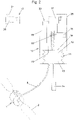
- a band part 1 of the device can be placed in a ring around the body tissue 2 surrounding the body canal, here the urethra.
- the band part 1 has a hollow chamber 3 which extends in the direction of the longitudinal extent of the band part, in the exemplary embodiment essentially over the entire length of the band part.
- the band part 1 is thus formed like a tube with ends closed on both sides.
- the first closure part 4 has an insertion opening 4a into which a tongue 5a of the second closure part 5 can be inserted and latched.
- the closure parts 4, 5 thus form a closure with which the strap part 1 can be closed to form a ring, in particular a circular ring, cf. 3 .
- the strap part 1 encloses a passage opening 6 for the body tissue 2 surrounding the body canal.
- a fluid in particular a liquid, is located in the hollow chamber 3 .
- the size of the passage opening 6 depends on the amount of fluid in the hollow chamber 3 .
- the passage opening 6 can be reduced in size by introducing fluid into the hollow chamber 3 .
- an inner flexible section 1a of the band part 1, i.e. one adjacent to the longitudinal center axis 7 of the passage opening 6, is displaced in the direction of the longitudinal center axis 7, as is known.
- figure 5 shows the state in which the passage opening 6 is at its largest (the pressure of the fluid in the hollow chamber 3 corresponding to the ambient pressure)
- 6 12 shows a state filled with more fluid, in particular the state filled with fluid to the maximum (wherein the pressure of the fluid in the hollow chamber 3 is above the ambient pressure).
- wrinkle formations such as would result in particular if the ligament part is not placed around the ureter, are not shown.
- a back section 1b of the band part 1 remote from the longitudinal center axis 7 can be made stiffer, in particular by means of a reinforcement layer, as a result of which deformation of the back section can be at least largely avoided.
- the body canal could also be narrowed to only different degrees without being completely closed.
- the band part would then therefore assume different states of constriction.
- the band part 1 can consist of silicone in a known manner. In principle, other body-compatible materials can also be used.
- the band part 1 is connected via a hose 9 to a pump part 11 of a pump unit 10 that is locally separate from the band part 1, cf. 1 and 2 .
- the amount of fluid in the hollow chamber 3 of the belt part 1 can be changed by means of the pump unit 10 .
- a connecting piece 8 is formed on one of the closure parts, the interior of which is connected to the hollow chamber 3 via a channel running through the closure part. Such a connecting piece could also be provided at a different location on the hinge part.
- the hose 9 is connected to the connecting piece 8 .
- the pumping part 11 of the pumping unit 10 has a receiving space 12 filled with fluid.
- An electric drive 15 acts on the actuating element 14 via a gear 16 , for example a worm gear, in order to change the volume of the receiving space 12 .
- the gear 16 is advantageously designed to be self-locking, so that a position of the actuating element 14 that has been set once is held without the supply of electrical energy to the drive 15 .
- the pump part 11 also forms a reservoir for the fluid with which the hollow chamber 3 of the band part 1 is filled to close the body canal.
- the pump part 11 could also be formed by a piston-cylinder unit, for example, with the actuating element 14 being formed by the piston of this piston-cylinder unit.
- the pump unit 10 also has an electric drive 15 for the pump part 11 .
- the electric drive 15 is controlled by a pump electronics unit 17 of the pump unit 10 .
- the electronic pump unit 17 is supplied with electrical energy from a battery 18 of the pump unit 10, as is the drive 15.
- the components of the pump unit 10 are arranged in a housing 26 .
- the housing 26 consists of a biocompatible material or is encased by such a material.
- a control unit 19 which is arranged locally separately from the pump unit 10 and has at least one control element 21 that can be actuated by the user, for example a button, is used to adjust the hinge part 1 between the blocked state and the released state. Additional controls can be provided.
- a control electronics unit 20 of the control unit 19 communicates with the pump electronics unit 17 via a radio link.
- the electronic pump unit 17 and the electronic control unit 20 together form the electrical control of the medical device of the invention.
- the operating unit 19 can be arranged outside the body. An implantation of the operating unit 19 is conceivable and possible.
- a battery (not shown in the figures) serves to supply the operating unit 19 with electrical energy.
- a separate control unit could also be omitted, in which case at least one control element that can be actuated by the user would have to be arranged on the pump unit. This would have to be correspondingly operable from outside the body.
- a pressure sensor 22 is connected to the pump electronics unit 17 and is located in the fluid-filled receiving space 12 of the pump part 11 in the exemplary embodiment shown.
- the pressure of the fluid in the receiving space 12 which corresponds to the pressure of the fluid in the hollow chamber 3 , can thus be detected by the electronic controller 17 by means of the pressure sensor 22 .
- an air pressure sensor 23 is connected to the electronic pump unit 17 .
- the ambient pressure which corresponds to the atmospheric pressure, can be detected by the electronic controller 17 .
- the air pressure sensor 23 could also be arranged in the operating unit 19 and the value recorded by it could be transmitted to the electronic pump unit 17 via the radio link.
- a pressure value detected by pressure sensor 22 and an air pressure value detected by air pressure sensor 23 are evaluated in electronic pump unit 17.
- electronic pump unit 17 could also transmit the pressure value detected by pressure sensor 22 to the operating unit 19 arranged electronic control unit 20 are transmitted in order to carry out an evaluation in this. If the air pressure sensor 23 is not arranged in the operating unit 19 , the air pressure value could also be transmitted from the electronic pump unit 17 to the electronic operating unit 20 .
- Recorded pressure values and air pressure values can be stored either in the electronic pump unit 17 or in the electronic control unit 20 .
- the initial adjustment of the pressure of the fluid in the lumen to close the urethra can be done as follows: A catheter can be used to raise the patient from a defined height (e.g. 50 cm). stored vessel water are allowed to flow through the urethra into the bladder, the pressure of the fluid in the hollow chamber 3 is increased until no more water flows through the ureter. Such a method is known under the name "leak point pressure measurement”.
- the pressure value determined in this way is stored as a reference value for the fluid pressure at which the body canal is closed.
- the air pressure value corresponding to the atmospheric pressure detected by the air pressure sensor 23 is stored as the reference value for the atmospheric pressure at which the reference value for the fluid pressure has been determined.
- the pressure value output by the pressure sensor 22 also changes by the same amount.
- the volume of the fluid can change, for example due to osmosis or a leak.
- the fluid volume can also increase due to osmosis.
- the electronic control checks whether the atmospheric pressure and the fluid pressure have changed in the same way. This means that the electronic control determines a first difference between the current pressure value and the reference value of the pressure value and a second difference between the current air pressure value and the reference value of the air pressure value. The first difference and the second difference are compared to one another by the electronic controller. If the first difference and the second difference deviate from one another, then the fluid volume has changed.
- the pressure value determined before the opening of the body canal is stored as the new reference value for the fluid pressure and that detected before the opening of the body canal Barometric pressure value is saved as new reference value for atmospheric pressure.
- the fluid pressure is adjusted to the new fluid pressure reference value (ie, the pressure that existed before the body passage was opened).
- the difference between the change in the Atmospheric pressure and the change in fluid pressure determined (that is, the difference between the first difference and the second difference).
- the atmospheric pressure sensed prior to the opening of the body canal is stored as the new atmospheric pressure reference value.
- the fluid pressure is adjusted to the new fluid pressure reference value.
- the fluid pressure is adjusted by means of the adjusting element 14 of the pump part 14, with the volume of the receiving space 12 of the pump part 11 being reduced or increased accordingly. This setting of the fluid pressure or the fluid volume could also be referred to as readjustment of the fluid pressure.
- the stored reference values could also be retained for a predetermined period of time and only after this predetermined period of time when the body canal is next opened can the described check and, if necessary, correction be carried out.
- a specific change in the fluid volume can thus be inferred from any deviation of the first difference from the second difference. If the fluid volume has changed over a predetermined level, ie over an upper or lower limit value, a warning can be issued.
- a subsequent blocking of the body canal can take place automatically after a certain time or can be triggered by the user, for example by actuating the control element 21 again or by actuating another control element.
- Various adjustments by the user can be made possible, e.g. an increase in the closing pressure of the fluid for a certain time.
- the embodiment according to the invention also enables other types of control of the medical device than those described above.
- a reference fluid pressure and a reference air pressure could be stored and each time the body passageway closes, the reference fluid pressure could be modified by the difference between the current reading of barometric pressure and the reference barometric pressure. This procedure is particularly expedient if a constant volume of the fluid in the system is assumed. A measurement of the fluid pressure and the atmospheric pressure before the opening of the body channel could then be omitted or carried out as a check.
- a port 25 is provided in a conventional manner for filling the system with fluid. This can be connected to the pump part 11 via a hose, for example.
- the pressure sensor 22 in the fluid, it is also conceivable and possible to arrange the pressure sensor on a surface 24 of the band part 1 that delimits the passage opening.
- the pressure exerted on the body tissue is measured directly by the pressure sensor. This pressure naturally depends on the pressure of the fluid in the hollow chamber 3 and is at least largely proportional to it. Deviations from the proportionality are due to a non-linear behavior of the band part 1 when the hollow chamber 3 is enlarged preferably below 10%.
Description
Die Erfindung bezieht sich auf eine medizinische Einrichtung zum Verengen oder Absperren eines Körperkanals, umfassend ein Bandteil, das um das den Körperkanal umgebende Körpergewebe legbar ist und zu einem eine Durchtrittsöffnung für das Körpergewebe umschließenden Ring schließbar ist, wobei das Bandteil eine Hohlkammer aufweist und wobei durch Einbringen eines Fluids in die Hohlkammer die Durchtrittsöffnung verkleinerbar ist, und eine Pumpeinheit zur Förderung des Fluids, welche einen von einer elektronischen Steuerung der Einrichtung ansteuerbaren elektrischen Antrieb aufweist, wobei von der elektronischen Steuerung ein dem Druck des Fluids in der Hohlkammer entsprechender oder von diesem abhängender Druckwert erfassbar ist.The invention relates to a medical device for constricting or blocking a body canal, comprising a strap part which can be placed around the body tissue surrounding the body canal and can be closed to form a ring enclosing a passage opening for the body tissue, the strap part having a hollow chamber and being introduction of a fluid into the hollow chamber, the passage opening can be reduced, and a pump unit for pumping the fluid, which has an electric drive that can be controlled by an electronic controller of the device, with the electronic controller providing a pressure corresponding to or dependent on the pressure of the fluid in the hollow chamber Pressure value can be detected.
Medizinische Einrichtungen zum Verengen oder Absperren eines Körperkanals werden u. a. als künstliche (Schließ)-Muskeln zur Unterstützung oder zum Ersatz von geschwächten natürlichen Muskeln im menschlichen oder tierischen Körper eingesetzt. Beispiele für Einsatzbereiche derartiger Einrichtungen sind Analbänder zum Verschließen eines, gegebenenfalls künstlichen, Anus und künstliche Schließmuskel zur Behandlung von Inkontinenz zum Verschließen der Urethra (=Harnröhre). Weitere Einsatzgebiete sind z.B. Magenbänder zum Verengen des Gastro-Intestinal-Traktes oder Bänder zum Verschließen eines Gangs für Gallenflüssigkeit. Derartige medizinische Einrichtungen werden auch als Cuff, Manschette oder artifizieller Sphinkter bezeichnet.Medical devices for narrowing or closing off a body canal are used i.a. used as artificial (sphincter) muscles to support or replace weakened natural muscles in the human or animal body. Examples of areas in which such devices are used are anal bands for closing an anus, possibly an artificial one, and artificial sphincters for treating incontinence for closing the urethra (=urethra). Other areas of application are e.g. Such medical devices are also referred to as cuffs or artificial sphincters.
Die Hohlkammer kann vom Benutzer bei Bedarf entleert werden, um die Querschnittsfläche der Durchtrittsöffnung zu vergrößern und im Körperkanal enthaltene Stoffe und/oder Flüssigkeiten passieren zu lassen. Z.B. bei der Anwendung als künstlicher Schließmuskel für die Urethra erfolgt häufig ein anschließendes automatisches Verschließen des Körperkanals durch Rückpumpen von Fluid (evtl. über ein Drosselventil) in die Hohlkammer der Einrichtung. Eine Pumpe zum Pumpen von Fluid wird bei einem solchen künstlichen Harnsphinkter für männliche Patienten üblicherweise in das Skrotum implantiert. Das Pumpen von Fluid aus der Hohlkammer kann dann durch Druck auf einen flexiblen Teil der Pumpe erfolgen. Das Rückpumpen von Fluid in die Hohlkammer kann durch ein federelastisches Element der Pumpe erfolgen. Die Durchtrittsöffnung der medizinischen Einrichtung kann häufig auch durch eine bewusste Handlung des Benutzers wieder verkleinert werden, also durch eine manuelle Betätigung der Pumpe.If required, the hollow chamber can be emptied by the user in order to increase the cross-sectional area of the passage opening and to allow substances and/or liquids contained in the body channel to pass through. For example, when used as an artificial sphincter for the urethra, the body canal is then automatically closed by pumping back of fluid (possibly via a throttle valve) into the hollow chamber of the device. In such an artificial urinary sphincter for male patients, a pump for pumping fluid is usually implanted in the scrotum. Pumping of fluid from the lumen can then be accomplished by pressure on a flexible portion of the pump. Fluid can be pumped back into the hollow chamber by a spring-elastic element of the pump. The passage opening of the medical device can often also be made smaller again by a conscious action on the part of the user, ie by manually actuating the pump.
Z.B. aus der
Bekannt sind weiters implantierbare medizinische Einrichtungen, durch welche ein flüssiges Medikament an einen gewünschten Ort innerhalb des Körpers dosiert werden kann. Aus der
Eine Einrichtung der eingangs genannten Art geht aus der
Aus der
Medizinische Einrichtungen zur Beeinflussung des Durchflusses des Darmtrakts und zur Stimulation einer Kontraktion des Darmes sind in der
Aufgabe der Erfindung ist es, eine Einrichtung der eingangs genannten Art bereitzustellen, die einen verbesserten Betrieb ermöglicht. Erfindungsgemäß gelingt dies durch eine Einrichtung mit den Merkmalen des Anspruchs 1.The object of the invention is to provide a device of the type mentioned at the outset that enables improved operation. According to the invention, this is achieved by a device with the features of
Die Einrichtung gemäß der Erfindung weist einen Luftdrucksensor auf. Von der elektronischen Steuerung ist somit ein von diesem Luftdrucksensor ausgegebener Luftdruckwert erfassbar, der dem Atmosphärendruck entspricht. Insbesondere kann von der Steuerung unter Heranziehung von zu verschiedenen Zeitpunkten erfassten Druckwerten, die dem jeweiligen Druck des Fluids in der Hohlkammer entsprechen oder von diesem abhängen, und von erfassten Luftdruckwerten, die dem jeweiligen Atmosphärendruck entsprechen, eine Änderung des Fluidvolumens im System festgestellt und gegebenenfalls der eingestellte Druck für das Fluid daran angepasst werden und/oder im Falle einer Überschreitung eines oberen oder unteren Grenzwerts für das festgestellte Flüssigkeitsvolumen eine Warnung ausgegeben werden.The device according to the invention has an air pressure sensor. An air pressure value output by this air pressure sensor, which corresponds to atmospheric pressure, can thus be detected by the electronic control. In particular, the controller can change the fluid volume in the system using pressure values recorded at different points in time, which correspond to or depend on the respective pressure of the fluid in the hollow chamber, and recorded air pressure values which correspond to the respective atmospheric pressure determined and, if necessary, the set pressure for the fluid can be adjusted to it and/or a warning can be issued if an upper or lower limit value for the determined liquid volume is exceeded.
Eine solche Änderung des Flüssigkeitsvolumens kann beispielsweise durch Osmose oder durch ein Leck hervorgerufen werden.Such a change in the liquid volume can be caused, for example, by osmosis or by a leak.
Durch die erfindungsgemäße Einrichtung können vorteilhafterweise optimale Druckverhältnisse an der Harnröhre erzielt werden.The device according to the invention advantageously makes it possible to achieve optimal pressure conditions in the urethra.
Ein dem Druck des Fluids in der Hohlkammer entsprechender Druckwert kann in einer möglichen Ausbildungsform mittels eines im Fluid angeordneten Drucksensors erfasst werden.In one possible embodiment, a pressure value corresponding to the pressure of the fluid in the hollow chamber can be detected by means of a pressure sensor arranged in the fluid.
Auch eine Anordnung eines Drucksensors an einer die Durchtrittsöffnung begrenzenden Oberfläche des Bandteils ist denkbar und möglich. Ein von einem solchen Drucksensor erfasster Druckwert hängt jedenfalls vom Druck des Fluids in der Hohlkammer ab und kann vorzugsweise zum Druck des Fluids in der Hohlkammer zumindest im Wesentlichen proportional sein.It is also conceivable and possible to arrange a pressure sensor on a surface of the belt part that delimits the passage opening. A pressure value detected by such a pressure sensor depends in any case on the pressure of the fluid in the hollow chamber and can preferably be at least essentially proportional to the pressure of the fluid in the hollow chamber.
Ein Druckwert könnte auch mittels eines Dehnmessstreifens gemessen werden, der auf eine Membran geklebt ist, die sich aufgrund von Druckschwankungen verformt. Die Membran begrenzt einen Raum in welchem sich das Fluid befindet. Beispielsweise könnte die Membran auch von einem Abschnitt des Bandteils selbst gebildet werden. Es wird durch eine solche Membran mit einem aufgeklebten Dehnmessstreifen ein Drucksensor ausgebildet, der an das Fluid angrenzt. Auch ein durch einen auf diese Weise ausgebildeten Drucksensor erfasster Druckwert hängt jedenfalls vom Druck des Fluids in der Hohlkammer ab und kann vorzugsweise zum Druck des Fluids in der Hohlkammer zumindest im Wesentlichen proportional sein.A pressure value could also be measured using a strain gauge glued to a membrane that deforms due to pressure fluctuations. The membrane delimits a space in which the fluid is located. For example, the membrane could also be formed by a section of the band part itself. A pressure sensor is formed by such a membrane with a bonded strain gauge, which is adjacent to the fluid. A pressure value detected by a pressure sensor designed in this way also depends on the pressure of the fluid in the hollow chamber and can preferably be at least substantially proportional to the pressure of the fluid in the hollow chamber.
Je nach eingesetztem elektrischem Antrieb könnte ein dem Druck des Fluids in der Hohlkammer entsprechender oder von diesem abhängender Druckwert auch aus der Stromaufnahme des elektrischen Antriebs der Pumpeinrichtung abgeleitet werden.Depending on the electric drive used, a pressure value corresponding to or dependent on the pressure of the fluid in the hollow chamber could also be derived from the power consumption of the electric drive of the pump device.
Eine vorteilhafte Ausführungsform sieht vor, dass die Pumpeinheit ein Pumpteil aufweist, das einen mit dem Fluid befüllten Aufnahmeraum besitzt, dessen Volumen mittels des Antriebs veränderbar ist. Beispielsweise kann das Pumpteil ein von einem durch ein Bodenteil und ein Deckelteil verschlossener Balg sein. Auch eine Ausbildung des Pumpteils in Form einer Kolben-Zylinder-Einheit ist denkbar und möglich. Der Drucksensor zur Erfassung des Drucks des Fluids in der Hohlkammer des Bandteils kann in einem solchen Aufnahmeraum eines Pumpteils angeordnet sein. Auch eine Anordnung direkt in der Hohlkammer des Bandteils oder im Kanal eines das Bandteil mit dem Pumpteil verbindenden Schlauchs ist denkbar und möglich.An advantageous embodiment provides that the pump unit is a pump part has, which has a receiving space filled with the fluid, the volume of which can be changed by means of the drive. For example, the pump part can be a bellows closed by a base part and a cover part. A configuration of the pump part in the form of a piston-cylinder unit is also conceivable and possible. The pressure sensor for detecting the pressure of the fluid in the hollow chamber of the belt part can be arranged in such a receiving space of a pump part. An arrangement directly in the hollow chamber of the belt part or in the channel of a hose connecting the belt part to the pump part is also conceivable and possible.
Vorzugweise weist die Einrichtung eine von der Pumpeinheit (und vom Bandteil) örtlich getrennte Bedieneinheit auf, welche mindestens ein von einem Benutzer betätigbares Bedienelement aufweist, um den Körperkanal zu öffnen und/oder abzusperren. Die Bedieneinheit weist hierbei vorteilhafterweise eine Bedien-Elektronikeinheit auf, welche mit einer Pump-Elektronikeinheit der Pumpeinheit über eine Funkverbindung kommuniziert. Diese Bedieneinheit kann außerhalb des Körpers vorgesehen sein. Auch eine Implantation der Bedieneinheit, und zwar unabhängig vom Ort der Implantation des Bandteils und der Pumpeinheit, ist denkbar und möglich.The device preferably has an operating unit that is locally separate from the pump unit (and from the band part) and has at least one operating element that can be actuated by a user in order to open and/or shut off the body canal. In this case, the operating unit advantageously has an operating electronics unit which communicates with a pump electronics unit of the pump unit via a radio link. This operating unit can be provided outside the body. It is also conceivable and possible to implant the operating unit, specifically independently of the location of the implantation of the band part and the pump unit.
Der Luftdrucksensor kann in der (implantierten oder außerhalb des Körpers angeordneten) Bedieneinheit angeordnet sein. Auch eine Anordnung des Luftdrucksensors in der Pumpeinheit ist möglich.The air pressure sensor can be arranged in the operating unit (implanted or arranged outside the body). An arrangement of the air pressure sensor in the pump unit is also possible.
Die Einrichtung kann beispielsweise als künstlicher Urethrasphinkter ausgebildet sein. In anderen Ausführungsformen kann die erfindungsgemäße Einrichtung z.B. als künstlicher Analsphinkter, künstlicher "Sphinkter of oddi" oder künstlicher Verschluss eines Gangs für Gallenflüssigkeit ausgebildet sein.The device can be designed, for example, as an artificial urethral sphincter. In other embodiments, the device according to the invention can be designed, for example, as an artificial anal sphincter, artificial "sphincter of oddi" or artificial closure of a bile duct.
Das Absperren des Körperkanals kann vollständig oder teilweise (=Verengen) erfolgen.The blocking of the body canal can be complete or partial (= narrowing).
Weitere Vorteile und Einzelheiten der Erfindung werden im Folgenden anhand der beiliegenden Zeichnung erläutert. In dieser zeigen:
-
Fig. 1 eine schematische Darstellung einer als künstlicher Urethrasphinkter ausgebildeten Einrichtung, in einem Freigabezustand des Bandteils, in welchem der Harnleiter geöffnet ist; -
Fig. 2 eine Darstellung analogFig. 1 in einem Absperrzustand des Bandteils, in welchem der Harnleiter geschlossen ist; -
Fig. 3 und 4 Schrägsichten des freien, also nicht implantierten, Bandteils der Einrichtung in einem geöffneten und geschlossenen Zustand, und zwar entsprechend dem Freigabezustand; -
Fig. 5 einen Längsmittelschnitt (parallel zur Längsmittelachse der Durchtrittsöffnung und diese durchsetzend) durch das Bandteil im Zustand vonFig. 4 und -
Fig. 6 einen Längsmittelschnitt analogFig. 5 , aber im Absperrzustand des Bandteils.
-
1 a schematic representation of a device designed as an artificial urethral sphincter, in a release state of the ligament part in which the ureter is open; -
2 a representation analogous1 in a blocking state of the ligament part in which the ureter is closed; -
Figures 3 and 4 Oblique views of the free, ie non-implanted, ligament part of the device in an open and closed state, in accordance with the release state; -
figure 5 a longitudinal central section (parallel to the longitudinal central axis of the passage opening and passing through) through the band part in the state of4 and -
6 a longitudinal midsection analogousfigure 5 , but in the lock state of the band part.
Ein Ausführungsbeispiel einer erfindungsgemäßen Einrichtung ist in den Figuren dargestellt.An embodiment of a device according to the invention is shown in the figures.
Ein Bandteil 1 der Einrichtung ist ringförmig um das den Körperkanal umgebende Körpergewebe 2, hier die Harnröhre, legbar. Das Bandteil 1 weist eine Hohlkammer 3 auf, die sich in Richtung der Längserstreckung des Bandteils erstreckt, im Ausführungsbeispiel im Wesentlichen über die gesamte Länge des Bandteils. Das Bandteil 1 ist somit schlauchartig ausgebildet mit beidseitig verschlossenen Enden.A
An den beiden Enden des Bandteils 1 sind ein erstes und ein zweites Verschlussteil 4, 5 angeordnet. Das erste Verschlussteil 4 besitzt eine Einstecköffnung 4a, in welche eine Zunge 5a des zweiten Verschlussteils 5 einsteckbar und darin verrastbar ist.At the two ends of the
Die Verschlussteile 4, 5 bilden somit einen Verschluss, mit welchem das Bandteil 1 zu einem Ring, insbesondere Kreisring, geschlossen werden kann, vgl.
In der Hohlkammer 3 befindet sich ein Fluid, insbesondere eine Flüssigkeit. Die Größe der Durchtrittsöffnung 6 hängt von der Menge des Fluids in der Hohlkammer 3 ab. Durch Einbringen von Fluid in die Hohlkammer 3 kann die Durchtrittsöffnung 6 verkleinert werden. Hierbei wird ein innerer, d.h. der Längsmittelachse 7 der Durchtrittsöffnung 6 benachbarter, flexibler Abschnitt 1a des Bandteils 1 in Richtung zur Längsmittelachse 7 verschoben, wie dies bekannt ist. Durch Abführen von Fluid aus der Hohlkammer 3 kann die Durchtrittsöffnung 6 wieder vergrößert werden.A fluid, in particular a liquid, is located in the
Ein von der Längsmittelachse 7 abgelegener Rückenabschnitt 1b des Bandteils 1 kann demgegenüber steifer ausgebildet sein, insbesondere mittels einer Verstärkungslage, wodurch eine Verformung des Rückenabschnitts zumindest weitgehend vermieden werden kann.In contrast, a
Im geschlossenen Zustand des Bandteils 1 kann dieses also einen Freigabezustand, in welchem der Körperkanal geöffnet ist (vgl.
In anderen Ausführungsformen der Erfindung könnte der Körperkanal auch nur unterschiedlich stark verengt werden, ohne vollständig geschlossen zu werden. Das Bandteil würde dann also unterschiedliche Verengungszustände einnehmen.In other embodiments of the invention, the body canal could also be narrowed to only different degrees without being completely closed. The band part would then therefore assume different states of constriction.
Unterschiedliche Modifikationen der Ausbildung des Bandteils sind denkbar und möglich, so wäre es beispielsweise möglich, spezielle am Bandteil 1 angebrachte Verschlussteile überhaupt wegzulassen und die beiden Enden des Bandteils miteinander zu vernähen.Different modifications of the design of the strap part are conceivable and possible, for example it would be possible to omit special closure parts attached to the
Das Bandteil 1 kann in bekannter Weise aus Silikon bestehen. Auch andere körperverträgliche Materialien sind grundsätzlich einsetzbar.The
Das Bandteil 1 steht über einen Schlauch 9 mit einem vom Bandteil 1 örtlich getrennten Pumpteil 11 einer Pumpeinheit 10 in Verbindung, vgl.
Im Ausführungsbeispiel ist an einem der Verschlussteile ein Anschlussstutzen 8 angeformt, dessen Innenraum über einen durch das Verschlussteil laufenden Kanal mit der Hohlkammer 3 in Verbindung steht. Ein solcher Anschlussstutzen könnte auch an einer anderen Stelle des Bandteils vorgesehen sein. Der Schlauch 9 ist am Anschlussstutzen 8 angeschlossen.In the exemplary embodiment, a connecting
Das Pumpteil 11 der Pumpeinheit 10 besitzt einen mit Fluid befüllten Aufnahmeraum 12. Im Ausführungsbeispiel wird das Pumpteil 11 von einem Balg gebildet, der von einem Bodenteil 13 und einem Deckelteil, welches ein Stellelement 14 darstellt, verschlossen ist. Ein elektrischer Antrieb 15 wirkt über ein Getriebe 16, beispielsweise Schneckengetriebe, auf das Stellelement 14 ein, um das Volumen des Aufnahmeraums 12 zu ändern. Das Getriebe 16 ist günstigerweise selbsthemmend ausgebildet, sodass eine einmal eingestellte Position des Stellelements 14 ohne Zufuhr von elektrischer Energie an den Antrieb 15 gehalten wird.The pumping
Das Pumpteil 11 bildet im Ausführungsbeispiel also gleichzeitig ein Reservoir für das Fluid, mit welchem die Hohlkammer 3 des Bandteils 1 zum Schließen des Körperkanals befüllt wird.In the exemplary embodiment, the
Das Pumpteil 11 könnte beispielsweise auch von einer Kolben-Zylinder-Einheit gebildet werden, wobei das Stellelement 14 vom Kolben dieser Kolben-Zylinder-Einheit gebildet würde.The
Die Pumpeinheit 10 besitzt im Weiteren einen elektrischen Antrieb 15 für das Pumpteil 11. Der elektrische Antrieb 15 wird von einer Pump-Elektronikeinheit 17 der Pumpeinheit 10 angesteuert. Die Pump-Elektronikeinheit 17 wird aus einer Batterie 18 der Pumpeinheit 10 mit elektrischer Energie versorgt, ebenso wie der Antrieb 15. Bei der Batterie 18 kann es sich insbesondere um eine wiederaufladbare Batterie (=Akkumulator) handeln. Die Aufladung könnte hierbei berührungslos durch ein außerhalb des Körpers angeordnetes induktiv gekoppeltes Ladegerät erfolgen.The
Die Komponenten der Pumpeinheit 10 sind in einem Gehäuse 26 angeordnet. Das Gehäuse 26 besteht aus einem körperverträglichen Material oder ist von einem solchen umhüllt.The components of the
Zur Verstellung des Bandteils 1 zwischen dem Absperrzustand und dem Freigabezustand dient eine von der Pumpeinheit 10 örtlich getrennt angeordnete Bedieneinheit 19, die mindestens ein vom Benutzer betätigbares Bedienelement 21, beispielsweise einen Taster, aufweist. Weitere Bedienelemente können vorgesehen sein. Eine Bedien-Elektronikeinheit 20 der Bedieneinheit 19 kommuniziert hierbei mit der Pump-Elektronikeinheit 17 über eine Funkverbindung.A
Die Pump-Elektronikeinheit 17 und die Bedien-Elektronikeinheit 20 bilden zusammen die elektrische Steuerung der medizinischen Einrichtung der Erfindung.The
Die Bedieneinheit 19 kann außerhalb des Körpers angeordnet sein. Eine Implantation der Bedieneinheit 19 ist denkbar und möglich.The operating
Zur Versorgung der Bedieneinheit 19 mit elektrischer Energie dient eine (in den Figuren nicht dargestellte) Batterie.A battery (not shown in the figures) serves to supply the
Eine separate Bedieneinheit könnte grundsätzlich auch entfallen, wobei mindestens ein vom Benutzer betätigbares Bedienelement an der Pumpeinheit anzuordnen wäre. Dieses müsste entsprechend von außerhalb des Körpers betätigbar sein.In principle, a separate control unit could also be omitted, in which case at least one control element that can be actuated by the user would have to be arranged on the pump unit. This would have to be correspondingly operable from outside the body.
Mit der Pump-Elektronikeinheit 17 ist ein Drucksensor 22 verbunden, der sich im gezeigten Ausführungsbeispiel im mit Fluid gefüllten Aufnahmeraum 12 des Pumpteils 11 befindet. Mittels des Drucksensors 22 ist somit von der elektronischen Steuerung 17 der Druck des Fluids im Aufnahmeraum 12 erfassbar, der dem Druck des Fluids in der Hohlkammer 3 entspricht.A
Mit der Pump-Elektronikeinheit 17 ist im Weiteren ein Luftdrucksensor 23 verbunden. Mittels diesem kann von der elektronischen Steuerung 17 der Umgebungsdruck erfasst werden, der dem Atmosphärendruck entspricht. Der Luftdrucksensor 23 könnte auch in der Bedieneinheit 19 angeordnet werden und der von ihm erfasste Wert könnte über die Funkverbindung an die Pump-Elektronikeinheit 17 übertragen werden. Die Auswertung eines mittels des Drucksensors 22 erfassten Druckwerts und eines mittels des Luftdrucksensors 23 erfassten Luftdruckwerts erfolgt im Ausführungsbeispiel also in der Pump-Elektronikeinheit 17. Andererseits könnte von der Pump-Elektronikeinheit 17 auch der mittels des Drucksensors 22 erfasste Druckwert an die in der Bedieneinheit 19 angeordnete Bedien-Elektronikeinheit 20 übertragen werden, um in dieser eine Auswertung durchzuführen. Wenn der Luftdrucksensor 23 nicht in der Bedieneinheit 19 angeordnet ist, könnte in diesem Fall auch der Luftdruckwert von der Pump-Elektronikeinheit 17 an die Bedien-Elektronikeinheit 20 übertragen werden.Furthermore, an
Eine Speicherung von erfassten Druckwerten und Luftdruckwerten kann wahlweise in der Pump-Elektronikeinheit 17 oder Bedien-Elektronikeinheit 20 erfolgen.Recorded pressure values and air pressure values can be stored either in the
Die erstmalige Einstellung des Drucks des Fluids in der Hohlkammer, um die Harnröhre zu schließen, kann folgendermaßen durchgeführt werden:
Mittels eines Katheters kann aus einem in definierter Höhe (z.B. 50cm) erhöht gelagerten Gefäß Wasser durch die Harnröhre in die Blase einfließen gelassen werden, wobei der Druck des Fluids in der Hohlkammer 3 erhöht wird, bis kein Wasser mehr durch den Harnleiter fließt. Ein solches Verfahren ist unter der Bezeichnung "Leak-Point-Pressure-Messung" bekannt.The initial adjustment of the pressure of the fluid in the lumen to close the urethra can be done as follows:
A catheter can be used to raise the patient from a defined height (e.g. 50 cm). stored vessel water are allowed to flow through the urethra into the bladder, the pressure of the fluid in the
Der so ermittelte Druckwert wird als Referenzwert für den Fluiddruck gespeichert, bei welchem der Körperkanal geschlossen ist. Gleichzeitig wird der dem Atmosphärendruck entsprechende, vom Luftdrucksensor 23 erfasste Luftdruckwert als Referenzwert für den Atmosphärendruck gespeichert, bei welchem der Referenzwert für den Fluiddruck ermittelt worden ist.The pressure value determined in this way is stored as a reference value for the fluid pressure at which the body canal is closed. At the same time, the air pressure value corresponding to the atmospheric pressure detected by the
Wenn nun der Körperkanal durch Beaufschlagen der Hohlkammer mit diesem Referenzwert für den Fluiddruck geschlossen worden ist und sich bei gleichbleibendem Volumen des Fluids der Atmosphärendruck ändert, so ändert sich auch der vom Drucksensor 22 ausgegebene Druckwert um den gleichen Betrag.If the body channel has now been closed by applying this reference value for the fluid pressure to the hollow chamber and the atmospheric pressure changes while the volume of the fluid remains the same, the pressure value output by the
Im Laufe der Zeit kann es beispielsweise durch Osmose oder durch ein Leck zu einer Änderung des Volumens des Fluids kommen. Durch Osmose kann das Fluidvolumen hierbei auch zunehmen. Vor einer jeweiligen Öffnung des Körperkanals wird von der elektronischen Steuerung hierzu überprüft, ob sich der Atmosphärendruck und der Fluiddruck in gleicher Weise geändert haben. Das heißt also, dass mittels der elektronischen Steuerung eine erste Differenz zwischen dem aktuellen Druckwert und dem Referenzwert des Druckwerts und eine zweite Differenz zwischen dem aktuellen Luftdruckwert und dem Referenzwert des Luftdruckwerts ermittelt werden. Die erste Differenz und die zweite Differenz werden mittels der elektronischen Steuerung miteinander verglichen. Sollten die erste Differenz und die zweite Differenz voneinander abweichen, so hat sich das Fluidvolumen geändert.Over time, the volume of the fluid can change, for example due to osmosis or a leak. The fluid volume can also increase due to osmosis. Before each opening of the body channel, the electronic control checks whether the atmospheric pressure and the fluid pressure have changed in the same way. This means that the electronic control determines a first difference between the current pressure value and the reference value of the pressure value and a second difference between the current air pressure value and the reference value of the air pressure value. The first difference and the second difference are compared to one another by the electronic controller. If the first difference and the second difference deviate from one another, then the fluid volume has changed.
Wenn die erste Differenz und die zweite Differenz nicht voneinander abweichen, d.h. die erste Differenz und die zweite Differenz stimmen überein, wird der vor dem Öffnen des Körperkanals ermittelte Druckwert als neuer Referenzwert für den Fluiddruck gespeichert und der vor dem Öffnen des Körperkanals erfasste Luftdruckwert wird als neuer Referenzwert für den Atmosphärendruck gespeichert. Beim neuerlichen Schließen des Körperkanals wird der Fluiddruck auf den neuen Referenzwert für den Fluiddruck eingestellt (d.h. auf den Druck, der vor dem Öffnen des Körperkanals vorgelegen ist).If the first difference and the second difference do not differ from each other, ie the first difference and the second difference are the same, the pressure value determined before the opening of the body canal is stored as the new reference value for the fluid pressure and that detected before the opening of the body canal Barometric pressure value is saved as new reference value for atmospheric pressure. Upon re-closing the body passage, the fluid pressure is adjusted to the new fluid pressure reference value (ie, the pressure that existed before the body passage was opened).
Sollte es aber zu einer Abweichung der ersten Differenz von der zweiten Differenz, und damit zu einer Veränderung des Fluidvolumens, gekommen sein, d.h. die erfassten Werte für den Fluiddruck und den Atmosphärendruck haben sich nicht gleich viel geändert, so wird die Differenz zwischen der Änderung des Atmosphärendrucks und der Änderung des Fluiddrucks ermittelt (also der Unterschied zwischen der ersten Differenz und der zweiten Differenz). Als neuer Referenzwert für den Fluiddruck wird die Summe aus dem vor dem Öffnen des Körperkanals ermittelten Druckwert und der genannten Differenz (=Unterschied zwischen der ersten Differenz und der zweiten Differenz) gespeichert. Der vor dem Öffnen des Körperkanals erfasste Atmosphärendruck wird als neuer Referenzwert für den Atmosphärendruck gespeichert. Beim neuerlichen Schließen des Körperkanals wird der Fluiddruck auf den neuen Referenzwert für den Fluiddruck eingestellt. Die Einstellung des Fluiddrucks wird mittels des Stellelements 14 des Pumpteils 14 vorgenommen, wobei das Volumen des Aufnahmeraums 12 des Pumpteils 11 entsprechend verkleinert oder vergrößert wird. Diese Einstellung des Fluiddrucks bzw. des Fluidvolumens könnte auch als Nachregelung des Fluiddrucks bezeichnet werden.However, if the first difference deviates from the second difference, and thus the fluid volume has changed, i.e. the recorded values for the fluid pressure and the atmospheric pressure have not changed by the same amount, then the difference between the change in the Atmospheric pressure and the change in fluid pressure determined (that is, the difference between the first difference and the second difference). The sum of the pressure value determined before the opening of the body canal and the stated difference (=difference between the first difference and the second difference) is stored as the new reference value for the fluid pressure. The atmospheric pressure sensed prior to the opening of the body canal is stored as the new atmospheric pressure reference value. Upon re-closing the body passage, the fluid pressure is adjusted to the new fluid pressure reference value. The fluid pressure is adjusted by means of the adjusting
Dieser Vorgang kann bei jedem Öffnen des Körperkanals wiederholt werden. Es könnten aber auch für einen vorgegebenen Zeitraum die gespeicherten Referenzwerte beibehalten werden und erst nach diesem vorgegebenen Zeitraum beim nächsten Öffnen des Körperkanals die beschriebene Überprüfung und gegebenenfalls Korrektur durchgeführt werden.This process can be repeated each time the body canal is opened. However, the stored reference values could also be retained for a predetermined period of time and only after this predetermined period of time when the body canal is next opened can the described check and, if necessary, correction be carried out.
Aus jeder Abweichung der ersten Differenz von der zweiten Differenz kann somit auf eine bestimmte Änderung des Fluidvolumens geschlossen werden. Falls sich das Fluidvolumen über ein vorgegebenes Maß geändert hat, also über einen oberen oder unteren Grenzwert hinaus, kann eine Warnung ausgegeben werden.A specific change in the fluid volume can thus be inferred from any deviation of the first difference from the second difference. If the fluid volume has changed over a predetermined level, ie over an upper or lower limit value, a warning can be issued.
Ein jeweiliges Öffnen (=Freigeben) des Körperkanals kann vom Benutzer durch einen Druck auf das Bedienelement 21 ausgelöst werden. Ein folgendes Absperren des Körperkanals kann nach einer bestimmten Zeit automatisch erfolgen oder durch den Benutzer ausgelöst werden, beispielsweise durch neuerliche Betätigung des Bedienelements 21 oder durch Betätigung eines anderen Bedienelements. Verschiedene Einstellungen durch den Benutzer können ermöglicht werden, z.B. eine Erhöhung des Schließdrucks des Fluids für eine bestimmte Zeit.A respective opening (=release) of the body channel can be triggered by the user by pressing the
Die erfindungsgemäße Ausbildung ermöglicht auch andere Arten der Steuerung der medizinischen Einrichtung als die zuvor beschriebene. So könnten ein Referenzwert für den Fluiddruck und ein Referenzwert für den Luftdruck gespeichert sein und bei jedem Schließvorgang des Körperkanals könnte der Referenzwert für den Fluiddruck modifiziert um die Differenz zwischen dem aktuellen Messwert des Luftdrucks und dem Referenzwert des Luftdrucks eingestellt werden. Diese Vorgehensweise ist insbesondere dann zweckmäßig, wenn von einem konstanten Volumen des Fluids im System ausgegangen wird. Eine Messung des Fluiddrucks und des Atmosphärendrucks vor dem Öffnen des Körperkanals könnte dann entfallen oder zur Kontrolle durchgeführt werden.The embodiment according to the invention also enables other types of control of the medical device than those described above. Thus, a reference fluid pressure and a reference air pressure could be stored and each time the body passageway closes, the reference fluid pressure could be modified by the difference between the current reading of barometric pressure and the reference barometric pressure. This procedure is particularly expedient if a constant volume of the fluid in the system is assumed. A measurement of the fluid pressure and the atmospheric pressure before the opening of the body channel could then be omitted or carried out as a check.
Zum Befüllen des Systems mit Fluid ist in herkömmlicher Weise ein Port 25 vorhanden. Dieser kann beispielsweise über einen Schlauch an das Pumpteil 11 angeschlossen sein.A
Anstelle einer Anordnung des Drucksensors 22 im Fluid ist es auch denkbar und möglich, den Drucksensor an einer die Durchtrittsöffnung begrenzenden Oberfläche 24 des Bandteils 1 anzuordnen. Es wird vom Drucksensor damit direkt der auf das Körpergewebe ausgeübte Druck gemessen. Dieser Druck hängt natürlich vom Druck des Fluids in der Hohlkammer 3 ab und ist zumindest weitgehend proportional zu diesem. Abweichungen von der Proportionalität aufgrund von einem nicht linearen Verhalten des Bandteils 1 bei einer Vergrößerung der Hohlkammer 3 liegen vorzugsweise unter 10%.Instead of arranging the
In Abhängigkeit von der Art des Antriebs 15 könnte es auch möglich sein, aus der Stromaufnahme des Antriebs 15 auf die Größe des Fluiddrucks zu schließen. Ein Drucksensor zur Erfassung des Drucks des Fluids könnte damit entfallen.
Claims (15)
- A medical device for the narrowing or blocking of an anatomical channel, comprising- a band part (1) which can be placed around the body tissue (2) surrounding the anatomical channel and is closeable to form a ring enclosing a through opening (6) for the body tissue, wherein the band part (1) has a hollow chamber (3) and wherein the through opening (6) can be reduced in size by the introduction of a fluid into the hollow chamber (3), and- a pumping unit (10), for conveying the fluid, which has an electric drive (15) controllable by an electronic control means of the device, wherein a pressure value corresponding to the pressure of the fluid in the hollow chamber (3) or dependent thereon can be detected by the electronic control means,characterised in that the device has an air pressure sensor (23) for detecting the atmospheric pressure, and in that a reference value of the pressure value detected by the electronic control means as well as a reference value of an air pressure value detected by the electronic control means by means of the air pressure sensor (23) can be stored by the electronic control means, wherein dependent on the stored reference value of the pressure value and on the stored reference value of the air pressure value, the pressure of the fluid in the hollow chamber (3) is adjustable by means of the electronic control means to narrow or block the anatomical channel.
- A medical device according to claim 1, characterised in that the device has a pressure sensor (22) which is arranged in the fluid or adjacent to the fluid or at a surface (24), bounding the through opening (6), of the band part (1).
- A medical device according to claim 1 or 2, characterised in that the device has an operating unit (19) arranged spatially separated from the pumping unit (10), wherein the pumping unit (10) has a pump electronic unit (17) and the operating unit (19) has an operating electronic unit (20) and the electronic control means of the device comprises the pump electronic unit (17) and the operating electronic unit (20) and the pump electronic unit (17) and the operating electronic unit (20) communicate via a radio connection.
- A medical device according to any one of claims 1 to 3, characterised in that the pumping unit (10) has a pump part (11) which has a receiving chamber (12) which is filled with the fluid and whose volume is alterable by means of the drive (15).
- A medical device according to claim 4, characterised in that the pump part (11) has bellows.
- A medical device according to claim 4 or 5, characterised in that an adjustment element (14) of the pump part (11) is adjustable by the drive (15), wherein the volume of the receiving chamber (12) of the pump part (11) alters upon adjustment of the adjustment element (14).
- A medical device according to any one of claims 1 to 6, characterised in that the pumping unit (10) has a battery (18) to supply the drive (15) with electrical energy.
- A medical device according to any one of claims 1 to 7, characterised in that a first quantitative difference between an actual pressure value and the stored reference value of the pressure value and a second quantitative difference between an actual air pressure value and the stored reference value of the air pressure can be determined by the electronic control means, and in that a difference between the first quantitative difference and the second quantitative difference can be determined by the electronic control means.
- A medical device according to claim 8, characterised in that in the event of a difference between the first quantitative difference and the second quantitative difference, the sum of the pressure value determined before an opening of the anatomical channel and of the difference between the first quantitative difference and the second quantitative difference can be stored as a new reference value for the pressure value, and in that the air pressure value determined before the opening of the anatomical channel can be stored as a new reference value for the air pressure.
- A medical device according to claim 8, characterised in that in the event of an agreement of the first quantitative difference and the second quantitative difference, the pressure value determined before an opening of the anatomical channel can be stored as a new reference value for the pressure value and the air pressure value detected before the opening of the anatomical channel can be stored as a new reference value for the air pressure value.
- A medical device according to claim 9 or 10, characterised in that the pressure of the fluid in the hollow chamber (3) is adjustable to the new reference value of the pressure value by means of the electronic control means.
- A medical device according to any one of claims 1 to 11, characterised in that the medical device is an artificial urethral sphincter.
- A method of monitoring a fluid volume of a medical device, fillable with a fluid, for blocking and unblocking an anatomical channel, comprising- a band part (1) which can be placed around the body tissue (2) surrounding the anatomical channel and is closeable to form a ring enclosing a through opening (6) for the body tissue, wherein the band part (1) has a hollow chamber (3) fillable with fluid to reduce the size of the through opening (6), and- a pumping unit (10), for conveying the fluid, which has an electric drive (15) controllable by an electronic control means of the device, wherein a pressure value corresponding to the pressure of the fluid in the hollow chamber (3) or dependent thereon can be detected by the electronic control means,characterised in that the device has an air pressure sensor (23) for detecting the atmospheric pressure, and an air pressure value emitted by the air pressure sensor (23) can be detected by the electronic control means, wherein a reference value of the pressure value detected by the electronic control means as well as a reference value of the air pressure value detected by the electronic control means by means of the air pressure sensor (23) are stored in the electronic control means, and wherein an actual pressure value is detected by the electronic control means before the specific unblocking of the anatomical channel and an actual air pressure value is detected by the electronic control means by means of the air pressure sensor (23), and wherein a first quantitative difference between the actual pressure value and the reference value of the pressure value and a second quantitative difference between the actual air pressure value and the reference value of the air pressure value are formed by means of the electronic control means and through comparison of the first quantitative difference and the second quantitative difference by means of the electronic control means there is inferred an alteration in the fluid volume.
- A method according to claim 13, characterised in that a change in the fluid volume is inferred from a divergence of the first quantitative difference from the second quantitative difference.
- A method according to claim 14, characterised in that an alarm is emitted in the event of a change in the fluid volume beyond an upper and/or lower threshold value.
Applications Claiming Priority (2)
| Application Number | Priority Date | Filing Date | Title |
|---|---|---|---|
| ATA274/2016A AT518714B1 (en) | 2016-06-03 | 2016-06-03 | Medical device for narrowing or shutting off a body canal |
| PCT/AT2017/000042 WO2017205883A1 (en) | 2016-06-03 | 2017-05-29 | Medical device for narrowing or closing an anatomical channel |
Publications (2)
| Publication Number | Publication Date |
|---|---|
| EP3463182A1 EP3463182A1 (en) | 2019-04-10 |
| EP3463182B1 true EP3463182B1 (en) | 2022-09-14 |
Family
ID=59054914
Family Applications (1)
| Application Number | Title | Priority Date | Filing Date |
|---|---|---|---|
| EP17729750.4A Active EP3463182B1 (en) | 2016-06-03 | 2017-05-29 | Medical device for narrowing or closing an anatomical channel |
Country Status (7)
| Country | Link |
|---|---|
| US (1) | US11197748B2 (en) |
| EP (1) | EP3463182B1 (en) |
| CN (1) | CN109414314B (en) |
| AT (1) | AT518714B1 (en) |
| BR (1) | BR112018074570B1 (en) |
| ES (1) | ES2928620T3 (en) |
| WO (1) | WO2017205883A1 (en) |
Families Citing this family (9)
| Publication number | Priority date | Publication date | Assignee | Title |
|---|---|---|---|---|
| AT518764B1 (en) | 2016-06-14 | 2018-03-15 | Ami Agency Medical Innovations Gmbh | Medical device for shutting off a body canal |
| AT518411B1 (en) | 2016-06-14 | 2017-10-15 | Ami Agency Medical Innovations Gmbh | Medical device for shutting off a body canal |
| AT523787A1 (en) | 2020-04-23 | 2021-11-15 | Ami Agency Medical Innovations Gmbh | Device comprising a liquid balloon |
| AT523786A1 (en) * | 2020-04-23 | 2021-11-15 | Ami Agency Medical Innovations Gmbh | Method for setting a filling state of a liquid balloon |
| CA3212494A1 (en) * | 2021-03-03 | 2022-09-09 | Boston Scientific Scimed, Inc. | Inflatable medical implant having a pressure calibration system |
| CA3214814A1 (en) * | 2021-03-25 | 2022-09-29 | Boston Scientific Scimed, Inc. | Pump assembly for an implantable inflatable device |
| KR20230147702A (en) * | 2021-03-25 | 2023-10-23 | 보스톤 싸이엔티픽 싸이메드 인코포레이티드 | Fluid control system for implantable inflatable devices |
| WO2023164534A1 (en) * | 2022-02-28 | 2023-08-31 | Boston Scientific Scimed, Inc. | Electronic pump assembly and pressure control for an implantable device |
| US20230293302A1 (en) * | 2022-03-16 | 2023-09-21 | Boston Scientific Scimed, Inc. | Electronic implantable penile prosthesis with remote activation |
Citations (6)
| Publication number | Priority date | Publication date | Assignee | Title |
|---|---|---|---|---|
| EP1832253A1 (en) | 2006-03-07 | 2007-09-12 | Ethicon Endo-Surgery, Inc. | Non-invasive pressure measurement in a fluid adjustable restrictive device |
| EP2123238A1 (en) | 2001-11-20 | 2009-11-25 | Helmut Wassermann | Closing system with electronic control |
| WO2011106210A1 (en) | 2010-02-24 | 2011-09-01 | Allergan, Inc. | Source reservoir with potential energy for remotely adjustable gastric banding system |
| WO2013123257A1 (en) | 2012-02-14 | 2013-08-22 | Paul Miller | Pump and monitor for iv pressure bag infusers |
| US20150359617A1 (en) | 2007-10-11 | 2015-12-17 | Peter Forsell | Method for controlling flow of intestinal contents in a patient's intestines |
| WO2016083428A1 (en) | 2014-11-25 | 2016-06-02 | Uromems | Implantable occlusion system |
Family Cites Families (40)
| Publication number | Priority date | Publication date | Assignee | Title |
|---|---|---|---|---|
| FR1291158A (en) | 1961-05-06 | 1962-04-20 | Progressive tightening assembly fitting with rotary lock for furniture, shelving and other applications | |
| US3863622A (en) | 1973-01-09 | 1975-02-04 | Robert Enno Buuck | Incontinence system and methods of implanting and using same |
| FR2373272A1 (en) | 1976-12-07 | 1978-07-07 | Inst Nat Sante Rech Med | Artificial sphincter for urinal incontinence - has ring around urethra to be inflated and deflated by two press bulbs operating single valve |
| US4222377A (en) | 1977-06-27 | 1980-09-16 | American Medical Systems, Inc. | Pressure regulated artificial sphincter systems |
| US4417567A (en) | 1981-08-12 | 1983-11-29 | Medical Engineering Corporation | Artificial sphincter |
| US4784660A (en) | 1982-09-21 | 1988-11-15 | The Johns Hopkins University | Manually actuated hydraulic sphincter having a mechanical actuator |
| GB8512069D0 (en) | 1985-05-13 | 1985-06-19 | Craggs M D | Prosthetic sphincter devices |
| US4878889A (en) | 1988-06-24 | 1989-11-07 | American Medical Systems, Inc. | Artificial sphincter device |
| US5375285A (en) | 1991-12-26 | 1994-12-27 | Mitsui Toatsu Chemicals Inc. | Apparatus for cleaning cylindrical outer surface of a disk |
| GB9202247D0 (en) | 1992-02-03 | 1992-03-18 | British Tech Group | Prosthetic sphincter device |
| DE9308196U1 (en) | 1993-06-01 | 1993-11-11 | Boehrs Horst | Connection fitting for pressing two wooden parts against each other on the joint surfaces |
| US5976109A (en) | 1996-04-30 | 1999-11-02 | Medtronic, Inc. | Apparatus for drug infusion implanted within a living body |
| US6461292B1 (en) * | 1999-08-12 | 2002-10-08 | Obtech Medical Ag | Anal incontinence treatment with wireless energy supply |
| US6482145B1 (en) * | 2000-02-14 | 2002-11-19 | Obtech Medical Ag | Hydraulic anal incontinence treatment |
| US6470892B1 (en) * | 2000-02-10 | 2002-10-29 | Obtech Medical Ag | Mechanical heartburn and reflux treatment |
| BR0108182B1 (en) * | 2000-02-10 | 2010-06-29 | apparatus for the treatment of urinary incontinence with wireless power supply. | |
| US6475136B1 (en) * | 2000-02-14 | 2002-11-05 | Obtech Medical Ag | Hydraulic heartburn and reflux treatment |
| DE10013519A1 (en) * | 2000-03-20 | 2001-10-04 | Adeva Medical Ges Fuer Entwick | Implantable sphincter prosthesis |
| EP1389453B1 (en) | 2002-08-16 | 2007-03-07 | AMI Agency for Medical Innovations GmbH | Band to produce an artificial reduction in the gastrointestinal tract |
| AT413475B (en) | 2003-06-04 | 2006-03-15 | Ami Gmbh | DEVICE FOR GENERATING ARTIFICIAL FENCING IN THE GASTRO-INTESTINAL TRACT |
| RU2353332C2 (en) | 2003-07-25 | 2009-04-27 | Вольфганг ЛЕХНЕР | Adjustable gastric band (versions) |
| US8298133B2 (en) | 2005-07-15 | 2012-10-30 | Ethicon Endo-Surgery, Inc. | Gastric band composed of different hardness materials |
| US8043206B2 (en) * | 2006-01-04 | 2011-10-25 | Allergan, Inc. | Self-regulating gastric band with pressure data processing |
| US8870742B2 (en) | 2006-04-06 | 2014-10-28 | Ethicon Endo-Surgery, Inc. | GUI for an implantable restriction device and a data logger |
| US20100076254A1 (en) | 2006-06-05 | 2010-03-25 | Ams Research Corporation | Electrical muscle stimulation to treat fecal incontinence and/or pelvic prolapse |
| DE202007004083U1 (en) | 2007-03-09 | 2007-07-26 | Peta Bearbeitungstechnik Gmbh | plate |
| WO2009048400A1 (en) | 2007-10-11 | 2009-04-16 | Milux Holding Sa | Method for controlling flow in a bodily organ |
| FR2922754B1 (en) | 2007-10-24 | 2010-12-31 | Zephyr Surgical Implants | SURGICAL IMPLANT AND IN PARTICULAR ARTIFICIAL SPHINCTER WITH REGULATED PRESSURE. |
| FR2929843A1 (en) | 2008-04-14 | 2009-10-16 | Cie Euro Etude Rech Paroscopie | MULTI POCKET RING WITH BRIDGE AND INTERMEDIATE CAVITY |
| FR2929837A1 (en) | 2008-04-14 | 2009-10-16 | Cie Euro Etude Rech Paroscopie | SURGICAL RING WITH LEG OF GRIP |
| US8932200B2 (en) | 2010-05-24 | 2015-01-13 | Ronald L. Cotner | Device for the treatment of urinary incontinence |
| PL2400239T3 (en) | 2010-06-06 | 2013-02-28 | Montagebau Karl Goebel | Adjustment device and mounting system |
| US8632455B2 (en) | 2010-11-12 | 2014-01-21 | Ethicon Endo-Surgery, Inc. | Gastric band with asymmetrical member |
| US9801702B2 (en) | 2010-12-16 | 2017-10-31 | Boston Scientific Scimed, Inc. | Artificial sphincter system and method |
| FR3005847B1 (en) * | 2013-05-21 | 2015-05-08 | Uromems | METHOD AND DEVICE FOR DETECTING SLOW LEAKAGE IN AN IMPLANTABLE HYDRAULIC OCCLUSIVE SYSTEM |
| US9375301B2 (en) | 2013-06-06 | 2016-06-28 | Coloplast A/S | Artificial urinary sphincter having a multi-compartment cuff |
| US9700396B2 (en) * | 2014-09-30 | 2017-07-11 | Coloplast A/S | Urethra clamp |
| US10245133B2 (en) * | 2016-03-01 | 2019-04-02 | University Of Dammam | Medical device for constricting a body passage and a method thereof |
| AT518764B1 (en) | 2016-06-14 | 2018-03-15 | Ami Agency Medical Innovations Gmbh | Medical device for shutting off a body canal |
| AT518411B1 (en) | 2016-06-14 | 2017-10-15 | Ami Agency Medical Innovations Gmbh | Medical device for shutting off a body canal |
-
2016
- 2016-06-03 AT ATA274/2016A patent/AT518714B1/en active
-
2017
- 2017-05-29 BR BR112018074570-7A patent/BR112018074570B1/en active IP Right Grant
- 2017-05-29 WO PCT/AT2017/000042 patent/WO2017205883A1/en unknown
- 2017-05-29 EP EP17729750.4A patent/EP3463182B1/en active Active
- 2017-05-29 CN CN201780034387.4A patent/CN109414314B/en active Active
- 2017-05-29 ES ES17729750T patent/ES2928620T3/en active Active
- 2017-05-29 US US16/097,700 patent/US11197748B2/en active Active
Patent Citations (6)
| Publication number | Priority date | Publication date | Assignee | Title |
|---|---|---|---|---|
| EP2123238A1 (en) | 2001-11-20 | 2009-11-25 | Helmut Wassermann | Closing system with electronic control |
| EP1832253A1 (en) | 2006-03-07 | 2007-09-12 | Ethicon Endo-Surgery, Inc. | Non-invasive pressure measurement in a fluid adjustable restrictive device |
| US20150359617A1 (en) | 2007-10-11 | 2015-12-17 | Peter Forsell | Method for controlling flow of intestinal contents in a patient's intestines |
| WO2011106210A1 (en) | 2010-02-24 | 2011-09-01 | Allergan, Inc. | Source reservoir with potential energy for remotely adjustable gastric banding system |
| WO2013123257A1 (en) | 2012-02-14 | 2013-08-22 | Paul Miller | Pump and monitor for iv pressure bag infusers |
| WO2016083428A1 (en) | 2014-11-25 | 2016-06-02 | Uromems | Implantable occlusion system |
Non-Patent Citations (2)
| Title |
|---|
| HACHED SAMI: "Sphincter artificiel contrôlé et alimenté en énergie sans fil", POLYPUBLIE, POLYTECHNIQUE MONTREAL, 1 January 2015 (2015-01-01), pages 1 - 178, XP093127972, Retrieved from the Internet <URL:https://publications.polymtl.ca/1682/> [retrieved on 20240206] |
| SHI WEI ET AL.: "Automatic calibration of the inlet pressure sensor for the implantable continuous-flow ventricular assist device", THE JAPANESE SOCIETY FOR ARTIFICIAL ORGANS, vol. 14, 5 March 2011 (2011-03-05), XP019917175, DOI: 10.1007/s10047-011-0556-x |
Also Published As
| Publication number | Publication date |
|---|---|
| AT518714B1 (en) | 2018-09-15 |
| BR112018074570B1 (en) | 2023-04-04 |
| CN109414314B (en) | 2021-08-20 |
| EP3463182A1 (en) | 2019-04-10 |
| WO2017205883A1 (en) | 2017-12-07 |
| AT518714A1 (en) | 2017-12-15 |
| US11197748B2 (en) | 2021-12-14 |
| US20190133737A1 (en) | 2019-05-09 |
| ES2928620T3 (en) | 2022-11-21 |
| CN109414314A (en) | 2019-03-01 |
| BR112018074570A2 (en) | 2019-03-12 |
Similar Documents
| Publication | Publication Date | Title |
|---|---|---|
| EP3463182B1 (en) | Medical device for narrowing or closing an anatomical channel | |
| DE60129994T2 (en) | DEVICE FOR INFLUENCING A PROSTHETIC SHELL | |
| EP1513466B1 (en) | Closing system with electronic control | |
| DE4331658B4 (en) | Implantable device for selectively opening and closing tubular body organs, in particular the urethra | |
| EP2218427B1 (en) | Method for controlling an implantable gastric band | |
| DE602004007441T2 (en) | Implantable pump with adjustable delivery rate | |
| DE2626215C3 (en) | Drainage device for draining excess fluid from the cerebral cavities | |
| DE60316035T2 (en) | DEVICE FOR SAFE INCONTINENCE TREATMENT | |
| EP1868543A2 (en) | Controllable stomach band | |
| DE10155087A1 (en) | Implantable muscle stimulation device | |
| EP1648355A1 (en) | Adjustable stomach band | |
| DE10013519A1 (en) | Implantable sphincter prosthesis | |
| AT518764B1 (en) | Medical device for shutting off a body canal | |
| AT518411B1 (en) | Medical device for shutting off a body canal | |
| EP2890330B1 (en) | Artificial sphincter | |
| EP2654615B1 (en) | (partial) device for preventing incontinence having a fastening apparatus for stationary implantation in body tissue | |
| EP4138726A1 (en) | Method for adjusting a fill level of a liquid balloon of a medical device, and medical device comprising a liquid balloon for forming artificial sphincters | |
| DE102009030233B3 (en) | (Partial) device for the prevention of incontinence | |
| EP4138727A1 (en) | Medical device comprising a liquid balloon for forming artificial sphincters |
Legal Events
| Date | Code | Title | Description |
|---|---|---|---|
| STAA | Information on the status of an ep patent application or granted ep patent |
Free format text: STATUS: UNKNOWN |
|
| STAA | Information on the status of an ep patent application or granted ep patent |
Free format text: STATUS: THE INTERNATIONAL PUBLICATION HAS BEEN MADE |
|
| PUAI | Public reference made under article 153(3) epc to a published international application that has entered the european phase |
Free format text: ORIGINAL CODE: 0009012 |
|
| STAA | Information on the status of an ep patent application or granted ep patent |
Free format text: STATUS: REQUEST FOR EXAMINATION WAS MADE |
|
| 17P | Request for examination filed |
Effective date: 20181002 |
|
| AK | Designated contracting states |
Kind code of ref document: A1 Designated state(s): AL AT BE BG CH CY CZ DE DK EE ES FI FR GB GR HR HU IE IS IT LI LT LU LV MC MK MT NL NO PL PT RO RS SE SI SK SM TR |
|
| AX | Request for extension of the european patent |
Extension state: BA ME |
|
| STAA | Information on the status of an ep patent application or granted ep patent |
Free format text: STATUS: REQUEST FOR EXAMINATION WAS MADE |
|
| DAV | Request for validation of the european patent (deleted) | ||
| DAX | Request for extension of the european patent (deleted) | ||
| GRAP | Despatch of communication of intention to grant a patent |
Free format text: ORIGINAL CODE: EPIDOSNIGR1 |
|
| STAA | Information on the status of an ep patent application or granted ep patent |
Free format text: STATUS: GRANT OF PATENT IS INTENDED |
|
| INTG | Intention to grant announced |
Effective date: 20220613 |
|
| GRAS | Grant fee paid |
Free format text: ORIGINAL CODE: EPIDOSNIGR3 |
|
| GRAA | (expected) grant |
Free format text: ORIGINAL CODE: 0009210 |
|
| STAA | Information on the status of an ep patent application or granted ep patent |
Free format text: STATUS: THE PATENT HAS BEEN GRANTED |
|
| AK | Designated contracting states |
Kind code of ref document: B1 Designated state(s): AL AT BE BG CH CY CZ DE DK EE ES FI FR GB GR HR HU IE IS IT LI LT LU LV MC MK MT NL NO PL PT RO RS SE SI SK SM TR |
|
| REG | Reference to a national code |
Ref country code: GB Ref legal event code: FG4D Free format text: NOT ENGLISH |
|
| REG | Reference to a national code |
Ref country code: CH Ref legal event code: EP |
|
| REG | Reference to a national code |
Ref country code: DE Ref legal event code: R096 Ref document number: 502017013805 Country of ref document: DE |
|
| REG | Reference to a national code |
Ref country code: IE Ref legal event code: FG4D Free format text: LANGUAGE OF EP DOCUMENT: GERMAN |
|
| REG | Reference to a national code |
Ref country code: AT Ref legal event code: REF Ref document number: 1518266 Country of ref document: AT Kind code of ref document: T Effective date: 20221015 |
|
| REG | Reference to a national code |
Ref country code: ES Ref legal event code: FG2A Ref document number: 2928620 Country of ref document: ES Kind code of ref document: T3 Effective date: 20221121 |
|
| REG | Reference to a national code |
Ref country code: LT Ref legal event code: MG9D |
|
| REG | Reference to a national code |
Ref country code: NL Ref legal event code: MP Effective date: 20220914 |
|
| PG25 | Lapsed in a contracting state [announced via postgrant information from national office to epo] |
Ref country code: SE Free format text: LAPSE BECAUSE OF FAILURE TO SUBMIT A TRANSLATION OF THE DESCRIPTION OR TO PAY THE FEE WITHIN THE PRESCRIBED TIME-LIMIT Effective date: 20220914 Ref country code: RS Free format text: LAPSE BECAUSE OF FAILURE TO SUBMIT A TRANSLATION OF THE DESCRIPTION OR TO PAY THE FEE WITHIN THE PRESCRIBED TIME-LIMIT Effective date: 20220914 Ref country code: NO Free format text: LAPSE BECAUSE OF FAILURE TO SUBMIT A TRANSLATION OF THE DESCRIPTION OR TO PAY THE FEE WITHIN THE PRESCRIBED TIME-LIMIT Effective date: 20221214 Ref country code: LV Free format text: LAPSE BECAUSE OF FAILURE TO SUBMIT A TRANSLATION OF THE DESCRIPTION OR TO PAY THE FEE WITHIN THE PRESCRIBED TIME-LIMIT Effective date: 20220914 Ref country code: LT Free format text: LAPSE BECAUSE OF FAILURE TO SUBMIT A TRANSLATION OF THE DESCRIPTION OR TO PAY THE FEE WITHIN THE PRESCRIBED TIME-LIMIT Effective date: 20220914 Ref country code: FI Free format text: LAPSE BECAUSE OF FAILURE TO SUBMIT A TRANSLATION OF THE DESCRIPTION OR TO PAY THE FEE WITHIN THE PRESCRIBED TIME-LIMIT Effective date: 20220914 |
|
| PG25 | Lapsed in a contracting state [announced via postgrant information from national office to epo] |
Ref country code: HR Free format text: LAPSE BECAUSE OF FAILURE TO SUBMIT A TRANSLATION OF THE DESCRIPTION OR TO PAY THE FEE WITHIN THE PRESCRIBED TIME-LIMIT Effective date: 20220914 Ref country code: GR Free format text: LAPSE BECAUSE OF FAILURE TO SUBMIT A TRANSLATION OF THE DESCRIPTION OR TO PAY THE FEE WITHIN THE PRESCRIBED TIME-LIMIT Effective date: 20221215 |
|
| PG25 | Lapsed in a contracting state [announced via postgrant information from national office to epo] |
Ref country code: SM Free format text: LAPSE BECAUSE OF FAILURE TO SUBMIT A TRANSLATION OF THE DESCRIPTION OR TO PAY THE FEE WITHIN THE PRESCRIBED TIME-LIMIT Effective date: 20220914 Ref country code: RO Free format text: LAPSE BECAUSE OF FAILURE TO SUBMIT A TRANSLATION OF THE DESCRIPTION OR TO PAY THE FEE WITHIN THE PRESCRIBED TIME-LIMIT Effective date: 20220914 Ref country code: PT Free format text: LAPSE BECAUSE OF FAILURE TO SUBMIT A TRANSLATION OF THE DESCRIPTION OR TO PAY THE FEE WITHIN THE PRESCRIBED TIME-LIMIT Effective date: 20230116 Ref country code: CZ Free format text: LAPSE BECAUSE OF FAILURE TO SUBMIT A TRANSLATION OF THE DESCRIPTION OR TO PAY THE FEE WITHIN THE PRESCRIBED TIME-LIMIT Effective date: 20220914 |
|
| PG25 | Lapsed in a contracting state [announced via postgrant information from national office to epo] |
Ref country code: SK Free format text: LAPSE BECAUSE OF FAILURE TO SUBMIT A TRANSLATION OF THE DESCRIPTION OR TO PAY THE FEE WITHIN THE PRESCRIBED TIME-LIMIT Effective date: 20220914 Ref country code: PL Free format text: LAPSE BECAUSE OF FAILURE TO SUBMIT A TRANSLATION OF THE DESCRIPTION OR TO PAY THE FEE WITHIN THE PRESCRIBED TIME-LIMIT Effective date: 20220914 Ref country code: IS Free format text: LAPSE BECAUSE OF FAILURE TO SUBMIT A TRANSLATION OF THE DESCRIPTION OR TO PAY THE FEE WITHIN THE PRESCRIBED TIME-LIMIT Effective date: 20230114 Ref country code: EE Free format text: LAPSE BECAUSE OF FAILURE TO SUBMIT A TRANSLATION OF THE DESCRIPTION OR TO PAY THE FEE WITHIN THE PRESCRIBED TIME-LIMIT Effective date: 20220914 |
|
| REG | Reference to a national code |
Ref country code: DE Ref legal event code: R026 Ref document number: 502017013805 Country of ref document: DE |
|
| PLBI | Opposition filed |
Free format text: ORIGINAL CODE: 0009260 |
|
| PLAX | Notice of opposition and request to file observation + time limit sent |
Free format text: ORIGINAL CODE: EPIDOSNOBS2 |
|
| PG25 | Lapsed in a contracting state [announced via postgrant information from national office to epo] |
Ref country code: NL Free format text: LAPSE BECAUSE OF FAILURE TO SUBMIT A TRANSLATION OF THE DESCRIPTION OR TO PAY THE FEE WITHIN THE PRESCRIBED TIME-LIMIT Effective date: 20220914 Ref country code: AL Free format text: LAPSE BECAUSE OF FAILURE TO SUBMIT A TRANSLATION OF THE DESCRIPTION OR TO PAY THE FEE WITHIN THE PRESCRIBED TIME-LIMIT Effective date: 20220914 |
|
| 26 | Opposition filed |
Opponent name: SAMSON & PARTNER PATENTANWAELTE MBB Effective date: 20230613 |
|
| PG25 | Lapsed in a contracting state [announced via postgrant information from national office to epo] |
Ref country code: DK Free format text: LAPSE BECAUSE OF FAILURE TO SUBMIT A TRANSLATION OF THE DESCRIPTION OR TO PAY THE FEE WITHIN THE PRESCRIBED TIME-LIMIT Effective date: 20220914 |
|
| PGFP | Annual fee paid to national office [announced via postgrant information from national office to epo] |
Ref country code: IT Payment date: 20230525 Year of fee payment: 7 Ref country code: FR Payment date: 20230523 Year of fee payment: 7 Ref country code: ES Payment date: 20230613 Year of fee payment: 7 Ref country code: DE Payment date: 20230530 Year of fee payment: 7 |
|
| PG25 | Lapsed in a contracting state [announced via postgrant information from national office to epo] |
Ref country code: SI Free format text: LAPSE BECAUSE OF FAILURE TO SUBMIT A TRANSLATION OF THE DESCRIPTION OR TO PAY THE FEE WITHIN THE PRESCRIBED TIME-LIMIT Effective date: 20220914 |
|
| PLBB | Reply of patent proprietor to notice(s) of opposition received |
Free format text: ORIGINAL CODE: EPIDOSNOBS3 |
|
| PGFP | Annual fee paid to national office [announced via postgrant information from national office to epo] |
Ref country code: GB Payment date: 20230523 Year of fee payment: 7 |
|
| REG | Reference to a national code |
Ref country code: CH Ref legal event code: PL |
|
| PG25 | Lapsed in a contracting state [announced via postgrant information from national office to epo] |
Ref country code: MC Free format text: LAPSE BECAUSE OF FAILURE TO SUBMIT A TRANSLATION OF THE DESCRIPTION OR TO PAY THE FEE WITHIN THE PRESCRIBED TIME-LIMIT Effective date: 20220914 |
|
| REG | Reference to a national code |
Ref country code: BE Ref legal event code: MM Effective date: 20230531 |
|
| PG25 | Lapsed in a contracting state [announced via postgrant information from national office to epo] |
Ref country code: MC Free format text: LAPSE BECAUSE OF FAILURE TO SUBMIT A TRANSLATION OF THE DESCRIPTION OR TO PAY THE FEE WITHIN THE PRESCRIBED TIME-LIMIT Effective date: 20220914 Ref country code: LU Free format text: LAPSE BECAUSE OF NON-PAYMENT OF DUE FEES Effective date: 20230529 Ref country code: LI Free format text: LAPSE BECAUSE OF NON-PAYMENT OF DUE FEES Effective date: 20230531 Ref country code: CH Free format text: LAPSE BECAUSE OF NON-PAYMENT OF DUE FEES Effective date: 20230531 |
|
| REG | Reference to a national code |
Ref country code: IE Ref legal event code: MM4A |
|
| REG | Reference to a national code |
Ref country code: DE Ref legal event code: R082 Ref document number: 502017013805 Country of ref document: DE Representative=s name: BOEHMERT & BOEHMERT ANWALTSPARTNERSCHAFT MBB -, DE |