EP3463006B1 - Ground coffee dispenser for a coffee machine provided with a turbine with curved blades - Google Patents
Ground coffee dispenser for a coffee machine provided with a turbine with curved blades Download PDFInfo
- Publication number
- EP3463006B1 EP3463006B1 EP17731237.8A EP17731237A EP3463006B1 EP 3463006 B1 EP3463006 B1 EP 3463006B1 EP 17731237 A EP17731237 A EP 17731237A EP 3463006 B1 EP3463006 B1 EP 3463006B1
- Authority
- EP
- European Patent Office
- Prior art keywords
- disc
- ground coffee
- dispenser
- opening
- rotation
- Prior art date
- Legal status (The legal status is an assumption and is not a legal conclusion. Google has not performed a legal analysis and makes no representation as to the accuracy of the status listed.)
- Active
Links
Images


Classifications
-
- A—HUMAN NECESSITIES
- A47—FURNITURE; DOMESTIC ARTICLES OR APPLIANCES; COFFEE MILLS; SPICE MILLS; SUCTION CLEANERS IN GENERAL
- A47J—KITCHEN EQUIPMENT; COFFEE MILLS; SPICE MILLS; APPARATUS FOR MAKING BEVERAGES
- A47J31/00—Apparatus for making beverages
- A47J31/40—Beverage-making apparatus with dispensing means for adding a measured quantity of ingredients, e.g. coffee, water, sugar, cocoa, milk, tea
- A47J31/404—Powder dosing devices
Definitions
- the invention relates to a ground coffee dispenser intended to cooperate with a coffee machine, such a ground coffee dispenser comprising in particular a ground coffee storage tank and a ground coffee spreader.
- the invention relates in particular to a ground coffee distributor whose ground coffee distributor comprises one or more blades and is configured to pour a determined quantity of ground coffee from the storage tank towards a filter holder arranged on the coffee machine, said holder filter constituting an infusion zone.
- the main objective is to optimize the ground coffee dispenser to reduce the size and overall cost of manufacturing the coffee machine.
- a coffee machine traditionally includes a filter holder allowing the reception of a filter in which coffee grounds are placed during the preparation of the coffee drink.
- the coffee machine includes a water tank and a hot water distribution system configured to draw water from the tank, heat this water and then pour it into the filter holder containing the coffee grounds. The hot water spilled on the coffee grounds allows its infusion, the mixture then being filtered to extract the coffee drink, the coffee grounds remaining in the used filter.
- Some coffee machines are equipped with a ground coffee dispenser provided with a ground coffee storage tank, a ground coffee distributor and a device for transferring the ground coffee from the storage tank to the filter holder.
- This guy coffee machine has the advantage of avoiding the storage of the packet of ground coffee started in a storage place, requiring to remove said packet each time it is necessary to fill the filter holder for the preparation of a coffee drink .
- the ground coffee dispenser comprises a ground coffee storage tank provided with a contour and a bottom, and a ground coffee distributor discharging a determined quantity of ground coffee from the storage tank towards the area of brewing of the coffee machine.
- the grinding distributor has a disc driven in rotation, on the underside of which are fixed four curvilinear blades.
- the disc has a periphery inscribed in a diameter D, the quantity of ground coffee poured being defined by a peripheral space formed between the diameter D of the periphery of the disc and an internal wall of the contour, near the bottom of the storage tank.
- Each curved blade has an anterior end situated at a distance from the internal wall of the contour, that is to say proximally to the axis of rotation of the disc, and a posterior end which extends beyond the periphery of the disc, in the peripheral space and adjacent to the inner wall of the contour.
- the distributor also includes a cone arranged above the disc and integral with it, the cone allowing the flow of the ground coffee in the peripheral space while minimizing the pressure on the ground coffee, in the bottom of the storage tank.
- the distributor comprises a transfer port for the ground coffee which is produced on the internal wall of the contour, near the bottom of the storage tank.
- This design of the grinding dispenser according to the document FR2682271A1 has several drawbacks.
- the configuration of the blades has the effect of working in opposition during the rotation of the disc, pushing back the ground coffee against the internal wall of the contour, in the peripheral space. This considerably increases the compaction of the coffee grounds in the peripheral space and the forces on the curvilinear blades, which requires equipping the grounds distributor with a powerful drive motor for the disc. more bulky and expensive.
- the arrangement of the transfer port of the ground coffee on the inner wall of the contour means that the storage tank has to be moved relative to the filter holder on the coffee machine, which increases its size.
- US2008230568A1 relates to a distributor of bulk product configured to flow in continuous flow a metered quantity of said bulk product, the particle size of which is very variable.
- the dispenser comprises a container for receiving the bulk product, said container comprising an outline and a bottom provided with a port for transferring the bulk product.
- a rotating disc is arranged in the bottom of the container and has a diameter corresponding to the diameter of the inner wall of the outline. This disc is provided with a peripheral rim and comprises a vertical ramp which extends, in part, from the peripheral rim and more or less radially in the direction of the center of said disc.
- This vertical ramp is provided with an opening allowing the bulk product to access under the disc.
- the bulk product is forced to penetrate under the disc, through the opening.
- the dimensions of the opening and the speed of rotation of the disc make it possible to dose the flow of bulk product penetrating under the disc and then leaving through the transfer orifice.
- This disc comprises, on its underside, curvilinear blades which extend in the direction of the transfer orifice placed in the center under the disc, and which are configured to distribute around the disc the flow of bulk material penetrating through the opening.
- the distributor of bulk product according to US2008230568A1 is designed to operate in continuous flow and is particularly suitable for industrial applications of continuous distribution of bulk product of very variable particle size in the plastics, chemicals, food, cosmetics, or pharmaceutical fields, in particular.
- the vertical ramp on the disc arranged more or less in the radial direction, is in opposition to the bulk product during the rotation of the disc, which has the effect generate significant forces on this disc and, thus, require the use of a powerful motor to have a large torque to drive this disc, especially at startup.
- This design of the disc is not suitable for operating piecemeal on a coffee machine, with a starting and stopping of the engine for a short time during each transfer of ground coffee to the filter holder.
- This implementation makes it possible to dose the flow rate of the bulk product leaving in continuous flow from the container in the context of continuous operation of the disc, but it is not suitable for precisely quantifying the volume of grind leaving the container punctually, over very short periods of drive activation.
- the object of the present invention is to implement a ground coffee dispenser for a coffee machine which overcomes the aforementioned drawbacks, with the aim of obtaining a compact and inexpensive coffee machine.
- the invention relates to a ground coffee dispenser intended to cooperate with a coffee machine.
- the ground coffee dispenser comprises a ground coffee storage tank provided with a contour and a bottom, and a ground coffee spreader discharging a determined quantity of ground coffee from the storage tank towards an infusion zone of the coffee machine.
- the ground distributor has a disc configured to be rotated. At least one curvilinear blade is fixed on a lower face of this disc.
- the disc has a periphery inscribed in a circle of diameter D, the quantity of ground coffee poured being defined by a peripheral space formed between the diameter D of the periphery of the disc and an internal wall of the contour, near the bottom of the storage tank.
- the bottom of the storage tank has a ground transfer orifice, arranged under the disc.
- the curvilinear blade extends from the periphery of the disc towards the inside of said disc, and is curved so as to transfer the grind admitted by the peripheral space towards the inside of the disc, as far as the transfer orifice, during the rotation of said disc.
- the design of the ground coffee dispenser according to the invention makes it possible to precisely quantify the ground coffee transferred, this being defined by the quantity of ground coffee falling in the peripheral space between the periphery of the disc and the internal wall of the contour during the disc rotation.
- the curved shape of the at least one blade makes it possible to accompany the milling up to the transfer orifice without any opposition, which considerably reduces the forces exerted on the disc and allows the use of a smaller, less powerful motor. and less expensive, for driving said disc.
- the peripheral space left between the periphery of the disc and the internal wall of the contour has a thickness of between 0.5 and 2 mm, preferably between 0.75 mm and 1.75 mm. This avoids any trapping of ground coffee particles between the disc and the internal wall.
- the disc comprises, between its periphery and the circle of diameter D, a complementary grinding admission zone arranged upstream of the curved blade, relative to the direction of rotation of the disc.
- the complementary intake zone has a thickness which increases as one approaches the curvilinear blade. This also helps to avoid any risk of jamming due to the particle size of the ground coffee particles.
- the disc has a falling peripheral rim disposed opposite the internal wall.
- the peripheral rim comprises at least one opening situated upstream of the curved blade, with respect to the direction of rotation of the disc. This makes it possible to precisely define the zone for introducing the ground coffee under the disc, at the periphery of said disc, just downstream from the distal end of the blade adjoining said peripheral edge.
- the disc is extended in the upper part by a hollow bell-shaped body, the aforementioned peripheral rim forming a lower part of the said disc.
- This design allows the implementation of a single piece hollow and hollow, this hollow shape avoiding any risk of compaction of the grind under the disc. So we preserves proper flow of the ground coffee under the disc and through the transfer port on the bottom of the container.
- this bell shape favors the proper descent of the coffee grounds in the storage tank towards the peripheral space existing between the peripheral rim and the inner wall of the contour.
- This bell shape also allows the implementation of an upper end configured to have an easy grip of the part, in order to easily extract it from the storage tank for maintenance. Variants could be envisaged, for example a hollow cone shape to replace the bell shape.
- the body comprises at least one first rib arranged at the periphery adjacent to the upper part of the disc, more or less vertically in line with the curved blade, this is ie in alignment with the blade.
- the first rib will preferably also have a curvilinear shape oriented in the direction of rotation of the disc, in order to reduce the forces exerted on it during its rotation. These first ribs prevent the ground coffee from freezing and remain static in the storage tank, which promotes the descent of the ground coffee into the peripheral space.
- the curvilinear shape of the first rib also promotes the descent of the grind into the peripheral space.
- the disc comprises a member for scraping the bottom of the storage tank and for cleaning the transfer orifice.
- This scraping member also helps to prevent the compaction of the ground coffee under the disc, for proper flow thereof.
- this scraper member is flexible, for example made of elastomeric material, but a variant of rigid member could be envisaged.
- the disc is rotated by a motor.
- the disc is rotated along a vertical axis, the motor being arranged in the center of the disc along the vertical axis.
- the technical characteristics of the grinding dispenser advantageously allow a considerable reduction in torque and, thus, the use of a much less powerful and more compact motor, which advantageously makes it possible to introduce it directly into the axis of rotation of the disc, in particular in the aforesaid bell shape. It is therefore not necessary to offset the motor because of its size and to use a transmission system arranged between this motor and the disc.
- the latter comprises a transfer device which comprises a member for opening and closing the transfer orifice, movable between an open and closed position.
- the movable member for opening and closing the transfer orifice is driven by an operating lever and a transmission system.
- the dispenser comprises control means configured to ensure the starting of the drive motor of the disc during the activation of the above-mentioned operating lever.
- control means configured to ensure the starting of the drive motor of the disc during the activation of the above-mentioned operating lever.
- the internal wall of the outline of the storage tank comprises at least a second rib extending at least over part of its height near the peripheral space.
- the presence of these second ribs promotes the descent of the coffee grounds in the storage tank and prevents said grounds from rotating with the disc in said storage tank.
- the invention also relates to a coffee machine comprising a ground coffee dispenser which has one and / or the other of the above characteristics.
- FIGS. 1 to 3 show the coffee machine 1 according to the invention, in a preferred embodiment.
- the term “machine 1” is used in the following description to define said coffee machine 1.
- the machine 1 traditionally comprises a body 2 provided with a heating base 3 configured to receive a jug 4 into which the coffee drink is poured (not shown).
- the machine 1 comprises a ground coffee dispenser 5 arranged above a filter holder 6, the filter holder defining an infusion zone 7.
- the ground coffee dispenser 5 comprises a storage tank 8 defining a volume V1 allowing the reception of a certain quantity of ground coffee, for example the equivalent of a 250 gram packet of ground coffee, which is generally found in sale in trade.
- This storage tank 8 incorporates a turbine 9 which is hollow and which comprises a disc 10 at its lower part, said disc 10 being extended upwards by a body 11 more or less in the shape of a bell.
- This turbine 9 is rotated along a first vertical axis X1 by means of a motor 12 arranged along this axis X1 inside the body 11, as illustrated by figures 3 and 4 .
- the storage tank 8 is arranged in the same vertical axis as the filter holder 6 and that the jug 4, in this case the axis X1.
- the storage tank 8 comprises a bottom 13 provided with a transfer orifice 14 having a square shape, other shapes remaining possible. This transfer orifice 14 allows the coffee grounds from said storage tank 8 to pass to the infusion zone 7 of the filter holder 6.
- the storage tank 8 comprises a cylindrical contour 15 which has an internal wall 16.
- the turbine 9 is hollow and has an internal tubular portion 17 which defines a first housing 18 whose bottom 19 is tapered.
- the storage tank 8 comprises a tubular part 20 arranged along the axis X1 and comprising a tapered end 21.
- the tubular part 20 is of shape complementary to the first housing 18, to be inserted into it.
- This tubular part 20 defines a second housing 22 allowing the reception of the motor 12.
- the bottom 21 of the tubular part 20 comprises a through hole 23 allowing the passage of the rotation shaft 24 of the motor 12 when the latter is positioned in the second housing 22.
- This rotation shaft 24 comprises teeth 25.
- the bottom 19 of the first housing 18 comprises a hollow stud 26 provided with internal teeth 27, this hollow stud 26 being received in the through hole 23 and meshing with the rotation shaft 24 when the internal tubular portion 17 is fitted onto the tubular part 20.
- the bell-shaped body 11 extends the disc 10 on the upper part of the turbine 9, and forms a single piece with it. As illustrated in particular in figure 6 , the upper end 28 of the body 11 comprises a circular groove 29, which facilitates the handling of the turbine 9 when it is positioned in the storage tank 8 or when it is removed from the latter.
- the disc 10 when the turbine 9 is engaged in the storage tank 8, the disc 10 is positioned above the bottom 13 and the transfer orifice 14.
- This disc 10 comprises in its lower part a peripheral flange 30 which is disposed and is disposed opposite the lower peripheral edge 31 of the internal wall 16 of the contour 15, with a peripheral space 32 between said elements defining a peripheral clearance.
- the quantity of ground coffee poured through the transfer orifice 14 is defined by this peripheral space 32 near the bottom 13 of the storage tank 8.
- the disc 10 comprises on its underside four blades 33-36 which each have a curved shape.
- the proximal ends 33a-36a of these blades 33-36 are integral with the internal tubular portion 17 of the turbine 9.
- the distal ends 33b-36b of the blades 33-36 open onto the peripheral rim 30.
- the distal ends 33b-36b are arranged downstream relative to the proximal ends, taking into account the direction of rotation of the turbine 9 shown diagrammatically by the arrow 37.
- Four openings 38-41 are formed on the peripheral rim 30 respectively downstream of the distal ends 33b-36b of the four blades 33-36.
- the disc 10 comprises four notches 42-45 defining recesses with respect to the peripheral rim 30, which makes it possible to constitute four main admission zones 46-49 ensuring the descent of the coffee grounds in the peripheral space 32.
- the peripheral rim 30 of the disc 10 is inscribed in a circle 50 of diameter D.
- the diameter of the peripheral rim 30 decreases slightly between each portion 51-54 delimited by two distal ends 33b-36b of two blades 33-36, as we approach the distal end of the posterior blade, taking into account the direction of rotation.
- These portions 51-54 are arranged respectively downstream of the four notches 42-45.
- the decreasing peripheral rim 30 makes it possible to constitute four complementary admission zones 55-58 of the milling disposed respectively downstream of the four main admission zones, in the peripheral space 32.
- the main intake zone 46-49 having a constant thickness E1 between the notch 42-45 on the disc 10 and the lower peripheral edge 31 of the internal wall 16 of the contour 15, which is between 2 mm and 2, 5 mm, preferably equal to 2.25 mm.
- the complementary admission zone 55-58 comprises a thickness between the portion 51-54 on the disc 10 and the lower peripheral edge 31 of the internal wall 16 of the contour 15 which increases progressively between two blades 33-36 , this thickness being minimum E2 and between 0.5 mm and 1 mm, preferably 0.75 mm, at the level of the downstream blade, and maximum E3 and between 1.5 mm and 2 mm, preferably 1.75 mm, at the upstream blade.
- the transfer port 14 on the bottom 13 of the storage tank 8 is positioned below the disk 10.
- the blades 33-36 extend from the peripheral edge 30 to the transfer port 14, and au- beyond, which allows the milling admitted by the peripheral space 32 to be conveyed towards the interior of the disc 10, until this milling reaches the transfer orifice 14, during the rotation of the disc 10.
- the turbine 9 comprises first ribs 59-62 which have a slightly curved shape and extend in the upper part of the disc 10, perpendicular to the distal ends 33b-36b of the blades 33-36. These first ribs 59-62 promote the descent of the ground coffee towards the bottom 13 of the storage tank 8, in the peripheral space 32, during the rotation of the turbine 9.
- the internal wall 16 of the contour 15 has second ribs 63-66 distributed uniformly and extending in part upwards from the lower peripheral edge 31. These second ribs 63-66 prevent the ground coffee placed in the storage 8 rotates with the turbine 9, which promotes the descent of this milling in the peripheral space 32.
- the ground coffee dispenser 5 comprises a transfer device 67 which makes it possible to disengage the transfer orifice 14, in an open position, and to close said transfer orifice 14, in a closed position. In the open position, the routing of the coffee grounds towards the transfer orifice 14 during the rotation of the disc 10 allows its extraction from the storage tank 8 and its transfer to the filter holder 6.
- This transfer device 67 illustrated in figures 5 and 9 to 12 , comprises an opening and closing member 68 which is actuated by means of an operating lever 69 acting on a transmission system 70.
- the opening and closing member 68 comprises a first part 68a defining an opening 71 and an inclined wall 72 extending below this opening 71, as illustrated in particular by the Figures 11 and 12 .
- This opening and closing member 68 also comprises a second part 68b disposed in the extension of the first part 68a and defining a horizontal wall 73.
- the transmission system 70 is a pinion 74 and rack 75 system.
- the operating lever 69 is pivotally mounted along a second horizontal axis X2, on the storage tank 8, as illustrated in particular by the Figures 9 to 12 .
- the pinion 74 is subject to the operating lever 69 and rotates along this axis X2 upon actuation of said operating lever 69.
- This pinion 74 meshes with the rack 75, the rotation of the pinion 74 in one direction or the other causing the translation of the rack 75 respectively in one direction or the other, along a third horizontal axis X3 illustrated in Figures 11 and 12 .
- the opening and closing member 68 is mounted in sliding connection with respect to the storage tank 8, along this third axis X3.
- This opening and closing member 68 is subject to the rack 75.
- the actuation in rotation of the operating lever 69 in the direction of the first arrow 76 along the second axis X2 causes a translation of the opening and closing member 68 in the direction of the second arrow 77 along the third axis X3.
- the actuation in rotation of the operating lever 69 in the direction of the third arrow 78 along the second axis X2 causes a translation of the opening and closing member 68 in the direction of the fourth arrow 79 along the third axis X3.
- the horizontal wall 73 closes the orifice 14.
- the opening 71 and the inclined wall 72 are positioned under the transfer orifice 14, which frees this transfer orifice 14 and allows the coffee grounds to flow from the storage tank 8 to the filter holder 6.
- a spring (not shown) is mounted between a stud 80 which fits on a first end of the spring and a housing 81 which receives a second end of the spring.
- the stud 80 is arranged at the rear end 82 of the opening and closing member 68 and the housing 81 is arranged on a rim 83 of the storage tank 8, as illustrated by Figures 9 to 12 .
- the spring (not shown) is compressed between the stud 80 and the housing 81.
- the machine 1 comprises a sensor 84 arranged on the rim 83, for example a switch, which is activated when the rear end 82 of the opening and closing member 68 comes against the rim 83, that is to say say in the open position that the opening 71 and the inclined wall 72 are arranged under the transfer orifice 14.
- Activation of the sensor 84 causes the engine 12 to start and the turbine 9 to rotate, this which allows the disc 10 to push the ground coffee through the transfer orifice 14 and the opening 71, said ground being then guided by the slope of the inclined wall 72 during its fall into the filter holder 6.
- the inclined wall 72 is oriented so as to guide the coffee grounds towards the center of the filter holder 6, as illustrated in particular by the figure 3 .
- the storage tank 8 comprises, below its bottom 13, a cleaning member in the form of a vertical wall 85 provided with an inclined surface 86 having a slope identical to that of the inclined wall 72, as illustrate them Figures 9 and 10 .
- the inclined face 86 is attached to the inclined wall 72, so as to scrape said inclined wall 72 during the movement of the opening and closing member 68 from the open position to the closed position, and vice versa.
- Regular cleaning of the inclined wall 72 avoids the accumulation of coffee grounds thereon, due in particular to the humidity present due to the steam and condensation. This allows the coffee grounds falling in the filter holder 6 to be dosed precisely, each time the operating lever 69 is activated.
- the disc 10 comprises on its lower face four scraping members 87-90 which are in contact with the bottom 13 of the storage tank 8 and scan the latter and the transfer orifice 14 during the rotation of the turbine 9.
- scraping members 87-90 are made of a flexible material, in particular an elastomer.
- disc 10 with a peripheral rim 30 having a constant diameter and equal to the diameter D of the circle 50, without any decrease between two distal ends 33b- 36b of blades 33-36, in which case the complementary admission zone 55-58 would not exist and the thickness of the peripheral space 32 between each portion 51-54 on the disc 10 and the lower peripheral edge 31 of the internal wall 16 of the contour 15 would be constant, this thickness corresponding to the minimum thickness E2 of between 0.5 mm and 1 mm, preferably 0.75 mm.
Description
L'invention concerne un distributeur de mouture destiné à coopérer avec une machine à café, un tel distributeur de mouture comprenant notamment un réservoir de stockage de mouture et un répartiteur de mouture.The invention relates to a ground coffee dispenser intended to cooperate with a coffee machine, such a ground coffee dispenser comprising in particular a ground coffee storage tank and a ground coffee spreader.
L'invention vise tout particulièrement un distributeur de mouture dont le répartiteur de mouture comporte une ou plusieurs pales et est configuré pour déverser une quantité déterminée de mouture issue du réservoir de stockage vers un porte-filtre agencé sur la machine à café, ledit porte-filtre constituant une zone d'infusion.The invention relates in particular to a ground coffee distributor whose ground coffee distributor comprises one or more blades and is configured to pour a determined quantity of ground coffee from the storage tank towards a filter holder arranged on the coffee machine, said holder filter constituting an infusion zone.
L'objectif principal est d'optimiser le distributeur de mouture pour réduire l'encombrement et le coût de fabrication global de la machine à café.The main objective is to optimize the ground coffee dispenser to reduce the size and overall cost of manufacturing the coffee machine.
Les machines à café existent depuis de nombreuses années, celles-ci sont très bien connues de l'homme du métier.Coffee machines have been around for many years, these are very well known to those skilled in the art.
Une machine à café comporte traditionnellement un porte-filtre permettant la réception d'un filtre dans lequel est disposée de la mouture de café lors de la préparation de la boisson de café. La machine à café comprend un réservoir d'eau et un système de distribution d'eau chaude configuré pour puiser l'eau du réservoir, chauffer cette eau puis la déverser dans le porte-filtre contenant la mouture de café. L'eau chaude déversée sur la mouture de café permet son infusion, le mélange étant alors filtré pour en extraire la boisson de café, le marc de café restant contenu dans le filtre usagé.A coffee machine traditionally includes a filter holder allowing the reception of a filter in which coffee grounds are placed during the preparation of the coffee drink. The coffee machine includes a water tank and a hot water distribution system configured to draw water from the tank, heat this water and then pour it into the filter holder containing the coffee grounds. The hot water spilled on the coffee grounds allows its infusion, the mixture then being filtered to extract the coffee drink, the coffee grounds remaining in the used filter.
Certaines machines à café sont équipées d'un distributeur de mouture muni d'un réservoir de stockage de café moulu, d'un répartiteur de mouture et d'un dispositif de transfert de la mouture du réservoir de stockage vers le porte-filtre. Ce type de machine à café présente pour avantage d'éviter le stockage du paquet de café moulu entamé dans un lieu de rangement, nécessitant de sortir ledit paquet chaque fois qu'il convient de remplir le porte-filtre pour la préparation d'une boisson de café.Some coffee machines are equipped with a ground coffee dispenser provided with a ground coffee storage tank, a ground coffee distributor and a device for transferring the ground coffee from the storage tank to the filter holder. This guy coffee machine has the advantage of avoiding the storage of the packet of ground coffee started in a storage place, requiring to remove said packet each time it is necessary to fill the filter holder for the preparation of a coffee drink .
On citera tout particulièrement la demande de brevet publiée sous le numéro
Cette conception du distributeur de mouture selon le document
La demanderesse a également connaissance de la demande de brevet
Le distributeur de produit en vrac selon
La présente invention a pour objet de mettre en œuvre un distributeur de mouture pour une machine à café qui pallie les inconvénients précités, avec pour finalité l'obtention d'une machine à café compacte et bon marché.The object of the present invention is to implement a ground coffee dispenser for a coffee machine which overcomes the aforementioned drawbacks, with the aim of obtaining a compact and inexpensive coffee machine.
A cet effet, l'invention porte sur un distributeur de mouture destiné à coopérer avec une machine à café. Le distributeur de mouture comprend un réservoir de stockage de mouture muni d'un contour et d'un fond, et un répartiteur de mouture déversant une quantité déterminée de mouture issue du réservoir de stockage vers une zone d'infusion de la machine à café.To this end, the invention relates to a ground coffee dispenser intended to cooperate with a coffee machine. The ground coffee dispenser comprises a ground coffee storage tank provided with a contour and a bottom, and a ground coffee spreader discharging a determined quantity of ground coffee from the storage tank towards an infusion zone of the coffee machine.
Le répartiteur de mouture comporte un disque configuré pour être entraîné en rotation. Au moins une pale curviligne est fixée sur une face inférieure de ce disque. Le disque présente une périphérie inscrite dans un cercle de diamètre D, la quantité de mouture déversée étant définie par un espace périphérique ménagée entre le diamètre D de la périphérie du disque et une paroi interne du contour, à proximité du fond du réservoir de stockage.The ground distributor has a disc configured to be rotated. At least one curvilinear blade is fixed on a lower face of this disc. The disc has a periphery inscribed in a circle of diameter D, the quantity of ground coffee poured being defined by a peripheral space formed between the diameter D of the periphery of the disc and an internal wall of the contour, near the bottom of the storage tank.
En outre, le fond du réservoir de stockage comporte un orifice de transfert de la mouture, agencé sous le disque. La pale curviligne s'étend de la périphérie du disque vers l'intérieur dudit disque, et est incurvée de sorte à transférer la mouture admise par l'espace périphérique vers l'intérieur du disque, jusque dans l'orifice de transfert, lors de la rotation dudit disque.In addition, the bottom of the storage tank has a ground transfer orifice, arranged under the disc. The curvilinear blade extends from the periphery of the disc towards the inside of said disc, and is curved so as to transfer the grind admitted by the peripheral space towards the inside of the disc, as far as the transfer orifice, during the rotation of said disc.
Ainsi, la conception du distributeur de mouture selon l'invention permet de quantifier précisément la mouture transférée, celle-ci étant définie par la quantité de mouture tombant dans l'espace périphérique entre la périphérie du disque et la paroi interne du contour lors de la rotation du disque. La forme incurvée de l'au moins une pale permet d'accompagner la mouture jusqu'à l'orifice de transfert sans aucune opposition, ce qui réduit considérablement les efforts exercés sur le disque et permet d'utiliser un moteur plus petit, moins puissant et moins onéreux, pour l'entraînement dudit disque.Thus, the design of the ground coffee dispenser according to the invention makes it possible to precisely quantify the ground coffee transferred, this being defined by the quantity of ground coffee falling in the peripheral space between the periphery of the disc and the internal wall of the contour during the disc rotation. The curved shape of the at least one blade makes it possible to accompany the milling up to the transfer orifice without any opposition, which considerably reduces the forces exerted on the disc and allows the use of a smaller, less powerful motor. and less expensive, for driving said disc.
Avantageusement, l'espace périphérique laissé entre la périphérie du disque et la paroi interne du contour présente une épaisseur comprise entre 0,5 et 2 mm, de préférence entre 0,75 mm et 1,75 mm. Cela évite tout coincement des particules de café moulu entre le disque et la paroi interne.Advantageously, the peripheral space left between the periphery of the disc and the internal wall of the contour has a thickness of between 0.5 and 2 mm, preferably between 0.75 mm and 1.75 mm. This avoids any trapping of ground coffee particles between the disc and the internal wall.
De préférence, le disque comporte entre sa périphérie et le cercle de diamètre D une zone d'admission complémentaire de mouture agencée en amont de la pale curviligne, par rapport au sens de rotation du disque. En outre, la zone d'admission complémentaire présente une épaisseur qui augmente au fur et à mesure que l'on se rapproche de la pale curviligne. Cela contribue également à éviter tout risque de coincement dû à la granulométrie des particules de café moulu.Preferably, the disc comprises, between its periphery and the circle of diameter D, a complementary grinding admission zone arranged upstream of the curved blade, relative to the direction of rotation of the disc. In addition, the complementary intake zone has a thickness which increases as one approaches the curvilinear blade. This also helps to avoid any risk of jamming due to the particle size of the ground coffee particles.
Avantageusement, le disque comporte un rebord périphérique tombant disposé en vis-à-vis de la paroi interne. En outre, le rebord périphérique comporte au moins une ouverture située en amont de la pale curviligne, par rapport au sens de rotation du disque. Cela permet de définir précisément la zone d'introduction de la mouture de café sous le disque, au niveau de la périphérie dudit disque, juste en aval de l'extrémité distale de la pale attenante audit bord périphérique.Advantageously, the disc has a falling peripheral rim disposed opposite the internal wall. In addition, the peripheral rim comprises at least one opening situated upstream of the curved blade, with respect to the direction of rotation of the disc. This makes it possible to precisely define the zone for introducing the ground coffee under the disc, at the periphery of said disc, just downstream from the distal end of the blade adjoining said peripheral edge.
Selon une mise en œuvre avantageuse du distributeur de mouture, le disque est prolongé en partie supérieure par un corps creux en forme de cloche, le rebord périphérique précité formant une partie inférieure dudit disque. Cette conception permet la mise en œuvre d'une seule pièce monobloc et creuse, cette forme creuse évitant tout risque de tassement de la mouture sous le disque. Ainsi on préserve un écoulement convenable de la mouture sous le disque et au travers de l'orifice de transfert sur le fond du conteneur. En outre, cette forme en cloche favorise la descente convenable de la mouture de café dans le réservoir de stockage en direction de l'espace périphérique existant entre le rebord périphérique et la paroi interne du contour. Cette forme en cloche permet en outre la mise en œuvre d'une extrémité supérieure configurée pour avoir une prise en main aisée de la pièce, afin de l'extraire facilement du réservoir de stockage pour procéder à son entretien. Des variantes pourraient être envisagées, par exemple une forme en cône creux en remplacement de la forme en cloche. On pourrait également prévoir un disque et une cloche qui sont fixés ensemble, plutôt que d'être constitués d'une pièce monobloc.According to an advantageous implementation of the ground coffee dispenser, the disc is extended in the upper part by a hollow bell-shaped body, the aforementioned peripheral rim forming a lower part of the said disc. This design allows the implementation of a single piece hollow and hollow, this hollow shape avoiding any risk of compaction of the grind under the disc. So we preserves proper flow of the ground coffee under the disc and through the transfer port on the bottom of the container. In addition, this bell shape favors the proper descent of the coffee grounds in the storage tank towards the peripheral space existing between the peripheral rim and the inner wall of the contour. This bell shape also allows the implementation of an upper end configured to have an easy grip of the part, in order to easily extract it from the storage tank for maintenance. Variants could be envisaged, for example a hollow cone shape to replace the bell shape. One could also provide a disc and a bell which are fixed together, rather than being made of a single piece.
De préférence, selon cette mise en œuvre précitée du distributeur de mouture, le corps comporte au moins une première nervure agencée en périphérie de manière attenante à la partie supérieure du disque, plus ou moins à l'aplomb de la pale curviligne, c'est-à-dire dans l'alignement de la pale. La première nervure aura de préférence également une forme curviligne orientée dans le sens de la rotation du disque, afin de réduire les efforts exercés sur celui-ci durant sa rotation. Ces premières nervures évitent à la mouture de se figer et rester statique dans le réservoir de stockage, ce qui favorise la descente de la mouture dans l'espace périphérique. La forme curviligne de la première nervure favorise également la descente de la mouture dans l'espace périphérique.Preferably, according to this aforementioned implementation of the ground coffee dispenser, the body comprises at least one first rib arranged at the periphery adjacent to the upper part of the disc, more or less vertically in line with the curved blade, this is ie in alignment with the blade. The first rib will preferably also have a curvilinear shape oriented in the direction of rotation of the disc, in order to reduce the forces exerted on it during its rotation. These first ribs prevent the ground coffee from freezing and remain static in the storage tank, which promotes the descent of the ground coffee into the peripheral space. The curvilinear shape of the first rib also promotes the descent of the grind into the peripheral space.
Avantageusement, le disque comporte un organe de raclage du fond du réservoir de stockage et de nettoyage de l'orifice de transfert. Cet organe de raclage contribue également à empêcher le tassement de la mouture sous le disque, pour un écoulement convenable de celui-ci. De préférence, cet organe de raclage est souple, par exemple en matière élastomère, mais on pourrait envisager une variante d'organe rigide.Advantageously, the disc comprises a member for scraping the bottom of the storage tank and for cleaning the transfer orifice. This scraping member also helps to prevent the compaction of the ground coffee under the disc, for proper flow thereof. Preferably, this scraper member is flexible, for example made of elastomeric material, but a variant of rigid member could be envisaged.
De préférence, le disque est entraîné en rotation par un moteur. De préférence, le disque est entrainé en rotation selon un axe vertical, le moteur étant agencé au centre du disque selon l'axe vertical. En effet, les caractéristiques techniques du distributeur de mouture, telles que précitées, permettent avantageusement une réduction considérable du couple et, ainsi, l'utilisation d'un moteur beaucoup moins puissant et plus compact, ce qui permet avantageusement de l'introduire directement dans l'axe de rotation du disque, notamment sous la forme en cloche précitée. Il n'est donc pas nécessaire de déporter le moteur à cause de sa taille et d'utiliser un système de transmission agencé entre ce moteur et le disque.Preferably, the disc is rotated by a motor. Preferably, the disc is rotated along a vertical axis, the motor being arranged in the center of the disc along the vertical axis. Indeed, the technical characteristics of the grinding dispenser, as mentioned above, advantageously allow a considerable reduction in torque and, thus, the use of a much less powerful and more compact motor, which advantageously makes it possible to introduce it directly into the axis of rotation of the disc, in particular in the aforesaid bell shape. It is therefore not necessary to offset the motor because of its size and to use a transmission system arranged between this motor and the disc.
Avantageusement, celui-ci comprend un dispositif de transfert qui comporte un organe d'ouverture et de fermeture de l'orifice de transfert, mobile entre une position d'ouverture et de fermeture. L'organe mobile d'ouverture et de fermeture de l'orifice de transfert est entrainé par un levier de manœuvre et un système de transmission.Advantageously, the latter comprises a transfer device which comprises a member for opening and closing the transfer orifice, movable between an open and closed position. The movable member for opening and closing the transfer orifice is driven by an operating lever and a transmission system.
De préférence, le distributeur comprend des moyens de commande configurés pour assurer la mise en route du moteur d'entrainement du disque lors de l'activation du levier de manœuvre précité. On peut cependant envisager une commande indépendante du moteur, après avoir préalablement activé le levier de manœuvre.Preferably, the dispenser comprises control means configured to ensure the starting of the drive motor of the disc during the activation of the above-mentioned operating lever. However, it is possible to envisage an independent control of the motor, after having previously activated the operating lever.
Avantageusement, la paroi interne du contour du réservoir de stockage comprend au moins une seconde nervure s'étendant au moins sur une partie de sa hauteur à proximité de l'espace périphérique. La présence de ces secondes nervures favorise la descente de la mouture de café dans le réservoir de stockage et empêche ladite mouture de tourner avec le disque dans ledit réservoir de stockage.Advantageously, the internal wall of the outline of the storage tank comprises at least a second rib extending at least over part of its height near the peripheral space. The presence of these second ribs promotes the descent of the coffee grounds in the storage tank and prevents said grounds from rotating with the disc in said storage tank.
L'invention concerne également une machine à café comportant un distributeur de mouture qui présente l'une et/ou l'autre des caractéristiques précitées.The invention also relates to a coffee machine comprising a ground coffee dispenser which has one and / or the other of the above characteristics.
Les caractéristiques et avantages de l'invention apparaîtront à la lecture de la description suivante d'un mode de réalisation préférentiel et non limitatif d'une machine à café équipée d'un distributeur de mouture, s'appuyant sur des figures parmi lesquelles :
- Les
figures 1 illustrent la machine à café dans deux positions d'un organe de manœuvre correspondant respectivement à l'obturation de l'orifice transfert entre le réservoir de stockage et le porte-filtre et, à l'ouverture de l'orifice transfert pour le transfert de la mouture du réservoir de stockage vers la zone d'infusion, durant la rotation du disque ;et 2 - La
figure 3 illustre la machine à café en coupe afin de mettre en évidence certains de ses éléments ; - La
figure 4 illustre en coupe le distributeur de mouture agencé sur la machine à café ; - La
figure 5 illustre en vue de dessus le réservoir de stockage mettant en évidence l'orifice de transfert dans le fond et l'obturation de cet orifice de transfert par un organe d'ouverture et de fermeture ; - La
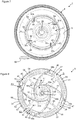
figure 6 illustre une vue d'ensemble d'une turbine constituée du disque avec une partie supérieure en forme de cloche et une partie inférieure présentant un rebord périphérique ; - La
figure 7 illustre en vue de dessus la turbine de lafigure 6 en position dans le réservoir de stockage ; - La
figure 8 illustre la turbine de lafigure 6 en vue de dessous, mettant en évidence les pales incurvées ; - La
figure 9 illustre en vue de dessous le réservoir de stockage avec un organe d'ouverture et de fermeture de l'orifice de transfert en position fermée ; - La
figure 10 illustre en vue de dessous le réservoir de stockage avec un organe d'ouverture et de fermeture de l'orifice de transfert en position ouverte ; - Les
figures 11 et 12 illustrent l'organe d'ouverture et de fermeture de l'orifice de transfert et un levier de commande de cet organe, respectivement en position fermée et en position ouverte.
- The
Figures 1 and 2 illustrate the coffee machine in two positions of an operating member corresponding respectively to the closure of the transfer orifice between the storage tank and the filter holder and, to the opening of the transfer orifice for the transfer of the grinding of the storage tank towards the infusion zone, during the rotation of the disc; - The
figure 3 illustrates the coffee machine in section in order to highlight some of its elements; - The
figure 4 illustrates in section the grinder distributor arranged on the coffee machine; - The
figure 5 illustrates a top view of the storage tank highlighting the transfer orifice in the bottom and the closure of this transfer orifice by an opening and closing member; - The
figure 6 illustrates an overview of a turbine made up of the disc with an upper bell-shaped part and a lower part having a peripheral rim; - The
figure 7 illustrates in top view the turbine of thefigure 6 in position in the storage tank; - The
figure 8 illustrates the turbine of thefigure 6 viewed from below, highlighting the curved blades; - The
figure 9 illustrates a bottom view of the storage tank with an opening and closing member of the transfer orifice in the closed position; - The
figure 10 illustrates a bottom view of the storage tank with an opening and closing member of the transfer orifice in the open position; - The
Figures 11 and 12 illustrate the member for opening and closing the transfer orifice and a control lever for this member, respectively in the closed position and in the open position.
Les
La machine 1 comprend traditionnellement un corps 2 muni d'une base chauffante 3 configurée pour réceptionner une verseuse 4 dans laquelle est déversée la boisson de café (non illustrée). La machine 1 comprend un distributeur de mouture 5 agencé au-dessus d'un porte-filtre 6, le porte-filtre définissant une zone d'infusion 7.The machine 1 traditionally comprises a
Le distributeur de mouture 5 comprend un réservoir de stockage 8 définissant un volume V1 permettant la réception d'une certaine quantité de café moulu, par exemple l'équivalent d'un paquet de 250 grammes de café moulu, que l'on trouve généralement en vente dans le commerce. Ce réservoir de stockage 8 intègre une turbine 9 qui est creuse et qui comprend un disque 10 à sa partie inférieure, ledit disque 10 étant prolongé vers le haut par un corps 11 plus ou moins en forme de cloche. Cette turbine 9 est entraînée en rotation selon un premier axe X1 vertical au moyen d'un moteur 12 agencé selon cet axe X1 à l'intérieur du corps 11, comme l'illustrent les
Tel qu'illustré en
Tel qu'illustré en regard des
Le corps 11 en forme de cloche prolonge le disque 10 sur la partie supérieure de la turbine 9, et forme une seule et même pièce avec celui-ci. Tel qu'illustré notamment en
Tel qu'illustré en regard des
Tel qu'illustré en
Tel qu'illustré en
De préférence, comme illustré en
De même, comme illustré en
L'orifice de transfert 14 sur le fond 13 du réservoir de stockage 8 est positionné en-dessous du disque 10. Les pales 33-36 s'étendent depuis le bord périphérique 30 jusqu'à l'orifice de transfert 14, et au-delà, ce qui permet d'acheminer vers l'intérieur du disque 10 la mouture admise par l'espace périphérique 32, jusqu'à ce que cette mouture atteigne l'orifice de transfert 14, durant la rotation du disque 10.The
Tel que l'illustrent les
Tel que l'illustrent les
Le distributeur de mouture 5 comprend un dispositif de transfert 67 qui permet de dégager l'orifice de transfert 14, dans une position ouverte, et d'obturer ledit orifice de transfert 14, dans une position fermée. En position ouverte, l'acheminement de la mouture de café vers l'orifice de transfert 14 durant la rotation du disque 10 permet son extraction du réservoir de stockage 8 et son transfert vers le porte-filtre 6.The
Ce dispositif de transferts 67, illustré en
L'organe d'ouverture et de fermeture 68 comporte une première partie 68a définissant une ouverture 71 et une paroi inclinée 72 s'étendant en-dessous de cette ouverture 71, comme l'illustrent notamment les
Le système de transmission 70 est un système pignon 74 et crémaillère 75. Le levier de manœuvre 69 est monté à pivotement selon un second axe X2 horizontal, sur le réservoir de stockage 8, comme l'illustrent notamment les
Lorsque le levier de manœuvre 69 est en position verticale vers le haut, comme l'illustre les
Un ressort (non illustré) est monté entre un plot 80 qui s'emboîte sur une première extrémité du ressort et un logement 81 qui réceptionne une seconde extrémité du ressort. Le plot 80 est agencé à l'extrémité arrière 82 de l'organe d'ouverture et de fermeture 68 et le logement 81 est agencé sur un rebord 83 du réservoir de stockage 8, comme l'illustrent les
Tel qu'illustré en
Le réservoir de stockage 8 comprend en-dessous de son fond 13 un organe de nettoyage se présentant sous la forme d'une paroi verticale 85 munie d'un pan incliné 86 disposant d'une pente identique à celle de la paroi inclinée 72, comme l'illustrent les
Tel qu'illustré en
Ces organes de raclage 87-90 sont réalisés dans un matériau souple, notamment un élastomère.These scraping members 87-90 are made of a flexible material, in particular an elastomer.
La description précédente d'un mode préférentiel de conception n'a pas un caractère limitatif. Cette mise en œuvre préférentielle du distributeur de mouture 5 sur la machine 1 permet avantageusement de simplifier sa conception et son coût de fabrication en utilisant un moteur 12 de faible puissance et compact.The foregoing description of a preferred design mode is not limiting. This preferential implementation of the grinding
De nombreuses variantes restent toutefois envisageables, notamment quant à la conception du disque 10. On pourrait notamment prévoir un disque 10 avec un rebord périphérique 30 présentant un diamètre constant et égal au diamètre D du cercle 50, sans aucune décroissance entre deux extrémités distales 33b-36b de pales 33-36, dans quel cas la zone d'admission complémentaire 55-58 n'existerait pas et l'épaisseur de l'espace périphérique 32 entre chaque portion 51-54 sur le disque 10 et le bord périphérique inférieur 31 de la paroi interne 16 du contour 15 serait constante, cette épaisseur correspondant à l'épaisseur minimale E2 comprise entre 0,5 mm et 1 mm, de préférence 0,75 mm.Many variants remain possible, however, in particular as regards the design of the
On pourrait également prévoir des variantes de dispositif de transfert 67, sans sortir du cadre de l'invention.One could also provide variants of
Claims (13)
- Ground coffee dispenser (5) intended to cooperate with a coffee machine (1), which comprises a ground coffee storage reservoir (8) provided with a contour (15) and a bottom (13) and a ground coffee distributor (9) pouring a predefined quantity of ground coffee from the storage reservoir into a brewing area (7) of the coffee machine, the ground coffee distributor (9) comprising a disc (10) driven in rotation on which at least one curved blade (33-36) is attached onto a lower face of said disc (10), the disc (10) having a periphery (30) inscribed in a diameter (D), the bottom (13) of the storage reservoir (8) comprising an opening for transferring (14) the ground coffee arranged under the disc (10) and the curved blade (33-36) extends from the periphery (30) towards the inside of the disc (10) to transfer the ground coffee admitted by a peripheral space (32) into the transfer opening (14) when the disc (10) rotates, characterised in that the quantity of ground coffee poured is defined by the peripheral space (32) arranged between the diameter (D) of the periphery of the disc (10) and an inner wall (16) of the contour (15), close to the bottom (13) of the storage reservoir (8) and in that the disc (10) is extended in the upper portion by a body (11) in the shape of a bell, with the peripheral edge (30) forming a lower portion of said disc.
- Ground coffee dispenser (5) according to claim 1, characterised in that the peripheral space (32) left between the periphery (30) of the disc (10) and the inner wall (16) of the contour (15) has a thickness (E2, E3) comprised between 0.5 and 2 mm, preferably between 0.75 mm and 1.75 mm.
- Ground coffee dispenser (5) according to one of claims 1 or 2, characterised in that the disc (10) comprises between the periphery and the diameter (D) an additional intake zone (55-58) of ground coffee arranged upstream from the curved blade (33-36), in relation to the direction of rotation of the disc (10), the additional intake zone (55-58) having a thickness that increases as the curved blade is approached.
- Ground coffee dispenser (5) according to one of claims 1 to 3, characterised in that the disc (10) comprises a falling peripheral edge (30) disposed facing the inner wall (31), with the peripheral edge (30) comprising at least one opening (38-41) located upstream from the at least one curved blade (33-36), with respect to the direction of rotation of the disc (10).
- Ground coffee dispenser (5) according to one of claims 1 to 4, characterised in that the body (11) comprises at least one first rib (59-62) arranged at the periphery, in line with the curved blade (33-36).
- Ground coffee dispenser (5) according to one of claims 1 to 5, characterised in that the disc (10) comprises a member for scraping (87-90) the bottom (13) of the storage reservoir (8) and for cleaning the transfer opening (14).
- Ground coffee dispenser (5) according to claim 6, characterised in that the member for scraping (87-90) is flexible.
- Ground coffee dispenser (5) according to one of claims 1 to 7, characterised in that the disc (10) is driven in rotation by a motor (12).
- Ground coffee dispenser (5) according to claim 8, characterised in that the disc (10) is driven in rotation along a vertical axis (X1), the motor (12) being arranged at the centre of the disc (10) according to the vertical axis.
- Ground coffee dispenser (5) according to one of claims 1 to 9, characterised in that it comprises a device for transferring (67) that comprises a member for opening and for closing (68) the opening for transferring (14) movable between an open position and a closed position, with the member for opening and for closing (68) being driven by a control lever (69) and a transmission system (70).
- Ground coffee dispenser (5) according to claim 10, characterised in that means for controlling (84) are configured to ensure the starting of a motor (12) for driving the disc (10) when the control lever (69) is actuated.
- Ground coffee dispenser (5) according to one of claims 1 to 11, characterised in that the inner wall (16) comprises at least one second rib (63-66) extending at least over the height thereof close to the peripheral space (32).
- Coffee machine (1) comprising a ground coffee dispenser (5) according to any preceding claim.
Applications Claiming Priority (2)
| Application Number | Priority Date | Filing Date | Title |
|---|---|---|---|
| FR1655051A FR3052044B1 (en) | 2016-06-02 | 2016-06-02 | MILLING DISPENSER FOR COFFEE MACHINE PROVIDED WITH A CURVILINE BLADE TURBINE |
| PCT/FR2017/051350 WO2017207919A1 (en) | 2016-06-02 | 2017-05-30 | Ground coffee dispenser for a coffee machine provided with a turbine with curved blades |
Publications (2)
| Publication Number | Publication Date |
|---|---|
| EP3463006A1 EP3463006A1 (en) | 2019-04-10 |
| EP3463006B1 true EP3463006B1 (en) | 2020-04-15 |
Family
ID=56896706
Family Applications (1)
| Application Number | Title | Priority Date | Filing Date |
|---|---|---|---|
| EP17731237.8A Active EP3463006B1 (en) | 2016-06-02 | 2017-05-30 | Ground coffee dispenser for a coffee machine provided with a turbine with curved blades |
Country Status (5)
| Country | Link |
|---|---|
| US (1) | US11083326B2 (en) |
| EP (1) | EP3463006B1 (en) |
| CN (1) | CN109310232B (en) |
| FR (1) | FR3052044B1 (en) |
| WO (1) | WO2017207919A1 (en) |
Family Cites Families (18)
| Publication number | Priority date | Publication date | Assignee | Title |
|---|---|---|---|---|
| US3305139A (en) * | 1965-04-12 | 1967-02-21 | Wallace W Ward | Powdered material dispenser |
| SE7908778L (en) * | 1979-10-23 | 1981-04-24 | Perete Serverings Syst | DOSING DEVICE AT THE PRINTING AUTOMATIC |
| FR2682271B1 (en) | 1991-10-09 | 1995-08-18 | Moulinex Sa | AUTOMATIC GRINDING DISPENSER AND AUTOMATIC COFFEE MACHINE EQUIPPED WITH SUCH A DISPENSER. |
| DE4408063C1 (en) * | 1994-03-05 | 1995-09-21 | T & P Gmbh | Automatic dispenser for powdery bulk material, especially coffee powder |
| FR2784567B1 (en) * | 1998-10-16 | 2003-04-04 | Moulinex Sa | AUTOMATIC DISPENSER FOR INFUSED BEVERAGES EQUIPPED WITH A GRINDING DISPENSER |
| US6964355B2 (en) * | 2002-06-25 | 2005-11-15 | Gil Gold | Dry food dispensing system |
| BRPI0419066A (en) * | 2004-09-09 | 2008-09-16 | Freeze Solutions Ltda | beverage forming apparatus, refrigeration method and beverage forming and dosing system |
| DE102005053352B4 (en) | 2005-11-07 | 2008-01-10 | Schenck Process Gmbh | Device for metered removal of bulk material |
| US20080148956A1 (en) * | 2006-12-20 | 2008-06-26 | Maurer Scott D | Coffee maker |
| FR2931051B1 (en) * | 2008-05-16 | 2010-04-23 | Seb Sa | AUTOMATIC MOLDED COFFEE DISPENSER |
| FR2924590B1 (en) * | 2007-12-11 | 2009-11-13 | Seb Sa | AUTOMATIC COFFEE MACHINE WITH AUTOMATIC MILLING DISTRIBUTOR |
| AU2010216509B2 (en) * | 2009-02-17 | 2016-10-13 | Koninklijke Douwe Egberts B.V. | Coffee beverage system including coffee bean packaging cartridge |
| US20140072689A1 (en) * | 2011-05-16 | 2014-03-13 | Sunbeam Products, Inc. | Hot Beverage Maker |
| JP2015523103A (en) * | 2012-04-27 | 2015-08-13 | コーニンクレッカ フィリップス エヌ ヴェ | Method and apparatus for grinding coffee beans |
| WO2014121838A1 (en) * | 2013-02-07 | 2014-08-14 | Klaus Kroesen | Apparatus for dispensing a beverage |
| US9750373B2 (en) * | 2014-11-11 | 2017-09-05 | Whirlpool Corporation | High-speed blending blade for a food processing appliance |
| CN204931351U (en) * | 2015-08-06 | 2016-01-06 | 九阳股份有限公司 | A kind of quantitative distributing device of accurate distribution material and food processor thereof |
| CN204931350U (en) * | 2015-08-06 | 2016-01-06 | 九阳股份有限公司 | A kind of milk maker of accurate conveying milk powder |
-
2016
- 2016-06-02 FR FR1655051A patent/FR3052044B1/en not_active Expired - Fee Related
-
2017
- 2017-05-30 CN CN201780034282.9A patent/CN109310232B/en active Active
- 2017-05-30 EP EP17731237.8A patent/EP3463006B1/en active Active
- 2017-05-30 WO PCT/FR2017/051350 patent/WO2017207919A1/en unknown
- 2017-05-30 US US16/305,978 patent/US11083326B2/en active Active
Non-Patent Citations (1)
| Title |
|---|
| None * |
Also Published As
| Publication number | Publication date |
|---|---|
| US20190208951A1 (en) | 2019-07-11 |
| FR3052044A1 (en) | 2017-12-08 |
| CN109310232B (en) | 2020-09-11 |
| FR3052044B1 (en) | 2018-05-18 |
| WO2017207919A1 (en) | 2017-12-07 |
| CN109310232A (en) | 2019-02-05 |
| EP3463006A1 (en) | 2019-04-10 |
| US11083326B2 (en) | 2021-08-10 |
Similar Documents
| Publication | Publication Date | Title |
|---|---|---|
| EP2067421B1 (en) | Automatic dispenser of ground coffee | |
| CA2426840C (en) | Device for improving extraction of a food substance contained in a refill element | |
| BE1019877A5 (en) | COFFEE DRINK SYSTEM, COFFEE BREWING APPARATUS, PACKAGING CARTRIDGE FOR COFFEE BEANS, AND PROCESS FOR PREPARING COFFEE. | |
| CA2435445C (en) | Water injection device for an apparatus for preparing a beverage from a capsule | |
| BE1019953A5 (en) | COFFEE BEAN CARTRIDGE CARTRIDGE MACHINE FOR USE WITH SAID MACHINE, PROCESS FOR PREPARING A BEVERAGE, PROCESS FOR PERCOLATING COFFEE, PROCESS FOR SUPPLYING COFFEE GRAINS, CARTRIDGES FOR COFFEE GRAIN MATERIAL, PROCESS METHOD FOR SUPPLYING A MATERIAL OF COFFEE GRAINS. | |
| EP2293709B1 (en) | Automatic ground-coffee dispenser | |
| WO2007088279A1 (en) | Cooking appliance with stirring means and associated method | |
| FR2902303A1 (en) | PULVERULENT PRODUCT DISPENSER WITH REMOVABLE TANK | |
| FR2886121A1 (en) | Pod ejector device for hot drink e.g. espresso coffee, preparing unit, has pusher with rod projecting outside lower part of tilting receiver plate so that part of rod thrusts against vertical contact surface of unit when plate is tilted | |
| EP3463007B1 (en) | Coffee machine comprising a device for transferring coffee grounds | |
| EP3463006B1 (en) | Ground coffee dispenser for a coffee machine provided with a turbine with curved blades | |
| EP0536714B1 (en) | Automatic distributor for milling products | |
| FR2585829A1 (en) | VOLUMETRIC DOSER FOR POWDER OR GRAIN PRODUCTS, SUCH AS FLOUR, RICE OR COFFEE | |
| FR3083069A1 (en) | ROTARY SHAKING DEVICE OF A BEVERAGE PREPARATION MACHINE EQUIPPED WITH A NON-RETURN VALVE | |
| EP2662000B1 (en) | Ground coffee dispensing device including a pending measuring and dispensing means | |
| EP3708037B1 (en) | Machine for preparing infused beverages provided with an improved filter | |
| EP3937738B1 (en) | Machine for preparing infused beverages provided with a lift-up filter basket | |
| FR2838320A3 (en) | COFFEE PREPARATION DEVICE | |
| WO2002045555A1 (en) | Measuring and dispensing device | |
| FR3074413A1 (en) | MACHINE FOR THE PREPARATION OF BEVERAGE COMPRISING AN INFUSION CHAMBER OF THE OPTIMIZED | |
| EP3708038A1 (en) | Machine for preparing infusions provided with a rotary basket filter | |
| FR2924589A1 (en) | Automatic ground coffee grain dispenser for use in automatic coffee machine to prepare espresso coffee, has driving cone with rotating driving vanes arranged above opening and extended in top portion of reservoir by pyramid-shaped mixer | |
| FR2723524A1 (en) | Automatic machine for producing infusions of hot beverages such as coffee | |
| FR3132290A1 (en) | DOMESTIC COMPACTOR FOR EMPTY PLASTIC CONTAINERS | |
| EP1371953A1 (en) | Distributing-dosing device |
Legal Events
| Date | Code | Title | Description |
|---|---|---|---|
| STAA | Information on the status of an ep patent application or granted ep patent |
Free format text: STATUS: UNKNOWN |
|
| STAA | Information on the status of an ep patent application or granted ep patent |
Free format text: STATUS: THE INTERNATIONAL PUBLICATION HAS BEEN MADE |
|
| PUAI | Public reference made under article 153(3) epc to a published international application that has entered the european phase |
Free format text: ORIGINAL CODE: 0009012 |
|
| STAA | Information on the status of an ep patent application or granted ep patent |
Free format text: STATUS: REQUEST FOR EXAMINATION WAS MADE |
|
| 17P | Request for examination filed |
Effective date: 20181207 |
|
| AK | Designated contracting states |
Kind code of ref document: A1 Designated state(s): AL AT BE BG CH CY CZ DE DK EE ES FI FR GB GR HR HU IE IS IT LI LT LU LV MC MK MT NL NO PL PT RO RS SE SI SK SM TR |
|
| AX | Request for extension of the european patent |
Extension state: BA ME |
|
| DAV | Request for validation of the european patent (deleted) | ||
| DAX | Request for extension of the european patent (deleted) | ||
| GRAP | Despatch of communication of intention to grant a patent |
Free format text: ORIGINAL CODE: EPIDOSNIGR1 |
|
| STAA | Information on the status of an ep patent application or granted ep patent |
Free format text: STATUS: GRANT OF PATENT IS INTENDED |
|
| INTG | Intention to grant announced |
Effective date: 20200206 |
|
| GRAS | Grant fee paid |
Free format text: ORIGINAL CODE: EPIDOSNIGR3 |
|
| GRAA | (expected) grant |
Free format text: ORIGINAL CODE: 0009210 |
|
| STAA | Information on the status of an ep patent application or granted ep patent |
Free format text: STATUS: THE PATENT HAS BEEN GRANTED |
|
| AK | Designated contracting states |
Kind code of ref document: B1 Designated state(s): AL AT BE BG CH CY CZ DE DK EE ES FI FR GB GR HR HU IE IS IT LI LT LU LV MC MK MT NL NO PL PT RO RS SE SI SK SM TR |
|
| REG | Reference to a national code |
Ref country code: CH Ref legal event code: EP |
|
| REG | Reference to a national code |
Ref country code: DE Ref legal event code: R096 Ref document number: 602017014857 Country of ref document: DE |
|
| REG | Reference to a national code |
Ref country code: IE Ref legal event code: FG4D Free format text: LANGUAGE OF EP DOCUMENT: FRENCH |
|
| REG | Reference to a national code |
Ref country code: AT Ref legal event code: REF Ref document number: 1256302 Country of ref document: AT Kind code of ref document: T Effective date: 20200515 |
|
| REG | Reference to a national code |
Ref country code: NL Ref legal event code: MP Effective date: 20200415 |
|
| REG | Reference to a national code |
Ref country code: LT Ref legal event code: MG4D |
|
| PG25 | Lapsed in a contracting state [announced via postgrant information from national office to epo] |
Ref country code: FI Free format text: LAPSE BECAUSE OF FAILURE TO SUBMIT A TRANSLATION OF THE DESCRIPTION OR TO PAY THE FEE WITHIN THE PRESCRIBED TIME-LIMIT Effective date: 20200415 Ref country code: GR Free format text: LAPSE BECAUSE OF FAILURE TO SUBMIT A TRANSLATION OF THE DESCRIPTION OR TO PAY THE FEE WITHIN THE PRESCRIBED TIME-LIMIT Effective date: 20200716 Ref country code: IS Free format text: LAPSE BECAUSE OF FAILURE TO SUBMIT A TRANSLATION OF THE DESCRIPTION OR TO PAY THE FEE WITHIN THE PRESCRIBED TIME-LIMIT Effective date: 20200815 Ref country code: NO Free format text: LAPSE BECAUSE OF FAILURE TO SUBMIT A TRANSLATION OF THE DESCRIPTION OR TO PAY THE FEE WITHIN THE PRESCRIBED TIME-LIMIT Effective date: 20200715 Ref country code: SE Free format text: LAPSE BECAUSE OF FAILURE TO SUBMIT A TRANSLATION OF THE DESCRIPTION OR TO PAY THE FEE WITHIN THE PRESCRIBED TIME-LIMIT Effective date: 20200415 Ref country code: LT Free format text: LAPSE BECAUSE OF FAILURE TO SUBMIT A TRANSLATION OF THE DESCRIPTION OR TO PAY THE FEE WITHIN THE PRESCRIBED TIME-LIMIT Effective date: 20200415 Ref country code: NL Free format text: LAPSE BECAUSE OF FAILURE TO SUBMIT A TRANSLATION OF THE DESCRIPTION OR TO PAY THE FEE WITHIN THE PRESCRIBED TIME-LIMIT Effective date: 20200415 Ref country code: PT Free format text: LAPSE BECAUSE OF FAILURE TO SUBMIT A TRANSLATION OF THE DESCRIPTION OR TO PAY THE FEE WITHIN THE PRESCRIBED TIME-LIMIT Effective date: 20200817 |
|
| REG | Reference to a national code |
Ref country code: AT Ref legal event code: MK05 Ref document number: 1256302 Country of ref document: AT Kind code of ref document: T Effective date: 20200415 |
|
| PG25 | Lapsed in a contracting state [announced via postgrant information from national office to epo] |
Ref country code: BG Free format text: LAPSE BECAUSE OF FAILURE TO SUBMIT A TRANSLATION OF THE DESCRIPTION OR TO PAY THE FEE WITHIN THE PRESCRIBED TIME-LIMIT Effective date: 20200715 Ref country code: HR Free format text: LAPSE BECAUSE OF FAILURE TO SUBMIT A TRANSLATION OF THE DESCRIPTION OR TO PAY THE FEE WITHIN THE PRESCRIBED TIME-LIMIT Effective date: 20200415 Ref country code: RS Free format text: LAPSE BECAUSE OF FAILURE TO SUBMIT A TRANSLATION OF THE DESCRIPTION OR TO PAY THE FEE WITHIN THE PRESCRIBED TIME-LIMIT Effective date: 20200415 Ref country code: LV Free format text: LAPSE BECAUSE OF FAILURE TO SUBMIT A TRANSLATION OF THE DESCRIPTION OR TO PAY THE FEE WITHIN THE PRESCRIBED TIME-LIMIT Effective date: 20200415 |
|
| PG25 | Lapsed in a contracting state [announced via postgrant information from national office to epo] |
Ref country code: AL Free format text: LAPSE BECAUSE OF FAILURE TO SUBMIT A TRANSLATION OF THE DESCRIPTION OR TO PAY THE FEE WITHIN THE PRESCRIBED TIME-LIMIT Effective date: 20200415 |
|
| REG | Reference to a national code |
Ref country code: DE Ref legal event code: R097 Ref document number: 602017014857 Country of ref document: DE |
|
| PG25 | Lapsed in a contracting state [announced via postgrant information from national office to epo] |
Ref country code: ES Free format text: LAPSE BECAUSE OF FAILURE TO SUBMIT A TRANSLATION OF THE DESCRIPTION OR TO PAY THE FEE WITHIN THE PRESCRIBED TIME-LIMIT Effective date: 20200415 Ref country code: MC Free format text: LAPSE BECAUSE OF FAILURE TO SUBMIT A TRANSLATION OF THE DESCRIPTION OR TO PAY THE FEE WITHIN THE PRESCRIBED TIME-LIMIT Effective date: 20200415 Ref country code: AT Free format text: LAPSE BECAUSE OF FAILURE TO SUBMIT A TRANSLATION OF THE DESCRIPTION OR TO PAY THE FEE WITHIN THE PRESCRIBED TIME-LIMIT Effective date: 20200415 Ref country code: DK Free format text: LAPSE BECAUSE OF FAILURE TO SUBMIT A TRANSLATION OF THE DESCRIPTION OR TO PAY THE FEE WITHIN THE PRESCRIBED TIME-LIMIT Effective date: 20200415 Ref country code: SM Free format text: LAPSE BECAUSE OF FAILURE TO SUBMIT A TRANSLATION OF THE DESCRIPTION OR TO PAY THE FEE WITHIN THE PRESCRIBED TIME-LIMIT Effective date: 20200415 Ref country code: IT Free format text: LAPSE BECAUSE OF FAILURE TO SUBMIT A TRANSLATION OF THE DESCRIPTION OR TO PAY THE FEE WITHIN THE PRESCRIBED TIME-LIMIT Effective date: 20200415 Ref country code: EE Free format text: LAPSE BECAUSE OF FAILURE TO SUBMIT A TRANSLATION OF THE DESCRIPTION OR TO PAY THE FEE WITHIN THE PRESCRIBED TIME-LIMIT Effective date: 20200415 Ref country code: RO Free format text: LAPSE BECAUSE OF FAILURE TO SUBMIT A TRANSLATION OF THE DESCRIPTION OR TO PAY THE FEE WITHIN THE PRESCRIBED TIME-LIMIT Effective date: 20200415 Ref country code: LI Free format text: LAPSE BECAUSE OF NON-PAYMENT OF DUE FEES Effective date: 20200531 Ref country code: CH Free format text: LAPSE BECAUSE OF NON-PAYMENT OF DUE FEES Effective date: 20200531 Ref country code: CZ Free format text: LAPSE BECAUSE OF FAILURE TO SUBMIT A TRANSLATION OF THE DESCRIPTION OR TO PAY THE FEE WITHIN THE PRESCRIBED TIME-LIMIT Effective date: 20200415 |
|
| PLBE | No opposition filed within time limit |
Free format text: ORIGINAL CODE: 0009261 |
|
| STAA | Information on the status of an ep patent application or granted ep patent |
Free format text: STATUS: NO OPPOSITION FILED WITHIN TIME LIMIT |
|
| PG25 | Lapsed in a contracting state [announced via postgrant information from national office to epo] |
Ref country code: PL Free format text: LAPSE BECAUSE OF FAILURE TO SUBMIT A TRANSLATION OF THE DESCRIPTION OR TO PAY THE FEE WITHIN THE PRESCRIBED TIME-LIMIT Effective date: 20200415 Ref country code: SK Free format text: LAPSE BECAUSE OF FAILURE TO SUBMIT A TRANSLATION OF THE DESCRIPTION OR TO PAY THE FEE WITHIN THE PRESCRIBED TIME-LIMIT Effective date: 20200415 |
|
| REG | Reference to a national code |
Ref country code: BE Ref legal event code: MM Effective date: 20200531 |
|
| 26N | No opposition filed |
Effective date: 20210118 |
|
| PG25 | Lapsed in a contracting state [announced via postgrant information from national office to epo] |
Ref country code: LU Free format text: LAPSE BECAUSE OF NON-PAYMENT OF DUE FEES Effective date: 20200530 |
|
| PG25 | Lapsed in a contracting state [announced via postgrant information from national office to epo] |
Ref country code: IE Free format text: LAPSE BECAUSE OF NON-PAYMENT OF DUE FEES Effective date: 20200530 |
|
| PG25 | Lapsed in a contracting state [announced via postgrant information from national office to epo] |
Ref country code: SI Free format text: LAPSE BECAUSE OF FAILURE TO SUBMIT A TRANSLATION OF THE DESCRIPTION OR TO PAY THE FEE WITHIN THE PRESCRIBED TIME-LIMIT Effective date: 20200415 Ref country code: BE Free format text: LAPSE BECAUSE OF NON-PAYMENT OF DUE FEES Effective date: 20200531 |
|
| GBPC | Gb: european patent ceased through non-payment of renewal fee |
Effective date: 20210530 |
|
| PG25 | Lapsed in a contracting state [announced via postgrant information from national office to epo] |
Ref country code: GB Free format text: LAPSE BECAUSE OF NON-PAYMENT OF DUE FEES Effective date: 20210530 |
|
| PG25 | Lapsed in a contracting state [announced via postgrant information from national office to epo] |
Ref country code: TR Free format text: LAPSE BECAUSE OF FAILURE TO SUBMIT A TRANSLATION OF THE DESCRIPTION OR TO PAY THE FEE WITHIN THE PRESCRIBED TIME-LIMIT Effective date: 20200415 Ref country code: MT Free format text: LAPSE BECAUSE OF FAILURE TO SUBMIT A TRANSLATION OF THE DESCRIPTION OR TO PAY THE FEE WITHIN THE PRESCRIBED TIME-LIMIT Effective date: 20200415 Ref country code: CY Free format text: LAPSE BECAUSE OF FAILURE TO SUBMIT A TRANSLATION OF THE DESCRIPTION OR TO PAY THE FEE WITHIN THE PRESCRIBED TIME-LIMIT Effective date: 20200415 |
|
| PG25 | Lapsed in a contracting state [announced via postgrant information from national office to epo] |
Ref country code: MK Free format text: LAPSE BECAUSE OF FAILURE TO SUBMIT A TRANSLATION OF THE DESCRIPTION OR TO PAY THE FEE WITHIN THE PRESCRIBED TIME-LIMIT Effective date: 20200415 |
|
| PGFP | Annual fee paid to national office [announced via postgrant information from national office to epo] |
Ref country code: FR Payment date: 20230523 Year of fee payment: 7 Ref country code: DE Payment date: 20230510 Year of fee payment: 7 |