EP3462855B1 - Regulating and/or control system, agricultural machine comprising such a system, and method for operating an agricultural machine - Google Patents
Regulating and/or control system, agricultural machine comprising such a system, and method for operating an agricultural machine Download PDFInfo
- Publication number
- EP3462855B1 EP3462855B1 EP17720807.1A EP17720807A EP3462855B1 EP 3462855 B1 EP3462855 B1 EP 3462855B1 EP 17720807 A EP17720807 A EP 17720807A EP 3462855 B1 EP3462855 B1 EP 3462855B1
- Authority
- EP
- European Patent Office
- Prior art keywords
- distributor linkage
- sensor device
- sensor
- inclination
- machine
- Prior art date
- Legal status (The legal status is an assumption and is not a legal conclusion. Google has not performed a legal analysis and makes no representation as to the accuracy of the status listed.)
- Active
Links
- 238000000034 method Methods 0.000 title claims description 10
- 230000001105 regulatory effect Effects 0.000 title claims 3
- 230000001133 acceleration Effects 0.000 claims description 35
- 238000012545 processing Methods 0.000 claims description 27
- 238000005259 measurement Methods 0.000 claims description 22
- 230000005484 gravity Effects 0.000 claims description 21
- 238000012937 correction Methods 0.000 claims description 16
- 239000000463 material Substances 0.000 claims description 9
- 239000003337 fertilizer Substances 0.000 claims description 7
- 239000004476 plant protection product Substances 0.000 claims description 5
- 230000007480 spreading Effects 0.000 claims description 5
- 238000003892 spreading Methods 0.000 claims description 5
- 230000005540 biological transmission Effects 0.000 claims description 4
- 230000008569 process Effects 0.000 claims description 4
- 238000003860 storage Methods 0.000 claims description 3
- 230000008901 benefit Effects 0.000 description 5
- 238000004364 calculation method Methods 0.000 description 2
- 239000003990 capacitor Substances 0.000 description 2
- 230000008859 change Effects 0.000 description 2
- 238000009826 distribution Methods 0.000 description 2
- 239000011814 protection agent Substances 0.000 description 2
- 239000002689 soil Substances 0.000 description 2
- 238000013461 design Methods 0.000 description 1
- 238000001514 detection method Methods 0.000 description 1
- 238000010586 diagram Methods 0.000 description 1
- 230000000694 effects Effects 0.000 description 1
- -1 fertilisers Substances 0.000 description 1
- 230000001771 impaired effect Effects 0.000 description 1
- 238000012423 maintenance Methods 0.000 description 1
- 230000007246 mechanism Effects 0.000 description 1
- 238000005096 rolling process Methods 0.000 description 1
- 239000000725 suspension Substances 0.000 description 1
- 230000001960 triggered effect Effects 0.000 description 1
Images


Classifications
-
- A—HUMAN NECESSITIES
- A01—AGRICULTURE; FORESTRY; ANIMAL HUSBANDRY; HUNTING; TRAPPING; FISHING
- A01M—CATCHING, TRAPPING OR SCARING OF ANIMALS; APPARATUS FOR THE DESTRUCTION OF NOXIOUS ANIMALS OR NOXIOUS PLANTS
- A01M7/00—Special adaptations or arrangements of liquid-spraying apparatus for purposes covered by this subclass
- A01M7/005—Special arrangements or adaptations of the spraying or distributing parts, e.g. adaptations or mounting of the spray booms, mounting of the nozzles, protection shields
- A01M7/0053—Mounting of the spraybooms
- A01M7/0057—Mounting of the spraybooms with active regulation of the boom position
Definitions
- the invention relates to a regulation and/or control system for an agricultural machine with a distributor linkage for spreading material such as fertilisers, plant protection products or seeds.
- the distributor linkage can be pivoted about at least one axis of rotation running in the direction of travel.
- the regulation and/or control system has at least one first sensor device for determining the inclination of the distributor linkage and a data processing device for processing the sensor signals from the first sensor device.
- Such a system is, for example, from WO 2015 040 133 A1 known.
- the disadvantage of the known system is that the inclination sensors supply faulty signals when cornering. proposes to the solution WO 2015 040 133 A1 proposes to measure the rate of rotation around the axis of rotation running in the direction of travel in addition to the inclination of the linkage. The angle of inclination of the linkage is calculated from the measured rate of rotation and, together with the measured angle of inclination, an error-corrected rotational position of the linkage is determined. Only rolling movements of the carrier vehicle around the axis of rotation of the linkage running in the direction of travel are recorded.
- the object of the invention is to improve the regulation and/or control system of the type mentioned at the outset with a view to measuring accuracy in different driving situations.
- the invention is also based on the object of specifying an agricultural machine with such a system and a method for operating an agricultural machine.
- the object is achieved according to the invention by the subject matter of claim 1 .
- the object is achieved according to the invention by the subject matter of claim 10 or the subject matter of claim 12.
- the invention is based on the idea of specifying a regulation and/or control system for an agricultural machine that has a distributor linkage for spreading material such as fertilizers, crop protection agents or seed.
- the distributor linkage can be pivoted about at least one axis of rotation running in the direction of travel.
- the system has at least a first sensor device for determining the inclination of the distributor linkage and a data processing device for processing the sensor signals.
- the invention is characterized by a second sensor device for determining the centrifugal force F F and/or the centrifugal acceleration a F which acts on the first sensor device when the machine is cornering.
- the data processing device is designed in such a way that an inclination measurement error of the first sensor device can be corrected on the basis of the sensor signals of the second sensor device.
- the invention has the advantage that the disturbance variable which falsifies the measurement result, namely the centrifugal force F F and/or the centrifugal acceleration a F , is determined directly at the first sensor device. Especially when cornering, this means that measurement errors are eliminated and the measurement accuracy is significantly improved.
- the centrifugal force F F and/or the centrifugal acceleration a F can be determined in various ways.
- the centrifugal force F F is preferably determined directly by measurement by the second sensor device.
- the centrifugal force F F and/or the centrifugal acceleration a F can, for example, also be calculated indirectly on the basis of vehicle parameters, such as the yaw rate about the vertical axis and the driving speed, with the yaw rate preferably being measured by the second sensor device.
- the data processing device is adapted to process the driving speed of the machine.
- the vehicle speed is corrected based on the sensor signals during error correction the second sensor device is taken into account.
- the driving speed is included in the calculation of the centrifugal acceleration.
- the data processing device can be adapted to factor the driving speed, with the factoring being adjustable. This allows possible constant errors in the calculation to be compensated.
- the data processing device can be adapted to process a steering angle of the machine, which is taken into account in the error correction based on the sensor signals of the second sensor device
- the second sensor device can include at least one yaw rate sensor, which is adapted to measure the yaw rate of the distributor linkage and/or the machine about the vertical axis. Based on the measurement of the yaw rate about the vertical axis, the load on the first sensor device can be determined by transverse forces, for example when cornering.
- the vertical axis or vertical axis is the axis about which yaw movements of the distributor linkage and/or the machine take place, the angular velocity of which is measured by the yaw rate sensor.
- Another advantage of detecting the yaw rate about the vertical axis is that the error correction is very precise when cornering continues. In contrast to this, inaccuracies can occur during continuous cornering due to drift effects in the correction by means of the known detection of the rate of rotation about the axis of rotation running in the direction of travel.
- the second sensor device can comprise a plurality of yaw rate sensors, in particular at least two or three yaw rate sensors, whose measuring axes run orthogonally to one another. This improves the measurement in the event that the second sensor device itself is inclined.
- the directions of rotation can be better determined in this way, specifically by determining a resulting rate of rotation based on the measurements about the axes of rotation that are orthogonal to one another.
- the first sensor device can be based on an inclination sensor, in particular an inclination sensor for measuring the inclination of the distributor linkage a reference axis running in the direction of gravitational acceleration (direction of perpendicular).
- This has the advantage that it is possible to regulate to an absolute inclination value in relation to the direction of gravity, ie in the direction of the force of gravity (weight) acting downwards.
- the first sensor device comprises a sensor for determining the rate of rotation of the distributor linkage about the axis of rotation of the distributor linkage running in the direction of travel.
- the sensor for determining the yaw rate can be a yaw rate sensor or an acceleration sensor.
- the sensor for determining the rate of rotation of the distributor linkage can be combined with the inclination sensor. This has the advantage that the target value for the inclination can be specified by the user.
- the machine movements are decoupled from the linkage movements on the basis of the signals from the sensor for determining the rate of rotation of the distributor linkage.
- the data processing device is adapted accordingly.
- At least one third sensor device is provided for determining the distance of the distributor linkage from the ground and/or from the vegetation and/or from obstacles. With the aid of the third sensor device, the inclination of the distributor linkage is set in relation to the ground.
- the data processing device is preferably configured for an automatic mode for adjusting the height and/or inclination of the distributor linkage and for an override mode for adjusting the height and/or inclination of the distributor linkage.
- the override mode can be a manual override mode, for example.
- automatic mode the data processing device adjusts the overall height and/or overall inclination of the distributor linkage.
- the data processing device overrides at least one control parameter of the automatic mode that is active in the override mode.
- the data processing device overrides at least one control parameter of the automatic mode, in particular through a manual input.
- Override means that the automatic mode is active in the override mode or remains active when the automatic mode override mode is switched on.
- a control parameter of the automatic mode e.g. the absolute inclination value in relation to the direction of gravity, is specifically changed in the override mode in order to give the user of the machine the opportunity to intervene in the automatic control, e.g. to avoid collisions.
- the override is preferably a manual override, ie an override that is at least triggered by a manual input by a user.
- Manual override may also include user adjustment of control behavior.
- the automatic mode is the regulation during normal operation of the machine.
- the override when the automatic mode is active ensures that the active decoupling of the movements of the distributor linkage from the movements of the machine, e.g. due to the sensor for determining the rate of rotation of the distributor linkage around the axis of rotation of the distributor linkage running in the direction of travel, is maintained, even if a Intervention, in particular manual intervention, takes place in the automatic control.
- a Intervention in particular manual intervention
- the data processing device is preferably configured for a manual mode with rigid power transmission to the distributor linkage, with a change to a decoupling mode with a decoupled distributor linkage, in particular in the automatic mode and/or in the override mode, a current inclination value of the distributor linkage being adopted as the new desired inclination value.
- the second sensor device for determining the centrifugal force F F and / or the centrifugal acceleration a F which acts on the first Sensor device acts when cornering the machine, is arranged on the machine or on the distributor linkage.
- the method according to the invention for operating an agricultural machine is based on the fact that material, such as fertilizer, crop protection agent or seed, is applied from a storage container through a distributor linkage.
- material such as fertilizer, crop protection agent or seed
- an absolute inclination value of the distributor linkage relative to the direction of gravity is controlled on the basis of sensor signals from at least one first sensor device for determining the inclination of the distributor linkage.
- a measurement error of the first sensor device is corrected on the basis of sensor signals from at least one second sensor device for determining the centrifugal force F F and/or the centrifugal acceleration a F that acts on the first sensor device when the machine is cornering. This improves the measurement accuracy.
- FIG. 1 shows a schematic rear view of an agricultural machine 2, which is designed as a field sprayer.
- the machine can be towed, self-propelled or vehicle-mounted.
- the machine has a distributor linkage 3, which is connected to a storage container 5 for the supply of the material to be spread.
- the material can be crop protection products, seeds or fertilizers.
- the distributor linkage 3 has nozzles which are distributed on the underside of the distributor linkage 3 .
- the nozzles are connected to a pump and the reservoir 5 by a hose system, which is also known per se.
- the distributor linkage 3 is suspended centrally on the frame of the machine and can be pivoted about an axis of rotation pointing in the direction of travel, as indicated by the double arrow. An adjustment of the overall inclination of the distributor linkage 3, ie an adjustment of the unfolded, straight distributor linkage 3, is thus possible.
- the axis of rotation a is at a distance from the center of gravity b of the distributor linkage 3 .
- the centrifugal forces also act on those for tilt control provided inclination sensors or the inclination sensor.
- the regulation and/or control system is adapted accordingly, as described in more detail below.
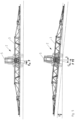
- the invention and the exemplary embodiments described below relate to a distributor linkage according to FIG 2 with the center of gravity b of the distributor linkage 3 spaced axis of rotation a. It is also conceivable to apply the invention or the exemplary embodiments described below to a distributor linkage 3 in which the axis of rotation a, about which the distributor linkage 3 can be pivoted, runs through the center of gravity b.
- the distributor linkage 3 can have a non-rotatably arranged central part, on which a respective cantilever arm is articulated in a pivotable manner.
- a respective cantilever arm is articulated in a pivotable manner.
- the two pivot arms can each be pivoted about a central axis of the vehicle pointing in the direction of travel.
- the distributor linkage 3 is also adjustable in height.
- the distributor linkage can be attached to a vertically movable lifting frame.
- a parallelogram linkage can be provided to adjust the altitude.
- Hydraulic systems known per se or other adjustment systems can be considered as actuators for the inclination and height adjustment.
- the invention is not limited to a specific mechanism for adjusting the inclination or for adjusting the height of the distributor linkage 3 .
- the agricultural machine 2 has a regulation and/or control system (not shown), which includes a data processing device for processing sensor signals from various sensor devices, which are explained in more detail below.
- the regulation and/or control system has a first sensor device, which is designed to determine the inclination of the distributor linkage 3 .
- the first sensor device includes an inclination sensor for detecting the inclination of the distributor linkage 3 in relation to the direction of gravity.
- the tilt sensor is based on the principle of measuring the inclination of the distributor linkage 3 in relation to the vertical direction predetermined by gravity or the direction of gravitational acceleration. This can be done in a manner known per se using a pendulum that is mounted mechanically or electromagnetically and whose position is measured electronically, inductively, capacitively or optically.
- An example of such a pendulum is a system of two parallel plate capacitors sharing a common middle plate.
- the center plate of the differential capacitor shifts due to gravitational acceleration, changing the capacitance ratio. This change is evaluated and a corresponding output signal is generated.
- the deflection relative to the direction of gravitational acceleration is determined by a spring-mass system.
- the first sensor device can include a further sensor for determining the rate of rotation of the distributor linkage about the axis of rotation a of the distributor linkage running in the direction of travel.
- This can be a yaw rate sensor or an acceleration sensor.
- a single yaw rate sensor can suffice, which measures the angular velocity during a rotational movement of the distributor linkage 3 about the centrally running axis of rotation a.
- each cantilever arm is expediently assigned its own yaw rate sensor.
- the system has a second sensor device which is adapted to detect a rate of rotation, i.e. angular velocity around the vertical axis of the distributor linkage or around the vertical axis of the associated vehicle.
- the vertical axis also known as the yaw axis or vertical axis, is the vertical axis of the vehicle's fixed coordinate system.
- the second sensor device can have one or more yaw rate sensors or acceleration sensors.
- two or three yaw rate sensors can be provided which are orthogonally attached to one another and are combined to form an inertial measurement system.
- a third sensor device which measures the distance between the distributor linkage 3 and the ground or the surface of the crop. doing so
- These are ultrasonic sensors that are mounted on the distributor linkage 3, in particular on the in 1 shown outer positions on the distributor linkage 3 are arranged. Other sensors for distance measurement are possible.
- two distance sensors 4 are provided for measuring the left and right height h l , h r of the distributor linkage 3 in relation to the ground.
- the first and second sensor device can be arranged at different positions on the distributor linkage and/or on the carrier vehicle or towing vehicle.
- the regulation and/or control system works as follows:
- the data processing device enables different operating modes.
- the system can thus switch between an automatic mode, an override mode and a manual mode.
- the distributor linkage 3 is aligned parallel to the ground or to the surface of the crop by the third sensor device, ie by the distance sensors 4 on the distributor linkage 3 .
- the control circuits required for this are known per se.
- the boom movements are actively decoupled from the machine movements.
- the first sensor device specifically the yaw rate sensor, which measures the angular velocity about the axis of rotation a of the distributor linkage 3 running in the direction of travel, is responsible for this.
- the target value of this angular velocity is set to 0 in automatic mode.
- the actuators responsible for the inclination specifically the inclination cylinders, move continuously with the machine movements, as a result of which a transmission of forces and moments resulting from the machine movements to the distributor linkage 3 is avoided.
- the tilt cylinders follow the relative movements between the distributor linkage 3 and the machine 2.
- the distributor linkage 3 and the machine 2 are thus not rigidly connected by the tilt cylinders.
- the user has the option of changing a control parameter in such a way that the position, specifically the tilted position, of the distributor linkage 3 is changed without the active decoupling being impaired or even terminated.
- the maintenance of active decoupling in override mode, as in automatic mode, is achieved by the target value for the rate of rotation of the distributor linkage 3 about the axis of rotation running in the direction of travel is set to zero.
- the tilt cylinders move continuously and prevent the transmission of forces or moments from the machine 2 to the distributor linkage 3.
- the control intervention in the override mode takes place on the basis of user inputs or a user input which relates to the absolute angle of inclination of the distributor linkage in relation to the direction of gravity.
- the reference gravity direction replaces the ground or crop surface as the reference. In this way, the incline is controlled to an absolute incline value relative to the direction of gravity.
- the inclination control based on the first sensor device takes place independently of the distance control to the ground or vegetation.
- the target value for the inclination is specified by the respective user.
- the inclination control regulates around the specified target value and at the same time actively decouples the boom from the machine movements.
- This target angle of inclination can therefore be set manually, so that the angle of inclination of the distributor linkage 3 is changed by controlling the inclination cylinder in accordance with the user inputs.
- the active decoupling based on the rotation rate of the distributor linkage 3 is continued at the same time.
- the distributor linkage In manual mode, the distributor linkage is rigidly connected to the machine.
- the tilt cylinders transmit forces and moments due to machine movement to the distributor linkage 3. Active decoupling is terminated in manual mode.
- the tilting cylinders can be moved to the left or right in a defined manner via the regulation and/or control system in order to rotate the distributor linkage 3 accordingly.
- the distributor linkage 3 shows the distributor linkage 3 when driving straight ahead. No lateral forces act on the inclination sensor.
- the distributor linkage 3 is in the parallel position on the one hand to the ground and on the other hand to a plane perpendicular to the direction of gravity.
- the measured and actual angle between the vertical axis and in the direction of gravitational acceleration (direction of gravity) is 0°.
- the machine 2 is tilted sideways together with the distributor linkage 3, for example by driving on one side in a furrow.
- the reference plane perpendicular to the direction of gravity does not correspond to the soil surface shown schematically, but deviates from the soil surface by the angle beta. The same applies to the normal to the reference plane, which deviates from the direction of gravity by the angle beta.
- the inclination sensor detects the alignment of the distributor linkage 3 in relation to the direction of gravitational acceleration (direction of gravity) perpendicular to the ground, as can be seen in the illustration below.
- gravitational acceleration direction of gravity
- the rate of rotation of the machine 2 about the vertical axis and the driving speed of the machine are recorded and taken into account in the error correction.
- FIG 5 the driving condition is shown during a right turn.
- lateral accelerations or centrifugal forces occur depending on the curve radius and the driving speed, which lead to a deviation of the measured angle from the actual angle.
- FIG. 6 shows the acceleration diagram in the case of a left turn (see 4 ), from which the transverse acceleration and thus the centrifugal force can be seen, which acts on the inclination sensor and leads to a measurement error which is corrected by the invention or the exemplary embodiment according to the invention.
- the linkage is aligned horizontally to the reference plane normal to the direction of gravity and to the natural horizon. Without correction, an incorrect angle alpha to the horizon would be recorded by the inclination sensor (see also 4 , upper representation).
- the error correction takes place in a simplified manner on the basis of the yaw rate about the vertical axis, which is measured by the second sensor device, and the driving speed, which is detected in a manner known per se.
- a correction term is thereby determined which corrects the deviation of the measurement acceleration a M from the gravitational acceleration a G .
- a corresponding correction algorithm is stored in the data processing device.
- the inventions or the above-mentioned exemplary embodiments are not restricted to the algorithm reproduced below, which is to be understood as a possible example of how the measurement error occurring as a result of the transverse forces can be corrected, taking into account the rate of rotation about the vertical axis and the driving speed of the machine.
Description
Die Erfindung betrifft ein Regel-und/oder Steuersystem für eine landwirtschaftliche Maschine mit einem Verteilergestänge zum Ausbringen von Material, wie Düngemittel, Pflanzenschutzmittel oder Saatgut. Das Verteilergestänge ist um mindestens eine in Fahrtrichtung verlaufende Drehachse verschwenkbar. Das Regel-und/oder Steuersystem weist wenigstens eine erste Sensoreinrichtung zur Ermittlung der Neigung des Verteilergestänges sowie eine Datenverarbeitungseinrichtung zur Verarbeitung der Sensorsignale der ersten Sensoreinrichtung auf.The invention relates to a regulation and/or control system for an agricultural machine with a distributor linkage for spreading material such as fertilisers, plant protection products or seeds. The distributor linkage can be pivoted about at least one axis of rotation running in the direction of travel. The regulation and/or control system has at least one first sensor device for determining the inclination of the distributor linkage and a data processing device for processing the sensor signals from the first sensor device.
Ein solches System ist beispielsweise aus
Als nachteilig wird an dem bekannten System beschrieben, dass die Neigungssensoren bei Kurvenfahrten fehlerhafte Signale liefern. Zur Lösung schlägt
Der Erfindung liegt die Aufgabe zu Grunde, das Regel- und/oder Steuersystem der eingangs genannten Art mit Blick auf die Messgenauigkeit in unterschiedlichen Fahrsituationen zu verbessern. Der Erfindung liegt ferner die Aufgabe zu Grunde, eine landwirtschaftliche Maschine mit einem solchen System sowie ein Verfahren zum Betreiben einer landwirtschaftlichen Maschine anzugeben.The object of the invention is to improve the regulation and/or control system of the type mentioned at the outset with a view to measuring accuracy in different driving situations. The invention is also based on the object of specifying an agricultural machine with such a system and a method for operating an agricultural machine.
Die Aufgabe wird hinsichtlich des Regel- und/oder Steuersystems für eine landwirtschaftliche Maschine erfindungsgemäß durch den Gegenstand des Anspruchs 1 gelöst. Mit Blick auf die landwirtschaftliche Maschine und das Verfahren zum Betreiben einer landwirtschaftlichen Maschine wird die Aufgabe erfindungsgemäß durch den Gegenstand des Anspruchs 10 bzw. den Gegenstand des Anspruchs 12 gelöst.With regard to the regulation and/or control system for an agricultural machine, the object is achieved according to the invention by the subject matter of claim 1 . Looking at the agricultural machine and that Method for operating an agricultural machine, the object is achieved according to the invention by the subject matter of claim 10 or the subject matter of claim 12.
Danach beruht die Erfindung auf den Gedanken, ein Regel- und/oder Steuersystem für eine landwirtschaftliche Maschine anzugeben, das ein Verteilergestänge zum Ausbringen von Material, wie Düngemittel, Pflanzenschutzmittel oder Saatgut aufweist. Das Verteilergestänge ist um wenigstens eine in Fahrtrichtung verlaufende Drehachse verschwenkbar. Das System weist wenigstens eine erste Sensoreinrichtung zur Ermittlung der Neigung des Verteilergestänges und eine Datenverarbeitungseinrichtung zur Verarbeitung der Sensorsignale auf. Die Erfindung zeichnet sich durch eine zweite Sensoreinrichtung zur Ermittlung der Zentrifugalkraft FF und/oder der Zentrifugalbeschleunigung aF, die auf die erste Sensoreinrichtung bei Kurvenfahrten der Maschine wirkt, aus. Die Datenverarbeitungseinrichtung ist derart ausgebildet, dass ein Neigungsmessfehler der ersten Sensoreinrichtung auf der Basis der Sensorsignale der zweiten Sensoreinrichtung korrigierbar ist.According to this, the invention is based on the idea of specifying a regulation and/or control system for an agricultural machine that has a distributor linkage for spreading material such as fertilizers, crop protection agents or seed. The distributor linkage can be pivoted about at least one axis of rotation running in the direction of travel. The system has at least a first sensor device for determining the inclination of the distributor linkage and a data processing device for processing the sensor signals. The invention is characterized by a second sensor device for determining the centrifugal force F F and/or the centrifugal acceleration a F which acts on the first sensor device when the machine is cornering. The data processing device is designed in such a way that an inclination measurement error of the first sensor device can be corrected on the basis of the sensor signals of the second sensor device.
Die Erfindung hat den Vorteil, dass direkt an der ersten Sensoreinrichtung die Störgröße ermittelt wird, die das Messergebnis verfälscht, nämlich die Zentrifugalkraft FF und/oder die Zentrifugalbeschleunigung aF. Gerade bei Kurvenfahrten führt dies dazu, dass Messfehler eliminiert werden und die Messgenauigkeit signifikant verbessert wird.The invention has the advantage that the disturbance variable which falsifies the measurement result, namely the centrifugal force F F and/or the centrifugal acceleration a F , is determined directly at the first sensor device. Especially when cornering, this means that measurement errors are eliminated and the measurement accuracy is significantly improved.
Die Ermittlung der Zentrifugalkraft FF und/oder der Zentrifugalbeschleunigung aF kann auf verschiedene Weise erfolgen. Vorzugsweise erfolgt die Ermittlung der Zentrifugalkraft FF direkt durch Messung durch die zweite Sensoreinrichtung. Die Zentrifugalkraft FF und/oder der Zentrifugalbeschleunigung aF kann bspw. auch indirekt durch Berechnung auf der Basis von Fahrzeugparametern, wie bspw. der Drehrate um die Hochachse und der Fahrgeschwindigkeit erfolgen, wobei die Drehrate vorzugsweise durch die zweite Sensoreinrichtung gemessen wird.The centrifugal force F F and/or the centrifugal acceleration a F can be determined in various ways. The centrifugal force F F is preferably determined directly by measurement by the second sensor device. The centrifugal force F F and/or the centrifugal acceleration a F can, for example, also be calculated indirectly on the basis of vehicle parameters, such as the yaw rate about the vertical axis and the driving speed, with the yaw rate preferably being measured by the second sensor device.
Bevorzugte Ausführungen der Erfindung sind in den Unteransprüchen angegeben.Preferred embodiments of the invention are specified in the subclaims.
Bei einer bevorzugten Ausführungsform ist die Datenverarbeitungseinrichtung zur Verarbeitung der Fahrgeschwindigkeit der Maschine angepasst. Die Fahrgeschwindigkeit wird bei der Fehlerkorrektur auf der Basis der Sensorsignale der zweiten Sensoreinrichtung berücksichtigt. Konkret geht die Fahrgeschwindigkeit in die Berechnung der Zentrifugalbeschleunigung ein.In a preferred embodiment, the data processing device is adapted to process the driving speed of the machine. The vehicle speed is corrected based on the sensor signals during error correction the second sensor device is taken into account. Specifically, the driving speed is included in the calculation of the centrifugal acceleration.
Dabei kann die Datenverarbeitungseinrichtung zur Faktorisierung der Fahrgeschwindigkeit angepasst sein, wobei die Faktorisierung verstellbar ist. Dadurch können mögliche konstante Fehler in der Berechnung kompensiert werden.The data processing device can be adapted to factor the driving speed, with the factoring being adjustable. This allows possible constant errors in the calculation to be compensated.
Die Datenverarbeitungseinrichtung kann zur Verarbeitung eines Lenkwinkels der Maschine angepasst sein, der bei der Fehlerkorrektur auf der Basis der Sensorsignale der zweiten Sensoreinrichtung berücksichtigt wird
Die zweite Sensoreinrichtung kann wenigstens einen Drehratensensor umfassen, der zur Messung der Drehrate des Verteilergestänges und/oder der Maschine um die Hochachse angepasst ist. Basierend auf der Messung der Drehrate um die Hochachse kann die Belastung der ersten Sensoreinrichtung durch Querkräfte beispielsweise bei Kurvenfahrten ermittelt werden. Die Hochachse oder auch Vertikalachse ist die Achse, um die Gierbewegungen des Verteilergestänges und/oder der Maschine erfolgen, deren Winkelgeschwindigkeit durch den Drehratensensor gemessen werden.The data processing device can be adapted to process a steering angle of the machine, which is taken into account in the error correction based on the sensor signals of the second sensor device
The second sensor device can include at least one yaw rate sensor, which is adapted to measure the yaw rate of the distributor linkage and/or the machine about the vertical axis. Based on the measurement of the yaw rate about the vertical axis, the load on the first sensor device can be determined by transverse forces, for example when cornering. The vertical axis or vertical axis is the axis about which yaw movements of the distributor linkage and/or the machine take place, the angular velocity of which is measured by the yaw rate sensor.
Ein weiterer Vorteil der Erfassung der Drehrate um die Hochachse liegt darin, die Fehlerkorrektur bei fortdauernder Kurvenfahrt sehr genau ist. Im Unterschied dazu können bei fortdauernder Kurvenfahrt auf Grund von Drifteffekten bei der Korrektur mittels der bekannten Erfassung der Drehrate um die in Fahrtrichtung verlaufende Drehachse Ungenauigkeiten auftreten.Another advantage of detecting the yaw rate about the vertical axis is that the error correction is very precise when cornering continues. In contrast to this, inaccuracies can occur during continuous cornering due to drift effects in the correction by means of the known detection of the rate of rotation about the axis of rotation running in the direction of travel.
Bei einer weiteren Ausführungsform kann die zweite Sensoreinrichtung mehrere Drehratenssensoren, insbesondere wenigstens zwei oder drei Drehratensensoren umfassen, deren Meßachsen orthogonal zueinander verlaufen. Dadurch wird die Messung für den Fall verbessert, dass die zweite Sensoreinrichtung selbst geneigt ist. Die Drehrichtungen können auf diese Weise besser bestimmt werden, konkret durch Ermittlung einer resultierenden Drehrate basierend auf den Messungen um die orthogonal zueinander stehenden Drehachsen.In a further embodiment, the second sensor device can comprise a plurality of yaw rate sensors, in particular at least two or three yaw rate sensors, whose measuring axes run orthogonally to one another. This improves the measurement in the event that the second sensor device itself is inclined. The directions of rotation can be better determined in this way, specifically by determining a resulting rate of rotation based on the measurements about the axes of rotation that are orthogonal to one another.
Die erste Sensoreinrichtung kann einen Neigungssensor, insbesondere einen Neigungssensor zur Messung der Neigung des Verteilergestänges bezogen auf eine in Richtung der Erdbeschleunigung verlaufende Referenzachse (Lotrichtung), umfassen. Dies hat den Vorteil, dass auf einen absoluten Neigungswert bezogen auf die Schwerkraftrichtung, d.h. in Richtung der nach unten wirkenden Schwerkraft (Gewichtskraft) geregelt werden kann.The first sensor device can be based on an inclination sensor, in particular an inclination sensor for measuring the inclination of the distributor linkage a reference axis running in the direction of gravitational acceleration (direction of perpendicular). This has the advantage that it is possible to regulate to an absolute inclination value in relation to the direction of gravity, ie in the direction of the force of gravity (weight) acting downwards.
Bei einer besonders bevorzugten Ausführung umfasst die erste Sensoreinrichtung einen Sensor zur Ermittlung der Drehrate des Verteilergestänges um die in Fahrtrichtung verlaufende Drehachse des Verteilergestänges. Der Sensor zur Ermittlung der Drehrate kann ein Drehratensensor oder ein Beschleunigungssensor sein. Der Sensor zur Ermittlung der Drehrate des Verteilergestänges kann mit dem Neigungssensor kombiniert sein. Dies hat den Vorteil, dass der Sollwert für die Neigung vom Anwender vorgegeben werden kann. Auf der Basis der Signale des Sensors zur Ermittlung der Drehrate des Verteilergestänges erfolgt die Entkopplung der Maschinenbewegungen von den Gestängebewegungen. Die Datenverarbeitungseinrichtung ist entsprechend angepasst.In a particularly preferred embodiment, the first sensor device comprises a sensor for determining the rate of rotation of the distributor linkage about the axis of rotation of the distributor linkage running in the direction of travel. The sensor for determining the yaw rate can be a yaw rate sensor or an acceleration sensor. The sensor for determining the rate of rotation of the distributor linkage can be combined with the inclination sensor. This has the advantage that the target value for the inclination can be specified by the user. The machine movements are decoupled from the linkage movements on the basis of the signals from the sensor for determining the rate of rotation of the distributor linkage. The data processing device is adapted accordingly.
Bei der weiteren bevorzugten Ausführung ist wenigstens eine dritte Sensoreinrichtung zu Ermittlung des Abstands des Verteilergestänges vom Boden und/oder vom Pflanzenbestand und/oder von Hindernissen vorgesehen. Mithilfe der dritten Sensoreinrichtung wird die Neigung des Verteilergestänge bezogen auf den Untergrund eingestellt.In the further preferred embodiment, at least one third sensor device is provided for determining the distance of the distributor linkage from the ground and/or from the vegetation and/or from obstacles. With the aid of the third sensor device, the inclination of the distributor linkage is set in relation to the ground.
Vorzugsweise ist die Datenverarbeitungseinrichtung für einen Automatikmodus jeweils zur Höhen-und/oder Neigungsverstellung des Verteilergestänge und für einen Übersteuerungsmodus jeweils zur Höhen- und/oder Neigungsverstellung des Verteilergestänges konfiguriert. Bei dem Übersteuerungsmodus kann es sich beispielsweise um einen manuellen Übersteuerungsmodus handeln. Die Datenverarbeitungseinrichtung verstellt im Automatikmodus die Gesamthöhe und/oder Gesamtneigung des Verteilergestänges. Im Übersteuerungsmodus übersteuert die Datenverarbeitungseinrichtung wenigstens einen Regelparameter des Automatikmodus, der im Übersteuerungsmodus aktiv ist.The data processing device is preferably configured for an automatic mode for adjusting the height and/or inclination of the distributor linkage and for an override mode for adjusting the height and/or inclination of the distributor linkage. The override mode can be a manual override mode, for example. In automatic mode, the data processing device adjusts the overall height and/or overall inclination of the distributor linkage. In the override mode, the data processing device overrides at least one control parameter of the automatic mode that is active in the override mode.
Im Übersteuerungsmodus übersteuert die Datenverarbeitungseinrichtung wenigstens einen Regelparameter des Automatikmodus, insbesondere durch eine manuelle Eingabe. Übersteuerung bedeutet, dass der Automatikmodus im Übersteuerungsmodus aktiv ist bzw. aktiv bleibt, wenn dem Automatikmodus der Übersteuerungsmodus zugeschaltet wird. Mit anderen Worten wird ein Regelparameter des Automatikmodus, bspw. der absolute Neigungswert bezogen auf die Schwerkraftrichtung, im Übersteuerungsmodus gezielt verändert, um dem Anwender der Maschine eine Eingriffsmöglichkeit in die automatische Regelung zu geben, bspw. zur Kollisionsvermeidung.In the override mode, the data processing device overrides at least one control parameter of the automatic mode, in particular through a manual input. Override means that the automatic mode is active in the override mode or remains active when the automatic mode override mode is switched on. In other words, a control parameter of the automatic mode, e.g. the absolute inclination value in relation to the direction of gravity, is specifically changed in the override mode in order to give the user of the machine the opportunity to intervene in the automatic control, e.g. to avoid collisions.
Bei der Übersteuerung handelt es sich vorzugsweise um eine manuelle Übersteuerung, also eine Übersteuerung die durch eine manuelle Eingabe eines Anwenders zumindest ausgelöst wird. Die manuelle Übersteuerung kann auch die Einstellung des Steuerungsverhaltens durch den Anwender beinhalten. Bei dem Automatikmodus handelt es sich um die Regelung im Normalbetrieb der Maschine.The override is preferably a manual override, ie an override that is at least triggered by a manual input by a user. Manual override may also include user adjustment of control behavior. The automatic mode is the regulation during normal operation of the machine.
Durch die Übersteuerung bei aktivem Automatikmodus wird erreicht, dass die aktive Entkopplung der Bewegungen des Verteilergestänges von den Bewegungen der Maschine, bspw. auf Grund des Sensors zur Ermittlung der Drehrate des Verteilergestänges um die in Fahrtrichtung verlaufende Drehachse des Verteilergestänges, erhalten bleibt, selbst wenn ein Eingriff, insbesondere ein manueller Eingriff, in die automatische Regelung erfolgt. Damit kann bspw. auf eine Fahrsituation reagiert werden, die im Automatikmodus nicht oder nicht ausreichend gut bewältigt werden kann, ohne dass dabei die automatische Regelung des Verteilergestänges und damit die Entkoppelung aufgegeben wird. Damit ist ein präziser und somit sicherer Eingriff in die automatische Regelung möglich.The override when the automatic mode is active ensures that the active decoupling of the movements of the distributor linkage from the movements of the machine, e.g. due to the sensor for determining the rate of rotation of the distributor linkage around the axis of rotation of the distributor linkage running in the direction of travel, is maintained, even if a Intervention, in particular manual intervention, takes place in the automatic control. In this way, for example, it is possible to react to a driving situation that cannot be dealt with, or not sufficiently well, in automatic mode, without the automatic regulation of the distributor linkage and thus the decoupling being abandoned. This enables a precise and therefore safer intervention in the automatic control.
Die Datenverarbeitungseinrichtung ist vorzugsweise für einen manuellen Modus mit starrer Kraftübertragung auf das Verteilergestänge konfiguriert, wobei bei einem Wechsel in einen Entkopplungsmodus mit entkoppeltem Verteilergestänge, insbesondere in den Automatikmodus und/oder in den Übersteuerungsmodus, ein aktueller Neigungswert des Verteilergestänges als neuer Neigungssollwert übernommen wird. Zwischen den vorgenannten Betriebsmodi kann gewechselt werden. Diese Ausführung hat den Vorteil, dass bei einem Wechsel des Betriebsmodus unkontrollierte Gestängebewegungen vermieden werden.The data processing device is preferably configured for a manual mode with rigid power transmission to the distributor linkage, with a change to a decoupling mode with a decoupled distributor linkage, in particular in the automatic mode and/or in the override mode, a current inclination value of the distributor linkage being adopted as the new desired inclination value. You can switch between the aforementioned operating modes. This design has the advantage that uncontrolled boom movements are avoided when changing the operating mode.
Im Zusammenhang mit der landwirtschaftlichen Maschine zum Ausbringen von Material, wie Düngemittel, Pflanzenschutzmittel oder Saatgut, kann vorzugsweise vorgesehen sein, dass die zweite Sensoreinrichtung zur Ermittlung der Zentrifugalkraft FF und/oder der Zentrifugalbeschleunigung aF, die auf die erste Sensoreinrichtung bei Kurvenfahrt der Maschine wirkt, auf der Maschine oder auf dem Verteilergestänge angeordnet ist.In connection with the agricultural machine for spreading material, such as fertilizers, plant protection products or seeds, it can preferably be provided that the second sensor device for determining the centrifugal force F F and / or the centrifugal acceleration a F , which acts on the first Sensor device acts when cornering the machine, is arranged on the machine or on the distributor linkage.
Das erfindungsgemäße Verfahren zum Betreiben einer landwirtschaftlichen Maschine beruht darauf, dass Material, wie Düngemittel, Pflanzenschutzmittel oder Saatgut, aus einem Vorratsbehälter durch ein Verteilergestänge ausgebracht wird. In einem Entkopplungsmodus mit entkoppeltem Verteilergestänge, insbesondere in einem Übersteuerungsmodus, wird auf einen absoluten Neigungswert des Verteilergestänges bezogen auf die Schwerkraftrichtung auf der Basis von Sensorsignalen wenigstens einer ersten Sensoreinrichtung zur Ermittlung der Neigung des Verteilergestänges geregelt. Bei Kurvenfahrt wird ein Messfehler der ersten Sensoreinrichtung auf der Basis von Sensorsignalen wenigstens einer zweiten Sensoreinrichtung zur Ermittlung der Zentrifugalkraft FF und/oder der Zentrifugalbeschleunigung aF korrigiert, die auf die erste Sensoreinrichtung bei Kurvenfahrt der Maschine wirkt. Dadurch wird die Messgenauigkeit verbessert.The method according to the invention for operating an agricultural machine is based on the fact that material, such as fertilizer, crop protection agent or seed, is applied from a storage container through a distributor linkage. In a decoupling mode with a decoupled distributor linkage, in particular in an override mode, an absolute inclination value of the distributor linkage relative to the direction of gravity is controlled on the basis of sensor signals from at least one first sensor device for determining the inclination of the distributor linkage. When cornering, a measurement error of the first sensor device is corrected on the basis of sensor signals from at least one second sensor device for determining the centrifugal force F F and/or the centrifugal acceleration a F that acts on the first sensor device when the machine is cornering. This improves the measurement accuracy.
Die Erfindung wird nachfolgend anhand von Ausführungsbeispielen unter Bezug auf die beigefügten schematischen Zeichnungen mit weiteren Einzelheiten näher erläutert.The invention is explained in more detail below using exemplary embodiments with reference to the attached schematic drawings.
In diesen zeigen:
- Fig. 1
- eine Heckansicht einer landwirtschaftlichen Maschine mit einem Regel- und/oder Steuersystem nach einem erfindungsgemäßen Ausführungsbeispiel;
- Fig. 2
- eine Heckansicht der landwirtschaftlichen Maschine nach
Fig. 1 , wobei die Aufhängung des Verteilergestänges außerhalb des Schwerpunktes schematisch dargestellt ist; - Fig. 3
- zwei Heckansichten der landwirtschaftlichen Maschine nach
Fig. 1 bei Geradeausfahrt, wobei in der oberen Darstellung das bodenparallele und in der unteren Darstellung das ausgelenkte Verteilergestänge dargestellt ist; - Fig. 4
- zwei Heckansichten der landwirtschaftlichen Maschine nach
Fig. 1 bei einer Linkskurve, wobei in der oberen Darstellung das bodenparallele und in der unteren Darstellung das ausgelenkte Verteilergestänge dargestellt ist; - Fig. 5
- zwei Heckansichten der landwirtschaftlichen Maschine nach
Fig. 1 bei einer Rechtskurve, wobei in der oberen Darstellung das bodenparallele und in der unteren Darstellung das ausgelenkte Verteilergestänge dargestellt ist; und - Fig. 6
- eine Heckansicht der landwirtschaftlichen Maschine nach
Fig. 1 , wobei die Beschleunigungskomponenten bei einer Kurvenfahrt (Linkskurve) dargestellt sind, die auf die erste Sensoreinrichtung wirken.
- 1
- a rear view of an agricultural machine with a regulation and/or control system according to an embodiment of the invention;
- 2
- a rear view of the agricultural machine
1 , wherein the suspension of the distributor linkage outside the center of gravity is shown schematically; - 3
- two rear views of the agricultural machine
1 when driving straight ahead, the upper representation showing the distribution linkage parallel to the ground and the lower representation showing the deflected distribution linkage; - 4
- two rear views of the agricultural machine
1 in the case of a left-hand curve, the distributor linkage being shown parallel to the ground in the upper illustration and the deflected distributor linkage being shown in the lower illustration; - figure 5
- two rear views of the agricultural machine
1 in the case of a right-hand bend, with the distributor linkage being shown parallel to the ground in the upper illustration and the deflected distributor linkage being shown in the lower illustration; and - 6
- a rear view of the agricultural machine
1 , wherein the acceleration components are shown when cornering (left turn), which act on the first sensor device.
Das Verteilergestänge 3 ist zentral am Rahmen der Maschine aufgehängt und um eine in Fahrtrichtung weisende Drehachse verschwenkbar, wie durch den Doppelpfeil angezeigt. Damit ist eine Verstellung der Gesamtneigung des Verteilergestänges 3, also eine Verstellung des ausgeklappten, geraden Verteilergestänges 3 möglich.The
Wie in
Die Erfindung bzw. die nachfolgend beschriebenen Ausführungsbeispiele beziehen sich auf ein Verteilergestänge gemäß
Alternativ kann das Verteilergestänge 3 ein drehfest angeordnetes Mittelteil aufweisen, an dem jeweils ein Auslegerarm verschwenkbar angelenkt ist. Ein Beispiel hierfür ist in der
Das Verteilergestänge 3 ist überdies höhenverstellbar. Dazu kann das Verteilergestänge an einem vertikal bewegbaren Hubrahmen befestigt sein. Alternativ kann ein Parallelogramm-Gestänge vorgesehen sein, um die Höhenlage zu verstellen.The
Als Aktoren für die Neigungs- und Höhenverstellung kommen an sich bekannte Hydrauliksysteme oder andere Stellsysteme in Frage.Hydraulic systems known per se or other adjustment systems can be considered as actuators for the inclination and height adjustment.
Die Erfindung ist nicht auf eine bestimmte Mechanik zur Neigungsverstellung bzw. zur Höhenverstellung des Verteilergestänges 3 eingeschränkt.The invention is not limited to a specific mechanism for adjusting the inclination or for adjusting the height of the
Die landwirtschaftliche Maschine 2 weist ein Regel- und/oder Steuersystem auf (nicht dargestellt), das eine Datenverarbeitungseinrichtung zur Verarbeitung von Sensorsignalen aus verschiedenen, nachstehend näher erläuterten Sensoreinrichtungen umfasst.The
Das Regel- und oder Steuersystem weist eine erste Sensoreinrichtung auf, die zur Ermittlung der Neigung des Verteilergestänges 3 ausgebildet ist. Die erste Sensoreinrichtung umfasst einen Neigungssensor zur Erfassung der Neigung des Verteilergestänges 3 bezogen auf die Schwerkraftrichtung. Der Neigungssensor beruht auf dem Prinzip, die Neigung des Verteilergestänges 3 gegenüber der durch die Schwerkraft vorgegebenen Lotrichtung bzw. der Richtung der Erdbeschleunigung zu messen. Dies kann in an sich bekannter Weise durch ein Pendel erfolgen, dass mechanisch oder elektromagnetisch gelagert ist und dessen Lage elektronisch, induktiv, kapazitiv oder optisch gemessen wird. Ein Beispiel für ein solches Pendel ist ein System aus zwei nebeneinanderliegenden Plattenkondensatoren, die eine gemeinsame mittlere Platte verwenden. Wird der Sensor geneigt, verschiebt sich aufgrund der Erdbeschleunigung die mittlere Platte des Differentialkondensators, sodass sich das Kapazitätsverhältnis ändert. Diese Änderung wird ausgewertet und ein entsprechendes Ausgangssignal erzeugt. Bei mikroelektromechanischen Sensoren wird die Auslenkung gegenüber der Erdbeschleunigungsrichtung durch ein Feder-Masse-System ermittelt.The regulation and/or control system has a first sensor device, which is designed to determine the inclination of the
Die erste Sensoreinrichtung kann zusätzlich zum Neigungssensor einen weiteren Sensor zur Ermittlung der Drehrate des Verteilergestänges um die in Fahrtrichtung verlaufende Drehachse a des Verteilergestänges umfassen. Dabei kann es sich um einen Drehratensensor oder einen Beschleunigungssensor handeln. Bei einem mittig aufgehängten Verteilergestänge 3 kann ein einziger Drehratensensor genügen, der die Winkelgeschwindigkeit bei einer Drehbewegung des Verteilergestänges 3 um die mittig verlaufende Drehachse a misst. Bei einem Verteilergestänge gemäß
Das System weist eine zweite Sensoreinrichtung auf, die zur Erfassung einer Drehrate, d.h. Winkelgeschwindigkeit um die Hochachse des Verteilergestänge oder um die Hochachse des zugehörigen Fahrzeuges angepasst ist. Die Hochachse, auch Gierachse oder Vertikalachse genannt, ist die vertikale Achse des fahrzeugfesten Koordinatensystems. Konkret kann die zweite Sensoreinrichtung einen oder mehrere Drehratensensoren oder Beschleunigungssensoren aufweisen. Zur Verbesserung der Messgenauigkeit können zwei oder drei orthogonal zueinander angebrachte Drehratensensoren vorgesehen sein, die zu einem inertialen Messsystem kombiniert sind.The system has a second sensor device which is adapted to detect a rate of rotation, i.e. angular velocity around the vertical axis of the distributor linkage or around the vertical axis of the associated vehicle. The vertical axis, also known as the yaw axis or vertical axis, is the vertical axis of the vehicle's fixed coordinate system. Specifically, the second sensor device can have one or more yaw rate sensors or acceleration sensors. In order to improve the measurement accuracy, two or three yaw rate sensors can be provided which are orthogonally attached to one another and are combined to form an inertial measurement system.
Zusätzlich zur ersten und zweiten Sensoreinrichtung ist eine dritte Sensoreinrichtung vorgesehen, die den Abstand zwischen dem Verteilergestänge 3 und dem Boden bzw. der Oberfläche des Pflanzenbestands misst. Dabei handelt es sich um Ultraschallsensoren, die am Verteilergestänge 3, insbesondere an den in
Die erste und zweite Sensoreinrichtung kann an unterschiedlichen Positionen auf dem Verteilergestänge und/oder auf dem Trägerfahrzeug bzw. Zugfahrzeug angeordnet sein.The first and second sensor device can be arranged at different positions on the distributor linkage and/or on the carrier vehicle or towing vehicle.
Das Regel-und/oder Steuersystem arbeitet wie folgt:
Die Datenverarbeitungseinrichtung ermöglicht verschiedene Betriebsmodi. So kann das System zwischen einem Automatikmodus, einem Übersteuerungsmodus und einem manuellen Modus wechseln. Im Automatikmodus wird das Verteilergestänge 3 durch die dritte Sensoreinrichtung, d.h. durch die Abstandssensoren 4 am Verteilergestänge 3 parallel zum Boden bzw. zur Oberfläche des Pflanzenbestandes ausgerichtet. Die hierfür erforderlichen Regelkreise sind an sich bekannt. Im Automatikmodus erfolgt eine aktive Entkopplung der Gestängebewegungen von den Maschinenbewegungen. Hierfür ist die erste Sensoreinrichtung, konkret der Drehratenssensor, der die Winkelgeschwindigkeit um die in Fahrtrichtung verlaufende Drehachse a des Verteilergestänges 3 misst, verantwortlich. Der Sollwert dieser Winkelgeschwindigkeit ist im Automatikmodus auf 0 gesetzt. Daraus resultiert, dass sich die für die Neigung verantwortlichen Aktoren, konkret die Neigungszylinder kontinuierlich mit den Maschinenbewegungen mitbewegen, wodurch eine Übertragung von Kräften und Momenten, die aus den Maschinenbewegungen resultieren, auf das Verteilergestänge 3 vermieden wird. Mit anderen Worten folgen die Neigungszylinder den Relativbewegungen zwischen dem Verteilergestänge 3 und der Maschine 2. Das Verteilergestänge 3 und die Maschine 2 sind also nicht starr durch die Neigungszylinder verbunden.The regulation and/or control system works as follows:
The data processing device enables different operating modes. The system can thus switch between an automatic mode, an override mode and a manual mode. In the automatic mode, the
Im Übersteuerungsmodus hat der Anwender die Möglichkeit, einen Regelparameter so zu ändern, dass die Position, konkret die Neigungsposition des Verteilergestänges 3 verändert wird, ohne dass dabei die aktive Entkopplung beeinträchtigt oder gar beendet wird. Die Beibehaltung der aktiven Entkoppelung im Übersteuerungsmodus wird, wie im Automatikmodus, dadurch erreicht, dass der Sollwert für die Drehrate des Verteilergestänges 3 um die in Fahrtrichtung verlaufende Drehachse auf Null gesetzt wird. Die Neigungszylinder bewegen sich kontinuierlich und verhindern eine Übertragung von Kräften oder Momenten von der Maschine 2 auf das Verteilergestänge 3.In the override mode, the user has the option of changing a control parameter in such a way that the position, specifically the tilted position, of the
Der Regelungseingriff im Übersteuerungsmodus erfolgt anhand von Anwendereingaben bzw. einer Anwendereingabe, die den absoluten Neigungswinkel des Verteilergestänges bezogen auf die Schwerkraftrichtung betrifft. Die als Referenz dienende Schwerkraftrichtung ersetzt die Boden- oder Bestandsoberfläche als Referenz. Damit erfolgt die Neigungsregelung auf einen absoluten Neigungswert relativ zur Schwerkraftrichtung. Die Neigungsregelung ausgehend von der ersten Sensoreinrichtung erfolgt unabhängig von der Abstandsregelung zum Boden bzw. Pflanzenbestand.The control intervention in the override mode takes place on the basis of user inputs or a user input which relates to the absolute angle of inclination of the distributor linkage in relation to the direction of gravity. The reference gravity direction replaces the ground or crop surface as the reference. In this way, the incline is controlled to an absolute incline value relative to the direction of gravity. The inclination control based on the first sensor device takes place independently of the distance control to the ground or vegetation.
Dadurch wird eine Entkoppelung der Maschinenbewegungen von den Bewegungen des Verteilergestänges 3 unabhängig vom tatsächlichen Abstand zum Boden ermöglicht. Der Sollwert für die Neigung wird vom jeweiligen Anwender vorgegeben. Die Neigungsregelung regelt um den vorgegebenen Sollwert und entkoppelt gleichzeitig aktiv das Gestänge von den Maschinenbewegungen.This enables the machine movements to be decoupled from the movements of the
Dieser Sollneigungswinkel kann also manuell eingestellt werden, sodass eine Änderung des Neigungswinkels des Verteilergestänges 3 durch Ansteuerung der Neigungszylinder entsprechend den Anwendereingaben erfolgt. Die aktive Entkopplung basierend auf der Drehrate des Verteilergestänges 3 wird gleichzeitig weitergeführt.This target angle of inclination can therefore be set manually, so that the angle of inclination of the
Im manuellen Modus ist das Verteilergestänge starr mit der Maschine verbunden. Die Neigungszylinder übertragen Kräfte und Momente aufgrund der Maschinenbewegung auf das Verteilergestänge 3. Die aktive Entkopplung ist im manuellen Modus beendet. Die Neigungszylinder können über das Regelund/oder Steuerungssystem definiert nach links oder rechts verfahren werden, um das Verteilergestänge 3 entsprechend zu verdrehen.In manual mode, the distributor linkage is rigidly connected to the machine. The tilt cylinders transmit forces and moments due to machine movement to the
Nachstehend wird anhand der
Bei einer Linkskurve, wie in
In
Die Fehlerkorrektur erfolgt in vereinfachter Weise auf der Basis der Drehrate um die Hochachse, die durch die zweite Sensoreinrichtung gemessen wird, und die Fahrgeschwindigkeit, die in an sich bekannter Weise erfasst wird. Dabei wird ein Korrekturterm ermittelt, der die Abweichung der Meßbeschleunigung aM von der Erdbeschleunigung aG korrigiert.The error correction takes place in a simplified manner on the basis of the yaw rate about the vertical axis, which is measured by the second sensor device, and the driving speed, which is detected in a manner known per se. A correction term is thereby determined which corrects the deviation of the measurement acceleration a M from the gravitational acceleration a G .
In der Datenverarbeitungseinrichtung ist ein entsprechender Korrekturalgorithmus hinterlegt. Die Erfindungen oder die vorstehend genannten Ausführungsbeispiele sind nicht auf den nachfolgend wiedergegebenen Algorithmus eingeschränkt, der als ein mögliches Beispiel zu verstehen ist, wie der durch die Querkräfte auftretende Messfehler korrigiert werden kann, wobei die Drehrate um die Hochachse und die Fahrgeschwindigkeit der Maschine berücksichtigt werden.A corresponding correction algorithm is stored in the data processing device. The inventions or the above-mentioned exemplary embodiments are not restricted to the algorithm reproduced below, which is to be understood as a possible example of how the measurement error occurring as a result of the transverse forces can be corrected, taking into account the rate of rotation about the vertical axis and the driving speed of the machine.
Dabei sind
- r = Radius der Kurve, die
die Maschine 2 fährt - v = Fahrgeschwindigkeit der Maschine 2
- ϕ̇ = Drehrate um die
Hochachse der Maschine 2 - ag = Erdbeschleunigung
- aM = Messbeschleunigung
- aF = Zentrifugalbeschleunigung


- für kleine Winkel: sin αF = αF


- r = radius of the curve that
machine 2 makes - v =
machine travel speed 2 - ϕ̇ = rotation rate around the vertical axis of the
machine 2 - a g = acceleration due to gravity
- a M = measurement acceleration
- a F = centrifugal acceleration
- for small angles: sin α F = α F
- 22
- Maschinemachine
- 33
- Verteilergestängedistributor linkage
- 44
- Abstandssensorendistance sensors
- 55
- Vorratsbehälterreservoir
- 66
- Gehäuse für die zweite SensoreinrichtungHousing for the second sensor device
- aa
- Drehachseaxis of rotation
- bb
- Schwerpunktmain emphasis
Claims (13)
- Regulating and/or control system for an agricultural machine (2)comprising a distributor linkage (3) for spreading material, such as fertilizer, plant protection products or seeds, which is pivotable about at least one axis of rotation extending in the direction of travel, with at least one first sensor device for determining the inclination of said distributor linkage (3) and a data processing device for processing the sensor signalscharacterized byat least one second sensor device for determining the centrifugal force FF and/or the centrifugal acceleration aF acting upon the first sensor device when the machine is turning corners, where said data processing device is configured such that an inclination measurement error of said first sensor device can be corrected based on the sensor signals of said second sensor device.
- System according to claim 1,
characterized in that
said data processing device is adapted to process the travel speed of said machine (2) which is taken into account in the error correction based on the sensor signals of said second sensor device. - System according to claim 2,
characterized in that
said data processing device is adapted to factorize the driving speed, where the factorization is adjustable. - System according to one of the preceding claims,
characterized in that
said data processing device is adapted to process a steering angle of said machine (2) which is taken into account in the error correction based on the sensor signals of said second sensor device. - System according to one of the preceding claims,
characterized in that
said second sensor device comprises an angular rate sensor which is adapted to measure the angular rate of said distributor linkage and/or said machine about the vertical axis. - System according to one of the preceding claims,
characterized in that
said first sensor device for determining the inclination of said distributor linkage (3) comprises an inclination sensor or an acceleration sensor. - System according to one of the preceding claims,
characterized in that
at least one third sensor device is provided for determining the distance of said distributor linkage (3) from the ground and/or from the plant population and/or from obstacles. - System according to one of the preceding claims,
characterized in that
said data processing device is configured for an automatic mode for respective height and/or inclination adjustment of said distributor linkage (3) and for an override mode, in particular for a manual override mode, for respective height and/or inclination adjustment of said distributor linkage (3), where said data processing device in the automatic mode adjusts the overall height and/or overall inclination of said distributor linkage (3) and in the override mode overrides at least one control parameter of the automatic mode, in particular manually, which is active in the override mode. - System according to one of the preceding claims,
characterized in that
said data processing device is configured for a manual mode with rigid power transmission to said distributor linkage (3), where a current inclination value of said distributor linkage (3) is adopted as a new inclination set point when changing over to a decoupling mode with a decoupled distributor linkage (3), in particular to the automatic mode and/or to the override mode. - Agricultural machine for spreading material, such as
fertilizer, plant protection products or seeds, comprising a distributor linkage (3) and a regulating and/or control system according to one of the preceding claims. - Machine according to claim 10,
characterized in that
said second sensor device for determining the centrifugal force FF and/or the centrifugal acceleration aF acting upon said first sensor device when the machine is turning corners is arranged on said machine or on said distributor linkage (3). - Method for operating an agricultural machine (2), in which
material, such as fertilizer, plant protection products or seeds, is spread from a storage container (5) via a distributor linkage (3), where in a decoupling mode with said distributor linkage (3) decoupled, in particular in an override mode, regulation is effected to an absolute inclination value of said distributor linkage (3) relative to the direction of gravity based on sensor signals of at least one first sensor device for determining the inclination of said distributor linkage (3), and when corners are turned, a measurement error of said first sensor device is corrected based on sensor signals of at least one second sensor device for determining the centrifugal force FF and/or the centrifugal acceleration aF acting upon said first sensor device when said machine is turning corners. - Method according to claim 12,
characterized in that
the driving speed and/or the steering angle of said machine (2) are taken into account in the correction of errors based on the sensor signals of said second sensor device.
Applications Claiming Priority (2)
| Application Number | Priority Date | Filing Date | Title |
|---|---|---|---|
| DE102016109513.3A DE102016109513A1 (en) | 2016-05-24 | 2016-05-24 | Control and / or control system, agricultural machine with such a system and method for operating an agricultural machine |
| PCT/EP2017/060501 WO2017202581A1 (en) | 2016-05-24 | 2017-05-03 | Regulating and/or control system, agricultural machine comprising such a system, and method for operating an agricultural machine |
Publications (2)
| Publication Number | Publication Date |
|---|---|
| EP3462855A1 EP3462855A1 (en) | 2019-04-10 |
| EP3462855B1 true EP3462855B1 (en) | 2023-08-23 |
Family
ID=58664716
Family Applications (1)
| Application Number | Title | Priority Date | Filing Date |
|---|---|---|---|
| EP17720807.1A Active EP3462855B1 (en) | 2016-05-24 | 2017-05-03 | Regulating and/or control system, agricultural machine comprising such a system, and method for operating an agricultural machine |
Country Status (8)
| Country | Link |
|---|---|
| US (1) | US11375706B2 (en) |
| EP (1) | EP3462855B1 (en) |
| AR (1) | AR108573A1 (en) |
| BR (1) | BR112018073922B1 (en) |
| DE (1) | DE102016109513A1 (en) |
| DK (1) | DK3462855T3 (en) |
| PL (1) | PL3462855T3 (en) |
| WO (1) | WO2017202581A1 (en) |
Families Citing this family (16)
| Publication number | Priority date | Publication date | Assignee | Title |
|---|---|---|---|---|
| DE102019129206A1 (en) * | 2019-10-29 | 2021-04-29 | Horsch Leeb Application Systems Gmbh | Self-propelled agricultural machine and / or drawn by means of a towing vehicle and a method for controlling and / or regulating an altitude of a distribution linkage of such an agricultural machine |
| US11553639B2 (en) | 2019-12-24 | 2023-01-17 | Cnh Industrial America Llc | Particle delivery system of an agricultural row unit |
| US11483963B2 (en) | 2019-12-24 | 2022-11-01 | Cnh Industrial America Llc | Particle delivery system of an agricultural row unit |
| US11553638B2 (en) | 2019-12-24 | 2023-01-17 | Cnh Industrial America Llc | Particle delivery system of an agricultural row unit |
| US11490558B2 (en) | 2019-12-24 | 2022-11-08 | Cnh Industrial America Llc | Particle delivery system of an agricultural row unit |
| US11523556B2 (en) | 2019-12-24 | 2022-12-13 | Cnh Industrial America Llc | Particle delivery system of an agricultural row unit |
| US11564344B2 (en) | 2019-12-24 | 2023-01-31 | Cnh Industrial America Llc | Particle delivery system of an agricultural row unit |
| US11516958B2 (en) | 2019-12-24 | 2022-12-06 | Cnh Industrial America Llc | Particle delivery system of an agricultural row unit |
| US11596095B2 (en) | 2019-12-24 | 2023-03-07 | Cnh Industrial America Llc | Particle delivery system of an agricultural row unit |
| US11523555B2 (en) | 2019-12-24 | 2022-12-13 | Cnh Industrial America Llc | Particle delivery system of an agricultural row unit |
| US11582899B2 (en) | 2019-12-24 | 2023-02-21 | Cnh Industrial America Llc | Particle delivery system of an agricultural row unit |
| US11564346B2 (en) | 2019-12-24 | 2023-01-31 | Cnh Industrial America Llc | Particle delivery system of an agricultural row unit |
| US11589500B2 (en) | 2019-12-24 | 2023-02-28 | Cnh Industrial America Llc | Particle delivery system of an agricultural row unit |
| DE102020127684A1 (en) * | 2020-10-21 | 2022-04-21 | Amazonen-Werke H. Dreyer SE & Co. KG | Agricultural implement with a linkage |
| CN112155002A (en) * | 2020-10-29 | 2021-01-01 | 常州机电职业技术学院 | Automatic balance control mechanism for spray rod arm, spraying machine and working method of spraying machine |
| US11793187B2 (en) * | 2021-01-15 | 2023-10-24 | Cnh Industrial America Llc | System and method for monitoring agricultural fluid deposition rate during a spraying operation |
Family Cites Families (12)
| Publication number | Priority date | Publication date | Assignee | Title |
|---|---|---|---|---|
| US5988528A (en) * | 1996-12-30 | 1999-11-23 | Case Corporation | Self-centering boom |
| US7162348B2 (en) * | 2002-12-11 | 2007-01-09 | Hemisphere Gps Llc | Articulated equipment position control system and method |
| JP2004262292A (en) * | 2003-02-28 | 2004-09-24 | Yanmar Co Ltd | Combine |
| DE102011052705A1 (en) | 2011-08-15 | 2013-02-21 | Amazonen-Werke H. Dreyer Gmbh & Co. Kg | Agricultural distributor |
| US8942893B2 (en) * | 2012-09-07 | 2015-01-27 | Trimble Navigation Limited | Predictive boom shape adjustment |
| EP3912468B1 (en) | 2013-08-22 | 2024-04-03 | HORSCH LEEB Application Systems GmbH | Method for motion control, and/or regulation of an agricultural distribution device |
| RU2630703C2 (en) * | 2013-09-18 | 2017-09-12 | Хорш Лееб Эпликейшн Системс Гмбх | Aggregate for delivery of liquid and/or solid active substances and management method for such aggregate |
| WO2015067804A1 (en) * | 2013-11-10 | 2015-05-14 | Horsch Leeb Application Systems Gmbh | Apparatus for discharging liquid and/or solid active substances and method for controlling such an apparatus |
| DE102015102080A1 (en) * | 2015-02-13 | 2016-08-18 | Horsch Leeb Application Systems Gmbh | Device for dispensing liquids and method for controlling the movement of at least two extension arms of an agricultural field sprayer |
| DE102015102422A1 (en) * | 2015-02-20 | 2016-08-25 | Horsch Leeb Application Systems Gmbh | Method for controlling the movement and / or regulation of an agricultural distribution device |
| GB201508250D0 (en) * | 2015-05-14 | 2015-06-24 | Norac Systems Internat Inc | Control system and method for a suspended boom sprayer |
| US10499561B2 (en) * | 2015-07-29 | 2019-12-10 | Cnh Industrial America Llc | Boom adjustment system and method |
-
2016
- 2016-05-24 DE DE102016109513.3A patent/DE102016109513A1/en not_active Withdrawn
-
2017
- 2017-05-03 DK DK17720807.1T patent/DK3462855T3/en active
- 2017-05-03 PL PL17720807.1T patent/PL3462855T3/en unknown
- 2017-05-03 US US16/304,169 patent/US11375706B2/en active Active
- 2017-05-03 EP EP17720807.1A patent/EP3462855B1/en active Active
- 2017-05-03 BR BR112018073922-7A patent/BR112018073922B1/en active IP Right Grant
- 2017-05-03 WO PCT/EP2017/060501 patent/WO2017202581A1/en unknown
- 2017-05-23 AR ARP170101395A patent/AR108573A1/en active IP Right Grant
Also Published As
| Publication number | Publication date |
|---|---|
| DE102016109513A1 (en) | 2017-11-30 |
| DK3462855T3 (en) | 2023-11-27 |
| US20200281182A1 (en) | 2020-09-10 |
| BR112018073922A2 (en) | 2019-02-26 |
| EP3462855A1 (en) | 2019-04-10 |
| PL3462855T3 (en) | 2024-02-19 |
| WO2017202581A1 (en) | 2017-11-30 |
| US11375706B2 (en) | 2022-07-05 |
| AR108573A1 (en) | 2018-09-05 |
| BR112018073922B1 (en) | 2022-11-29 |
Similar Documents
| Publication | Publication Date | Title |
|---|---|---|
| EP3462855B1 (en) | Regulating and/or control system, agricultural machine comprising such a system, and method for operating an agricultural machine | |
| EP3007553B1 (en) | Device for discharging fluid and/or solid active materials and method for controlling such a device | |
| EP3207798B1 (en) | Device for applying liquid and/or solid active substances, and method for controlling a device of this type | |
| EP3065530B1 (en) | Apparatus for discharging liquid and/or solid active substances and method for controlling such an apparatus | |
| EP3064061A1 (en) | Device for dispensing fluid and/or solid agents and method for controlling the device | |
| EP3141114B1 (en) | Agricultural sprayer and method | |
| EP3815528A1 (en) | Agricultural machine with system for terrain relief and method for operating an agricultural machine | |
| DE102015119145A1 (en) | Control and / or control system for an agricultural machine | |
| EP2936980A1 (en) | Agricultural sprayer | |
| EP3732945A1 (en) | Technique for creating an off-road profile with an agricultural machine | |
| EP4014732B1 (en) | Agricultural distributor and method for control and/or regulation of an agricultural distributor | |
| EP3276080B1 (en) | Sensor system for an asphalt paving machine | |
| EP3466257B1 (en) | Agricultural distributor and method for controlling such a distributor | |
| DE102020106738A1 (en) | Compensation system for an agricultural machine, as well as distribution machine and method for compensating for uneven ground for an agricultural machine | |
| DE102018103862A1 (en) | Suspension for an agricultural machine and method for operating an agricultural machine | |
| EP3895532B1 (en) | Agricultural working machine, system for an agricultural working machine and method for determining a position of working elements | |
| EP3469897B1 (en) | Agricultural distributor and method for controlling such a distributor | |
| DE102022122182A1 (en) | Agricultural distribution machine with a distribution linkage and method for controlling the position of such a distribution linkage | |
| WO2024037740A1 (en) | Improved position determination for agricultural implements |
Legal Events
| Date | Code | Title | Description |
|---|---|---|---|
| STAA | Information on the status of an ep patent application or granted ep patent |
Free format text: STATUS: UNKNOWN |
|
| STAA | Information on the status of an ep patent application or granted ep patent |
Free format text: STATUS: THE INTERNATIONAL PUBLICATION HAS BEEN MADE |
|
| PUAI | Public reference made under article 153(3) epc to a published international application that has entered the european phase |
Free format text: ORIGINAL CODE: 0009012 |
|
| STAA | Information on the status of an ep patent application or granted ep patent |
Free format text: STATUS: REQUEST FOR EXAMINATION WAS MADE |
|
| 17P | Request for examination filed |
Effective date: 20180820 |
|
| AK | Designated contracting states |
Kind code of ref document: A1 Designated state(s): AL AT BE BG CH CY CZ DE DK EE ES FI FR GB GR HR HU IE IS IT LI LT LU LV MC MK MT NL NO PL PT RO RS SE SI SK SM TR |
|
| AX | Request for extension of the european patent |
Extension state: BA ME |
|
| STAA | Information on the status of an ep patent application or granted ep patent |
Free format text: STATUS: REQUEST FOR EXAMINATION WAS MADE |
|
| DAV | Request for validation of the european patent (deleted) | ||
| DAX | Request for extension of the european patent (deleted) | ||
| RAP3 | Party data changed (applicant data changed or rights of an application transferred) |
Owner name: AMAZONEN-WERK H. DREYER SE & CO. KG Owner name: HYDAC SYSTEMS & SERVICES GMBH |
|
| RAP3 | Party data changed (applicant data changed or rights of an application transferred) |
Owner name: AMAZONEN-WERKE H. DREYER SE & CO. KG Owner name: HYDAC SYSTEMS & SERVICES GMBH |
|
| GRAP | Despatch of communication of intention to grant a patent |
Free format text: ORIGINAL CODE: EPIDOSNIGR1 |
|
| STAA | Information on the status of an ep patent application or granted ep patent |
Free format text: STATUS: GRANT OF PATENT IS INTENDED |
|
| INTG | Intention to grant announced |
Effective date: 20230331 |
|
| P01 | Opt-out of the competence of the unified patent court (upc) registered |
Effective date: 20230523 |
|
| GRAS | Grant fee paid |
Free format text: ORIGINAL CODE: EPIDOSNIGR3 |
|
| GRAA | (expected) grant |
Free format text: ORIGINAL CODE: 0009210 |
|
| STAA | Information on the status of an ep patent application or granted ep patent |
Free format text: STATUS: THE PATENT HAS BEEN GRANTED |
|
| AK | Designated contracting states |
Kind code of ref document: B1 Designated state(s): AL AT BE BG CH CY CZ DE DK EE ES FI FR GB GR HR HU IE IS IT LI LT LU LV MC MK MT NL NO PL PT RO RS SE SI SK SM TR |
|
| REG | Reference to a national code |
Ref country code: GB Ref legal event code: FG4D Free format text: NOT ENGLISH |
|
| REG | Reference to a national code |
Ref country code: CH Ref legal event code: EP |
|
| REG | Reference to a national code |
Ref country code: DE Ref legal event code: R096 Ref document number: 502017015264 Country of ref document: DE |
|
| REG | Reference to a national code |
Ref country code: IE Ref legal event code: FG4D Free format text: LANGUAGE OF EP DOCUMENT: GERMAN |
|
| REG | Reference to a national code |
Ref country code: NL Ref legal event code: FP |
|
| REG | Reference to a national code |
Ref country code: DK Ref legal event code: T3 Effective date: 20231123 |
|
| REG | Reference to a national code |
Ref country code: LT Ref legal event code: MG9D |
|
| PG25 | Lapsed in a contracting state [announced via postgrant information from national office to epo] |
Ref country code: GR Free format text: LAPSE BECAUSE OF FAILURE TO SUBMIT A TRANSLATION OF THE DESCRIPTION OR TO PAY THE FEE WITHIN THE PRESCRIBED TIME-LIMIT Effective date: 20231124 |
|
| PG25 | Lapsed in a contracting state [announced via postgrant information from national office to epo] |
Ref country code: IS Free format text: LAPSE BECAUSE OF FAILURE TO SUBMIT A TRANSLATION OF THE DESCRIPTION OR TO PAY THE FEE WITHIN THE PRESCRIBED TIME-LIMIT Effective date: 20231223 |
|
| PG25 | Lapsed in a contracting state [announced via postgrant information from national office to epo] |
Ref country code: SE Free format text: LAPSE BECAUSE OF FAILURE TO SUBMIT A TRANSLATION OF THE DESCRIPTION OR TO PAY THE FEE WITHIN THE PRESCRIBED TIME-LIMIT Effective date: 20230823 Ref country code: RS Free format text: LAPSE BECAUSE OF FAILURE TO SUBMIT A TRANSLATION OF THE DESCRIPTION OR TO PAY THE FEE WITHIN THE PRESCRIBED TIME-LIMIT Effective date: 20230823 Ref country code: PT Free format text: LAPSE BECAUSE OF FAILURE TO SUBMIT A TRANSLATION OF THE DESCRIPTION OR TO PAY THE FEE WITHIN THE PRESCRIBED TIME-LIMIT Effective date: 20231226 Ref country code: NO Free format text: LAPSE BECAUSE OF FAILURE TO SUBMIT A TRANSLATION OF THE DESCRIPTION OR TO PAY THE FEE WITHIN THE PRESCRIBED TIME-LIMIT Effective date: 20231123 Ref country code: LV Free format text: LAPSE BECAUSE OF FAILURE TO SUBMIT A TRANSLATION OF THE DESCRIPTION OR TO PAY THE FEE WITHIN THE PRESCRIBED TIME-LIMIT Effective date: 20230823 Ref country code: LT Free format text: LAPSE BECAUSE OF FAILURE TO SUBMIT A TRANSLATION OF THE DESCRIPTION OR TO PAY THE FEE WITHIN THE PRESCRIBED TIME-LIMIT Effective date: 20230823 Ref country code: IS Free format text: LAPSE BECAUSE OF FAILURE TO SUBMIT A TRANSLATION OF THE DESCRIPTION OR TO PAY THE FEE WITHIN THE PRESCRIBED TIME-LIMIT Effective date: 20231223 Ref country code: HR Free format text: LAPSE BECAUSE OF FAILURE TO SUBMIT A TRANSLATION OF THE DESCRIPTION OR TO PAY THE FEE WITHIN THE PRESCRIBED TIME-LIMIT Effective date: 20230823 Ref country code: GR Free format text: LAPSE BECAUSE OF FAILURE TO SUBMIT A TRANSLATION OF THE DESCRIPTION OR TO PAY THE FEE WITHIN THE PRESCRIBED TIME-LIMIT Effective date: 20231124 Ref country code: FI Free format text: LAPSE BECAUSE OF FAILURE TO SUBMIT A TRANSLATION OF THE DESCRIPTION OR TO PAY THE FEE WITHIN THE PRESCRIBED TIME-LIMIT Effective date: 20230823 |