EP3462816A1 - Support structure for object to be heated - Google Patents
Support structure for object to be heated Download PDFInfo
- Publication number
- EP3462816A1 EP3462816A1 EP18196543.5A EP18196543A EP3462816A1 EP 3462816 A1 EP3462816 A1 EP 3462816A1 EP 18196543 A EP18196543 A EP 18196543A EP 3462816 A1 EP3462816 A1 EP 3462816A1
- Authority
- EP
- European Patent Office
- Prior art keywords
- housing
- heated
- support structure
- coil
- temperature sensor
- Prior art date
- Legal status (The legal status is an assumption and is not a legal conclusion. Google has not performed a legal analysis and makes no representation as to the accuracy of the status listed.)
- Granted
Links
Images


Classifications
-
- H—ELECTRICITY
- H05—ELECTRIC TECHNIQUES NOT OTHERWISE PROVIDED FOR
- H05B—ELECTRIC HEATING; ELECTRIC LIGHT SOURCES NOT OTHERWISE PROVIDED FOR; CIRCUIT ARRANGEMENTS FOR ELECTRIC LIGHT SOURCES, IN GENERAL
- H05B6/00—Heating by electric, magnetic or electromagnetic fields
- H05B6/02—Induction heating
- H05B6/06—Control, e.g. of temperature, of power
- H05B6/062—Control, e.g. of temperature, of power for cooking plates or the like
-
- H—ELECTRICITY
- H02—GENERATION; CONVERSION OR DISTRIBUTION OF ELECTRIC POWER
- H02J—ELECTRIC POWER NETWORKS; CIRCUIT ARRANGEMENTS OR SYSTEMS FOR SUPPLYING OR DISTRIBUTING ELECTRIC POWER; SYSTEMS FOR STORING ELECTRIC ENERGY
- H02J50/00—Circuit arrangements or systems for wireless supply or distribution of electric power
- H02J50/10—Circuit arrangements or systems for wireless supply or distribution of electric power using inductive coupling
-
- H—ELECTRICITY
- H05—ELECTRIC TECHNIQUES NOT OTHERWISE PROVIDED FOR
- H05B—ELECTRIC HEATING; ELECTRIC LIGHT SOURCES NOT OTHERWISE PROVIDED FOR; CIRCUIT ARRANGEMENTS FOR ELECTRIC LIGHT SOURCES, IN GENERAL
- H05B6/00—Heating by electric, magnetic or electromagnetic fields
- H05B6/02—Induction heating
- H05B6/10—Induction heating apparatus, other than furnaces, for specific applications
- H05B6/12—Cooking devices
- H05B6/1209—Cooking devices induction cooking plates or the like and devices to be used in combination with them
- H05B6/1227—Cooking devices induction cooking plates or the like and devices to be used in combination with them for wok pans and wok pans supports for induction cooking plates
-
- H—ELECTRICITY
- H05—ELECTRIC TECHNIQUES NOT OTHERWISE PROVIDED FOR
- H05B—ELECTRIC HEATING; ELECTRIC LIGHT SOURCES NOT OTHERWISE PROVIDED FOR; CIRCUIT ARRANGEMENTS FOR ELECTRIC LIGHT SOURCES, IN GENERAL
- H05B6/00—Heating by electric, magnetic or electromagnetic fields
- H05B6/02—Induction heating
- H05B6/10—Induction heating apparatus, other than furnaces, for specific applications
- H05B6/12—Cooking devices
- H05B6/1209—Cooking devices induction cooking plates or the like and devices to be used in combination with them
- H05B6/1236—Cooking devices induction cooking plates or the like and devices to be used in combination with them adapted to induce current in a coil to supply power to a device and electrical heating devices powered in this way
-
- H—ELECTRICITY
- H05—ELECTRIC TECHNIQUES NOT OTHERWISE PROVIDED FOR
- H05B—ELECTRIC HEATING; ELECTRIC LIGHT SOURCES NOT OTHERWISE PROVIDED FOR; CIRCUIT ARRANGEMENTS FOR ELECTRIC LIGHT SOURCES, IN GENERAL
- H05B6/00—Heating by electric, magnetic or electromagnetic fields
- H05B6/02—Induction heating
- H05B6/10—Induction heating apparatus, other than furnaces, for specific applications
- H05B6/12—Cooking devices
- H05B6/1209—Cooking devices induction cooking plates or the like and devices to be used in combination with them
- H05B6/1245—Cooking devices induction cooking plates or the like and devices to be used in combination with them with special coil arrangements
-
- H—ELECTRICITY
- H05—ELECTRIC TECHNIQUES NOT OTHERWISE PROVIDED FOR
- H05B—ELECTRIC HEATING; ELECTRIC LIGHT SOURCES NOT OTHERWISE PROVIDED FOR; CIRCUIT ARRANGEMENTS FOR ELECTRIC LIGHT SOURCES, IN GENERAL
- H05B6/00—Heating by electric, magnetic or electromagnetic fields
- H05B6/02—Induction heating
- H05B6/10—Induction heating apparatus, other than furnaces, for specific applications
- H05B6/12—Cooking devices
- H05B6/1209—Cooking devices induction cooking plates or the like and devices to be used in combination with them
- H05B6/1245—Cooking devices induction cooking plates or the like and devices to be used in combination with them with special coil arrangements
- H05B6/1272—Cooking devices induction cooking plates or the like and devices to be used in combination with them with special coil arrangements with more than one coil or coil segment per heating zone
-
- H—ELECTRICITY
- H05—ELECTRIC TECHNIQUES NOT OTHERWISE PROVIDED FOR
- H05B—ELECTRIC HEATING; ELECTRIC LIGHT SOURCES NOT OTHERWISE PROVIDED FOR; CIRCUIT ARRANGEMENTS FOR ELECTRIC LIGHT SOURCES, IN GENERAL
- H05B6/00—Heating by electric, magnetic or electromagnetic fields
- H05B6/02—Induction heating
- H05B6/36—Coil arrangements
- H05B6/362—Coil arrangements with flat coil conductors
Definitions
- This application relates to a support structure that is configured to be driven by a working coil provided in an induction heating device to heat an object.
- Cooking devices may use various methods to heat food.
- a gas range uses gas as fuel.
- cooking devices may heat an object such as a cooking vessel or a pot, for example, using electricity without using gas.
- a method of heating an object using electricity may be divided into a resistive heating method and an induction heating method.
- heat may be generated based on current flowing through a non-metallic heating element such as silicon carbide or a metal resistance wire.
- heat may be transmitted to the object through a radiation or conduction to heat the object.
- an eddy current may be generated in the object made of metal based on a high-frequency power of a predetermined magnitude applied to the coil.
- the loaded object may be heated by the eddy current generated based on magnetic field around the working coil.
- An induction heating device is a heating device that uses the induction heating method.
- the induction heating device may include a flat top plate. In such cases, it may be difficult to heat an object such as a wok that has a concave lower surface. In some cases, a large resonance current may be necessary to heat the object.
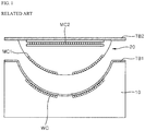
- FIG. 1 is a schematic view explaining an example of an induction heating device in related art.
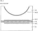
- FIG. 2 is a schematic view explaining another example of an induction heating device in related art.
- a top plate TB1 of an induction heating device 10 is concavely formed in a wok shape to heat an object such as a wok.
- a cup-shaped jig 20 that has a concave lower surface may provide a top plate TB2.
- the cup-shaped jig 20 may include repeating coils MC1 and MC2.
- the jig 20 may have a considerable size and weight, which may cause inconvenience for storage and transportation of the jig 20.
- the jig 20 does not include a capacitor in the jig 20, which may make it difficult to heat various cooking vessels as intended.
- an induction heating device 30 may be used to heat an object placed on a flat top plate TB without a support structure 40.
- the support structure 40 may be placed on the top plate TB.
- the support structure 40 may include repeating coils MC1 and MC2 inside thereof.
- a heating efficiency of the support structure 40 may be degraded due to the distance between the object and the working coil WC in the induction heating device 30 and due to a resonance point change of the repeating coils MC1 and MC2 inside of the support structure 40.
- the support structure 40 does not include a capacitor in the support structure 40, which may make it difficult to heat various cooking vessels as intended.
- One object of this application is to provide a support structure of an object to be heated that efficiently transmits an output of an induction heating device to the object.
- Another object of this application is to provide a support structure of an object to be heated that improves a temperature control efficiency of the object through an associated driving with an induction heating device.
- a support structure for an induction heating device that includes a working coil configured to heat an object.
- the support structure includes: a housing including an upper surface that is recessed downward and that is configured to seat the object; a repeating coil that is located inside of the housing, that is configured to generate magnetic induction or magnetic resonance with the working coil, and that is configured to heat the object on the upper surface of the housing based on magnetic induction or magnetic resonance with the working coil; and a compensation capacitor located inside of the housing and connected to the repeating coil, where the compensation capacitor is configured to control output of the repeating coil.
- Implementations according to this aspect may include one or more of the following features.
- the repeating coil may be arranged vertically between the working coil and a lowermost end of the object.
- a capacitance value of the compensation capacitor may be less than half of a capacitance value of the resonance capacitor.
- the support structure may further include a temperature sensor located inside of the housing and configured to sense a temperature of the object on the upper surface of the housing, and a communication module that is configured to wirelessly communicate with the temperature sensor and the induction heating device, that is configured to receive information regarding the temperature of the object from the temperature sensor, and that is configured to provide the information to the induction heating device.
- the temperature sensor may be arranged at a central region of the housing, and the housing may further include a lower surface that is spaced apart from the upper surface, where a distance between the upper surface and the lower surface of the housing decreases toward the central region of the housing.
- the repeating coil is configured to supply, to the temperature sensor and to the communication module, power generated through the magnetic induction or the magnetic resonance with the working coil.
- the upper surface of the housing includes a first horizontal portion that extends in a horizontal direction with respect to a lower surface of the housing, a curved surface portion that has a first end connected to an end of the first horizontal portion and that is curved downward to the lower surface of the housing, a vertical portion that extends from a second end of the curved surface portion in a vertical direction with respect to the lower surface of the housing, and a second horizontal portion that extends from an end of the vertical portion in the horizontal direction with respect to the lower surface of the housing.
- the support structure may further include a temperature sensor that is configured to sense a temperature of the object on the upper surface of the housing.
- the temperature sensor and the repeating coil may be arranged between the second horizontal portion and the lower surface of the housing.
- the temperature sensor is provided at a central region inside of the housing and is spaced apart from the repeating coil by a predetermined distance in a radial direction of the repeating coil.
- At least a portion of the second horizontal portion is configured to be spaced apart from the object in a state in which the curved surface portion contacts a bottom surface of the object. In some examples, a vertical distance between the first end of the curved surface portion and the second end of the curved surface portion is greater than a vertical distance between the second end of the curved surface portion and the second horizontal portion.
- the upper surface of the housing has a concave shape.
- the repeating coil is located vertically above the working coil.
- the upper surface of the housing may be configured to contact a lowermost end of the object vertically above the repeating coil.
- the temperature sensor is arranged at the central region of the housing at a position that defines a minimum distance between the upper surface and the lower surface of the housing.
- the repeating coil is arranged radially outward of the temperature sensor.
- the housing further includes a lower surface that has a planar shape and that is configured to contact a top plate of the induction heating device, the top plate being located vertically above the working coil.
- the repeating coil is located in a space defined between the upper surface of the housing and the lower surface of the housing.
- the compensation capacitor may be located in the space defined between the upper surface of the housing and the lower surface of the housing. The compensation capacitor may be located radially outward of the repeating coil.
- the support structure may further include a temperature sensor that is located in the space defined between the upper surface of the housing and the lower surface of the housing, where the temperature sensor is configured to sense a temperature of the object on the upper surface of the housing, and a communication module that is located in the space defined between the upper surface of the housing and the lower surface of the housing, where the communication module is configured to receive information regarding the temperature of the object from the temperature sensor and to provide the information to the induction heating device.
- the repeating coil may be arranged radially outward of the temperature sensor, and the communication module may be arranged radially outward of the repeating coil.
- the support structure may efficiently transmit the output of the induction heating device to an object such as a wok. Accordingly, the user can heat an object in a special shape such as a wok as well as other cooking vessels as intended, and furthermore, it is possible to shorten the cooking time when cooking by using the object to be heated such as the wok.
- the support structure may improve the temperature control efficiency of the object through the associated driving with the induction heating device.
- a fixed temperature control may be possible to cook using the object, which may improve a taste of cooking.
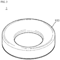
- FIG. 3 is a perspective view explaining an example support structure for an object that is to be heated.
- FIG. 4 is a cross-sectional view showing the support structure of FIG. 3 .
- FIG. 5 is a schematic view showing an example position of a repeating coil of FIG. 4 .
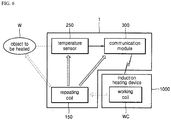
- FIG. 6 is a schematic view showing an example control flow and an example power flow between the support structure of FIG. 3 and the object.
- a support structure 1 is driven by a working coil and associated with the working coil (WC in FIG. 6 ) provided in an induction heating device (1000 in FIG. 6 ), and a specific matter thereof will be described later.
- the support structure 1 includes a housing 100, a repeating coil 150, a compensation capacitor 200, a temperature sensor 250, and a communication module 300.
- An upper surface 100a of the housing 100 can be concavely recessed downward and an object to be heated W can be arranged in the upper surface 100a of the housing 100.
- the housing 100 may include an upper surface 100a, a side surface 100b, and a lower surface 100c.
- the repeating coil 150, the compensation capacitor 200, the temperature sensor 250, and the communication module 300 may be included.
- the upper surface 100a may be concavely formed downward so that the object W that to be heated.
- the object W may be a cooking vessel such as a wok that is be stably supported as shown in FIG. 5 .
- an upper surface 100a of a housing 100 may include a first horizontal portion HP1, a curved portion CP, a vertical portion VP, and a second horizontal portion HP2.
- the first horizontal portion HP1 is connected to the side surface 100b of the housing 100 and may be formed to extend in a horizontal direction.
- the curved portion CP has one end connected to the first horizontal portion HP1, and may be formed to have a curved surface.
- the vertical portion VP has one end connected to the other end of the curved portion CP and may be formed to extend in a vertical direction (that is, a direction orthogonal to a horizontal direction).
- the second horizontal portion HP2 has one end connected to the other end of the vertical portion VP, and may be formed to extend in a horizontal direction (that is, a direction parallel to the first horizontal portion HP1).
- a repeating coil 150 is provided inside the housing 100 and can be driven through a magnetic induction (i.e., an electromagnetic induction) or a magnetic resonance (i.e., a magnetic resonance) with a working coil WC provided in an induction heating device.
- a magnetic induction i.e., an electromagnetic induction
- a magnetic resonance i.e., a magnetic resonance
- the working coil WC may correspond to a primary coil that transmits a wireless power
- the repeating coil 150 may correspond to a secondary coil that receives a wireless power.
- the repeating coil 150 can be driven by receiving a power through the magnetic induction or the magnetic resonance with the working coil WC.
- the repeating coil 150 may be arranged in an area between an intermediate point between the working coil WC and a lowermost end of an object to be heated W.
- the repeating coil 150 may be arranged in an area A between a lower end of a top plate TB of the induction heating device and a lowermost end of an object W.
- the area A has an area having the same size as an area B between the lower end of the top plate TB of the induction heating device and the working coil WC.
- the repeating coil 150 is arranged at the area A.
- the repeating coil 150 is driven through the magnetic induction or the magnetic resonance with the working coil WC, and thus, it is possible to supply the power generated based on a magnetic flux generated when driving the working coil WC to a temperature sensor 250 and a communication module 300.
- the repeating coil 150 may be arranged between the second horizontal portion HP2 and a lower surface 100c of the housing 100 and may be arranged so as to be spaced apart from the temperature sensor 250 in a horizontal direction by a predetermined space.
- a compensation capacitor 200 may be provided inside a housing 100 and may be connected to the repeating coil 150 in order to control an output of a repeating coil 150.
- the compensation capacitor 200 may be provided inside the housing 100 by being connected to the repeating coil 150 so that it is possible to efficiently transmit an output of the induction heating device to be object to be heated.
- a capacitance value of the compensation capacitor 200 is a half or more of a capacitance value of a resonance capacitor connected to the working coil WC, it may be difficult to effectively transmit the output of the induction heating device to the object to be heated. In such cases, the magnitude of a resonance current supplied to the working coil WC may have to be increased to provide an expected output to the object W.
- the capacitance value of the compensation capacitor 200 is less than a half (1/2) of the capacitance value of the resonance capacitor connected to the working coil WC to effectively transmit the output of the induction heating device to the object to be heated.
- the capacitance value of the compensation capacitor 200 may be set to be larger than or equal to a half (1/2) of the capacitance value of the resonance capacitor connected to the working coil WC.
- the capacitance value of the compensation capacitor 200 has a value less than a half 1/2 of the capacitance value of the resonance capacitor connected to the working coil WC.
- the temperature sensor 250 may be provided inside the housing 100 to sense a temperature of the object W arranged on the upper surface 100a of the housing 100.
- the temperature sensor 250 may be arranged at the center in the inside of the housing 100.
- an interval between the upper surface 100a and the lower surface 100c of the housing 100 is the narrowest at the center in the inside of the housing 100, so that the temperature sensor 250 can sense the temperature of the object W at a position adjacent to the object W.
- the temperature sensor 250 may be arranged between the second horizontal portion HP2 and a lower surface 100c of a housing 100 and may be provided at the center in the inside of the housing 100 so as to be spaced apart from the repeating coil 150 in the horizontal direction by the predetermined space.
- the temperature sensor 250 can provide information on the temperature of the object W to the communication module 300.
- the communication module 300 may receive information on the temperature of the object W, which is sensed by the temperature sensor 250, and may provide information to the induction heating device 1000 (see FIG. 6 ) through a wireless communication.
- the communication module 300 may provide information on the temperature of the object W to the induction heating device 1000 through the wireless communication such as Bluetooth, Zigbee, and WiFi, etc.
- FIG. 6 a control and a power flow of an object to be heated are shown.
- a temperature sensor 250 may sense a temperature of an object to be heated W and may provide information on a temperature to a communication module 300.
- the communication module 300 can provide information on the temperature of the object W supplied from the temperature sensor 250 to an induction heating device 1000 through a wireless communication.
- the induction heating device 1000 can control an output of a working coil WC (e.g., a frequency, a phase, and a magnitude of a resonance current provided to a working coil WC) based on information on the temperature of the object W provided from the communication module 300.
- a working coil WC e.g., a frequency, a phase, and a magnitude of a resonance current provided to a working coil WC
- a support structure 1 and the induction heating device 1000 are driven associated with each other through the communication module 300 so that a temperature control efficiency of the object to be heated can be improved.
- a repeating coil 150 receives or generates power wirelessly through a magnetic induction or a magnetic resonance with the working coil WC, and generates an eddy current to the object W by using a magnetic field generated by a received power to heat the object to be heated.
- the repeating coil 150 can provide the power generated through the magnetic induction or the magnetic resonance with the working coil WC to a component (for example, the temperature sensor 250 and the communication module 300, etc.) inside the housing 100.
- a component for example, the temperature sensor 250 and the communication module 300, etc.
- the support structure 1 can efficiently transmit an output of the induction heating device to the object to be heated.
- the user can heat an object to be heated in a special shape such as a wok as well as a general cooking vessel as intended, and furthermore, it is possible to shorten the cooking time when cooking by using the object to be cooked such as a wok.
- the support structure 1 can improve a temperature control efficiency of the object to be heated through an associated driving with the induction heating device. Furthermore, when cooking by using the object to be heated, a fixed temperature control is possible, so that the taste of food can be improved.
- the general cooking vessel when the user wishes to heat the general cooking vessel, the general cooking vessel is placed on the top plate (TB of FIG. 5 ) of the induction heating device without the support structure 1 and heated.
- the wok when the user wishes to heat the wok, the wok is placed on the support structure 1 and heated, after arranging the support structure 1 on the top plate (TB of FIG. 5 ) of the induction heating device.
- the user may place the general cooking vessel on the support structure 1 and heat it.
Landscapes
- Physics & Mathematics (AREA)
- Electromagnetism (AREA)
- Engineering & Computer Science (AREA)
- Computer Networks & Wireless Communication (AREA)
- Power Engineering (AREA)
- Induction Heating Cooking Devices (AREA)
- General Induction Heating (AREA)
Abstract
Description
- This application relates to a support structure that is configured to be driven by a working coil provided in an induction heating device to heat an object.
- Cooking devices may use various methods to heat food. For example, a gas range uses gas as fuel. In some examples, cooking devices may heat an object such as a cooking vessel or a pot, for example, using electricity without using gas.
- A method of heating an object using electricity may be divided into a resistive heating method and an induction heating method. In the electrical resistive method, heat may be generated based on current flowing through a non-metallic heating element such as silicon carbide or a metal resistance wire. In this method, heat may be transmitted to the object through a radiation or conduction to heat the object. In the induction heating method, an eddy current may be generated in the object made of metal based on a high-frequency power of a predetermined magnitude applied to the coil. In this method, the loaded object may be heated by the eddy current generated based on magnetic field around the working coil.
- An induction heating device is a heating device that uses the induction heating method.
- In some cases, the induction heating device may include a flat top plate. In such cases, it may be difficult to heat an object such as a wok that has a concave lower surface. In some cases, a large resonance current may be necessary to heat the object.
-
FIG. 1 is a schematic view explaining an example of an induction heating device in related art.FIG. 2 is a schematic view explaining another example of an induction heating device in related art. - In the example shown in
FIG. 1 , a top plate TB1 of aninduction heating device 10 is concavely formed in a wok shape to heat an object such as a wok. - In some cases, when other cooking vessels having a flat shape are to be heated, a cup-
shaped jig 20 that has a concave lower surface may provide a top plate TB2. The cup-shaped jig 20 may include repeating coils MC1 and MC2. - In some cases, the
jig 20 may have a considerable size and weight, which may cause inconvenience for storage and transportation of thejig 20. Thejig 20 does not include a capacitor in thejig 20, which may make it difficult to heat various cooking vessels as intended. - In the example shown in
FIG. 2 , aninduction heating device 30 may be used to heat an object placed on a flat top plate TB without asupport structure 40. In the case of heating an object such as a wok, thesupport structure 40 may be placed on the top plate TB. Thesupport structure 40 may include repeating coils MC1 and MC2 inside thereof. - In some cases, a heating efficiency of the
support structure 40 may be degraded due to the distance between the object and the working coil WC in theinduction heating device 30 and due to a resonance point change of the repeating coils MC1 and MC2 inside of thesupport structure 40. Thesupport structure 40 does not include a capacitor in thesupport structure 40, which may make it difficult to heat various cooking vessels as intended. - The present invention is defined by the independent claim. The dependent claims relate to further aspects of the invention.
- One object of this application is to provide a support structure of an object to be heated that efficiently transmits an output of an induction heating device to the object.
- Another object of this application is to provide a support structure of an object to be heated that improves a temperature control efficiency of the object through an associated driving with an induction heating device.
- The objects of this application are not limited to the above-mentioned objects, and the other objects and the advantages of this application, which are not mentioned, can be understood by the following description, and more clearly understood by the implementations of this application. It will be also readily seen that the objects and the advantages of this application may be realized by means indicated in the patent claims and a combination thereof.
- According to one aspect of the subject matter described in this application, a support structure is disclosed for an induction heating device that includes a working coil configured to heat an object. The support structure includes: a housing including an upper surface that is recessed downward and that is configured to seat the object; a repeating coil that is located inside of the housing, that is configured to generate magnetic induction or magnetic resonance with the working coil, and that is configured to heat the object on the upper surface of the housing based on magnetic induction or magnetic resonance with the working coil; and a compensation capacitor located inside of the housing and connected to the repeating coil, where the compensation capacitor is configured to control output of the repeating coil.
- Implementations according to this aspect may include one or more of the following features. For example, the repeating coil may be arranged vertically between the working coil and a lowermost end of the object. In some examples where the induction heating device further includes a resonance capacitor connected to the working coil, a capacitance value of the compensation capacitor may be less than half of a capacitance value of the resonance capacitor. In some examples, the support structure may further include a temperature sensor located inside of the housing and configured to sense a temperature of the object on the upper surface of the housing, and a communication module that is configured to wirelessly communicate with the temperature sensor and the induction heating device, that is configured to receive information regarding the temperature of the object from the temperature sensor, and that is configured to provide the information to the induction heating device.
- In some examples, the temperature sensor may be arranged at a central region of the housing, and the housing may further include a lower surface that is spaced apart from the upper surface, where a distance between the upper surface and the lower surface of the housing decreases toward the central region of the housing. In some examples, the repeating coil is configured to supply, to the temperature sensor and to the communication module, power generated through the magnetic induction or the magnetic resonance with the working coil.
- In some implementations, the upper surface of the housing includes a first horizontal portion that extends in a horizontal direction with respect to a lower surface of the housing, a curved surface portion that has a first end connected to an end of the first horizontal portion and that is curved downward to the lower surface of the housing, a vertical portion that extends from a second end of the curved surface portion in a vertical direction with respect to the lower surface of the housing, and a second horizontal portion that extends from an end of the vertical portion in the horizontal direction with respect to the lower surface of the housing.
- In some examples, the support structure may further include a temperature sensor that is configured to sense a temperature of the object on the upper surface of the housing. The temperature sensor and the repeating coil may be arranged between the second horizontal portion and the lower surface of the housing. The temperature sensor is provided at a central region inside of the housing and is spaced apart from the repeating coil by a predetermined distance in a radial direction of the repeating coil.
- In some examples, at least a portion of the second horizontal portion is configured to be spaced apart from the object in a state in which the curved surface portion contacts a bottom surface of the object. In some examples, a vertical distance between the first end of the curved surface portion and the second end of the curved surface portion is greater than a vertical distance between the second end of the curved surface portion and the second horizontal portion.
- In some implementations, the upper surface of the housing has a concave shape. In some examples, the repeating coil is located vertically above the working coil. The upper surface of the housing may be configured to contact a lowermost end of the object vertically above the repeating coil. In some examples, the temperature sensor is arranged at the central region of the housing at a position that defines a minimum distance between the upper surface and the lower surface of the housing. In some examples, the repeating coil is arranged radially outward of the temperature sensor.
- In some implementations, the housing further includes a lower surface that has a planar shape and that is configured to contact a top plate of the induction heating device, the top plate being located vertically above the working coil. In some examples, the repeating coil is located in a space defined between the upper surface of the housing and the lower surface of the housing. The compensation capacitor may be located in the space defined between the upper surface of the housing and the lower surface of the housing. The compensation capacitor may be located radially outward of the repeating coil.
- In some implementations, the support structure may further include a temperature sensor that is located in the space defined between the upper surface of the housing and the lower surface of the housing, where the temperature sensor is configured to sense a temperature of the object on the upper surface of the housing, and a communication module that is located in the space defined between the upper surface of the housing and the lower surface of the housing, where the communication module is configured to receive information regarding the temperature of the object from the temperature sensor and to provide the information to the induction heating device. The repeating coil may be arranged radially outward of the temperature sensor, and the communication module may be arranged radially outward of the repeating coil.
- The support structure may efficiently transmit the output of the induction heating device to an object such as a wok. Accordingly, the user can heat an object in a special shape such as a wok as well as other cooking vessels as intended, and furthermore, it is possible to shorten the cooking time when cooking by using the object to be heated such as the wok.
- Further, the support structure may improve the temperature control efficiency of the object through the associated driving with the induction heating device. In some examples, a fixed temperature control may be possible to cook using the object, which may improve a taste of cooking.
- Hereafter, a specific effect of this application, in addition to the above-mentioned effect, will be described together while describing a specific matter for implementing this application.
-
FIG. 1 is a schematic view explaining an example of an induction heating device in related art. -
FIG. 2 is a schematic view explaining another example of an induction heating device in related art. -
FIG. 3 is a perspective view showing an example support structure according to the present disclosure. -
FIG. 4 is a cross-sectional view showing the support structure ofFIG. 3 . -
FIG. 5 is a schematic view showing an example repeating coil of the support structure ofFIG. 4 and an example position of the repeating coil. -
FIG. 6 is a schematic view illustrating an example control flow and an example power flow between the support structure ofFIG. 3 and an example object. - Hereinafter, the example implementations of this application will be described in detail with reference to the accompanying drawings. In the drawings, the like reference numerals are used to indicate the same or similar components.
- Hereinafter, a support structure for an object in accordance with an exemplary implementation of this application will be described.
-
FIG. 3 is a perspective view explaining an example support structure for an object that is to be heated.FIG. 4 is a cross-sectional view showing the support structure ofFIG. 3 .FIG. 5 is a schematic view showing an example position of a repeating coil ofFIG. 4 .FIG. 6 is a schematic view showing an example control flow and an example power flow between the support structure ofFIG. 3 and the object. - In some implementations, a
support structure 1 is driven by a working coil and associated with the working coil (WC inFIG. 6 ) provided in an induction heating device (1000 inFIG. 6 ), and a specific matter thereof will be described later. - Referring to
FIGS. 3 to 5 , thesupport structure 1 includes ahousing 100, a repeatingcoil 150, acompensation capacitor 200, atemperature sensor 250, and acommunication module 300. - An
upper surface 100a of thehousing 100 can be concavely recessed downward and an object to be heated W can be arranged in theupper surface 100a of thehousing 100. - For example, the
housing 100 may include anupper surface 100a, aside surface 100b, and alower surface 100c. In an inside thehousing 100, the repeatingcoil 150, thecompensation capacitor 200, thetemperature sensor 250, and thecommunication module 300 may be included. - Here, the
upper surface 100a may be concavely formed downward so that the object W that to be heated. For example, the object W may be a cooking vessel such as a wok that is be stably supported as shown inFIG. 5 . - In some examples, an
upper surface 100a of ahousing 100 may include a first horizontal portion HP1, a curved portion CP, a vertical portion VP, and a second horizontal portion HP2. - For example, the first horizontal portion HP1 is connected to the
side surface 100b of thehousing 100 and may be formed to extend in a horizontal direction. The curved portion CP has one end connected to the first horizontal portion HP1, and may be formed to have a curved surface. In addition, the vertical portion VP has one end connected to the other end of the curved portion CP and may be formed to extend in a vertical direction (that is, a direction orthogonal to a horizontal direction). The second horizontal portion HP2 has one end connected to the other end of the vertical portion VP, and may be formed to extend in a horizontal direction (that is, a direction parallel to the first horizontal portion HP1). - A repeating
coil 150 is provided inside thehousing 100 and can be driven through a magnetic induction (i.e., an electromagnetic induction) or a magnetic resonance (i.e., a magnetic resonance) with a working coil WC provided in an induction heating device. - In some implementations, the working coil WC may correspond to a primary coil that transmits a wireless power, and the repeating
coil 150 may correspond to a secondary coil that receives a wireless power. In the same or other implementations, the repeatingcoil 150 can be driven by receiving a power through the magnetic induction or the magnetic resonance with the working coil WC. - In some implementations, as shown in
FIG. 5 , the repeatingcoil 150 may be arranged in an area between an intermediate point between the working coil WC and a lowermost end of an object to be heated W. For example, the repeatingcoil 150 may be arranged in an area A between a lower end of a top plate TB of the induction heating device and a lowermost end of an object W. In some cases, the area A has an area having the same size as an area B between the lower end of the top plate TB of the induction heating device and the working coil WC. - In some examples, as the distance between the repeating
coil 150 and the working coil WC is closer, an energy transfer performance between two coils (that is, a coupling coefficient between the repeatingcoil 150 and the working coil WC becomes similar to a coupling coefficient between the working coil WC and the object W, and thus, a function of the repeatingcoil 150 can be degraded, which is an intermediate medium of a power transmission) can be degraded. Thus, in order to prevent this, the repeatingcoil 150 is arranged at the area A. - In addition, as mentioned above, the repeating
coil 150 is driven through the magnetic induction or the magnetic resonance with the working coil WC, and thus, it is possible to supply the power generated based on a magnetic flux generated when driving the working coil WC to atemperature sensor 250 and acommunication module 300. - In some implementations, the repeating
coil 150 may be arranged between the second horizontal portion HP2 and alower surface 100c of thehousing 100 and may be arranged so as to be spaced apart from thetemperature sensor 250 in a horizontal direction by a predetermined space. - A
compensation capacitor 200 may be provided inside ahousing 100 and may be connected to the repeatingcoil 150 in order to control an output of a repeatingcoil 150. - In some implementations, the
compensation capacitor 200 may be provided inside thehousing 100 by being connected to the repeatingcoil 150 so that it is possible to efficiently transmit an output of the induction heating device to be object to be heated. - In some cases, when a capacitance value of the
compensation capacitor 200 is a half or more of a capacitance value of a resonance capacitor connected to the working coil WC, it may be difficult to effectively transmit the output of the induction heating device to the object to be heated. In such cases, the magnitude of a resonance current supplied to the working coil WC may have to be increased to provide an expected output to the object W. - In some implementations, the capacitance value of the
compensation capacitor 200 is less than a half (1/2) of the capacitance value of the resonance capacitor connected to the working coil WC to effectively transmit the output of the induction heating device to the object to be heated. - In some implementations, the capacitance value of the
compensation capacitor 200 may be set to be larger than or equal to a half (1/2) of the capacitance value of the resonance capacitor connected to the working coil WC. However, for convenience of explanation, it will be described by having an example that the capacitance value of thecompensation capacitor 200 has a value less than ahalf 1/2 of the capacitance value of the resonance capacitor connected to the working coil WC. - The
temperature sensor 250 may be provided inside thehousing 100 to sense a temperature of the object W arranged on theupper surface 100a of thehousing 100. - For example, the
temperature sensor 250 may be arranged at the center in the inside of thehousing 100. - Here, an interval between the
upper surface 100a and thelower surface 100c of thehousing 100 is the narrowest at the center in the inside of thehousing 100, so that thetemperature sensor 250 can sense the temperature of the object W at a position adjacent to the object W. - In addition, the
temperature sensor 250 may be arranged between the second horizontal portion HP2 and alower surface 100c of ahousing 100 and may be provided at the center in the inside of thehousing 100 so as to be spaced apart from the repeatingcoil 150 in the horizontal direction by the predetermined space. - In some implementations, the
temperature sensor 250 can provide information on the temperature of the object W to thecommunication module 300. - The
communication module 300 may receive information on the temperature of the object W, which is sensed by thetemperature sensor 250, and may provide information to the induction heating device 1000 (seeFIG. 6 ) through a wireless communication. - In some implementations, the
communication module 300 may provide information on the temperature of the object W to theinduction heating device 1000 through the wireless communication such as Bluetooth, Zigbee, and WiFi, etc. - Here, referring to
FIG. 6 , a control and a power flow of an object to be heated are shown. - In some implementations, a
temperature sensor 250 may sense a temperature of an object to be heated W and may provide information on a temperature to acommunication module 300. In addition, thecommunication module 300 can provide information on the temperature of the object W supplied from thetemperature sensor 250 to aninduction heating device 1000 through a wireless communication. - In some implementations, the
induction heating device 1000 can control an output of a working coil WC (e.g., a frequency, a phase, and a magnitude of a resonance current provided to a working coil WC) based on information on the temperature of the object W provided from thecommunication module 300. - That is, a
support structure 1 and theinduction heating device 1000 are driven associated with each other through thecommunication module 300 so that a temperature control efficiency of the object to be heated can be improved. - In some implementations, a repeating
coil 150 receives or generates power wirelessly through a magnetic induction or a magnetic resonance with the working coil WC, and generates an eddy current to the object W by using a magnetic field generated by a received power to heat the object to be heated. - The repeating
coil 150 can provide the power generated through the magnetic induction or the magnetic resonance with the working coil WC to a component (for example, thetemperature sensor 250 and thecommunication module 300, etc.) inside thehousing 100. - As mentioned above, the
support structure 1 can efficiently transmit an output of the induction heating device to the object to be heated. The user can heat an object to be heated in a special shape such as a wok as well as a general cooking vessel as intended, and furthermore, it is possible to shorten the cooking time when cooking by using the object to be cooked such as a wok. - In addition, the
support structure 1 can improve a temperature control efficiency of the object to be heated through an associated driving with the induction heating device. Furthermore, when cooking by using the object to be heated, a fixed temperature control is possible, so that the taste of food can be improved. - In some implementations, when the user wishes to heat the general cooking vessel, the general cooking vessel is placed on the top plate (TB of
FIG. 5 ) of the induction heating device without thesupport structure 1 and heated. In addition, when the user wishes to heat the wok, the wok is placed on thesupport structure 1 and heated, after arranging thesupport structure 1 on the top plate (TB ofFIG. 5 ) of the induction heating device. Of course, the user may place the general cooking vessel on thesupport structure 1 and heat it. - Since various substitutions, changes, and modifications can be made within the scope that does not deviate the technical idea of this application for those skilled in the art to which this application pertains, the above-mentioned application is not limited by the above-mentioned implementations and the accompanying drawings.
Claims (8)
- A support structure (1) for an object to be heated that is driven by being associated with a working coil (WC) provided in an induction heating device (1000), comprising:a housing (100) comprising an upper surface (100a) that is concavely formed downward and an object to be heated is arranged on the upper surface (100a);a repeating coil (150) that is provided inside the housing (100) and driven through a magnetic induction or a magnetic resonance with the working coil (WC); anda compensation capacitor (200) that is provided inside the housing (100) and connected to the repeating coil (150) for controlling an output of the repeating coil (150).
- The support structure (1) for an object to be heated of claim 1, wherein the repeating coil (150) is arranged in an area from an intermediate point between the working coil (WC) and a lowermost end of the object to be heated to the lowermost end of the object to be heated.
- The support structure (1) for an object to be heated of claim 1 or 2, wherein a capacitance value of the compensation capacitor (200) comprises a value less than a half of a capacitance value of a resonance capacitor connected to the working coil (WC).
- The support structure (1) for an object to be heated of any one of claims 1 to 3, further comprising:a temperature sensor (250) that is provided in the housing (100) and configured to sense a temperature of the object to be heated arranged on the upper surface (100a) of the housing (100); anda communication module (300) configured to receive information on the temperature of the object to be heated from the temperature sensor (250) and to provide information to the induction heating device (1000) through a wireless communication.
- The support structure (1) for an object to be heated of claim 4,
wherein the temperature sensor (250) is arranged at the center of the inside of the housing (100), and
wherein an interval between the upper surface (100a) and a lower surface (100c) of the housing (100) is narrowest at the center of an inside of the housing (100). - The support structure (1) for an object to be heated of claim 4 or 5, wherein the repeating coil (150) is configured to supply a power generated through the magnetic induction or the magnetic resonance with the working coil (WC) to the temperature sensor (250) and the communication module (300).
- The support structure (1) for an object to be heated of any one of claims 1 to 6,
wherein the upper surface (100a) of the housing (100) comprises:a first horizontal portion (HP1),a curved surface portion (CP) with one end connected to the first horizontal portion (HP1),a vertical portion (VP) that the one end is connected to the other end of the curved surface portion (CP), anda second horizontal portion (HP2) with one end connected to the other end of the vertical portion (VP). - The support structure (1) for an object to be heated of claim 7, further comprising the temperature sensor (250) that is configured to sense the temperature of the object to be heated arranged in the upper surface (100a) of the housing (100),
wherein the temperature sensor (250) and the repeating coil (150) are arranged between a lower surface of the second horizontal portion (HP2) and the housing (100), and
wherein the temperature sensor (250) is provided at the center inside the housing (100) so as to be spaced apart from the repeating coil (150) by a predetermine space.
Applications Claiming Priority (1)
| Application Number | Priority Date | Filing Date | Title |
|---|---|---|---|
| KR1020170128282A KR102355669B1 (en) | 2017-09-29 | 2017-09-29 | Support structure for the object to be heated |
Publications (2)
| Publication Number | Publication Date |
|---|---|
| EP3462816A1 true EP3462816A1 (en) | 2019-04-03 |
| EP3462816B1 EP3462816B1 (en) | 2020-06-17 |
Family
ID=63683740
Family Applications (1)
| Application Number | Title | Priority Date | Filing Date |
|---|---|---|---|
| EP18196543.5A Active EP3462816B1 (en) | 2017-09-29 | 2018-09-25 | Support structure for object to be heated |
Country Status (3)
| Country | Link |
|---|---|
| US (1) | US11265972B2 (en) |
| EP (1) | EP3462816B1 (en) |
| KR (1) | KR102355669B1 (en) |
Cited By (3)
| Publication number | Priority date | Publication date | Assignee | Title |
|---|---|---|---|---|
| EP3490340A1 (en) * | 2017-11-22 | 2019-05-29 | Arpa Sasu | Method for inductively heating an inductively heatable cooking vessel, transmission coaster and induction heating cooker for carrying out the method |
| EP3869919A1 (en) * | 2020-02-18 | 2021-08-25 | LG Electronics Inc. | Cooking apparatus and cooking system including the same |
| GB2625113A (en) * | 2022-12-07 | 2024-06-12 | Dyson Technology Ltd | Heating system |
Families Citing this family (2)
| Publication number | Priority date | Publication date | Assignee | Title |
|---|---|---|---|---|
| CN112217291A (en) * | 2019-07-11 | 2021-01-12 | 泰科电子(上海)有限公司 | Sensing device and electromagnetic device system comprising same |
| JP7644626B2 (en) * | 2021-03-04 | 2025-03-12 | 三星電子株式会社 | Electromagnetic Induction Device |
Citations (4)
| Publication number | Priority date | Publication date | Assignee | Title |
|---|---|---|---|---|
| JPH06338382A (en) * | 1993-05-27 | 1994-12-06 | Sanyo Electric Co Ltd | Electromagnetic induction type heating cooler |
| DE102010020189A1 (en) * | 2009-05-15 | 2011-01-27 | BSH Bosch und Siemens Hausgeräte GmbH | Heating device for use in induction hob to heat cookware element i.e. wok, has upper induction coil producing induced current in cookware element and connected to lower induction coil, where coils are of different forms |
| EP2408261A1 (en) * | 2010-07-17 | 2012-01-18 | Electrolux Home Products Corporation N.V. | A wok support for an induction hob |
| WO2013103939A1 (en) * | 2012-01-08 | 2013-07-11 | Access Business Group International Llc | Inductive cooking system |
Family Cites Families (5)
| Publication number | Priority date | Publication date | Assignee | Title |
|---|---|---|---|---|
| KR100526206B1 (en) * | 2003-03-21 | 2005-11-08 | 삼성전자주식회사 | Cooking Apparatus |
| KR100661226B1 (en) * | 2005-12-02 | 2006-12-22 | 엘지전자 주식회사 | Load sensing device and method of electric cooker |
| US8350196B2 (en) * | 2008-02-06 | 2013-01-08 | Tsi Technologies Llc | Radio frequency antenna for heating devices |
| US20160014849A1 (en) * | 2013-01-14 | 2016-01-14 | Breville Pty Limited | Multi Cooker |
| CN104869678B (en) * | 2013-12-17 | 2017-04-12 | Bsh家用电器有限公司 | Induction cooking bench adapter |
-
2017
- 2017-09-29 KR KR1020170128282A patent/KR102355669B1/en active Active
-
2018
- 2018-09-25 EP EP18196543.5A patent/EP3462816B1/en active Active
- 2018-09-28 US US16/145,403 patent/US11265972B2/en active Active
Patent Citations (4)
| Publication number | Priority date | Publication date | Assignee | Title |
|---|---|---|---|---|
| JPH06338382A (en) * | 1993-05-27 | 1994-12-06 | Sanyo Electric Co Ltd | Electromagnetic induction type heating cooler |
| DE102010020189A1 (en) * | 2009-05-15 | 2011-01-27 | BSH Bosch und Siemens Hausgeräte GmbH | Heating device for use in induction hob to heat cookware element i.e. wok, has upper induction coil producing induced current in cookware element and connected to lower induction coil, where coils are of different forms |
| EP2408261A1 (en) * | 2010-07-17 | 2012-01-18 | Electrolux Home Products Corporation N.V. | A wok support for an induction hob |
| WO2013103939A1 (en) * | 2012-01-08 | 2013-07-11 | Access Business Group International Llc | Inductive cooking system |
Cited By (4)
| Publication number | Priority date | Publication date | Assignee | Title |
|---|---|---|---|---|
| EP3490340A1 (en) * | 2017-11-22 | 2019-05-29 | Arpa Sasu | Method for inductively heating an inductively heatable cooking vessel, transmission coaster and induction heating cooker for carrying out the method |
| EP3869919A1 (en) * | 2020-02-18 | 2021-08-25 | LG Electronics Inc. | Cooking apparatus and cooking system including the same |
| US11785676B2 (en) | 2020-02-18 | 2023-10-10 | Lg Electronics Inc. | Cooking apparatus and cooking system including the same |
| GB2625113A (en) * | 2022-12-07 | 2024-06-12 | Dyson Technology Ltd | Heating system |
Also Published As
| Publication number | Publication date |
|---|---|
| US20190104570A1 (en) | 2019-04-04 |
| US11265972B2 (en) | 2022-03-01 |
| KR20190038169A (en) | 2019-04-08 |
| KR102355669B1 (en) | 2022-01-25 |
| EP3462816B1 (en) | 2020-06-17 |
Similar Documents
| Publication | Publication Date | Title |
|---|---|---|
| EP3462816B1 (en) | Support structure for object to be heated | |
| EP2048914B1 (en) | A cooking device having an induction heating element | |
| US20090084777A1 (en) | Cooking device having an induction heating element | |
| KR20110104987A (en) | Smart cookware | |
| US6291805B1 (en) | Device for induction heating of a cooking vessel | |
| CN101485231A (en) | Hob allowing the temperature of a culinary article to be detected | |
| EP3616573A1 (en) | Smart kettle using induction heating | |
| US11166347B2 (en) | Induction heating device | |
| CN104869678B (en) | Induction cooking bench adapter | |
| KR20150104657A (en) | Container heating apparatus | |
| US7385162B2 (en) | Heater unit and electric cooker equipped therewith | |
| EP3550934A1 (en) | Device and method for wireless power transfer | |
| JP2018092709A (en) | Magnetic resonance heat generator | |
| KR101807826B1 (en) | power supply apparatus using as a two-way induction cooker and wireless power transmitting device | |
| US20200404750A1 (en) | Cooking system | |
| KR101110629B1 (en) | Small induction heater | |
| CN106923645B (en) | Cooking apparatus | |
| JP3292059B2 (en) | Electric rice cooker | |
| KR20200109091A (en) | Cooking apparatus | |
| CN204105719U (en) | Pot lid of electric pressure appliance and electric pressure appliance | |
| EP3869916B1 (en) | COOKER | |
| EP3698682A1 (en) | Wireless induction heating cooker with improved heat conduction efficiency and wireless induction heating system comprising the same | |
| KR20230140983A (en) | Electric stove and method for controlling the same | |
| US12603526B1 (en) | Hybrid wireless power device and method | |
| JP4843460B2 (en) | Induction heating cooker |
Legal Events
| Date | Code | Title | Description |
|---|---|---|---|
| PUAI | Public reference made under article 153(3) epc to a published international application that has entered the european phase |
Free format text: ORIGINAL CODE: 0009012 |
|
| STAA | Information on the status of an ep patent application or granted ep patent |
Free format text: STATUS: THE APPLICATION HAS BEEN PUBLISHED |
|
| AK | Designated contracting states |
Kind code of ref document: A1 Designated state(s): AL AT BE BG CH CY CZ DE DK EE ES FI FR GB GR HR HU IE IS IT LI LT LU LV MC MK MT NL NO PL PT RO RS SE SI SK SM TR |
|
| AX | Request for extension of the european patent |
Extension state: BA ME |
|
| STAA | Information on the status of an ep patent application or granted ep patent |
Free format text: STATUS: REQUEST FOR EXAMINATION WAS MADE |
|
| 17P | Request for examination filed |
Effective date: 20190808 |
|
| RBV | Designated contracting states (corrected) |
Designated state(s): AL AT BE BG CH CY CZ DE DK EE ES FI FR GB GR HR HU IE IS IT LI LT LU LV MC MK MT NL NO PL PT RO RS SE SI SK SM TR |
|
| GRAP | Despatch of communication of intention to grant a patent |
Free format text: ORIGINAL CODE: EPIDOSNIGR1 |
|
| STAA | Information on the status of an ep patent application or granted ep patent |
Free format text: STATUS: GRANT OF PATENT IS INTENDED |
|
| RIC1 | Information provided on ipc code assigned before grant |
Ipc: H05B 6/12 20060101AFI20191211BHEP |
|
| INTG | Intention to grant announced |
Effective date: 20200108 |
|
| GRAS | Grant fee paid |
Free format text: ORIGINAL CODE: EPIDOSNIGR3 |
|
| GRAA | (expected) grant |
Free format text: ORIGINAL CODE: 0009210 |
|
| STAA | Information on the status of an ep patent application or granted ep patent |
Free format text: STATUS: THE PATENT HAS BEEN GRANTED |
|
| AK | Designated contracting states |
Kind code of ref document: B1 Designated state(s): AL AT BE BG CH CY CZ DE DK EE ES FI FR GB GR HR HU IE IS IT LI LT LU LV MC MK MT NL NO PL PT RO RS SE SI SK SM TR |
|
| REG | Reference to a national code |
Ref country code: GB Ref legal event code: FG4D |
|
| REG | Reference to a national code |
Ref country code: CH Ref legal event code: EP |
|
| REG | Reference to a national code |
Ref country code: IE Ref legal event code: FG4D |
|
| REG | Reference to a national code |
Ref country code: DE Ref legal event code: R096 Ref document number: 602018005351 Country of ref document: DE |
|
| REG | Reference to a national code |
Ref country code: AT Ref legal event code: REF Ref document number: 1282917 Country of ref document: AT Kind code of ref document: T Effective date: 20200715 |
|
| PG25 | Lapsed in a contracting state [announced via postgrant information from national office to epo] |
Ref country code: SE Free format text: LAPSE BECAUSE OF FAILURE TO SUBMIT A TRANSLATION OF THE DESCRIPTION OR TO PAY THE FEE WITHIN THE PRESCRIBED TIME-LIMIT Effective date: 20200617 Ref country code: FI Free format text: LAPSE BECAUSE OF FAILURE TO SUBMIT A TRANSLATION OF THE DESCRIPTION OR TO PAY THE FEE WITHIN THE PRESCRIBED TIME-LIMIT Effective date: 20200617 Ref country code: NO Free format text: LAPSE BECAUSE OF FAILURE TO SUBMIT A TRANSLATION OF THE DESCRIPTION OR TO PAY THE FEE WITHIN THE PRESCRIBED TIME-LIMIT Effective date: 20200917 Ref country code: GR Free format text: LAPSE BECAUSE OF FAILURE TO SUBMIT A TRANSLATION OF THE DESCRIPTION OR TO PAY THE FEE WITHIN THE PRESCRIBED TIME-LIMIT Effective date: 20200918 Ref country code: LT Free format text: LAPSE BECAUSE OF FAILURE TO SUBMIT A TRANSLATION OF THE DESCRIPTION OR TO PAY THE FEE WITHIN THE PRESCRIBED TIME-LIMIT Effective date: 20200617 |
|
| REG | Reference to a national code |
Ref country code: LT Ref legal event code: MG4D |
|
| REG | Reference to a national code |
Ref country code: NL Ref legal event code: MP Effective date: 20200617 |
|
| PG25 | Lapsed in a contracting state [announced via postgrant information from national office to epo] |
Ref country code: LV Free format text: LAPSE BECAUSE OF FAILURE TO SUBMIT A TRANSLATION OF THE DESCRIPTION OR TO PAY THE FEE WITHIN THE PRESCRIBED TIME-LIMIT Effective date: 20200617 Ref country code: RS Free format text: LAPSE BECAUSE OF FAILURE TO SUBMIT A TRANSLATION OF THE DESCRIPTION OR TO PAY THE FEE WITHIN THE PRESCRIBED TIME-LIMIT Effective date: 20200617 Ref country code: BG Free format text: LAPSE BECAUSE OF FAILURE TO SUBMIT A TRANSLATION OF THE DESCRIPTION OR TO PAY THE FEE WITHIN THE PRESCRIBED TIME-LIMIT Effective date: 20200917 Ref country code: HR Free format text: LAPSE BECAUSE OF FAILURE TO SUBMIT A TRANSLATION OF THE DESCRIPTION OR TO PAY THE FEE WITHIN THE PRESCRIBED TIME-LIMIT Effective date: 20200617 |
|
| REG | Reference to a national code |
Ref country code: AT Ref legal event code: MK05 Ref document number: 1282917 Country of ref document: AT Kind code of ref document: T Effective date: 20200617 |
|
| PG25 | Lapsed in a contracting state [announced via postgrant information from national office to epo] |
Ref country code: NL Free format text: LAPSE BECAUSE OF FAILURE TO SUBMIT A TRANSLATION OF THE DESCRIPTION OR TO PAY THE FEE WITHIN THE PRESCRIBED TIME-LIMIT Effective date: 20200617 Ref country code: AL Free format text: LAPSE BECAUSE OF FAILURE TO SUBMIT A TRANSLATION OF THE DESCRIPTION OR TO PAY THE FEE WITHIN THE PRESCRIBED TIME-LIMIT Effective date: 20200617 |
|
| PG25 | Lapsed in a contracting state [announced via postgrant information from national office to epo] |
Ref country code: RO Free format text: LAPSE BECAUSE OF FAILURE TO SUBMIT A TRANSLATION OF THE DESCRIPTION OR TO PAY THE FEE WITHIN THE PRESCRIBED TIME-LIMIT Effective date: 20200617 Ref country code: IT Free format text: LAPSE BECAUSE OF FAILURE TO SUBMIT A TRANSLATION OF THE DESCRIPTION OR TO PAY THE FEE WITHIN THE PRESCRIBED TIME-LIMIT Effective date: 20200617 Ref country code: CZ Free format text: LAPSE BECAUSE OF FAILURE TO SUBMIT A TRANSLATION OF THE DESCRIPTION OR TO PAY THE FEE WITHIN THE PRESCRIBED TIME-LIMIT Effective date: 20200617 Ref country code: SM Free format text: LAPSE BECAUSE OF FAILURE TO SUBMIT A TRANSLATION OF THE DESCRIPTION OR TO PAY THE FEE WITHIN THE PRESCRIBED TIME-LIMIT Effective date: 20200617 Ref country code: EE Free format text: LAPSE BECAUSE OF FAILURE TO SUBMIT A TRANSLATION OF THE DESCRIPTION OR TO PAY THE FEE WITHIN THE PRESCRIBED TIME-LIMIT Effective date: 20200617 Ref country code: AT Free format text: LAPSE BECAUSE OF FAILURE TO SUBMIT A TRANSLATION OF THE DESCRIPTION OR TO PAY THE FEE WITHIN THE PRESCRIBED TIME-LIMIT Effective date: 20200617 Ref country code: ES Free format text: LAPSE BECAUSE OF FAILURE TO SUBMIT A TRANSLATION OF THE DESCRIPTION OR TO PAY THE FEE WITHIN THE PRESCRIBED TIME-LIMIT Effective date: 20200617 Ref country code: PT Free format text: LAPSE BECAUSE OF FAILURE TO SUBMIT A TRANSLATION OF THE DESCRIPTION OR TO PAY THE FEE WITHIN THE PRESCRIBED TIME-LIMIT Effective date: 20201019 |
|
| PG25 | Lapsed in a contracting state [announced via postgrant information from national office to epo] |
Ref country code: SK Free format text: LAPSE BECAUSE OF FAILURE TO SUBMIT A TRANSLATION OF THE DESCRIPTION OR TO PAY THE FEE WITHIN THE PRESCRIBED TIME-LIMIT Effective date: 20200617 Ref country code: PL Free format text: LAPSE BECAUSE OF FAILURE TO SUBMIT A TRANSLATION OF THE DESCRIPTION OR TO PAY THE FEE WITHIN THE PRESCRIBED TIME-LIMIT Effective date: 20200617 Ref country code: IS Free format text: LAPSE BECAUSE OF FAILURE TO SUBMIT A TRANSLATION OF THE DESCRIPTION OR TO PAY THE FEE WITHIN THE PRESCRIBED TIME-LIMIT Effective date: 20201017 |
|
| REG | Reference to a national code |
Ref country code: DE Ref legal event code: R097 Ref document number: 602018005351 Country of ref document: DE |
|
| PLBE | No opposition filed within time limit |
Free format text: ORIGINAL CODE: 0009261 |
|
| STAA | Information on the status of an ep patent application or granted ep patent |
Free format text: STATUS: NO OPPOSITION FILED WITHIN TIME LIMIT |
|
| PG25 | Lapsed in a contracting state [announced via postgrant information from national office to epo] |
Ref country code: DK Free format text: LAPSE BECAUSE OF FAILURE TO SUBMIT A TRANSLATION OF THE DESCRIPTION OR TO PAY THE FEE WITHIN THE PRESCRIBED TIME-LIMIT Effective date: 20200617 |
|
| 26N | No opposition filed |
Effective date: 20210318 |
|
| PG25 | Lapsed in a contracting state [announced via postgrant information from national office to epo] |
Ref country code: SI Free format text: LAPSE BECAUSE OF FAILURE TO SUBMIT A TRANSLATION OF THE DESCRIPTION OR TO PAY THE FEE WITHIN THE PRESCRIBED TIME-LIMIT Effective date: 20200617 |
|
| REG | Reference to a national code |
Ref country code: BE Ref legal event code: MM Effective date: 20200930 |
|
| PG25 | Lapsed in a contracting state [announced via postgrant information from national office to epo] |
Ref country code: LU Free format text: LAPSE BECAUSE OF NON-PAYMENT OF DUE FEES Effective date: 20200925 |
|
| PG25 | Lapsed in a contracting state [announced via postgrant information from national office to epo] |
Ref country code: FR Free format text: LAPSE BECAUSE OF NON-PAYMENT OF DUE FEES Effective date: 20200930 |
|
| PG25 | Lapsed in a contracting state [announced via postgrant information from national office to epo] |
Ref country code: BE Free format text: LAPSE BECAUSE OF NON-PAYMENT OF DUE FEES Effective date: 20200930 Ref country code: IE Free format text: LAPSE BECAUSE OF NON-PAYMENT OF DUE FEES Effective date: 20200925 |
|
| REG | Reference to a national code |
Ref country code: CH Ref legal event code: PL |
|
| PG25 | Lapsed in a contracting state [announced via postgrant information from national office to epo] |
Ref country code: TR Free format text: LAPSE BECAUSE OF FAILURE TO SUBMIT A TRANSLATION OF THE DESCRIPTION OR TO PAY THE FEE WITHIN THE PRESCRIBED TIME-LIMIT Effective date: 20200617 Ref country code: MT Free format text: LAPSE BECAUSE OF FAILURE TO SUBMIT A TRANSLATION OF THE DESCRIPTION OR TO PAY THE FEE WITHIN THE PRESCRIBED TIME-LIMIT Effective date: 20200617 Ref country code: CY Free format text: LAPSE BECAUSE OF FAILURE TO SUBMIT A TRANSLATION OF THE DESCRIPTION OR TO PAY THE FEE WITHIN THE PRESCRIBED TIME-LIMIT Effective date: 20200617 |
|
| PG25 | Lapsed in a contracting state [announced via postgrant information from national office to epo] |
Ref country code: MK Free format text: LAPSE BECAUSE OF FAILURE TO SUBMIT A TRANSLATION OF THE DESCRIPTION OR TO PAY THE FEE WITHIN THE PRESCRIBED TIME-LIMIT Effective date: 20200617 Ref country code: MC Free format text: LAPSE BECAUSE OF FAILURE TO SUBMIT A TRANSLATION OF THE DESCRIPTION OR TO PAY THE FEE WITHIN THE PRESCRIBED TIME-LIMIT Effective date: 20200617 |
|
| PG25 | Lapsed in a contracting state [announced via postgrant information from national office to epo] |
Ref country code: LI Free format text: LAPSE BECAUSE OF NON-PAYMENT OF DUE FEES Effective date: 20210930 Ref country code: CH Free format text: LAPSE BECAUSE OF NON-PAYMENT OF DUE FEES Effective date: 20210930 |
|
| GBPC | Gb: european patent ceased through non-payment of renewal fee |
Effective date: 20220925 |
|
| PG25 | Lapsed in a contracting state [announced via postgrant information from national office to epo] |
Ref country code: GB Free format text: LAPSE BECAUSE OF NON-PAYMENT OF DUE FEES Effective date: 20220925 |
|
| PGFP | Annual fee paid to national office [announced via postgrant information from national office to epo] |
Ref country code: DE Payment date: 20250805 Year of fee payment: 8 |