EP3462607A1 - Insulation piercing cable connection system - Google Patents
Insulation piercing cable connection system Download PDFInfo
- Publication number
- EP3462607A1 EP3462607A1 EP17194299.8A EP17194299A EP3462607A1 EP 3462607 A1 EP3462607 A1 EP 3462607A1 EP 17194299 A EP17194299 A EP 17194299A EP 3462607 A1 EP3462607 A1 EP 3462607A1
- Authority
- EP
- European Patent Office
- Prior art keywords
- cable
- insulation piercing
- piercing
- conductors
- insulation
- Prior art date
- Legal status (The legal status is an assumption and is not a legal conclusion. Google has not performed a legal analysis and makes no representation as to the accuracy of the status listed.)
- Withdrawn
Links
- 238000009413 insulation Methods 0.000 title claims description 152
- 239000004020 conductor Substances 0.000 claims description 182
- 238000004891 communication Methods 0.000 claims description 28
- 239000012774 insulation material Substances 0.000 claims description 4
- 238000004519 manufacturing process Methods 0.000 description 7
- 230000008901 benefit Effects 0.000 description 5
- 238000000034 method Methods 0.000 description 5
- 239000000463 material Substances 0.000 description 4
- 230000009467 reduction Effects 0.000 description 3
- 238000013459 approach Methods 0.000 description 2
- 230000015556 catabolic process Effects 0.000 description 2
- 238000006731 degradation reaction Methods 0.000 description 2
- 238000010586 diagram Methods 0.000 description 2
- 230000006870 function Effects 0.000 description 2
- 238000009434 installation Methods 0.000 description 2
- 239000000203 mixture Substances 0.000 description 2
- 238000010248 power generation Methods 0.000 description 2
- 239000004065 semiconductor Substances 0.000 description 2
- 238000000926 separation method Methods 0.000 description 2
- 238000012546 transfer Methods 0.000 description 2
- 230000009286 beneficial effect Effects 0.000 description 1
- 239000003990 capacitor Substances 0.000 description 1
- 238000006243 chemical reaction Methods 0.000 description 1
- 230000000295 complement effect Effects 0.000 description 1
- 230000006835 compression Effects 0.000 description 1
- 238000007906 compression Methods 0.000 description 1
- 238000010276 construction Methods 0.000 description 1
- 230000008878 coupling Effects 0.000 description 1
- 238000010168 coupling process Methods 0.000 description 1
- 238000005859 coupling reaction Methods 0.000 description 1
- 229910021419 crystalline silicon Inorganic materials 0.000 description 1
- 238000006073 displacement reaction Methods 0.000 description 1
- 230000000694 effects Effects 0.000 description 1
- 230000005684 electric field Effects 0.000 description 1
- 230000001788 irregular Effects 0.000 description 1
- 238000002955 isolation Methods 0.000 description 1
- 238000012423 maintenance Methods 0.000 description 1
- 238000012986 modification Methods 0.000 description 1
- 230000004048 modification Effects 0.000 description 1
- 229910021420 polycrystalline silicon Inorganic materials 0.000 description 1
- 238000002360 preparation method Methods 0.000 description 1
- 239000005341 toughened glass Substances 0.000 description 1
Images

Classifications
-
- H—ELECTRICITY
- H02—GENERATION; CONVERSION OR DISTRIBUTION OF ELECTRIC POWER
- H02S—GENERATION OF ELECTRIC POWER BY CONVERSION OF INFRARED RADIATION, VISIBLE LIGHT OR ULTRAVIOLET LIGHT, e.g. USING PHOTOVOLTAIC [PV] MODULES
- H02S40/00—Components or accessories in combination with PV modules, not provided for in groups H02S10/00 - H02S30/00
- H02S40/30—Electrical components
- H02S40/32—Electrical components comprising DC/AC inverter means associated with the PV module itself, e.g. AC modules
-
- H—ELECTRICITY
- H02—GENERATION; CONVERSION OR DISTRIBUTION OF ELECTRIC POWER
- H02S—GENERATION OF ELECTRIC POWER BY CONVERSION OF INFRARED RADIATION, VISIBLE LIGHT OR ULTRAVIOLET LIGHT, e.g. USING PHOTOVOLTAIC [PV] MODULES
- H02S40/00—Components or accessories in combination with PV modules, not provided for in groups H02S10/00 - H02S30/00
- H02S40/30—Electrical components
- H02S40/34—Electrical components comprising specially adapted electrical connection means to be structurally associated with the PV module, e.g. junction boxes
-
- H—ELECTRICITY
- H02—GENERATION; CONVERSION OR DISTRIBUTION OF ELECTRIC POWER
- H02S—GENERATION OF ELECTRIC POWER BY CONVERSION OF INFRARED RADIATION, VISIBLE LIGHT OR ULTRAVIOLET LIGHT, e.g. USING PHOTOVOLTAIC [PV] MODULES
- H02S40/00—Components or accessories in combination with PV modules, not provided for in groups H02S10/00 - H02S30/00
- H02S40/30—Electrical components
- H02S40/36—Electrical components characterised by special electrical interconnection means between two or more PV modules, e.g. electrical module-to-module connection
-
- H—ELECTRICITY
- H10—SEMICONDUCTOR DEVICES; ELECTRIC SOLID-STATE DEVICES NOT OTHERWISE PROVIDED FOR
- H10F—INORGANIC SEMICONDUCTOR DEVICES SENSITIVE TO INFRARED RADIATION, LIGHT, ELECTROMAGNETIC RADIATION OF SHORTER WAVELENGTH OR CORPUSCULAR RADIATION
- H10F77/00—Constructional details of devices covered by this subclass
- H10F77/93—Interconnections
- H10F77/933—Interconnections for devices having potential barriers
- H10F77/935—Interconnections for devices having potential barriers for photovoltaic devices or modules
-
- Y—GENERAL TAGGING OF NEW TECHNOLOGICAL DEVELOPMENTS; GENERAL TAGGING OF CROSS-SECTIONAL TECHNOLOGIES SPANNING OVER SEVERAL SECTIONS OF THE IPC; TECHNICAL SUBJECTS COVERED BY FORMER USPC CROSS-REFERENCE ART COLLECTIONS [XRACs] AND DIGESTS
- Y02—TECHNOLOGIES OR APPLICATIONS FOR MITIGATION OR ADAPTATION AGAINST CLIMATE CHANGE
- Y02E—REDUCTION OF GREENHOUSE GAS [GHG] EMISSIONS, RELATED TO ENERGY GENERATION, TRANSMISSION OR DISTRIBUTION
- Y02E10/00—Energy generation through renewable energy sources
- Y02E10/50—Photovoltaic [PV] energy
Definitions
- the invention is directed to an insulation piercing cable connection system, and to a photovoltaic system.
- Photovoltaic devices are well known in the art. Such devices absorb sunlight and convert it directly into useable electrical energy.
- a typical photovoltaic cell is a solid-state device in which a junction is formed between adjacent layers of semiconductor materials doped with specific atoms. When light energy or photons strike the semiconductor, electrons are dislodged from the valence band. These electrons, collected by the electric field at the junction, create a voltage that can be put at work in an external circuit.
- the basic principles that underlie this effect are well-known and understood to those in the art.
- a photovoltaic trafficable surface known as SolaRoad® is located in the town of Krommenie in the Netherlands. This photovoltaic trafficable surface comprises a top layer of tempered glass of about 1 cm thick with underneath crystalline silicon solar cells.
- the SolaRoad® system is prefabricated as a whole as 2.5 by 3.5 metre concrete modules comprising the polycrystalline silicon solar cells. These modules have to be transported to the road site and placed as such on the desired location. It is not possible to replace only part of a concrete module upon failure. This rather inflexible construction method as well as inefficient maintenance requirement results in high costs per covered surface area and produced energy unit.
- the optimal electric architecture for large scale solar power (photovoltaic) system which is subjected to irregular shadowing, such as when integrated in a road surface, makes use of local DC/DC (direct current/direct current) converters with integrated Maximum Power Point Tracking (MPPT). These local converters need to be connected to a DC-bus-cable to transport the power to a central location. Cost reduction can be obtained when this cabling system can be optimised both in terms of material cost and labour.
- the Dutch company NKF manufactured for a short period of time (around the year 2002) the OK5 micro inverter which did not use connectors for the connection of these micro inverters to the bus-cable (also referred to as trunk cable).
- bus-cable also referred to as trunk cable.
- a two conductor insulation piercing cable was used which was originally designed for outside lighting applications.
- This commonly available cable, with a symmetric rectangular cross-section could only be used because the micro inverter produces an alternating output voltage (AC, alternating current) which means that there is no strict rule that contact number one of the micro inverter has to be connected to conductor number one of the cable. It is allowed to twist the cable and swap the conductors, unlike cables that are used for direct current.
- AC alternating output voltage
- the OK5 micro inverter makes use of "standard" Power Line Communication (PLC) over the two conductors of the cable which requires relatively expensive electronic components which in addition reduce the energy efficiency of the system due to additional dissipation losses.
- PLC Power Line Communication
- German company Wieland Electric GmbH manufactures insulation piercing flat cable connection systems for direct current applications called PodisTM and GenesisTM which prevent incorrect connection with the cable conductors by using a flat cable wherein one lateral edge of a longitudinal cross-section of the cable has a different shape than the opposing lateral edge of the cross-section.
- US-A-2011/0 036 386 discloses a fully integrated and self-contained alternating current photovoltaic solar panel device, which features an integral micro-inverter having a compression connector fitting for electrically connecting the utility grid.
- An insulating piercing connection is used to connect the alternating current output of a micro inverter onto a three wire bus-cable. Incorrect connection of the cable is prevented by using a cable wherein one lateral edge of a longitudinal cross-section of the cable has a flat shape, while the opposing lateral edge of the cross-section has a rounded shape.
- Objective of the invention is to address this need in the art and/or to overcome one or more drawbacks of prior art insulation piercing cable connection systems.
- the invention is directed to an insulation piercing cable connection system, comprising an insulation piercing cable, and an insulation piercing cable connector, wherein said insulation piercing cable comprises a flat cable having three or more conductors embedded in insulation material, wherein a cross-section of the insulation piercing cable has a perimeter with two orthogonal axes of symmetry, and wherein the arrangement of conductors in said cross-section has point symmetry, and wherein said insulation piercing cable connector comprises a cavity for receiving said insulation piercing cable, wherein said cavity comprises three or more cable piercing conductors, wherein the amount of cable piercing conductors in the insulation piercing cable connector is the same as the amount of conductors in the insulation piercing cable, and wherein said insulation piercing cable connector is compatible to be electrically connected to said insulation piercing cable by piercing the insulation of said insulation piercing cable with said cable piercing conductors.
- a flat cable with three or more conductors that has a combination of a cross-section (perpendicular to the longitudinal axis of the cable) having a perimeter with two orthogonal axes of symmetry and a point symmetrical arrangement of conductors in said cross-section it is possible to use a cable which may also be connected 'upside down' and is relatively easy to manufacture.
- the insulation piercing cable connection system of the invention can be used either in combination with direct current, or with alternating current.
- flat cable as used herein is meant to refer to its commonly known meaning, i.e . a cable having a longitudinal cross-section of which the width is larger than the height. Hence, the aspect ratio (width divided by height) of the longitudinal cross-section of a flat cable is larger than 1.
- insulation piercing cable as used herein is meant to refer to a cable that is suitable for insulation piercing contacts, viz. contacts that are realised by piercing the insulation of the cable and thereby electrically contacting the conductors comprised therein to external conductors.
- the insulation piercing cable connection system of the invention may be connected to a single power circuit, such that at least the two outer cable piercing conductors in the insulation piercing cable connector are connected to each other and to a first external conductor, and an inner cable piercing conductors is connected to a second external conductor. It is also possible to have more than one inner cable piercing conductors, which may then be connected to each other and to the second external conductor.
- the insulation piercing cable connection system of the invention may also be connected to two separate power circuits, such that at least the two outer cable piercing conductors in said insulation piercing cable connector are connected to two distinct inner cable piercing conductors via two separate external conductors, and wherein conductors of the insulation piercing cable connector are connected to each other and the power circuits.
- direct current is used. This is unlike the OK5 micro inverter manufactured by NKF which makes use of alternating current (AC).
- a direct current bus voltage is advantageous, because an alternating current requires more complex converters electronics with an additional AC-output stage which requires more electronic components and therefore will be bigger, will have a higher manufacturing cost and lower reliability.
- the OK5 micro inverter manufactured by NKF makes use of Power Line Communication (PLC) over the two conductors of the flat cable which lead to reduced energy conversion efficiency due to losses in the PLC coupling components and the dissipation in the PLC circuit.
- PLC Power Line Communication
- the invention uses additional conductors in the cable where, in the case of four conductors or more, PLC can be used without the energy consuming, expensive components that are required in the case of a conventional two conductor PLC.
- the output of the local converters are typically connected by means of a bus cable (also called trunk cable).
- the bus cable ideally operates at direct current (DC) instead of alternating current (AC).
- DC direct current
- AC alternating current
- the advantages of DC over AC in this case is that the electronic circuitry in the converters can be kept simpler because an AC-output stage can be omitted. This means that less electronic components are necessary which reduces costs, size, dissipation, and increases the reliability of the converter.
- the use of DC instead of AC for the bus cable has additional advantages such as higher power transfer capability because the cable can be operated constantly at its maximum voltage, where in case of a sine wave AC voltage the effective (RMS) voltage is a factor 0.71 below the peak voltage.
- Connection to a DC bus means that the conductors may not be swapped in contrast with connection to an AC bus where swapping of the conductors can be allowed.
- conventionally special shapes of the cross-section of such cables have been used, which special shapes only allow to electrically connect the cable in a single manner.
- Such a special cross-section is relatively expensive to manufacture and it prevents the possibility to twist the cable by 180 degrees at will, for instance to reduce the stress on the connection.
- the insulation piercing cable used in the insulation piercing cable connection system of the invention has three or more conductors and a cross-section having a perimeter with two orthogonal axes of symmetry and a point symmetrical arrangement of conductors in said cross-section. This allows for the cable to be installed in both ways (so also upside down), and in addition guarantees that the plus and minus conductors of the DC bus system are connected the right way.
- the insensitivity to the installation direction of the cable makes that the cable is attractive for manufacturing and allows twisting of the cable to prevent stress on the connections.
- Communication with the converters used in a solar power (PV) system can be performed by means of wireless Radio Frequency (RF) communication.
- RF Radio Frequency
- the specific characteristics of a solar power system integrated in a road surface hinder the operation of an RF communication link.
- the location of antennas close to the ground that can be wet results in undesirably high attenuation of the RF-link.
- the alternative for RF communication is power line communication (PLC) which is sometimes used for solar power converters.
- PLC power line communication
- the drawback of conventional PLC is that it requires additional relatively expensive and energy consuming electronic components.
- the invention also provides for the possibility of using PLC but not in the traditional way over the power lines which means that considerably less energy is consumed and also less expensive components are necessary.
- the outputs of all the individual local converters have to be connected to the DC-bus.
- the stretched or lint shape of a solar power system especially when integrated in a road surface, makes that the preferred interconnection method is the use of a bus-cable or trunk cable onto which all local converters are connected.
- This bus-cable with all of its connectors forms a considerable part of costs of the electric system resulting both from the material cost as well as from the labour related to preparation and installation. A considerable cost reduction can be obtained when the conventional connectors can be omitted.
- a known solution is the use of an insulation piercing connection system (also called insulation displacement connection), where an insulation piercing cable is pressed into a cavity of a insulation piercing cable connector which has a shape that corresponds with the shape of the cross-section of the cable.
- the insulation piercing connector further includes cable piercing conductors that pierce through the insulation of the cable and make contact with the conductors of the cable.
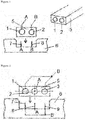
- a well-known implementation of this connection system is a two conductor cable which has a symmetrical rectangular shape, and which is used for outdoor lighting. Due to its symmetrical shape the cable can be connected in two ways which means that it is not known upfront which contact of the insulation piercing connnector is connected to which conductor in the cable ( figure 1 ). This does not have to be a problem in case of an AC application and can, for instance, be used to connect micro inverters with their AC outputs.
- Figure 1 shows such a conventional insulation piercing connection system with conductors 1 and 2, and a symmetric rectangular cross-section of cable 5 that can be used for AC application.
- the cable can be connected to insulation piercing cable connector 6 that has a shape that is complementary to the shape of cable 5.
- Connector 6 further includes cable piercing conductors 7 and 8 that pierce through the insulation cable 5 and make contact with conductors 1 and 2 of cable 5.
- polarity that can be applied is indicated by A and B.
- Incorrect electrical connection of the cable to the connector can be avoided by using a cable wherein the opposing lateral edges of a longitudinal cross-section have a different shape, such that the cable can only be connected to the connector in one way (not shown). Such cable will then not have a cross-section having a perimeter with two orthogonal axes of symmetry.
- the insulation piercing cable connection system of the invention utilises an insulation piercing cable comprising a flat cable having three or more conductors embedded in insulation material, wherein a cross-section of the insulation piercing cable has a perimeter with two orthogonal axes of symmetry, and wherein the arrangement of conductors in said cross-section has point symmetry.
- an insulation piercing cable comprising a flat cable having three or more conductors embedded in insulation material, wherein a cross-section of the insulation piercing cable has a perimeter with two orthogonal axes of symmetry, and wherein the arrangement of conductors in said cross-section has point symmetry.
- Such a cable with preferably a rectangular (optionally rounded), cross-section is easier to manufacture.
- the insulation piercing cable connection system of the invention further utilises an insulation piercing cable connector in combination with the insulation piercing cable, comprising a cavity for receiving said insulation piercing cable, wherein said cavity comprises three or more cable piercing conductors, wherein the amount of cable piercing conductors in the insulation piercing cable connector is the same as the amount of conductors in the insulation piercing cable, and wherein the insulation piercing cable connector is compatible to be electrically connected to said insulation piercing cable by piercing the insulation of said insulation piercing cable with said cable piercing conductors.
- the conductors in the insulation piercing cable connected are electrically connected (viz. are in electrical contact) to the respective conductors in the insulation piercing cable.
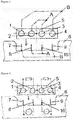
- FIG. 2 A schematic example of an embodiment of the invention is shown in figure 2 .
- This figure shows an insulation piercing cable 5 with three conductors (1, 2 and 3).
- Cable 5 is to be connected to insulation piercing cable connector 6, which has three cable piercing conductors (7, 8 and 9).
- the two outer conductors (1 and 3) in insulation piercing cable 5 are used for the same polarity in figure 2 indicated with B.
- conductors 1 and 3 will be connected to cable piercing conductors 7 and 9, which are used for the same polarity B.
- the conductors in the flat cable may all be arranged in one plane.
- a cross-section of the insulation piercing cable has two orthogonal axes of symmetry.
- the centre of point symmetry is shown in figure 2 by an asterisk.
- Two axes of symmetry are shown for the embodiment in figure 2 by dotted lines.
- the insulation piercing cable prefferably comprises four or more conductors in a plane.
- PLC Power Line Communication
- the insulation piercing cable connection system may be combined with a converter either with a DC-output or with an AC-output, preferably a converter with a DC-output.
- the amount of conductors in the insulation piercing cable is even. More preferably, the amount of the conductors used for different polarity in the insulation piercing cable is the same. Although it is possible to employ an uneven amount of conductors, this will automatically mean that there are more conductors of one polarity than there are conductors of the other polarity in the insulation piercing cable.
- the conductor cross-section (or conductor diameter) of the conductors with the polarity which is in the majority may optionally be reduced to balance the loading of the conductors for optimal use of the conductor material, although this will lead to higher manufacturing costs.
- the conductor cross-section (or conductor diameter) of each conductor in the insulation piercing cable is the same.
- the insulation piercing cable connector is compatible to be electrically connected with the insulation piercing cable of the invention.
- This means that the insulation piercing cable can be electrically connected to the connector such that the cable piercing conductors of the insulation piercing cable connector pierce through the insulation of the insulation piercing cable and each cable piercing conductor of the insulation piercing cable connector connects electrically to a different conductor in the insulation piercing cable.
- Insulation piercing cable 5 is to be connected to insulation piercing cable connector 6, which has four cable piercing conductors (7, 8, 9, and 10).
- the centre of point symmetry is shown in figure 3 by an asterisk, and two axes of symmetry are shown with dotted lines.
- each contact A and B uses two conductors in parallel.
- the two outer conductors (1 and 4) in insulation piercing cable 5 are used for the same polarity, in figure 3 indicated with B.
- conductors 1 and 4 will always be connected to cable piercing conductors 7 and 9, which are also used for polarity B.
- Conductors 2 and 3 will always be connected to cable piercing conductors 8 and 10. It does not matter in figure 3 whether conductor 1 will be connected to cable piercing conductor 7, conductor 2 to cable piercing conductor 8, conductor 3 to cable piercing conductor 10 and conductor 4 to cable piercing conductor 9, or whether conductor 1 will be connected to cable piercing conductor 9, conductor 2 to cable piercing conductor 10, conductor 3 to cable piercing conductor 8 and conductor 4 to cable piercing conductor 7.
- An additional benefit resulting from this approach is increased reliability due to the introduction of redundancy. If one contact or conductor breaks, the system will keep on operating due to the parallel connection.
- the insulation piercing cable connection system shown in figure 3 can be used both for AC as well as DC applications.
- insulation piercing cable 5 has four conductors (1, 2, 3, and 4). Cable 5 is to be connected to insulation piercing cable connector 6, which has four cable piercing conductors (7, 8, 9, and 10). The centre of point symmetry is shown in figure 4 by an asterisk, and two axes of symmetry are shown with dotted lines. The two outer conductors (1 and 4) in insulation piercing cable 5 are used for the same polarity.
- conductors 1 and 4 When insulation piercing cable 5 is connected to insulation piercing cable connector 6, conductors 1 and 4 will always be connected to cable piercing conductors 7 and 9, which are used for the same polarity (positive polarity in figure 4 ), but for different power circuits. Conductors 2 and 3 will always be connected to cable piercing conductors 8 and 10, which are used for the polarity opposite to that of the two outer cable piercing conductors 7 and 9 (negative polarity in figure 4 ), but for different power circuits.
- the configuration with the two separate power circuits, as presented in figure 4 opens the possibility to combine the power transportation function of the bus-cable with a communication function.
- Communication between the local converters and a central unit can be attractive for multiple reasons.
- Messages from the local converters can contain information about the performance and error states.
- Messages in opposite direction from a central location to the local converters can be used to reduce the power output when requested or demanded by the grid operator to maintain the power quality on the grid.
- the local converters can also be instructed to shut down completely for safety reasons, for instance in case of an accident or a fire.
- the converters can also be instructed by the grid operator to generate reactive power to maintain the power quality on the grid.
- the insulation piercing cable comprises four conductors, wherein the four conductors are used for two separate power circuits.
- Communication between a central unit and the local converters can be implemented by means of a wireless radio frequency (RF) link.
- RF radio frequency
- the alternative for RF communication is power line communication (PLC) which is sometimes used for solar power converters.
- PLC power line communication
- the drawback of conventional PLC is that it requires additional relative expensive and energy consuming electronic components.
- the multi conductor configuration presented in figure 4 provides the possibility to use PLC at a considerably lower power level thus consuming less energy which means less impact on the efficiency of the total system and less expensive electronic components necessary to implement PLC compared to a conventional PLC implementation.
- FIG. 5 shows an electronic diagram wherein two local converters are connected in opposite ways to a four-conductor bus-cable.
- the PLC communication modules are not connected between the power lines of a power circuit which is the conventional PLC implementation, but the communication module is now connected between the two separate power circuits.
- the insulation piercing cable connection system with four conductors that are used for two separate power circuits can be combined with power line communication, such that power line communication modules are connected between the two separate power circuits of the insulation piercing cable.
- the communication module is connected in the traditional way, the communication module is loaded with the low impedance of the power converters connected to the same conductors.
- the two separate power circuits are interconnected behind the central power converters (inverters) because the galvanic isolation in these converters maintain the separation between the power circuits preventing 'shorting' of the communication modules.
- Parallel connection of the output of inverters is common practice and happens for instance when using multiple micro inverters.
- the multi conductor configuration is introduced to allow a reversed connection of the convertors as described above resulting from a 'upside down' connection of the insulation piercing cable.
- the resulting reversed connection of the communication modules as visible in figure 5 does not hinder the communication because the communication modules make use of an AC signal (carrier) that is coupled by means of capacitors.
- the invention is directed to a photovoltaic system, comprising one or more photovoltaic modules connected to one or more converters via one or more insulation piercing cable connection systems according to the invention.
- the photovoltaic system is preferably integrated in a roadway surface to generate solar power.
Landscapes
- Cable Accessories (AREA)
- Life Sciences & Earth Sciences (AREA)
- Engineering & Computer Science (AREA)
- Sustainable Development (AREA)
- Sustainable Energy (AREA)
- Multi-Conductor Connections (AREA)
- Coupling Device And Connection With Printed Circuit (AREA)
Abstract
The invention is directed to an insulation piercing cable connection system, and to a photovoltaic system.
The insulation piercing cable connection system of the invention comprises an insulation piercing cable, and an insulation piercing cable connector,
wherein said insulation piercing cable comprises a flat cable having three or more conductors embedded in insulation material, wherein a cross-section of the insulation piercing cable has a perimeter with two orthogonal axes of symmetry, and wherein the arrangement of conductors in said cross-section has point symmetry, and
wherein said insulation piercing cable connector comprises a cavity for receiving said insulation piercing cable, wherein said cavity comprises three or more cable piercing conductors, wherein the amount of cable piercing conductors in the insulation piercing cable connector is the same as the amount of conductors in the insulation piercing cable, and wherein said insulation piercing cable connector is compatible to be electrically connected to said insulation piercing cable by piercing the insulation of said insulation piercing cable with said cable piercing conductors.
wherein said insulation piercing cable comprises a flat cable having three or more conductors embedded in insulation material, wherein a cross-section of the insulation piercing cable has a perimeter with two orthogonal axes of symmetry, and wherein the arrangement of conductors in said cross-section has point symmetry, and
wherein said insulation piercing cable connector comprises a cavity for receiving said insulation piercing cable, wherein said cavity comprises three or more cable piercing conductors, wherein the amount of cable piercing conductors in the insulation piercing cable connector is the same as the amount of conductors in the insulation piercing cable, and wherein said insulation piercing cable connector is compatible to be electrically connected to said insulation piercing cable by piercing the insulation of said insulation piercing cable with said cable piercing conductors.
Description
- The invention is directed to an insulation piercing cable connection system, and to a photovoltaic system.
- Photovoltaic devices are well known in the art. Such devices absorb sunlight and convert it directly into useable electrical energy. A typical photovoltaic cell is a solid-state device in which a junction is formed between adjacent layers of semiconductor materials doped with specific atoms. When light energy or photons strike the semiconductor, electrons are dislodged from the valence band. These electrons, collected by the electric field at the junction, create a voltage that can be put at work in an external circuit. The basic principles that underlie this effect are well-known and understood to those in the art.
- While solar power generation is a clean method of generating energy, there remains a lack of a cohesive integrated infrastructure that uses solar energy as a power source. In addition, some customers find the appearance of solar panels on roofs unappealing and unattractive.
- It would be desirable if solar power generation could be integrated in trafficable surfaces such as roads, parking lots, driveways, sidewalks and the like.
- In recent years, photovoltaic trafficable surfaces have emerged as a solution to increase the amount of energy harvested from the sun. A photovoltaic trafficable surface known as SolaRoad® is located in the town of Krommenie in the Netherlands. This photovoltaic trafficable surface comprises a top layer of tempered glass of about 1 cm thick with underneath crystalline silicon solar cells. The SolaRoad® system is prefabricated as a whole as 2.5 by 3.5 metre concrete modules comprising the polycrystalline silicon solar cells. These modules have to be transported to the road site and placed as such on the desired location. It is not possible to replace only part of a concrete module upon failure. This rather inflexible construction method as well as inefficient maintenance requirement results in high costs per covered surface area and produced energy unit.
- The optimal electric architecture for large scale solar power (photovoltaic) system which is subjected to irregular shadowing, such as when integrated in a road surface, makes use of local DC/DC (direct current/direct current) converters with integrated Maximum Power Point Tracking (MPPT). These local converters need to be connected to a DC-bus-cable to transport the power to a central location. Cost reduction can be obtained when this cabling system can be optimised both in terms of material cost and labour.
- The Dutch company NKF manufactured for a short period of time (around the year 2002) the OK5 micro inverter which did not use connectors for the connection of these micro inverters to the bus-cable (also referred to as trunk cable). For the bus cable a two conductor insulation piercing cable was used which was originally designed for outside lighting applications. This commonly available cable, with a symmetric rectangular cross-section could only be used because the micro inverter produces an alternating output voltage (AC, alternating current) which means that there is no strict rule that contact number one of the micro inverter has to be connected to conductor number one of the cable. It is allowed to twist the cable and swap the conductors, unlike cables that are used for direct current.
- The OK5 micro inverter makes use of "standard" Power Line Communication (PLC) over the two conductors of the cable which requires relatively expensive electronic components which in addition reduce the energy efficiency of the system due to additional dissipation losses.
- The German company Wieland Electric GmbH manufactures insulation piercing flat cable connection systems for direct current applications called Podis™ and Genesis™ which prevent incorrect connection with the cable conductors by using a flat cable wherein one lateral edge of a longitudinal cross-section of the cable has a different shape than the opposing lateral edge of the cross-section.
-
US-A-2011/0 036 386 discloses a fully integrated and self-contained alternating current photovoltaic solar panel device, which features an integral micro-inverter having a compression connector fitting for electrically connecting the utility grid. An insulating piercing connection is used to connect the alternating current output of a micro inverter onto a three wire bus-cable. Incorrect connection of the cable is prevented by using a cable wherein one lateral edge of a longitudinal cross-section of the cable has a flat shape, while the opposing lateral edge of the cross-section has a rounded shape. - The insulation piercing flat cable connection systems described in
US-A-2011/0 036 386 and those manufactured by the German manufacturer Wieland Electric GmbH prevent that the cable can be connected 'upside down'. This way it should be guaranteed that conductor number one in the cable will be connected to connection number one in the connected device. Preventing that connections can be swapped is necessary for connecting to a direct current (DC) bus. The systems used by Wieland Electric GmbH makes use of a flat cable wherein the opposing lateral edges have different shapes. The special shape of the cross-section should make it impossible to insert the cable the wrong way around. The drawback of this is that an additional twist of the cable, for instance to reduce the stress on the connection, is not allowed. The special shape with the non-rectangular cross-section is also more expensive to manufacture. - There remains a need in the art for improved insulation piercing cable connection systems. In particular, it is desirable when an insulation piercing cable connection system can be used in combination with direct current.
- Objective of the invention is to address this need in the art and/or to overcome one or more drawbacks of prior art insulation piercing cable connection systems.
- The inventors found that this objective can be met, at least in part, by providing a specially designed insulation piercing cable connection system.
- Accordingly, in a first aspect the invention is directed to an insulation piercing cable connection system, comprising an insulation piercing cable, and an insulation piercing cable connector, wherein said insulation piercing cable comprises a flat cable having three or more conductors embedded in insulation material, wherein a cross-section of the insulation piercing cable has a perimeter with two orthogonal axes of symmetry, and wherein the arrangement of conductors in said cross-section has point symmetry, and
wherein said insulation piercing cable connector comprises a cavity for receiving said insulation piercing cable, wherein said cavity comprises three or more cable piercing conductors, wherein the amount of cable piercing conductors in the insulation piercing cable connector is the same as the amount of conductors in the insulation piercing cable, and wherein said insulation piercing cable connector is compatible to be electrically connected to said insulation piercing cable by piercing the insulation of said insulation piercing cable with said cable piercing conductors. - By using a flat cable with three or more conductors that has a combination of a cross-section (perpendicular to the longitudinal axis of the cable) having a perimeter with two orthogonal axes of symmetry and a point symmetrical arrangement of conductors in said cross-section it is possible to use a cable which may also be connected 'upside down' and is relatively easy to manufacture. The insulation piercing cable connection system of the invention can be used either in combination with direct current, or with alternating current.
- The term "flat cable" as used herein is meant to refer to its commonly known meaning, i.e. a cable having a longitudinal cross-section of which the width is larger than the height. Hence, the aspect ratio (width divided by height) of the longitudinal cross-section of a flat cable is larger than 1.
- The term "insulation piercing cable" as used herein is meant to refer to a cable that is suitable for insulation piercing contacts, viz. contacts that are realised by piercing the insulation of the cable and thereby electrically contacting the conductors comprised therein to external conductors.
- The insulation piercing cable connection system of the invention may be connected to a single power circuit, such that at least the two outer cable piercing conductors in the insulation piercing cable connector are connected to each other and to a first external conductor, and an inner cable piercing conductors is connected to a second external conductor. It is also possible to have more than one inner cable piercing conductors, which may then be connected to each other and to the second external conductor.
- The insulation piercing cable connection system of the invention may also be connected to two separate power circuits, such that at least the two outer cable piercing conductors in said insulation piercing cable connector are connected to two distinct inner cable piercing conductors via two separate external conductors, and wherein conductors of the insulation piercing cable connector are connected to each other and the power circuits.
- In accordance with the invention, preferably direct current is used. This is unlike the OK5 micro inverter manufactured by NKF which makes use of alternating current (AC). A direct current bus voltage is advantageous, because an alternating current requires more complex converters electronics with an additional AC-output stage which requires more electronic components and therefore will be bigger, will have a higher manufacturing cost and lower reliability.
- Additionally, the OK5 micro inverter manufactured by NKF makes use of Power Line Communication (PLC) over the two conductors of the flat cable which lead to reduced energy conversion efficiency due to losses in the PLC coupling components and the dissipation in the PLC circuit. The invention, on the other hand, uses additional conductors in the cable where, in the case of four conductors or more, PLC can be used without the energy consuming, expensive components that are required in the case of a conventional two conductor PLC.
- In a solar power photovoltaic system, with local converters, the output of the local converters are typically connected by means of a bus cable (also called trunk cable). In such as system, the bus cable ideally operates at direct current (DC) instead of alternating current (AC). The advantages of DC over AC in this case is that the electronic circuitry in the converters can be kept simpler because an AC-output stage can be omitted. This means that less electronic components are necessary which reduces costs, size, dissipation, and increases the reliability of the converter. The use of DC instead of AC for the bus cable has additional advantages such as higher power transfer capability because the cable can be operated constantly at its maximum voltage, where in case of a sine wave AC voltage the effective (RMS) voltage is a factor 0.71 below the peak voltage.
- Connection to a DC bus means that the conductors may not be swapped in contrast with connection to an AC bus where swapping of the conductors can be allowed. To make sure that a flat insulation piercing cable system cannot be connected the wrong way around, conventionally special shapes of the cross-section of such cables have been used, which special shapes only allow to electrically connect the cable in a single manner. Such a special cross-section is relatively expensive to manufacture and it prevents the possibility to twist the cable by 180 degrees at will, for instance to reduce the stress on the connection. The insulation piercing cable used in the insulation piercing cable connection system of the invention has three or more conductors and a cross-section having a perimeter with two orthogonal axes of symmetry and a point symmetrical arrangement of conductors in said cross-section. This allows for the cable to be installed in both ways (so also upside down), and in addition guarantees that the plus and minus conductors of the DC bus system are connected the right way. The insensitivity to the installation direction of the cable makes that the cable is attractive for manufacturing and allows twisting of the cable to prevent stress on the connections.
- Communication with the converters used in a solar power (PV) system can be performed by means of wireless Radio Frequency (RF) communication. However, the specific characteristics of a solar power system integrated in a road surface hinder the operation of an RF communication link. Especially, the location of antennas close to the ground that can be wet results in undesirably high attenuation of the RF-link. The alternative for RF communication is power line communication (PLC) which is sometimes used for solar power converters. The drawback of conventional PLC is that it requires additional relatively expensive and energy consuming electronic components. The invention also provides for the possibility of using PLC but not in the traditional way over the power lines which means that considerably less energy is consumed and also less expensive components are necessary.
- In a large scale solar power photovoltaic (PV) system, the individual solar panels can be connected in series. This string of in series connected panels is then connected to a grid connected central inverter which transforms the DC current from the PV panels to the AC current of the grid. This setup works well and is efficient when there is not too much hinder from shadows both from objects as well as from clouds. However, when shadows occur frequently performance degradation will result. This performance degradation can be limited when electronic converters are added at panel level which include Maximum Power Point Tracking (MPPT). Although it is possible to connect the output of these local converters in series, the preferred option is parallel connection to a 'bus' in combination with a relatively high output voltage. A further distinction can be made between direct current (DC) and alternating current (AC). AC may have the benefit that the output of the micro inverters can be connected directly to the grid, but for a large scale solar power system, in particular when combined with a road surface, the preference is to use a DC bus voltage.
- The outputs of all the individual local converters have to be connected to the DC-bus. The stretched or lint shape of a solar power system, especially when integrated in a road surface, makes that the preferred interconnection method is the use of a bus-cable or trunk cable onto which all local converters are connected. This bus-cable with all of its connectors forms a considerable part of costs of the electric system resulting both from the material cost as well as from the labour related to preparation and installation. A considerable cost reduction can be obtained when the conventional connectors can be omitted. A known solution is the use of an insulation piercing connection system (also called insulation displacement connection), where an insulation piercing cable is pressed into a cavity of a insulation piercing cable connector which has a shape that corresponds with the shape of the cross-section of the cable. The insulation piercing connector further includes cable piercing conductors that pierce through the insulation of the cable and make contact with the conductors of the cable. A well-known implementation of this connection system is a two conductor cable which has a symmetrical rectangular shape, and which is used for outdoor lighting. Due to its symmetrical shape the cable can be connected in two ways which means that it is not known upfront which contact of the insulation piercing connnector is connected to which conductor in the cable (
figure 1 ). This does not have to be a problem in case of an AC application and can, for instance, be used to connect micro inverters with their AC outputs. -
Figure 1 shows such a conventional insulation piercing connection system withconductors cable 5 that can be used for AC application. The cable can be connected to insulation piercingcable connector 6 that has a shape that is complementary to the shape ofcable 5.Connector 6 further includescable piercing conductors insulation cable 5 and make contact withconductors cable 5. Infigure 1 , polarity that can be applied is indicated by A and B. In case of an AC application, it is irrelevant whether the cable conductor with polarity A is connected to the cable piercing conductor with polarity A or B, and whether the cable conductor with polarity B is connected to the cable piercing conductor with polarity A or B. However, in case of a DC-bus voltage it has to be guaranteed that the plus and minus connections of the local converter are connected with the plus and minus of the DC-bus cable, respectively. With reference tofigure 1 , this means that the conductor with polarity A should be connected to the cable piercing conductor with polarity A and that the conductor with polarity B should be connected to the cable piercing conductor with polarity B. Incorrect electrical connection of the cable to the connector can be avoided by using a cable wherein the opposing lateral edges of a longitudinal cross-section have a different shape, such that the cable can only be connected to the connector in one way (not shown). Such cable will then not have a cross-section having a perimeter with two orthogonal axes of symmetry. - Instead, the insulation piercing cable connection system of the invention utilises an insulation piercing cable comprising a flat cable having three or more conductors embedded in insulation material, wherein a cross-section of the insulation piercing cable has a perimeter with two orthogonal axes of symmetry, and wherein the arrangement of conductors in said cross-section has point symmetry. Such a cable with preferably a rectangular (optionally rounded), cross-section, is easier to manufacture.
- The insulation piercing cable connection system of the invention further utilises an insulation piercing cable connector in combination with the insulation piercing cable, comprising a cavity for receiving said insulation piercing cable, wherein said cavity comprises three or more cable piercing conductors, wherein the amount of cable piercing conductors in the insulation piercing cable connector is the same as the amount of conductors in the insulation piercing cable, and wherein the insulation piercing cable connector is compatible to be electrically connected to said insulation piercing cable by piercing the insulation of said insulation piercing cable with said cable piercing conductors. By piercing the insulation of the insulation piercing cable with the cable piercing conductors, the conductors in the insulation piercing cable connected are electrically connected (viz. are in electrical contact) to the respective conductors in the insulation piercing cable.
- A schematic example of an embodiment of the invention is shown in
figure 2 . This figure shows aninsulation piercing cable 5 with three conductors (1, 2 and 3).Cable 5 is to be connected to insulation piercingcable connector 6, which has three cable piercing conductors (7, 8 and 9). The two outer conductors (1 and 3) ininsulation piercing cable 5 are used for the same polarity infigure 2 indicated with B. Wheninsulation piercing cable 5 is connected to insulation piercingcable connector 6,conductors cable piercing conductors figure 2 whetherconductor 1 will be connected tocable piercing conductor 7 andconductor 3 tocable piercing conductor 9, or whetherconductor 1 will be connected tocable piercing conductor 9 andconductor 3 tocable piercing conductor 7.Conductor 2 will always be connected tocable piercing conductor 8. Hence, this configuration guarantees that contact-B of the insulation piercing cable connector is connected to contact-B on the insulation piercing cable side, and that contact-A of the insulation piercing cable connector is connected to contact-A on the insulation piercing cable side. It is not important whether the cable is inserted 'upside down' (herein also referred to as 'reversed'). The insulation piercing cable connection system shown infigure 2 can be used both for AC as well as DC applications. Inserting the cable upside down may be beneficial in certain cases to reduce the strain on the connections resulting from a twisted cable. - Preferably, the conductors in the flat cable may all be arranged in one plane. In a preferred embodiment, a cross-section of the insulation piercing cable has two orthogonal axes of symmetry. The centre of point symmetry is shown in
figure 2 by an asterisk. Two axes of symmetry are shown for the embodiment infigure 2 by dotted lines. - It is preferred for the insulation piercing cable to comprise four or more conductors in a plane. Such a configuration provides the possibility for Power Line Communication (PLC) without efficiency reduction due to dissipation in the electronic components which is the case for conventional PLC, as will be explained herein below.
- The insulation piercing cable connection system may be combined with a converter either with a DC-output or with an AC-output, preferably a converter with a DC-output.
- Preferably, the amount of conductors in the insulation piercing cable is even. More preferably, the amount of the conductors used for different polarity in the insulation piercing cable is the same. Although it is possible to employ an uneven amount of conductors, this will automatically mean that there are more conductors of one polarity than there are conductors of the other polarity in the insulation piercing cable. In such an embodiment, the conductor cross-section (or conductor diameter) of the conductors with the polarity which is in the majority may optionally be reduced to balance the loading of the conductors for optimal use of the conductor material, although this will lead to higher manufacturing costs. Preferably, the conductor cross-section (or conductor diameter) of each conductor in the insulation piercing cable is the same.
- The insulation piercing cable connector is compatible to be electrically connected with the insulation piercing cable of the invention. This means that the insulation piercing cable can be electrically connected to the connector such that the cable piercing conductors of the insulation piercing cable connector pierce through the insulation of the insulation piercing cable and each cable piercing conductor of the insulation piercing cable connector connects electrically to a different conductor in the insulation piercing cable.
- Correct connection of contacts (viz. polarities) A and B can be guaranteed with any number of conductors with a minimum of three. In case of the three conductor configuration presented in
figure 2 , the current through contact B is distributed over two conductors in the cable, compared to only one conductor in the cable for contact A. This means that the conductor cross-section of the outer conductors used for contact B can be reduced to balance the loading of the conductors if necessary. This may yield a cost benefit. Another approach is to use a cable with an additional conductor. Infigure 3 ,insulation piercing cable 5 has four conductors (1, 2, 3, and 4).Insulation piercing cable 5 is to be connected to insulation piercingcable connector 6, which has four cable piercing conductors (7, 8, 9, and 10). The centre of point symmetry is shown infigure 3 by an asterisk, and two axes of symmetry are shown with dotted lines. In this configuration, each contact A and B uses two conductors in parallel. The two outer conductors (1 and 4) ininsulation piercing cable 5 are used for the same polarity, infigure 3 indicated with B. Wheninsulation piercing cable 5 is connected to insulation piercingcable connector 6,conductors cable piercing conductors polarity B. Conductors cable piercing conductors figure 3 whetherconductor 1 will be connected tocable piercing conductor 7,conductor 2 tocable piercing conductor 8,conductor 3 tocable piercing conductor 10 andconductor 4 tocable piercing conductor 9, or whetherconductor 1 will be connected tocable piercing conductor 9,conductor 2 tocable piercing conductor 10,conductor 3 tocable piercing conductor 8 andconductor 4 tocable piercing conductor 7. An additional benefit resulting from this approach is increased reliability due to the introduction of redundancy. If one contact or conductor breaks, the system will keep on operating due to the parallel connection. The insulation piercing cable connection system shown infigure 3 can be used both for AC as well as DC applications. - When four conductors are available in the cable they can be interconnected to support only the two contacts A and B as illustrated in
figure 3 . It is, however, also possible to make a separation between two power circuits as illustrated infigure 4 . Infigure 4 ,insulation piercing cable 5 has four conductors (1, 2, 3, and 4).Cable 5 is to be connected to insulation piercingcable connector 6, which has four cable piercing conductors (7, 8, 9, and 10). The centre of point symmetry is shown infigure 4 by an asterisk, and two axes of symmetry are shown with dotted lines. The two outer conductors (1 and 4) ininsulation piercing cable 5 are used for the same polarity. Wheninsulation piercing cable 5 is connected to insulation piercingcable connector 6,conductors cable piercing conductors figure 4 ), but for different power circuits.Conductors cable piercing conductors cable piercing conductors 7 and 9 (negative polarity infigure 4 ), but for different power circuits. It does not matter infigure 4 whetherconductor 1 will be connected tocable piercing conductor 7,conductor 2 tocable piercing conductor 8,conductor 3 tocable piercing conductor 10 andconductor 4 tocable piercing conductor 9, or whetherconductor 1 will be connected tocable piercing conductor 9,conductor 2 tocable piercing conductor 10,conductor 3 tocable piercing conductor 8 andconductor 4 tocable piercing conductor 7. This configuration thus still allows the swapping of the cable (inserting upside down), when the polarity of the contacts is oriented to support this and the voltage of the two power circuits is compatible. Also this insulation piercing cable connection system shown infigure 4 can be used both for AC as well as DC applications. - The configuration with the two separate power circuits, as presented in
figure 4 , opens the possibility to combine the power transportation function of the bus-cable with a communication function. Communication between the local converters and a central unit can be attractive for multiple reasons. Messages from the local converters can contain information about the performance and error states. Messages in opposite direction from a central location to the local converters can be used to reduce the power output when requested or demanded by the grid operator to maintain the power quality on the grid. The local converters can also be instructed to shut down completely for safety reasons, for instance in case of an accident or a fire. When the bus cable is used for AC power transfer, the converters can also be instructed by the grid operator to generate reactive power to maintain the power quality on the grid. - Hence, in a special embodiment the insulation piercing cable comprises four conductors, wherein the four conductors are used for two separate power circuits.
- Communication between a central unit and the local converters can be implemented by means of a wireless radio frequency (RF) link. However, the specific characteristics of a solar power system integrated in a road surface hinder the operation of an RF communication link. Especially the location of antennas close to the ground that can be wet result in high attenuation of the RF-link. The alternative for RF communication is power line communication (PLC) which is sometimes used for solar power converters. However, the drawback of conventional PLC is that it requires additional relative expensive and energy consuming electronic components. The multi conductor configuration presented in
figure 4 , however, provides the possibility to use PLC at a considerably lower power level thus consuming less energy which means less impact on the efficiency of the total system and less expensive electronic components necessary to implement PLC compared to a conventional PLC implementation. -
Figure 5 shows an electronic diagram wherein two local converters are connected in opposite ways to a four-conductor bus-cable. As illustrated in the electronic diagram shown infigure 5 , the PLC communication modules are not connected between the power lines of a power circuit which is the conventional PLC implementation, but the communication module is now connected between the two separate power circuits. Hence, the insulation piercing cable connection system with four conductors that are used for two separate power circuits can be combined with power line communication, such that power line communication modules are connected between the two separate power circuits of the insulation piercing cable. When the communication module is connected in the traditional way, the communication module is loaded with the low impedance of the power converters connected to the same conductors. However, when the communication module is connected between the two power circuits, the loading is much lower which means that less power has to be put in the transmitter circuits to end up at a high enough signal level at the receivers for reliable communication. It is no problem that the two separate power circuits are interconnected behind the central power converters (inverters) because the galvanic isolation in these converters maintain the separation between the power circuits preventing 'shorting' of the communication modules. Parallel connection of the output of inverters is common practice and happens for instance when using multiple micro inverters. The multi conductor configuration is introduced to allow a reversed connection of the convertors as described above resulting from a 'upside down' connection of the insulation piercing cable. The resulting reversed connection of the communication modules as visible infigure 5 does not hinder the communication because the communication modules make use of an AC signal (carrier) that is coupled by means of capacitors. - In a further aspect, the invention is directed to a photovoltaic system, comprising one or more photovoltaic modules connected to one or more converters via one or more insulation piercing cable connection systems according to the invention.
- The photovoltaic system is preferably integrated in a roadway surface to generate solar power.
- The invention has been described by reference to various embodiments, compositions and methods. The skilled person understands that features of various embodiments, compositions and methods can be combined with each other.
- All references cited herein are hereby completely incorporated by reference to the same extent as if each reference were individually and specifically indicated to be incorporated by reference and were set forth in its entirety herein.
- The use of the terms "a" and "an" and "the" and similar referents in the context of describing the invention (especially in the context of the claims) are to be construed to cover both the singular and the plural, unless otherwise indicated herein or clearly contradicted by context. The terms "comprising", "having", "including" and "containing" are to be construed as open-ended terms (i.e., meaning "including, but not limited to") unless otherwise noted. Recitation of ranges of values herein are merely intended to serve as a shorthand method of referring individually to each separate value falling within the range, unless otherwise indicated herein, and each separate value is incorporated into the specification as if it were individually recited herein. The use of any and all examples, or exemplary language (e.g., "such as") provided herein, is intended merely to better illuminate the invention and does not pose a limitation on the scope of the invention unless otherwise claimed. No language in the specification should be construed as indicating any non-claimed element as essential to the practice of the invention. For the purpose of the description and of the appended claims, except where otherwise indicated, all numbers expressing amounts, quantities, percentages, and so forth, are to be understood as being modified in all instances by the term "about". Also, all ranges include any combination of the maximum and minimum points disclosed and include any intermediate ranges therein, which may or may not be specifically enumerated herein.
- Preferred embodiments of this invention are described herein. Variation of those preferred embodiments may become apparent to those of ordinary skill in the art upon reading the foregoing description. The inventors expect skilled artisans to employ such variations as appropriate, and the inventors intend for the invention to be practiced otherwise than as specifically described herein. Accordingly, this invention includes all modifications and equivalents of the subject-matter recited in the claims appended hereto as permitted by applicable law. Moreover, any combination of the above-described elements in all possible variations thereof is encompassed by the invention unless otherwise indicated herein or otherwise clearly contradicted by context. The claims are to be construed to include alternative embodiments to the extent permitted by the prior art.
- For the purpose of clarity and a concise description features are described herein as part of the same or separate embodiments, however, it will be appreciated that the scope of the invention may include embodiments having combinations of all or some of the features described.
Claims (14)
- Insulation piercing cable connection system, comprising an insulation piercing cable, and an insulation piercing cable connector, wherein said insulation piercing cable comprises a flat cable having three or more conductors embedded in insulation material, wherein a cross-section of the insulation piercing cable has a perimeter with two orthogonal axes of symmetry, and wherein the arrangement of conductors in said cross-section has point symmetry, and
wherein said insulation piercing cable connector comprises a cavity for receiving said insulation piercing cable, wherein said cavity comprises three or more cable piercing conductors, wherein the amount of cable piercing conductors in the insulation piercing cable connector is the same as the amount of conductors in the insulation piercing cable, and wherein said insulation piercing cable connector is compatible to be electrically connected to said insulation piercing cable by piercing the insulation of said insulation piercing cable with said cable piercing conductors. - Insulation piercing cable connection system according to claim 1, connected to a single power circuit, wherein at least the two outer cable piercing conductors in said insulation piercing cable connector are connected to each other and to a first external conductor, and one or more inner cable piercing conductors are connected to each other and to a second external conductor.
- Insulation piercing cable connection system according to claim 1, connected to two separate power circuits, wherein at least the two outer cable piercing conductors in said insulation piercing cable connector are connected to two distinct inner cable piercing conductors via two separate external conductors, and wherein conductors of the insulation piercing cable connector are connected to each other and the power circuits.
- Insulation piercing cable connection system according to any one of claims 1-3, wherein the perimeter of said cross-section has a rectangular shape, which rectangular shape is optionally rounded.
- Insulation piercing cable connection system according to any one of claims 1-4, wherein said insulation piercing cable comprises four or more conductors in a plane.
- Insulation piercing cable connection system according to any one of claims 1-5, wherein the amount of conductors in the insulation piercing cable is even.
- Insulation piercing cable connection system according to any one of claims 1-6, wherein said insulation piercing cable comprises a polarity indication for each of said three or more conductors comprised in said cable, and wherein the indication is such that in a cross-section of said cable, the arrangement of polarities as indicated by the polarity indication has point symmetry.
- Insulation piercing cable connection system according to any one of claims 3-7, wherein said insulation piercing cable comprises four conductors and wherein the four conductors are used for two separate power circuits.
- Insulation piercing cable connection system according to any one of claims 1-8, in combination with a converter with a DC-output.
- Insulation piercing cable connection system according to any one of claims 1-9, in combination with a converter with an AC-output.
- Insulation piercing cable connection system according to any one of claims 3-10, combined with power line communication, wherein one or more power line communication modules are connected between the said two separate power circuits of the insulation piercing cable.
- Insulation piercing cable for use in the insulation piercing cable connection system according to any one of claims 1-11, said insulation piercing cable comprising a flat cable having three or more conductors embedded in insulation material, wherein a cross-section of the insulation piercing cable has a perimeter with two orthogonal axes of symmetry, and wherein the arrangement of conductors in said cross-section has point symmetry.
- Insulation piercing cable connector for use in the insulation piercing cable connection system according to any one of claims 1-11, said insulation piercing cable connector comprising a cavity for receiving said insulation piercing cable, wherein said cavity comprises three or more cable piercing conductors, wherein the amount of cable piercing conductors in the insulation piercing cable connector is the same as the amount of conductors in the insulation piercing cable, and wherein said insulation piercing cable connector is compatible to be electrically connected to said insulation piercing cable by piercing the insulation of said insulation piercing cable with said cable piercing conductors.
- Photovoltaic system, comprising one or more photovoltaic modules connected to one or more converters via one or more insulation piercing cables connection systems according to any one of claims 1-11, one or more insulation piercing cables according to claim 12, and/or one or more insulation piercing cable connectors according to claim 13.
Priority Applications (4)
| Application Number | Priority Date | Filing Date | Title |
|---|---|---|---|
| EP17194299.8A EP3462607A1 (en) | 2017-10-02 | 2017-10-02 | Insulation piercing cable connection system |
| EP18812332.7A EP3692630B1 (en) | 2017-10-02 | 2018-10-02 | Insulation piercing cable connection system |
| PCT/NL2018/050654 WO2019070121A1 (en) | 2017-10-02 | 2018-10-02 | Insulation piercing cable connection system |
| US16/652,983 US11837992B2 (en) | 2017-10-02 | 2018-10-02 | Insulation piercing cable connection system |
Applications Claiming Priority (1)
| Application Number | Priority Date | Filing Date | Title |
|---|---|---|---|
| EP17194299.8A EP3462607A1 (en) | 2017-10-02 | 2017-10-02 | Insulation piercing cable connection system |
Publications (1)
| Publication Number | Publication Date |
|---|---|
| EP3462607A1 true EP3462607A1 (en) | 2019-04-03 |
Family
ID=60001762
Family Applications (2)
| Application Number | Title | Priority Date | Filing Date |
|---|---|---|---|
| EP17194299.8A Withdrawn EP3462607A1 (en) | 2017-10-02 | 2017-10-02 | Insulation piercing cable connection system |
| EP18812332.7A Active EP3692630B1 (en) | 2017-10-02 | 2018-10-02 | Insulation piercing cable connection system |
Family Applications After (1)
| Application Number | Title | Priority Date | Filing Date |
|---|---|---|---|
| EP18812332.7A Active EP3692630B1 (en) | 2017-10-02 | 2018-10-02 | Insulation piercing cable connection system |
Country Status (3)
| Country | Link |
|---|---|
| US (1) | US11837992B2 (en) |
| EP (2) | EP3462607A1 (en) |
| WO (1) | WO2019070121A1 (en) |
Citations (5)
| Publication number | Priority date | Publication date | Assignee | Title |
|---|---|---|---|---|
| US20100139945A1 (en) * | 2008-12-04 | 2010-06-10 | Enphase Energy, Inc. | Mounting rail and power distribution system for use in a photovoltaic system |
| US20110036386A1 (en) | 2009-08-17 | 2011-02-17 | Browder John H | Solar panel with inverter |
| EP2899867A2 (en) * | 2014-01-23 | 2015-07-29 | LG Electronics Inc. | Power conversion apparatus, photovoltaic module, and photovoltaic system including the same |
| US9225286B1 (en) * | 2013-02-25 | 2015-12-29 | Concise Design | Micro-inverter quick mount and trunk cable |
| DE102014115601B3 (en) * | 2014-10-27 | 2016-01-07 | Sma Solar Technology Ag | Combinerbox with motor overcurrent protection |
Family Cites Families (5)
| Publication number | Priority date | Publication date | Assignee | Title |
|---|---|---|---|---|
| JP3605032B2 (en) * | 2000-06-07 | 2004-12-22 | 三洋電機株式会社 | Solar cell module, solar cell module connection method, solar cell module installation method, and solar cell module ground connection method |
| US8684761B2 (en) * | 2011-06-24 | 2014-04-01 | Jacob WEAVER | Solar insulation displacement connector |
| US9553225B2 (en) * | 2012-04-11 | 2017-01-24 | Schneider Electric USA, Inc. | Tapered trunking system with distributed combiner |
| CN108695843B (en) * | 2017-03-29 | 2023-09-22 | 太阳能安吉科技有限公司 | Bypass circuits and methods of bypassing power modules in power systems |
| EP3462605A1 (en) | 2017-10-02 | 2019-04-03 | Nederlandse Organisatie voor toegepast- natuurwetenschappelijk onderzoek TNO | Photovoltaic roadway assembly |
-
2017
- 2017-10-02 EP EP17194299.8A patent/EP3462607A1/en not_active Withdrawn
-
2018
- 2018-10-02 EP EP18812332.7A patent/EP3692630B1/en active Active
- 2018-10-02 US US16/652,983 patent/US11837992B2/en active Active
- 2018-10-02 WO PCT/NL2018/050654 patent/WO2019070121A1/en not_active Ceased
Patent Citations (5)
| Publication number | Priority date | Publication date | Assignee | Title |
|---|---|---|---|---|
| US20100139945A1 (en) * | 2008-12-04 | 2010-06-10 | Enphase Energy, Inc. | Mounting rail and power distribution system for use in a photovoltaic system |
| US20110036386A1 (en) | 2009-08-17 | 2011-02-17 | Browder John H | Solar panel with inverter |
| US9225286B1 (en) * | 2013-02-25 | 2015-12-29 | Concise Design | Micro-inverter quick mount and trunk cable |
| EP2899867A2 (en) * | 2014-01-23 | 2015-07-29 | LG Electronics Inc. | Power conversion apparatus, photovoltaic module, and photovoltaic system including the same |
| DE102014115601B3 (en) * | 2014-10-27 | 2016-01-07 | Sma Solar Technology Ag | Combinerbox with motor overcurrent protection |
Also Published As
| Publication number | Publication date |
|---|---|
| US20200244218A1 (en) | 2020-07-30 |
| EP3692630A1 (en) | 2020-08-12 |
| EP3692630B1 (en) | 2023-07-05 |
| WO2019070121A8 (en) | 2020-04-23 |
| US11837992B2 (en) | 2023-12-05 |
| WO2019070121A1 (en) | 2019-04-11 |
Similar Documents
| Publication | Publication Date | Title |
|---|---|---|
| US9923515B2 (en) | Solar panels with contactless panel-to-panel connections | |
| EP1172863A2 (en) | Method of installing solar cell modules, and solar cell module | |
| US20030111103A1 (en) | Alternating current photovoltaic building block | |
| US20130168131A1 (en) | Electrical cable harness and assembly for transmitting ac electrical power | |
| CN103733474B (en) | For generating, storing and supply by the system of the electric energy of modularization DC makers generation and the correlation technique for managing the system | |
| CN102714248B (en) | Solar module arrays | |
| AU2012211436A1 (en) | Integral module power conditioning system | |
| CN101877166A (en) | Method for monitoring operating state data of solar battery package board | |
| CN107810599A (en) | Terminal for solar junction box | |
| US8294303B2 (en) | Photovoltaic grounding | |
| KR101505186B1 (en) | Photovoltaic module | |
| US9912287B2 (en) | Solar cell module and method of fabricating the same | |
| EP3692630B1 (en) | Insulation piercing cable connection system | |
| US20230027228A1 (en) | Trunk bus system | |
| JP4798956B2 (en) | Solar cell module and solar power generation apparatus using the same | |
| KR102237579B1 (en) | A solar power system with integrated windows and its installation methods | |
| KR102246803B1 (en) | One-touch connector integral photovoltaics module assembly and with integrated solar power system using them | |
| US20120312354A1 (en) | Solar module and photovoltaic array | |
| JP4578127B2 (en) | Solar cell module and solar power generation apparatus using the same | |
| GB2564123A (en) | Multi-purpose off-grid PV module design | |
| KR101506705B1 (en) | inverter integrated sollar cell pannel | |
| EP1585178A1 (en) | Solar cell module assembly, wiring system and solar power g eneration system | |
| JPH1052076A (en) | Solar power system | |
| EP2645425A1 (en) | System for distributing electrical power supplied from a solar panel array | |
| CN121358055A (en) | Solar cells, battery modules and photovoltaic systems |
Legal Events
| Date | Code | Title | Description |
|---|---|---|---|
| PUAI | Public reference made under article 153(3) epc to a published international application that has entered the european phase |
Free format text: ORIGINAL CODE: 0009012 |
|
| AK | Designated contracting states |
Kind code of ref document: A1 Designated state(s): AL AT BE BG CH CY CZ DE DK EE ES FI FR GB GR HR HU IE IS IT LI LT LU LV MC MK MT NL NO PL PT RO RS SE SI SK SM TR |
|
| AX | Request for extension of the european patent |
Extension state: BA ME |
|
| STAA | Information on the status of an ep patent application or granted ep patent |
Free format text: STATUS: THE APPLICATION IS DEEMED TO BE WITHDRAWN |
|
| 18D | Application deemed to be withdrawn |
Effective date: 20191005 |