EP3462577A1 - Modular motor structure - Google Patents
Modular motor structure Download PDFInfo
- Publication number
- EP3462577A1 EP3462577A1 EP18197136.7A EP18197136A EP3462577A1 EP 3462577 A1 EP3462577 A1 EP 3462577A1 EP 18197136 A EP18197136 A EP 18197136A EP 3462577 A1 EP3462577 A1 EP 3462577A1
- Authority
- EP
- European Patent Office
- Prior art keywords
- shaft
- motor structure
- modular motor
- joint portion
- rotor
- Prior art date
- Legal status (The legal status is an assumption and is not a legal conclusion. Google has not performed a legal analysis and makes no representation as to the accuracy of the status listed.)
- Withdrawn
Links
- 230000005291 magnetic effect Effects 0.000 claims abstract description 42
- 230000008878 coupling Effects 0.000 claims description 4
- 238000010168 coupling process Methods 0.000 claims description 4
- 238000005859 coupling reaction Methods 0.000 claims description 4
- 230000017525 heat dissipation Effects 0.000 claims description 4
- 238000006243 chemical reaction Methods 0.000 description 3
- 230000000712 assembly Effects 0.000 description 2
- 238000000429 assembly Methods 0.000 description 2
- 230000000694 effects Effects 0.000 description 2
- 230000005611 electricity Effects 0.000 description 2
- 230000013011 mating Effects 0.000 description 2
- 238000003466 welding Methods 0.000 description 2
- 230000009286 beneficial effect Effects 0.000 description 1
- 230000008859 change Effects 0.000 description 1
- 230000001419 dependent effect Effects 0.000 description 1
- 238000005323 electroforming Methods 0.000 description 1
- 230000005674 electromagnetic induction Effects 0.000 description 1
- 230000003993 interaction Effects 0.000 description 1
- 238000012986 modification Methods 0.000 description 1
- 230000004048 modification Effects 0.000 description 1
- 238000012827 research and development Methods 0.000 description 1
Images


Classifications
-
- H—ELECTRICITY
- H02—GENERATION; CONVERSION OR DISTRIBUTION OF ELECTRIC POWER
- H02K—DYNAMO-ELECTRIC MACHINES
- H02K21/00—Synchronous motors having permanent magnets; Synchronous generators having permanent magnets
- H02K21/12—Synchronous motors having permanent magnets; Synchronous generators having permanent magnets with stationary armatures and rotating magnets
- H02K21/24—Synchronous motors having permanent magnets; Synchronous generators having permanent magnets with stationary armatures and rotating magnets with magnets axially facing the armatures, e.g. hub-type cycle dynamos
-
- H—ELECTRICITY
- H02—GENERATION; CONVERSION OR DISTRIBUTION OF ELECTRIC POWER
- H02K—DYNAMO-ELECTRIC MACHINES
- H02K16/00—Machines with more than one rotor or stator
-
- F—MECHANICAL ENGINEERING; LIGHTING; HEATING; WEAPONS; BLASTING
- F02—COMBUSTION ENGINES; HOT-GAS OR COMBUSTION-PRODUCT ENGINE PLANTS
- F02B—INTERNAL-COMBUSTION PISTON ENGINES; COMBUSTION ENGINES IN GENERAL
- F02B63/00—Adaptations of engines for driving pumps, hand-held tools or electric generators; Portable combinations of engines with engine-driven devices
- F02B63/04—Adaptations of engines for driving pumps, hand-held tools or electric generators; Portable combinations of engines with engine-driven devices for electric generators
- F02B63/042—Rotating electric generators
-
- F—MECHANICAL ENGINEERING; LIGHTING; HEATING; WEAPONS; BLASTING
- F01—MACHINES OR ENGINES IN GENERAL; ENGINE PLANTS IN GENERAL; STEAM ENGINES
- F01D—NON-POSITIVE DISPLACEMENT MACHINES OR ENGINES, e.g. STEAM TURBINES
- F01D15/00—Adaptations of machines or engines for special use; Combinations of engines with devices driven thereby
- F01D15/10—Adaptations for driving, or combinations with, electric generators
-
- H—ELECTRICITY
- H02—GENERATION; CONVERSION OR DISTRIBUTION OF ELECTRIC POWER
- H02K—DYNAMO-ELECTRIC MACHINES
- H02K1/00—Details of the magnetic circuit
- H02K1/06—Details of the magnetic circuit characterised by the shape, form or construction
- H02K1/12—Stationary parts of the magnetic circuit
- H02K1/18—Means for mounting or fastening magnetic stationary parts on to, or to, the stator structures
- H02K1/182—Means for mounting or fastening magnetic stationary parts on to, or to, the stator structures to stators axially facing the rotor, i.e. with axial or conical air gap
-
- H—ELECTRICITY
- H02—GENERATION; CONVERSION OR DISTRIBUTION OF ELECTRIC POWER
- H02K—DYNAMO-ELECTRIC MACHINES
- H02K1/00—Details of the magnetic circuit
- H02K1/06—Details of the magnetic circuit characterised by the shape, form or construction
- H02K1/12—Stationary parts of the magnetic circuit
- H02K1/20—Stationary parts of the magnetic circuit with channels or ducts for flow of cooling medium
-
- H—ELECTRICITY
- H02—GENERATION; CONVERSION OR DISTRIBUTION OF ELECTRIC POWER
- H02K—DYNAMO-ELECTRIC MACHINES
- H02K1/00—Details of the magnetic circuit
- H02K1/06—Details of the magnetic circuit characterised by the shape, form or construction
- H02K1/22—Rotating parts of the magnetic circuit
- H02K1/27—Rotor cores with permanent magnets
- H02K1/2793—Rotors axially facing stators
- H02K1/2795—Rotors axially facing stators the rotor consisting of two or more circumferentially positioned magnets
-
- H—ELECTRICITY
- H02—GENERATION; CONVERSION OR DISTRIBUTION OF ELECTRIC POWER
- H02K—DYNAMO-ELECTRIC MACHINES
- H02K1/00—Details of the magnetic circuit
- H02K1/06—Details of the magnetic circuit characterised by the shape, form or construction
- H02K1/22—Rotating parts of the magnetic circuit
- H02K1/32—Rotating parts of the magnetic circuit with channels or ducts for flow of cooling medium
-
- H—ELECTRICITY
- H02—GENERATION; CONVERSION OR DISTRIBUTION OF ELECTRIC POWER
- H02K—DYNAMO-ELECTRIC MACHINES
- H02K23/00—DC commutator motors or generators having mechanical commutator; Universal AC/DC commutator motors
- H02K23/52—Motors acting also as generators, e.g. starting motors used as generators for ignition or lighting
-
- H—ELECTRICITY
- H02—GENERATION; CONVERSION OR DISTRIBUTION OF ELECTRIC POWER
- H02K—DYNAMO-ELECTRIC MACHINES
- H02K3/00—Details of windings
- H02K3/46—Fastening of windings on the stator or rotor structure
- H02K3/47—Air-gap windings, i.e. iron-free windings
-
- F—MECHANICAL ENGINEERING; LIGHTING; HEATING; WEAPONS; BLASTING
- F03—MACHINES OR ENGINES FOR LIQUIDS; WIND, SPRING, OR WEIGHT MOTORS; PRODUCING MECHANICAL POWER OR A REACTIVE PROPULSIVE THRUST, NOT OTHERWISE PROVIDED FOR
- F03D—WIND MOTORS
- F03D9/00—Adaptations of wind motors for special use; Combinations of wind motors with apparatus driven thereby; Wind motors specially adapted for installation in particular locations
- F03D9/20—Wind motors characterised by the driven apparatus
- F03D9/25—Wind motors characterised by the driven apparatus the apparatus being an electrical generator
-
- F—MECHANICAL ENGINEERING; LIGHTING; HEATING; WEAPONS; BLASTING
- F05—INDEXING SCHEMES RELATING TO ENGINES OR PUMPS IN VARIOUS SUBCLASSES OF CLASSES F01-F04
- F05B—INDEXING SCHEME RELATING TO WIND, SPRING, WEIGHT, INERTIA OR LIKE MOTORS, TO MACHINES OR ENGINES FOR LIQUIDS COVERED BY SUBCLASSES F03B, F03D AND F03G
- F05B2240/00—Components
- F05B2240/10—Stators
- F05B2240/14—Casings, housings, nacelles, gondels or the like, protecting or supporting assemblies there within
-
- F—MECHANICAL ENGINEERING; LIGHTING; HEATING; WEAPONS; BLASTING
- F05—INDEXING SCHEMES RELATING TO ENGINES OR PUMPS IN VARIOUS SUBCLASSES OF CLASSES F01-F04
- F05D—INDEXING SCHEME FOR ASPECTS RELATING TO NON-POSITIVE-DISPLACEMENT MACHINES OR ENGINES, GAS-TURBINES OR JET-PROPULSION PLANTS
- F05D2230/00—Manufacture
- F05D2230/50—Building or constructing in particular ways
- F05D2230/51—Building or constructing in particular ways in a modular way, e.g. using several identical or complementary parts or features
-
- F—MECHANICAL ENGINEERING; LIGHTING; HEATING; WEAPONS; BLASTING
- F05—INDEXING SCHEMES RELATING TO ENGINES OR PUMPS IN VARIOUS SUBCLASSES OF CLASSES F01-F04
- F05D—INDEXING SCHEME FOR ASPECTS RELATING TO NON-POSITIVE-DISPLACEMENT MACHINES OR ENGINES, GAS-TURBINES OR JET-PROPULSION PLANTS
- F05D2240/00—Components
- F05D2240/40—Use of a multiplicity of similar components
-
- H—ELECTRICITY
- H02—GENERATION; CONVERSION OR DISTRIBUTION OF ELECTRIC POWER
- H02K—DYNAMO-ELECTRIC MACHINES
- H02K2213/00—Specific aspects, not otherwise provided for and not covered by codes H02K2201/00 - H02K2211/00
- H02K2213/12—Machines characterised by the modularity of some components
Definitions
- the present invention relates to a modular energy conversion device, and more particularly to a modular motor structure.
- Generators and motors are commonly used energy conversion devices.
- the principle of a generator is similar to that of a motor. The difference between the two is that the direction of energy conversion is different.
- the generator may use various powers (such as hydraulic power, wind power, etc.) to make the rotor rotate relative to the stator.
- the coil Through the change of the magnetic field, the coil generates an induced current due to the electromagnetic induction effect; or, after generating electricity (for example, using solar energy) to generate DC power, the DC motor is started to drive the generator to generate electricity.
- An external power source supplies power to the motor to energize the rotor or the coil of the stator, such that the rotor can be rotated relative to the stator due to the magnetic interaction.
- Taiwan Patent Early Publication No. 201715823 discloses a "Large Rated Power Dynamo", which comprises an upper end cover, a lower end cover, and a plurality of rotor assemblies stacked between the upper end cover and the lower end cover.
- a stator assembly is provided between every adjacent two of the rotor assemblies.
- Between the upper end cover and the rotator assembly adjacent to the upper end cover is also provided with a stator assembly.
- Between the lower end cover and the rotator assembly adjacent to the lower end cover is also provided with a stator assembly.
- Taiwan Patent Publication No. 1274460 discloses a "tandem motor accelerator", which mainly includes two motors connected in series and disposed in a casing assembly, an outer annular gear, a planetary arm, and a planetary gear set disposed in the planetary arm.
- a sun gear is disposed in the planetary arm.
- An output shaft is disposed in the sun gear.
- the sun gear meshes with the planetary gear.
- the two motors respectively drive the planetary arm and the annular gear of the planetary gear set, and then output their rotational power through the output shaft of the sun gear.
- the modular motor structure comprises a plurality of modules arranged along an axial direction.
- the modules each comprise a stator and a rotor.
- the stator comprises at least one housing member and a plurality of coils.
- the housing member includes a pair of side walls and a connecting wall.
- the connecting wall is connected to the pair of side walls.
- a rotation space is defined between the pair of side walls and the connecting wall.
- the housing member has a first circulation opening communicating with the rotation space and extending along the axial direction.
- the pair of side walls are provided with the coils, respectively.
- the rotor includes at least one disc and a plurality of magnetic members.
- the disc includes a shaft joint portion and a magnetic member mounting portion.
- the magnetic member mounting portion surrounds the shaft joint portion and corresponds to the pair of side walls.
- the disc further has at least one second circulation opening defined between the magnetic member mounting portion and the shaft joint portion and extending along the axial direction.
- the magnetic members are spaced apart from each other and disposed in the magnetic member mounting portion.
- the magnetic member mounting portion is provided with a plurality of spaced mounting grooves for mounting the magnetic members respectively.
- the mounting grooves and the magnetic members each have an arc shape.
- the shaft joint portion has a shaft hole for connecting a rotating shaft member.
- the rotating shaft member includes at least one shaft.
- the shaft is inserted into the shaft hole of the shaft joint portion.
- the rotating shaft member includes a plurality of shafts. Every adjacent two of the shafts are connected in series by a coupling.
- the shaft joint portion has a plurality of engaging portions adjacent to the shaft hole for engaging the shaft.
- the shaft joint portion has at least one screw hole communicating with the shaft hole.
- the screw hole is locked by a screw to tighten the shaft.
- the rotor includes a plurality of discs that are spaced apart from each other.
- the modules each further includes a fixing seat for the stator to be fixedly mounted.
- the modules are arranged side by side and abut against each other through the fixing seat.
- the second circulation opening is plural and spaced apparat from each other and arranged around the shaft joint portion.
- the present invention can preferably achieve following effects:
- the stator and the rotor have the first circulation opening and the second circulation opening that extend axially and communicate with each other.
- the weight of the rotor can be reduced so that the rotor can be driven easily, and on the other hand, air can flow among the first circulation opening, and the second circulation opening and the rotation space for heat dissipation to improve the working efficiency.
- Each module is modularized with independent functions, which is convenient to adjust the quantity and the configuration according to different power consumption or different output requirements to enhance the flexibility of product use.
- the housing member includes a pair of side walls. Each of the side walls is provided with the coils, which is beneficial for increasing the amount of magnetic force generated.
- the modules can be driven by the same shaft or a plurality of shafts that are connected in series by the coupling.
- the shaft joint portion is provided with the screw and the engaging portions, so that the shaft can form an exact interlocking relationship with the shaft joint portion.
- a modular motor structure (100) in accordance with a first embodiment of the present invention comprises a plurality of modules (10) arranged along an axial direction (L).
- Each module (10) comprises a stator (1) and a rotor (2).
- the stator (1) comprises a housing member (11) and a plurality of coils (12).
- each module (10) further includes a fixing seat (3) for the stator (1) to be fixedly mounted by means of inlaying, welding, locking, or the like.
- the modules (10) are arranged side by side and abut against each other through the fixing seat (3).
- the housing member (11) may be integrally formed or may include a plurality of housings (110) that are connected to each other by means of inlaying, welding, locking, or the like.
- Each housing (110) includes a pair of side walls (111) and a connecting wall (112).
- the pair of side walls (111) are provided with the coils (12), respectively.
- the coils (12) may be, for example, printed circuits or circuit wiring coils formed by electroforming to reduce the occupied area, or the coils (12) may adopt enamelled coils.
- the coils (12) are collectively or respectively connected to a charging circuit, a power supply circuit or a power source, etc., and can be adjusted according to different requirements for charging, supplying power or inputting power.
- the connecting wall (112) is connected to the pair of side walls (111).
- a rotation space (113) is defined between the pair of side walls (111) and the connecting wall (112).
- the housing member (11) has a first circulation opening (114) communicating with the rotation space (113) and extending along the axial direction (L).
- the rotor (2) comprises a disc (21) and a plurality of magnetic members (22).
- the disc (21) comprises a shaft joint portion (211) and a magnetic member mounting portion (212).
- the shaft joint portion (211) has a shaft hole (2111) for receiving a shaft (41) of a rotating shaft member (4).
- the shaft joint portion (211) has a plurality of engaging portions (2112) adjacent to the shaft hole (2111) for engaging the shaft (41) (for example, a key and a key groove).
- the shaft joint portion (211) has a plurality of screw holes (2113) communicating with the shaft hole (2111). Each screw hole (2113) is locked by a screw (2114) to further tighten the shaft (41).
- the magnetic member mounting portion (212) surrounds the shaft joint portion (211) and corresponds to the pair of side walls (111).
- the disc (21) further has a plurality of second circulation openings (23) defined between the magnetic member mounting portion (212) and the shaft joint portion (211) and extending along the axial direction (L).
- the second circulation openings (23) each have an arc shape and are spaced apart from each other and arranged around the shaft joint portion (211).
- the magnetic members (22) are spaced apart from each other and disposed in the magnetic member mounting portion (212).
- the magnetic member mounting portion (212) is provided with a plurality of spaced mounting grooves (2121) for mounting the magnetic members (22) by means of inlaying, bonding, or the like.
- the mounting grooves (2121) and the magnetic members (22) each have an arc shape.
- the mounting grooves (2121) and the magnetic members (22) have matching features (2210) (220) for mating with each other.
- the mating features (2210) (220) may be, for example, ribs and grooves extending along the axial direction (L).
- the coils (12) of the stator (1) when the coils (12) of the stator (1) are energized, the coils (12) will drive the rotor (2) to rotate due to the magnetic effect of the current interacting with the magnetic members (22) of the rotor (2). Because the stator (1) and the rotor (2) have the first circulation opening (114) and the second circulation openings (23) extending along the axial direction (L) and communicating with each other, allowing air to flow among the first circulation opening (114), the second circulation openings (23) and the rotation space (113) for heat dissipation, the heat generated by the coils (12) due to energization can also be dissipated by the flow of air to improve the working efficiency.
- a second embodiment of the present invention is substantially similar to the first embodiment, including a plurality of modules (10) arranged along an axial direction (L).
- the main difference is that the rotating shaft member (4A) includes a plurality of shafts (41A). Every adjacent two of the shafts (41A) are connected in series by a coupling (42A), thereby achieving the purpose of jointly interlinking the plurality of modules (10).
- a third embodiment of the present invention is substantially similar to the first embodiment.
- the main difference from the first embodiment is that the rotor (2B) may include a plurality of discs (21B) that are spaced apart from each other and arranged along the axial direction (L).
- the discs (21B) share the same shaft joint portion (211B); correspondingly, the stator may include a plurality of housings that are axially spaced.
Landscapes
- Engineering & Computer Science (AREA)
- Power Engineering (AREA)
- Mechanical Engineering (AREA)
- General Engineering & Computer Science (AREA)
- Chemical & Material Sciences (AREA)
- Combustion & Propulsion (AREA)
- Motor Or Generator Cooling System (AREA)
- Connection Of Motors, Electrical Generators, Mechanical Devices, And The Like (AREA)
- Permanent Magnet Type Synchronous Machine (AREA)
- Motor Or Generator Frames (AREA)
- Synchronous Machinery (AREA)
Abstract
A The modular motor structure (100) includes a plurality of modules (10) arranged along an axial direction (L). The modules (10) each include a stator (1) and a rotor (2). The stator (1) includes at least one housing member (11) and a plurality of coils (12). The housing member (11) defines a rotation space (113) therein. The rotor (2) includes at least one disc (21) and a plurality of magnetic members (22). The disc (21) includes a shaft joint portion (211) and a magnetic member mounting portion (212). The magnetic members (22) are spaced apart from each other and disposed in the magnetic member mounting portion (212).
Description
- The present invention relates to a modular energy conversion device, and more particularly to a modular motor structure.
- Generators and motors (or electrical machines) are commonly used energy conversion devices. The principle of a generator is similar to that of a motor. The difference between the two is that the direction of energy conversion is different. The generator may use various powers (such as hydraulic power, wind power, etc.) to make the rotor rotate relative to the stator. Through the change of the magnetic field, the coil generates an induced current due to the electromagnetic induction effect; or, after generating electricity (for example, using solar energy) to generate DC power, the DC motor is started to drive the generator to generate electricity. An external power source supplies power to the motor to energize the rotor or the coil of the stator, such that the rotor can be rotated relative to the stator due to the magnetic interaction.
- Taiwan Patent Early Publication No.
201715823 - Taiwan Patent Publication No.
1274460 - However, how to make the motor adjust the quantity and the configuration according to different output requirements to enhance the flexibility of product use and improve the working efficiency of the product is still a subject of research and development.
- The object of the invention is achieved by the subject-matter of the independent claim. Advantageous embodiments are disclosed by the dependent claims.
- In order to improve the flexibility and working efficiency of product use, a modular motor structure according to one example of the present invention is provided. The modular motor structure comprises a plurality of modules arranged along an axial direction. The modules each comprise a stator and a rotor. The stator comprises at least one housing member and a plurality of coils. The housing member includes a pair of side walls and a connecting wall. The connecting wall is connected to the pair of side walls. A rotation space is defined between the pair of side walls and the connecting wall. The housing member has a first circulation opening communicating with the rotation space and extending along the axial direction. The pair of side walls are provided with the coils, respectively. The rotor includes at least one disc and a plurality of magnetic members. The disc includes a shaft joint portion and a magnetic member mounting portion. The magnetic member mounting portion surrounds the shaft joint portion and corresponds to the pair of side walls. The disc further has at least one second circulation opening defined between the magnetic member mounting portion and the shaft joint portion and extending along the axial direction. The magnetic members are spaced apart from each other and disposed in the magnetic member mounting portion. When the coils of the stator are energized, the coils drive the magnetic members of the rotor to rotate due to a magnetic effect of current interacting with the magnetic members of the rotor, and air flows among the first circulation opening, the second circulation opening and the rotation space for heat dissipation.
- For example, the magnetic member mounting portion is provided with a plurality of spaced mounting grooves for mounting the magnetic members respectively.
- For example, the mounting grooves and the magnetic members each have an arc shape.
- For example, the shaft joint portion has a shaft hole for connecting a rotating shaft member. The rotating shaft member includes at least one shaft. The shaft is inserted into the shaft hole of the shaft joint portion. Alternatively, the rotating shaft member includes a plurality of shafts. Every adjacent two of the shafts are connected in series by a coupling.
- For example, the shaft joint portion has a plurality of engaging portions adjacent to the shaft hole for engaging the shaft.
- For example, the shaft joint portion has at least one screw hole communicating with the shaft hole. The screw hole is locked by a screw to tighten the shaft.
- For example, the rotor includes a plurality of discs that are spaced apart from each other.
- For example, the modules each further includes a fixing seat for the stator to be fixedly mounted. The modules are arranged side by side and abut against each other through the fixing seat.
- For example, the second circulation opening is plural and spaced apparat from each other and arranged around the shaft joint portion.
- According to the above technical features, the present invention can preferably achieve following effects:
- 1. The stator and the rotor have the first circulation opening and the second circulation opening that extend axially and communicate with each other. On the one hand, the weight of the rotor can be reduced so that the rotor can be driven easily, and on the other hand, air can flow among the first circulation opening, and the second circulation opening and the rotation space for heat dissipation to improve the working efficiency.
- 2. Each module is modularized with independent functions, which is convenient to adjust the quantity and the configuration according to different power consumption or different output requirements to enhance the flexibility of product use.
- 3. The housing member includes a pair of side walls. Each of the side walls is provided with the coils, which is beneficial for increasing the amount of magnetic force generated.
- 4. The modules can be driven by the same shaft or a plurality of shafts that are connected in series by the coupling.
- 5. The shaft joint portion is provided with the screw and the engaging portions, so that the shaft can form an exact interlocking relationship with the shaft joint portion.
-
-
FIG. 1 is a perspective view in accordance with a first embodiment of the present invention; -
FIG. 2 is an exploded view in accordance with the first embodiment of the present invention; -
FIG. 3 is a sectional view in accordance with the first embodiment of the present invention; -
FIG. 4 is a planar view in accordance with a second embodiment of the present invention; and -
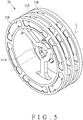
FIG. 5 is a perspective view of the rotor in accordance with a third embodiment of the present invention. - In combination with the above technical features, the main functions of the modular motor structure of the present invention will now be clearly shown in the following embodiments, by way of example only, with reference to the accompanying drawings.
- Referring to
FIG. 1 , a modular motor structure (100) in accordance with a first embodiment of the present invention comprises a plurality of modules (10) arranged along an axial direction (L). Each module (10) comprises a stator (1) and a rotor (2). The stator (1) comprises a housing member (11) and a plurality of coils (12). In this embodiment, each module (10) further includes a fixing seat (3) for the stator (1) to be fixedly mounted by means of inlaying, welding, locking, or the like. The modules (10) are arranged side by side and abut against each other through the fixing seat (3). - Referring to
FIG. 2 , in conjunction withFIG. 1 , the housing member (11) may be integrally formed or may include a plurality of housings (110) that are connected to each other by means of inlaying, welding, locking, or the like. Each housing (110) includes a pair of side walls (111) and a connecting wall (112). The pair of side walls (111) are provided with the coils (12), respectively. The coils (12) may be, for example, printed circuits or circuit wiring coils formed by electroforming to reduce the occupied area, or the coils (12) may adopt enamelled coils. The coils (12) are collectively or respectively connected to a charging circuit, a power supply circuit or a power source, etc., and can be adjusted according to different requirements for charging, supplying power or inputting power. The connecting wall (112) is connected to the pair of side walls (111). A rotation space (113) is defined between the pair of side walls (111) and the connecting wall (112). The housing member (11) has a first circulation opening (114) communicating with the rotation space (113) and extending along the axial direction (L). - Referring to
FIG. 2 , in conjunction withFIG. 1 , the rotor (2) comprises a disc (21) and a plurality of magnetic members (22). The disc (21) comprises a shaft joint portion (211) and a magnetic member mounting portion (212). The shaft joint portion (211) has a shaft hole (2111) for receiving a shaft (41) of a rotating shaft member (4). Preferably, the shaft joint portion (211) has a plurality of engaging portions (2112) adjacent to the shaft hole (2111) for engaging the shaft (41) (for example, a key and a key groove). Preferably, the shaft joint portion (211) has a plurality of screw holes (2113) communicating with the shaft hole (2111). Each screw hole (2113) is locked by a screw (2114) to further tighten the shaft (41). - Referring to
FIG. 2 , in conjunction withFIG. 1 , the magnetic member mounting portion (212) surrounds the shaft joint portion (211) and corresponds to the pair of side walls (111). The disc (21) further has a plurality of second circulation openings (23) defined between the magnetic member mounting portion (212) and the shaft joint portion (211) and extending along the axial direction (L). In this embodiment, the second circulation openings (23) each have an arc shape and are spaced apart from each other and arranged around the shaft joint portion (211). The magnetic members (22) are spaced apart from each other and disposed in the magnetic member mounting portion (212). In detail, the magnetic member mounting portion (212) is provided with a plurality of spaced mounting grooves (2121) for mounting the magnetic members (22) by means of inlaying, bonding, or the like. In this embodiment, the mounting grooves (2121) and the magnetic members (22) each have an arc shape. The mounting grooves (2121) and the magnetic members (22) have matching features (2210) (220) for mating with each other. The mating features (2210) (220) may be, for example, ribs and grooves extending along the axial direction (L). - Referring to
FIG. 3 , when the coils (12) of the stator (1) are energized, the coils (12) will drive the rotor (2) to rotate due to the magnetic effect of the current interacting with the magnetic members (22) of the rotor (2). Because the stator (1) and the rotor (2) have the first circulation opening (114) and the second circulation openings (23) extending along the axial direction (L) and communicating with each other, allowing air to flow among the first circulation opening (114), the second circulation openings (23) and the rotation space (113) for heat dissipation, the heat generated by the coils (12) due to energization can also be dissipated by the flow of air to improve the working efficiency. - Referring to
FIG. 4 , a second embodiment of the present invention is substantially similar to the first embodiment, including a plurality of modules (10) arranged along an axial direction (L). The main difference is that the rotating shaft member (4A) includes a plurality of shafts (41A). Every adjacent two of the shafts (41A) are connected in series by a coupling (42A), thereby achieving the purpose of jointly interlinking the plurality of modules (10). - Referring to
FIG. 5 , a third embodiment of the present invention is substantially similar to the first embodiment. The main difference from the first embodiment is that the rotor (2B) may include a plurality of discs (21B) that are spaced apart from each other and arranged along the axial direction (L). The discs (21B) share the same shaft joint portion (211B); correspondingly, the stator may include a plurality of housings that are axially spaced. - Although particular embodiments of the present invention have been described in detail for purposes of illustration, various modifications and enhancements may be made without departing from the spirit and scope of the present invention. Accordingly, the present invention is not to be limited except as by the appended claims.
Claims (10)
- A modular motor structure (100), comprising:a plurality of modules (10), arranged along an axial direction (L), the modules (10) each comprising a stator (1) and a rotor (2), the stator (1) comprising at least one housing member (11) and a plurality of coils (12), the rotor (2) including at least one disc (21) and a plurality of magnetic members (22), the disc (21) including a shaft joint portion (211) and a magnetic member mounting portion (212),characterized inthat the housing member (11) includes a pair of side walls (111) and a connecting wall (112), the connecting wall (112) being connected to the pair of side walls (111), a rotation space (113) being defined between the pair of side walls (111) and the connecting wall (112), the housing member (11) having a first circulation opening (114) communicating with the rotation space (113) and extending along the axial direction (L), the pair of side walls (111) being provided with the coils (12) respectively; the magnetic member mounting portion (212) surrounding the shaft joint portion (211) and corresponding to the pair of side walls (111), the disc (21) further having at least one second circulation opening (23) defined between the magnetic member mounting portion (212) and the shaft joint portion (211) and extending along the axial direction (L), the magnetic members (22) being spaced apart from each other and disposed in the magnetic member mounting portion (212); wherein when the coils (12) of the stator (1) are energized, the coils (12) drive the rotor (2) to rotate due to a magnetic effect of current interacting with the magnetic members (22) of the rotor (2), and air flows among the first circulation opening (114), the second circulation opening (23) and the rotation space (113) for heat dissipation.
- The modular motor structure (100) as claimed in claim 1, wherein the magnetic member mounting portion (212) is provided with a plurality of spaced mounting grooves (2121) for mounting the magnetic members (22) respectively.
- The modular motor structure (100) as claimed in claim 2, wherein the mounting grooves (2121) and the magnetic members (22) each have an arc shape.
- The modular motor structure (100) as claimed in claim 1, wherein the shaft joint portion (211) has a shaft hole (2111), the modular motor structure (100) further comprises a rotating shaft member (4), the rotating shaft member (4) includes at least one shaft (41), and the shaft (41) is inserted into the shaft hole (2111) of the shaft joint portion (211).
- The modular motor structure (100) as claimed in claim 4, wherein the rotating shaft member (4A) includes a plurality of shafts (41A), and every adjacent two of the shafts (41A) are connected in series by a coupling (42A).
- The modular motor structure (100) as claimed in claim 4, wherein the shaft joint portion (211) has a plurality of engaging portions (2112) adjacent to the shaft hole (2111) for engaging the shaft (41).
- The modular motor structure (100) as claimed in claim 4, wherein the shaft joint portion (211) has at least one screw hole (2113) communicating with the shaft hole (2111), and the screw hole (2113) is locked by a screw (2114) to tighten the shaft (41).
- The modular motor structure (100) as claimed in claim 1, wherein the rotor (2B) includes a plurality of discs (21B) that are spaced apart from each other.
- The modular motor structure (100) as claimed in claim 1, wherein the modules (10) each further includes a fixing seat (3) for the stator (1) to be fixedly mounted, and the modules (10) are arranged side by side and abut against each other through the fixing seat (3).
- The modular motor structure (100) as claimed in claim 1, wherein the second circulation opening (23) is plural and spaced apparat from each other and arranged around the shaft joint portion (211).
Applications Claiming Priority (1)
| Application Number | Priority Date | Filing Date | Title |
|---|---|---|---|
| TW106133624A TWI658682B (en) | 2017-09-29 | 2017-09-29 | Modular power generation unit |
Publications (1)
| Publication Number | Publication Date |
|---|---|
| EP3462577A1 true EP3462577A1 (en) | 2019-04-03 |
Family
ID=65479763
Family Applications (3)
| Application Number | Title | Priority Date | Filing Date |
|---|---|---|---|
| EP18197152.4A Withdrawn EP3462578A1 (en) | 2017-09-29 | 2018-09-27 | Modular power generation device |
| EP18197136.7A Withdrawn EP3462577A1 (en) | 2017-09-29 | 2018-09-27 | Modular motor structure |
| EP18197228.2A Withdrawn EP3462579A1 (en) | 2017-09-29 | 2018-09-27 | Modular power generation device |
Family Applications Before (1)
| Application Number | Title | Priority Date | Filing Date |
|---|---|---|---|
| EP18197152.4A Withdrawn EP3462578A1 (en) | 2017-09-29 | 2018-09-27 | Modular power generation device |
Family Applications After (1)
| Application Number | Title | Priority Date | Filing Date |
|---|---|---|---|
| EP18197228.2A Withdrawn EP3462579A1 (en) | 2017-09-29 | 2018-09-27 | Modular power generation device |
Country Status (6)
| Country | Link |
|---|---|
| US (1) | US20190101053A1 (en) |
| EP (3) | EP3462578A1 (en) |
| JP (1) | JP2019068727A (en) |
| CN (1) | CN109586533A (en) |
| CA (1) | CA3018383A1 (en) |
| TW (1) | TWI658682B (en) |
Families Citing this family (2)
| Publication number | Priority date | Publication date | Assignee | Title |
|---|---|---|---|---|
| DE102019132756A1 (en) * | 2019-12-03 | 2021-06-10 | Schaeffler Technologies AG & Co. KG | ELECTRIC DRIVE SYSTEM |
| CN118532332B (en) * | 2024-05-27 | 2025-02-14 | 武汉理工大学 | A self-priming multistage centrifugal pump with an integrated disc motor |
Citations (7)
| Publication number | Priority date | Publication date | Assignee | Title |
|---|---|---|---|---|
| WO1986002789A1 (en) * | 1984-11-01 | 1986-05-09 | Fanuc Ltd | Method of manufacturing windings for synchronous motors |
| WO1998026495A2 (en) * | 1996-12-11 | 1998-06-18 | Advanced Technologies International, Ltd. | Motor/generator |
| US5962942A (en) * | 1996-05-31 | 1999-10-05 | The Turbo Genset Company Limited | Rotary electrical machines |
| TWI274460B (en) | 2005-02-25 | 2007-02-21 | Nat Huwei Institue Of Technolo | Series type motor accelerator |
| US20070040465A1 (en) * | 2004-09-02 | 2007-02-22 | Nazar Al-Khayat | Alternator assembly |
| EP2479876A2 (en) * | 2009-09-18 | 2012-07-25 | Bang, Deok Je | Direct-drive electric equipment |
| TW201715823A (en) | 2015-10-27 | 2017-05-01 | 彪 羅 | Large rated power dynamo |
Family Cites Families (13)
| Publication number | Priority date | Publication date | Assignee | Title |
|---|---|---|---|---|
| US3992641A (en) * | 1974-11-22 | 1976-11-16 | Westinghouse Electric Corporation | Polyphase disc reluctance motor |
| US4371801A (en) * | 1978-10-11 | 1983-02-01 | General Electric Company | Method and apparatus for output regulation of multiple disk permanent magnet machines |
| DE602005018605D1 (en) * | 2005-04-22 | 2010-02-11 | Infranor Holding S A | System for attaching permanent magnets |
| JP2009072009A (en) * | 2007-09-14 | 2009-04-02 | Shin Etsu Chem Co Ltd | Permanent magnet rotating machine |
| JP2010141991A (en) * | 2008-12-10 | 2010-06-24 | Jtekt Corp | Rotating motor |
| TWM397104U (en) * | 2009-11-23 | 2011-01-21 | Chia-Wei Lin | New coil module of generator |
| TWM393106U (en) * | 2010-06-24 | 2010-11-21 | Jian-Jie Huang | High performance generator tray which without a iron core |
| TWM416933U (en) * | 2011-06-30 | 2011-11-21 | Rui-Li Jiang | Axial flux permanent magnet ON Generator structure |
| EP2828962B1 (en) * | 2012-03-20 | 2021-05-12 | Linear Labs, Inc. | An improved dc electric motor/generator with enhanced permanent magnet flux densities |
| JP6034160B2 (en) * | 2012-11-29 | 2016-11-30 | 富士重工業株式会社 | Power generation unit |
| TW201439449A (en) * | 2013-04-03 | 2014-10-16 | Direction Technology Co Ltd | Electricity-generating feedback braking system |
| CN203883618U (en) * | 2014-05-15 | 2014-10-15 | 镇江东方康驰电机制造有限公司 | Iron-core-free axial magnetic field permanent magnetism generator heat radiation structure |
| CN205086698U (en) * | 2015-11-13 | 2016-03-16 | 领翼新能源科技(上海)有限公司 | Ampere force brake equipment reaches energy recuperation system including it |
-
2017
- 2017-09-29 TW TW106133624A patent/TWI658682B/en active
-
2018
- 2018-09-19 US US16/135,203 patent/US20190101053A1/en not_active Abandoned
- 2018-09-20 CN CN201811101925.XA patent/CN109586533A/en active Pending
- 2018-09-24 CA CA3018383A patent/CA3018383A1/en not_active Abandoned
- 2018-09-25 JP JP2018178475A patent/JP2019068727A/en active Pending
- 2018-09-27 EP EP18197152.4A patent/EP3462578A1/en not_active Withdrawn
- 2018-09-27 EP EP18197136.7A patent/EP3462577A1/en not_active Withdrawn
- 2018-09-27 EP EP18197228.2A patent/EP3462579A1/en not_active Withdrawn
Patent Citations (7)
| Publication number | Priority date | Publication date | Assignee | Title |
|---|---|---|---|---|
| WO1986002789A1 (en) * | 1984-11-01 | 1986-05-09 | Fanuc Ltd | Method of manufacturing windings for synchronous motors |
| US5962942A (en) * | 1996-05-31 | 1999-10-05 | The Turbo Genset Company Limited | Rotary electrical machines |
| WO1998026495A2 (en) * | 1996-12-11 | 1998-06-18 | Advanced Technologies International, Ltd. | Motor/generator |
| US20070040465A1 (en) * | 2004-09-02 | 2007-02-22 | Nazar Al-Khayat | Alternator assembly |
| TWI274460B (en) | 2005-02-25 | 2007-02-21 | Nat Huwei Institue Of Technolo | Series type motor accelerator |
| EP2479876A2 (en) * | 2009-09-18 | 2012-07-25 | Bang, Deok Je | Direct-drive electric equipment |
| TW201715823A (en) | 2015-10-27 | 2017-05-01 | 彪 羅 | Large rated power dynamo |
Also Published As
| Publication number | Publication date |
|---|---|
| CA3018383A1 (en) | 2019-03-29 |
| EP3462579A1 (en) | 2019-04-03 |
| TW201916546A (en) | 2019-04-16 |
| JP2019068727A (en) | 2019-04-25 |
| CN109586533A (en) | 2019-04-05 |
| EP3462578A1 (en) | 2019-04-03 |
| TWI658682B (en) | 2019-05-01 |
| US20190101053A1 (en) | 2019-04-04 |
Similar Documents
| Publication | Publication Date | Title |
|---|---|---|
| EP1968185B1 (en) | Methods and systems for operating direct current motors | |
| US10566856B2 (en) | AC permanent magnet motor | |
| RU2566590C2 (en) | Power supply for devices supported by aircraft engine rotor | |
| CN101208853A (en) | Motor and manufacturing method | |
| US20140021279A1 (en) | Heavy duty mill | |
| US10298104B2 (en) | Electrical motor and electrical generator device | |
| US7965007B2 (en) | Three dimensional motor generator system | |
| JP2020510386A (en) | Magnetic propulsion and power generation systems | |
| EP3462577A1 (en) | Modular motor structure | |
| KR20050092742A (en) | Electric machine for the propulsion drive of a submarine of a synchronous machine excited by a permanent magnet | |
| KR20220125449A (en) | Motor With Self-generation Function | |
| CA2402192C (en) | A fuel cell powered torque motor | |
| AU2019201680A1 (en) | Modular power generation device and modular motor | |
| KR20200108172A (en) | Modular power device and modular motor | |
| CN217469723U (en) | Photoelectric exciter suitable for alternating current synchronous generator | |
| KR101533234B1 (en) | Multiple-power alternators | |
| US20100171318A1 (en) | Magnetic drive for electrical generation | |
| US20140203766A1 (en) | Smt system | |
| US11870309B2 (en) | Motor and motor drive arrangement | |
| KR20170009059A (en) | Multiple-power alternators of outer type | |
| TWI678055B (en) | Modularized motor structure | |
| WO2026093778A1 (en) | Multipurpose generator or electric motor for applying different voltages, powers, speeds, and torques with expandability features in both phases | |
| CN219351371U (en) | Motor stator core, motor stator and hub motor | |
| US20260128648A1 (en) | Kinetic energy recycling system | |
| KR100787932B1 (en) | Generator improves heat dissipation characteristics of diode |
Legal Events
| Date | Code | Title | Description |
|---|---|---|---|
| PUAI | Public reference made under article 153(3) epc to a published international application that has entered the european phase |
Free format text: ORIGINAL CODE: 0009012 |
|
| AK | Designated contracting states |
Kind code of ref document: A1 Designated state(s): AL AT BE BG CH CY CZ DE DK EE ES FI FR GB GR HR HU IE IS IT LI LT LU LV MC MK MT NL NO PL PT RO RS SE SI SK SM TR |
|
| AX | Request for extension of the european patent |
Extension state: BA ME |
|
| STAA | Information on the status of an ep patent application or granted ep patent |
Free format text: STATUS: THE APPLICATION IS DEEMED TO BE WITHDRAWN |
|
| 18D | Application deemed to be withdrawn |
Effective date: 20191005 |