EP3462535A1 - Elément de protection d'une antenne prévue sous le plancher d'un véhicule ferroviaire - Google Patents
Elément de protection d'une antenne prévue sous le plancher d'un véhicule ferroviaire Download PDFInfo
- Publication number
- EP3462535A1 EP3462535A1 EP18196974.2A EP18196974A EP3462535A1 EP 3462535 A1 EP3462535 A1 EP 3462535A1 EP 18196974 A EP18196974 A EP 18196974A EP 3462535 A1 EP3462535 A1 EP 3462535A1
- Authority
- EP
- European Patent Office
- Prior art keywords
- antenna
- frame
- railway vehicle
- outer face
- vehicle car
- Prior art date
- Legal status (The legal status is an assumption and is not a legal conclusion. Google has not performed a legal analysis and makes no representation as to the accuracy of the status listed.)
- Granted
Links
Images


Classifications
-
- H—ELECTRICITY
- H01—ELECTRIC ELEMENTS
- H01Q—ANTENNAS, i.e. RADIO AERIALS
- H01Q1/00—Details of, or arrangements associated with, antennas
- H01Q1/27—Adaptation for use in or on movable bodies
- H01Q1/32—Adaptation for use in or on road or rail vehicles
- H01Q1/325—Adaptation for use in or on road or rail vehicles characterised by the location of the antenna on the vehicle
- H01Q1/3275—Adaptation for use in or on road or rail vehicles characterised by the location of the antenna on the vehicle mounted on a horizontal surface of the vehicle, e.g. on roof, hood, trunk
-
- H—ELECTRICITY
- H01—ELECTRIC ELEMENTS
- H01Q—ANTENNAS, i.e. RADIO AERIALS
- H01Q1/00—Details of, or arrangements associated with, antennas
- H01Q1/12—Supports; Mounting means
- H01Q1/20—Resilient mountings
-
- H—ELECTRICITY
- H01—ELECTRIC ELEMENTS
- H01Q—ANTENNAS, i.e. RADIO AERIALS
- H01Q1/00—Details of, or arrangements associated with, antennas
- H01Q1/42—Housings not intimately mechanically associated with radiating elements, e.g. radome
Definitions
- the present invention relates to a rail vehicle car, of the type comprising a body defining an interior volume closed by a floor, an antenna, fixed on an outer face of said floor opposite the inner volume, projecting from said outer face and comprising a housing housing active components of the antenna, and an antenna protection element fixed on said outer face.
- Such an antenna is therefore exposed outside the car of the railway vehicle and may be damaged, in particular by ballast projections or because of atmospheric conditions, especially in winter, for example by ice or other projections.
- the antenna should be protected so that it does not deteriorate prematurely.
- such protection must not interfere with the proper operation of the antenna, which forces to install the protection far enough from the antenna and reduces the effectiveness of this protection.
- One of the aims of the invention is to overcome the above drawbacks by proposing a rail vehicle car equipped with an antenna protected effectively and without disruption of its operation.
- the invention relates to a rail vehicle car of the aforementioned type, wherein the protective element is a frame made of a non-metallic material comprising at least one side wall extending facing a part of the antenna projecting from the outer face, said frame having a shape substantially complementary to the contour of the antenna so that the frame extends around said antenna.
- the protective element By making the protective element out of a non-metallic material, it is ensured that the protection element does not interfere with the operation of the antenna, which makes it possible to bring the protection element closer to the antenna and thus ensure effective protection, especially against ballast projections or other.
- the term “longitudinal” is defined according to the direction of circulation of the railway vehicle, and the term “transverse” in a direction substantially perpendicular to the longitudinal direction corresponding to the direction of separation of the rails on which the railway vehicle runs. .
- the elevation direction is a direction perpendicular to the longitudinal and transverse directions.
- an assembly comprising an antenna 1 and a protection element 2, intended to be installed under the floor of a railway vehicle car.
- Such a rail vehicle car comprises, in known manner, a box defining an interior volume, which is closed on its lower side by the floor.
- the floor includes an inner side of the inner volume side and an outer face, opposite the inner volume and extending outside the rail car.
- the floor extends opposite the track on which the railway vehicle is traveling, the outer face being turned towards this track and thus being exposed to the ballast of the track and the external atmospheric conditions.
- the track is equipped with beacons distributed on the path of the railway vehicle and arranged to ensure communication between railway vehicles traveling on the track and fixed facilities of the rail network, for example to ensure a geolocation of railway vehicles.
- the communication with the beacons is ensured by the antenna 1 fixed on the external face of the floor via a frame 4, shown in FIG. Fig. 6 .
- the antenna 1 comprises a housing 6 housing the active components of the antenna.
- the operation of the antenna 1 in cooperation with the beacons is known per se and is not the object of the present invention. It will not be described in more detail here.
- the housing 6 is made of a non-metallic material, for example a composite material, formed of a fiber-reinforced plastic matrix.
- the housing 6 has for example a substantially parallelepipedal shape, comprising side faces 8, extending in planes substantially perpendicular to the floor and connected by an upper face 10 and a lower face 12, extending in planes substantially parallel to the floor as shown on Figs. 1 and 2 .
- the attachment of the antenna 1 on the outer face of the floor is such that the antenna 1 extends projecting in the direction of elevation of the floor, that is to say that the antenna 1 extends in protruding from the floor to the ground.
- the housing 6 is exposed and can be quickly damaged by ballast or other projections due to the relatively fragile material in which it is made.
- the protection element 2 is arranged to prevent any projections from reaching the housing 6 and to damage the antenna 1.
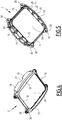
- the protection element 2 is a frame extending around the housing 6 and comprising at least one side wall 14 extending facing a side wall 8 of the housing 6 projecting from the outer face, that is to say facing an exposed portion of the housing 6, as shown in FIG. Fig. 3 .
- the side wall 14 extends in the direction of elevation so as to form a barrier facing a side wall of the housing 6.
- the frame comprises four side walls 14, each extending opposite one of the side faces 8 of the housing 6.
- the frame comprises two longitudinal side walls 16 extending substantially in the longitudinal direction and two transverse side walls 18 interconnecting the longitudinal side walls and extending substantially in the transverse direction, as more particularly visible on the Figs. 4 and 5 .
- Each side wall 16, 18 extends substantially parallel to the side face 8 of the housing 6 opposite which it extends.
- the transverse lateral walls 18 are the walls which are more particularly exposed to any projections of ballast or other since they extend substantially perpendicular to the direction of circulation of the railway vehicle.
- the transverse side walls 18 have a height, measured in the direction of elevation, greater than the height of the longitudinal side walls 16.
- the transverse side walls 18 rise in height. view of a large part of the corresponding side walls 8 of the housing, as shown in FIG. Fig. 3 .
- the frame thus has a shape substantially complementary to a portion of the contour of the housing 6 of the antenna 1.
- the shape of the side walls 14, 16, 18 of the protection element 2 is arranged so as not to disturb the operation of the antenna.
- the height of the walls is arranged to allow significant radiation from the antenna.
- one or more walls may comprise at least one groove 20 for the passage of cables connected to the antenna, as shown in FIGS. Figs. 4 and 5 .
- the frame formed by the protection element 2 further comprises a bottom wall 22 extending from the one or more side walls 14, 16, 18 and forming an opening 24, in which the antenna 1 is disposed.
- the bottom wall extends inside the frame towards the antenna 1, the bottom wall 22 and the opening 24 extending substantially in the same plane as the lower face 12 of the housing 6, as shown on the Fig. 3 .
- the frame has substantially the shape of an open cup in the bottom wall, as shown in FIG. Fig. 5 .
- the opening 24 has for example a shape substantially complementary to the contour of the lower face 12 of the housing 6.
- the antenna 1 and the protective element 2 form a relatively hermetic assembly against the intrusion of foreign bodies, such as for example ice or ballast, all by positioning the antenna closer to the track, and therefore tags, which improves its operation.
- a space extends between the edge of the opening 24, formed by the bottom wall 22, and the casing 6 of the antenna, to allow the flow of water or other fluid and to prevent a buildup of water or other fluid between the side walls 14, 16, 18 of the protection element 2 and the side faces 8 of the housing.
- This flow is represented by the arrows F at the Fig. 3 .
- the distance separating the edge of the opening 24 formed by the bottom wall 22 and the antenna 1 is for example less than 50 mm, so that the frame extends closer to the antenna 1.
- the transition 26 between the bottom wall 22 and the side walls 14, 16, 18 is for example rounded, as shown in FIG. Fig. 3 , so as to promote the flow of air around the frame and improve the aerodynamics of the antenna 1, as represented by the arrows F 'of the Fig. 3 .
- ribs 28 extend for example between the bottom wall 22 and the transverse lateral walls 18, as more particularly visible on the Fig. 5 .
- the ribs 28 extend substantially perpendicular to the transverse lateral walls 18 and to the bottom wall 22, so as to reinforce the transverse lateral walls 18 in the longitudinal direction.
- Such ribs 28 also make it possible to produce a frame of a single piece of substantially constant thickness, for example between 10 mm and 15 mm.
- Such a protective element 2 is made of a non-metallic material so as not to disturb the operation of the antenna.
- the protection element 2 is made of a composite material, comprising, for example, polyester filled with glass fibers, which makes it possible to produce a protective element 2 that is robust and lightweight, for example by injecting the composite material in a molding cavity having the shape of the frame to achieve.
- the antenna 1 is fixed on the outer face of the floor by means of a frame 4, shown in FIG. Fig. 6 .
- the frame 4 comprises side branches 30 extending on either side of the housing 6 of the antenna 1 in the transverse direction and projecting from the outer face of the floor.
- the protective element 2 is attached to the end portion of the lateral branches 30 spaced from the outer face of the floor so as to extend around the antenna 1, as shown on the Fig. 6 .
- the fixing of the protection element 2 is done for example by screws, for example by means of screws 32 and bolt 34, each screw 32 passing through an orifice 36 extending in the direction of elevation and provided in an ear 38. formed in the frame.
- the use of cage nuts and locking lock washers is particularly advantageous.
- the frame comprises for example four lugs 38 extending at the junction between the longitudinal side walls 16 and the transverse side walls 18.
- Each lug 38 defines for example a cavity on the outside of the frame, so that the head of the screw 32 introduced into the orifice 36 of the ear 38 extends into the cavity and is thus protected in the thickness of the frame.
- the ears 38 have for example a curvilinear shape offering significant resistance.
- the fixing of the protection element 2 on the frame 4 is such that the protection element 2 is spaced from the outer face of the floor and more particularly protects the part of the antenna 1 furthest from the outer face, which is also the part exposed to ballast or other projections from the track.
- the protection element 2 described above is compact and extends as close as possible to the antenna 1, so that the gauge constraints of the railway vehicle are respected.
- the protection offered by the protection element is for example dimensioned according to NF F07-101 (class K6) which represents the shocks produced by the ballast.
- the protection element 2 is easily accessible under the railway vehicle so that it can be changed simply and quickly in case of damage following ballast projections, for example.
Landscapes
- Engineering & Computer Science (AREA)
- Remote Sensing (AREA)
- Details Of Aerials (AREA)
Abstract
Description
- La présente invention concerne une voiture de véhicule ferroviaire, du type comprenant une caisse définissant un volume intérieur fermé par un plancher, une antenne, fixée sur une face externe dudit plancher opposée au volume intérieur, s'étendant en saillie de ladite face externe et comprenant un boîtier logeant des composants actifs de l'antenne, et un élément de protection de l'antenne fixé sur ladite face externe.
- Il est connu d'agencer au moins une antenne sous le plancher d'une voiture de véhicule ferroviaire afin d'assurer une communication entre le véhicule ferroviaire et des balises disposées le long de la voie sur laquelle circule le véhicule ferroviaire, par exemple afin d'assurer une géolocalisation du véhicule ferroviaire.
- Une telle antenne est donc exposée à l'extérieur de la voiture du véhicule ferroviaire et peut être endommagée, notamment par des projections de ballast ou en raison des conditions atmosphériques, notamment en hiver, par exemple par des projections de glace ou autre.
- Ainsi, il convient de protéger l'antenne afin qu'elle ne soit pas détériorée prématurément. Cependant, une telle protection ne doit pas interférer avec le bon fonctionnement de l'antenne, ce qui oblige à installer la protection assez loin de l'antenne et réduit l'efficacité de cette protection.
- L'un des buts de l'invention est de pallier les inconvénients ci-dessus en proposant une voiture de véhicule ferroviaire équipée d'une antenne protégée efficacement et sans perturbation de son fonctionnement.
- A cet effet, l'invention concerne une voiture de véhicule ferroviaire du type précité, dans laquelle l'élément de protection est un cadre réalisé en un matériau non métallique comprenant au moins une paroi latérale s'étendant en regard d'une partie de l'antenne en saillie de la face externe, ledit cadre présentant une forme sensiblement complémentaire du contour de l'antenne de sorte que le cadre s'étend autour de ladite antenne.
- En réalisant l'élément de protection en un matériau non métallique, on s'assure que l'élément de protection n'interfère pas avec le fonctionnement de l'antenne, ce qui permet de rapprocher l'élément de protection au plus près de l'antenne et ainsi d'en assurer une protection efficace, notamment contre les projections de ballast ou autre.
- Selon d'autres caractéristiques de la voiture de véhicule ferroviaire selon l'invention, prises isolément ou selon toute combinaison techniquement envisageable :
- le cadre comprend en outre une paroi de fond, s'étendant à partir de la paroi latérale vers l'antenne, ladite paroi de fond entourant une ouverture dans laquelle l'antenne est disposée ;
- le cadre comprend au moins une nervure s'étendant entre la paroi latérale et la paroi de fond en saillie desdites parois latérale et de fond ;
- la distance séparant un bord de l'ouverture formée par la paroi de fond et l'antenne est inférieure à 50 mm ;
- l'antenne est montée sur un châssis fixé à la face externe du plancher, ledit châssis s'étendant en saillie de la face externe et comprenant une partie extrême espacée de la face externe, l'élément de protection étant fixé à ladite partie extrême de sorte que ledit élément de protection est espacé de la face externe et protège la partie de l'antenne la plus éloignée de la face externe ;
- l'élément de protection est fixé au châssis par visseries ;
- l'élément de protection est réalisé en un matériau composite ;
- le matériau composite comprend du polyester chargé en fibres de verre ;
- le cadre comprend deux parois latérales longitudinales s'étendant selon la direction de circulation du véhicule ferroviaire et deux parois latérales transversales reliant lesdites parois longitudinales et s'étendant sensiblement perpendiculairement à la direction de circulation du véhicule ferroviaire, lesdites parois latérales transversales présentant une hauteur supérieure à celle des parois latérales longitudinales ; et
- la paroi latérale comprend au moins une gorge permettant le passage de câbles reliés à l'antenne.
- D'autres aspects et avantages de l'invention apparaîtront à la lecture de la description qui suit, donnée à titre d'exemple et faite en référence aux dessins annexés, dans lesquels :
- la
Fig. 1 est une représentation schématique en perspective, vue de dessus, d'un ensemble formé par une antenne et par un élément de protection selon l'invention, - la
Fig. 2 est une représentation schématique en perspective, vue de dessous, de l'ensemble de laFig. 1 , - la
Fig. 3 est une représentation schématique en coupe selon l'axe III-III de laFig. 1 , - les
Figs. 4 et 5 sont des représentations schématiques en perspective selon différents angles de vue de l'élément de protection de laFig. 1 , et - la
Fig. 6 est une représentation schématique en perspective de l'ensemble de laFig. 1 monté sur un châssis. - Dans la description, on définit le terme « longitudinal » selon la direction de circulation du véhicule ferroviaire, et le terme « transversal » selon une direction sensiblement perpendiculaire à la direction longitudinale correspondant à la direction d'écartement des rails sur lesquels circule le véhicule ferroviaire. La direction d'élévation est une direction perpendiculaire aux directions longitudinale et transversale.
- En référence aux
Figs. 1 et 2 , on décrit un ensemble, comprenant une antenne 1 et un élément de protection 2, destiné à être installé sous le plancher d'une voiture de véhicule ferroviaire. - Une telle voiture de véhicule ferroviaire comprend, de façon connue, une caisse définissant un volume intérieur, qui est fermé de son côté inférieur par le plancher. Ainsi, le plancher comprend une face interne du côté du volume intérieur et une face externe, à l'opposé du volume intérieur et s'étendant à l'extérieur de la voiture ferroviaire. Le plancher s'étend en regard de la voie sur laquelle circule le véhicule ferroviaire, la face externe étant tournée vers cette voie et étant donc exposée au ballast de la voie et aux conditions atmosphériques extérieures. La voie est équipée de balises réparties sur le trajet du véhicule ferroviaire et agencées pour assurer une communication entre les véhicules ferroviaires circulant sur la voie et des installations fixes du réseau ferroviaire, par exemple pour assurer une géolocalisation des véhicules ferroviaires.
- La communication avec les balises est assurée par l'antenne 1 fixée sur la face externe du plancher par l'intermédiaire d'un châssis 4, représenté sur la
Fig. 6 . - L'antenne 1 comprend un boîtier 6 logeant les composants actifs de l'antenne. Le fonctionnement de l'antenne 1 en coopération avec les balises est connu en soi et n'est pas l'objet de la présente invention. Il ne sera donc pas décrit plus en détail ici.
- Afin de ne pas perturber le rayonnement de l'antenne 1, le boîtier 6 est réalisé en un matériau non métallique, par exemple un matériau composite, formé d'une matrice en matière plastique renforcée par des fibres. Le boîtier 6 présente par exemple une forme sensiblement parallélépipédique, comprenant des faces latérales 8, s'étendant dans des plans sensiblement perpendiculaires au plancher et reliées par une face supérieure 10 et une face inférieure 12, s'étendant dans des plans sensiblement parallèle au plancher, comme représenté sur les
Figs. 1 et 2 . La fixation de l'antenne 1 sur la face externe du plancher est telle que l'antenne 1 s'étend en saillie selon la direction d'élévation du plancher, c'est-à-dire que l'antenne 1 s'étend en saillie du plancher vers le sol. Ainsi, en l'absence de l'élément de protection 2, le boîtier 6 est exposé et peut être endommagé rapidement par des projections de ballast ou autre du fait du matériau relativement fragile dans lequel il est réalisé. - L'élément de protection 2 est agencé pour empêcher les éventuelles projections d'atteindre le boîtier 6 et d'endommager l'antenne 1. A cet effet, l'élément de protection 2 est un cadre s'étendant autour du boîtier 6 et comprenant au moins une paroi latérale 14 s'étendant en regard d'une paroi latérale 8 du boîtier 6 en saillie de la face externe, c'est-à-dire en regard d'une partie exposée du boîtier 6, comme représenté sur la
Fig. 3 . La paroi latérale 14 s'étend selon la direction d'élévation de sorte à former une barrière en regard d'une paroi latérale du boîtier 6. - Selon le mode de réalisation représenté sur les figures, dans lequel le boîtier 6 présente une forme sensiblement parallélépipédique, le cadre comprend quatre parois latérales 14, s'étendant chacune en regard d'une des faces latérales 8 du boîtier 6. Ainsi, le cadre comprend deux parois latérales longitudinales 16 s'étendant sensiblement selon la direction longitudinale et deux parois latérales transversales 18 reliant entre elles les parois latérales longitudinales et s'étendant sensiblement selon la direction transversale, comme plus particulièrement visible sur les
Figs. 4 et 5 . Chaque paroi latérale 16, 18 s'étend sensiblement parallèlement à la face latérale 8 du boîtier 6 en regard de laquelle elle s'étend. Les parois latérales transversales 18 sont les parois qui sont plus particulièrement exposées aux éventuelles projections de ballast ou autre car elles s'étendent sensiblement perpendiculairement à la direction de circulation du véhicule ferroviaire. Afin d'améliorer la protection de l'antenne 1, les parois latérales transversales 18 présentent une hauteur, mesurée selon la direction d'élévation, supérieure à la hauteur des parois latérales longitudinales 16. Ainsi, les parois latérales transversales 18 s'élèvent en regard d'une grande partie des parois latérales 8 correspondantes du boîtier, comme représenté sur laFig. 3 . Le cadre présente ainsi une forme sensiblement complémentaire d'une partie du contour du boîtier 6 de l'antenne 1. - La forme des parois latérales 14, 16, 18 de l'élément de protection 2 est agencée pour ne pas perturber le fonctionnement de l'antenne. A cet effet, la hauteur des parois est agencée pour permettre un rayonnement important de l'antenne. En outre, une ou plusieurs parois peut comprendre au moins une gorge 20 permettant le passage de câbles reliés à l'antenne, comme représenté sur les
Figs. 4 et 5 . - Le cadre formé par l'élément de protection 2 comprend en outre une paroi de fond 22 s'étendant à partir de la ou des parois latérales 14, 16, 18 et formant une ouverture 24, dans laquelle l'antenne 1 est disposée. Ainsi, la paroi de fond s'étend à l'intérieur du cadre vers l'antenne 1, la paroi de fond 22 et l'ouverture 24 s'étendant sensiblement dans le même plan que la face inférieure 12 du boîtier 6, comme représenté sur la
Fig. 3 . Ainsi, le cadre présente sensiblement la forme d'une cuvette ouverte dans la paroi de fond, comme représenté sur laFig. 5 . L'ouverture 24 présente par exemple une forme sensiblement complémentaire du contour de la face inférieure 12 du boîtier 6. Ainsi, l'antenne 1 et l'élément de protection 2 forment un ensemble relativement hermétique contre l'intrusion de corps étrangers, comme par exemple de la glace ou du ballast, tout en positionnant l'antenne au plus près de la voie, et donc des balises, ce qui en améliore le fonctionnement. - Un espace s'étend entre le bord de l'ouverture 24, formé par la paroi de fond 22, et le boîtier 6 de l'antenne, afin de permettre l'écoulement d'eau ou autre fluide et éviter une accumulation d'eau ou autre fluide entre les parois latérales 14, 16, 18 de l'élément de protection 2 et les faces latérales 8 du boîtier. Cet écoulement est représenté par les flèches F à la
Fig. 3 . La distance séparant le bord de l'ouverture 24 formée par la paroi de fond 22 et l'antenne 1 est par exemple inférieure à 50 mm, de sorte que le cadre s'étend au plus près de l'antenne 1. - Sur l'extérieur du cadre, la transition 26 entre la paroi de fond 22 et les parois latérales 14, 16, 18 est par exemple arrondie, comme représenté sur la
Fig. 3 , de sorte à favoriser l'écoulement d'air autour du cadre et améliorer l'aérodynamisme de l'antenne 1, comme représenté par les flèches F' de laFig. 3 . - Afin de renforcer la résistance mécanique des parois latérales transversales 18, les plus soumises à des contraintes comme indiqué précédemment, des nervures 28 s'étendent par exemple entre la paroi de fond 22 et les parois latérales transversales 18, comme plus particulièrement visible sur la
Fig. 5 . Les nervures 28 s'étendent sensiblement perpendiculairement aux parois latérales transversales 18 et à la paroi de fond 22, de sorte à renforcer les parois latérales transversales 18 selon la direction longitudinale. De telles nervures 28 permettent également de rendre possible la réalisation d'un cadre d'une seule pièce d'épaisseur sensiblement constante, par exemple comprise entre 10 mm et 15 mm. - Un tel élément de protection 2 est réalisé en un matériau non-métallique afin de ne pas perturber le fonctionnement de l'antenne. A titre d'exemple, l'élément de protection 2 est réalisé en matériau composite, comprenant par exemple du polyester chargé en fibres de verre, ce qui permet de réaliser un élément de protection 2 robuste et léger, par exemple par injection du matériau composite dans une cavité de moulage présentant la forme du cadre à réaliser.
- Comme indiqué précédemment, l'antenne 1 est fixée sur la face externe du plancher au moyen d'un châssis 4, représenté sur la
Fig. 6 . Le châssis 4 comprend des branches latérales 30 s'étendant de part et d'autre du boîtier 6 de l'antenne 1 selon la direction transversale et en saillie de la face externe du plancher. L'élément de protection 2 est fixé à la partie extrême des branches latérales 30 espacée de la face externe du plancher de sorte à s'étendre autour de l'antenne 1, comme représenté sur laFig. 6 . La fixation de l'élément de protection 2 se fait par exemple par visseries, par exemple au moyen de vis 32 et boulon 34, chaque vis 32 passant par un orifice 36 s'étendant selon la direction d'élévation et prévu dans une oreille 38 formée dans le cadre. L'utilisation d'écrous cage et de rondelles à crans de verrouillage est particulièrement avantageuse. Le cadre comprend par exemple quatre oreilles 38 s'étendant à la jonction entre les parois latérales longitudinales 16 et les parois latérales transversales 18. Chaque oreille 38 définit par exemple une cavité du côté extérieur du cadre, de sorte que la tête de la vis 32 introduite dans l'orifice 36 de l'oreille 38 s'étend dans la cavité et est ainsi protégée dans l'épaisseur du cadre. Les oreilles 38 présentent par exemple une forme curviligne offrant une résistance importante. - La fixation de l'élément de protection 2 sur le châssis 4 est telle que l'élément de protection 2 est espacé de la face externe du plancher et protège plus particulièrement la partie de l'antenne 1 la plus éloignée de la face externe, qui est également la partie exposée aux projections de ballast ou autre en provenance de la voie.
- L'élément de protection 2 décrit ci-dessus est compact et s'étend au plus près de l'antenne 1, de sorte que les contraintes de gabarit du véhicule ferroviaire sont respectées.
- La protection offerte par l'élément de protection est par exemple dimensionnée selon la norme NF F07-101 (classe K6) qui représente les chocs produits par le ballast.
- L'élément de protection 2 est facilement accessible sous le véhicule ferroviaire de sorte qu'il peut être changé de façon simple et rapide en cas d'endommagement suite à des projections de ballast par exemple.
Claims (9)
- Voiture de véhicule ferroviaire comprenant une caisse définissant un volume intérieur fermé par un plancher, une antenne (1), fixée sur une face externe dudit plancher opposée au volume intérieur, s'étendant en saillie de ladite face externe et comprenant un boîtier (6) logeant des composants actifs de l'antenne, et un élément de protection (2) de l'antenne (1) fixé sur ladite face externe, l'élément de protection (2) étant un cadre réalisé en un matériau non métallique comprenant au moins une paroi latérale (14, 16, 18) s'étendant en regard d'une partie de l'antenne (1) en saillie de la face externe, ledit cadre présentant une forme sensiblement complémentaire du contour de l'antenne (1) de sorte que le cadre s'étend autour de ladite antenne (1),
caractérisée en ce que le cadre comprend en outre une paroi de fond (22), s'étendant à partir de la paroi latérale (14, 16, 18) vers l'antenne (1), ladite paroi de fond (22) entourant une ouverture (24) dans laquelle l'antenne (1) est disposée. - Voiture de véhicule ferroviaire selon la revendication 1, dans laquelle le cadre comprend au moins une nervure (28) s'étendant entre la paroi latérale (14, 18) et la paroi de fond (22) en saillie desdites parois latérale (14, 18) et de fond (22).
- Voiture de véhicule ferroviaire selon la revendication 1 ou 2, dans laquelle la distance séparant un bord de l'ouverture (24) formée par la paroi de fond (22) et l'antenne (1) est inférieure à 50 mm.
- Voiture de véhicule ferroviaire selon l'une quelconque des revendications 1 à 3, dans laquelle l'antenne (1) est montée sur un châssis (4) fixé à la face externe du plancher, ledit châssis (4) s'étendant en saillie de la face externe et comprenant une partie extrême espacée de la face externe, l'élément de protection (2) étant fixé à ladite partie extrême de sorte que ledit élément de protection (2) est espacé de la face externe et protège la partie de l'antenne (1) la plus éloignée de la face externe.
- Voiture de véhicule ferroviaire selon la revendication 4, dans laquelle l'élément de protection (2) est fixé au châssis (4) par visseries.
- Voiture de véhicule ferroviaire selon l'une quelconque des revendications 1 à 5, dans laquelle l'élément de protection (2) est réalisé en un matériau composite.
- Voiture de véhicule ferroviaire selon la revendication 6, dans laquelle le matériau composite comprend du polyester chargé en fibres de verre.
- Voiture de véhicule ferroviaire selon l'une quelconque des revendication 1 à 7, dans laquelle le cadre comprend deux parois latérales longitudinales (16) s'étendant selon la direction de circulation du véhicule ferroviaire et deux parois latérales transversales (18) reliant lesdites parois longitudinales (16) et s'étendant sensiblement perpendiculairement à la direction de circulation du véhicule ferroviaire, lesdites parois latérales transversales (18) présentant une hauteur supérieure à celle des parois latérales longitudinales (16).
- Voiture de véhicule ferroviaire selon l'une quelconque des revendications 1 à 8, dans laquelle la paroi latérale (14, 16, 18) comprend au moins une gorge (20) permettant le passage de câbles reliés à l'antenne (1).
Applications Claiming Priority (1)
| Application Number | Priority Date | Filing Date | Title |
|---|---|---|---|
| FR1758958A FR3071673B1 (fr) | 2017-09-27 | 2017-09-27 | Element de protection d'une antenne prevue sous le plancher d'un vehicule ferroviaire |
Publications (2)
| Publication Number | Publication Date |
|---|---|
| EP3462535A1 true EP3462535A1 (fr) | 2019-04-03 |
| EP3462535B1 EP3462535B1 (fr) | 2020-11-04 |
Family
ID=60302332
Family Applications (1)
| Application Number | Title | Priority Date | Filing Date |
|---|---|---|---|
| EP18196974.2A Active EP3462535B1 (fr) | 2017-09-27 | 2018-09-26 | Elément de protection d'une antenne prévue sous le plancher d'un véhicule ferroviaire |
Country Status (2)
| Country | Link |
|---|---|
| EP (1) | EP3462535B1 (fr) |
| FR (1) | FR3071673B1 (fr) |
Cited By (1)
| Publication number | Priority date | Publication date | Assignee | Title |
|---|---|---|---|---|
| EP3920331A1 (fr) | 2020-06-03 | 2021-12-08 | Bombardier Transportation GmbH | Dispositif de protection et véhicule ferroviaire doté d'un dispositif de protection |
Citations (3)
| Publication number | Priority date | Publication date | Assignee | Title |
|---|---|---|---|---|
| EP2599682A1 (fr) * | 2011-11-30 | 2013-06-05 | Bombardier Transportation GmbH | Dispositif de protection pour un composant sur la face inférieure d'un véhicule sur rails |
| US20140156135A1 (en) * | 2012-11-30 | 2014-06-05 | Kabushiki Kaisha Toshiba | Vehicle control device for railroad vehicle and vehicle control system for railroad vehicle |
| EP3121091A1 (fr) * | 2015-07-16 | 2017-01-25 | Bombardier Transportation GmbH | Supports d'antennes |
-
2017
- 2017-09-27 FR FR1758958A patent/FR3071673B1/fr not_active Expired - Fee Related
-
2018
- 2018-09-26 EP EP18196974.2A patent/EP3462535B1/fr active Active
Patent Citations (3)
| Publication number | Priority date | Publication date | Assignee | Title |
|---|---|---|---|---|
| EP2599682A1 (fr) * | 2011-11-30 | 2013-06-05 | Bombardier Transportation GmbH | Dispositif de protection pour un composant sur la face inférieure d'un véhicule sur rails |
| US20140156135A1 (en) * | 2012-11-30 | 2014-06-05 | Kabushiki Kaisha Toshiba | Vehicle control device for railroad vehicle and vehicle control system for railroad vehicle |
| EP3121091A1 (fr) * | 2015-07-16 | 2017-01-25 | Bombardier Transportation GmbH | Supports d'antennes |
Cited By (2)
| Publication number | Priority date | Publication date | Assignee | Title |
|---|---|---|---|---|
| EP3920331A1 (fr) | 2020-06-03 | 2021-12-08 | Bombardier Transportation GmbH | Dispositif de protection et véhicule ferroviaire doté d'un dispositif de protection |
| DE102020114776A1 (de) | 2020-06-03 | 2021-12-09 | Bombardier Transportation Gmbh | Schutzvorrichtung und Schienenfahrzeug mit einer Schutzvorrichtung |
Also Published As
| Publication number | Publication date |
|---|---|
| EP3462535B1 (fr) | 2020-11-04 |
| FR3071673B1 (fr) | 2020-11-06 |
| FR3071673A1 (fr) | 2019-03-29 |
Similar Documents
| Publication | Publication Date | Title |
|---|---|---|
| FR2861348A1 (fr) | Montage d'une camera de vision arriere dans un boitier de protection comportant une fenetre de vision | |
| EP3634800B1 (fr) | Dispositif d'obturation d'entree d'air de vehicule automobile et procede de fabrication d'un tel dispositif d'obturation | |
| EP2546614B1 (fr) | Dispositif capteur ou détecteur avec un bouchon guide-câble perfectionné | |
| FR3083513A1 (fr) | Agencement d'un soubassement de caisse d'un vehicule integrant un ensemble de batteries et vehicule ayant un tel agencement | |
| EP3462535B1 (fr) | Elément de protection d'une antenne prévue sous le plancher d'un véhicule ferroviaire | |
| FR3111597A1 (fr) | Absorbeur de choc pour parechoc avant de véhicule automobile | |
| EP3300196A1 (fr) | Tête de chambre de raccordement pourvue d'un coffrage réglable en hauteur | |
| EP1098819B1 (fr) | Dispositif de transport de poches de sang | |
| EP3319835B1 (fr) | Élément de dispositif d'éclairage limitant la rétention d'eau a proximité d'un joint d'étanchéité | |
| FR2893568A1 (fr) | Coffre logistique | |
| FR3135660A1 (fr) | Porte latérale de véhicule automobile et véhicule comportant une telle porte | |
| EP2008918A1 (fr) | Garde-boue de véhicule automobile et véhicule automobile associé | |
| WO2021069812A1 (fr) | Dispositif d'obturation d'un conduit muni d'un appareil de mesure comprenant un emetteur | |
| FR2479366A1 (fr) | Panneau de meuble equipe d'un boitier de montage d'un composant d'armature | |
| FR3037286A1 (fr) | Ensemble d'une caisse en blanc de vehicule automobile et d'un hayon comportant un verin en zone seche | |
| FR3005678A1 (fr) | Armature pour coffre de volet | |
| WO2013011219A1 (fr) | Vehicule automobile a portiere coulissante | |
| FR2948403A1 (fr) | Ventouse electromagnetique comportant une source lumineuse | |
| FR3140331A1 (fr) | Obturateur pour garniture intérieure de véhicule automobile et véhicule automobile équipé d’un tel obturateur | |
| WO2016166441A1 (fr) | Structure de face avant technique de véhicule automobile en matière plastique | |
| EP4251476A1 (fr) | Dispositif absorbeur d'energie | |
| FR2847879A1 (fr) | Embarcation pneumatique | |
| EP2692665B1 (fr) | Citerne constituée par une partie cylindrique fermée à son extrémité par un fond | |
| FR3087050A1 (fr) | Boîtier de batterie | |
| FR2914708A3 (fr) | Assemblage d'une premiere et d'une seconde piece au moyen d'un dispositif de fixation par serrage |
Legal Events
| Date | Code | Title | Description |
|---|---|---|---|
| PUAI | Public reference made under article 153(3) epc to a published international application that has entered the european phase |
Free format text: ORIGINAL CODE: 0009012 |
|
| STAA | Information on the status of an ep patent application or granted ep patent |
Free format text: STATUS: THE APPLICATION HAS BEEN PUBLISHED |
|
| AK | Designated contracting states |
Kind code of ref document: A1 Designated state(s): AL AT BE BG CH CY CZ DE DK EE ES FI FR GB GR HR HU IE IS IT LI LT LU LV MC MK MT NL NO PL PT RO RS SE SI SK SM TR |
|
| AX | Request for extension of the european patent |
Extension state: BA ME |
|
| STAA | Information on the status of an ep patent application or granted ep patent |
Free format text: STATUS: REQUEST FOR EXAMINATION WAS MADE |
|
| 17P | Request for examination filed |
Effective date: 20190412 |
|
| RBV | Designated contracting states (corrected) |
Designated state(s): AL AT BE BG CH CY CZ DE DK EE ES FI FR GB GR HR HU IE IS IT LI LT LU LV MC MK MT NL NO PL PT RO RS SE SI SK SM TR |
|
| GRAP | Despatch of communication of intention to grant a patent |
Free format text: ORIGINAL CODE: EPIDOSNIGR1 |
|
| STAA | Information on the status of an ep patent application or granted ep patent |
Free format text: STATUS: GRANT OF PATENT IS INTENDED |
|
| INTG | Intention to grant announced |
Effective date: 20200529 |
|
| GRAS | Grant fee paid |
Free format text: ORIGINAL CODE: EPIDOSNIGR3 |
|
| GRAA | (expected) grant |
Free format text: ORIGINAL CODE: 0009210 |
|
| STAA | Information on the status of an ep patent application or granted ep patent |
Free format text: STATUS: THE PATENT HAS BEEN GRANTED |
|
| AK | Designated contracting states |
Kind code of ref document: B1 Designated state(s): AL AT BE BG CH CY CZ DE DK EE ES FI FR GB GR HR HU IE IS IT LI LT LU LV MC MK MT NL NO PL PT RO RS SE SI SK SM TR |
|
| REG | Reference to a national code |
Ref country code: GB Ref legal event code: FG4D Free format text: NOT ENGLISH |
|
| REG | Reference to a national code |
Ref country code: CH Ref legal event code: EP |
|
| REG | Reference to a national code |
Ref country code: AT Ref legal event code: REF Ref document number: 1332017 Country of ref document: AT Kind code of ref document: T Effective date: 20201115 |
|
| REG | Reference to a national code |
Ref country code: IE Ref legal event code: FG4D Free format text: LANGUAGE OF EP DOCUMENT: FRENCH |
|
| REG | Reference to a national code |
Ref country code: DE Ref legal event code: R096 Ref document number: 602018009390 Country of ref document: DE |
|
| REG | Reference to a national code |
Ref country code: NL Ref legal event code: MP Effective date: 20201104 |
|
| PG25 | Lapsed in a contracting state [announced via postgrant information from national office to epo] |
Ref country code: RS Free format text: LAPSE BECAUSE OF FAILURE TO SUBMIT A TRANSLATION OF THE DESCRIPTION OR TO PAY THE FEE WITHIN THE PRESCRIBED TIME-LIMIT Effective date: 20201104 Ref country code: PT Free format text: LAPSE BECAUSE OF FAILURE TO SUBMIT A TRANSLATION OF THE DESCRIPTION OR TO PAY THE FEE WITHIN THE PRESCRIBED TIME-LIMIT Effective date: 20210304 Ref country code: FI Free format text: LAPSE BECAUSE OF FAILURE TO SUBMIT A TRANSLATION OF THE DESCRIPTION OR TO PAY THE FEE WITHIN THE PRESCRIBED TIME-LIMIT Effective date: 20201104 Ref country code: NO Free format text: LAPSE BECAUSE OF FAILURE TO SUBMIT A TRANSLATION OF THE DESCRIPTION OR TO PAY THE FEE WITHIN THE PRESCRIBED TIME-LIMIT Effective date: 20210204 Ref country code: GR Free format text: LAPSE BECAUSE OF FAILURE TO SUBMIT A TRANSLATION OF THE DESCRIPTION OR TO PAY THE FEE WITHIN THE PRESCRIBED TIME-LIMIT Effective date: 20210205 |
|
| PG25 | Lapsed in a contracting state [announced via postgrant information from national office to epo] |
Ref country code: ES Free format text: LAPSE BECAUSE OF FAILURE TO SUBMIT A TRANSLATION OF THE DESCRIPTION OR TO PAY THE FEE WITHIN THE PRESCRIBED TIME-LIMIT Effective date: 20201104 Ref country code: BG Free format text: LAPSE BECAUSE OF FAILURE TO SUBMIT A TRANSLATION OF THE DESCRIPTION OR TO PAY THE FEE WITHIN THE PRESCRIBED TIME-LIMIT Effective date: 20210204 Ref country code: SE Free format text: LAPSE BECAUSE OF FAILURE TO SUBMIT A TRANSLATION OF THE DESCRIPTION OR TO PAY THE FEE WITHIN THE PRESCRIBED TIME-LIMIT Effective date: 20201104 Ref country code: PL Free format text: LAPSE BECAUSE OF FAILURE TO SUBMIT A TRANSLATION OF THE DESCRIPTION OR TO PAY THE FEE WITHIN THE PRESCRIBED TIME-LIMIT Effective date: 20201104 Ref country code: IS Free format text: LAPSE BECAUSE OF FAILURE TO SUBMIT A TRANSLATION OF THE DESCRIPTION OR TO PAY THE FEE WITHIN THE PRESCRIBED TIME-LIMIT Effective date: 20210304 Ref country code: LV Free format text: LAPSE BECAUSE OF FAILURE TO SUBMIT A TRANSLATION OF THE DESCRIPTION OR TO PAY THE FEE WITHIN THE PRESCRIBED TIME-LIMIT Effective date: 20201104 |
|
| REG | Reference to a national code |
Ref country code: LT Ref legal event code: MG9D |
|
| PG25 | Lapsed in a contracting state [announced via postgrant information from national office to epo] |
Ref country code: HR Free format text: LAPSE BECAUSE OF FAILURE TO SUBMIT A TRANSLATION OF THE DESCRIPTION OR TO PAY THE FEE WITHIN THE PRESCRIBED TIME-LIMIT Effective date: 20201104 |
|
| PG25 | Lapsed in a contracting state [announced via postgrant information from national office to epo] |
Ref country code: LT Free format text: LAPSE BECAUSE OF FAILURE TO SUBMIT A TRANSLATION OF THE DESCRIPTION OR TO PAY THE FEE WITHIN THE PRESCRIBED TIME-LIMIT Effective date: 20201104 Ref country code: SK Free format text: LAPSE BECAUSE OF FAILURE TO SUBMIT A TRANSLATION OF THE DESCRIPTION OR TO PAY THE FEE WITHIN THE PRESCRIBED TIME-LIMIT Effective date: 20201104 Ref country code: RO Free format text: LAPSE BECAUSE OF FAILURE TO SUBMIT A TRANSLATION OF THE DESCRIPTION OR TO PAY THE FEE WITHIN THE PRESCRIBED TIME-LIMIT Effective date: 20201104 Ref country code: SM Free format text: LAPSE BECAUSE OF FAILURE TO SUBMIT A TRANSLATION OF THE DESCRIPTION OR TO PAY THE FEE WITHIN THE PRESCRIBED TIME-LIMIT Effective date: 20201104 Ref country code: EE Free format text: LAPSE BECAUSE OF FAILURE TO SUBMIT A TRANSLATION OF THE DESCRIPTION OR TO PAY THE FEE WITHIN THE PRESCRIBED TIME-LIMIT Effective date: 20201104 Ref country code: CZ Free format text: LAPSE BECAUSE OF FAILURE TO SUBMIT A TRANSLATION OF THE DESCRIPTION OR TO PAY THE FEE WITHIN THE PRESCRIBED TIME-LIMIT Effective date: 20201104 |
|
| REG | Reference to a national code |
Ref country code: DE Ref legal event code: R097 Ref document number: 602018009390 Country of ref document: DE |
|
| PG25 | Lapsed in a contracting state [announced via postgrant information from national office to epo] |
Ref country code: DK Free format text: LAPSE BECAUSE OF FAILURE TO SUBMIT A TRANSLATION OF THE DESCRIPTION OR TO PAY THE FEE WITHIN THE PRESCRIBED TIME-LIMIT Effective date: 20201104 |
|
| PLBE | No opposition filed within time limit |
Free format text: ORIGINAL CODE: 0009261 |
|
| STAA | Information on the status of an ep patent application or granted ep patent |
Free format text: STATUS: NO OPPOSITION FILED WITHIN TIME LIMIT |
|
| 26N | No opposition filed |
Effective date: 20210805 |
|
| PG25 | Lapsed in a contracting state [announced via postgrant information from national office to epo] |
Ref country code: IT Free format text: LAPSE BECAUSE OF FAILURE TO SUBMIT A TRANSLATION OF THE DESCRIPTION OR TO PAY THE FEE WITHIN THE PRESCRIBED TIME-LIMIT Effective date: 20201104 Ref country code: NL Free format text: LAPSE BECAUSE OF FAILURE TO SUBMIT A TRANSLATION OF THE DESCRIPTION OR TO PAY THE FEE WITHIN THE PRESCRIBED TIME-LIMIT Effective date: 20201104 Ref country code: AL Free format text: LAPSE BECAUSE OF FAILURE TO SUBMIT A TRANSLATION OF THE DESCRIPTION OR TO PAY THE FEE WITHIN THE PRESCRIBED TIME-LIMIT Effective date: 20201104 |
|
| PG25 | Lapsed in a contracting state [announced via postgrant information from national office to epo] |
Ref country code: SI Free format text: LAPSE BECAUSE OF FAILURE TO SUBMIT A TRANSLATION OF THE DESCRIPTION OR TO PAY THE FEE WITHIN THE PRESCRIBED TIME-LIMIT Effective date: 20201104 |
|
| REG | Reference to a national code |
Ref country code: CH Ref legal event code: PL |
|
| REG | Reference to a national code |
Ref country code: BE Ref legal event code: MM Effective date: 20210930 |
|
| PG25 | Lapsed in a contracting state [announced via postgrant information from national office to epo] |
Ref country code: IS Free format text: LAPSE BECAUSE OF FAILURE TO SUBMIT A TRANSLATION OF THE DESCRIPTION OR TO PAY THE FEE WITHIN THE PRESCRIBED TIME-LIMIT Effective date: 20210304 Ref country code: MC Free format text: LAPSE BECAUSE OF FAILURE TO SUBMIT A TRANSLATION OF THE DESCRIPTION OR TO PAY THE FEE WITHIN THE PRESCRIBED TIME-LIMIT Effective date: 20201104 |
|
| PG25 | Lapsed in a contracting state [announced via postgrant information from national office to epo] |
Ref country code: LU Free format text: LAPSE BECAUSE OF NON-PAYMENT OF DUE FEES Effective date: 20210926 Ref country code: IE Free format text: LAPSE BECAUSE OF NON-PAYMENT OF DUE FEES Effective date: 20210926 Ref country code: BE Free format text: LAPSE BECAUSE OF NON-PAYMENT OF DUE FEES Effective date: 20210930 |
|
| PG25 | Lapsed in a contracting state [announced via postgrant information from national office to epo] |
Ref country code: LI Free format text: LAPSE BECAUSE OF NON-PAYMENT OF DUE FEES Effective date: 20210930 Ref country code: CH Free format text: LAPSE BECAUSE OF NON-PAYMENT OF DUE FEES Effective date: 20210930 |
|
| REG | Reference to a national code |
Ref country code: AT Ref legal event code: UEP Ref document number: 1332017 Country of ref document: AT Kind code of ref document: T Effective date: 20201104 |
|
| GBPC | Gb: european patent ceased through non-payment of renewal fee |
Effective date: 20220926 |
|
| PG25 | Lapsed in a contracting state [announced via postgrant information from national office to epo] |
Ref country code: CY Free format text: LAPSE BECAUSE OF FAILURE TO SUBMIT A TRANSLATION OF THE DESCRIPTION OR TO PAY THE FEE WITHIN THE PRESCRIBED TIME-LIMIT Effective date: 20201104 |
|
| PG25 | Lapsed in a contracting state [announced via postgrant information from national office to epo] |
Ref country code: HU Free format text: LAPSE BECAUSE OF FAILURE TO SUBMIT A TRANSLATION OF THE DESCRIPTION OR TO PAY THE FEE WITHIN THE PRESCRIBED TIME-LIMIT; INVALID AB INITIO Effective date: 20180926 |
|
| P01 | Opt-out of the competence of the unified patent court (upc) registered |
Effective date: 20230823 |
|
| PG25 | Lapsed in a contracting state [announced via postgrant information from national office to epo] |
Ref country code: GB Free format text: LAPSE BECAUSE OF NON-PAYMENT OF DUE FEES Effective date: 20220926 |
|
| PG25 | Lapsed in a contracting state [announced via postgrant information from national office to epo] |
Ref country code: MK Free format text: LAPSE BECAUSE OF FAILURE TO SUBMIT A TRANSLATION OF THE DESCRIPTION OR TO PAY THE FEE WITHIN THE PRESCRIBED TIME-LIMIT Effective date: 20201104 |
|
| PG25 | Lapsed in a contracting state [announced via postgrant information from national office to epo] |
Ref country code: MT Free format text: LAPSE BECAUSE OF FAILURE TO SUBMIT A TRANSLATION OF THE DESCRIPTION OR TO PAY THE FEE WITHIN THE PRESCRIBED TIME-LIMIT Effective date: 20201104 |
|
| PGFP | Annual fee paid to national office [announced via postgrant information from national office to epo] |
Ref country code: DE Payment date: 20250919 Year of fee payment: 8 |
|
| PGFP | Annual fee paid to national office [announced via postgrant information from national office to epo] |
Ref country code: FR Payment date: 20250922 Year of fee payment: 8 Ref country code: AT Payment date: 20250919 Year of fee payment: 8 |
|
| PG25 | Lapsed in a contracting state [announced via postgrant information from national office to epo] |
Ref country code: TR Free format text: LAPSE BECAUSE OF FAILURE TO SUBMIT A TRANSLATION OF THE DESCRIPTION OR TO PAY THE FEE WITHIN THE PRESCRIBED TIME-LIMIT Effective date: 20201104 |