EP3462473A1 - Electrical switching apparatus and accessory wire retention assembly therefore - Google Patents
Electrical switching apparatus and accessory wire retention assembly therefore Download PDFInfo
- Publication number
- EP3462473A1 EP3462473A1 EP18187155.9A EP18187155A EP3462473A1 EP 3462473 A1 EP3462473 A1 EP 3462473A1 EP 18187155 A EP18187155 A EP 18187155A EP 3462473 A1 EP3462473 A1 EP 3462473A1
- Authority
- EP
- European Patent Office
- Prior art keywords
- wires
- accessory
- retention assembly
- housing
- wire retention
- Prior art date
- Legal status (The legal status is an assumption and is not a legal conclusion. Google has not performed a legal analysis and makes no representation as to the accuracy of the status listed.)
- Granted
Links
Images



Classifications
-
- H—ELECTRICITY
- H01—ELECTRIC ELEMENTS
- H01H—ELECTRIC SWITCHES; RELAYS; SELECTORS; EMERGENCY PROTECTIVE DEVICES
- H01H71/00—Details of the protective switches or relays covered by groups H01H73/00 - H01H83/00
- H01H71/02—Housings; Casings; Bases; Mountings
- H01H71/0207—Mounting or assembling the different parts of the circuit breaker
- H01H71/0228—Mounting or assembling the different parts of the circuit breaker having provisions for interchangeable or replaceable parts
-
- H—ELECTRICITY
- H01—ELECTRIC ELEMENTS
- H01H—ELECTRIC SWITCHES; RELAYS; SELECTORS; EMERGENCY PROTECTIVE DEVICES
- H01H71/00—Details of the protective switches or relays covered by groups H01H73/00 - H01H83/00
- H01H71/02—Housings; Casings; Bases; Mountings
- H01H71/0207—Mounting or assembling the different parts of the circuit breaker
- H01H71/0214—Housing or casing lateral walls containing guiding grooves or special mounting facilities
-
- H—ELECTRICITY
- H01—ELECTRIC ELEMENTS
- H01H—ELECTRIC SWITCHES; RELAYS; SELECTORS; EMERGENCY PROTECTIVE DEVICES
- H01H71/00—Details of the protective switches or relays covered by groups H01H73/00 - H01H83/00
- H01H71/10—Operating or release mechanisms
- H01H71/1009—Interconnected mechanisms
-
- H—ELECTRICITY
- H01—ELECTRIC ELEMENTS
- H01H—ELECTRIC SWITCHES; RELAYS; SELECTORS; EMERGENCY PROTECTIVE DEVICES
- H01H9/00—Details of switching devices, not covered by groups H01H1/00 - H01H7/00
- H01H9/02—Bases, casings, or covers
-
- H—ELECTRICITY
- H01—ELECTRIC ELEMENTS
- H01H—ELECTRIC SWITCHES; RELAYS; SELECTORS; EMERGENCY PROTECTIVE DEVICES
- H01H9/00—Details of switching devices, not covered by groups H01H1/00 - H01H7/00
- H01H9/08—Arrangements to facilitate replacement of a switch, e.g. cartridge housing
- H01H9/085—Arrangements to facilitate replacement of a switch, e.g. cartridge housing contact separation effected by removing contact carrying element
-
- H—ELECTRICITY
- H02—GENERATION; CONVERSION OR DISTRIBUTION OF ELECTRIC POWER
- H02B—BOARDS, SUBSTATIONS OR SWITCHING ARRANGEMENTS FOR THE SUPPLY OR DISTRIBUTION OF ELECTRIC POWER
- H02B11/00—Switchgear having carriage withdrawable for isolation
- H02B11/02—Details
- H02B11/04—Isolating-contacts, e.g. mountings or shieldings
-
- H—ELECTRICITY
- H01—ELECTRIC ELEMENTS
- H01H—ELECTRIC SWITCHES; RELAYS; SELECTORS; EMERGENCY PROTECTIVE DEVICES
- H01H71/00—Details of the protective switches or relays covered by groups H01H73/00 - H01H83/00
- H01H71/02—Housings; Casings; Bases; Mountings
- H01H71/0264—Mountings or coverplates for complete assembled circuit breakers, e.g. snap mounting in panel
- H01H71/0271—Mounting several complete assembled circuit breakers together
- H01H2071/0278—Mounting several complete assembled circuit breakers together with at least one of juxtaposed casings dedicated to an auxiliary device, e.g. for undervoltage or shunt trip
-
- H—ELECTRICITY
- H01—ELECTRIC ELEMENTS
- H01H—ELECTRIC SWITCHES; RELAYS; SELECTORS; EMERGENCY PROTECTIVE DEVICES
- H01H71/00—Details of the protective switches or relays covered by groups H01H73/00 - H01H83/00
- H01H71/02—Housings; Casings; Bases; Mountings
- H01H2071/0292—Housing or frames containing grooves or slots for guiding movable parts
Definitions
- the disclosed concept relates generally to electrical switching apparatus and, more particularly, to electric switching apparatus, such as for example, circuit breakers.
- the disclosed concept also relates to accessory wire retention assemblies for circuit breakers.
- Electrical switching apparatus such as circuit breakers, as well as transfer switches, network protectors and the like, are often equipped with components or accessories such as, for example and without limitation, printed circuit boards (PCB's), trip actuator assemblies, auxiliary switches, shunt trip devices, under voltage release devices, and bell alarms.
- PCB's printed circuit boards
- Such devices can be employed in a variety of ways to provide signals indicating certain conditions within the apparatus and/or to initiate a change in status of the apparatus such as, for example, to trip open the separable contacts of the apparatus in response to an electrical fault condition (e.g., without limitation, current overload; short circuit; abnormal voltage).
- an electrical fault condition e.g., without limitation, current overload; short circuit; abnormal voltage
- Some accessories include electrical conductors (e.g., wires). Available space within the circuit breaker housing for mounting accessories and routing the corresponding wires is limited. Wires must also be routed properly to avoid interference with internal circuit breaker components and to comply with agency code requirements, for example, with respect clearance and strain relief regulations.
- electrical conductors e.g., wires
- an accessory wire retention assembly for an electrical switching apparatus.
- the electrical switching apparatus comprises a housing, separable contacts and an accessory enclosed by the housing, an operating mechanism for opening and closing the separable contacts, and a number of wires adapted to be electrically connected to the accessory.
- the housing includes an interior, an exterior, and an aperture. The wires extend from the interior through the aperture to the exterior.
- the accessory wire retention assembly comprises: an insert structured to cooperate with the housing and to establish a predetermined position of the wires with respect to the accessory and the aperture; and a fastening mechanism structured to fasten the wires to the insert to maintain the wires in the predetermined position.
- the insert may be an elongated molded member comprising a number of molded features structured to cooperate with the housing, the wires, and the fastening mechanism.
- the molded features may include a fastening portion for receiving the fastening mechanism and maintaining the position of the fastening mechanism.
- the housing may further include a base and a cover coupled to the base, wherein the aperture extends through the base.
- the molded features may include a guide portion structured to cooperate with the base to accurately position the insert and the wires proximate the accessary and the aperture.
- the molded features may further include a locking portion, wherein the locking portion is structured to cooperate with the cover to lock the insert in position when the cover is installed on the base.
- the molded features may include a thru hole extending through the elongated molded member, wherein the thru hole is structured to receive the wires and position the wires in the predetermined position with respect to the accessory.
- the singular form of "a”, “an”, and “the” include plural references unless the context clearly dictates otherwise. Still further, as used herein, the term “number” shall mean one or an integer greater than one (e.g., a plurality).
- Coupled shall mean that two or more parts are joined together directly or joined through one or more intermediate parts.
- directly connected shall mean that two or more parts are joined together directly, without any intermediate parts being disposed therebetween at the point or location of the connection.
- electrically connected shall mean that two or more parts or components are joined together either directly or joined through one or more intermediate parts such that electricity, current, voltage, and/or energy is operable to flow from one part or component to the other part or component, and vice versa.
- the term "accessory” refers to any known or suitable component or feature of an electrical switching apparatus and expressly includes, but is not limited to, printed circuit boards (PCB's), trip actuators, auxiliary switches, shunt trip devices, under voltage release devices, and bell alarms.
- PCB printed circuit boards
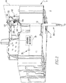
- Figures 1 and 2 show an accessory wire retention assembly 100 for an electrical switching apparatus 2 (e.g., without limitation, a circuit breaker), in accordance with a non-limiting embodiment of the disclosed concept.
- the circuit breaker 2 includes a housing 4, separable contacts 20 (shown in simplified form in Figure 2 ) and an accessory 200 (e.g., without limitation, printed circuit board (PCB)) enclosed by the housing 4.
- An operating mechanism 30 (shown in simplified form in hidden line drawing in Figure 2 ) is provided for opening and closing the separable contacts 20 ( Figure 2 ).
- a number of wires 300 are adapted to be electrically connected to the accessory 200 and, in the example shown and described herein, extend from the interior 6 of the housing 4 through an aperture 10 (shown in simplified form in hidden line drawing in Figure 2 ) to the exterior 8 of the housing 4, as best shown in Figure 2 .
- the accessory retention member 100 secures and positions a plurality of wires 300, which are bundled together and extend through the aperture 10 ( Figure 2 ) and which are electrically connected to an electrical connector 302 (best shown in Figures 1 , 5 and 6 ).
- any known or suitable alternative number and/or configuration of wires 300 could be employed, without departing from the scope of the disclosed concept.
- the accessory wire retention assembly 100 of the disclosed concept could be employed with a wide variety of different accessories (not shown) or electrical components (not shown) other than the example PCB 200.
- the example accessory wire retention assembly 100 includes an insert 102, which is structured to cooperate with the circuit breaker housing 4, and to establish the desired predetermined position of the wires 300 with respect to the accessory 200 as well as with respect to the aperture 10 of the circuit breaker housing 4.
- the accessory wire retention assembly 100 further includes a fastening mechanism 104 structured to fasten the wires 300 to the insert 102 to maintain the wires 300 in the desired predetermined position. In this manner, the accessory wire retention assembly 100 allows multiple customer accessory wires 300 to be accurately positioned and routed within the interior 6 of the circuit breaker housing 4.
- the insert 102 functions to transfer any localized pulling force on the wires 300 to the base 12 of the circuit breaker housing 4, in order that such pulling forces are not undesirably transmitted to the corresponding accessory 200.
- Establishing and maintaining accurate positioning and routing of the accessory wires 300 also minimizes the possibility of the wires 300 interfering with internal moving mechanical parts of the circuit breaker 2.
- the insert 102 of the example accessory wire retention assembly 100 is an elongated molder member 102 having a number of molded features 106,108,110,120,122,130,132,140,142.
- the molded features 106,108,110,120,122,130,132,140,142 are structured to cooperate with the housing 4, the wires 300, and the fastening mechanism 104 to establish and maintain the aforementioned desired predetermined wire position.
- the molded features include a fastening portion 106 for receiving the fastening mechanism 104 and maintaining the position of the fastening mechanism 104, as shown for example in Figure 6 .
- the fastening portion 106 preferably comprises a number of notches 108,110 (two are shown in Figure 7 ) formed in the elongated molded member 102.
- the fastening mechanism 104 in the non-limiting example shown and described herein is a wire tie 104. As shown in Figure 6 , the wire tie 104 wraps around the wires 300 with the elongated strap portion of the wire tie 104 being disposed in the molded notches 108,110. In this manner, the location of the wire tie 104 is securely fixed with respect to the insert 102. This, in turn, resists undesired movement of the wires 300.
- the example circuit breaker 2 is a molded case circuit breaker having a base 12 and a cover 14 (partially shown in simplified form in phantom line drawing in Figure 2 ) coupled to the base 12 to collectively form the housing 4.
- the aperture 10 (shown in simplified form in hidden line drawing in Figure 2 ) extends through the base 12.
- the example insert 102 also includes a guide portion 120, which is structured to cooperate with the base 12 to accurately position the insert 102 and wires 300 proximate to the accessory 200 and aperture 10, as previously discussed.
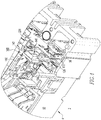
- Such guide portion 120 and corresponding guide feature of the circuit breaker base 12 can be seen, for example, in Figures 4 and 5 .
- the guide portion 120 of the example insert 102 comprises a molded flange 122 on a lateral edge of the elongated molded member 102 (see, for example, Figures 6 and 7 ).
- the circuit breaker base 12 includes a channel 50, which corresponds to the molded flange 122 such that the flange 122 is structured to be removably disposed in the channel 50.
- the insert 102 of the example accessory wire retention assembly 100 further includes a locking portion 130.
- Such locking portion 130 comprises a molded feature on the upper end of the insert 102, which is structured to cooperate with the circuit breaker cover 14, as shown in simplified form in phantom line drawing in Figure 2 .
- the locking feature comprises a molded protrusion 132 (best shown in Figures 5-7 ). More specifically, when the cover 14 (partially shown in simplified view in phantom line drawing in Figure 2 ) is installed on the base 12, a portion of the cover 14 engages at least one corresponding portion (e.g., without limitation, protrusion 132) of the insert 102 to lock the insert 102 in the desired position within the aforementioned channel 50 of the circuit breaker base 12.
- alternative locking features not shown or arrangements for cooperating with the cover 14 to lock the insert 102 in position are also contemplated by the disclosed concept.
- the insert 102 further includes a thru hole 140 extending through the elongated molded member 102, as best shown in Figure 7 .
- the wires 300 are received through the thru hole 140 to establish the aforementioned desired predetermined position of the wires 300 with respect to the circuit breaker accessory 200 (see, for example, Figures 1-5 ).
- the wires 300 are electrically connected to an electrical connector 302, which is at least partially disposed in the thru hole 140, as shown in Figures 1 , 3 , 5 and 6 .
- the example PCB 200 preferably includes a corresponding electrical connector 202, which is structured to be mechanically coupled and electrically connected to the electrical connector 302 of the accessory wires 300.
- the insert 102 of the accessory wire retention assembly 100 preferably includes a molded collar 142, which projects outwardly from the elongated molded member 102 at or about the thru hole 140, as best shown in Figure 4 .
- Such molded collar 142 functions to further align and secure the electrical connector 302 of the wires 300 in a predetermined desired orientation with respect to the electrical connector 202 of the PCB 200.
- the disclosed accessory wire retention assembly 100 provides a removable insert 102, which advantageously accurately routes accessory wires 300 to provide clearance within the interior 6 of the circuit breaker housing 4, thereby reducing the risk of the accessory wires 300 interfering with internal moving mechanical parts of the circuit breaker 2.
- the accessory wire retention assembly 100 also maintains the wires 300 in the desired position and provides wire strain relief by transferring localized stress on the wires 300 to the circuit breaker housing (e.g., base 12).
Landscapes
- Engineering & Computer Science (AREA)
- Power Engineering (AREA)
- Breakers (AREA)
- Details Of Connecting Devices For Male And Female Coupling (AREA)
Abstract
Description
- The disclosed concept relates generally to electrical switching apparatus and, more particularly, to electric switching apparatus, such as for example, circuit breakers. The disclosed concept also relates to accessory wire retention assemblies for circuit breakers.
- Electrical switching apparatus, such as circuit breakers, as well as transfer switches, network protectors and the like, are often equipped with components or accessories such as, for example and without limitation, printed circuit boards (PCB's), trip actuator assemblies, auxiliary switches, shunt trip devices, under voltage release devices, and bell alarms. Such devices can be employed in a variety of ways to provide signals indicating certain conditions within the apparatus and/or to initiate a change in status of the apparatus such as, for example, to trip open the separable contacts of the apparatus in response to an electrical fault condition (e.g., without limitation, current overload; short circuit; abnormal voltage).
- Some accessories include electrical conductors (e.g., wires). Available space within the circuit breaker housing for mounting accessories and routing the corresponding wires is limited. Wires must also be routed properly to avoid interference with internal circuit breaker components and to comply with agency code requirements, for example, with respect clearance and strain relief regulations.
- There is room for improvement in electrical switching apparatus, and in wire retention assemblies therefor.
- These needs and others are met by embodiments of the invention, which are directed to an accessory wire retention assembly for an electrical switching apparatus.
- As one aspect of the disclosed concept, an accessory wire retention assembly is provided for an electrical switching apparatus. The electrical switching apparatus comprises a housing, separable contacts and an accessory enclosed by the housing, an operating mechanism for opening and closing the separable contacts, and a number of wires adapted to be electrically connected to the accessory. The housing includes an interior, an exterior, and an aperture. The wires extend from the interior through the aperture to the exterior. The accessory wire retention assembly comprises: an insert structured to cooperate with the housing and to establish a predetermined position of the wires with respect to the accessory and the aperture; and a fastening mechanism structured to fasten the wires to the insert to maintain the wires in the predetermined position.
- The insert may be an elongated molded member comprising a number of molded features structured to cooperate with the housing, the wires, and the fastening mechanism. The molded features may include a fastening portion for receiving the fastening mechanism and maintaining the position of the fastening mechanism.
- The housing may further include a base and a cover coupled to the base, wherein the aperture extends through the base. The molded features may include a guide portion structured to cooperate with the base to accurately position the insert and the wires proximate the accessary and the aperture.
- The molded features may further include a locking portion, wherein the locking portion is structured to cooperate with the cover to lock the insert in position when the cover is installed on the base.
- The molded features may include a thru hole extending through the elongated molded member, wherein the thru hole is structured to receive the wires and position the wires in the predetermined position with respect to the accessory.
- An electrical switching apparatus employing the aforementioned accessory wire retention assembly is also disclosed.
- A full understanding of the disclosed concept can be gained from the following description of the preferred embodiments when read in conjunction with the accompanying drawings in which:
-
Figure 1 is a top isometric view of a portion of an electrical switching apparatus and accessory wire retention assembly therefor, in accordance with a non-limiting embodiment of the disclosed concept; -
Figure 2 is a bottom isometric view of the electrical switching apparatus and accessory wire retention assembly therefore ofFigure 1 , with certain features shown in hidden or phantom line drawing in simplified form; -
Figure 3 is a top front isometric view of a portion of the electrical switching apparatus and accessory wire retention assembly therefor ofFigure 2 ; -
Figure 4 is a partially exploded top back isometric view of the portion of the electrical switching apparatus and accessory wire retention assembly therefor ofFigure 3 ; -
Figure 5 is a partially exploded top front isometric view of the portion of the electrical switching apparatus and accessory wire retention assembly therefor ofFigure 4 ; -
Figure 6 is an isometric view of the accessory wire retention assembly ofFigure 5 , shown securely retaining accessory wires; and -
Figure 7 is an isometric view of a portion of the accessory wire retention assembly ofFigure 6 , shown without accessory wires. - Directional phrases used herein, such as, for example, front, back, top, bottom and derivatives thereof, relate to the orientation of the elements shown in the drawings and are not limiting upon the claims unless expressly recited therein. It is to be understood that the specific elements illustrated in the drawings and described in the following specification are simply exemplary embodiments of the disclosed concept. Therefore, specific orientations and other physical characteristics related to the embodiments disclosed herein are not to be considered limiting with respect to the scope of the disclosed concept.
- As employed herein, the singular form of "a", "an", and "the" include plural references unless the context clearly dictates otherwise. Still further, as used herein, the term "number" shall mean one or an integer greater than one (e.g., a plurality).
- As employed herein, the term "coupled" shall mean that two or more parts are joined together directly or joined through one or more intermediate parts. Furthermore, as employed herein, the phrase "directly connected" shall mean that two or more parts are joined together directly, without any intermediate parts being disposed therebetween at the point or location of the connection.
- As employed herein, the phrase "electrically connected" shall mean that two or more parts or components are joined together either directly or joined through one or more intermediate parts such that electricity, current, voltage, and/or energy is operable to flow from one part or component to the other part or component, and vice versa.
- As employed herein, the term "accessory" refers to any known or suitable component or feature of an electrical switching apparatus and expressly includes, but is not limited to, printed circuit boards (PCB's), trip actuators, auxiliary switches, shunt trip devices, under voltage release devices, and bell alarms.
-
Figures 1 and2 show an accessorywire retention assembly 100 for an electrical switching apparatus 2 (e.g., without limitation, a circuit breaker), in accordance with a non-limiting embodiment of the disclosed concept. In the example shown and described herein, thecircuit breaker 2 includes a housing 4, separable contacts 20 (shown in simplified form inFigure 2 ) and an accessory 200 (e.g., without limitation, printed circuit board (PCB)) enclosed by the housing 4. An operating mechanism 30 (shown in simplified form in hidden line drawing inFigure 2 ) is provided for opening and closing the separable contacts 20 (Figure 2 ). A number ofwires 300 are adapted to be electrically connected to theaccessory 200 and, in the example shown and described herein, extend from the interior 6 of the housing 4 through an aperture 10 (shown in simplified form in hidden line drawing inFigure 2 ) to theexterior 8 of the housing 4, as best shown inFigure 2 . In the example shown and described, theaccessory retention member 100 secures and positions a plurality ofwires 300, which are bundled together and extend through the aperture 10 (Figure 2 ) and which are electrically connected to an electrical connector 302 (best shown inFigures 1 ,5 and 6 ). It will be appreciated, however, that any known or suitable alternative number and/or configuration ofwires 300 could be employed, without departing from the scope of the disclosed concept. It will further be appreciated that the accessorywire retention assembly 100 of the disclosed concept could be employed with a wide variety of different accessories (not shown) or electrical components (not shown) other than theexample PCB 200. - Continuing to refer to
Figures 1 and2 , as well asFigures 3-5 , it will be appreciated that the example accessorywire retention assembly 100 includes aninsert 102, which is structured to cooperate with the circuit breaker housing 4, and to establish the desired predetermined position of thewires 300 with respect to theaccessory 200 as well as with respect to theaperture 10 of the circuit breaker housing 4. The accessorywire retention assembly 100 further includes afastening mechanism 104 structured to fasten thewires 300 to theinsert 102 to maintain thewires 300 in the desired predetermined position. In this manner, the accessorywire retention assembly 100 allows multiplecustomer accessory wires 300 to be accurately positioned and routed within the interior 6 of the circuit breaker housing 4. Additionally, among other benefits, theinsert 102 functions to transfer any localized pulling force on thewires 300 to thebase 12 of the circuit breaker housing 4, in order that such pulling forces are not undesirably transmitted to thecorresponding accessory 200. Establishing and maintaining accurate positioning and routing of theaccessory wires 300 also minimizes the possibility of thewires 300 interfering with internal moving mechanical parts of thecircuit breaker 2. - As best shown in
Figures 5-7 , theinsert 102 of the example accessorywire retention assembly 100 is anelongated molder member 102 having a number of molded features 106,108,110,120,122,130,132,140,142. As will be discussed, the molded features 106,108,110,120,122,130,132,140,142 are structured to cooperate with the housing 4, thewires 300, and thefastening mechanism 104 to establish and maintain the aforementioned desired predetermined wire position. The molded features include afastening portion 106 for receiving thefastening mechanism 104 and maintaining the position of thefastening mechanism 104, as shown for example inFigure 6 . Thefastening portion 106 preferably comprises a number of notches 108,110 (two are shown inFigure 7 ) formed in the elongated moldedmember 102. Thefastening mechanism 104 in the non-limiting example shown and described herein is awire tie 104. As shown inFigure 6 , thewire tie 104 wraps around thewires 300 with the elongated strap portion of thewire tie 104 being disposed in the molded notches 108,110. In this manner, the location of thewire tie 104 is securely fixed with respect to theinsert 102. This, in turn, resists undesired movement of thewires 300. - The
example circuit breaker 2 is a molded case circuit breaker having abase 12 and a cover 14 (partially shown in simplified form in phantom line drawing inFigure 2 ) coupled to thebase 12 to collectively form the housing 4. The aperture 10 (shown in simplified form in hidden line drawing inFigure 2 ) extends through thebase 12. Among other molded features, theexample insert 102 also includes aguide portion 120, which is structured to cooperate with the base 12 to accurately position theinsert 102 andwires 300 proximate to theaccessory 200 andaperture 10, as previously discussed.Such guide portion 120 and corresponding guide feature of thecircuit breaker base 12 can be seen, for example, inFigures 4 and5 . More specifically, as best shown in the exploded views ofFigures 4 and5 , theguide portion 120 of theexample insert 102 comprises a moldedflange 122 on a lateral edge of the elongated molded member 102 (see, for example,Figures 6 and 7 ). Thecircuit breaker base 12 includes achannel 50, which corresponds to the moldedflange 122 such that theflange 122 is structured to be removably disposed in thechannel 50. This will be further appreciated with reference to and comparison of the exploded views ofFigures 4 and5 , and the assembled or installed views ofFigures 1 and3 . - The
insert 102 of the example accessorywire retention assembly 100 further includes a lockingportion 130.Such locking portion 130 comprises a molded feature on the upper end of theinsert 102, which is structured to cooperate with the circuit breaker cover 14, as shown in simplified form in phantom line drawing inFigure 2 . In the example showing and described herein, the locking feature comprises a molded protrusion 132 (best shown inFigures 5-7 ). More specifically, when the cover 14 (partially shown in simplified view in phantom line drawing inFigure 2 ) is installed on thebase 12, a portion of the cover 14 engages at least one corresponding portion (e.g., without limitation, protrusion 132) of theinsert 102 to lock theinsert 102 in the desired position within theaforementioned channel 50 of thecircuit breaker base 12. Although, it will be appreciated that alternative locking features (not shown) or arrangements for cooperating with the cover 14 to lock theinsert 102 in position are also contemplated by the disclosed concept. - The
insert 102 further includes a thruhole 140 extending through the elongated moldedmember 102, as best shown inFigure 7 . Thewires 300 are received through the thruhole 140 to establish the aforementioned desired predetermined position of thewires 300 with respect to the circuit breaker accessory 200 (see, for example,Figures 1-5 ). As previously noted, in the non-limiting example shown and described herein, thewires 300 are electrically connected to anelectrical connector 302, which is at least partially disposed in the thruhole 140, as shown inFigures 1 ,3 ,5 and 6 . As shown inFigure 5 , theexample PCB 200 preferably includes a corresponding electrical connector 202, which is structured to be mechanically coupled and electrically connected to theelectrical connector 302 of theaccessory wires 300. Theinsert 102 of the accessorywire retention assembly 100 preferably includes a moldedcollar 142, which projects outwardly from the elongated moldedmember 102 at or about the thruhole 140, as best shown inFigure 4 . Such moldedcollar 142 functions to further align and secure theelectrical connector 302 of thewires 300 in a predetermined desired orientation with respect to the electrical connector 202 of thePCB 200. - Accordingly, the disclosed accessory
wire retention assembly 100 provides aremovable insert 102, which advantageously accurately routesaccessory wires 300 to provide clearance within the interior 6 of the circuit breaker housing 4, thereby reducing the risk of theaccessory wires 300 interfering with internal moving mechanical parts of thecircuit breaker 2. In addition to establishing consistent, accurate and reliable placement ofcustomer wires 300 with respect tocircuit breaker accessories 200, the accessorywire retention assembly 100 also maintains thewires 300 in the desired position and provides wire strain relief by transferring localized stress on thewires 300 to the circuit breaker housing (e.g., base 12). - While specific embodiments of the disclosed concept have been described in detail, it will be appreciated by those skilled in the art that various modifications and alternatives to those details could be developed in light of the overall teachings of the disclosure. Accordingly, the particular arrangements disclosed are meant to be illustrative only and not limiting as to the scope of the disclosed concept which is to be given the full breadth of the claims appended and any and all equivalents thereof.
Claims (12)
- An accessory wire retention assembly for an electrical switching apparatus, said electrical switching apparatus comprising a housing, separable contacts and an accessory enclosed by the housing, an operating mechanism for opening and closing said separable contacts, and a number of wires adapted to be electrically connected to said accessory, the housing including an interior, an exterior, and an aperture, said wires extending from the interior through said aperture to the exterior, said accessory wire retention assembly comprising:an insert structured to cooperate with the housing and to establish a predetermined position of said wires with respect to said accessory and said aperture; anda fastening mechanism structured to fasten said wires to said insert to maintain said wires in said predetermined position.
- The accessory wire retention assembly of claim 1 wherein said insert is an elongated molded member comprising a number of molded features structured to cooperate with the housing, said wires, and said fastening mechanism.
- The accessory wire retention assembly of claim 2 wherein said number of molded features includes a fastening portion for receiving said fastening mechanism and maintaining the position of said fastening mechanism.
- The accessory wire retention assembly of claim 3 wherein said fastening portion comprises a number of notches formed in said elongated molded member; wherein said fastening mechanism is a wire tie; and wherein said wire tie is structured to wrap around said wires and be disposed in said number of molded notches to resist undesired movement of said wires.
- The accessory wire retention assembly of claim 2 wherein said housing further includes a base and a cover coupled to said base; wherein said aperture extends through said base; and wherein said number of molded features includes a guide portion structured to cooperate with said base to accurately position said insert and said wires proximate said accessary and said aperture.
- The accessory wire retention assembly of claim 5 wherein said guide portion comprises a molded flange; wherein said base includes a channel corresponding to said molded flange; and wherein said flange is structured to be removably disposed in said channel.
- The accessory wire retention assembly of claim 5 wherein said number of molded features further includes a locking portion; and wherein said locking portion is structured to cooperate with said cover to lock said insert in position when said cover is installed on said base.
- The accessory wire retention assembly of claim 2 wherein said number of molded features includes a thru hole extending through said elongated molded member; and wherein said thru hole is structured to receive said wires and position said wires in said predetermined position with respect to said accessory.
- The accessory wire retention assembly of claim 8 further comprising an electrical connector electrically connected to said wires; and wherein said electrical connector is at least partially disposed in said thru hole.
- The accessory wire retention assembly of claim 9 wherein said accessory comprises a printed circuit board; wherein said printed circuit board includes an electrical connector structured to be mechanically coupled and electrically connected to said electrical connector of said wires; wherein said insert further comprises a molded collar projecting outwardly from said elongated molded member at or about said thru hole; and wherein said molded collar is structured to align and secure said electrical connector of said wires in a predetermined orientation with respect to said electrical connector of said printed circuit board.
- An electrical switching apparatus comprising:a housing including an interior, an exterior, and an aperture;separable contacts enclosed by the housing;an accessory enclosed by the housing;an operating mechanism for opening and closing said separable contacts;a number of wires adapted to be electrically connected to said accessory, said wires extending from the interior of the housing through said aperture to the exterior of the housing; andan accessory wire retention assembly according to any of claims 1-10.
- The electrical switching apparatus of claim 11 wherein said electrical switching apparatus is a circuit breaker.
Applications Claiming Priority (1)
| Application Number | Priority Date | Filing Date | Title |
|---|---|---|---|
| US15/671,279 US10431409B2 (en) | 2017-08-08 | 2017-08-08 | Electrical switching apparatus and accessory wire retention assembly therefor |
Publications (2)
| Publication Number | Publication Date |
|---|---|
| EP3462473A1 true EP3462473A1 (en) | 2019-04-03 |
| EP3462473B1 EP3462473B1 (en) | 2022-05-18 |
Family
ID=63144843
Family Applications (1)
| Application Number | Title | Priority Date | Filing Date |
|---|---|---|---|
| EP18187155.9A Active EP3462473B1 (en) | 2017-08-08 | 2018-08-02 | Electrical switching apparatus and accessory wire retention assembly therefore |
Country Status (2)
| Country | Link |
|---|---|
| US (1) | US10431409B2 (en) |
| EP (1) | EP3462473B1 (en) |
Citations (6)
| Publication number | Priority date | Publication date | Assignee | Title |
|---|---|---|---|---|
| US4408174A (en) * | 1981-12-14 | 1983-10-04 | General Electric Co. | Accessory mounting module for J and K frame breakers |
| JPS6212240U (en) * | 1985-07-08 | 1987-01-24 | ||
| DE4408234C1 (en) * | 1994-03-11 | 1995-06-14 | Kloeckner Moeller Gmbh | Housing with accessories for power switch |
| JPH1012118A (en) * | 1996-06-21 | 1998-01-16 | Mitsubishi Electric Corp | Circuit breaker |
| FR2994346A1 (en) * | 2012-08-06 | 2014-02-07 | Legrand France | Modular cap assembly for lodging of e.g. electric modules, has adapter that is positioned in opening of cap, where adapter partially wraps connection block, and fixing unit such as slides, of connection block is arranged on adapter |
| DE102013209773A1 (en) * | 2013-05-27 | 2014-11-27 | Siemens Aktiengesellschaft | Device, in particular residual current circuit breaker |
Family Cites Families (17)
| Publication number | Priority date | Publication date | Assignee | Title |
|---|---|---|---|---|
| US6816049B2 (en) * | 2002-09-19 | 2004-11-09 | Fuji Xerox Co., Ltd. | Actuator |
| US7800468B2 (en) * | 2007-03-28 | 2010-09-21 | Eaton Corporation | Electrical switching apparatus, and accessory module and strain relief mechanism therefor |
| JP5471393B2 (en) * | 2009-12-11 | 2014-04-16 | 株式会社日本自動車部品総合研究所 | Input device |
| JP2014217176A (en) * | 2013-04-25 | 2014-11-17 | 株式会社デンソー | Input device |
| JP5900408B2 (en) * | 2013-05-07 | 2016-04-06 | 株式会社デンソー | Operating device |
| JP5983545B2 (en) * | 2013-06-26 | 2016-08-31 | 株式会社デンソー | Input device |
| JP6098438B2 (en) * | 2013-08-27 | 2017-03-22 | 株式会社デンソー | Operating device |
| JP6187161B2 (en) * | 2013-10-30 | 2017-08-30 | 株式会社デンソー | Input device |
| JP6167893B2 (en) * | 2013-12-26 | 2017-07-26 | 株式会社デンソー | Input device |
| JP6112021B2 (en) * | 2014-01-09 | 2017-04-12 | 株式会社デンソー | Input device |
| US9443686B2 (en) | 2014-03-27 | 2016-09-13 | Eaton Corporation | Trip unit strain relief |
| JP6464927B2 (en) * | 2015-03-03 | 2019-02-06 | 株式会社Soken | Input device |
| JP6458568B2 (en) * | 2015-03-11 | 2019-01-30 | 株式会社デンソー | Input device |
| JP6681579B2 (en) * | 2015-07-01 | 2020-04-15 | パナソニックIpマネジメント株式会社 | Electromagnet device and electromagnetic relay using the same |
| JP6667257B2 (en) * | 2015-10-28 | 2020-03-18 | アンデン株式会社 | Electromagnetic relay |
| JP6132043B1 (en) * | 2016-02-23 | 2017-05-24 | オムロン株式会社 | Power switchgear |
| CN108292575A (en) * | 2016-06-14 | 2018-07-17 | 富士电机机器制御株式会社 | Contact making device and utilize its electromagnetic contactor |
-
2017
- 2017-08-08 US US15/671,279 patent/US10431409B2/en active Active
-
2018
- 2018-08-02 EP EP18187155.9A patent/EP3462473B1/en active Active
Patent Citations (6)
| Publication number | Priority date | Publication date | Assignee | Title |
|---|---|---|---|---|
| US4408174A (en) * | 1981-12-14 | 1983-10-04 | General Electric Co. | Accessory mounting module for J and K frame breakers |
| JPS6212240U (en) * | 1985-07-08 | 1987-01-24 | ||
| DE4408234C1 (en) * | 1994-03-11 | 1995-06-14 | Kloeckner Moeller Gmbh | Housing with accessories for power switch |
| JPH1012118A (en) * | 1996-06-21 | 1998-01-16 | Mitsubishi Electric Corp | Circuit breaker |
| FR2994346A1 (en) * | 2012-08-06 | 2014-02-07 | Legrand France | Modular cap assembly for lodging of e.g. electric modules, has adapter that is positioned in opening of cap, where adapter partially wraps connection block, and fixing unit such as slides, of connection block is arranged on adapter |
| DE102013209773A1 (en) * | 2013-05-27 | 2014-11-27 | Siemens Aktiengesellschaft | Device, in particular residual current circuit breaker |
Also Published As
| Publication number | Publication date |
|---|---|
| EP3462473B1 (en) | 2022-05-18 |
| US20190051482A1 (en) | 2019-02-14 |
| US10431409B2 (en) | 2019-10-01 |
Similar Documents
| Publication | Publication Date | Title |
|---|---|---|
| US4912439A (en) | Molded case circuit breaker auxiliary switch unit | |
| EP1975963B1 (en) | Electrical switching apparatus and accessory assembly therefor | |
| EP1975964B1 (en) | Electrical switching apparatus and accessory module and strain relief mechanism therefor | |
| EP1975955B1 (en) | Electrical switching apparatus and accessory tray therefor | |
| EP1975965B1 (en) | Electrical switching apparatus, and accessory module and electrical conductor mount therefor | |
| US7385153B1 (en) | Electrical switching apparatus and trip bar therefor | |
| CA2626986C (en) | Electrical switching apparatus, and sub-assembly and auxiliary switch tray therefor | |
| US10431409B2 (en) | Electrical switching apparatus and accessory wire retention assembly therefor | |
| CN111725035B (en) | Quick-connect terminal blocks and circuit breakers | |
| US7961480B2 (en) | Device for housing and connection of accessories for switches | |
| KR102071551B1 (en) | Electronic Trip Device of Molded Case Circuit Breaker |
Legal Events
| Date | Code | Title | Description |
|---|---|---|---|
| PUAI | Public reference made under article 153(3) epc to a published international application that has entered the european phase |
Free format text: ORIGINAL CODE: 0009012 |
|
| STAA | Information on the status of an ep patent application or granted ep patent |
Free format text: STATUS: REQUEST FOR EXAMINATION WAS MADE |
|
| 17P | Request for examination filed |
Effective date: 20180802 |
|
| AK | Designated contracting states |
Kind code of ref document: A1 Designated state(s): AL AT BE BG CH CY CZ DE DK EE ES FI FR GB GR HR HU IE IS IT LI LT LU LV MC MK MT NL NO PL PT RO RS SE SI SK SM TR |
|
| AX | Request for extension of the european patent |
Extension state: BA ME |
|
| STAA | Information on the status of an ep patent application or granted ep patent |
Free format text: STATUS: EXAMINATION IS IN PROGRESS |
|
| 17Q | First examination report despatched |
Effective date: 20200703 |
|
| GRAP | Despatch of communication of intention to grant a patent |
Free format text: ORIGINAL CODE: EPIDOSNIGR1 |
|
| STAA | Information on the status of an ep patent application or granted ep patent |
Free format text: STATUS: GRANT OF PATENT IS INTENDED |
|
| INTG | Intention to grant announced |
Effective date: 20210914 |
|
| GRAS | Grant fee paid |
Free format text: ORIGINAL CODE: EPIDOSNIGR3 |
|
| GRAA | (expected) grant |
Free format text: ORIGINAL CODE: 0009210 |
|
| STAA | Information on the status of an ep patent application or granted ep patent |
Free format text: STATUS: THE PATENT HAS BEEN GRANTED |
|
| AK | Designated contracting states |
Kind code of ref document: B1 Designated state(s): AL AT BE BG CH CY CZ DE DK EE ES FI FR GB GR HR HU IE IS IT LI LT LU LV MC MK MT NL NO PL PT RO RS SE SI SK SM TR |
|
| REG | Reference to a national code |
Ref country code: GB Ref legal event code: FG4D |
|
| REG | Reference to a national code |
Ref country code: CH Ref legal event code: EP |
|
| REG | Reference to a national code |
Ref country code: IE Ref legal event code: FG4D |
|
| REG | Reference to a national code |
Ref country code: DE Ref legal event code: R096 Ref document number: 602018035692 Country of ref document: DE |
|
| REG | Reference to a national code |
Ref country code: AT Ref legal event code: REF Ref document number: 1493622 Country of ref document: AT Kind code of ref document: T Effective date: 20220615 |
|
| REG | Reference to a national code |
Ref country code: LT Ref legal event code: MG9D |
|
| REG | Reference to a national code |
Ref country code: NL Ref legal event code: MP Effective date: 20220518 |
|
| REG | Reference to a national code |
Ref country code: AT Ref legal event code: MK05 Ref document number: 1493622 Country of ref document: AT Kind code of ref document: T Effective date: 20220518 |
|
| PG25 | Lapsed in a contracting state [announced via postgrant information from national office to epo] |
Ref country code: SE Free format text: LAPSE BECAUSE OF FAILURE TO SUBMIT A TRANSLATION OF THE DESCRIPTION OR TO PAY THE FEE WITHIN THE PRESCRIBED TIME-LIMIT Effective date: 20220518 Ref country code: PT Free format text: LAPSE BECAUSE OF FAILURE TO SUBMIT A TRANSLATION OF THE DESCRIPTION OR TO PAY THE FEE WITHIN THE PRESCRIBED TIME-LIMIT Effective date: 20220919 Ref country code: NO Free format text: LAPSE BECAUSE OF FAILURE TO SUBMIT A TRANSLATION OF THE DESCRIPTION OR TO PAY THE FEE WITHIN THE PRESCRIBED TIME-LIMIT Effective date: 20220818 Ref country code: NL Free format text: LAPSE BECAUSE OF FAILURE TO SUBMIT A TRANSLATION OF THE DESCRIPTION OR TO PAY THE FEE WITHIN THE PRESCRIBED TIME-LIMIT Effective date: 20220518 Ref country code: LT Free format text: LAPSE BECAUSE OF FAILURE TO SUBMIT A TRANSLATION OF THE DESCRIPTION OR TO PAY THE FEE WITHIN THE PRESCRIBED TIME-LIMIT Effective date: 20220518 Ref country code: HR Free format text: LAPSE BECAUSE OF FAILURE TO SUBMIT A TRANSLATION OF THE DESCRIPTION OR TO PAY THE FEE WITHIN THE PRESCRIBED TIME-LIMIT Effective date: 20220518 Ref country code: GR Free format text: LAPSE BECAUSE OF FAILURE TO SUBMIT A TRANSLATION OF THE DESCRIPTION OR TO PAY THE FEE WITHIN THE PRESCRIBED TIME-LIMIT Effective date: 20220819 Ref country code: FI Free format text: LAPSE BECAUSE OF FAILURE TO SUBMIT A TRANSLATION OF THE DESCRIPTION OR TO PAY THE FEE WITHIN THE PRESCRIBED TIME-LIMIT Effective date: 20220518 Ref country code: ES Free format text: LAPSE BECAUSE OF FAILURE TO SUBMIT A TRANSLATION OF THE DESCRIPTION OR TO PAY THE FEE WITHIN THE PRESCRIBED TIME-LIMIT Effective date: 20220518 Ref country code: BG Free format text: LAPSE BECAUSE OF FAILURE TO SUBMIT A TRANSLATION OF THE DESCRIPTION OR TO PAY THE FEE WITHIN THE PRESCRIBED TIME-LIMIT Effective date: 20220818 Ref country code: AT Free format text: LAPSE BECAUSE OF FAILURE TO SUBMIT A TRANSLATION OF THE DESCRIPTION OR TO PAY THE FEE WITHIN THE PRESCRIBED TIME-LIMIT Effective date: 20220518 |
|
| PG25 | Lapsed in a contracting state [announced via postgrant information from national office to epo] |
Ref country code: RS Free format text: LAPSE BECAUSE OF FAILURE TO SUBMIT A TRANSLATION OF THE DESCRIPTION OR TO PAY THE FEE WITHIN THE PRESCRIBED TIME-LIMIT Effective date: 20220518 Ref country code: PL Free format text: LAPSE BECAUSE OF FAILURE TO SUBMIT A TRANSLATION OF THE DESCRIPTION OR TO PAY THE FEE WITHIN THE PRESCRIBED TIME-LIMIT Effective date: 20220518 Ref country code: LV Free format text: LAPSE BECAUSE OF FAILURE TO SUBMIT A TRANSLATION OF THE DESCRIPTION OR TO PAY THE FEE WITHIN THE PRESCRIBED TIME-LIMIT Effective date: 20220518 Ref country code: IS Free format text: LAPSE BECAUSE OF FAILURE TO SUBMIT A TRANSLATION OF THE DESCRIPTION OR TO PAY THE FEE WITHIN THE PRESCRIBED TIME-LIMIT Effective date: 20220918 |
|
| PG25 | Lapsed in a contracting state [announced via postgrant information from national office to epo] |
Ref country code: SM Free format text: LAPSE BECAUSE OF FAILURE TO SUBMIT A TRANSLATION OF THE DESCRIPTION OR TO PAY THE FEE WITHIN THE PRESCRIBED TIME-LIMIT Effective date: 20220518 Ref country code: SK Free format text: LAPSE BECAUSE OF FAILURE TO SUBMIT A TRANSLATION OF THE DESCRIPTION OR TO PAY THE FEE WITHIN THE PRESCRIBED TIME-LIMIT Effective date: 20220518 Ref country code: RO Free format text: LAPSE BECAUSE OF FAILURE TO SUBMIT A TRANSLATION OF THE DESCRIPTION OR TO PAY THE FEE WITHIN THE PRESCRIBED TIME-LIMIT Effective date: 20220518 Ref country code: EE Free format text: LAPSE BECAUSE OF FAILURE TO SUBMIT A TRANSLATION OF THE DESCRIPTION OR TO PAY THE FEE WITHIN THE PRESCRIBED TIME-LIMIT Effective date: 20220518 Ref country code: DK Free format text: LAPSE BECAUSE OF FAILURE TO SUBMIT A TRANSLATION OF THE DESCRIPTION OR TO PAY THE FEE WITHIN THE PRESCRIBED TIME-LIMIT Effective date: 20220518 Ref country code: CZ Free format text: LAPSE BECAUSE OF FAILURE TO SUBMIT A TRANSLATION OF THE DESCRIPTION OR TO PAY THE FEE WITHIN THE PRESCRIBED TIME-LIMIT Effective date: 20220518 |
|
| REG | Reference to a national code |
Ref country code: DE Ref legal event code: R097 Ref document number: 602018035692 Country of ref document: DE |
|
| PLBE | No opposition filed within time limit |
Free format text: ORIGINAL CODE: 0009261 |
|
| STAA | Information on the status of an ep patent application or granted ep patent |
Free format text: STATUS: NO OPPOSITION FILED WITHIN TIME LIMIT |
|
| PG25 | Lapsed in a contracting state [announced via postgrant information from national office to epo] |
Ref country code: MC Free format text: LAPSE BECAUSE OF FAILURE TO SUBMIT A TRANSLATION OF THE DESCRIPTION OR TO PAY THE FEE WITHIN THE PRESCRIBED TIME-LIMIT Effective date: 20220518 Ref country code: AL Free format text: LAPSE BECAUSE OF FAILURE TO SUBMIT A TRANSLATION OF THE DESCRIPTION OR TO PAY THE FEE WITHIN THE PRESCRIBED TIME-LIMIT Effective date: 20220518 |
|
| REG | Reference to a national code |
Ref country code: CH Ref legal event code: PL |
|
| 26N | No opposition filed |
Effective date: 20230221 |
|
| GBPC | Gb: european patent ceased through non-payment of renewal fee |
Effective date: 20220818 |
|
| PG25 | Lapsed in a contracting state [announced via postgrant information from national office to epo] |
Ref country code: LI Free format text: LAPSE BECAUSE OF NON-PAYMENT OF DUE FEES Effective date: 20220831 Ref country code: CH Free format text: LAPSE BECAUSE OF NON-PAYMENT OF DUE FEES Effective date: 20220831 Ref country code: LU Free format text: LAPSE BECAUSE OF NON-PAYMENT OF DUE FEES Effective date: 20220802 |
|
| REG | Reference to a national code |
Ref country code: BE Ref legal event code: MM Effective date: 20220831 |
|
| PG25 | Lapsed in a contracting state [announced via postgrant information from national office to epo] |
Ref country code: SI Free format text: LAPSE BECAUSE OF FAILURE TO SUBMIT A TRANSLATION OF THE DESCRIPTION OR TO PAY THE FEE WITHIN THE PRESCRIBED TIME-LIMIT Effective date: 20220518 |
|
| P01 | Opt-out of the competence of the unified patent court (upc) registered |
Effective date: 20230521 |
|
| PG25 | Lapsed in a contracting state [announced via postgrant information from national office to epo] |
Ref country code: IE Free format text: LAPSE BECAUSE OF NON-PAYMENT OF DUE FEES Effective date: 20220802 |
|
| PG25 | Lapsed in a contracting state [announced via postgrant information from national office to epo] |
Ref country code: BE Free format text: LAPSE BECAUSE OF NON-PAYMENT OF DUE FEES Effective date: 20220831 |
|
| PG25 | Lapsed in a contracting state [announced via postgrant information from national office to epo] |
Ref country code: GB Free format text: LAPSE BECAUSE OF NON-PAYMENT OF DUE FEES Effective date: 20220818 |
|
| PG25 | Lapsed in a contracting state [announced via postgrant information from national office to epo] |
Ref country code: HU Free format text: LAPSE BECAUSE OF FAILURE TO SUBMIT A TRANSLATION OF THE DESCRIPTION OR TO PAY THE FEE WITHIN THE PRESCRIBED TIME-LIMIT; INVALID AB INITIO Effective date: 20180802 |
|
| PG25 | Lapsed in a contracting state [announced via postgrant information from national office to epo] |
Ref country code: MK Free format text: LAPSE BECAUSE OF FAILURE TO SUBMIT A TRANSLATION OF THE DESCRIPTION OR TO PAY THE FEE WITHIN THE PRESCRIBED TIME-LIMIT Effective date: 20220511 Ref country code: CY Free format text: LAPSE BECAUSE OF FAILURE TO SUBMIT A TRANSLATION OF THE DESCRIPTION OR TO PAY THE FEE WITHIN THE PRESCRIBED TIME-LIMIT Effective date: 20220511 |
|
| PG25 | Lapsed in a contracting state [announced via postgrant information from national office to epo] |
Ref country code: MT Free format text: LAPSE BECAUSE OF FAILURE TO SUBMIT A TRANSLATION OF THE DESCRIPTION OR TO PAY THE FEE WITHIN THE PRESCRIBED TIME-LIMIT Effective date: 20220511 |
|
| PG25 | Lapsed in a contracting state [announced via postgrant information from national office to epo] |
Ref country code: BG Free format text: LAPSE BECAUSE OF FAILURE TO SUBMIT A TRANSLATION OF THE DESCRIPTION OR TO PAY THE FEE WITHIN THE PRESCRIBED TIME-LIMIT Effective date: 20220518 |
|
| PG25 | Lapsed in a contracting state [announced via postgrant information from national office to epo] |
Ref country code: BG Free format text: LAPSE BECAUSE OF FAILURE TO SUBMIT A TRANSLATION OF THE DESCRIPTION OR TO PAY THE FEE WITHIN THE PRESCRIBED TIME-LIMIT Effective date: 20220518 |
|
| PGFP | Annual fee paid to national office [announced via postgrant information from national office to epo] |
Ref country code: DE Payment date: 20250724 Year of fee payment: 8 |
|
| PGFP | Annual fee paid to national office [announced via postgrant information from national office to epo] |
Ref country code: IT Payment date: 20250723 Year of fee payment: 8 |
|
| PGFP | Annual fee paid to national office [announced via postgrant information from national office to epo] |
Ref country code: FR Payment date: 20250725 Year of fee payment: 8 |
|
| PG25 | Lapsed in a contracting state [announced via postgrant information from national office to epo] |
Ref country code: TR Free format text: LAPSE BECAUSE OF FAILURE TO SUBMIT A TRANSLATION OF THE DESCRIPTION OR TO PAY THE FEE WITHIN THE PRESCRIBED TIME-LIMIT Effective date: 20220518 |