EP3461999A1 - Konturierte gehäusebuckel für einen gasturbinenmotor - Google Patents
Konturierte gehäusebuckel für einen gasturbinenmotor Download PDFInfo
- Publication number
- EP3461999A1 EP3461999A1 EP18196957.7A EP18196957A EP3461999A1 EP 3461999 A1 EP3461999 A1 EP 3461999A1 EP 18196957 A EP18196957 A EP 18196957A EP 3461999 A1 EP3461999 A1 EP 3461999A1
- Authority
- EP
- European Patent Office
- Prior art keywords
- case
- boss
- thickness
- wall
- gas turbine
- Prior art date
- Legal status (The legal status is an assumption and is not a legal conclusion. Google has not performed a legal analysis and makes no representation as to the accuracy of the status listed.)
- Withdrawn
Links
Images


Classifications
-
- F—MECHANICAL ENGINEERING; LIGHTING; HEATING; WEAPONS; BLASTING
- F01—MACHINES OR ENGINES IN GENERAL; ENGINE PLANTS IN GENERAL; STEAM ENGINES
- F01D—NON-POSITIVE DISPLACEMENT MACHINES OR ENGINES, e.g. STEAM TURBINES
- F01D25/00—Component parts, details, or accessories, not provided for in, or of interest apart from, other groups
- F01D25/08—Cooling; Heating; Heat-insulation
- F01D25/14—Casings modified therefor
-
- F—MECHANICAL ENGINEERING; LIGHTING; HEATING; WEAPONS; BLASTING
- F01—MACHINES OR ENGINES IN GENERAL; ENGINE PLANTS IN GENERAL; STEAM ENGINES
- F01D—NON-POSITIVE DISPLACEMENT MACHINES OR ENGINES, e.g. STEAM TURBINES
- F01D21/00—Shutting-down of machines or engines, e.g. in emergency; Regulating, controlling, or safety means not otherwise provided for
- F01D21/003—Arrangements for testing or measuring
-
- F—MECHANICAL ENGINEERING; LIGHTING; HEATING; WEAPONS; BLASTING
- F01—MACHINES OR ENGINES IN GENERAL; ENGINE PLANTS IN GENERAL; STEAM ENGINES
- F01D—NON-POSITIVE DISPLACEMENT MACHINES OR ENGINES, e.g. STEAM TURBINES
- F01D25/00—Component parts, details, or accessories, not provided for in, or of interest apart from, other groups
- F01D25/24—Casings; Casing parts, e.g. diaphragms, casing fastenings
-
- F—MECHANICAL ENGINEERING; LIGHTING; HEATING; WEAPONS; BLASTING
- F02—COMBUSTION ENGINES; HOT-GAS OR COMBUSTION-PRODUCT ENGINE PLANTS
- F02C—GAS-TURBINE PLANTS; AIR INTAKES FOR JET-PROPULSION PLANTS; CONTROLLING FUEL SUPPLY IN AIR-BREATHING JET-PROPULSION PLANTS
- F02C7/00—Features, components parts, details or accessories, not provided for in, or of interest apart form groups F02C1/00 - F02C6/00; Air intakes for jet-propulsion plants
- F02C7/12—Cooling of plants
-
- F—MECHANICAL ENGINEERING; LIGHTING; HEATING; WEAPONS; BLASTING
- F04—POSITIVE - DISPLACEMENT MACHINES FOR LIQUIDS; PUMPS FOR LIQUIDS OR ELASTIC FLUIDS
- F04D—NON-POSITIVE-DISPLACEMENT PUMPS
- F04D29/00—Details, component parts, or accessories
- F04D29/58—Cooling; Heating; Diminishing heat transfer
- F04D29/582—Cooling; Heating; Diminishing heat transfer specially adapted for elastic fluid pumps
- F04D29/5853—Cooling; Heating; Diminishing heat transfer specially adapted for elastic fluid pumps heat insulation or conduction
-
- F—MECHANICAL ENGINEERING; LIGHTING; HEATING; WEAPONS; BLASTING
- F23—COMBUSTION APPARATUS; COMBUSTION PROCESSES
- F23M—CASINGS, LININGS, WALLS OR DOORS SPECIALLY ADAPTED FOR COMBUSTION CHAMBERS, e.g. FIREBRIDGES; DEVICES FOR DEFLECTING AIR, FLAMES OR COMBUSTION PRODUCTS IN COMBUSTION CHAMBERS; SAFETY ARRANGEMENTS SPECIALLY ADAPTED FOR COMBUSTION APPARATUS; DETAILS OF COMBUSTION CHAMBERS, NOT OTHERWISE PROVIDED FOR
- F23M11/00—Safety arrangements
- F23M11/04—Means for supervising combustion, e.g. windows
-
- F—MECHANICAL ENGINEERING; LIGHTING; HEATING; WEAPONS; BLASTING
- F23—COMBUSTION APPARATUS; COMBUSTION PROCESSES
- F23R—GENERATING COMBUSTION PRODUCTS OF HIGH PRESSURE OR HIGH VELOCITY, e.g. GAS-TURBINE COMBUSTION CHAMBERS
- F23R3/00—Continuous combustion chambers using liquid or gaseous fuel
- F23R3/002—Wall structures
-
- F—MECHANICAL ENGINEERING; LIGHTING; HEATING; WEAPONS; BLASTING
- F05—INDEXING SCHEMES RELATING TO ENGINES OR PUMPS IN VARIOUS SUBCLASSES OF CLASSES F01-F04
- F05D—INDEXING SCHEME FOR ASPECTS RELATING TO NON-POSITIVE-DISPLACEMENT MACHINES OR ENGINES, GAS-TURBINES OR JET-PROPULSION PLANTS
- F05D2230/00—Manufacture
- F05D2230/50—Building or constructing in particular ways
- F05D2230/53—Building or constructing in particular ways by integrally manufacturing a component, e.g. by milling from a billet or one piece construction
-
- F—MECHANICAL ENGINEERING; LIGHTING; HEATING; WEAPONS; BLASTING
- F05—INDEXING SCHEMES RELATING TO ENGINES OR PUMPS IN VARIOUS SUBCLASSES OF CLASSES F01-F04
- F05D—INDEXING SCHEME FOR ASPECTS RELATING TO NON-POSITIVE-DISPLACEMENT MACHINES OR ENGINES, GAS-TURBINES OR JET-PROPULSION PLANTS
- F05D2230/00—Manufacture
- F05D2230/72—Maintenance
-
- F—MECHANICAL ENGINEERING; LIGHTING; HEATING; WEAPONS; BLASTING
- F05—INDEXING SCHEMES RELATING TO ENGINES OR PUMPS IN VARIOUS SUBCLASSES OF CLASSES F01-F04
- F05D—INDEXING SCHEME FOR ASPECTS RELATING TO NON-POSITIVE-DISPLACEMENT MACHINES OR ENGINES, GAS-TURBINES OR JET-PROPULSION PLANTS
- F05D2250/00—Geometry
- F05D2250/10—Two-dimensional
- F05D2250/11—Two-dimensional triangular
-
- F—MECHANICAL ENGINEERING; LIGHTING; HEATING; WEAPONS; BLASTING
- F05—INDEXING SCHEMES RELATING TO ENGINES OR PUMPS IN VARIOUS SUBCLASSES OF CLASSES F01-F04
- F05D—INDEXING SCHEME FOR ASPECTS RELATING TO NON-POSITIVE-DISPLACEMENT MACHINES OR ENGINES, GAS-TURBINES OR JET-PROPULSION PLANTS
- F05D2250/00—Geometry
- F05D2250/10—Two-dimensional
- F05D2250/12—Two-dimensional rectangular
- F05D2250/121—Two-dimensional rectangular square
-
- F—MECHANICAL ENGINEERING; LIGHTING; HEATING; WEAPONS; BLASTING
- F05—INDEXING SCHEMES RELATING TO ENGINES OR PUMPS IN VARIOUS SUBCLASSES OF CLASSES F01-F04
- F05D—INDEXING SCHEME FOR ASPECTS RELATING TO NON-POSITIVE-DISPLACEMENT MACHINES OR ENGINES, GAS-TURBINES OR JET-PROPULSION PLANTS
- F05D2250/00—Geometry
- F05D2250/10—Two-dimensional
- F05D2250/13—Two-dimensional trapezoidal
- F05D2250/131—Two-dimensional trapezoidal polygonal
-
- F—MECHANICAL ENGINEERING; LIGHTING; HEATING; WEAPONS; BLASTING
- F05—INDEXING SCHEMES RELATING TO ENGINES OR PUMPS IN VARIOUS SUBCLASSES OF CLASSES F01-F04
- F05D—INDEXING SCHEME FOR ASPECTS RELATING TO NON-POSITIVE-DISPLACEMENT MACHINES OR ENGINES, GAS-TURBINES OR JET-PROPULSION PLANTS
- F05D2260/00—Function
- F05D2260/20—Heat transfer, e.g. cooling
- F05D2260/221—Improvement of heat transfer
- F05D2260/2214—Improvement of heat transfer by increasing the heat transfer surface
-
- F—MECHANICAL ENGINEERING; LIGHTING; HEATING; WEAPONS; BLASTING
- F05—INDEXING SCHEMES RELATING TO ENGINES OR PUMPS IN VARIOUS SUBCLASSES OF CLASSES F01-F04
- F05D—INDEXING SCHEME FOR ASPECTS RELATING TO NON-POSITIVE-DISPLACEMENT MACHINES OR ENGINES, GAS-TURBINES OR JET-PROPULSION PLANTS
- F05D2260/00—Function
- F05D2260/94—Functionality given by mechanical stress related aspects such as low cycle fatigue [LCF] of high cycle fatigue [HCF]
- F05D2260/941—Functionality given by mechanical stress related aspects such as low cycle fatigue [LCF] of high cycle fatigue [HCF] particularly aimed at mechanical or thermal stress reduction
-
- Y—GENERAL TAGGING OF NEW TECHNOLOGICAL DEVELOPMENTS; GENERAL TAGGING OF CROSS-SECTIONAL TECHNOLOGIES SPANNING OVER SEVERAL SECTIONS OF THE IPC; TECHNICAL SUBJECTS COVERED BY FORMER USPC CROSS-REFERENCE ART COLLECTIONS [XRACs] AND DIGESTS
- Y02—TECHNOLOGIES OR APPLICATIONS FOR MITIGATION OR ADAPTATION AGAINST CLIMATE CHANGE
- Y02T—CLIMATE CHANGE MITIGATION TECHNOLOGIES RELATED TO TRANSPORTATION
- Y02T50/00—Aeronautics or air transport
- Y02T50/60—Efficient propulsion technologies, e.g. for aircraft
Definitions
- the present disclosure relates to a gas turbine engine and, more particularly, to a case for a gas turbine engine having a case with contoured bosses.
- Gas turbine engines such as those that power modern commercial and military aircraft, generally include a compressor section to pressurize an airflow, a combustor section to burn a hydrocarbon fuel in the presence of the pressurized air, and a turbine section to extract energy from the resultant combustion gases.
- the case includes a case wall.
- the case for a gas turbine engine may also include a boss that extends from the case wall, the boss comprising a distal top contoured surface with a through hole formed there in, the distal top contoured surface having a non-uniform radial wall thickness.
- the boss may include a plurality of through holes wherein each of the plurality of through holes has an associated distal top surface having an associated non-uniform radial wall thickness.
- the case wall may define a first thickness and the boss defines a second thickness at the distal top surface, and the second thickness is greater than the first thickness.
- the case may be a diffuser case.
- the boss may be triangular shaped.
- the boss may be rhomboid shaped.
- a case for a gas turbine engine may include a case wall that defines a first thickness.
- the case may also include a boss that extends from the case wall, the boss comprising a distal top surface with a through hole formed there in, the distal top surface having a radial wall surface whose radial thickness is non-uniform.
- a method of reducing stress in a case of a gas turbine engine may include machining a radial wall of a boss so the boss has a non-uniform radial thickness.
- the method may further include 3-axis milling the boss.
- the method may further include multi-axis milling the boss.
- the method may further include marching or machining the boss to a desired case wall thickness.
- connections are set forth between elements in the following description and in the drawings (the contents of which are incorporated in this specification by way of reference). It is noted that these connections are general and, unless specified otherwise, may be direct or indirect and that this specification is not intended to be limiting in this respect.
- a coupling between two or more entities may refer to a direct connection or an indirect connection.
- An indirect connection may incorporate one or more intervening entities or a space/gap between the entities that are being coupled to one another.
- aspects of the disclosure may be applied in connection with a gas turbine engine.
- FIG. 1 schematically illustrates a gas turbine engine 20.
- the gas turbine engine 20 is disclosed herein as a two-spool turbo fan that generally incorporates a fan section 22, a compressor section 24, a combustor section 26 and a turbine section 28.
- Alternative engines might include an augmentor section among other systems or features.
- depicted as a high-bypass turbofan in the disclosed non-limiting embodiment it should be appreciated that the concepts described herein are not limited to use only with turbofan architectures as the teachings may be applied to other types of turbine engines such as turbojets, turboshafts, industrial gas turbines, and three-spool (plus fan) turbofans with an intermediate spool.
- the engine 20 generally includes a low spool 30 and a high spool 32 mounted for rotation about an engine central longitudinal axis A relative to an engine case structure 36 via several bearing structures 38.
- the low spool 30 generally includes an inner shaft 40 that interconnects a fan 42, a low pressure compressor (“LPC”) 44 and a low pressure turbine (“LPT”) 46.
- the inner shaft 40 may drive the fan 42 directly or through a geared architecture 48 to drive the fan 42 at a lower speed than the low spool 30.
- An exemplary reduction transmission is an epicyclic transmission, namely a planetary or star gear system.
- the high spool 32 includes an outer shaft 50 that interconnects a high pressure compressor (“HPC”) 52 and a high pressure turbine (“HPT”) 54.
- a combustor 56 is arranged between the high pressure compressor 52 and the high pressure turbine 54.
- the inner shaft 40 and the outer shaft 50 are concentric and rotate about the engine central longitudinal axis A which is collinear with their longitudinal axes.
- Core airflow is compressed by the LPC 44 then the HPC 52, mixed with the fuel and burned in the combustor 56, then expanded over the HPT 54 and the LPT 46.
- the LPT 46 and the HPT 54 rotationally drive the respective low spool 30 and high spool 32 in response to the expansion.
- the engine case structure 36 generally includes an assembly of a plurality of cases or modules to include a fan case 60, an intermediate case 62, a HPC case 64, a diffuser case 66, a High Pressure Turbine (HPT) case 68, a mid turbine frame (MTF) case 70, a Low Pressure Turbine (LPT) case 72, and a Turbine Exhaust case (TEC) 74.
- a fan case 60 generally includes an assembly of a plurality of cases or modules to include a fan case 60, an intermediate case 62, a HPC case 64, a diffuser case 66, a High Pressure Turbine (HPT) case 68, a mid turbine frame (MTF) case 70, a Low Pressure Turbine (LPT) case 72, and a Turbine Exhaust case (TEC) 74.
- HPT High Pressure Turbine
- MTF mid turbine frame
- LPT Low Pressure Turbine
- TEC Turbine Exhaust case
- the diffuser case 66 generally includes a plurality of through-holes 120 that penetrate through a wall 122 typical of holes configured to receive instrumentation such as a borescope, threaded holes for bolts to mount various components such as the fuel injectors and other types of apertures. It should be further appreciated that although a diffuser case is illustrated in one disclosed non-limiting embodiment, various cases will also benefit herefrom.
- the through-holes 120 may be defined through a boss 124 or other feature that radially extends from an outer surface 126 of the wall 122 to define a local thickness greater than a thickness of the wall 122. That is, the boss 124 forms a localized case thickness greater than the wall 122. It should be appreciated that various cast and fully-machined engine case structures and boss geometries such as, for example, triangular, rhomboid, rectilinear, circular, oval, diamond, irregular, and other raised portions will benefit herefrom.
- the diffuser case 66 is pressurized, which produces hoop stresses in the wall 122.
- the bosses 124 may generate stress concentrations in the wall material that may otherwise reduce the strength and life of the component due, at least in part to the abrupt transition from a thin case wall/shell to a relatively thick case boss, especially in relatively high pressure vessel diffuser cases.
- distal radial edges and/or surfaces of the bosses may be contoured by including, for example, a groove or shelf on the edge or chamfer, or a local depression(s) on a distal radial surface of the boss. Stiffness of the bosses can be reduced by contouring, along with reducing the thermal gradients, and increasing the convection area on the cold side.
- a boss 130 having a plurality of holes 132-134 is formed by sidewalls having a contoured/scalloped exterior surfaces 136.
- the contoured/scalloped exterior surfaces 136 may or may not be of uniform thickness/height, and generally have a partial thickness in comparison to thickness of the boss immediately adjacent to a through hole. For example, at location 138 immediately adjacent to through hole 133 the radial wall thickness is greater than the radial wall thickness of the contoured/scalloped exterior surfaces 136.
- FIG. 4B is a cross section taken along line A-A illustrated in FIG. 4A illustrating the contoured/scalloped exterior edges 136, which may not be of uniform thickness/height.
- FIG. 4C is a cross-sectional view taken along line X-X in FIG. 4A .
- FIGs. 5A and 5B illustrate an expanded view of another example of bosses 150-152 according to one disclosed non-limiting embodiment and a cross-sectional view thereof, respectively.
- the boss 150 includes through hole 154
- the boss 151 includes through hole 156
- the boss 152 includes through holes 158-160.
- Exterior portions 162 of the boss sidewalls are contoured/scalloped.
- FIG. 5B is a cross section taken along line B-B illustrated in FIG. 5A illustrating the contoured/scalloped exterior portions of the boss sidewalls, which may not be of uniform thickness/height.
- the contoured/scalloped exterior portions 162 may not be of uniform radial thickness/height, and generally include a partial thickness in comparison to the thickness of the boss immediately adjacent to a through hole. For example, at surface 161 immediately between the through holes 158 and 159 the radial boss thickness is greater than at the contoured/scalloped exterior portions 162.
- FIGs. 6A and 6B illustrate an expanded view of another example of bosses 170-172 according to one disclosed non-limiting embodiment and a cross-sectional view thereof, respectively.
- the boss 170 includes through hole 174
- the boss 171 includes through hole 176
- the boss 172 includes through holes 178-180.
- Exterior portions 188 of the boss 172 sidewalls are non-uniformly contoured/scalloped axially exterior to the through holes 178-180.
- FIG. 6B is a cross section taken along line C-C illustrated in FIG. 6A illustrating the non-uniformly contoured/scalloped exterior portions 188 of the boss sidewalls, which may not be of uniform thickness/height.
- the non-uniformly contoured/scalloped exterior portions may not be of uniform thickness/height, and generally include a partial thickness in comparison to thickness of the boss immediately adjacent to a through hole. For example, at surface 190 immediately between the through holes 178 and 179 the radial boss thickness is greater than at the contoured/scalloped exterior portions 188.
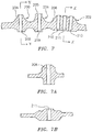
- FIG. 7 is a cross-sectional view of boss 200-202 according to another disclosed non-limiting embodiment.
- top surfaces 204-206 of the boss surrounding through holes 208-212 are not planar, or even necessarily symmetrical, immediately adjacent the through holes 208-212.
- FIG. 7A is a cross-sectional illustration taken along the line Y-Y in FIG. 7.
- FIG. 7B is a cross-sectional illustration taken along the line Z-Z in FIG. 7 .
Landscapes
- Engineering & Computer Science (AREA)
- Mechanical Engineering (AREA)
- General Engineering & Computer Science (AREA)
- Chemical & Material Sciences (AREA)
- Combustion & Propulsion (AREA)
- Physics & Mathematics (AREA)
- Thermal Sciences (AREA)
- Structures Of Non-Positive Displacement Pumps (AREA)
Applications Claiming Priority (1)
| Application Number | Priority Date | Filing Date | Title |
|---|---|---|---|
| US15/720,523 US20190101022A1 (en) | 2017-09-29 | 2017-09-29 | Contoured case bosses for a gas turbine engine |
Publications (1)
| Publication Number | Publication Date |
|---|---|
| EP3461999A1 true EP3461999A1 (de) | 2019-04-03 |
Family
ID=63685762
Family Applications (1)
| Application Number | Title | Priority Date | Filing Date |
|---|---|---|---|
| EP18196957.7A Withdrawn EP3461999A1 (de) | 2017-09-29 | 2018-09-26 | Konturierte gehäusebuckel für einen gasturbinenmotor |
Country Status (2)
| Country | Link |
|---|---|
| US (1) | US20190101022A1 (de) |
| EP (1) | EP3461999A1 (de) |
Families Citing this family (1)
| Publication number | Priority date | Publication date | Assignee | Title |
|---|---|---|---|---|
| US11261757B2 (en) | 2019-12-05 | 2022-03-01 | Pratt & Whitney Canada Corp. | Boss for gas turbine engine |
Citations (4)
| Publication number | Priority date | Publication date | Assignee | Title |
|---|---|---|---|---|
| WO2014105781A1 (en) * | 2012-12-29 | 2014-07-03 | United Technologies Corporation | Frame strut cooling holes |
| WO2015038931A1 (en) * | 2013-09-13 | 2015-03-19 | United Technologies Corporation | Shielding pockets for case holes |
| US20160356222A1 (en) * | 2014-02-19 | 2016-12-08 | United Technologies Corporation | Reduced stress boss geometry for a gas turbine engine |
| WO2017134844A1 (ja) * | 2016-02-04 | 2017-08-10 | 三菱重工航空エンジン株式会社 | 航空部品及び航空用ガスタービンエンジン |
-
2017
- 2017-09-29 US US15/720,523 patent/US20190101022A1/en not_active Abandoned
-
2018
- 2018-09-26 EP EP18196957.7A patent/EP3461999A1/de not_active Withdrawn
Patent Citations (4)
| Publication number | Priority date | Publication date | Assignee | Title |
|---|---|---|---|---|
| WO2014105781A1 (en) * | 2012-12-29 | 2014-07-03 | United Technologies Corporation | Frame strut cooling holes |
| WO2015038931A1 (en) * | 2013-09-13 | 2015-03-19 | United Technologies Corporation | Shielding pockets for case holes |
| US20160356222A1 (en) * | 2014-02-19 | 2016-12-08 | United Technologies Corporation | Reduced stress boss geometry for a gas turbine engine |
| WO2017134844A1 (ja) * | 2016-02-04 | 2017-08-10 | 三菱重工航空エンジン株式会社 | 航空部品及び航空用ガスタービンエンジン |
Also Published As
| Publication number | Publication date |
|---|---|
| US20190101022A1 (en) | 2019-04-04 |
Similar Documents
| Publication | Publication Date | Title |
|---|---|---|
| US11208955B2 (en) | Reduced stress boss geometry for a gas turbine engine | |
| US10329956B2 (en) | Multi-function boss for a turbine exhaust case | |
| EP2565395B1 (de) | Zugstange für einen Gasturbinenmotor | |
| EP3090209B1 (de) | Gekühlte tülle für eine brennkammerwandanordnung einer gasturbine | |
| EP2817496B1 (de) | Turbinenrahmenverkleidung für einen gasturbinenmotor | |
| EP3066318B1 (de) | Innendiffusorgehäuse für einen gasturbinenmotor | |
| EP2895796B1 (de) | Leichtgewichtiger wirbler für eine gasturbinenbrennkammer und verfahren zur herstellung | |
| US9765649B2 (en) | Borescope inspection port fitting | |
| EP2995863B1 (de) | Einwandige brennkammer für ein gasturbinenmotor und verfahren zur herstellung | |
| EP2927595B1 (de) | Schutzmanschettenanordnung und verfahren zum entwurf | |
| EP3039344B1 (de) | Wirblerhalterungsverbindung für eine gasturbinenbrennkammer | |
| US20130323045A1 (en) | Seal land for static structure of a gas turbine engine | |
| EP3719259A1 (de) | Vordiffusor für einen gasturbinenmotor | |
| US11226102B2 (en) | Fuel nozzle for a gas turbine engine | |
| US20230089675A1 (en) | Pre-diffuser for a gas turbine engine | |
| EP3719261A1 (de) | Vordiffusor für einen gasturbinenmotor | |
| US10690006B2 (en) | Shielding pockets for case holes | |
| EP3461999A1 (de) | Konturierte gehäusebuckel für einen gasturbinenmotor | |
| EP3534071B1 (de) | Gasturbinenmotor umfassend eine befestigungsanordnung mit einem lecksicheren gewindeeinsatz | |
| EP3557005B1 (de) | Dichtungsanordnung mit schild für gasturbinentriebwerke | |
| WO2015084450A2 (en) | Shielding pockets for case holes | |
| US20230323792A1 (en) | Vane system with continuous support ring | |
| EP3851744A1 (de) | Konvektionskühlung im bereich niedriger effusionsdichte einer brennkammerplatte | |
| US20180149169A1 (en) | Support structure for radial inlet of gas turbine engine |
Legal Events
| Date | Code | Title | Description |
|---|---|---|---|
| PUAI | Public reference made under article 153(3) epc to a published international application that has entered the european phase |
Free format text: ORIGINAL CODE: 0009012 |
|
| STAA | Information on the status of an ep patent application or granted ep patent |
Free format text: STATUS: THE APPLICATION HAS BEEN PUBLISHED |
|
| AK | Designated contracting states |
Kind code of ref document: A1 Designated state(s): AL AT BE BG CH CY CZ DE DK EE ES FI FR GB GR HR HU IE IS IT LI LT LU LV MC MK MT NL NO PL PT RO RS SE SI SK SM TR |
|
| AX | Request for extension of the european patent |
Extension state: BA ME |
|
| RIN1 | Information on inventor provided before grant (corrected) |
Inventor name: SCOTT, JONATHAN A Inventor name: BETANCOURT, FABIAN D Inventor name: SEDOR, JOSEPH J Inventor name: STRAUSBAUGH, JEFFREY C Inventor name: QUACH, SAN Inventor name: JONES, MAJOR D |
|
| RIN1 | Information on inventor provided before grant (corrected) |
Inventor name: STRAUSBAUGH, JEFFREY C Inventor name: SCOTT, JONATHAN A Inventor name: JONES, MAJOR D Inventor name: BETANCOURT, FABIAN D Inventor name: QUACH, SAN Inventor name: SEDOR, JOSEPH J |
|
| STAA | Information on the status of an ep patent application or granted ep patent |
Free format text: STATUS: REQUEST FOR EXAMINATION WAS MADE |
|
| 17P | Request for examination filed |
Effective date: 20191003 |
|
| RBV | Designated contracting states (corrected) |
Designated state(s): AL AT BE BG CH CY CZ DE DK EE ES FI FR GB GR HR HU IE IS IT LI LT LU LV MC MK MT NL NO PL PT RO RS SE SI SK SM TR |
|
| STAA | Information on the status of an ep patent application or granted ep patent |
Free format text: STATUS: EXAMINATION IS IN PROGRESS |
|
| 17Q | First examination report despatched |
Effective date: 20200421 |
|
| STAA | Information on the status of an ep patent application or granted ep patent |
Free format text: STATUS: EXAMINATION IS IN PROGRESS |
|
| RAP1 | Party data changed (applicant data changed or rights of an application transferred) |
Owner name: RAYTHEON TECHNOLOGIES CORPORATION |
|
| STAA | Information on the status of an ep patent application or granted ep patent |
Free format text: STATUS: THE APPLICATION IS DEEMED TO BE WITHDRAWN |
|
| 18D | Application deemed to be withdrawn |
Effective date: 20210420 |