EP3461667A1 - Passenger airflow control devices - Google Patents
Passenger airflow control devices Download PDFInfo
- Publication number
- EP3461667A1 EP3461667A1 EP18197991.5A EP18197991A EP3461667A1 EP 3461667 A1 EP3461667 A1 EP 3461667A1 EP 18197991 A EP18197991 A EP 18197991A EP 3461667 A1 EP3461667 A1 EP 3461667A1
- Authority
- EP
- European Patent Office
- Prior art keywords
- airflow
- central
- passenger
- shell
- receiver
- Prior art date
- Legal status (The legal status is an assumption and is not a legal conclusion. Google has not performed a legal analysis and makes no representation as to the accuracy of the status listed.)
- Granted
Links
- 238000007599 discharging Methods 0.000 claims abstract description 3
- 239000012530 fluid Substances 0.000 claims description 5
- 239000000463 material Substances 0.000 claims description 3
- 229920003023 plastic Polymers 0.000 claims description 3
- 239000004033 plastic Substances 0.000 claims description 3
- 230000000694 effects Effects 0.000 description 3
- 230000008901 benefit Effects 0.000 description 2
- 238000012986 modification Methods 0.000 description 2
- 230000004048 modification Effects 0.000 description 2
- 230000002411 adverse Effects 0.000 description 1
- 230000007613 environmental effect Effects 0.000 description 1
- 238000005286 illumination Methods 0.000 description 1
- 230000004941 influx Effects 0.000 description 1
- 230000035807 sensation Effects 0.000 description 1
- 230000000007 visual effect Effects 0.000 description 1
Images


Classifications
-
- B—PERFORMING OPERATIONS; TRANSPORTING
- B64—AIRCRAFT; AVIATION; COSMONAUTICS
- B64D—EQUIPMENT FOR FITTING IN OR TO AIRCRAFT; FLIGHT SUITS; PARACHUTES; ARRANGEMENTS OR MOUNTING OF POWER PLANTS OR PROPULSION TRANSMISSIONS IN AIRCRAFT
- B64D13/00—Arrangements or adaptations of air-treatment apparatus for aircraft crew or passengers, or freight space, or structural parts of the aircraft
- B64D13/06—Arrangements or adaptations of air-treatment apparatus for aircraft crew or passengers, or freight space, or structural parts of the aircraft the air being conditioned
-
- B—PERFORMING OPERATIONS; TRANSPORTING
- B60—VEHICLES IN GENERAL
- B60H—ARRANGEMENTS OF HEATING, COOLING, VENTILATING OR OTHER AIR-TREATING DEVICES SPECIALLY ADAPTED FOR PASSENGER OR GOODS SPACES OF VEHICLES
- B60H1/00—Heating, cooling or ventilating [HVAC] devices
- B60H1/34—Nozzles; Air-diffusers
- B60H1/3414—Nozzles; Air-diffusers with means for adjusting the air stream direction
-
- B—PERFORMING OPERATIONS; TRANSPORTING
- B64—AIRCRAFT; AVIATION; COSMONAUTICS
- B64D—EQUIPMENT FOR FITTING IN OR TO AIRCRAFT; FLIGHT SUITS; PARACHUTES; ARRANGEMENTS OR MOUNTING OF POWER PLANTS OR PROPULSION TRANSMISSIONS IN AIRCRAFT
- B64D13/00—Arrangements or adaptations of air-treatment apparatus for aircraft crew or passengers, or freight space, or structural parts of the aircraft
- B64D2013/003—Cabin ventilation nozzles
-
- B—PERFORMING OPERATIONS; TRANSPORTING
- B64—AIRCRAFT; AVIATION; COSMONAUTICS
- B64D—EQUIPMENT FOR FITTING IN OR TO AIRCRAFT; FLIGHT SUITS; PARACHUTES; ARRANGEMENTS OR MOUNTING OF POWER PLANTS OR PROPULSION TRANSMISSIONS IN AIRCRAFT
- B64D13/00—Arrangements or adaptations of air-treatment apparatus for aircraft crew or passengers, or freight space, or structural parts of the aircraft
- B64D13/06—Arrangements or adaptations of air-treatment apparatus for aircraft crew or passengers, or freight space, or structural parts of the aircraft the air being conditioned
- B64D2013/0603—Environmental Control Systems
- B64D2013/0688—Environmental Control Systems with means for recirculating cabin air
-
- B—PERFORMING OPERATIONS; TRANSPORTING
- B64—AIRCRAFT; AVIATION; COSMONAUTICS
- B64D—EQUIPMENT FOR FITTING IN OR TO AIRCRAFT; FLIGHT SUITS; PARACHUTES; ARRANGEMENTS OR MOUNTING OF POWER PLANTS OR PROPULSION TRANSMISSIONS IN AIRCRAFT
- B64D2203/00—Aircraft or airfield lights using LEDs
Definitions
- the embodiments disclosed herein relate generally to devices that may usefully be employed in the interior of passenger transport vehicles which allow a passenger to adjust incoming airflow as may be needed to enhance comfort.
- the interior of transport vehicles are conventionally provided with an airflow outlet that a passenger can manually manipulated so as to achieve a desired influx of airflow for comfort.
- Conventional aiflow outlets allow the passenger to selectively adjust the direction and/or volume of airflow by means of a variety of designs including, for example, adjustable horizontal/vertical vanes, adjustable louvers and/or valve outlets.
- PSU overhead passenger service units
- passenger airflow control devices that may be employed in passenger transport vehicles (e.g., passenger transport aircraft, trains, buses, automobiles and the like) that allow individual passengers to selectively control direction and volume of incoming airflow to thereby enhance passenger comfort.
- passenger airflow control devices are provided with an open-ended domed shell, a receiver immovably fixed to an upper end of the shell and a central air distributor assembly operatively connected to the receiver for receiving an incoming airflow and discharging the airflow to a passenger.
- the central air distributor assembly may include a central distributor bowl which defines a laterally oriented airflow discharge opening, a central disk which is positionally fixed to and closes a lower end of the central distributor bowl, and an air distributor hub having a lower end immovably connected to an upper end of the central distributor bowl and an upper stem which is received within and rotatably connected to the receiver.
- the air distributor hub may define an interior space in fluid communication with the air discharge opening of the central distributor bowl.
- An air inlet cutout which is capable of fluid communication with the incoming airflow may be defined by the upper stem.
- Rotational movement of the central air distributor assembly will therefore responsively move the air inlet cutout of the air distributor hub relative to the incoming airflow between open and closed conditions and also concurrently move the discharge opening of the central distributor bowl to allow directional control of the airflow discharged therefrom.
- the central disk of the central air distributor assembly may be substantially coplanar with or slightly upwardly recessed relative to a lower circumferential edge of the shell.
- An annular space may also be defined between a perimetrical edge of the central disk and the lower circumferential edge of the shell so as to allow a passenger to apply finger pressure to the disk in order to effect rotation of the central air distributor assembly.
- the shell may be formed of a transparent or translucent plastics material.
- the shell may be illuminated, e.g., by providing a light emitting diode (LED) internally of the PSU in which the airflow control device is provided.
- LED light emitting diode
- FIGS. 1-4 depict an exemplary interior aircraft cabin AC provided with passenger seats PS that are associated with overhead passenger service unit (PSU) provided with airflow control devices 10 in accordance with an embodiment of the present invention.
- PSU overhead passenger service unit
- FIGS. 1-4 depict an exemplary interior aircraft cabin AC provided with passenger seats PS that are associated with overhead passenger service unit (PSU) provided with airflow control devices 10 in accordance with an embodiment of the present invention.
- PSU overhead passenger service unit
- the airflow control devices 10 are flush-mounted relative to the PSU. That is, the airflow control devices 10 do not protrude beyond the plane of the PSU but may still be grasped and manipulated by a passenger to control the direction and/or volume of airflow discharged therefrom (see FIG. 3 ). Specifically, as will be explained in greater detail below, even though the airflow control devices 10 are flush-mounted relative to the PSU, the passenger may rotate the devices 10 so as to effect a change in direction and/or volume of airflow discharged therefrom as may be needed to enhance passenger comfort.
- the exemplary airflow control device 10 generally is comprised of a central air distributor assembly 12 which is positioned within a surrounding open-ended domed shell 14.
- the shell 14 includes an exteriorly threaded base portion 14a which is which threadably accepts a mounting ring 16 so as to mount the shell 10, and hence the airflow control device 10, to the PSU supporting structure (see FIG. 6 ).
- the diameter of the lower circumferential edge of shell 14 is sufficiently large so as to surround the central air distributor assembly 12 and to define an annular space 15 therebetween to allow a passenger to apply finger pressure to the central distributor assembly 12 in order to effect rotation thereof and thereby control the direction of discharged airflow (see FIG. 3 ).
- the shell 14 is also preferably formed of a transparent or translucent plastics material that may be illuminated by a light emitting diode (LED) (not shown) positioned within the PSU. In such a manner, therefore, the shell 14 serves as a visible light diffuser to thereby provide indirect illumination for the central air distributor assembly 12, and especially the disk 22 thereof.
- LED light emitting diode
- the central air distributor assembly 12 is generally comprised of a central distributor bowl 20 having a laterally oriented air discharge opening 20a.
- the lower end of the distributor bowl 20 is closed by an integrally connected central disk 22.
- the circumferential edge of the central disk 22 may be knurled and/or may be slightly larger diameter as compared to the diameter of the lower edge of the air distributor bowl 20 to which the disk is attached to thereby provide an enhanced tactile sensation when the passenger manually manipulates the assembly 12 by applying finger pressure to the circumferential edge of the disk 22.
- the central disk 22 is at least substantially coplanar with, or even slightly upwardly recessed relative to, the lower annular circumferential edge of the shell 14 so as to present a pleasing aesthetic appearance to the device 10 in the PSU.
- the central distributor bowl 20 is also integrally connected to a lower end of an air distributor hub 24 which includes an upwardly extending stem 24a defining an interior space 24b which is in fluid communication with the opening 20a of the distributor bowl 20.
- the upper end of the stem 24a is rotatably connected to a receiver 30 by means of a conventional fastener 25.
- the receiver 30 is in turn fluid-connected to an inlet air supply conduit 32 associated with the environmental control system (not show) for the aircraft cabin AC.
- the lower end of the receiver 30 includes an annular flange 30a which is positioned in the annular recess 14c defined by the upper annular boss 14b of the shell 14.
- the hub 24 includes a downwardly inclined and laterally oriented air deflection surface 24c which serves to redirect the air entering the interior space 24b from the air inlet conduit 32 toward the opening 20a and thereby provide an airflow direction which is downwardly and laterally oriented below the lower edge of the shell 14. In such a manner airflow impingement against the interior surface of the shell 14 will thus be minimized while the downward and lateral directional airflow exiting the opening 20a will be maximized.
- the stem 24a is therefore capable of being rotated about its elongate axis to allow reciprocal rotational movements of the central air distributor assembly 12 relative to the receiver 30 and relative to the shell 14 to which the receiver 30 is immovably attached (i.e., in the directions of arrow A1 in FIG. 3 ).
- the connection between the stem 24a and receiver 30 provided by fastener 25 may also be such that slight tiling of the central distributor assembly 12 relative to horizontal may occur to promote additional direction control over the airflow discharged from the air discharge opening 20a of the central distributor bowl 20 (e.g., by providing a conventional friction-fit ball and socket arrangement as part of the fastener 25).
- the upper end of the stem 24a defines an air inlet cutout 34 which is capable of being moved relative to the air inlet conduit 32 between open and closed conditions (i.e., a condition where the substantially entire area of the inlet cutout 34 is presented to the incoming airflow provided by the air inlet cutout 32 and a condition where stem 24a substantially blocks the incoming airflow provided by the air inlet cutout 34).
- the range of substantially fully open condition whereby substantially the entire area of the cutout 34 is exposed to the incoming airflow through the conduit 30 occurs throughout a rotational arc of the central air distributor assembly of about 90° with the remaining rotational orientation beyond such arc being between a modulated open condition (i.e., where at least some area of the cutout 34 is exposed to the incoming airflow through the conduit 30) to a fully closed condition.
- the orientation of the opening 20a is thereby provided to allow directional airflow control throughout such rotational movement of the air distributor assembly 12 as well as airflow volume control.
- the operational rotational limits of rotation of the assembly 12 is provided by a stop boss 30b extending downwardly from the flange 30a of the receiver 30 and a diametrically opposed pair of detents 20b provided at the upper annular collar 20c of the air distributor bowl (see FIG. 13 ).
- a light emitting diode (LED) (not shown) may be placed within the interior space 24b of the air distributor hub 24 so as to illuminate the opening 20a and thereby provide a visual indication of the orientation of the opening 20a (and hence the directional discharge of airflow therefrom) relative to the passenger.
Abstract
Description
- The embodiments disclosed herein relate generally to devices that may usefully be employed in the interior of passenger transport vehicles which allow a passenger to adjust incoming airflow as may be needed to enhance comfort.
- The interior of transport vehicles (e.g., passenger transport aircraft, trains, buses, automobiles and the like) are conventionally provided with an airflow outlet that a passenger can manually manipulated so as to achieve a desired influx of airflow for comfort. Conventional aiflow outlets allow the passenger to selectively adjust the direction and/or volume of airflow by means of a variety of designs including, for example, adjustable horizontal/vertical vanes, adjustable louvers and/or valve outlets. In transport aircraft, such conventional airflow outlets employed in an overhead passenger service units (PSU) tend to protrude downwardly which adversely affects the aesthetics of the interior cabin.
- What has been needed in the art, therefore are passenger airflow devices which may be aesthetically pleasing visually while still providing adjustable airflow capabilities to allow for passenger control. It is towards providing such devices that the embodiments disclosed herein are directed.
- In general, the embodiments disclosed herein relate to airflow control devices that may be employed in passenger transport vehicles (e.g., passenger transport aircraft, trains, buses, automobiles and the like) that allow individual passengers to selectively control direction and volume of incoming airflow to thereby enhance passenger comfort. According to certain embodiment, passenger airflow control devices are provided with an open-ended domed shell, a receiver immovably fixed to an upper end of the shell and a central air distributor assembly operatively connected to the receiver for receiving an incoming airflow and discharging the airflow to a passenger.
- The central air distributor assembly according to some embodiments disclosed herein may include a central distributor bowl which defines a laterally oriented airflow discharge opening, a central disk which is positionally fixed to and closes a lower end of the central distributor bowl, and an air distributor hub having a lower end immovably connected to an upper end of the central distributor bowl and an upper stem which is received within and rotatably connected to the receiver. The air distributor hub may define an interior space in fluid communication with the air discharge opening of the central distributor bowl. An air inlet cutout which is capable of fluid communication with the incoming airflow may be defined by the upper stem. Rotational movement of the central air distributor assembly will therefore responsively move the air inlet cutout of the air distributor hub relative to the incoming airflow between open and closed conditions and also concurrently move the discharge opening of the central distributor bowl to allow directional control of the airflow discharged therefrom.
- The central disk of the central air distributor assembly may be substantially coplanar with or slightly upwardly recessed relative to a lower circumferential edge of the shell. An annular space may also be defined between a perimetrical edge of the central disk and the lower circumferential edge of the shell so as to allow a passenger to apply finger pressure to the disk in order to effect rotation of the central air distributor assembly.
- According to some embodiments, the shell may be formed of a transparent or translucent plastics material. In order to enhance visibility of the central disk, the shell may be illuminated, e.g., by providing a light emitting diode (LED) internally of the PSU in which the airflow control device is provided.
- These and other aspects and advantages of the present invention will become more clear after careful consideration is given to the following detailed description of the preferred exemplary embodiments thereof.
- The disclosed embodiments of the present invention will be better and more completely understood by referring to the following detailed description of exemplary non-limiting illustrative embodiments in conjunction with the drawings of which:
-
FIG. 1 is a perspective view of an interior aircraft passenger cabin showing an embodiment of the airflow control devices employed in an exemplary overhead PSU; -
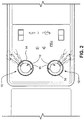
FIG. 2 is a plan view from below of the overhead PSU shown inFIG. 1 provided with the airflow control devices according to an embodiment of the invention; -
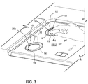
FIG. 3 is perspective view of the overhead PSU shown inFIG. 2 ; -
FIG. 4 is a detailed perspective view from below of the airflow control device employed in the PSU ofFIGS. 1-3 ; -
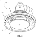
FIG. 5 is an enlarged perspective view from below the airflow control device in accordance with an embodiment of this invention showing the associated mounting structures and air supply conduits; -
FIG. 6 is a side elevational view of the airflow control device depicted nFIG. 5 ; -
FIG. 7 is a cross-sectional view of the airflow control device as taken along lines 7-7 inFIG. 6 ; -
FIG. 8 is an exploded perspective view of the airflow control device depicted inFIG. 5 ; -
FIGS. 9A and9B are exploded perspective views of the central air distributor assembly as shown in front and rear orientations thereof, respectively; -
FIG. 10 is a perspective view, partly in section, showing the internal air distributor assembly in relationship to the surrounding domed shell employed in the airflow control device; -
FIGS. 11A-11B and 12A-12B are perspective and partly sectioned top plan views showing different operational orientations of the central air distributor assembly relative to the incoming airflow, respectively; and -
FIG. 13 is an exploded perspective view showing the operative interconnection between the upper annular collar of the air distributor bowl and the flange of the receiver. - Accompanying
FIGS. 1-4 depict an exemplary interior aircraft cabin AC provided with passenger seats PS that are associated with overhead passenger service unit (PSU) provided withairflow control devices 10 in accordance with an embodiment of the present invention. It will of course be recognized that the depiction and description of theairflow control devices 10 being employed in an interior aircraft cabin AC is only one example of the type of passenger transport vehicles which can usefully benefit from the embodiments disclosed herein. Thus, the although the following description and accompanying drawings are presented in the context of theairflow control devices 10 being usefully employed in the context of a PSU associated with an interior aircraft cabin AC, it will be understood that such description and depiction is an exemplary non-limiting embodiment of the invention. - In the embodiments depicted, the
airflow control devices 10 are flush-mounted relative to the PSU. That is, theairflow control devices 10 do not protrude beyond the plane of the PSU but may still be grasped and manipulated by a passenger to control the direction and/or volume of airflow discharged therefrom (seeFIG. 3 ). Specifically, as will be explained in greater detail below, even though theairflow control devices 10 are flush-mounted relative to the PSU, the passenger may rotate thedevices 10 so as to effect a change in direction and/or volume of airflow discharged therefrom as may be needed to enhance passenger comfort. - As is depicted in greater detail in the enlarged views of
FIGS. 5-10 , the exemplaryairflow control device 10 generally is comprised of a centralair distributor assembly 12 which is positioned within a surrounding open-ended domed shell 14. Theshell 14 includes an exteriorly threadedbase portion 14a which is which threadably accepts amounting ring 16 so as to mount theshell 10, and hence theairflow control device 10, to the PSU supporting structure (seeFIG. 6 ). - The diameter of the lower circumferential edge of
shell 14 is sufficiently large so as to surround the centralair distributor assembly 12 and to define anannular space 15 therebetween to allow a passenger to apply finger pressure to thecentral distributor assembly 12 in order to effect rotation thereof and thereby control the direction of discharged airflow (seeFIG. 3 ). Theshell 14 is also preferably formed of a transparent or translucent plastics material that may be illuminated by a light emitting diode (LED) (not shown) positioned within the PSU. In such a manner, therefore, theshell 14 serves as a visible light diffuser to thereby provide indirect illumination for the centralair distributor assembly 12, and especially thedisk 22 thereof. - The central
air distributor assembly 12 is generally comprised of acentral distributor bowl 20 having a laterally oriented air discharge opening 20a. The lower end of thedistributor bowl 20 is closed by an integrally connectedcentral disk 22. The circumferential edge of thecentral disk 22 may be knurled and/or may be slightly larger diameter as compared to the diameter of the lower edge of theair distributor bowl 20 to which the disk is attached to thereby provide an enhanced tactile sensation when the passenger manually manipulates theassembly 12 by applying finger pressure to the circumferential edge of thedisk 22. As is shown, thecentral disk 22 is at least substantially coplanar with, or even slightly upwardly recessed relative to, the lower annular circumferential edge of theshell 14 so as to present a pleasing aesthetic appearance to thedevice 10 in the PSU. - The
central distributor bowl 20 is also integrally connected to a lower end of anair distributor hub 24 which includes an upwardly extendingstem 24a defining aninterior space 24b which is in fluid communication with the opening 20a of thedistributor bowl 20. The upper end of thestem 24a is rotatably connected to areceiver 30 by means of aconventional fastener 25. Thereceiver 30 is in turn fluid-connected to an inletair supply conduit 32 associated with the environmental control system (not show) for the aircraft cabin AC. The lower end of thereceiver 30 includes anannular flange 30a which is positioned in theannular recess 14c defined by the upperannular boss 14b of theshell 14. An outer edge of a split-ring retainer 33 is positioned in an interiorannular slot 14c-1 formed in theannular recess 14c of theupper boss 14b so as immovably fix theflange 30a of thereceiver 30 to theshell 14. Thehub 24 includes a downwardly inclined and laterally orientedair deflection surface 24c which serves to redirect the air entering theinterior space 24b from theair inlet conduit 32 toward the opening 20a and thereby provide an airflow direction which is downwardly and laterally oriented below the lower edge of theshell 14. In such a manner airflow impingement against the interior surface of theshell 14 will thus be minimized while the downward and lateral directional airflow exiting the opening 20a will be maximized. - The
stem 24a is therefore capable of being rotated about its elongate axis to allow reciprocal rotational movements of the centralair distributor assembly 12 relative to thereceiver 30 and relative to theshell 14 to which thereceiver 30 is immovably attached (i.e., in the directions of arrow A1 inFIG. 3 ). The connection between thestem 24a andreceiver 30 provided byfastener 25 may also be such that slight tiling of thecentral distributor assembly 12 relative to horizontal may occur to promote additional direction control over the airflow discharged from theair discharge opening 20a of the central distributor bowl 20 (e.g., by providing a conventional friction-fit ball and socket arrangement as part of the fastener 25). - As is perhaps more clearly shown in
FIGS. 11A-11B and 12A-12B , the upper end of thestem 24a defines anair inlet cutout 34 which is capable of being moved relative to theair inlet conduit 32 between open and closed conditions (i.e., a condition where the substantially entire area of theinlet cutout 34 is presented to the incoming airflow provided by theair inlet cutout 32 and a condition wherestem 24a substantially blocks the incoming airflow provided by the air inlet cutout 34). In the embodiment disclosed, the range of substantially fully open condition whereby substantially the entire area of thecutout 34 is exposed to the incoming airflow through theconduit 30 occurs throughout a rotational arc of the central air distributor assembly of about 90° with the remaining rotational orientation beyond such arc being between a modulated open condition (i.e., where at least some area of thecutout 34 is exposed to the incoming airflow through the conduit 30) to a fully closed condition. The orientation of the opening 20a is thereby provided to allow directional airflow control throughout such rotational movement of theair distributor assembly 12 as well as airflow volume control. The operational rotational limits of rotation of theassembly 12 is provided by astop boss 30b extending downwardly from theflange 30a of thereceiver 30 and a diametrically opposed pair ofdetents 20b provided at the upperannular collar 20c of the air distributor bowl (seeFIG. 13 ). A light emitting diode (LED) (not shown) may be placed within theinterior space 24b of theair distributor hub 24 so as to illuminate theopening 20a and thereby provide a visual indication of the orientation of theopening 20a (and hence the directional discharge of airflow therefrom) relative to the passenger. - Various modifications within the skill of those in the art may be envisioned. Therefore, while the invention has been described in connection with what is presently considered to be the most practical and preferred embodiment, it is to be understood that the invention is not to be limited to the disclosed embodiment, but on the contrary, is intended to cover various modifications and equivalent arrangements included within the spirit and scope thereof.
Claims (12)
- A passenger airflow control device comprising:an open-ended domed shell;a receiver immovably fixed to an upper end of the shell;a central air distributor assembly operatively connected to the receiver for receiving an incoming airflow and discharging the airflow to a passenger, wherein the central air distributor assembly includes:(i) a central distributor bowl which defines a laterally oriented airflow discharge opening;(ii) a central disk which is positionally fixed to and closes a lower end of the central distributor bowl; and(iii) an air distributor hub having a lower end immovably connected to an upper end of the central distributor bowl and an upper stem which is received within and rotatably connected to the receiver, wherein(iv) the air distributor hub defines an interior space in fluid communication with the air discharge opening of the central distributor bowl and includes an air inlet cutout which is capable of fluid communication with the incoming airflow, wherein rotational movement of the central air distributor assembly responsively moves the air inlet cutout of the air distributor hub relative to the incoming airflow between open and closed conditions and concurrently moves the discharge opening of the central distributor bowl to allow directional control of the airflow discharged therefrom.
- The device as in claim 1, wherein the central disk is substantially coplanar with a lower circumferential edge of the shell.
- The device as in claim 1 or 2, further comprising an annular space defined between a perimetrical edge of the central disk and the lower circumferential edge of the shell.
- The device as in one of the preceding claims, wherein the shell is formed of a transparent or translucent plastics material.
- The device as in one of the preceding claims, wherein the air distributor hub includes a downwardly inclined and laterally oriented air deflection surface to redirect the air entering the interior space toward the air discharge opening and thereby provide an airflow direction which is downwardly and laterally oriented below a lower circumferential edge of the shell.
- The device of one of the preceding claims, wherein
the shell includes an upper annular boss which defines an annular upper recess, and wherein
the receiver includes a lower flange which is received within the annular recess and positionally fixed therein to the upper annular boss of the shell. - The device of claim 6, wherein the upper annular boss includes an annular slot, and wherein the device further comprises a split-ring retainer received within the annular slot to positionally fix the lower flange of the receiver within the upper annular boss of the shell.
- The device of one of the preceding claims, which further comprises limit stops to limit an extent of rotational movement between the central air distributor assembly and the receiver.
- The device of claim 8, wherein the limit stops comprise a stop boss associated with the receiver and a pair of circumferentially separated detents associated with the air distributor bowl.
- The device of claim 9, wherein the detents are diametrically opposed relative to one another.
- An overhead passenger service unit which comprises at least one passenger airflow device as in one of the preceding claims.
- An interior aircraft cabin which includes passenger seats and an overhead passenger service unit (PSU) associated with the passenger seats, wherein the PSU comprises at least one passenger airflow device as in one of the preceding claims 1 to 10.
Applications Claiming Priority (1)
| Application Number | Priority Date | Filing Date | Title |
|---|---|---|---|
| US15/719,966 US10507925B2 (en) | 2017-09-29 | 2017-09-29 | Passenger airflow control devices |
Publications (2)
| Publication Number | Publication Date |
|---|---|
| EP3461667A1 true EP3461667A1 (en) | 2019-04-03 |
| EP3461667B1 EP3461667B1 (en) | 2020-04-29 |
Family
ID=63720594
Family Applications (1)
| Application Number | Title | Priority Date | Filing Date |
|---|---|---|---|
| EP18197991.5A Active EP3461667B1 (en) | 2017-09-29 | 2018-10-01 | Passenger airflow control device |
Country Status (4)
| Country | Link |
|---|---|
| US (1) | US10507925B2 (en) |
| EP (1) | EP3461667B1 (en) |
| CN (1) | CN109573053B (en) |
| BR (1) | BR102018070245A2 (en) |
Cited By (2)
| Publication number | Priority date | Publication date | Assignee | Title |
|---|---|---|---|---|
| DE102020125396A1 (en) | 2020-09-29 | 2022-03-31 | Beckhoff Automation Gmbh | Stator module for a linear transport system |
| US20230322405A1 (en) * | 2022-04-08 | 2023-10-12 | Textron Aviation Inc. | Plate Air and Light Bezel |
Families Citing this family (1)
| Publication number | Priority date | Publication date | Assignee | Title |
|---|---|---|---|---|
| US10906646B2 (en) * | 2018-05-11 | 2021-02-02 | B/E Aerospace, Inc. | Integrated passenger service unit (PSU) |
Citations (3)
| Publication number | Priority date | Publication date | Assignee | Title |
|---|---|---|---|---|
| US4102357A (en) * | 1975-10-24 | 1978-07-25 | Hawker Siddeley Aviation Limited | Variable flow outlet valves |
| DE102009008219A1 (en) * | 2009-02-10 | 2010-08-12 | GM Global Technology Operations, Inc., Detroit | Exhaust nozzle for air conditioning system of e.g. aircraft, has air guiding lamella including air guiding walls that make angle with respect to each other, and another air guiding lamella provided parallel to one of walls |
| US20170089471A1 (en) * | 2015-09-28 | 2017-03-30 | Gulfstream Aerospace Corporation | Ventilation systems and gasper valves with flexible components |
Family Cites Families (25)
| Publication number | Priority date | Publication date | Assignee | Title |
|---|---|---|---|---|
| US1748863A (en) * | 1929-05-31 | 1930-02-25 | Horace B Burke | Moisture-eliminating ventilator |
| GB1161111A (en) * | 1965-05-25 | 1969-08-13 | Humber Ltd | Ventilating valves for vehicles |
| US3319560A (en) * | 1965-10-11 | 1967-05-16 | Gen Motors Corp | Directional air vent nozzle with flexing vanes |
| US4742760A (en) * | 1987-07-06 | 1988-05-10 | The Boeing Company | Aircraft cabin ventilation system |
| US5399119A (en) * | 1993-08-10 | 1995-03-21 | Puritan-Bennett Corporation | Air valve device having flush closing nozzle |
| JP3735901B2 (en) * | 1995-02-03 | 2006-01-18 | 株式会社デンソー | Air passage switching device and vehicle air conditioner using the same |
| US6610116B1 (en) * | 2000-08-07 | 2003-08-26 | Neal H. Avery | Air filter system |
| EP1661806A1 (en) * | 2004-11-26 | 2006-05-31 | Goodrich Lighting Systems GmbH | Air outlet device for a vehicle |
| US20090163131A1 (en) * | 2006-05-18 | 2009-06-25 | Douglas Stuart Walkinshaw | Personal environment airflow controller |
| US7527402B2 (en) * | 2006-11-13 | 2009-05-05 | The Boeing Company | Integrated reading light and personal air outlet |
| DE102008022473B4 (en) * | 2008-05-07 | 2010-02-04 | Airbus Deutschland Gmbh | Adjustable visor for use in an air conditioning system, in particular an aircraft air conditioning system |
| DE102008051251B4 (en) * | 2008-10-10 | 2013-06-06 | Airbus Operations Gmbh | Supply device for a means of transport |
| DE102010008626A1 (en) * | 2010-02-19 | 2011-08-25 | Airbus Operations GmbH, 21129 | Supply air supply for passengers in aircraft |
| DE102010032233B3 (en) * | 2010-07-26 | 2011-07-21 | TRW Automotive Electronics & Components GmbH, 78315 | Air outlet for use in vehicle, has housing and air guiding device pivoted in housing, where bearing is provided, with which air guiding device is pivotably mounted on housing around swiveling axis |
| US10000289B2 (en) * | 2012-02-02 | 2018-06-19 | Senior Ip Gmbh | Temperature control gasper apparatus |
| US9045235B2 (en) * | 2013-07-31 | 2015-06-02 | Zodiac Aerotechnics | Service device, passenger service unit, fuselage of an aircraft, method for installing the service device |
| US9487296B2 (en) * | 2013-09-30 | 2016-11-08 | Peco Manufacturing Co., Inc. | Passenger service unit and related systems |
| US9267658B2 (en) * | 2013-11-01 | 2016-02-23 | GM Global Technology Operations LLC | Integral air vent and lamp assembly |
| JP6491874B2 (en) * | 2013-12-20 | 2019-03-27 | 日本プラスト株式会社 | Wind direction adjustment device |
| KR101551089B1 (en) * | 2014-05-12 | 2015-09-07 | 현대자동차주식회사 | Reading lamp for vehicle having air vent |
| US10081429B2 (en) * | 2014-07-21 | 2018-09-25 | The Boeing Company | Air diffuser systems, methods, and apparatuses |
| US9707826B2 (en) * | 2014-07-31 | 2017-07-18 | GM Global Technology Operations LLC | Airflow outlet |
| WO2016027183A1 (en) * | 2014-08-21 | 2016-02-25 | Bombardier Inc. | Retractable air gasper apparatus |
| DE202016002951U1 (en) * | 2016-05-10 | 2017-08-11 | GM Global Technology Operations LLC (n. d. Ges. d. Staates Delaware) | Air vent for arrangement in the interior of a motor vehicle |
| US10919366B2 (en) * | 2017-08-15 | 2021-02-16 | Ford Global Technologies, Llc | Multi-adjustable air register |
-
2017
- 2017-09-29 US US15/719,966 patent/US10507925B2/en active Active
-
2018
- 2018-09-30 CN CN201811154361.6A patent/CN109573053B/en active Active
- 2018-10-01 BR BR102018070245-9A patent/BR102018070245A2/en active Search and Examination
- 2018-10-01 EP EP18197991.5A patent/EP3461667B1/en active Active
Patent Citations (3)
| Publication number | Priority date | Publication date | Assignee | Title |
|---|---|---|---|---|
| US4102357A (en) * | 1975-10-24 | 1978-07-25 | Hawker Siddeley Aviation Limited | Variable flow outlet valves |
| DE102009008219A1 (en) * | 2009-02-10 | 2010-08-12 | GM Global Technology Operations, Inc., Detroit | Exhaust nozzle for air conditioning system of e.g. aircraft, has air guiding lamella including air guiding walls that make angle with respect to each other, and another air guiding lamella provided parallel to one of walls |
| US20170089471A1 (en) * | 2015-09-28 | 2017-03-30 | Gulfstream Aerospace Corporation | Ventilation systems and gasper valves with flexible components |
Cited By (4)
| Publication number | Priority date | Publication date | Assignee | Title |
|---|---|---|---|---|
| DE102020125396A1 (en) | 2020-09-29 | 2022-03-31 | Beckhoff Automation Gmbh | Stator module for a linear transport system |
| WO2022069438A1 (en) | 2020-09-29 | 2022-04-07 | Beckhoff Automation Gmbh | Stator module for a linear transport system |
| US20230322405A1 (en) * | 2022-04-08 | 2023-10-12 | Textron Aviation Inc. | Plate Air and Light Bezel |
| US11851207B2 (en) * | 2022-04-08 | 2023-12-26 | Textron Aviation Inc. | Plate air and light bezel |
Also Published As
| Publication number | Publication date |
|---|---|
| CN109573053B (en) | 2023-09-19 |
| US20190100317A1 (en) | 2019-04-04 |
| BR102018070245A2 (en) | 2019-09-17 |
| US10507925B2 (en) | 2019-12-17 |
| EP3461667B1 (en) | 2020-04-29 |
| CN109573053A (en) | 2019-04-05 |
Similar Documents
| Publication | Publication Date | Title |
|---|---|---|
| EP3461667B1 (en) | Passenger airflow control device | |
| US20080112155A1 (en) | Integrated Reading Light and Personal Air Outlet | |
| US20140003073A1 (en) | Passenger service unit comprising a ventilaton nozzle and a reading light | |
| US9523490B2 (en) | Reflectors and reflector orientation feature to prevent non-qualified trim | |
| US6350043B1 (en) | Behind panel mount, directional lighting bracket | |
| US9447953B2 (en) | Adjustable luminaire | |
| US7303327B2 (en) | Directionally controllable night light | |
| ES2275035T3 (en) | AIR OUTLET FOR A VENTILATION SYSTEM. | |
| US10670242B2 (en) | Luminaire with moveable and detachable lamp head | |
| US7370995B2 (en) | Console and light assembly | |
| CN105313638A (en) | Airflow outlet | |
| US20170248296A1 (en) | Rotatable and tiltable luminaire | |
| US11118368B2 (en) | Laminar water feature | |
| US7815329B2 (en) | Waterfall unit | |
| US20120075849A1 (en) | Lamp assembly and housing therefor | |
| EP3604004B1 (en) | Combined luminaire and air conditioning nozzle | |
| US20060209554A1 (en) | Adjusting device for head light system | |
| US5788220A (en) | Linearly actuated gas flow control assembly | |
| US20210071825A1 (en) | Cross-country running lamp | |
| US20100015908A1 (en) | Vent cover plate | |
| US5909956A (en) | Motorcycle turn signal lens cover | |
| US10534373B2 (en) | Apparatus and method for locational aiming of an overhead directional service unit | |
| EP3388285B1 (en) | Installation member for a vehicle with an irradiating device | |
| CN207676845U (en) | A kind of light transmission column knob structure with arrow mark | |
| EP2813752A1 (en) | Vehicle lamp and lamp breather system |
Legal Events
| Date | Code | Title | Description |
|---|---|---|---|
| PUAI | Public reference made under article 153(3) epc to a published international application that has entered the european phase |
Free format text: ORIGINAL CODE: 0009012 |
|
| STAA | Information on the status of an ep patent application or granted ep patent |
Free format text: STATUS: THE APPLICATION HAS BEEN PUBLISHED |
|
| AK | Designated contracting states |
Kind code of ref document: A1 Designated state(s): AL AT BE BG CH CY CZ DE DK EE ES FI FR GB GR HR HU IE IS IT LI LT LU LV MC MK MT NL NO PL PT RO RS SE SI SK SM TR |
|
| AX | Request for extension of the european patent |
Extension state: BA ME |
|
| RIN1 | Information on inventor provided before grant (corrected) |
Inventor name: LOTH PUGLIESI, FERNANDA Inventor name: BEEVER, JAY Inventor name: KIMURA CASTANHA, BRUNO Inventor name: KARASAWA ZARONI, CASSIO |
|
| STAA | Information on the status of an ep patent application or granted ep patent |
Free format text: STATUS: REQUEST FOR EXAMINATION WAS MADE |
|
| 17P | Request for examination filed |
Effective date: 20191001 |
|
| RBV | Designated contracting states (corrected) |
Designated state(s): AL AT BE BG CH CY CZ DE DK EE ES FI FR GB GR HR HU IE IS IT LI LT LU LV MC MK MT NL NO PL PT RO RS SE SI SK SM TR |
|
| GRAP | Despatch of communication of intention to grant a patent |
Free format text: ORIGINAL CODE: EPIDOSNIGR1 |
|
| STAA | Information on the status of an ep patent application or granted ep patent |
Free format text: STATUS: GRANT OF PATENT IS INTENDED |
|
| INTG | Intention to grant announced |
Effective date: 20191121 |
|
| GRAS | Grant fee paid |
Free format text: ORIGINAL CODE: EPIDOSNIGR3 |
|
| GRAA | (expected) grant |
Free format text: ORIGINAL CODE: 0009210 |
|
| STAA | Information on the status of an ep patent application or granted ep patent |
Free format text: STATUS: THE PATENT HAS BEEN GRANTED |
|
| AK | Designated contracting states |
Kind code of ref document: B1 Designated state(s): AL AT BE BG CH CY CZ DE DK EE ES FI FR GB GR HR HU IE IS IT LI LT LU LV MC MK MT NL NO PL PT RO RS SE SI SK SM TR |
|
| REG | Reference to a national code |
Ref country code: GB Ref legal event code: FG4D |
|
| REG | Reference to a national code |
Ref country code: CH Ref legal event code: EP |
|
| REG | Reference to a national code |
Ref country code: AT Ref legal event code: REF Ref document number: 1262769 Country of ref document: AT Kind code of ref document: T Effective date: 20200515 |
|
| REG | Reference to a national code |
Ref country code: DE Ref legal event code: R096 Ref document number: 602018004165 Country of ref document: DE |
|
| REG | Reference to a national code |
Ref country code: IE Ref legal event code: FG4D |
|
| REG | Reference to a national code |
Ref country code: NL Ref legal event code: MP Effective date: 20200429 |
|
| REG | Reference to a national code |
Ref country code: LT Ref legal event code: MG4D |
|
| PG25 | Lapsed in a contracting state [announced via postgrant information from national office to epo] |
Ref country code: NO Free format text: LAPSE BECAUSE OF FAILURE TO SUBMIT A TRANSLATION OF THE DESCRIPTION OR TO PAY THE FEE WITHIN THE PRESCRIBED TIME-LIMIT Effective date: 20200729 Ref country code: IS Free format text: LAPSE BECAUSE OF FAILURE TO SUBMIT A TRANSLATION OF THE DESCRIPTION OR TO PAY THE FEE WITHIN THE PRESCRIBED TIME-LIMIT Effective date: 20200829 Ref country code: SE Free format text: LAPSE BECAUSE OF FAILURE TO SUBMIT A TRANSLATION OF THE DESCRIPTION OR TO PAY THE FEE WITHIN THE PRESCRIBED TIME-LIMIT Effective date: 20200429 Ref country code: FI Free format text: LAPSE BECAUSE OF FAILURE TO SUBMIT A TRANSLATION OF THE DESCRIPTION OR TO PAY THE FEE WITHIN THE PRESCRIBED TIME-LIMIT Effective date: 20200429 Ref country code: GR Free format text: LAPSE BECAUSE OF FAILURE TO SUBMIT A TRANSLATION OF THE DESCRIPTION OR TO PAY THE FEE WITHIN THE PRESCRIBED TIME-LIMIT Effective date: 20200730 Ref country code: PT Free format text: LAPSE BECAUSE OF FAILURE TO SUBMIT A TRANSLATION OF THE DESCRIPTION OR TO PAY THE FEE WITHIN THE PRESCRIBED TIME-LIMIT Effective date: 20200831 Ref country code: LT Free format text: LAPSE BECAUSE OF FAILURE TO SUBMIT A TRANSLATION OF THE DESCRIPTION OR TO PAY THE FEE WITHIN THE PRESCRIBED TIME-LIMIT Effective date: 20200429 |
|
| REG | Reference to a national code |
Ref country code: AT Ref legal event code: MK05 Ref document number: 1262769 Country of ref document: AT Kind code of ref document: T Effective date: 20200429 |
|
| PG25 | Lapsed in a contracting state [announced via postgrant information from national office to epo] |
Ref country code: HR Free format text: LAPSE BECAUSE OF FAILURE TO SUBMIT A TRANSLATION OF THE DESCRIPTION OR TO PAY THE FEE WITHIN THE PRESCRIBED TIME-LIMIT Effective date: 20200429 Ref country code: BG Free format text: LAPSE BECAUSE OF FAILURE TO SUBMIT A TRANSLATION OF THE DESCRIPTION OR TO PAY THE FEE WITHIN THE PRESCRIBED TIME-LIMIT Effective date: 20200729 Ref country code: LV Free format text: LAPSE BECAUSE OF FAILURE TO SUBMIT A TRANSLATION OF THE DESCRIPTION OR TO PAY THE FEE WITHIN THE PRESCRIBED TIME-LIMIT Effective date: 20200429 Ref country code: RS Free format text: LAPSE BECAUSE OF FAILURE TO SUBMIT A TRANSLATION OF THE DESCRIPTION OR TO PAY THE FEE WITHIN THE PRESCRIBED TIME-LIMIT Effective date: 20200429 |
|
| PG25 | Lapsed in a contracting state [announced via postgrant information from national office to epo] |
Ref country code: AL Free format text: LAPSE BECAUSE OF FAILURE TO SUBMIT A TRANSLATION OF THE DESCRIPTION OR TO PAY THE FEE WITHIN THE PRESCRIBED TIME-LIMIT Effective date: 20200429 Ref country code: NL Free format text: LAPSE BECAUSE OF FAILURE TO SUBMIT A TRANSLATION OF THE DESCRIPTION OR TO PAY THE FEE WITHIN THE PRESCRIBED TIME-LIMIT Effective date: 20200429 |
|
| PG25 | Lapsed in a contracting state [announced via postgrant information from national office to epo] |
Ref country code: DK Free format text: LAPSE BECAUSE OF FAILURE TO SUBMIT A TRANSLATION OF THE DESCRIPTION OR TO PAY THE FEE WITHIN THE PRESCRIBED TIME-LIMIT Effective date: 20200429 Ref country code: AT Free format text: LAPSE BECAUSE OF FAILURE TO SUBMIT A TRANSLATION OF THE DESCRIPTION OR TO PAY THE FEE WITHIN THE PRESCRIBED TIME-LIMIT Effective date: 20200429 Ref country code: IT Free format text: LAPSE BECAUSE OF FAILURE TO SUBMIT A TRANSLATION OF THE DESCRIPTION OR TO PAY THE FEE WITHIN THE PRESCRIBED TIME-LIMIT Effective date: 20200429 Ref country code: SM Free format text: LAPSE BECAUSE OF FAILURE TO SUBMIT A TRANSLATION OF THE DESCRIPTION OR TO PAY THE FEE WITHIN THE PRESCRIBED TIME-LIMIT Effective date: 20200429 Ref country code: EE Free format text: LAPSE BECAUSE OF FAILURE TO SUBMIT A TRANSLATION OF THE DESCRIPTION OR TO PAY THE FEE WITHIN THE PRESCRIBED TIME-LIMIT Effective date: 20200429 Ref country code: RO Free format text: LAPSE BECAUSE OF FAILURE TO SUBMIT A TRANSLATION OF THE DESCRIPTION OR TO PAY THE FEE WITHIN THE PRESCRIBED TIME-LIMIT Effective date: 20200429 Ref country code: CZ Free format text: LAPSE BECAUSE OF FAILURE TO SUBMIT A TRANSLATION OF THE DESCRIPTION OR TO PAY THE FEE WITHIN THE PRESCRIBED TIME-LIMIT Effective date: 20200429 Ref country code: ES Free format text: LAPSE BECAUSE OF FAILURE TO SUBMIT A TRANSLATION OF THE DESCRIPTION OR TO PAY THE FEE WITHIN THE PRESCRIBED TIME-LIMIT Effective date: 20200429 |
|
| REG | Reference to a national code |
Ref country code: DE Ref legal event code: R097 Ref document number: 602018004165 Country of ref document: DE |
|
| PG25 | Lapsed in a contracting state [announced via postgrant information from national office to epo] |
Ref country code: SK Free format text: LAPSE BECAUSE OF FAILURE TO SUBMIT A TRANSLATION OF THE DESCRIPTION OR TO PAY THE FEE WITHIN THE PRESCRIBED TIME-LIMIT Effective date: 20200429 Ref country code: PL Free format text: LAPSE BECAUSE OF FAILURE TO SUBMIT A TRANSLATION OF THE DESCRIPTION OR TO PAY THE FEE WITHIN THE PRESCRIBED TIME-LIMIT Effective date: 20200429 |
|
| PLBE | No opposition filed within time limit |
Free format text: ORIGINAL CODE: 0009261 |
|
| STAA | Information on the status of an ep patent application or granted ep patent |
Free format text: STATUS: NO OPPOSITION FILED WITHIN TIME LIMIT |
|
| 26N | No opposition filed |
Effective date: 20210201 |
|
| REG | Reference to a national code |
Ref country code: DE Ref legal event code: R119 Ref document number: 602018004165 Country of ref document: DE |
|
| PG25 | Lapsed in a contracting state [announced via postgrant information from national office to epo] |
Ref country code: SI Free format text: LAPSE BECAUSE OF FAILURE TO SUBMIT A TRANSLATION OF THE DESCRIPTION OR TO PAY THE FEE WITHIN THE PRESCRIBED TIME-LIMIT Effective date: 20200429 |
|
| PG25 | Lapsed in a contracting state [announced via postgrant information from national office to epo] |
Ref country code: LU Free format text: LAPSE BECAUSE OF NON-PAYMENT OF DUE FEES Effective date: 20201001 Ref country code: MC Free format text: LAPSE BECAUSE OF FAILURE TO SUBMIT A TRANSLATION OF THE DESCRIPTION OR TO PAY THE FEE WITHIN THE PRESCRIBED TIME-LIMIT Effective date: 20200429 |
|
| REG | Reference to a national code |
Ref country code: BE Ref legal event code: MM Effective date: 20201031 |
|
| PG25 | Lapsed in a contracting state [announced via postgrant information from national office to epo] |
Ref country code: DE Free format text: LAPSE BECAUSE OF NON-PAYMENT OF DUE FEES Effective date: 20210501 |
|
| PG25 | Lapsed in a contracting state [announced via postgrant information from national office to epo] |
Ref country code: BE Free format text: LAPSE BECAUSE OF NON-PAYMENT OF DUE FEES Effective date: 20201031 |
|
| PG25 | Lapsed in a contracting state [announced via postgrant information from national office to epo] |
Ref country code: IE Free format text: LAPSE BECAUSE OF NON-PAYMENT OF DUE FEES Effective date: 20201001 |
|
| REG | Reference to a national code |
Ref country code: CH Ref legal event code: PL |
|
| PG25 | Lapsed in a contracting state [announced via postgrant information from national office to epo] |
Ref country code: TR Free format text: LAPSE BECAUSE OF FAILURE TO SUBMIT A TRANSLATION OF THE DESCRIPTION OR TO PAY THE FEE WITHIN THE PRESCRIBED TIME-LIMIT Effective date: 20200429 Ref country code: MT Free format text: LAPSE BECAUSE OF FAILURE TO SUBMIT A TRANSLATION OF THE DESCRIPTION OR TO PAY THE FEE WITHIN THE PRESCRIBED TIME-LIMIT Effective date: 20200429 Ref country code: CY Free format text: LAPSE BECAUSE OF FAILURE TO SUBMIT A TRANSLATION OF THE DESCRIPTION OR TO PAY THE FEE WITHIN THE PRESCRIBED TIME-LIMIT Effective date: 20200429 |
|
| PG25 | Lapsed in a contracting state [announced via postgrant information from national office to epo] |
Ref country code: MK Free format text: LAPSE BECAUSE OF FAILURE TO SUBMIT A TRANSLATION OF THE DESCRIPTION OR TO PAY THE FEE WITHIN THE PRESCRIBED TIME-LIMIT Effective date: 20200429 |
|
| PG25 | Lapsed in a contracting state [announced via postgrant information from national office to epo] |
Ref country code: LI Free format text: LAPSE BECAUSE OF NON-PAYMENT OF DUE FEES Effective date: 20211031 Ref country code: CH Free format text: LAPSE BECAUSE OF NON-PAYMENT OF DUE FEES Effective date: 20211031 |
|
| GBPC | Gb: european patent ceased through non-payment of renewal fee |
Effective date: 20221001 |
|
| PG25 | Lapsed in a contracting state [announced via postgrant information from national office to epo] |
Ref country code: GB Free format text: LAPSE BECAUSE OF NON-PAYMENT OF DUE FEES Effective date: 20221001 |
|
| PGFP | Annual fee paid to national office [announced via postgrant information from national office to epo] |
Ref country code: FR Payment date: 20231009 Year of fee payment: 6 |