EP3461632B1 - Composite sound absorption panel assembly - Google Patents
Composite sound absorption panel assembly Download PDFInfo
- Publication number
- EP3461632B1 EP3461632B1 EP18196779.5A EP18196779A EP3461632B1 EP 3461632 B1 EP3461632 B1 EP 3461632B1 EP 18196779 A EP18196779 A EP 18196779A EP 3461632 B1 EP3461632 B1 EP 3461632B1
- Authority
- EP
- European Patent Office
- Prior art keywords
- honeycomb layer
- elastic membrane
- honeycomb
- partition walls
- resonance cavities
- Prior art date
- Legal status (The legal status is an assumption and is not a legal conclusion. Google has not performed a legal analysis and makes no representation as to the accuracy of the status listed.)
- Active
Links
- 239000002131 composite material Substances 0.000 title claims description 80
- 238000010521 absorption reaction Methods 0.000 title description 4
- 239000012528 membrane Substances 0.000 claims description 124
- 238000005192 partition Methods 0.000 claims description 104
- 210000003739 neck Anatomy 0.000 claims description 66
- 239000000463 material Substances 0.000 claims description 21
- 238000000034 method Methods 0.000 claims description 17
- 239000004593 Epoxy Substances 0.000 claims description 10
- 229920001971 elastomer Polymers 0.000 claims description 6
- 238000004519 manufacturing process Methods 0.000 description 19
- 239000000654 additive Substances 0.000 description 11
- 230000000996 additive effect Effects 0.000 description 11
- 230000000712 assembly Effects 0.000 description 6
- 238000000429 assembly Methods 0.000 description 6
- 238000004088 simulation Methods 0.000 description 6
- 230000005540 biological transmission Effects 0.000 description 5
- 238000006073 displacement reaction Methods 0.000 description 5
- 239000000853 adhesive Substances 0.000 description 4
- 230000001070 adhesive effect Effects 0.000 description 4
- 239000006260 foam Substances 0.000 description 4
- 238000010146 3D printing Methods 0.000 description 3
- 239000004952 Polyamide Substances 0.000 description 3
- 230000015572 biosynthetic process Effects 0.000 description 3
- 238000005219 brazing Methods 0.000 description 3
- 238000013461 design Methods 0.000 description 3
- 239000012530 fluid Substances 0.000 description 3
- 230000006870 function Effects 0.000 description 3
- 239000007769 metal material Substances 0.000 description 3
- 229920002647 polyamide Polymers 0.000 description 3
- 230000008569 process Effects 0.000 description 3
- 238000003466 welding Methods 0.000 description 3
- 244000043261 Hevea brasiliensis Species 0.000 description 2
- 238000002835 absorbance Methods 0.000 description 2
- 239000011358 absorbing material Substances 0.000 description 2
- 239000000919 ceramic Substances 0.000 description 2
- 230000008021 deposition Effects 0.000 description 2
- 230000009977 dual effect Effects 0.000 description 2
- 239000006261 foam material Substances 0.000 description 2
- 239000003779 heat-resistant material Substances 0.000 description 2
- 238000005259 measurement Methods 0.000 description 2
- 229920003052 natural elastomer Polymers 0.000 description 2
- 229920001194 natural rubber Polymers 0.000 description 2
- 230000004044 response Effects 0.000 description 2
- 239000003381 stabilizer Substances 0.000 description 2
- 238000012360 testing method Methods 0.000 description 2
- 238000012546 transfer Methods 0.000 description 2
- 206010011878 Deafness Diseases 0.000 description 1
- 239000006096 absorbing agent Substances 0.000 description 1
- 238000005452 bending Methods 0.000 description 1
- 239000011248 coating agent Substances 0.000 description 1
- 238000000576 coating method Methods 0.000 description 1
- 238000004891 communication Methods 0.000 description 1
- 230000008878 coupling Effects 0.000 description 1
- 238000010168 coupling process Methods 0.000 description 1
- 238000005859 coupling reaction Methods 0.000 description 1
- 230000001186 cumulative effect Effects 0.000 description 1
- 230000000694 effects Effects 0.000 description 1
- 239000002305 electric material Substances 0.000 description 1
- 230000009969 flowable effect Effects 0.000 description 1
- 239000000446 fuel Substances 0.000 description 1
- 230000004927 fusion Effects 0.000 description 1
- 230000010370 hearing loss Effects 0.000 description 1
- 231100000888 hearing loss Toxicity 0.000 description 1
- 208000016354 hearing loss disease Diseases 0.000 description 1
- 230000003137 locomotive effect Effects 0.000 description 1
- 238000012986 modification Methods 0.000 description 1
- 230000004048 modification Effects 0.000 description 1
- 238000000465 moulding Methods 0.000 description 1
- 239000004033 plastic Substances 0.000 description 1
- 229920003023 plastic Polymers 0.000 description 1
- 239000002574 poison Substances 0.000 description 1
- 231100000614 poison Toxicity 0.000 description 1
- 229920000642 polymer Polymers 0.000 description 1
- 238000012545 processing Methods 0.000 description 1
- 230000008439 repair process Effects 0.000 description 1
- 230000003362 replicative effect Effects 0.000 description 1
- 238000007789 sealing Methods 0.000 description 1
- 238000000110 selective laser sintering Methods 0.000 description 1
- 230000035939 shock Effects 0.000 description 1
- 230000007704 transition Effects 0.000 description 1
- 239000011800 void material Substances 0.000 description 1
Images

Classifications
-
- B—PERFORMING OPERATIONS; TRANSPORTING
- B64—AIRCRAFT; AVIATION; COSMONAUTICS
- B64C—AEROPLANES; HELICOPTERS
- B64C1/00—Fuselages; Constructional features common to fuselages, wings, stabilising surfaces or the like
- B64C1/40—Sound or heat insulation, e.g. using insulation blankets
-
- B—PERFORMING OPERATIONS; TRANSPORTING
- B32—LAYERED PRODUCTS
- B32B—LAYERED PRODUCTS, i.e. PRODUCTS BUILT-UP OF STRATA OF FLAT OR NON-FLAT, e.g. CELLULAR OR HONEYCOMB, FORM
- B32B15/00—Layered products comprising a layer of metal
-
- G—PHYSICS
- G10—MUSICAL INSTRUMENTS; ACOUSTICS
- G10K—SOUND-PRODUCING DEVICES; METHODS OR DEVICES FOR PROTECTING AGAINST, OR FOR DAMPING, NOISE OR OTHER ACOUSTIC WAVES IN GENERAL; ACOUSTICS NOT OTHERWISE PROVIDED FOR
- G10K11/00—Methods or devices for transmitting, conducting or directing sound in general; Methods or devices for protecting against, or for damping, noise or other acoustic waves in general
- G10K11/16—Methods or devices for protecting against, or for damping, noise or other acoustic waves in general
- G10K11/172—Methods or devices for protecting against, or for damping, noise or other acoustic waves in general using resonance effects
-
- B—PERFORMING OPERATIONS; TRANSPORTING
- B32—LAYERED PRODUCTS
- B32B—LAYERED PRODUCTS, i.e. PRODUCTS BUILT-UP OF STRATA OF FLAT OR NON-FLAT, e.g. CELLULAR OR HONEYCOMB, FORM
- B32B3/00—Layered products comprising a layer with external or internal discontinuities or unevennesses, or a layer of non-planar shape; Layered products comprising a layer having particular features of form
- B32B3/10—Layered products comprising a layer with external or internal discontinuities or unevennesses, or a layer of non-planar shape; Layered products comprising a layer having particular features of form characterised by a discontinuous layer, i.e. formed of separate pieces of material
- B32B3/12—Layered products comprising a layer with external or internal discontinuities or unevennesses, or a layer of non-planar shape; Layered products comprising a layer having particular features of form characterised by a discontinuous layer, i.e. formed of separate pieces of material characterised by a layer of regularly- arranged cells, e.g. a honeycomb structure
-
- B—PERFORMING OPERATIONS; TRANSPORTING
- B32—LAYERED PRODUCTS
- B32B—LAYERED PRODUCTS, i.e. PRODUCTS BUILT-UP OF STRATA OF FLAT OR NON-FLAT, e.g. CELLULAR OR HONEYCOMB, FORM
- B32B15/00—Layered products comprising a layer of metal
- B32B15/04—Layered products comprising a layer of metal comprising metal as the main or only constituent of a layer, which is next to another layer of the same or of a different material
- B32B15/043—Layered products comprising a layer of metal comprising metal as the main or only constituent of a layer, which is next to another layer of the same or of a different material of metal
-
- B—PERFORMING OPERATIONS; TRANSPORTING
- B32—LAYERED PRODUCTS
- B32B—LAYERED PRODUCTS, i.e. PRODUCTS BUILT-UP OF STRATA OF FLAT OR NON-FLAT, e.g. CELLULAR OR HONEYCOMB, FORM
- B32B15/00—Layered products comprising a layer of metal
- B32B15/04—Layered products comprising a layer of metal comprising metal as the main or only constituent of a layer, which is next to another layer of the same or of a different material
- B32B15/06—Layered products comprising a layer of metal comprising metal as the main or only constituent of a layer, which is next to another layer of the same or of a different material of natural rubber or synthetic rubber
-
- B—PERFORMING OPERATIONS; TRANSPORTING
- B32—LAYERED PRODUCTS
- B32B—LAYERED PRODUCTS, i.e. PRODUCTS BUILT-UP OF STRATA OF FLAT OR NON-FLAT, e.g. CELLULAR OR HONEYCOMB, FORM
- B32B15/00—Layered products comprising a layer of metal
- B32B15/04—Layered products comprising a layer of metal comprising metal as the main or only constituent of a layer, which is next to another layer of the same or of a different material
- B32B15/08—Layered products comprising a layer of metal comprising metal as the main or only constituent of a layer, which is next to another layer of the same or of a different material of synthetic resin
- B32B15/088—Layered products comprising a layer of metal comprising metal as the main or only constituent of a layer, which is next to another layer of the same or of a different material of synthetic resin comprising polyamides
-
- B—PERFORMING OPERATIONS; TRANSPORTING
- B32—LAYERED PRODUCTS
- B32B—LAYERED PRODUCTS, i.e. PRODUCTS BUILT-UP OF STRATA OF FLAT OR NON-FLAT, e.g. CELLULAR OR HONEYCOMB, FORM
- B32B25/00—Layered products comprising a layer of natural or synthetic rubber
-
- B—PERFORMING OPERATIONS; TRANSPORTING
- B32—LAYERED PRODUCTS
- B32B—LAYERED PRODUCTS, i.e. PRODUCTS BUILT-UP OF STRATA OF FLAT OR NON-FLAT, e.g. CELLULAR OR HONEYCOMB, FORM
- B32B25/00—Layered products comprising a layer of natural or synthetic rubber
- B32B25/04—Layered products comprising a layer of natural or synthetic rubber comprising rubber as the main or only constituent of a layer, which is next to another layer of the same or of a different material
- B32B25/042—Layered products comprising a layer of natural or synthetic rubber comprising rubber as the main or only constituent of a layer, which is next to another layer of the same or of a different material of natural rubber or synthetic rubber
-
- B—PERFORMING OPERATIONS; TRANSPORTING
- B32—LAYERED PRODUCTS
- B32B—LAYERED PRODUCTS, i.e. PRODUCTS BUILT-UP OF STRATA OF FLAT OR NON-FLAT, e.g. CELLULAR OR HONEYCOMB, FORM
- B32B25/00—Layered products comprising a layer of natural or synthetic rubber
- B32B25/04—Layered products comprising a layer of natural or synthetic rubber comprising rubber as the main or only constituent of a layer, which is next to another layer of the same or of a different material
- B32B25/08—Layered products comprising a layer of natural or synthetic rubber comprising rubber as the main or only constituent of a layer, which is next to another layer of the same or of a different material of synthetic resin
-
- B—PERFORMING OPERATIONS; TRANSPORTING
- B32—LAYERED PRODUCTS
- B32B—LAYERED PRODUCTS, i.e. PRODUCTS BUILT-UP OF STRATA OF FLAT OR NON-FLAT, e.g. CELLULAR OR HONEYCOMB, FORM
- B32B25/00—Layered products comprising a layer of natural or synthetic rubber
- B32B25/12—Layered products comprising a layer of natural or synthetic rubber comprising natural rubber
-
- B—PERFORMING OPERATIONS; TRANSPORTING
- B32—LAYERED PRODUCTS
- B32B—LAYERED PRODUCTS, i.e. PRODUCTS BUILT-UP OF STRATA OF FLAT OR NON-FLAT, e.g. CELLULAR OR HONEYCOMB, FORM
- B32B25/00—Layered products comprising a layer of natural or synthetic rubber
- B32B25/14—Layered products comprising a layer of natural or synthetic rubber comprising synthetic rubber copolymers
-
- B—PERFORMING OPERATIONS; TRANSPORTING
- B32—LAYERED PRODUCTS
- B32B—LAYERED PRODUCTS, i.e. PRODUCTS BUILT-UP OF STRATA OF FLAT OR NON-FLAT, e.g. CELLULAR OR HONEYCOMB, FORM
- B32B27/00—Layered products comprising a layer of synthetic resin
- B32B27/06—Layered products comprising a layer of synthetic resin as the main or only constituent of a layer, which is next to another layer of the same or of a different material
- B32B27/08—Layered products comprising a layer of synthetic resin as the main or only constituent of a layer, which is next to another layer of the same or of a different material of synthetic resin
-
- B—PERFORMING OPERATIONS; TRANSPORTING
- B32—LAYERED PRODUCTS
- B32B—LAYERED PRODUCTS, i.e. PRODUCTS BUILT-UP OF STRATA OF FLAT OR NON-FLAT, e.g. CELLULAR OR HONEYCOMB, FORM
- B32B27/00—Layered products comprising a layer of synthetic resin
- B32B27/34—Layered products comprising a layer of synthetic resin comprising polyamides
-
- B—PERFORMING OPERATIONS; TRANSPORTING
- B32—LAYERED PRODUCTS
- B32B—LAYERED PRODUCTS, i.e. PRODUCTS BUILT-UP OF STRATA OF FLAT OR NON-FLAT, e.g. CELLULAR OR HONEYCOMB, FORM
- B32B3/00—Layered products comprising a layer with external or internal discontinuities or unevennesses, or a layer of non-planar shape; Layered products comprising a layer having particular features of form
- B32B3/26—Layered products comprising a layer with external or internal discontinuities or unevennesses, or a layer of non-planar shape; Layered products comprising a layer having particular features of form characterised by a particular shape of the outline of the cross-section of a continuous layer; characterised by a layer with cavities or internal voids ; characterised by an apertured layer
- B32B3/266—Layered products comprising a layer with external or internal discontinuities or unevennesses, or a layer of non-planar shape; Layered products comprising a layer having particular features of form characterised by a particular shape of the outline of the cross-section of a continuous layer; characterised by a layer with cavities or internal voids ; characterised by an apertured layer characterised by an apertured layer, the apertures going through the whole thickness of the layer, e.g. expanded metal, perforated layer, slit layer regular cells B32B3/12
-
- B—PERFORMING OPERATIONS; TRANSPORTING
- B32—LAYERED PRODUCTS
- B32B—LAYERED PRODUCTS, i.e. PRODUCTS BUILT-UP OF STRATA OF FLAT OR NON-FLAT, e.g. CELLULAR OR HONEYCOMB, FORM
- B32B37/00—Methods or apparatus for laminating, e.g. by curing or by ultrasonic bonding
- B32B37/12—Methods or apparatus for laminating, e.g. by curing or by ultrasonic bonding characterised by using adhesives
-
- B—PERFORMING OPERATIONS; TRANSPORTING
- B32—LAYERED PRODUCTS
- B32B—LAYERED PRODUCTS, i.e. PRODUCTS BUILT-UP OF STRATA OF FLAT OR NON-FLAT, e.g. CELLULAR OR HONEYCOMB, FORM
- B32B7/00—Layered products characterised by the relation between layers; Layered products characterised by the relative orientation of features between layers, or by the relative values of a measurable parameter between layers, i.e. products comprising layers having different physical, chemical or physicochemical properties; Layered products characterised by the interconnection of layers
- B32B7/02—Physical, chemical or physicochemical properties
-
- B—PERFORMING OPERATIONS; TRANSPORTING
- B32—LAYERED PRODUCTS
- B32B—LAYERED PRODUCTS, i.e. PRODUCTS BUILT-UP OF STRATA OF FLAT OR NON-FLAT, e.g. CELLULAR OR HONEYCOMB, FORM
- B32B7/00—Layered products characterised by the relation between layers; Layered products characterised by the relative orientation of features between layers, or by the relative values of a measurable parameter between layers, i.e. products comprising layers having different physical, chemical or physicochemical properties; Layered products characterised by the interconnection of layers
- B32B7/04—Interconnection of layers
- B32B7/12—Interconnection of layers using interposed adhesives or interposed materials with bonding properties
-
- B—PERFORMING OPERATIONS; TRANSPORTING
- B32—LAYERED PRODUCTS
- B32B—LAYERED PRODUCTS, i.e. PRODUCTS BUILT-UP OF STRATA OF FLAT OR NON-FLAT, e.g. CELLULAR OR HONEYCOMB, FORM
- B32B2250/00—Layers arrangement
- B32B2250/04—4 layers
-
- B—PERFORMING OPERATIONS; TRANSPORTING
- B32—LAYERED PRODUCTS
- B32B—LAYERED PRODUCTS, i.e. PRODUCTS BUILT-UP OF STRATA OF FLAT OR NON-FLAT, e.g. CELLULAR OR HONEYCOMB, FORM
- B32B2250/00—Layers arrangement
- B32B2250/24—All layers being polymeric
-
- B—PERFORMING OPERATIONS; TRANSPORTING
- B32—LAYERED PRODUCTS
- B32B—LAYERED PRODUCTS, i.e. PRODUCTS BUILT-UP OF STRATA OF FLAT OR NON-FLAT, e.g. CELLULAR OR HONEYCOMB, FORM
- B32B2250/00—Layers arrangement
- B32B2250/40—Symmetrical or sandwich layers, e.g. ABA, ABCBA, ABCCBA
-
- B—PERFORMING OPERATIONS; TRANSPORTING
- B32—LAYERED PRODUCTS
- B32B—LAYERED PRODUCTS, i.e. PRODUCTS BUILT-UP OF STRATA OF FLAT OR NON-FLAT, e.g. CELLULAR OR HONEYCOMB, FORM
- B32B2270/00—Resin or rubber layer containing a blend of at least two different polymers
-
- B—PERFORMING OPERATIONS; TRANSPORTING
- B32—LAYERED PRODUCTS
- B32B—LAYERED PRODUCTS, i.e. PRODUCTS BUILT-UP OF STRATA OF FLAT OR NON-FLAT, e.g. CELLULAR OR HONEYCOMB, FORM
- B32B2307/00—Properties of the layers or laminate
- B32B2307/10—Properties of the layers or laminate having particular acoustical properties
- B32B2307/102—Insulating
-
- B—PERFORMING OPERATIONS; TRANSPORTING
- B32—LAYERED PRODUCTS
- B32B—LAYERED PRODUCTS, i.e. PRODUCTS BUILT-UP OF STRATA OF FLAT OR NON-FLAT, e.g. CELLULAR OR HONEYCOMB, FORM
- B32B2319/00—Synthetic rubber
-
- B—PERFORMING OPERATIONS; TRANSPORTING
- B32—LAYERED PRODUCTS
- B32B—LAYERED PRODUCTS, i.e. PRODUCTS BUILT-UP OF STRATA OF FLAT OR NON-FLAT, e.g. CELLULAR OR HONEYCOMB, FORM
- B32B2605/00—Vehicles
- B32B2605/08—Cars
-
- B—PERFORMING OPERATIONS; TRANSPORTING
- B32—LAYERED PRODUCTS
- B32B—LAYERED PRODUCTS, i.e. PRODUCTS BUILT-UP OF STRATA OF FLAT OR NON-FLAT, e.g. CELLULAR OR HONEYCOMB, FORM
- B32B2605/00—Vehicles
- B32B2605/10—Trains
-
- B—PERFORMING OPERATIONS; TRANSPORTING
- B32—LAYERED PRODUCTS
- B32B—LAYERED PRODUCTS, i.e. PRODUCTS BUILT-UP OF STRATA OF FLAT OR NON-FLAT, e.g. CELLULAR OR HONEYCOMB, FORM
- B32B2605/00—Vehicles
- B32B2605/12—Ships
-
- B—PERFORMING OPERATIONS; TRANSPORTING
- B32—LAYERED PRODUCTS
- B32B—LAYERED PRODUCTS, i.e. PRODUCTS BUILT-UP OF STRATA OF FLAT OR NON-FLAT, e.g. CELLULAR OR HONEYCOMB, FORM
- B32B2605/00—Vehicles
- B32B2605/18—Aircraft
-
- B—PERFORMING OPERATIONS; TRANSPORTING
- B32—LAYERED PRODUCTS
- B32B—LAYERED PRODUCTS, i.e. PRODUCTS BUILT-UP OF STRATA OF FLAT OR NON-FLAT, e.g. CELLULAR OR HONEYCOMB, FORM
- B32B2607/00—Walls, panels
-
- B—PERFORMING OPERATIONS; TRANSPORTING
- B64—AIRCRAFT; AVIATION; COSMONAUTICS
- B64C—AEROPLANES; HELICOPTERS
- B64C1/00—Fuselages; Constructional features common to fuselages, wings, stabilising surfaces or the like
- B64C2001/0054—Fuselage structures substantially made from particular materials
- B64C2001/0072—Fuselage structures substantially made from particular materials from composite materials
Definitions
- Embodiments of the present disclosure generally relate to composite sound-absorbing panel assemblies, and, more particularly, to acoustic structures configured to absorb sound at tunable frequency ranges to dampen noise within, for example, interior cabins of vehicles, such as aircraft.
- Sound-absorbing materials are desirable in various vehicles and facilities with people present because exposure to high noise levels can cause hearing loss, increase stress, and interfere with communication.
- Some current types of noise dampening materials include active noise cancelling piezo-electric materials and passive foams and foam-like materials, but each has associated disadvantages.
- weight and space are concerns for the passive foam materials, which are typically relatively heavy and voluminous. Heavy foam installed within certain vehicles, such as aircraft, may result in increased fuel consumption and reduced operating efficiency.
- Another disadvantage of passive foam materials is that the materials are typically not designed to absorb sound at frequency ranges of interest that are specific to a certain application.
- the piezo-based systems may be smaller and/or lighter than the foams, but require hardware, such as electrical components, circuitry, and power supplies.
- the piezo-based systems are generally more complex and costly to manufacture, install, operate, troubleshoot, and repair than the passive foams, and reliability of the systems can also be an issue.
- EP3135949 in accordance with its abstract, states a deformable structure, such as a panel or a shock absorber, for absorbing energy from a mechanical and/or acoustic impact comprising an inner core and one or more external layers covering the inner core.
- the inner core comprises a set of first segments having a positive Poison's ratio and second segments having a negative Poisson's ratio.
- the first and second segments are arranged alternately and joined between them so that the deformation received by one first segment can be transmitted to an adjacent second segment and vice versa.
- certain embodiments of the present disclosure provide a composite panel assembly configured to absorb sound.
- a composite panel assembly comprising: first and second elastic membranes; and a structure having a first side and a second side that is opposite the first side, the first side mounted to the first elastic membrane, the second side mounted to the second elastic membrane, the structure comprising: a first honeycomb layer with partition walls defining resonance cavities, the resonance cavities of the first honeycomb layer covered by the first elastic membrane along the first side of the structure; a second honeycomb layer with partition walls defining resonance cavities, the resonance cavities of the second honeycomb layer covered by the second elastic membrane along the second side of the structure; and a plurality of necks disposed between and connecting the first and second honeycomb layers, each neck defining a respective channel that is fluidly connected to a corresponding one of the resonance cavities of the first honeycomb layer and a corresponding one of the resonance cavities of the second honeycomb layer.
- a method comprising: forming a structure having a first side and a second side that is opposite to the first side, the structure including a first honeycomb layer with partition walls defining resonance cavities, a second honeycomb layer with partition walls defining resonance cavities, and a plurality of necks disposed between and connecting the first and second honeycomb layers, each neck defining a channel that is fluidly connected to a corresponding one of the resonance cavities of the first honeycomb layer and a corresponding one of the resonance cavities of the second honeycomb layer; mounting a first elastic membrane to the first side of the structure, the first elastic membrane covering outer ends of the resonance cavities of the first honeycomb layer; and mounting a second elastic membrane to the second side of the structure, the second elastic membrane covering outer ends of the resonance cavities of the second honeycomb layer.
- the resonance cavities of the first and second honeycomb layers are hexagonal cavities, and each hexagonal cavity is defined by six partition walls.
- the length of the partition walls between adjacent partition walls is between about 1 mm and about 6 mm.
- each of the first honeycomb layer and the second honeycomb layer includes a respective base wall that defines inner ends of the respective resonance cavities.
- the necks extend between and connect the two base walls of the first and second honeycomb layers.
- Each of the base walls defines orifices therethrough that align with the channels of the necks to fluidly connect the resonance cavities of the first honeycomb layer to the resonance cavities of the second honeycomb layer through the channels.
- a thickness of each of the first and second elastic membranes between an interior surface and an exterior surface is between about 0.1 mm and about 1.0 mm.
- the necks may each have a length that is between about 0.2 mm and about 2 mm.
- the structure may have a height between the first side and the second side that is between about 5 mm and about 30 mm.
- the panel assembly includes a structure having multiple unit modules disposed side by side.
- Each of the unit modules includes a first base wall and multiple first partition walls extending from the first base wall to define a first resonance cavity.
- the first base wall defines an inner end of the first resonance cavity.
- Each unit module also has a second base wall and multiple second partition walls extending from the second base wall to define a second resonance cavity.
- the second base wall defines an inner end of the second resonance cavity.
- the second base wall is spaced apart from the first base wall.
- Each unit module includes a neck extending between and connecting the first and second base walls. The neck defines a channel therethrough that is fluidly connected to the first resonance cavity through an orifice in the first base wall and is fluidly connected to the second resonance cavity through an orifice in the second base wall.
- Certain embodiments of the present disclosure provide a scalable composite panel assembly for sound-absorption that can be used within a vehicle, such as a commercial aircraft, as well as within various facilities, such as manufacturing plants, factories, offices, and the like.
- the composite panel assemblies of the embodiments described herein may be produced in the form of tiles, films, wall panels, or the like, and can be selectively sized to cover desired areas for noise dampening.
- the composite panel assembly described in one or more embodiments herein has a structural architecture that includes an acoustic meta-structure disposed between two elastic membranes.
- acoustic meta-structure refers to a structure that is designed to passively control, direct, and manipulate sound waves that impinge upon the structure based on the specific architecture of the structure.
- the acoustic meta-structure may include twin layers of honeycomb-shaped cavities, and the cavities in the two layers are interconnected through small channels within neck portions of the meta-structure.
- Each of the two elastic membranes extends across and covers the honeycomb-shaped cavities of a different one of the layers. When exposed to sound waves, the membranes vibrate, moving into and out of the honeycomb-shaped cavities.
- partition walls of the meta-structure that define the cavities may bend and flex due to the vibrational energy.
- the honeycomb-shaped cavities in the twin layers function as resonance chambers, and the interconnecting channels between two cavities allow the meta-structure to represent a dual Helmholtz resonator.
- the embodiments of the composite panel assembly described herein can have parameters that are tuned to provide certain desired acoustic properties.
- the composite panel assembly may provide relatively high sound transmission loss at a frequency range of interest, such as at low frequencies (e.g., 25 - 500 Hz) present within interior cabins of aircraft and/or at higher frequencies.
- the composite panel assembly may be configured such that there is a first range of frequencies in which the panel assembly has a negative bulk modulus, and a second range of frequencies in which the panel assembly has a negative mass density.
- the first and second frequency ranges may overlap to define a "double negative" frequency range in which both the bulk modulus and the mass density are negative.
- the composite panel assembly demonstrates high sound transmission loss and a high absorption coefficient in desirable frequency ranges.
- the composite sound-absorbing panel assembly can be produced via relatively cost efficient and simple manufacturing methods.
- the acoustic meta-structure can be assembled via an additive manufacturing process, such as 3D printing or the like, using one or more polymeric materials.
- the membranes can then be bonded to opposite first and second sides of the meta-structure.
- the manufacturing process is highly scalable and the resulting panel assembly can be used in large area noise shielding applications.
- the panel assembly can be placed on walls within an interior cabin of an aircraft, within an engine compartment of an aircraft to surround the engine (e.g., cowl, nacelle, and the like), or other locations in which sound or vibrations may be undesired.
- the panel assembly optionally may be constructed using heat-resistant materials.
- the panel assemblies may be made to have an application-specific thickness without significantly affecting the sound absorbing properties of the panels.
- the thickness of the panel assembly may be selectable within a given range, such as between about 3 mm and about 30 mm.
- the relatively large range of allowable thicknesses provides options in how the composite panel assembly is implemented within an application.
- the composite panel assembly may be formed as interconnecting panels, as tiles, or as a film or coating that is applied onto a flat surface (e.g., similar to wallpaper).
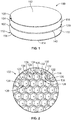
- FIG. 1 is a top perspective view of a composite sound-absorbing panel assembly 100 according to an embodiment of the present disclosure.
- the composite sound-absorbing panel assembly 100 is referred to herein as composite panel 100 and panel 100.
- the panel 100 includes an acoustic meta-structure 102 sandwiched between a first elastic membrane 104 and a second elastic membrane 106.
- the acoustic meta-structure 102 also referred to herein simply as structure 102 or meta-structure 102, has top side 108 and a bottom side 110 that is opposite to the top side 108.
- the top side 108 is mounted to the first elastic membrane 104.
- the bottom side 110 is mounted to the second elastic membrane 106.
- the top side 108 may be referred to as a first side or a second side, and the bottom side 110 may be referred to as a second side or a first side.
- top bottom
- upper lower
- vertical vertical
- the panel 100 has a height extending from an exterior surface 112 of the first elastic membrane 104 to an exterior surface 114 of the second elastic membrane 106.
- the exterior surfaces 112, 114 of the membranes 104, 106 face away from each other.
- the panel 100 has a round disc-shape, as the first and second elastic membranes 104, 106 are generally planar.
- the panel 100 may be formed into various other shapes in other embodiments, such as rectangular or square tiles, sheets, films, or the like.
- the meta-structure 102 includes an upper honeycomb layer 116, a lower honeycomb layer 118, and an intermediate space 120 therebetween.
- Each of the upper and lower honeycomb layers 116, 118 represents a lattice of interconnected cells distributed in a two-dimensional plane, as shown in Figure 2 .
- the upper honeycomb layer 116 is spaced apart from the lower honeycomb layer 118 by the intermediate space 120.
- the upper honeycomb layer 116 is physically connected to the lower honeycomb layer 118 via interconnecting necks 206 (shown in Figure 3 ) that extend across the intermediate space 120.
- the upper honeycomb layer 116 may be referred to as a first honeycomb layer or a second honeycomb layer, and the lower honeycomb layer 118 may be referred to as a second honeycomb layer or a first honeycomb layer.
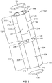
- FIG 2 is a perspective top-down view of the meta-structure 102 of the panel 100 according to an embodiment.
- the first elastic membrane 104 is omitted to show the upper honeycomb layer 116 (also referred to herein simply as upper layer 116) of the meta-structure 102 in detail.
- the upper layer 116 has partition walls 122 that define a honeycomb-like lattice of interconnected cells 124.
- the upper layer 116 is also referred to herein as an upper honeycomb layer 116.
- the cells 124 are arranged side-by-side in a two-dimensional plane. For example, each cell 124 extends a full height of the upper layer 116 between the first elastic membrane 104 and the intermediate space 120 (shown in Figure 1 ).
- Each cell 124 includes a respective resonance cavity 126 that is defined between the partition walls 122 of the cell 124.
- many of the partition walls 122 extend between and define portions of two cavities 126 of adjacent cells 124.
- the resonance cavities 126 in the illustrated embodiment are hexagonal cavities that are each defined by six partition walls 122.
- the resonance cavities 126 may have different numbers of sides in other embodiments.
- at least some of the cavities 126 may be pentagonal or octagonal in other embodiments.
- the partition walls 122 of the upper layer 116 may be referred to as first partition walls or second partition walls.
- the resonance cavities 126 each extend between an outer end 128 and an inner end 130 opposite to the outer end 128.
- the outer ends 128 of the resonance cavities 126 are located at distal edges 132 of the partition walls 122. With additional reference to Figure 1 , the distal edges 132 of the partition walls 122 define the top side 108 of the meta-structure 102.
- the inner ends 130 of the resonance cavities 126 are proximate to the intermediate space 120.
- the resonance cavities 126 are open at the outer ends 128.
- the first elastic membrane 104 covers the outer ends 128 of the resonance cavities 126 of the upper layer 116, enclosing and sealing the cavities 126.
- the upper honeycomb layer 116 includes a base wall 134 that defines the inner ends 130 of the resonance cavities 126.
- the partition walls 122 are coupled to the base wall 134 and extend vertically from the base wall 134 to the distal edges 132.
- the base wall 134 generally encloses the inner ends 130 of the cavities 126, except for small orifices 136 that extend through the base wall 134.
- Each orifice 136 aligns with a different one of the resonance cavities 126.
- Each cavity 126 is fluidly connected to a single orifice 136 in the base wall 134 such that air may pass to and through the orifice 136.
- more than one orifice 136 may align with at least some of the resonance cavities 126, or some resonance cavities 126 may not align with any orifices 136 in the base wall 134.
- the lower honeycomb layer 118 (also referred to herein simply as lower layer 118) that is shown in Figure 1 may be identical, or at least substantially similar, in design, size, and shape as the upper layer 116, such that the lower layer 118 is also a honeycomb lattice of interconnected cells.
- the lower layer 118 mirrors the upper layer 116.
- the intermediate space 120 ( Figure 1 ) is defined between the base wall 134 of the upper layer 116 and a base wall 140 ( Figure 1 ) of the lower layer 118. Additional details of the lower honeycomb layer 118 are provided herein with reference to Figures 3 and 4 .
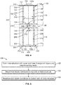
- Figure 3 is an exploded perspective view of a unit module 202 of the meta-structure 102 and portions of the first and second elastic membranes 104, 106 that align with the unit module 202 according to an embodiment.
- the unit module 202 of the meta-structure 102 includes one cell 124 of the upper layer 116, one cell 204 of the lower layer 118, and a neck 206 interconnecting the two cells 124, 204.
- the cell 204 of the lower layer 118 has an identical, or at least substantially similar, design, size, and shape as the cell 124.
- two components are considered as "identical” herein if the two components are intended to have the same design, shape, and size, even though the identical components may have different blemishes or imperfections.
- the cell 204 includes partition walls 208 that define a resonance cavity 210 (shown in Figure 4 ).
- the cell 204 mirrors the cell 124 on opposite ends of the neck 206.
- the partition walls 208 of the lower layer 118 may be referred to as second partition walls or first partition walls.
- the unit module 202 extends the full height of the meta-structure 102 between the top and bottom sides 108, 110.
- distal edges 212 of the partition walls 208 define a portion of the bottom side 110 of the meta-structure 102.
- the unit module 202 is a structure that is repeated many times within the meta-structure 102.
- the meta-structure 102 may be formed by tessellating, or replicating, the unit module 202 side-by-side in a two-dimensional plane.
- the unit module 202 is illustrated as a discrete, unitary structure in Figure 3 for descriptive purposes, but, as shown in Figure 2 , the cell 124 of the unit module 202 may be integrally connected to adjacent cells 124 in the upper layer 116.
- the cell 204 of the unit module 202 may be integrally connected to adjacent cells (not shown) in the lower layer 118.
- the neck 206 is connected to each of the cells 124, 204 and extends between the cells 124, 204 across the intermediate space 120.
- the neck 206 is coupled to the base wall 140 of the lower cell 204 and the base wall 134 (shown in Figure 2 ) of the upper cell 124.
- the neck 206 has a smaller diameter than the cells 124, 204.
- the volume of the intermediate space 120 between the cells 124, 204 surrounding the neck 206 is occupied by air or another fluid.
- the meta-structure 102 in a non-limiting embodiment is composed of a polymeric material, such as one or more plastics or other polymers.
- the meta-structure 102 is composed of a polyamide material.
- the meta-structure 102 in other embodiments may be composed of other materials, such as metallic materials, composite materials, ceramics, or the like. For example, constructing the meta-structure 102 using ceramics or other heat-resistant materials may allow the meta-structure 102 to be installed at a high-temperature environment, such as near an engine of an aircraft.
- the first and second elastic membranes 104, 106 may be composed of a rubber material.
- rubber material as used herein is inclusive of both natural rubber and synthetic, rubber-like materials.
- the membranes 104, 106 are configured to oscillate relative to the meta-structure 102 due to sound waves and/or other pressure fluctuations.
- the elastic membranes 104, 106 may be composed of materials other than rubber materials, such as a metallic material, a composite material, or the like.
- the neck 206 is integrally connected to both the upper cell 124 and the lower cell 204.
- the meta-structure 102 is produced via an additive manufacturing process, such as 3D printing, vapor fusion deposition, or the like.
- the upper cells 124 of the upper layer 116, the lower cells 204 of the lower layer 118, and the necks 206 are formed during a common manufacturing process.
- the upper layer 116, the lower layer 118, and the necks 206 are formed integral with each other during the additive manufacturing process.
- the upper layer 116, the lower layer 118, and necks 206 are each formed as separate and discrete components in different processes, and the integral connection between the components may be accomplished by permanently bonding the components to one another after formation, such as through pasting, welding, or brazing.
- the upper and lower layers 116, 118 may each be formed via an additive manufacturing process, and the necks 206 may be molded cylinders that are subsequently welded between the upper and lower layers 116, 118.
- the permanent bonding process such as brazing or welding, integrally connects the upper and lower layers 116, 118 to the necks 206, resulting in a unitary, one-piece meta-structure 102 (comparable to forming the entire meta-structure 102 during a common additive manufacturing process).
- the first elastic membrane 104 may be bonded to the distal edges 132 of the partition walls 122 to mount the membrane 104 to the upper layer 116.
- the elastic membrane 104 covers the outer end 128 of the resonance cavity 126 to seal the resonance cavity 126.
- the elastic membrane 104 may bond to the distal edges 132 using an adhesive, such as an epoxy.
- the second elastic membrane 106 may be similarly bonded to the distal edges 212 of the partition walls 208 to mount the membrane 106 to the lower layer 118.
- first and second elastic membranes 104, 106 are shown in Figure 3 as hexagonal discs with sizes that correspond to the diameters of the cells 124, 204 of the unit module 202, the illustrated hexagonal discs may be merely segments of larger membranes 104, 106 that align with the unit module 202.
- the elastic membranes 104, 106 may cover an entire area of the meta-structure 102.
- the partition walls 122 of the cells 124 in the upper layer 116 are sized to have a length 216 within a designated range.
- the length 216 is the dimension extending across the given partition wall 122 between the two corners 214 that connect that partition wall 122 to adjacent partition walls 122.
- the length 216 of the partition wall 122 is between about 1 mm and about 6 mm.
- all of the partition walls 122 of the upper layer 116 have approximately the same length 216.
- modifying a value representative of a measurement such as “approximately” and “about” means that the measurement is inclusive of the stated value as well as values above and below the stated value within a designated threshold range, which may be 1%, 3%, or 5% of the stated value.
- a designated threshold range which may be 1%, 3%, or 5% of the stated value.
- deviations in dimensions may result from variability in production and processing, and such deviations are considered within the scope of the specified ranges disclosed herein.
- the length 216 of the partition walls 122 may affect the sound absorbing qualities of the composite panel 100 ( Figure 1 ). Because the cell 204 of the lower layer 118 is a mirrored replica of the cell 124, the partition walls 208 of the cell 204 may have the same dimensions (e.g., including length) as the partition walls 122 of the cell 124.
- Figure 4 is a transverse cross-sectional view of a portion of the composite panel 100 according to an embodiment.
- the illustrated portion shows one full unit module 202 of the acoustic meta-structure 102 and small segments of adjacent unit modules 202.
- the neck 206 of the meta-structure 102 is hollow and defines a channel 302 through the neck 206.
- the channel 302 is fluidly connected to both of the resonance cavities 126, 210 at the ends of the neck 206.
- the channel 302 is fluidly connected to the resonance cavity 126 in the upper cell 124 through the orifice 136 in the base wall 134.
- the channel 302 is fluidly connected to the resonance cavity 210 in the lower cell 204 through an orifice 304 in the base wall 140.
- the channel 302 provides a fluid path across the intermediate space 120 between the two resonance cavities 126, 210.
- the channel 302 has a smaller diameter than the diameters of the two resonance cavities 126, 210.
- the meta-structure 102 is configured to function as a dual Helmholtz resonator based on the narrow channel 302 that connects two larger cavities 126, 210.
- the first and second elastic membranes 104, 106 are configured to oscillate (e.g., vibrate) relative to the meta-structure 102 in response to pressure fluctuations.
- the membranes 104, 106 each move reciprocally outwards (e.g., away from the neck 206) and inwards (e.g., towards the neck 206).
- the first and second membranes 104, 106 may have in-phase displacement, and the first and second membranes 104, 106 may have out-of-phase displacement at other frequencies.
- the illustrated embodiment shows an example of in-phase displacement of the membranes 104, 106 in phantom.
- the phantom displacement 104a of the first elastic membrane 104 bulges outward away from the hexagonal resonance cavity 126 and the phantom displacement 106a of the second elastic membrane 106 bends inward into the hexagonal resonance cavity 210.
- the partition walls 122, 208 of the meta-structure 102 may also be configured to bend, flex, and/or twist in response to pressure fluctuations.
- the movement of the partition walls 122 of the upper honeycomb layer 116 may transfer vibrational energy between adjacent hexagonal resonance cavities 126
- the movement of the partition walls 208 of the lower honeycomb layer 118 may transfer vibrational energy between adjacent hexagonal resonance cavities 210.
- the physical parameters of the composite panel 100 affect the sound-absorbance or sound transmission loss of the composite panel 100, including the magnitude of sound transmission loss and the frequency ranges that are absorbed.
- the parameters of the meta-structure 102 and the membranes 104, 106 can be customized in order to tune the composite panel 100 for desired sound-absorbing properties as well as for desired applications (e.g., as a film or a tile).
- the ranges of various parameters presented below are non-limiting example ranges only.
- the neck 206 has a height 310 extending from the upper honeycomb layer 116 to the lower honeycomb layer 118 that is between about 0.2 mm and about 2 mm.
- the channel 302 of the neck 206 has a diameter 312 that is also between about 0.2 mm and about 2 mm.
- the partition walls 122 of the upper honeycomb layer 116 may have a thickness 314 that is also between about 0.2 mm and about 2 mm.
- the hexagonal resonance cavities 126 have a diameter 316 defined between parallel, opposing partition walls 122 that may be between about 3 mm and about 12 mm.
- the partition walls 208 of the lower honeycomb layer 118 may have the same thickness 314 as the partition walls 122.
- the hexagonal resonance cavities 210 of the lower honeycomb layer 118 may have the same diameter 316 as the cavities 126.
- the base walls 134, 140 of the meta-structure 102 may have the same or similar thicknesses as the partition walls 122, 208.
- the height 310 of the neck 206 is about 1 mm
- the diameter 312 of the channel 302 is about 0.5 mm
- the thickness 314 of the partition walls 122, 208 is about 0.5 mm
- the diameter 316 of the resonance cavities 126, 210 is about 7 mm.
- the first elastic membrane 104 has a thickness 318 defined between the exterior surface 112 and an interior surface 320 of the membrane 104 that is opposite to the exterior surface 112.
- the thickness 318 may be between about 0.1 mm and about 2 mm.
- the second elastic membrane 106 has a thickness 322 defined between the exterior surface 114 and an interior surface 324 of the membrane 106.
- the second elastic membrane 106 may be identical or at least substantially similar to the first elastic membrane 104, such that the thickness 322 may be the same as the thickness 318.
- the thicknesses 318, 322 of the membranes 104, 106 are about 0.25 mm.
- the meta-structure 102 has a height 326 that extends from the top side 108 to the bottom side 110.
- the height 326 is the cumulative sum of the respective heights of the partition walls 122 and 208, the respective thicknesses of the base walls 134 and 140, and the height 310 of the neck 206.
- the height 326 of the meta-structure 102 may be between about 4 mm and about 30 mm. In a non-limiting example, the height 326 is about 24 mm, but the meta-structure 102 may be formed to have different height parameters based on the application of the composite panel 100.
- the meta-structure 102 may have a condensed height of around 8 mm or less (e.g., when the composite panel 100 is implemented as a thin film-like sheet). In other embodiments, the height may be greater (e.g., when the composite panel 100 is implemented as a tile or a self-supported wall panel).
- a composite sound-absorbing panel was constructed according to the embodiments shown in Figures 1-4 , and the panel was experimentally tested to determine sound-absorbing performance of the panel.
- the meta-structure of the composite panel was composed of a polyamide material, and the two elastic membranes were composed of natural rubber.
- the two elastic membranes each had a thickness of 0.25 mm.
- the meta-structure had a height between the two membranes of 24 mm.
- the side length of the partition walls was 3.5 mm, and the thickness of the partition walls was 0.5 mm.
- the height of the necks between the upper and lower honeycomb layers was 1 mm.
- the diameter of the channels of the necks was 0.5 mm.
- the diameter of the hexagonal resonance cavities was 7 mm.
- the sound transmission loss (STL) of the composite panel was measured using a standardized impedance tube test.
- the composite panel had an average STL of 57 dB in a low frequency range of 25-500 Hz.
- the low frequency range may be experienced by a passenger within an interior cabin of an aircraft, for example.
- the results indicate that the composite panel provides better sound dampening in the low frequency range than known sound-absorbing materials.
- the composite panel Throughout a larger frequency range of 25-1600 Hz, the composite panel had a measured average STL of 37 dB.
- the resonant frequencies were observed at 708 Hz and 1168 Hz, and the absorption coefficients at these resonant frequencies were 0.78 and 0.91.
- Simulations of the composite panel were also performed.
- the simulations indicated that sound attenuation is accomplished by vibration of the membranes relative to the meta-structure, and also by inter-cavity coupling of vibrational energy due to bending and flexing of the partition walls.
- the simulations estimated that the composite panel has a negative effective bulk modulus in the frequency range of 1105 to 1545 Hz.
- the negative effective bulk modulus may be due to monopolar resonance created by the Helmholtz resonator of the meta-structure and out-of-phase movement of the first and second elastic membranes.
- the simulations also estimated that the composite panel has a negative effective dynamic mass in a frequency range of 745 to 1525 Hz.
- the negative effective dynamic mass may be due to dipolar resonance created by the in-phase movement of the membranes.
- the simulations estimated that there is a double negative region where the two frequency ranges overlap, which in this case is between 1105 Hz and 1525 Hz.
- the double negative region is indicative of a combination of both in-phase and out-of-phase movement of the elastic membranes.
- the height of the meta-structure has little effect on the sound absorbance properties of the composite panel. Therefore, the height of the composite panel can be customized based on the application without significantly affecting the performance of the panel.
- Figure 5 is a flow chart of a method 400 for producing a composite sound-absorbing panel according to an embodiment.
- the composite sound-absorbing panel produced by the method 400 may be installed within an interior cabin of a vehicle to provide noise dampening, or may be installed proximate to a noise emitter, such as an engine of a vehicle.
- the composite sound-absorbing panel may also be installed outside of vehicles, such as in factories or homes.
- the method 400 may produce one or more of the embodiments of the composite panel 100 shown in Figures 1-4 .
- an acoustic meta-structure is formed.
- the acoustic meta-structure may be formed via an additive manufacturing process, but is not limited to formation via additive manufacturing.
- the additive manufacturing process may be 3D printing, selective laser sintering, fused deposition modeling, or the like.
- the meta-structure may be formed using a polymeric material, such as polyamide or the like.
- the meta-structure is formed to have a specific architecture.
- the meta-structure includes an upper honeycomb layer and a lower honeycomb layer.
- Each of the honeycomb layers is a lattice that includes partition walls that define resonance cavities between the partition walls.
- the resonance cavities of the upper and lower honeycomb layers have hexagonal cross-sections, such that each resonance cavity is defined between six partition walls.
- the upper and lower honeycomb layers each include a respective base wall from which the partition walls extend. Each partition wall extends from the base wall to a distal edge of the partition wall.
- the upper and lower honeycomb layers mirror each other such that the base walls are proximate to each other, the distal edges of the partition walls of the upper honeycomb layer define a top side of the meta-structure, and the distal edges of the partition walls of the lower honeycomb layer define a bottom side of the meta-structure.
- Each of the resonance cavities extends from an inner end at the respective base wall to an outer end at the distal edges of the respective partition walls.
- the necks are disposed between the upper and lower honeycomb layers.
- the necks extend between and connect the base walls of the upper and lower honeycomb layers.
- the upper honeycomb layer is connected to the lower honeycomb layer through the necks.
- the necks define channels that have smaller diameters than the resonance cavities.
- Each of the channels fluidly connects one of the resonance cavities of the upper honeycomb layer to one of the resonance cavities of the lower honeycomb layer.
- the channels of the necks align with orifices in the base walls to provide the fluid connection between the resonance cavities.
- the additive manufacturing process may form the upper honeycomb layer, the necks, and the lower honeycomb layer during a common formation process such that all three sections of the meta-structure are integrally formed and integrally connected to one another.
- a first elastic membrane is mounted to the top side of the meta-structure.
- the elastic membrane may be a thin sheet composed of a rubber material, a metal material, a composite material, or the like.
- the elastic membrane may be mounted to the top side by bonding the elastic membrane to the distal edges of the partition walls of the upper honeycomb layer.
- the elastic membrane may be bonded to the partition walls using an adhesive, such as a thermally-curable epoxy.
- the mounting operation may be accomplished by applying the thermally-curable epoxy to the distal edges of the partition walls while the epoxy is in a flowable state, then positioning the elastic membrane on the distal edges of the partition walls.
- the assembly is heated to cure or set the epoxy, which provides a permanent bond between the membrane and the distal edges of the partition walls.
- the elastic membrane may be bonded to the partition walls via brazing, welding, or the like, such as when the elastic membrane is a thin metallic sheet.
- a second elastic membrane is mounted to the bottom side of the meta-structure.
- the second elastic membrane may be identical or at least substantially similar to the first elastic membrane.
- the second elastic membrane may be mounted to the distal edges of the partition walls of the lower honeycomb layer in the same or a similar way that the first elastic membrane is mounted to the upper honeycomb layer, such as via a thermally-curable epoxy or another adhesive.
- the second elastic membrane covers and seals the outer ends of the resonance cavities of the lower honeycomb layer.
- the meta-structure may be formed by molding or additively manufacturing individual cells defining a single resonance cavity.
- the cells are subsequently secured to one another side-by-side to define a cell lattice similar to each of the upper and lower honeycomb layers.
- each of the upper and lower honeycomb layers can be produced as assemblies of multiple identical sub-units instead of being unitary structures integrally-formed during a single additive manufacturing process.
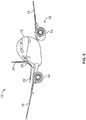
- FIG. 6 illustrates a front perspective view of an aircraft 10 according to an embodiment of the present disclosure.
- the aircraft 10 includes a propulsion system 12 that may include two turbofan engines 14, for example.
- the propulsion system 12 may include more engines 14 than shown.
- the engines 14 are carried by wings 16 of the aircraft 10.
- the engines 14 may be carried by a fuselage 18 and/or an empennage 20.
- the empennage 20 may also support horizontal stabilizers 22 and a vertical stabilizer 24.
- the fuselage 18 of the aircraft 10 defines an interior cabin.
- Figure 7 illustrates a top plan view of an interior cabin 30 of the aircraft 10 (shown in Figure 6 ) according to an embodiment of the present disclosure.
- the interior cabin 30 is within the fuselage 18.
- one or more fuselage wall members 62 may define the interior cabin 30.
- the interior cabin 30 includes multiple sections or zones, including a front section 33, a first class section 34, a business class section 36, a front galley station 38, a business section 40 (e.g., an expanded economy or coach section), a standard economy or coach section 42, and an aft section 44, which may include multiple lavatories and galley stations. It is to be understood that the interior cabin 30 may include more or less sections and zones than shown.
- the interior cabin 30 may not include a first class section, and may include more or less galley stations than shown.
- Each of the sections may be separated by a cabin transition area 46, which may include class divider assemblies.
- Overhead stowage bin assemblies may be positioned throughout the interior cabin 30.
- the interior cabin 30 includes two aisles 50 and 52 that lead to the aft section 44.
- the interior cabin 30 may have less or more aisles than shown.
- the interior cabin 30 may include a single aisle that extends through the center of the interior cabin 30 that leads to the aft section 44.
- the interior cabin 30 includes rows 53 of seats 54 that span across the interior cabin 30 and generally extend across the aisles 50 and 52. Columns 55, 57, and 59 of seat sections extend perpendicular to the rows 53.
- Each seat section may include one or more seats 54.
- the columns 55, 57, and 59 generally run parallel with the aisles 50 and 52.
- a particular section or zone may include any number of columns 55, 57, and 59 of seat sections. As shown in Figure 7 , at least one zone includes three columns 55, 57, and 59 of seat sections. However, each zone may include more or less than three columns.
- the interior cabin 30 may include composite sound-absorbing panels formed according to one or more of the embodiments described herein.
- the composite sound-absorbing panels may be mounted along the fuselage wall members 62. Additionally, or alternatively, the composite sound-absorbing panels may be positioned proximate to the engines 14 (shown in Figure 6 ) to shield the interior cabin 30 from the engine noise.
- the composite sound-absorbing panels may be configured to absorb and attenuate low-frequency noise to reduce the level of engine noise within the interior cabin 30.
- embodiments of the composite sound-absorbing panels may be used with various other vehicles, such as automobiles, buses, locomotives and train cars, seacraft, spacecraft, and the like.
- a structure, limitation, or element that is "configured to” perform a task or operation is particularly structurally formed, constructed, or adapted in a manner corresponding to the task or operation.
- an object that is merely capable of being modified to perform the task or operation is not “configured to” perform the task or operation as used herein.
Landscapes
- Engineering & Computer Science (AREA)
- Physics & Mathematics (AREA)
- Acoustics & Sound (AREA)
- Multimedia (AREA)
- Mechanical Engineering (AREA)
- Aviation & Aerospace Engineering (AREA)
- Soundproofing, Sound Blocking, And Sound Damping (AREA)
- Laminated Bodies (AREA)
- Building Environments (AREA)
Description
- Embodiments of the present disclosure generally relate to composite sound-absorbing panel assemblies, and, more particularly, to acoustic structures configured to absorb sound at tunable frequency ranges to dampen noise within, for example, interior cabins of vehicles, such as aircraft.
- Sound-absorbing materials are desirable in various vehicles and facilities with people present because exposure to high noise levels can cause hearing loss, increase stress, and interfere with communication. Some current types of noise dampening materials include active noise cancelling piezo-electric materials and passive foams and foam-like materials, but each has associated disadvantages. For example, weight and space are concerns for the passive foam materials, which are typically relatively heavy and voluminous. Heavy foam installed within certain vehicles, such as aircraft, may result in increased fuel consumption and reduced operating efficiency. Another disadvantage of passive foam materials is that the materials are typically not designed to absorb sound at frequency ranges of interest that are specific to a certain application. The piezo-based systems may be smaller and/or lighter than the foams, but require hardware, such as electrical components, circuitry, and power supplies. The piezo-based systems are generally more complex and costly to manufacture, install, operate, troubleshoot, and repair than the passive foams, and reliability of the systems can also be an issue.
-
EP3135949 , in accordance with its abstract, states a deformable structure, such as a panel or a shock absorber, for absorbing energy from a mechanical and/or acoustic impact comprising an inner core and one or more external layers covering the inner core. The inner core comprises a set of first segments having a positive Poison's ratio and second segments having a negative Poisson's ratio. The first and second segments are arranged alternately and joined between them so that the deformation received by one first segment can be transmitted to an adjacent second segment and vice versa. - A need exists for a sound-absorbing panel that effectively dampens noise within a frequency range of interest and can be installed in a vehicle, such as an aircraft. A need exists for an efficient way of constructing such a sound-absorbing panel.
- With those needs in mind, certain embodiments of the present disclosure provide a composite panel assembly configured to absorb sound.
- There is described herein a composite panel assembly comprising: first and second elastic membranes; and a structure having a first side and a second side that is opposite the first side, the first side mounted to the first elastic membrane, the second side mounted to the second elastic membrane, the structure comprising: a first honeycomb layer with partition walls defining resonance cavities, the resonance cavities of the first honeycomb layer covered by the first elastic membrane along the first side of the structure; a second honeycomb layer with partition walls defining resonance cavities, the resonance cavities of the second honeycomb layer covered by the second elastic membrane along the second side of the structure; and a plurality of necks disposed between and connecting the first and second honeycomb layers, each neck defining a respective channel that is fluidly connected to a corresponding one of the resonance cavities of the first honeycomb layer and a corresponding one of the resonance cavities of the second honeycomb layer.
- There is also described herein a method comprising: forming a structure having a first side and a second side that is opposite to the first side, the structure including a first honeycomb layer with partition walls defining resonance cavities, a second honeycomb layer with partition walls defining resonance cavities, and a plurality of necks disposed between and connecting the first and second honeycomb layers, each neck defining a channel that is fluidly connected to a corresponding one of the resonance cavities of the first honeycomb layer and a corresponding one of the resonance cavities of the second honeycomb layer; mounting a first elastic membrane to the first side of the structure, the first elastic membrane covering outer ends of the resonance cavities of the first honeycomb layer; and mounting a second elastic membrane to the second side of the structure, the second elastic membrane covering outer ends of the resonance cavities of the second honeycomb layer.
- As further described herein, the resonance cavities of the first and second honeycomb layers are hexagonal cavities, and each hexagonal cavity is defined by six partition walls. Optionally, the length of the partition walls between adjacent partition walls is between about 1 mm and about 6 mm.
- As further described herein, each of the first honeycomb layer and the second honeycomb layer includes a respective base wall that defines inner ends of the respective resonance cavities. The necks extend between and connect the two base walls of the first and second honeycomb layers. Each of the base walls defines orifices therethrough that align with the channels of the necks to fluidly connect the resonance cavities of the first honeycomb layer to the resonance cavities of the second honeycomb layer through the channels.
- As further described herein, a thickness of each of the first and second elastic membranes between an interior surface and an exterior surface is between about 0.1 mm and about 1.0 mm. The necks may each have a length that is between about 0.2 mm and about 2 mm. The structure may have a height between the first side and the second side that is between about 5 mm and about 30 mm.
- Further examples of the present disclosure provide a composite panel assembly configured to absorb sound. The panel assembly includes a structure having multiple unit modules disposed side by side. Each of the unit modules includes a first base wall and multiple first partition walls extending from the first base wall to define a first resonance cavity. The first base wall defines an inner end of the first resonance cavity. Each unit module also has a second base wall and multiple second partition walls extending from the second base wall to define a second resonance cavity. The second base wall defines an inner end of the second resonance cavity. The second base wall is spaced apart from the first base wall. Each unit module includes a neck extending between and connecting the first and second base walls. The neck defines a channel therethrough that is fluidly connected to the first resonance cavity through an orifice in the first base wall and is fluidly connected to the second resonance cavity through an orifice in the second base wall.
- These and other features, aspects, and advantages of the present disclosure will become better understood when the following detailed description is read with reference to the accompanying drawings in which like numerals represent like parts throughout the drawings, wherein:
-
Figure 1 is a top perspective view of a composite sound-absorbing panel assembly according to an embodiment of the present disclosure; -
Figure 2 is a perspective top-down view of an acoustic meta-structure of the composite panel assembly according to an embodiment of the present disclosure; -
Figure 3 is an exploded perspective view of a unit module of the acoustic meta-structure and portions of first and second elastic membranes that align with the unit module according to an embodiment of the present disclosure; -
Figure 4 is a transverse cross-sectional view of a portion of the composite panel assembly according to an embodiment of the present disclosure; -
Figure 5 is a flow chart of a method for producing a composite sound-absorbing panel assembly according to an embodiment of the present disclosure; -
Figure 6 illustrates a front perspective view of an aircraft according to an embodiment of the present disclosure; and -
Figure 7 illustrates a top plan view of an interior cabin of the aircraft ofFigure 6 . - The foregoing summary, as well as the following detailed description of certain embodiments will be better understood when read in conjunction with the appended drawings. As used herein, an element or step recited in the singular and preceded by the word "a" or "an" should be understood as not necessarily excluding the plural of the elements or steps. Further, references to "one embodiment" are not intended to be interpreted as excluding the existence of additional embodiments that also incorporate the recited features. Moreover, unless explicitly stated to the contrary, embodiments "comprising" or "having" an element or a plurality of elements having a particular property may include additional elements not having that property.
- Certain embodiments of the present disclosure provide a scalable composite panel assembly for sound-absorption that can be used within a vehicle, such as a commercial aircraft, as well as within various facilities, such as manufacturing plants, factories, offices, and the like. The composite panel assemblies of the embodiments described herein may be produced in the form of tiles, films, wall panels, or the like, and can be selectively sized to cover desired areas for noise dampening.
- The composite panel assembly described in one or more embodiments herein has a structural architecture that includes an acoustic meta-structure disposed between two elastic membranes. The term "acoustic meta-structure" refers to a structure that is designed to passively control, direct, and manipulate sound waves that impinge upon the structure based on the specific architecture of the structure. The acoustic meta-structure may include twin layers of honeycomb-shaped cavities, and the cavities in the two layers are interconnected through small channels within neck portions of the meta-structure. Each of the two elastic membranes extends across and covers the honeycomb-shaped cavities of a different one of the layers. When exposed to sound waves, the membranes vibrate, moving into and out of the honeycomb-shaped cavities. In addition, partition walls of the meta-structure that define the cavities may bend and flex due to the vibrational energy. The honeycomb-shaped cavities in the twin layers function as resonance chambers, and the interconnecting channels between two cavities allow the meta-structure to represent a dual Helmholtz resonator.
- The embodiments of the composite panel assembly described herein can have parameters that are tuned to provide certain desired acoustic properties. For example, the composite panel assembly may provide relatively high sound transmission loss at a frequency range of interest, such as at low frequencies (e.g., 25 - 500 Hz) present within interior cabins of aircraft and/or at higher frequencies. The composite panel assembly may be configured such that there is a first range of frequencies in which the panel assembly has a negative bulk modulus, and a second range of frequencies in which the panel assembly has a negative mass density. The first and second frequency ranges may overlap to define a "double negative" frequency range in which both the bulk modulus and the mass density are negative. The composite panel assembly demonstrates high sound transmission loss and a high absorption coefficient in desirable frequency ranges.
- In one or more embodiments, the composite sound-absorbing panel assembly can be produced via relatively cost efficient and simple manufacturing methods. For example, the acoustic meta-structure can be assembled via an additive manufacturing process, such as 3D printing or the like, using one or more polymeric materials. The membranes can then be bonded to opposite first and second sides of the meta-structure. The manufacturing process is highly scalable and the resulting panel assembly can be used in large area noise shielding applications. For example, the panel assembly can be placed on walls within an interior cabin of an aircraft, within an engine compartment of an aircraft to surround the engine (e.g., cowl, nacelle, and the like), or other locations in which sound or vibrations may be undesired. The panel assembly optionally may be constructed using heat-resistant materials.
- Additionally, the panel assemblies may be made to have an application-specific thickness without significantly affecting the sound absorbing properties of the panels. Thus, the thickness of the panel assembly may be selectable within a given range, such as between about 3 mm and about 30 mm. The relatively large range of allowable thicknesses provides options in how the composite panel assembly is implemented within an application. For example, the composite panel assembly may be formed as interconnecting panels, as tiles, or as a film or coating that is applied onto a flat surface (e.g., similar to wallpaper).
-
Figure 1 is a top perspective view of a composite sound-absorbingpanel assembly 100 according to an embodiment of the present disclosure. The composite sound-absorbingpanel assembly 100 is referred to herein ascomposite panel 100 andpanel 100. Thepanel 100 includes an acoustic meta-structure 102 sandwiched between a firstelastic membrane 104 and a secondelastic membrane 106. - The acoustic meta-
structure 102, also referred to herein simply asstructure 102 or meta-structure 102, hastop side 108 and abottom side 110 that is opposite to thetop side 108. Thetop side 108 is mounted to the firstelastic membrane 104. Thebottom side 110 is mounted to the secondelastic membrane 106. Thetop side 108 may be referred to as a first side or a second side, and thebottom side 110 may be referred to as a second side or a first side. - While various spatial and directional terms, such as "top," "bottom," "upper," "lower," "vertical," and the like may be used to describe embodiments of the present disclosure, it is understood that such terms are merely used with respect to the orientations shown in the drawings. The orientations may be inverted, rotated, or otherwise changed, such that the
top side 108 becomes a bottom side if the meta-structure 102 is flipped 180 degrees, becomes a left side or a right side if the meta-structure 102 is pivoted 90 degrees, and the like. - The
panel 100 has a height extending from anexterior surface 112 of the firstelastic membrane 104 to anexterior surface 114 of the secondelastic membrane 106. The exterior surfaces 112, 114 of themembranes panel 100 has a round disc-shape, as the first and secondelastic membranes panel 100 may be formed into various other shapes in other embodiments, such as rectangular or square tiles, sheets, films, or the like. - The meta-
structure 102 includes anupper honeycomb layer 116, alower honeycomb layer 118, and anintermediate space 120 therebetween. Each of the upper and lower honeycomb layers 116, 118 represents a lattice of interconnected cells distributed in a two-dimensional plane, as shown inFigure 2 . Theupper honeycomb layer 116 is spaced apart from thelower honeycomb layer 118 by theintermediate space 120. Theupper honeycomb layer 116 is physically connected to thelower honeycomb layer 118 via interconnecting necks 206 (shown inFigure 3 ) that extend across theintermediate space 120. Theupper honeycomb layer 116 may be referred to as a first honeycomb layer or a second honeycomb layer, and thelower honeycomb layer 118 may be referred to as a second honeycomb layer or a first honeycomb layer. -
Figure 2 is a perspective top-down view of the meta-structure 102 of thepanel 100 according to an embodiment. The firstelastic membrane 104 is omitted to show the upper honeycomb layer 116 (also referred to herein simply as upper layer 116) of the meta-structure 102 in detail. Theupper layer 116 haspartition walls 122 that define a honeycomb-like lattice ofinterconnected cells 124. Theupper layer 116 is also referred to herein as anupper honeycomb layer 116. Thecells 124 are arranged side-by-side in a two-dimensional plane. For example, eachcell 124 extends a full height of theupper layer 116 between the firstelastic membrane 104 and the intermediate space 120 (shown inFigure 1 ). Eachcell 124 includes arespective resonance cavity 126 that is defined between thepartition walls 122 of thecell 124. In the illustrated embodiment, many of thepartition walls 122 extend between and define portions of twocavities 126 ofadjacent cells 124. The resonance cavities 126 in the illustrated embodiment are hexagonal cavities that are each defined by sixpartition walls 122. Optionally, theresonance cavities 126 may have different numbers of sides in other embodiments. For example, at least some of thecavities 126 may be pentagonal or octagonal in other embodiments. Thepartition walls 122 of theupper layer 116 may be referred to as first partition walls or second partition walls. - The resonance cavities 126 each extend between an
outer end 128 and aninner end 130 opposite to theouter end 128. The outer ends 128 of theresonance cavities 126 are located atdistal edges 132 of thepartition walls 122. With additional reference toFigure 1 , thedistal edges 132 of thepartition walls 122 define thetop side 108 of the meta-structure 102. The inner ends 130 of theresonance cavities 126 are proximate to theintermediate space 120. The resonance cavities 126 are open at the outer ends 128. When assembled into thepanel 100 shown inFigure 1 , the firstelastic membrane 104 covers the outer ends 128 of theresonance cavities 126 of theupper layer 116, enclosing and sealing thecavities 126. - The
upper honeycomb layer 116 includes abase wall 134 that defines the inner ends 130 of theresonance cavities 126. Thepartition walls 122 are coupled to thebase wall 134 and extend vertically from thebase wall 134 to thedistal edges 132. Thebase wall 134 generally encloses the inner ends 130 of thecavities 126, except forsmall orifices 136 that extend through thebase wall 134. Eachorifice 136 aligns with a different one of theresonance cavities 126. Eachcavity 126 is fluidly connected to asingle orifice 136 in thebase wall 134 such that air may pass to and through theorifice 136. Alternatively, more than oneorifice 136 may align with at least some of theresonance cavities 126, or someresonance cavities 126 may not align with anyorifices 136 in thebase wall 134. - The lower honeycomb layer 118 (also referred to herein simply as lower layer 118) that is shown in
Figure 1 may be identical, or at least substantially similar, in design, size, and shape as theupper layer 116, such that thelower layer 118 is also a honeycomb lattice of interconnected cells. Thelower layer 118 mirrors theupper layer 116. For example, the intermediate space 120 (Figure 1 ) is defined between thebase wall 134 of theupper layer 116 and a base wall 140 (Figure 1 ) of thelower layer 118. Additional details of thelower honeycomb layer 118 are provided herein with reference toFigures 3 and4 . -
Figure 3 is an exploded perspective view of aunit module 202 of the meta-structure 102 and portions of the first and secondelastic membranes unit module 202 according to an embodiment. Theunit module 202 of the meta-structure 102 includes onecell 124 of theupper layer 116, onecell 204 of thelower layer 118, and aneck 206 interconnecting the twocells cell 204 of thelower layer 118 has an identical, or at least substantially similar, design, size, and shape as thecell 124. For example, two components are considered as "identical" herein if the two components are intended to have the same design, shape, and size, even though the identical components may have different blemishes or imperfections. Thecell 204 includespartition walls 208 that define a resonance cavity 210 (shown inFigure 4 ). Thecell 204 mirrors thecell 124 on opposite ends of theneck 206. Thepartition walls 208 of thelower layer 118 may be referred to as second partition walls or first partition walls. - The
unit module 202 extends the full height of the meta-structure 102 between the top andbottom sides distal edges 212 of thepartition walls 208 define a portion of thebottom side 110 of the meta-structure 102. - The
unit module 202 is a structure that is repeated many times within the meta-structure 102. For example, the meta-structure 102 may be formed by tessellating, or replicating, theunit module 202 side-by-side in a two-dimensional plane. Theunit module 202 is illustrated as a discrete, unitary structure inFigure 3 for descriptive purposes, but, as shown inFigure 2 , thecell 124 of theunit module 202 may be integrally connected toadjacent cells 124 in theupper layer 116. For example, although not shown inFigure 3 , there may beadditional partition walls 122 that extend outward (away from the resonance cavity 126) at thecorners 214 betweenadjacent partition walls 122 of thecell 124. Likewise, thecell 204 of theunit module 202 may be integrally connected to adjacent cells (not shown) in thelower layer 118. - The
neck 206 is connected to each of thecells cells intermediate space 120. For example, theneck 206 is coupled to thebase wall 140 of thelower cell 204 and the base wall 134 (shown inFigure 2 ) of theupper cell 124. As shown inFigure 3 , theneck 206 has a smaller diameter than thecells intermediate space 120 between thecells neck 206 is occupied by air or another fluid. - The meta-
structure 102 in a non-limiting embodiment is composed of a polymeric material, such as one or more plastics or other polymers. In one example, the meta-structure 102 is composed of a polyamide material. The meta-structure 102 in other embodiments may be composed of other materials, such as metallic materials, composite materials, ceramics, or the like. For example, constructing the meta-structure 102 using ceramics or other heat-resistant materials may allow the meta-structure 102 to be installed at a high-temperature environment, such as near an engine of an aircraft. - The first and second
elastic membranes membranes structure 102 due to sound waves and/or other pressure fluctuations. In other embodiments, theelastic membranes - In an embodiment, the
neck 206 is integrally connected to both theupper cell 124 and thelower cell 204. Thus, there may not be a seam at interfaces between theneck 206 and thebase walls lower cells structure 102 is produced via an additive manufacturing process, such as 3D printing, vapor fusion deposition, or the like. In the additive manufacturing process, theupper cells 124 of theupper layer 116, thelower cells 204 of thelower layer 118, and thenecks 206 are formed during a common manufacturing process. Theupper layer 116, thelower layer 118, and thenecks 206 are formed integral with each other during the additive manufacturing process. Alternatively, theupper layer 116, thelower layer 118, andnecks 206 are each formed as separate and discrete components in different processes, and the integral connection between the components may be accomplished by permanently bonding the components to one another after formation, such as through pasting, welding, or brazing. For example, the upper andlower layers necks 206 may be molded cylinders that are subsequently welded between the upper andlower layers lower layers necks 206, resulting in a unitary, one-piece meta-structure 102 (comparable to forming the entire meta-structure 102 during a common additive manufacturing process). - The first
elastic membrane 104 may be bonded to thedistal edges 132 of thepartition walls 122 to mount themembrane 104 to theupper layer 116. Theelastic membrane 104 covers theouter end 128 of theresonance cavity 126 to seal theresonance cavity 126. Theelastic membrane 104 may bond to thedistal edges 132 using an adhesive, such as an epoxy. The secondelastic membrane 106 may be similarly bonded to thedistal edges 212 of thepartition walls 208 to mount themembrane 106 to thelower layer 118. Although the first and secondelastic membranes Figure 3 as hexagonal discs with sizes that correspond to the diameters of thecells unit module 202, the illustrated hexagonal discs may be merely segments oflarger membranes unit module 202. For example, as shown inFigure 1 , theelastic membranes structure 102. - The
partition walls 122 of thecells 124 in theupper layer 116 are sized to have alength 216 within a designated range. Thelength 216 is the dimension extending across the givenpartition wall 122 between the twocorners 214 that connect thatpartition wall 122 toadjacent partition walls 122. In one or more embodiments, thelength 216 of thepartition wall 122 is between about 1 mm and about 6 mm. In an embodiment, all of thepartition walls 122 of theupper layer 116 have approximately thesame length 216. As used herein, terms modifying a value representative of a measurement, such as "approximately" and "about" means that the measurement is inclusive of the stated value as well as values above and below the stated value within a designated threshold range, which may be 1%, 3%, or 5% of the stated value. For example, deviations in dimensions may result from variability in production and processing, and such deviations are considered within the scope of the specified ranges disclosed herein. Thelength 216 of thepartition walls 122 may affect the sound absorbing qualities of the composite panel 100 (Figure 1 ). Because thecell 204 of thelower layer 118 is a mirrored replica of thecell 124, thepartition walls 208 of thecell 204 may have the same dimensions (e.g., including length) as thepartition walls 122 of thecell 124. -
Figure 4 is a transverse cross-sectional view of a portion of thecomposite panel 100 according to an embodiment. The illustrated portion shows onefull unit module 202 of the acoustic meta-structure 102 and small segments ofadjacent unit modules 202. Theneck 206 of the meta-structure 102 is hollow and defines achannel 302 through theneck 206. Thechannel 302 is fluidly connected to both of theresonance cavities neck 206. For example, thechannel 302 is fluidly connected to theresonance cavity 126 in theupper cell 124 through theorifice 136 in thebase wall 134. Thechannel 302 is fluidly connected to theresonance cavity 210 in thelower cell 204 through anorifice 304 in thebase wall 140. Thechannel 302 provides a fluid path across theintermediate space 120 between the tworesonance cavities channel 302 has a smaller diameter than the diameters of the tworesonance cavities structure 102 is configured to function as a dual Helmholtz resonator based on thenarrow channel 302 that connects twolarger cavities - The first and second
elastic membranes structure 102 in response to pressure fluctuations. For example, themembranes second membranes second membranes membranes phantom displacement 104a of the firstelastic membrane 104 bulges outward away from thehexagonal resonance cavity 126 and thephantom displacement 106a of the secondelastic membrane 106 bends inward into thehexagonal resonance cavity 210. - The
partition walls structure 102 may also be configured to bend, flex, and/or twist in response to pressure fluctuations. For example, the movement of thepartition walls 122 of theupper honeycomb layer 116 may transfer vibrational energy between adjacenthexagonal resonance cavities 126, and the movement of thepartition walls 208 of thelower honeycomb layer 118 may transfer vibrational energy between adjacenthexagonal resonance cavities 210. - The physical parameters of the
composite panel 100 affect the sound-absorbance or sound transmission loss of thecomposite panel 100, including the magnitude of sound transmission loss and the frequency ranges that are absorbed. The parameters of the meta-structure 102 and themembranes composite panel 100 for desired sound-absorbing properties as well as for desired applications (e.g., as a film or a tile). The ranges of various parameters presented below are non-limiting example ranges only. - For example, the
neck 206 has aheight 310 extending from theupper honeycomb layer 116 to thelower honeycomb layer 118 that is between about 0.2 mm and about 2 mm. Thechannel 302 of theneck 206 has adiameter 312 that is also between about 0.2 mm and about 2 mm. Thepartition walls 122 of theupper honeycomb layer 116 may have a thickness 314 that is also between about 0.2 mm and about 2 mm. Thehexagonal resonance cavities 126 have adiameter 316 defined between parallel, opposingpartition walls 122 that may be between about 3 mm and about 12 mm. Thepartition walls 208 of thelower honeycomb layer 118 may have the same thickness 314 as thepartition walls 122. Thehexagonal resonance cavities 210 of thelower honeycomb layer 118 may have thesame diameter 316 as thecavities 126. Thebase walls structure 102 may have the same or similar thicknesses as thepartition walls - In one non-limiting example, the
height 310 of theneck 206 is about 1 mm, thediameter 312 of thechannel 302 is about 0.5 mm, the thickness 314 of thepartition walls diameter 316 of theresonance cavities - The first
elastic membrane 104 has athickness 318 defined between theexterior surface 112 and aninterior surface 320 of themembrane 104 that is opposite to theexterior surface 112. Thethickness 318 may be between about 0.1 mm and about 2 mm. The secondelastic membrane 106 has athickness 322 defined between theexterior surface 114 and aninterior surface 324 of themembrane 106. The secondelastic membrane 106 may be identical or at least substantially similar to the firstelastic membrane 104, such that thethickness 322 may be the same as thethickness 318. In a non-limiting example, thethicknesses membranes - The meta-
structure 102 has aheight 326 that extends from thetop side 108 to thebottom side 110. Theheight 326 is the cumulative sum of the respective heights of thepartition walls base walls height 310 of theneck 206. Theheight 326 of the meta-structure 102 may be between about 4 mm and about 30 mm. In a non-limiting example, theheight 326 is about 24 mm, but the meta-structure 102 may be formed to have different height parameters based on the application of thecomposite panel 100. For example, the meta-structure 102 may have a condensed height of around 8 mm or less (e.g., when thecomposite panel 100 is implemented as a thin film-like sheet). In other embodiments, the height may be greater (e.g., when thecomposite panel 100 is implemented as a tile or a self-supported wall panel). - In one experimental example, a composite sound-absorbing panel was constructed according to the embodiments shown in
Figures 1-4 , and the panel was experimentally tested to determine sound-absorbing performance of the panel. In the experimental example, the meta-structure of the composite panel was composed of a polyamide material, and the two elastic membranes were composed of natural rubber. The two elastic membranes each had a thickness of 0.25 mm. The meta-structure had a height between the two membranes of 24 mm. The side length of the partition walls was 3.5 mm, and the thickness of the partition walls was 0.5 mm. The height of the necks between the upper and lower honeycomb layers was 1 mm. The diameter of the channels of the necks was 0.5 mm. The diameter of the hexagonal resonance cavities was 7 mm. - The sound transmission loss (STL) of the composite panel was measured using a standardized impedance tube test. The composite panel had an average STL of 57 dB in a low frequency range of 25-500 Hz. The low frequency range may be experienced by a passenger within an interior cabin of an aircraft, for example. The results indicate that the composite panel provides better sound dampening in the low frequency range than known sound-absorbing materials. Throughout a larger frequency range of 25-1600 Hz, the composite panel had a measured average STL of 37 dB. The resonant frequencies were observed at 708 Hz and 1168 Hz, and the absorption coefficients at these resonant frequencies were 0.78 and 0.91.
- Simulations of the composite panel were also performed. The simulations indicated that sound attenuation is accomplished by vibration of the membranes relative to the meta-structure, and also by inter-cavity coupling of vibrational energy due to bending and flexing of the partition walls. The simulations estimated that the composite panel has a negative effective bulk modulus in the frequency range of 1105 to 1545 Hz. The negative effective bulk modulus may be due to monopolar resonance created by the Helmholtz resonator of the meta-structure and out-of-phase movement of the first and second elastic membranes. The simulations also estimated that the composite panel has a negative effective dynamic mass in a frequency range of 745 to 1525 Hz. The negative effective dynamic mass may be due to dipolar resonance created by the in-phase movement of the membranes. Thus, the simulations estimated that there is a double negative region where the two frequency ranges overlap, which in this case is between 1105 Hz and 1525 Hz. The double negative region is indicative of a combination of both in-phase and out-of-phase movement of the elastic membranes.
- It was determined through experimental testing and simulation that the height of the meta-structure has little effect on the sound absorbance properties of the composite panel. Therefore, the height of the composite panel can be customized based on the application without significantly affecting the performance of the panel.
-
Figure 5 is a flow chart of amethod 400 for producing a composite sound-absorbing panel according to an embodiment. The composite sound-absorbing panel produced by themethod 400 may be installed within an interior cabin of a vehicle to provide noise dampening, or may be installed proximate to a noise emitter, such as an engine of a vehicle. The composite sound-absorbing panel may also be installed outside of vehicles, such as in factories or homes. Themethod 400 may produce one or more of the embodiments of thecomposite panel 100 shown inFigures 1-4 . - At 402, an acoustic meta-structure is formed. The acoustic meta-structure may be formed via an additive manufacturing process, but is not limited to formation via additive manufacturing. The additive manufacturing process may be 3D printing, selective laser sintering, fused deposition modeling, or the like. The meta-structure may be formed using a polymeric material, such as polyamide or the like. The meta-structure is formed to have a specific architecture. For example, the meta-structure includes an upper honeycomb layer and a lower honeycomb layer. Each of the honeycomb layers is a lattice that includes partition walls that define resonance cavities between the partition walls. For example, in one or more embodiments, the resonance cavities of the upper and lower honeycomb layers have hexagonal cross-sections, such that each resonance cavity is defined between six partition walls. The upper and lower honeycomb layers each include a respective base wall from which the partition walls extend. Each partition wall extends from the base wall to a distal edge of the partition wall. The upper and lower honeycomb layers mirror each other such that the base walls are proximate to each other, the distal edges of the partition walls of the upper honeycomb layer define a top side of the meta-structure, and the distal edges of the partition walls of the lower honeycomb layer define a bottom side of the meta-structure. Each of the resonance cavities extends from an inner end at the respective base wall to an outer end at the distal edges of the respective partition walls.
- The necks are disposed between the upper and lower honeycomb layers. The necks extend between and connect the base walls of the upper and lower honeycomb layers. The upper honeycomb layer is connected to the lower honeycomb layer through the necks. The necks define channels that have smaller diameters than the resonance cavities. Each of the channels fluidly connects one of the resonance cavities of the upper honeycomb layer to one of the resonance cavities of the lower honeycomb layer. For example, the channels of the necks align with orifices in the base walls to provide the fluid connection between the resonance cavities. The additive manufacturing process may form the upper honeycomb layer, the necks, and the lower honeycomb layer during a common formation process such that all three sections of the meta-structure are integrally formed and integrally connected to one another.
- At 404, a first elastic membrane is mounted to the top side of the meta-structure. The elastic membrane may be a thin sheet composed of a rubber material, a metal material, a composite material, or the like. The elastic membrane may be mounted to the top side by bonding the elastic membrane to the distal edges of the partition walls of the upper honeycomb layer. The elastic membrane may be bonded to the partition walls using an adhesive, such as a thermally-curable epoxy. For example, the mounting operation may be accomplished by applying the thermally-curable epoxy to the distal edges of the partition walls while the epoxy is in a flowable state, then positioning the elastic membrane on the distal edges of the partition walls. Next, the assembly is heated to cure or set the epoxy, which provides a permanent bond between the membrane and the distal edges of the partition walls. As an alternative to using an adhesive, the elastic membrane may be bonded to the partition walls via brazing, welding, or the like, such as when the elastic membrane is a thin metallic sheet. When the first elastic membrane is mounted to the top side, the membrane covers and seals the outer ends of the resonance cavities of the upper honeycomb layer.
- At 406, a second elastic membrane is mounted to the bottom side of the meta-structure. The second elastic membrane may be identical or at least substantially similar to the first elastic membrane. The second elastic membrane may be mounted to the distal edges of the partition walls of the lower honeycomb layer in the same or a similar way that the first elastic membrane is mounted to the upper honeycomb layer, such as via a thermally-curable epoxy or another adhesive. When mounted to the bottom side, the second elastic membrane covers and seals the outer ends of the resonance cavities of the lower honeycomb layer.
- In an alternative embodiment for producing the composite sound-absorbing panel, the meta-structure may be formed by molding or additively manufacturing individual cells defining a single resonance cavity. The cells are subsequently secured to one another side-by-side to define a cell lattice similar to each of the upper and lower honeycomb layers. Thus, each of the upper and lower honeycomb layers can be produced as assemblies of multiple identical sub-units instead of being unitary structures integrally-formed during a single additive manufacturing process.
-
Figure 6 illustrates a front perspective view of anaircraft 10 according to an embodiment of the present disclosure. Theaircraft 10 includes apropulsion system 12 that may include twoturbofan engines 14, for example. Optionally, thepropulsion system 12 may includemore engines 14 than shown. Theengines 14 are carried bywings 16 of theaircraft 10. In other embodiments, theengines 14 may be carried by afuselage 18 and/or anempennage 20. Theempennage 20 may also supporthorizontal stabilizers 22 and avertical stabilizer 24. Thefuselage 18 of theaircraft 10 defines an interior cabin. -
Figure 7 illustrates a top plan view of aninterior cabin 30 of the aircraft 10 (shown inFigure 6 ) according to an embodiment of the present disclosure. Theinterior cabin 30 is within thefuselage 18. For example, one or morefuselage wall members 62 may define theinterior cabin 30. Theinterior cabin 30 includes multiple sections or zones, including afront section 33, afirst class section 34, abusiness class section 36, afront galley station 38, a business section 40 (e.g., an expanded economy or coach section), a standard economy orcoach section 42, and anaft section 44, which may include multiple lavatories and galley stations. It is to be understood that theinterior cabin 30 may include more or less sections and zones than shown. For example, theinterior cabin 30 may not include a first class section, and may include more or less galley stations than shown. Each of the sections may be separated by acabin transition area 46, which may include class divider assemblies. Overhead stowage bin assemblies may be positioned throughout theinterior cabin 30. - As shown in
Figure 7 , theinterior cabin 30 includes twoaisles aft section 44. Optionally, theinterior cabin 30 may have less or more aisles than shown. For example, theinterior cabin 30 may include a single aisle that extends through the center of theinterior cabin 30 that leads to theaft section 44. Theinterior cabin 30 includesrows 53 ofseats 54 that span across theinterior cabin 30 and generally extend across theaisles Columns rows 53. Each seat section may include one ormore seats 54. Thecolumns aisles columns Figure 7 , at least one zone includes threecolumns - The
interior cabin 30 may include composite sound-absorbing panels formed according to one or more of the embodiments described herein. The composite sound-absorbing panels may be mounted along thefuselage wall members 62. Additionally, or alternatively, the composite sound-absorbing panels may be positioned proximate to the engines 14 (shown inFigure 6 ) to shield theinterior cabin 30 from the engine noise. The composite sound-absorbing panels may be configured to absorb and attenuate low-frequency noise to reduce the level of engine noise within theinterior cabin 30. - Alternatively, instead of an aircraft, embodiments of the composite sound-absorbing panels may be used with various other vehicles, such as automobiles, buses, locomotives and train cars, seacraft, spacecraft, and the like.
- As used herein, a structure, limitation, or element that is "configured to" perform a task or operation is particularly structurally formed, constructed, or adapted in a manner corresponding to the task or operation. For purposes of clarity and the avoidance of doubt, an object that is merely capable of being modified to perform the task or operation is not "configured to" perform the task or operation as used herein.
- It is to be understood that the above description is intended to be illustrative, and not restrictive. For example, the above-described embodiments (and/or aspects thereof) may be used in combination with each other. In addition, many modifications may be made to adapt a particular situation or material to the teachings of the various embodiments of the disclosure without departing from their scope. While the dimensions and types of materials described herein are intended to define the parameters of the various embodiments of the disclosure, the embodiments are by no means limiting and are example embodiments. Many other embodiments will be apparent to those of ordinary skill in the art upon reviewing the above description. The scope of the various embodiments of the disclosure should, therefore, be determined with reference to the appended claims, along with the full scope of equivalents to which such claims are entitled. In the appended claims, the terms "including" and "in which" are used as the plain-English equivalents of the respective terms "comprising" and "wherein." Moreover, the terms "first," "second," and "third," etc. are used merely as labels, and are not intended to impose numerical requirements on their objects. Further, the limitations of the following claims are not written in means-plus-function format and are not intended to be interpreted based on 35 U.S.C. § 112(f), unless and until such claim limitations expressly use the phrase "means for" followed by a statement of function void of further structure.
- This written description uses examples to disclose the various embodiments of the disclosure, including the best mode, and also to enable any person of ordinary skill in the art to practice the various embodiments of the disclosure, including making and using any devices or systems and performing any incorporated methods. The patentable scope of the various embodiments of the disclosure is defined by the claims, and may include other examples that occur to those persons of ordinary skill in the art. Such other examples are intended to be within the scope of the claims if the examples have structural elements that do not differ from the literal language of the claims, or if the examples include equivalent structural elements with insubstantial differences from the literal language of the claims.
- The following clauses describe exemplary subject-matter useful for understanding the disclosure.
- A1. A composite panel assembly comprising:
- first and second elastic membranes; and
- a structure having a first side and a second side that is opposite the first side, the first side mounted to the first elastic membrane, the second side mounted to the second elastic membrane, the structure comprising:
- a first honeycomb layer with partition walls defining resonance cavities, the resonance cavities of the first honeycomb layer covered by the first elastic membrane along the first side of the structure;
- a second honeycomb layer with partition walls defining resonance cavities, the resonance cavities of the second honeycomb layer covered by the second elastic membrane along the second side of the structure; and
- a plurality of necks disposed between and connecting the first and second honeycomb layers, each neck defining a respective channel that is fluidly connected to a corresponding one of the resonance cavities of the first honeycomb layer and a corresponding one of the resonance cavities of the second honeycomb layer.
- A2. The composite panel assembly of clause A1, wherein the resonance cavities of the first and second honeycomb layers are hexagonal cavities that are each defined by six of the partition walls.
- A3. The composite panel assembly of clause A1 or A2, wherein each of the partition walls of the first and second honeycomb layers has a length extending between adjacent partition walls on either side of the partition wall, the length of each partition wall being between about 1 mm and about 6 mm or between 1 mm and 6 mm.
- A4. The composite panel assembly of any of clauses A1 to A3, wherein the first elastic membrane is bonded to the partition walls of the first honeycomb layer to seal outer ends of the resonance cavities thereof, and the second elastic membrane is bonded to the partition walls of the second honeycomb layer to seal outer ends of the resonance cavities thereof.
- A5. The composite panel assembly of any of clauses A1 to A4, wherein the first and second elastic membranes each have an interior surface that engages the structure and an exterior surface that faces away from the structure, the first and second elastic membranes each having a thickness between the respective interior and exterior surfaces that is between about 0.1 mm and about 1.0 mm or between 0.1 mm and 1.0 mm.
- A6. The composite panel assembly of any of clauses A1 to A5, wherein the channels of the necks have smaller diameters than the resonance cavities of the first and second honeycomb layers or smaller cross-sectional areas than the resonance cavities of the first and second honeycomb layers.
- A7. The composite panel assembly of any of clauses A1 to A6, wherein each of the first honeycomb layer and the second honeycomb layer includes a respective base wall that defines inner ends of the respective resonance cavities, the necks extending between and connecting the two base walls of the first and second honeycomb layers, each of the base walls defining orifices therethrough that align with the channels of the necks to fluidly connect the resonance cavities of the first honeycomb layer to the resonance cavities of the second honeycomb layer through the channels.
- A8. The composite panel assembly of any of clauses A1 to A7, wherein the necks each have a height between the first honeycomb layer and the second honeycomb layer that is between about 0.2 mm and about 2 mm or between 0.2 mm and 2 mm, or wherein the necks each extend between the first honeycomb layer and the second honeycomb layer by about 0.2 mm and about 2 mm or between 0.2 mm and 2 mm.
- A9. The composite panel assembly of any of clauses A1 to A8, wherein the structure has a height between the first side and the second side that is between about 5 mm and about 30 mm or 5 mm and 30 mm, or wherein the structure extends between the first side and the second side by about 5 mm and about 30 mm or by 5 mm and 30 mm.
- A10. The composite panel assembly of any of clauses A1 to A9, wherein the structure comprises a polymeric material and the first and second elastic membranes comprise a rubber material.
- A11. The composite panel assembly of any of clauses A1 to A10, wherein the first honeycomb layer of the structure is integrally connected to the second honeycomb layer via the necks.
- B1. A method comprising:
- forming a structure having a first side and a second side that is opposite to the first side, the structure including a first honeycomb layer with partition walls defining resonance cavities, a second honeycomb layer with partition walls defining resonance cavities, and a plurality of necks disposed between and connecting the first and second honeycomb layers, each neck defining a channel that is fluidly connected to a corresponding one of the resonance cavities of the first honeycomb layer and a corresponding one of the resonance cavities of the second honeycomb layer;
- mounting a first elastic membrane to the first side of the structure, the first elastic membrane covering outer ends of the resonance cavities of the first honeycomb layer; and
- mounting a second elastic membrane to the second side of the structure, the second elastic membrane covering outer ends of the resonance cavities of the second honeycomb layer.
- B2. The method of clause B1, wherein the partition walls of the first honeycomb layer have distal edges that define the first side of the structure and the partition walls of the second honeycomb layer have distal edges that define the second side of the structure, wherein mounting the first elastic membrane includes bonding the first elastic membrane to the distal edges of the partition walls of the first honeycomb layer, and mounting the second elastic membrane includes bonding the second elastic membrane to the distal edges of the partition walls of the second honeycomb layer.
- B3. The method of clause B1 or B2, wherein the resonance cavities of both the first honeycomb layer and the second honeycomb layer have hexagonal cross-sections defined by six of the respective partition walls.
- B4. The method of any of clauses B1 to B3, wherein mounting the first elastic membrane includes bonding the first elastic membrane to the first side of the structure using a thermally-curable epoxy, and mounting the second elastic membrane includes bonding the second elastic membrane to the second side of the structure using the thermally-curable epoxy.
- B5. The method of any of clauses B1 to B4, wherein forming the structure includes forming the channels of the necks to have smaller diameters or smaller cross-sectional areas than the resonance cavities of the first and second honeycomb layers, the necks interconnecting a base wall of the first honeycomb layer and a base wall of the second honeycomb layer.
- C1. A composite panel assembly comprising:
a structure comprised of multiple unit modules disposed side by side, each of the unit modules comprising:- a first base wall and multiple first partition walls extending from the first base wall to define a first resonance cavity, the first base wall defining an inner end of the first resonance cavity;
- a second base wall and multiple second partition walls extending from the second base wall to define a second resonance cavity, the second base wall defining an inner end of the second resonance cavity, the second base wall spaced apart from the first base wall; and
- a neck extending between and connecting the first and second base walls, the neck defining a channel therethrough that is fluidly connected to the first resonance cavity through an orifice in the first base wall and is fluidly connected to the second resonance cavity through an orifice in the second base wall.
- C2. The composite panel assembly of clause C1, further comprising a first elastic membrane engaging distal edges of the first partition walls and covering an outer end of the first resonance cavity that is opposite the inner end thereof, and a second elastic membrane engaging distal edges of the second partition walls and covering an outer end of the second resonance cavity that is opposite the inner end thereof.
- C3. The composite panel assembly of clause C1 or C2, wherein the first resonance cavity has a hexagonal cross-sectional shape defined by six of the first partition walls, and the second resonance cavity has a hexagonal cross-sectional shape defined by six of the second partition walls.
- C4. The composite panel assembly of any of clauses C1 to C3, wherein adjacent unit modules of the structure are integrally connected to one another.
Claims (15)
- A composite panel assembly (100) comprising:first and second elastic membranes (104, 106); anda structure (102) having a first side (108) and a second side (110) that is opposite the first side, the first side mounted to the first elastic membrane, the second side mounted to the second elastic membrane, the structure comprising:a first honeycomb layer (116) with partition walls (122) defining resonance cavities (126), the resonance cavities of the first honeycomb layer covered by the first elastic membrane along the first side of the structure;a second honeycomb layer (118) with partition walls (208) defining resonance cavities (210), the resonance cavities of the second honeycomb layer covered by the second elastic membrane along the second side of the structure; anda plurality of necks (206) disposed between and connecting the first and second honeycomb layers, each neck defining a respective channel (302) that is fluidly connected to a corresponding one of the resonance cavities of the first honeycomb layer and a corresponding one of the resonance cavities of the second honeycomb layer.
- The composite panel assembly (100) of claim 1, wherein the resonance cavities (126, 210) of the first and second honeycomb layers (116, 118) are hexagonal cavities that are each defined by six of the partition walls (122, 208).
- The composite panel assembly (100) of claim 1 or 2, wherein each of the partition walls (122, 208) of the first and second honeycomb layers (116, 118) has a length (216) extending between adjacent partition walls on either side of the partition wall, the length of each partition wall being between about 1 mm and about 6 mm.
- The composite panel assembly (100) of any preceding claim, wherein the first elastic membrane (104) is bonded to the partition walls (122) of the first honeycomb layer (116) to seal outer ends (128) of the resonance cavities (126) thereof, and the second elastic membrane (106) is bonded to the partition walls (208) of the second honeycomb layer (118) to seal outer ends of the resonance cavities (210) thereof.
- The composite panel assembly (100) of any preceding claim, wherein the first and second elastic membranes (104, 106) each have an interior surface (320, 324) that engages the structure (102) and an exterior surface (112, 114) that faces away from the structure, the first and second elastic membranes each having a thickness (318, 322) between the respective interior and exterior surfaces that is between about 0.1 mm and about 1.0 mm.
- The composite panel assembly (100) of any preceding claim, wherein the channels (302) of the necks (206) have smaller diameters than the resonance cavities (126, 210) of the first and second honeycomb layers (116, 118).
- The composite panel assembly (100) of any preceding claim, wherein each of the first honeycomb layer (116) and the second honeycomb layer (118) includes a respective base wall (134, 140) that defines inner ends (130) of the respective resonance cavities (126, 210), the necks (206) extending between and connecting the two base walls of the first and second honeycomb layers, each of the base walls defining orifices (136, 304) therethrough that align with the channels (302) of the necks to fluidly connect the resonance cavities of the first honeycomb layer to the resonance cavities of the second honeycomb layer through the channels.
- The composite panel assembly (100) of any preceding claim, wherein the necks (206) each have a height (310) between the first honeycomb layer (116) and the second honeycomb layer (118) that is between about 0.2 mm and about 2 mm.
- The composite panel assembly (100) of any preceding claim, wherein the structure (102) has a height (326) between the first side (108) and the second side (110) that is between about 5 mm and about 30 mm.
- The composite panel assembly (100) of any preceding claim, wherein the structure (102) comprises a polymeric material and the first and second elastic membranes (104, 106) comprise a rubber material.
- The composite panel assembly (100) of any preceding claim, wherein the first honeycomb layer (116) of the structure (102) is integrally connected to the second honeycomb layer (118) via the necks (206).
- A method (400) comprising:forming a structure (102) having a first side (108) and a second side (110) that is opposite to the first side, the structure including a first honeycomb layer (116) with partition walls (122) defining resonance cavities (126), a second honeycomb layer (118) with partition walls (208) defining resonance cavities (210), and a plurality of necks (206) disposed between and connecting the first and second honeycomb layers, each neck defining a channel (302) that is fluidly connected to a corresponding one of the resonance cavities of the first honeycomb layer and a corresponding one of the resonance cavities of the second honeycomb layer;mounting a first elastic membrane (104) to the first side of the structure, the first elastic membrane covering outer ends (128) of the resonance cavities of the first honeycomb layer; andmounting a second elastic membrane (106) to the second side of the structure, the second elastic membrane covering outer ends of the resonance cavities of the second honeycomb layer.
- The method (400) of claim 12, wherein the partition walls (122) of the first honeycomb layer (116) have distal edges (132) that define the first side (108) of the structure (102) and the partition walls (208) of the second honeycomb layer (118) have distal edges (212) that define the second side (110) of the structure, wherein mounting the first elastic membrane (104) includes bonding the first elastic membrane to the distal edges of the partition walls of the first honeycomb layer, and mounting the second elastic membrane (106) includes bonding the second elastic membrane to the distal edges of the partition walls of the second honeycomb layer.
- The method (400) of claim 12 or 13, wherein mounting the first elastic membrane (104) includes bonding the first elastic membrane to the first side (108) of the structure (102) using a thermally-curable epoxy, and mounting the second elastic membrane (106) includes bonding the second elastic membrane to the second side (110) of the structure using the thermally-curable epoxy.
- The method (400) of any of claims 12 to 14, wherein forming the structure (102) includes forming the channels (302) of the necks (206) to have smaller diameters than the resonance cavities (126, 210) of the first and second honeycomb layers (116, 118), the necks interconnecting a base wall (134) of the first honeycomb layer and a base wall (140) of the second honeycomb layer.
Applications Claiming Priority (1)
| Application Number | Priority Date | Filing Date | Title |
|---|---|---|---|
| US15/719,854 US10726824B2 (en) | 2017-09-29 | 2017-09-29 | Composite sound absorption panel assembly |
Publications (2)
| Publication Number | Publication Date |
|---|---|
| EP3461632A1 EP3461632A1 (en) | 2019-04-03 |
| EP3461632B1 true EP3461632B1 (en) | 2020-11-18 |
Family
ID=63685653
Family Applications (1)
| Application Number | Title | Priority Date | Filing Date |
|---|---|---|---|
| EP18196779.5A Active EP3461632B1 (en) | 2017-09-29 | 2018-09-26 | Composite sound absorption panel assembly |
Country Status (7)
| Country | Link |
|---|---|
| US (1) | US10726824B2 (en) |
| EP (1) | EP3461632B1 (en) |
| JP (1) | JP7278048B2 (en) |
| CN (1) | CN109572993B (en) |
| AU (1) | AU2018214044B2 (en) |
| CA (1) | CA3015191C (en) |
| RU (1) | RU2018128862A (en) |
Families Citing this family (9)
| Publication number | Priority date | Publication date | Assignee | Title |
|---|---|---|---|---|
| FR3070438B1 (en) * | 2017-08-25 | 2020-09-11 | Safran Nacelles | ALVEOLAR STRUCTURE AND ACOUSTIC MITIGATION DEVICE FOR AIRCRAFT PROPULSIVE GROUP NACELLE |
| WO2021116888A1 (en) * | 2019-12-12 | 2021-06-17 | 3M Innovative Properties Company | Dual layer sound-absorbing panels comprising a core consisting of connected cells, wherein some of the cell walls have openings |
| WO2021116889A1 (en) * | 2019-12-12 | 2021-06-17 | 3M Innovative Properties Company | Methods of making dual layer sound-absorbing panels comprising a core consisting of connected cells, wherein some of the cell walls have openings |
| FR3111003A1 (en) * | 2020-05-29 | 2021-12-03 | Airbus Operations | Soundproofing honeycomb structure including a diaphragm with a tube configured to handle different acoustic frequencies, method of manufacturing such a structure, and associated tool |
| US11767776B2 (en) * | 2020-09-04 | 2023-09-26 | The Boeing Company | Propulsion flow path duct systems and methods |
| CN112509545B (en) * | 2020-12-16 | 2022-07-12 | 上海交通大学 | Multilayer nested formula low frequency broadband sound absorbing device based on resonance sound absorption |
| CN114758641A (en) * | 2022-04-13 | 2022-07-15 | 大连理工大学 | Sound absorption device combined by various honeycomb embedded honeycomb sandwich members |
| CN115649075B (en) * | 2022-08-30 | 2024-06-04 | 重庆长安汽车股份有限公司 | Cover plate structure suitable for electric automobile power assembly controller |
| CN115635925A (en) * | 2022-12-26 | 2023-01-24 | 质子汽车科技有限公司 | Vehicle cab and vehicle |
Family Cites Families (36)
| Publication number | Priority date | Publication date | Assignee | Title |
|---|---|---|---|---|
| US3380206A (en) | 1965-09-29 | 1968-04-30 | Soundlock Corp | Lay-in acoustical ceiling panel with flexible diaphragms |
| US4294329A (en) | 1979-12-17 | 1981-10-13 | Rohr Industries, Inc. | Double layer attenuation panel with two layers of linear type material |
| US4301890A (en) | 1979-12-06 | 1981-11-24 | Lord Corporation | Sound-absorbing panel |
| US5041323A (en) | 1989-10-26 | 1991-08-20 | Rohr Industries, Inc. | Honeycomb noise attenuation structure |
| US5241512A (en) * | 1991-04-25 | 1993-08-31 | Hutchinson 2 | Acoustic protection material and apparatus including such material |
| US5445861A (en) * | 1992-09-04 | 1995-08-29 | The Boeing Company | Lightweight honeycomb panel structure |
| JPH07150749A (en) * | 1993-12-01 | 1995-06-13 | Ibiden Co Ltd | Soundproof floor material |
| CN2226095Y (en) * | 1994-04-11 | 1996-05-01 | 南亚塑胶工业股份有限公司 | Resonant-iris abatvoix |
| US5997985A (en) * | 1998-09-10 | 1999-12-07 | Northrop Grumman Corporation | Method of forming acoustic attenuation chambers using laser processing of multi-layered polymer films |
| FR2815900B1 (en) * | 2000-10-31 | 2003-07-18 | Eads Airbus Sa | NOISE REDUCING SANDWICH PANEL, ESPECIALLY FOR AN AIRCRAFT TURBOREACTOR |
| FR2817994B1 (en) * | 2000-12-08 | 2003-02-28 | Eads Airbus Sa | SANDWICH ACOUSTIC PANEL |
| US6871725B2 (en) * | 2003-02-21 | 2005-03-29 | Jeffrey Don Johnson | Honeycomb core acoustic unit with metallurgically secured deformable septum, and method of manufacture |
| JP4303019B2 (en) * | 2003-03-27 | 2009-07-29 | 旭ファイバーグラス株式会社 | Honeycomb core material and sound insulation panel for sandwich structure |
| JP2005307437A (en) * | 2004-04-16 | 2005-11-04 | Kansai Tlo Kk | Sound insulating structure for building |
| US7434659B2 (en) * | 2005-04-04 | 2008-10-14 | Hexcel Corporation | Acoustic septum cap honeycomb |
| US8413761B2 (en) * | 2005-04-04 | 2013-04-09 | Hexcel Corporation | Acoustic honeycomb with perforated septum caps |
| KR100652785B1 (en) * | 2005-12-30 | 2006-12-04 | (주)이가종합건축사사무소 | Variable Sound Absorption Panel |
| JP5543705B2 (en) * | 2008-10-20 | 2014-07-09 | ヤマハ株式会社 | Sound absorbing structure |
| JP2010097145A (en) * | 2008-10-20 | 2010-04-30 | Yamaha Corp | Sound absorbing structure, sound absorbing structure group and acoustic room |
| JP4745429B2 (en) * | 2009-07-24 | 2011-08-10 | 株式会社イノアックコーポレーション | Sound absorption panel |
| CN102639795B (en) * | 2009-10-21 | 2014-09-10 | 贝尔马克斯声学有限公司 | Acoustic panel,wall structure and roadside screen |
| FR2975943B1 (en) * | 2011-06-01 | 2013-05-17 | Aircelle Sa | METHOD FOR MANUFACTURING AN ACOUSTICAL ATTENUATION PANEL |
| WO2013003411A1 (en) * | 2011-06-29 | 2013-01-03 | Zephyros, Inc. | Acoustic panel and associated assembly method |
| US8607924B2 (en) * | 2011-09-08 | 2013-12-17 | Hexcel Corporation | Anchoring of septums in acoustic honeycomb |
| FR2980297B1 (en) * | 2011-09-21 | 2015-09-04 | Aircelle Sa | IMPLEMENTATION OF ACOUSTIC INTERMEDIATE SKIN |
| JP2013237242A (en) | 2012-05-17 | 2013-11-28 | Toray Ind Inc | Honeycomb structure and sandwich structure |
| US8616330B1 (en) * | 2012-08-01 | 2013-12-31 | Hrl Laboratories, Llc | Actively tunable lightweight acoustic barrier materials |
| CZ201335A3 (en) * | 2013-01-18 | 2014-08-20 | Technická univerzita v Liberci | Sound absorbing means containing at least one hollow-space resonator |
| US9466283B2 (en) * | 2013-03-12 | 2016-10-11 | The Hong Kong University Of Science And Technology | Sound attenuating structures |
| US8869933B1 (en) * | 2013-07-29 | 2014-10-28 | The Boeing Company | Acoustic barrier support structure |
| US9068345B2 (en) * | 2013-08-12 | 2015-06-30 | Hexcel Corporation | Multi-sectional acoustic septum |
| US9505200B2 (en) | 2014-04-11 | 2016-11-29 | Rohr, Inc. | Method of manufacturing septum cap |
| EP3135949B1 (en) | 2015-08-27 | 2019-06-19 | Airbus Operations S.L. | Deformable structure for absorption of energy from mechanical and/or acoustic impacts |
| US10174675B2 (en) * | 2015-12-30 | 2019-01-08 | General Electric Company | Acoustic liner for gas turbine engine components |
| CN106042468B (en) * | 2016-02-02 | 2018-01-02 | 重庆长安汽车股份有限公司 | A kind of broadband sound insulation cellular board |
| CN106584993A (en) | 2016-12-08 | 2017-04-26 | 株洲时代新材料科技股份有限公司 | Honeycomb sandwich plate, and high sound insulation method, making method and application thereof |
-
2017
- 2017-09-29 US US15/719,854 patent/US10726824B2/en active Active
-
2018
- 2018-08-07 RU RU2018128862A patent/RU2018128862A/en unknown
- 2018-08-08 AU AU2018214044A patent/AU2018214044B2/en active Active
- 2018-08-23 CA CA3015191A patent/CA3015191C/en active Active
- 2018-08-27 CN CN201810981163.0A patent/CN109572993B/en active Active
- 2018-09-26 EP EP18196779.5A patent/EP3461632B1/en active Active
- 2018-09-28 JP JP2018183508A patent/JP7278048B2/en active Active
Non-Patent Citations (1)
| Title |
|---|
| None * |
Also Published As
| Publication number | Publication date |
|---|---|
| CN109572993B (en) | 2023-06-06 |
| CN109572993A (en) | 2019-04-05 |
| CA3015191A1 (en) | 2019-03-29 |
| RU2018128862A3 (en) | 2021-11-18 |
| US20190103089A1 (en) | 2019-04-04 |
| US10726824B2 (en) | 2020-07-28 |
| CA3015191C (en) | 2022-08-30 |
| AU2018214044B2 (en) | 2023-11-16 |
| BR102018069114A2 (en) | 2019-10-01 |
| JP7278048B2 (en) | 2023-05-19 |
| JP2019091013A (en) | 2019-06-13 |
| AU2018214044A1 (en) | 2019-04-18 |
| EP3461632A1 (en) | 2019-04-03 |
| RU2018128862A (en) | 2020-02-07 |
Similar Documents
| Publication | Publication Date | Title |
|---|---|---|
| EP3461632B1 (en) | Composite sound absorption panel assembly | |
| US9284727B2 (en) | Acoustic barrier support structure | |
| US9270253B2 (en) | Hybrid acoustic barrier and absorber | |
| EP3686879B1 (en) | Sound attenuation panel and method of constructing the same | |
| EP3132930B1 (en) | Acoustic sandwich panel and method | |
| CA2364347C (en) | Sandwich acoustic panel | |
| EP3062308B1 (en) | Sound attenuation using a cellular core | |
| US10479520B2 (en) | Composite structure assembly having an interconnected layered core | |
| CN104347064A (en) | Hybrid acoustic barrier and absorber | |
| US11056092B2 (en) | Anti-resonant panel and methods of making the same | |
| US11804206B2 (en) | Acoustic panel for noise attenuation | |
| BR102018069114B1 (en) | COMPOUND SOUND ABSORPTION PANEL ASSEMBLY AND METHOD | |
| EP4089670A1 (en) | Aircraft acoustic panel | |
| US12118971B2 (en) | Aircraft acoustic panel |
Legal Events
| Date | Code | Title | Description |
|---|---|---|---|
| PUAI | Public reference made under article 153(3) epc to a published international application that has entered the european phase |
Free format text: ORIGINAL CODE: 0009012 |
|
| STAA | Information on the status of an ep patent application or granted ep patent |
Free format text: STATUS: REQUEST FOR EXAMINATION WAS MADE |
|
| 17P | Request for examination filed |
Effective date: 20180926 |
|
| AK | Designated contracting states |
Kind code of ref document: A1 Designated state(s): AL AT BE BG CH CY CZ DE DK EE ES FI FR GB GR HR HU IE IS IT LI LT LU LV MC MK MT NL NO PL PT RO RS SE SI SK SM TR |
|
| AX | Request for extension of the european patent |
Extension state: BA ME |
|
| GRAP | Despatch of communication of intention to grant a patent |
Free format text: ORIGINAL CODE: EPIDOSNIGR1 |
|
| STAA | Information on the status of an ep patent application or granted ep patent |
Free format text: STATUS: GRANT OF PATENT IS INTENDED |
|
| RIC1 | Information provided on ipc code assigned before grant |
Ipc: B32B 25/12 20060101ALI20200109BHEP Ipc: B32B 27/08 20060101ALI20200109BHEP Ipc: B32B 3/12 20060101AFI20200109BHEP Ipc: B32B 15/06 20060101ALI20200109BHEP Ipc: B32B 15/088 20060101ALI20200109BHEP Ipc: B32B 7/12 20060101ALI20200109BHEP Ipc: B32B 25/14 20060101ALI20200109BHEP Ipc: B32B 15/04 20060101ALI20200109BHEP Ipc: B32B 25/08 20060101ALI20200109BHEP Ipc: B32B 27/34 20060101ALI20200109BHEP |
|
| INTG | Intention to grant announced |
Effective date: 20200124 |
|
| GRAJ | Information related to disapproval of communication of intention to grant by the applicant or resumption of examination proceedings by the epo deleted |
Free format text: ORIGINAL CODE: EPIDOSDIGR1 |
|
| STAA | Information on the status of an ep patent application or granted ep patent |
Free format text: STATUS: REQUEST FOR EXAMINATION WAS MADE |
|
| GRAP | Despatch of communication of intention to grant a patent |
Free format text: ORIGINAL CODE: EPIDOSNIGR1 |
|
| STAA | Information on the status of an ep patent application or granted ep patent |
Free format text: STATUS: GRANT OF PATENT IS INTENDED |
|
| INTC | Intention to grant announced (deleted) | ||
| INTG | Intention to grant announced |
Effective date: 20200612 |
|
| GRAS | Grant fee paid |
Free format text: ORIGINAL CODE: EPIDOSNIGR3 |
|
| GRAA | (expected) grant |
Free format text: ORIGINAL CODE: 0009210 |
|
| STAA | Information on the status of an ep patent application or granted ep patent |
Free format text: STATUS: THE PATENT HAS BEEN GRANTED |
|
| AK | Designated contracting states |
Kind code of ref document: B1 Designated state(s): AL AT BE BG CH CY CZ DE DK EE ES FI FR GB GR HR HU IE IS IT LI LT LU LV MC MK MT NL NO PL PT RO RS SE SI SK SM TR |
|
| REG | Reference to a national code |
Ref country code: GB Ref legal event code: FG4D |
|
| REG | Reference to a national code |
Ref country code: CH Ref legal event code: EP |
|
| REG | Reference to a national code |
Ref country code: IE Ref legal event code: FG4D |
|
| REG | Reference to a national code |
Ref country code: DE Ref legal event code: R096 Ref document number: 602018009818 Country of ref document: DE |
|
| REG | Reference to a national code |
Ref country code: AT Ref legal event code: REF Ref document number: 1335286 Country of ref document: AT Kind code of ref document: T Effective date: 20201215 |
|
| REG | Reference to a national code |
Ref country code: AT Ref legal event code: MK05 Ref document number: 1335286 Country of ref document: AT Kind code of ref document: T Effective date: 20201118 |
|
| REG | Reference to a national code |
Ref country code: NL Ref legal event code: MP Effective date: 20201118 |
|
| PG25 | Lapsed in a contracting state [announced via postgrant information from national office to epo] |
Ref country code: FI Free format text: LAPSE BECAUSE OF FAILURE TO SUBMIT A TRANSLATION OF THE DESCRIPTION OR TO PAY THE FEE WITHIN THE PRESCRIBED TIME-LIMIT Effective date: 20201118 Ref country code: PT Free format text: LAPSE BECAUSE OF FAILURE TO SUBMIT A TRANSLATION OF THE DESCRIPTION OR TO PAY THE FEE WITHIN THE PRESCRIBED TIME-LIMIT Effective date: 20210318 Ref country code: RS Free format text: LAPSE BECAUSE OF FAILURE TO SUBMIT A TRANSLATION OF THE DESCRIPTION OR TO PAY THE FEE WITHIN THE PRESCRIBED TIME-LIMIT Effective date: 20201118 Ref country code: GR Free format text: LAPSE BECAUSE OF FAILURE TO SUBMIT A TRANSLATION OF THE DESCRIPTION OR TO PAY THE FEE WITHIN THE PRESCRIBED TIME-LIMIT Effective date: 20210219 Ref country code: NO Free format text: LAPSE BECAUSE OF FAILURE TO SUBMIT A TRANSLATION OF THE DESCRIPTION OR TO PAY THE FEE WITHIN THE PRESCRIBED TIME-LIMIT Effective date: 20210218 |
|
| PG25 | Lapsed in a contracting state [announced via postgrant information from national office to epo] |
Ref country code: BG Free format text: LAPSE BECAUSE OF FAILURE TO SUBMIT A TRANSLATION OF THE DESCRIPTION OR TO PAY THE FEE WITHIN THE PRESCRIBED TIME-LIMIT Effective date: 20210218 Ref country code: SE Free format text: LAPSE BECAUSE OF FAILURE TO SUBMIT A TRANSLATION OF THE DESCRIPTION OR TO PAY THE FEE WITHIN THE PRESCRIBED TIME-LIMIT Effective date: 20201118 Ref country code: PL Free format text: LAPSE BECAUSE OF FAILURE TO SUBMIT A TRANSLATION OF THE DESCRIPTION OR TO PAY THE FEE WITHIN THE PRESCRIBED TIME-LIMIT Effective date: 20201118 Ref country code: IS Free format text: LAPSE BECAUSE OF FAILURE TO SUBMIT A TRANSLATION OF THE DESCRIPTION OR TO PAY THE FEE WITHIN THE PRESCRIBED TIME-LIMIT Effective date: 20210318 Ref country code: LV Free format text: LAPSE BECAUSE OF FAILURE TO SUBMIT A TRANSLATION OF THE DESCRIPTION OR TO PAY THE FEE WITHIN THE PRESCRIBED TIME-LIMIT Effective date: 20201118 Ref country code: AT Free format text: LAPSE BECAUSE OF FAILURE TO SUBMIT A TRANSLATION OF THE DESCRIPTION OR TO PAY THE FEE WITHIN THE PRESCRIBED TIME-LIMIT Effective date: 20201118 |
|
| REG | Reference to a national code |
Ref country code: LT Ref legal event code: MG9D |
|
| PG25 | Lapsed in a contracting state [announced via postgrant information from national office to epo] |
Ref country code: HR Free format text: LAPSE BECAUSE OF FAILURE TO SUBMIT A TRANSLATION OF THE DESCRIPTION OR TO PAY THE FEE WITHIN THE PRESCRIBED TIME-LIMIT Effective date: 20201118 |
|
| PG25 | Lapsed in a contracting state [announced via postgrant information from national office to epo] |
Ref country code: SK Free format text: LAPSE BECAUSE OF FAILURE TO SUBMIT A TRANSLATION OF THE DESCRIPTION OR TO PAY THE FEE WITHIN THE PRESCRIBED TIME-LIMIT Effective date: 20201118 Ref country code: RO Free format text: LAPSE BECAUSE OF FAILURE TO SUBMIT A TRANSLATION OF THE DESCRIPTION OR TO PAY THE FEE WITHIN THE PRESCRIBED TIME-LIMIT Effective date: 20201118 Ref country code: LT Free format text: LAPSE BECAUSE OF FAILURE TO SUBMIT A TRANSLATION OF THE DESCRIPTION OR TO PAY THE FEE WITHIN THE PRESCRIBED TIME-LIMIT Effective date: 20201118 Ref country code: SM Free format text: LAPSE BECAUSE OF FAILURE TO SUBMIT A TRANSLATION OF THE DESCRIPTION OR TO PAY THE FEE WITHIN THE PRESCRIBED TIME-LIMIT Effective date: 20201118 Ref country code: CZ Free format text: LAPSE BECAUSE OF FAILURE TO SUBMIT A TRANSLATION OF THE DESCRIPTION OR TO PAY THE FEE WITHIN THE PRESCRIBED TIME-LIMIT Effective date: 20201118 Ref country code: EE Free format text: LAPSE BECAUSE OF FAILURE TO SUBMIT A TRANSLATION OF THE DESCRIPTION OR TO PAY THE FEE WITHIN THE PRESCRIBED TIME-LIMIT Effective date: 20201118 |
|
| REG | Reference to a national code |
Ref country code: DE Ref legal event code: R097 Ref document number: 602018009818 Country of ref document: DE |
|
| PG25 | Lapsed in a contracting state [announced via postgrant information from national office to epo] |
Ref country code: DK Free format text: LAPSE BECAUSE OF FAILURE TO SUBMIT A TRANSLATION OF THE DESCRIPTION OR TO PAY THE FEE WITHIN THE PRESCRIBED TIME-LIMIT Effective date: 20201118 |
|
| PLBE | No opposition filed within time limit |
Free format text: ORIGINAL CODE: 0009261 |
|
| STAA | Information on the status of an ep patent application or granted ep patent |
Free format text: STATUS: NO OPPOSITION FILED WITHIN TIME LIMIT |
|
| 26N | No opposition filed |
Effective date: 20210819 |
|
| PG25 | Lapsed in a contracting state [announced via postgrant information from national office to epo] |
Ref country code: IT Free format text: LAPSE BECAUSE OF FAILURE TO SUBMIT A TRANSLATION OF THE DESCRIPTION OR TO PAY THE FEE WITHIN THE PRESCRIBED TIME-LIMIT Effective date: 20201118 Ref country code: AL Free format text: LAPSE BECAUSE OF FAILURE TO SUBMIT A TRANSLATION OF THE DESCRIPTION OR TO PAY THE FEE WITHIN THE PRESCRIBED TIME-LIMIT Effective date: 20201118 Ref country code: NL Free format text: LAPSE BECAUSE OF FAILURE TO SUBMIT A TRANSLATION OF THE DESCRIPTION OR TO PAY THE FEE WITHIN THE PRESCRIBED TIME-LIMIT Effective date: 20201118 |
|
| PG25 | Lapsed in a contracting state [announced via postgrant information from national office to epo] |
Ref country code: SI Free format text: LAPSE BECAUSE OF FAILURE TO SUBMIT A TRANSLATION OF THE DESCRIPTION OR TO PAY THE FEE WITHIN THE PRESCRIBED TIME-LIMIT Effective date: 20201118 |
|
| PG25 | Lapsed in a contracting state [announced via postgrant information from national office to epo] |
Ref country code: ES Free format text: LAPSE BECAUSE OF FAILURE TO SUBMIT A TRANSLATION OF THE DESCRIPTION OR TO PAY THE FEE WITHIN THE PRESCRIBED TIME-LIMIT Effective date: 20201118 |
|
| REG | Reference to a national code |
Ref country code: CH Ref legal event code: PL |
|
| REG | Reference to a national code |
Ref country code: BE Ref legal event code: MM Effective date: 20210930 |
|
| PG25 | Lapsed in a contracting state [announced via postgrant information from national office to epo] |
Ref country code: IS Free format text: LAPSE BECAUSE OF FAILURE TO SUBMIT A TRANSLATION OF THE DESCRIPTION OR TO PAY THE FEE WITHIN THE PRESCRIBED TIME-LIMIT Effective date: 20210318 Ref country code: MC Free format text: LAPSE BECAUSE OF FAILURE TO SUBMIT A TRANSLATION OF THE DESCRIPTION OR TO PAY THE FEE WITHIN THE PRESCRIBED TIME-LIMIT Effective date: 20201118 |
|
| PG25 | Lapsed in a contracting state [announced via postgrant information from national office to epo] |
Ref country code: LU Free format text: LAPSE BECAUSE OF NON-PAYMENT OF DUE FEES Effective date: 20210926 Ref country code: IE Free format text: LAPSE BECAUSE OF NON-PAYMENT OF DUE FEES Effective date: 20210926 Ref country code: BE Free format text: LAPSE BECAUSE OF NON-PAYMENT OF DUE FEES Effective date: 20210930 |
|
| PG25 | Lapsed in a contracting state [announced via postgrant information from national office to epo] |
Ref country code: LI Free format text: LAPSE BECAUSE OF NON-PAYMENT OF DUE FEES Effective date: 20210930 Ref country code: CH Free format text: LAPSE BECAUSE OF NON-PAYMENT OF DUE FEES Effective date: 20210930 |
|
| P01 | Opt-out of the competence of the unified patent court (upc) registered |
Effective date: 20230516 |
|
| PG25 | Lapsed in a contracting state [announced via postgrant information from national office to epo] |
Ref country code: CY Free format text: LAPSE BECAUSE OF FAILURE TO SUBMIT A TRANSLATION OF THE DESCRIPTION OR TO PAY THE FEE WITHIN THE PRESCRIBED TIME-LIMIT Effective date: 20201118 |
|
| PG25 | Lapsed in a contracting state [announced via postgrant information from national office to epo] |
Ref country code: HU Free format text: LAPSE BECAUSE OF FAILURE TO SUBMIT A TRANSLATION OF THE DESCRIPTION OR TO PAY THE FEE WITHIN THE PRESCRIBED TIME-LIMIT; INVALID AB INITIO Effective date: 20180926 |
|
| PGFP | Annual fee paid to national office [announced via postgrant information from national office to epo] |
Ref country code: GB Payment date: 20230927 Year of fee payment: 6 |
|
| PGFP | Annual fee paid to national office [announced via postgrant information from national office to epo] |
Ref country code: FR Payment date: 20230925 Year of fee payment: 6 Ref country code: DE Payment date: 20230927 Year of fee payment: 6 |
|
| PG25 | Lapsed in a contracting state [announced via postgrant information from national office to epo] |
Ref country code: MK Free format text: LAPSE BECAUSE OF FAILURE TO SUBMIT A TRANSLATION OF THE DESCRIPTION OR TO PAY THE FEE WITHIN THE PRESCRIBED TIME-LIMIT Effective date: 20201118 |
|
| PG25 | Lapsed in a contracting state [announced via postgrant information from national office to epo] |
Ref country code: MT Free format text: LAPSE BECAUSE OF FAILURE TO SUBMIT A TRANSLATION OF THE DESCRIPTION OR TO PAY THE FEE WITHIN THE PRESCRIBED TIME-LIMIT Effective date: 20201118 |