EP3461585A1 - A tool body including a damping apparatus and a machining tool having such a tool body - Google Patents
A tool body including a damping apparatus and a machining tool having such a tool body Download PDFInfo
- Publication number
- EP3461585A1 EP3461585A1 EP17194418.4A EP17194418A EP3461585A1 EP 3461585 A1 EP3461585 A1 EP 3461585A1 EP 17194418 A EP17194418 A EP 17194418A EP 3461585 A1 EP3461585 A1 EP 3461585A1
- Authority
- EP
- European Patent Office
- Prior art keywords
- tool body
- central tube
- tool
- damper mass
- bore
- Prior art date
- Legal status (The legal status is an assumption and is not a legal conclusion. Google has not performed a legal analysis and makes no representation as to the accuracy of the status listed.)
- Granted
Links
- 238000003754 machining Methods 0.000 title claims abstract description 42
- 238000013016 damping Methods 0.000 title claims abstract description 36
- 239000000463 material Substances 0.000 claims abstract description 12
- 229920001971 elastomer Polymers 0.000 claims description 9
- 230000008859 change Effects 0.000 claims description 4
- 239000012530 fluid Substances 0.000 claims description 4
- OKTJSMMVPCPJKN-UHFFFAOYSA-N Carbon Chemical compound [C] OKTJSMMVPCPJKN-UHFFFAOYSA-N 0.000 claims description 3
- 229910000831 Steel Inorganic materials 0.000 claims description 3
- 229910052799 carbon Inorganic materials 0.000 claims description 3
- 238000001816 cooling Methods 0.000 claims description 3
- 239000000835 fiber Substances 0.000 claims description 3
- 239000010959 steel Substances 0.000 claims description 3
- 239000000806 elastomer Substances 0.000 description 7
- 238000007514 turning Methods 0.000 description 3
- 230000009471 action Effects 0.000 description 2
- 230000032683 aging Effects 0.000 description 2
- 239000002826 coolant Substances 0.000 description 2
- 238000005553 drilling Methods 0.000 description 2
- 238000003801 milling Methods 0.000 description 2
- 230000000694 effects Effects 0.000 description 1
- 230000003993 interaction Effects 0.000 description 1
- 239000007788 liquid Substances 0.000 description 1
- 239000000203 mixture Substances 0.000 description 1
- 230000004048 modification Effects 0.000 description 1
- 238000012986 modification Methods 0.000 description 1
- XLYOFNOQVPJJNP-UHFFFAOYSA-N water Substances O XLYOFNOQVPJJNP-UHFFFAOYSA-N 0.000 description 1
Images

Classifications
-
- B—PERFORMING OPERATIONS; TRANSPORTING
- B23—MACHINE TOOLS; METAL-WORKING NOT OTHERWISE PROVIDED FOR
- B23Q—DETAILS, COMPONENTS, OR ACCESSORIES FOR MACHINE TOOLS, e.g. ARRANGEMENTS FOR COPYING OR CONTROLLING; MACHINE TOOLS IN GENERAL CHARACTERISED BY THE CONSTRUCTION OF PARTICULAR DETAILS OR COMPONENTS; COMBINATIONS OR ASSOCIATIONS OF METAL-WORKING MACHINES, NOT DIRECTED TO A PARTICULAR RESULT
- B23Q11/00—Accessories fitted to machine tools for keeping tools or parts of the machine in good working condition or for cooling work; Safety devices specially combined with or arranged in, or specially adapted for use in connection with, machine tools
- B23Q11/0032—Arrangements for preventing or isolating vibrations in parts of the machine
- B23Q11/0035—Arrangements for preventing or isolating vibrations in parts of the machine by adding or adjusting a mass, e.g. counterweights
-
- B—PERFORMING OPERATIONS; TRANSPORTING
- B23—MACHINE TOOLS; METAL-WORKING NOT OTHERWISE PROVIDED FOR
- B23B—TURNING; BORING
- B23B29/00—Holders for non-rotary cutting tools; Boring bars or boring heads; Accessories for tool holders
- B23B29/02—Boring bars
- B23B29/022—Boring bars with vibration reducing means
-
- F—MECHANICAL ENGINEERING; LIGHTING; HEATING; WEAPONS; BLASTING
- F16—ENGINEERING ELEMENTS AND UNITS; GENERAL MEASURES FOR PRODUCING AND MAINTAINING EFFECTIVE FUNCTIONING OF MACHINES OR INSTALLATIONS; THERMAL INSULATION IN GENERAL
- F16F—SPRINGS; SHOCK-ABSORBERS; MEANS FOR DAMPING VIBRATION
- F16F15/00—Suppression of vibrations in systems; Means or arrangements for avoiding or reducing out-of-balance forces, e.g. due to motion
- F16F15/10—Suppression of vibrations in rotating systems by making use of members moving with the system
- F16F15/14—Suppression of vibrations in rotating systems by making use of members moving with the system using masses freely rotating with the system, i.e. uninvolved in transmitting driveline torque, e.g. rotative dynamic dampers
- F16F15/1407—Suppression of vibrations in rotating systems by making use of members moving with the system using masses freely rotating with the system, i.e. uninvolved in transmitting driveline torque, e.g. rotative dynamic dampers the rotation being limited with respect to the driving means
- F16F15/1414—Masses driven by elastic elements
- F16F15/1421—Metallic springs, e.g. coil or spiral springs
- F16F15/1428—Metallic springs, e.g. coil or spiral springs with a single mass
-
- B—PERFORMING OPERATIONS; TRANSPORTING
- B23—MACHINE TOOLS; METAL-WORKING NOT OTHERWISE PROVIDED FOR
- B23B—TURNING; BORING
- B23B2250/00—Compensating adverse effects during turning, boring or drilling
- B23B2250/16—Damping of vibrations
-
- B—PERFORMING OPERATIONS; TRANSPORTING
- B23—MACHINE TOOLS; METAL-WORKING NOT OTHERWISE PROVIDED FOR
- B23C—MILLING
- B23C2250/00—Compensating adverse effects during milling
- B23C2250/16—Damping vibrations
Definitions
- the present invention relates to a tool body including a damping apparatus for damping vibrations in a machining tool according to the preamble of claim 1 as well as a machining tool having such a tool body.
- the invention is not restricted to tool bodies and machining tools for any particular type of machining, and the tool body may for instance have members with cutting edges secured thereto in the form of cutting inserts for chip-removing machining of a work piece by turning, milling, drilling, or boring.
- the tool body may be designed to receive a cutting head including cutting edges or seats for cutting inserts.
- Both rotating and non-rotating machining tools are comprised. Neither is the invention restricted to any size of such machining tools, but these may for instance have a diameter of 500 millimetres and a length of 6 metres or be as small as having a diameter of only 10 millimetres.
- the tool body is provided with such a damping apparatus for damping radial and tangential forces applied on the tool body by the machining action and by that improving the accuracy of the machining operation and prolonging the lifetime of cutting edges of the machining tool.
- the damping effect of such a damping apparatus is a result of an interaction between the damper mass body, which is of a high density material such as lead, and the machining tool member provided with a cutting edge through any type of resilient element.
- the frequency by which the damper mass body will swing upon machining will depend upon the mass of the damper mass body and the spring constant of said resilient element. This frequency will increase with an increasing said spring constant and decrease with an increasing mass of the damper mass body.
- the frequency needed for appropriate damping of self-induced vibrations in a machining tool will depend upon the design of the machining tool, such as the ratio of the length/diameter of the tool body, and weight distribution of the machining tool.
- a tool body of the type defined in the introduction is known through WO 92/14947 and the resilient element of the damping apparatus of that tool body is provided by elastomer rings surrounding the central tube, which is secured to the damper mass body and moves with this as being an integral part therewith.
- These elastomer rings are rather soft, which results in a low spring constant and a low damping frequency for a given mass of a damper mass body restricting the range of possible shapes and dimensions of tool bodies and machining tools for which appropriate damping may be obtained.
- the elastomer material may not withstand the high temperatures which may occur during certain machining operations desired, so that excessive cooling will be required or the efficiency of the machining operation has to be lowered for keeping the temperature down. The properties of such elastomer material will also change over time due to aging.
- the object of the present invention is to provide a tool body of the type defined in the introduction being improved in at least some aspect with the respect to such tool bodies already known.
- tool body fixed part is to be understood as part of the tool body which is to be rigid or stiff with respect to a said member 3 with at least one cutting edge to be secured to the tool body, such as for example parts of the tool body casing or parts rigidly secured thereto.
- the spring constant of the resilient element in the form of the central tube may be varied within a wide range by the choice of diameter and wall thickness of the central tube. This means that substantially higher damping frequencies than by elastomer rings may be obtained when desired. But it is pointed out that low damping frequencies are still possible to obtain by embodiments of the invention.
- the central tube is made of steel or carbon fibre. These are suitable materials with spring properties for obtaining spring constants of desired magnitudes.
- the central tube is a machining tool cooling tube, which may transport any coolant to a member carrying out chip-removing machining of a said machining tool, for example a coolant liquid such as water or a gas mixture as air.
- a coolant liquid such as water or a gas mixture as air.
- the through bore has at at least one end thereof a length portion with larger cross-section dimensions than the central tube leaving a space between the damper mass body and the central tube, and an element is arranged to bridge this space between the central tube and the damper mass body at a location along the central tube.
- the arrangement of such an element supporting the central tube with respect to the damper mass body will influence the spring constant of the damper apparatus.
- the choice of the location of this bridging element will then also influence the magnitude of the spring constant and accordingly be used to obtain the spring constant desired.
- said element is rigid, and according to other embodiments of the invention this element has elastic properties and it may be in the form of an O-ring of rubber.
- the choice of the material of this bridging element will also influence the magnitude of the spring constant.
- said element is movable along the central tube between different said locations so as to change the spring constant of the central tube. It is then especially advantageous if the through bore has a said length portion and a said element at both ends of the through bore.
- a frequency tuning can then be implemented by these movable elements, and the spring constant may be adjusted for one and the same damping apparatus, so that this may be used for machining tools with different lengths by allowing the spring constant to be adjusted to be appropriate for each such length.
- the damper mass body has a circular cylindrical shape with the through bore extending according to the centre axis of the cylinder so formed. This results in a uniform damping of the vibrations of a machining tool in operation.
- the internal room of the tool body contains a damping fluid, such as oil, in an annular cavity separating the damper mass body radially from internal walls defining the internal room.
- a damping fluid such as oil
- the invention also relates to a machining tool having a tool body according to the invention and a use of such a tool body to damp vibrations in a machining tool in operation.
- Fig. 1 illustrates a machining tool 1 for turning having besides a tool body 2 according to an embodiment of the invention a member 3 with a cutting insert 4 for chip-removing machining in the form of turning secured at an end 5 of the tool body.
- the tool body may just as well be used in a machining tool for other types of machining, such as milling, drilling, or boring, and a corresponding member with at least one cutting edge for chip-removing machining is then to be secured to the end 5 of the tool body.
- the tool body includes a damping apparatus 6 for damping vibrations in the machining tool caused by machining operation, and this damping apparatus is arranged in an internal room 7 (see fig. 3 ) of the tool body defined by a casing 8.
- the damping apparatus comprises a damper mass body 9 with a circular cylindrical shape of a high density material, such as of lead, with an axial through bore 10.
- the internal room 7 contains a damping fluid, such as oil, in an annular cavity 22 separating the damper mass body 9 radially from internal walls of the casing 8 defining the internal room.
- a central tube 11 extends through the through bore 10 and is rigidly secured to the damper mass body 9 inside the through bore.
- the central tube 11 is at both ends 12, 13 thereof rigidly connected to a tool body fixed part 14, 15, i.e. a part of the tool body which is to be rigid or stiff with respect to a said member 3 with at least one cutting edge to be secured to the tool body, in this case end pieces.
- the central tube 11 is made of a material with a spring property, such as steel or carbon fibre with this property, allowing the damper mass body 9 to oscillate in the internal room 7 of the tool body perpendicularly to the longitudinal extension of the central tube 11.
- the damping frequency of the damping apparatus will be proportional to the square root of k/m, in which k is the spring constant of the spring formed by the central tube with a spring property and m is the mass of the damper mass body 9.
- the spring constant will depend upon the diameter and the wall thickness of the central tube as well as the material chosen for that tube, so that said frequency may be selected to match the frequency of the vibrations to be damped by appropriately choosing these characteristics of the central tube.
- Embodiments of the invention will by this without any problem allow to obtain such a frequency in the range of 300 Hz to 1 100 Hz, and frequencies outside this range are also conceivable.
- the through bore 10 of the damper mass body 9 has at each end thereof a length portion 16, 17 with larger cross section dimensions than the central tube leaving a space 18, 19 between the damper mass boy 9 and the central tube 11.
- the choice of length of these length portions will also influence the spring constant of the central tube 11.
- Fig. 4 is a view similar to fig. 3 of a tool body according to a second embodiment of the invention differing from that shown in fig. 3 by an arrangement of an element 20, 21 bridging the respective space 18, 19 between the damper mass body 9 and the central tube 11.
- These elements 20, 21 will form a support of the central tube 11 with respect to the damper mass body and will influence the spring property of the central tube 11.
- the elements 20, 21 may be chosen to be rigid or to have elastic properties, such as being O-rings surrounding the central tube 11.
- the properties chosen for these elements 20, 21 will also influence the magnitude of the spring constant of the central tube 11.
- the elements 20, 21 are preferably movable along the central tube between different locations so as to change the spring constant of the central tube. This makes it possible to use the same tool body or identical tool bodies for obtaining appropriate damping of vibrations in machining tools of different types and/or dimensions generating vibrations of different frequencies by the machining operation thereof.
- the length portions with larger cross-sections dimensions of the through bore of the damper mass body may have other lengths than shown in the figures or not be there at all. It is of course also possible to have the elements bridging the space between the central tube and the damper mass body immovably arranged or only one of them movable or having only one such element.
Landscapes
- Engineering & Computer Science (AREA)
- Mechanical Engineering (AREA)
- General Engineering & Computer Science (AREA)
- Physics & Mathematics (AREA)
- Acoustics & Sound (AREA)
- Aviation & Aerospace Engineering (AREA)
- Auxiliary Devices For Machine Tools (AREA)
- Cutting Tools, Boring Holders, And Turrets (AREA)
- Vibration Prevention Devices (AREA)
- Fluid-Damping Devices (AREA)
Abstract
Description
- The present invention relates to a tool body including a damping apparatus for damping vibrations in a machining tool according to the preamble of claim 1 as well as a machining tool having such a tool body.
- The invention is not restricted to tool bodies and machining tools for any particular type of machining, and the tool body may for instance have members with cutting edges secured thereto in the form of cutting inserts for chip-removing machining of a work piece by turning, milling, drilling, or boring. Thus, the tool body may be designed to receive a cutting head including cutting edges or seats for cutting inserts. Both rotating and non-rotating machining tools are comprised. Neither is the invention restricted to any size of such machining tools, but these may for instance have a diameter of 500 millimetres and a length of 6 metres or be as small as having a diameter of only 10 millimetres.
- The tool body is provided with such a damping apparatus for damping radial and tangential forces applied on the tool body by the machining action and by that improving the accuracy of the machining operation and prolonging the lifetime of cutting edges of the machining tool. The damping effect of such a damping apparatus is a result of an interaction between the damper mass body, which is of a high density material such as lead, and the machining tool member provided with a cutting edge through any type of resilient element.
- The frequency by which the damper mass body will swing upon machining will depend upon the mass of the damper mass body and the spring constant of said resilient element. This frequency will increase with an increasing said spring constant and decrease with an increasing mass of the damper mass body. The frequency needed for appropriate damping of self-induced vibrations in a machining tool will depend upon the design of the machining tool, such as the ratio of the length/diameter of the tool body, and weight distribution of the machining tool.
- A tool body of the type defined in the introduction is known through
WO 92/14947 - The object of the present invention is to provide a tool body of the type defined in the introduction being improved in at least some aspect with the respect to such tool bodies already known.
- This object is according to the invention obtained by providing such a tool body with the features listed in the characterizing part of appended claim 1. Thus, by rigidly connecting the central tube at both ends thereof to a tool body fixed part and making the central tube of a material with a spring property allowing the damper mass body to oscillate in the internal room perpendicularly to the longitudinal extension of the central tube said resilient element will be provided by the central tube without any elastomer rings needed therefor. By using the central tube as resilient element substantially higher temperatures may be allowed and the problems with ageing of the elastomer material will be avoided. The term tool body fixed part is to be understood as part of the tool body which is to be rigid or stiff with respect to a said
member 3 with at least one cutting edge to be secured to the tool body, such as for example parts of the tool body casing or parts rigidly secured thereto. - Furthermore, the spring constant of the resilient element in the form of the central tube may be varied within a wide range by the choice of diameter and wall thickness of the central tube. This means that substantially higher damping frequencies than by elastomer rings may be obtained when desired. But it is pointed out that low damping frequencies are still possible to obtain by embodiments of the invention.
- According to an embodiment of the invention the central tube is made of steel or carbon fibre. These are suitable materials with spring properties for obtaining spring constants of desired magnitudes.
- According to an embodiment of the invention the central tube is a machining tool cooling tube, which may transport any coolant to a member carrying out chip-removing machining of a said machining tool, for example a coolant liquid such as water or a gas mixture as air.
- According to an embodiment of the invention the through bore has at at least one end thereof a length portion with larger cross-section dimensions than the central tube leaving a space between the damper mass body and the central tube, and an element is arranged to bridge this space between the central tube and the damper mass body at a location along the central tube. The arrangement of such an element supporting the central tube with respect to the damper mass body will influence the spring constant of the damper apparatus. The choice of the location of this bridging element will then also influence the magnitude of the spring constant and accordingly be used to obtain the spring constant desired.
- According to an embodiment of the invention said element is rigid, and according to other embodiments of the invention this element has elastic properties and it may be in the form of an O-ring of rubber. The choice of the material of this bridging element will also influence the magnitude of the spring constant.
- According to an embodiment of the invention said element is movable along the central tube between different said locations so as to change the spring constant of the central tube. It is then especially advantageous if the through bore has a said length portion and a said element at both ends of the through bore. A frequency tuning can then be implemented by these movable elements, and the spring constant may be adjusted for one and the same damping apparatus, so that this may be used for machining tools with different lengths by allowing the spring constant to be adjusted to be appropriate for each such length.
- According to an embodiment of the invention the damper mass body has a circular cylindrical shape with the through bore extending according to the centre axis of the cylinder so formed. This results in a uniform damping of the vibrations of a machining tool in operation.
- According to an embodiment of the invention the internal room of the tool body contains a damping fluid, such as oil, in an annular cavity separating the damper mass body radially from internal walls defining the internal room. Such a damping fluid improves the damping action of the damping apparatus.
- The invention also relates to a machining tool having a tool body according to the invention and a use of such a tool body to damp vibrations in a machining tool in operation.
- Other advantageous features as well as advantages of the present invention appear from the description following below.
- With reference to the appended drawings, below follows a specific description of embodiments of the invention cited as examples.
- In the drawings:
- Fig. 1
- is a perspective view of a machining tool including a tool body according to the present invention with a damping apparatus for damping vibrations in the machining tool and a member with a cutting insert,
- Fig. 2
- is a view in the direction of the arrow II in
fig. 1 of the tool body shown infig. 1 without the member with a cutting insert, - Fig. 3
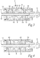
- is a cross section view according to III-III in
fig. 2 of a tool body according tofig. 1 , and - Fig. 4
- is a view similar to that of
fig. 3 of a tool body according to a second embodiment of the invention. -
Fig. 1 illustrates a machining tool 1 for turning having besides atool body 2 according to an embodiment of the invention amember 3 with acutting insert 4 for chip-removing machining in the form of turning secured at anend 5 of the tool body. The tool body may just as well be used in a machining tool for other types of machining, such as milling, drilling, or boring, and a corresponding member with at least one cutting edge for chip-removing machining is then to be secured to theend 5 of the tool body. - The tool body includes a
damping apparatus 6 for damping vibrations in the machining tool caused by machining operation, and this damping apparatus is arranged in an internal room 7 (seefig. 3 ) of the tool body defined by acasing 8. The damping apparatus comprises adamper mass body 9 with a circular cylindrical shape of a high density material, such as of lead, with an axial throughbore 10. Theinternal room 7 contains a damping fluid, such as oil, in anannular cavity 22 separating thedamper mass body 9 radially from internal walls of thecasing 8 defining the internal room. Acentral tube 11 extends through thethrough bore 10 and is rigidly secured to thedamper mass body 9 inside the through bore. Thecentral tube 11 is at bothends part member 3 with at least one cutting edge to be secured to the tool body, in this case end pieces. Thecentral tube 11 is made of a material with a spring property, such as steel or carbon fibre with this property, allowing thedamper mass body 9 to oscillate in theinternal room 7 of the tool body perpendicularly to the longitudinal extension of thecentral tube 11. The damping frequency of the damping apparatus will be proportional to the square root of k/m, in which k is the spring constant of the spring formed by the central tube with a spring property and m is the mass of thedamper mass body 9. The spring constant will depend upon the diameter and the wall thickness of the central tube as well as the material chosen for that tube, so that said frequency may be selected to match the frequency of the vibrations to be damped by appropriately choosing these characteristics of the central tube. Embodiments of the invention will by this without any problem allow to obtain such a frequency in the range of 300 Hz to 1 100 Hz, and frequencies outside this range are also conceivable. - The through bore 10 of the damper
mass body 9 has at each end thereof alength portion space mass boy 9 and thecentral tube 11. The choice of length of these length portions will also influence the spring constant of thecentral tube 11. -
Fig. 4 is a view similar tofig. 3 of a tool body according to a second embodiment of the invention differing from that shown infig. 3 by an arrangement of anelement respective space mass body 9 and thecentral tube 11. Theseelements central tube 11 with respect to the damper mass body and will influence the spring property of thecentral tube 11. Theelements central tube 11. The properties chosen for theseelements central tube 11. Furthermore, theelements - The invention is of course not restricted to the embodiments thereof described above, but many possibilities to modifications thereof would be apparent to a person with skill in the art without departing from the scope of the invention as defines in the appended claims.
- The length portions with larger cross-sections dimensions of the through bore of the damper mass body may have other lengths than shown in the figures or not be there at all. It is of course also possible to have the elements bridging the space between the central tube and the damper mass body immovably arranged or only one of them movable or having only one such element.
Claims (13)
- A tool body (2) including a damping apparatus for damping vibrations in a machining tool (1) having besides the tool body a member (3) with at least one cutting edge to be secured to the tool body, wherein the damping apparatus (6) is arranged in an internal room (7) of the tool body and comprises• a damper mass body (9)) with an axial through bore (10), and• a central tube (11) extending through said bore and which is rigidly secured to the damper mass body (9) inside the through bore (10),characterized in that the central tube (11) is at both ends (12, 13) thereof rigidly connected to a tool body fixed part (14, 15) and the central tube is made of a material with a spring property allowing the damper mass body (9) to oscillate in the internal room (7) perpendicularly to the longitudinal extension of the central tube (11).
- A tool body according to claim 1, characterized in that the central tube (11) is made of steel or carbon fibre.
- A tool body according to claim 1 or 2, characterized in that the through bore (10) has at at least one end thereof a length portion (16, 17) with larger cross-section dimensions than the central tube (11) leaving a space (18, 19) between the damper mass body (9) and the central tube (11), and that an element (21, 21) is arranged to bridge this space between the central tube and the damper mass body at a location along the central tube.
- A tool body according to claim 3, characterized in that said element (20, 21) is rigid.
- A tool body according to claim 3, characterized in that said element (20, 21) has elastic properties.
- A tool body according to claim 5, characterized in that said element (20, 21) is an O-ring of rubber.
- A tool body according to any of claims 3-6, characterized in that said element (20, 21) is movable along the central tube (11) between different said locations so as to change the spring constant of the central tube.
- A tool body according to any of claims 3-7, characterized in that the through bore (10) has a said length portion (16, 17) and a said element (20, 21) at both ends of the through bore.
- A tool body according to any of the preceding claims, characterized in that the central tube (11) is a machining tool cooling tube.
- A tool body according to any of the preceding claims, characterized in that the damper mass body (9) has a circular cylindrical shape with the through bore (10) extending according to the centre axis of the cylinder so formed.
- A tool body according to any of the preceding claims, characterized in that the internal room (7) contains a damping fluid, such as oil, in an annular cavity (22) separating the damper mass body (9) radially from internal walls defining the internal room (7).
- A machining tool, characterized in that it has a tool body (2) according to any of the preceding claims.
- Use of a tool body according to any of claims 1-11 to damp vibrations in a machining tool in operation.
Priority Applications (7)
| Application Number | Priority Date | Filing Date | Title |
|---|---|---|---|
| EP17194418.4A EP3461585B1 (en) | 2017-10-02 | 2017-10-02 | A tool body including a damping apparatus and a machining tool having such a tool body |
| JP2020539134A JP7212048B2 (en) | 2017-10-02 | 2018-09-11 | Tool body including damping device and machining tool with such tool body |
| US16/652,844 US11524340B2 (en) | 2017-10-02 | 2018-09-11 | Tool body including a damping apparatus and a machining tool having such a tool body |
| CA3073789A CA3073789A1 (en) | 2017-10-02 | 2018-09-11 | A tool body including a damping apparatus and a machining tool having such a tool body |
| CN201880059123.9A CN111194252B (en) | 2017-10-02 | 2018-09-11 | Tool body comprising a damping device and machining tool having such a tool body |
| PCT/EP2018/074471 WO2019068433A1 (en) | 2017-10-02 | 2018-09-11 | A tool body including a damping apparatus and a machining tool having such a tool body |
| IL272677A IL272677A (en) | 2017-10-02 | 2020-02-13 | Tool body including a damping apparatus and a machining tool having such a tool body |
Applications Claiming Priority (1)
| Application Number | Priority Date | Filing Date | Title |
|---|---|---|---|
| EP17194418.4A EP3461585B1 (en) | 2017-10-02 | 2017-10-02 | A tool body including a damping apparatus and a machining tool having such a tool body |
Publications (2)
| Publication Number | Publication Date |
|---|---|
| EP3461585A1 true EP3461585A1 (en) | 2019-04-03 |
| EP3461585B1 EP3461585B1 (en) | 2022-03-23 |
Family
ID=60037388
Family Applications (1)
| Application Number | Title | Priority Date | Filing Date |
|---|---|---|---|
| EP17194418.4A Active EP3461585B1 (en) | 2017-10-02 | 2017-10-02 | A tool body including a damping apparatus and a machining tool having such a tool body |
Country Status (7)
| Country | Link |
|---|---|
| US (1) | US11524340B2 (en) |
| EP (1) | EP3461585B1 (en) |
| JP (1) | JP7212048B2 (en) |
| CN (1) | CN111194252B (en) |
| CA (1) | CA3073789A1 (en) |
| IL (1) | IL272677A (en) |
| WO (1) | WO2019068433A1 (en) |
Cited By (2)
| Publication number | Priority date | Publication date | Assignee | Title |
|---|---|---|---|---|
| EP4029636A1 (en) * | 2021-01-19 | 2022-07-20 | KOMET Deutschland GmbH | Tool base and chip removing tool |
| EP4155023A1 (en) * | 2021-09-24 | 2023-03-29 | Franz Haimer Maschinenbau KG | Holder for a rotating tool |
Citations (4)
| Publication number | Priority date | Publication date | Assignee | Title |
|---|---|---|---|---|
| US3690414A (en) * | 1970-11-04 | 1972-09-12 | Cincinnati Milacron Inc | Vibration absorber for a supported member |
| WO1992014947A1 (en) | 1991-02-21 | 1992-09-03 | Teeness As | A means for damping vibrations, for example self-generated oscillations in boring bars and similar |
| EP2890915A1 (en) * | 2012-08-31 | 2015-07-08 | Sandvik Intellectual Property AB | Vibration-damped tool |
| US20160311031A1 (en) * | 2015-04-23 | 2016-10-27 | Enrico R. Giannetti | Through coolant machine tool having anti-vibration system |
Family Cites Families (21)
| Publication number | Priority date | Publication date | Assignee | Title |
|---|---|---|---|---|
| JPS5781006U (en) * | 1980-11-05 | 1982-05-19 | ||
| US4553884A (en) * | 1982-05-10 | 1985-11-19 | Kennametal Inc. | Boring tool and method of reducing vibrations therein |
| JPH0631507A (en) | 1992-07-16 | 1994-02-08 | Mitsubishi Materials Corp | Turning tool |
| SE513150C2 (en) * | 1998-12-17 | 2000-07-17 | Dentatus Ab | Motor-driven hand tool, for filing or grinding, with synchronously rotating imbalance bodies. |
| JP3714267B2 (en) | 2001-06-13 | 2005-11-09 | 三菱マテリアル株式会社 | Vibration control tool |
| US7028997B2 (en) * | 2001-06-13 | 2006-04-18 | Mitsubishi Materials Corporation | Vibration damping tool |
| NO321556B1 (en) | 2002-04-30 | 2006-05-29 | Teeness As | Damping device for damping vibrations |
| DE20215709U1 (en) | 2002-10-12 | 2004-02-26 | Ott-Jakob Gmbh & Co Spanntechnik Kg | tool clamping |
| JP2005036852A (en) | 2003-07-18 | 2005-02-10 | Tokai Rubber Ind Ltd | Vibration control device for rod member |
| DE102005025000A1 (en) * | 2005-06-01 | 2006-12-07 | Kennametal Inc. | Tool with fine adjustment |
| DE102005043626A1 (en) | 2005-09-13 | 2007-03-22 | Franz Haimer Maschinenbau Kg | Low-vibration tool holder |
| CN201115881Y (en) | 2007-10-26 | 2008-09-17 | 比亚迪股份有限公司 | Cutter for drill lathe |
| CN201128003Y (en) | 2007-12-26 | 2008-10-08 | 广西玉柴机器股份有限公司 | Following lathe cutter |
| FR2928344B1 (en) | 2008-03-06 | 2011-01-21 | Hutchinson | DAMPING DEVICE AND AERODYNE ROTOR SYSTEM INCORPORATING IT |
| FR2929868B1 (en) | 2008-04-10 | 2010-06-11 | E P B | TOOL HOLDER PROVIDED WITH A DAMAGE MEANS |
| JP5613958B2 (en) * | 2010-09-10 | 2014-10-29 | 大昭和精機株式会社 | Vibration control mechanism |
| FR3014516B1 (en) | 2013-12-05 | 2016-10-28 | Seco E P B | DAMPING MEMBER ADAPTED TO GENERATE A PHASE SHIFT AND / OR DISPLACEMENT AMPLITUDE BETWEEN THE PARTS OF ITS ABSORBING MASS |
| US9533357B2 (en) * | 2014-06-30 | 2017-01-03 | Kennametal Inc | Optimized vibration absorber |
| US20160067787A1 (en) * | 2014-09-09 | 2016-03-10 | Enrico R. Giannetti | Machine tool having anti-vibration tuning mechanism for chatter minimized machining |
| CN206190792U (en) | 2016-11-17 | 2017-05-24 | 长江大学 | Furthermore, |
| US20180281074A1 (en) * | 2017-03-31 | 2018-10-04 | Kennametal Inc. | Cantilever-supported tuned dynamic absorber |
-
2017
- 2017-10-02 EP EP17194418.4A patent/EP3461585B1/en active Active
-
2018
- 2018-09-11 JP JP2020539134A patent/JP7212048B2/en active Active
- 2018-09-11 CN CN201880059123.9A patent/CN111194252B/en active Active
- 2018-09-11 CA CA3073789A patent/CA3073789A1/en active Pending
- 2018-09-11 US US16/652,844 patent/US11524340B2/en active Active
- 2018-09-11 WO PCT/EP2018/074471 patent/WO2019068433A1/en active Application Filing
-
2020
- 2020-02-13 IL IL272677A patent/IL272677A/en unknown
Patent Citations (4)
| Publication number | Priority date | Publication date | Assignee | Title |
|---|---|---|---|---|
| US3690414A (en) * | 1970-11-04 | 1972-09-12 | Cincinnati Milacron Inc | Vibration absorber for a supported member |
| WO1992014947A1 (en) | 1991-02-21 | 1992-09-03 | Teeness As | A means for damping vibrations, for example self-generated oscillations in boring bars and similar |
| EP2890915A1 (en) * | 2012-08-31 | 2015-07-08 | Sandvik Intellectual Property AB | Vibration-damped tool |
| US20160311031A1 (en) * | 2015-04-23 | 2016-10-27 | Enrico R. Giannetti | Through coolant machine tool having anti-vibration system |
Cited By (3)
| Publication number | Priority date | Publication date | Assignee | Title |
|---|---|---|---|---|
| EP4029636A1 (en) * | 2021-01-19 | 2022-07-20 | KOMET Deutschland GmbH | Tool base and chip removing tool |
| WO2022156954A1 (en) * | 2021-01-19 | 2022-07-28 | Komet Deutschland Gmbh | Tool main part and cutting tool |
| EP4155023A1 (en) * | 2021-09-24 | 2023-03-29 | Franz Haimer Maschinenbau KG | Holder for a rotating tool |
Also Published As
| Publication number | Publication date |
|---|---|
| EP3461585B1 (en) | 2022-03-23 |
| JP2020535981A (en) | 2020-12-10 |
| IL272677A (en) | 2020-03-31 |
| US11524340B2 (en) | 2022-12-13 |
| WO2019068433A1 (en) | 2019-04-11 |
| CA3073789A1 (en) | 2019-04-11 |
| JP7212048B2 (en) | 2023-01-24 |
| CN111194252B (en) | 2021-12-03 |
| US20200246879A1 (en) | 2020-08-06 |
| CN111194252A (en) | 2020-05-22 |
Similar Documents
| Publication | Publication Date | Title |
|---|---|---|
| US7661912B2 (en) | Tool having damper | |
| US11524340B2 (en) | Tool body including a damping apparatus and a machining tool having such a tool body | |
| CN100522426C (en) | Damping apparatus for the damping of vibrations | |
| US20180281074A1 (en) | Cantilever-supported tuned dynamic absorber | |
| US20140283368A1 (en) | Adaptive design of fixture for thin-walled shell/cylindrical components | |
| US9533357B2 (en) | Optimized vibration absorber | |
| US3938626A (en) | Vibration damping assembly | |
| CN101554666A (en) | Tool holder equipped with a damping means | |
| KR20160094960A (en) | A movable element and a damping system | |
| CN109249043B (en) | Vibration-damping turning tool and design method thereof | |
| KR102349197B1 (en) | Damping device and tool-holding device with such damping device | |
| CN104640655B (en) | The vibration-proof structure of cutting element | |
| JP2008307642A (en) | Vibration isolating tool and its manufacturing method | |
| US20090274400A1 (en) | Rotating -Body Support Structure | |
| EP4366899A1 (en) | Tool holder damper | |
| CN208945190U (en) | A kind of hollow Boring Bar | |
| US9126267B2 (en) | Rod-shaped tool holder for attaching cutting bits at nodes | |
| Onozuka et al. | Optimal Design of a Damped Arbor for Heavy-Duty Machining of Giant Parts | |
| CN219616717U (en) | Damping device and vibration reduction cutter | |
| RU169720U1 (en) | BORING HEAD | |
| RU175939U1 (en) | DRILLING CORD | |
| CN114007810A (en) | Hand-held power tool |
Legal Events
| Date | Code | Title | Description |
|---|---|---|---|
| PUAI | Public reference made under article 153(3) epc to a published international application that has entered the european phase |
Free format text: ORIGINAL CODE: 0009012 |
|
| STAA | Information on the status of an ep patent application or granted ep patent |
Free format text: STATUS: THE APPLICATION HAS BEEN PUBLISHED |
|
| AK | Designated contracting states |
Kind code of ref document: A1 Designated state(s): AL AT BE BG CH CY CZ DE DK EE ES FI FR GB GR HR HU IE IS IT LI LT LU LV MC MK MT NL NO PL PT RO RS SE SI SK SM TR |
|
| AX | Request for extension of the european patent |
Extension state: BA ME |
|
| STAA | Information on the status of an ep patent application or granted ep patent |
Free format text: STATUS: REQUEST FOR EXAMINATION WAS MADE |
|
| 17P | Request for examination filed |
Effective date: 20191004 |
|
| RBV | Designated contracting states (corrected) |
Designated state(s): AL AT BE BG CH CY CZ DE DK EE ES FI FR GB GR HR HU IE IS IT LI LT LU LV MC MK MT NL NO PL PT RO RS SE SI SK SM TR |
|
| GRAP | Despatch of communication of intention to grant a patent |
Free format text: ORIGINAL CODE: EPIDOSNIGR1 |
|
| STAA | Information on the status of an ep patent application or granted ep patent |
Free format text: STATUS: GRANT OF PATENT IS INTENDED |
|
| INTG | Intention to grant announced |
Effective date: 20211021 |
|
| GRAS | Grant fee paid |
Free format text: ORIGINAL CODE: EPIDOSNIGR3 |
|
| GRAA | (expected) grant |
Free format text: ORIGINAL CODE: 0009210 |
|
| STAA | Information on the status of an ep patent application or granted ep patent |
Free format text: STATUS: THE PATENT HAS BEEN GRANTED |
|
| AK | Designated contracting states |
Kind code of ref document: B1 Designated state(s): AL AT BE BG CH CY CZ DE DK EE ES FI FR GB GR HR HU IE IS IT LI LT LU LV MC MK MT NL NO PL PT RO RS SE SI SK SM TR |
|
| REG | Reference to a national code |
Ref country code: GB Ref legal event code: FG4D |
|
| REG | Reference to a national code |
Ref country code: CH Ref legal event code: EP |
|
| REG | Reference to a national code |
Ref country code: IE Ref legal event code: FG4D |
|
| REG | Reference to a national code |
Ref country code: DE Ref legal event code: R096 Ref document number: 602017054856 Country of ref document: DE |
|
| REG | Reference to a national code |
Ref country code: AT Ref legal event code: REF Ref document number: 1477118 Country of ref document: AT Kind code of ref document: T Effective date: 20220415 |
|
| REG | Reference to a national code |
Ref country code: LT Ref legal event code: MG9D |
|
| REG | Reference to a national code |
Ref country code: NL Ref legal event code: MP Effective date: 20220323 |
|
| PG25 | Lapsed in a contracting state [announced via postgrant information from national office to epo] |
Ref country code: SE Free format text: LAPSE BECAUSE OF FAILURE TO SUBMIT A TRANSLATION OF THE DESCRIPTION OR TO PAY THE FEE WITHIN THE PRESCRIBED TIME-LIMIT Effective date: 20220323 Ref country code: RS Free format text: LAPSE BECAUSE OF FAILURE TO SUBMIT A TRANSLATION OF THE DESCRIPTION OR TO PAY THE FEE WITHIN THE PRESCRIBED TIME-LIMIT Effective date: 20220323 Ref country code: NO Free format text: LAPSE BECAUSE OF FAILURE TO SUBMIT A TRANSLATION OF THE DESCRIPTION OR TO PAY THE FEE WITHIN THE PRESCRIBED TIME-LIMIT Effective date: 20220623 Ref country code: LT Free format text: LAPSE BECAUSE OF FAILURE TO SUBMIT A TRANSLATION OF THE DESCRIPTION OR TO PAY THE FEE WITHIN THE PRESCRIBED TIME-LIMIT Effective date: 20220323 Ref country code: HR Free format text: LAPSE BECAUSE OF FAILURE TO SUBMIT A TRANSLATION OF THE DESCRIPTION OR TO PAY THE FEE WITHIN THE PRESCRIBED TIME-LIMIT Effective date: 20220323 Ref country code: BG Free format text: LAPSE BECAUSE OF FAILURE TO SUBMIT A TRANSLATION OF THE DESCRIPTION OR TO PAY THE FEE WITHIN THE PRESCRIBED TIME-LIMIT Effective date: 20220623 |
|
| REG | Reference to a national code |
Ref country code: AT Ref legal event code: MK05 Ref document number: 1477118 Country of ref document: AT Kind code of ref document: T Effective date: 20220323 |
|
| PG25 | Lapsed in a contracting state [announced via postgrant information from national office to epo] |
Ref country code: LV Free format text: LAPSE BECAUSE OF FAILURE TO SUBMIT A TRANSLATION OF THE DESCRIPTION OR TO PAY THE FEE WITHIN THE PRESCRIBED TIME-LIMIT Effective date: 20220323 Ref country code: GR Free format text: LAPSE BECAUSE OF FAILURE TO SUBMIT A TRANSLATION OF THE DESCRIPTION OR TO PAY THE FEE WITHIN THE PRESCRIBED TIME-LIMIT Effective date: 20220624 Ref country code: FI Free format text: LAPSE BECAUSE OF FAILURE TO SUBMIT A TRANSLATION OF THE DESCRIPTION OR TO PAY THE FEE WITHIN THE PRESCRIBED TIME-LIMIT Effective date: 20220323 |
|
| PG25 | Lapsed in a contracting state [announced via postgrant information from national office to epo] |
Ref country code: NL Free format text: LAPSE BECAUSE OF FAILURE TO SUBMIT A TRANSLATION OF THE DESCRIPTION OR TO PAY THE FEE WITHIN THE PRESCRIBED TIME-LIMIT Effective date: 20220323 |
|
| PG25 | Lapsed in a contracting state [announced via postgrant information from national office to epo] |
Ref country code: SM Free format text: LAPSE BECAUSE OF FAILURE TO SUBMIT A TRANSLATION OF THE DESCRIPTION OR TO PAY THE FEE WITHIN THE PRESCRIBED TIME-LIMIT Effective date: 20220323 Ref country code: SK Free format text: LAPSE BECAUSE OF FAILURE TO SUBMIT A TRANSLATION OF THE DESCRIPTION OR TO PAY THE FEE WITHIN THE PRESCRIBED TIME-LIMIT Effective date: 20220323 Ref country code: RO Free format text: LAPSE BECAUSE OF FAILURE TO SUBMIT A TRANSLATION OF THE DESCRIPTION OR TO PAY THE FEE WITHIN THE PRESCRIBED TIME-LIMIT Effective date: 20220323 Ref country code: PT Free format text: LAPSE BECAUSE OF FAILURE TO SUBMIT A TRANSLATION OF THE DESCRIPTION OR TO PAY THE FEE WITHIN THE PRESCRIBED TIME-LIMIT Effective date: 20220725 Ref country code: ES Free format text: LAPSE BECAUSE OF FAILURE TO SUBMIT A TRANSLATION OF THE DESCRIPTION OR TO PAY THE FEE WITHIN THE PRESCRIBED TIME-LIMIT Effective date: 20220323 Ref country code: EE Free format text: LAPSE BECAUSE OF FAILURE TO SUBMIT A TRANSLATION OF THE DESCRIPTION OR TO PAY THE FEE WITHIN THE PRESCRIBED TIME-LIMIT Effective date: 20220323 Ref country code: CZ Free format text: LAPSE BECAUSE OF FAILURE TO SUBMIT A TRANSLATION OF THE DESCRIPTION OR TO PAY THE FEE WITHIN THE PRESCRIBED TIME-LIMIT Effective date: 20220323 Ref country code: AT Free format text: LAPSE BECAUSE OF FAILURE TO SUBMIT A TRANSLATION OF THE DESCRIPTION OR TO PAY THE FEE WITHIN THE PRESCRIBED TIME-LIMIT Effective date: 20220323 |
|
| PG25 | Lapsed in a contracting state [announced via postgrant information from national office to epo] |
Ref country code: PL Free format text: LAPSE BECAUSE OF FAILURE TO SUBMIT A TRANSLATION OF THE DESCRIPTION OR TO PAY THE FEE WITHIN THE PRESCRIBED TIME-LIMIT Effective date: 20220323 Ref country code: IS Free format text: LAPSE BECAUSE OF FAILURE TO SUBMIT A TRANSLATION OF THE DESCRIPTION OR TO PAY THE FEE WITHIN THE PRESCRIBED TIME-LIMIT Effective date: 20220723 Ref country code: AL Free format text: LAPSE BECAUSE OF FAILURE TO SUBMIT A TRANSLATION OF THE DESCRIPTION OR TO PAY THE FEE WITHIN THE PRESCRIBED TIME-LIMIT Effective date: 20220323 |
|
| REG | Reference to a national code |
Ref country code: DE Ref legal event code: R097 Ref document number: 602017054856 Country of ref document: DE |
|
| PLBE | No opposition filed within time limit |
Free format text: ORIGINAL CODE: 0009261 |
|
| STAA | Information on the status of an ep patent application or granted ep patent |
Free format text: STATUS: NO OPPOSITION FILED WITHIN TIME LIMIT |
|
| PG25 | Lapsed in a contracting state [announced via postgrant information from national office to epo] |
Ref country code: DK Free format text: LAPSE BECAUSE OF FAILURE TO SUBMIT A TRANSLATION OF THE DESCRIPTION OR TO PAY THE FEE WITHIN THE PRESCRIBED TIME-LIMIT Effective date: 20220323 |
|
| 26N | No opposition filed |
Effective date: 20230102 |
|
| PG25 | Lapsed in a contracting state [announced via postgrant information from national office to epo] |
Ref country code: SI Free format text: LAPSE BECAUSE OF FAILURE TO SUBMIT A TRANSLATION OF THE DESCRIPTION OR TO PAY THE FEE WITHIN THE PRESCRIBED TIME-LIMIT Effective date: 20220323 Ref country code: MC Free format text: LAPSE BECAUSE OF FAILURE TO SUBMIT A TRANSLATION OF THE DESCRIPTION OR TO PAY THE FEE WITHIN THE PRESCRIBED TIME-LIMIT Effective date: 20220323 |
|
| REG | Reference to a national code |
Ref country code: CH Ref legal event code: PL |
|
| REG | Reference to a national code |
Ref country code: BE Ref legal event code: MM Effective date: 20221031 |
|
| PG25 | Lapsed in a contracting state [announced via postgrant information from national office to epo] |
Ref country code: LU Free format text: LAPSE BECAUSE OF NON-PAYMENT OF DUE FEES Effective date: 20221002 |
|
| PG25 | Lapsed in a contracting state [announced via postgrant information from national office to epo] |
Ref country code: LI Free format text: LAPSE BECAUSE OF NON-PAYMENT OF DUE FEES Effective date: 20221031 Ref country code: CH Free format text: LAPSE BECAUSE OF NON-PAYMENT OF DUE FEES Effective date: 20221031 |
|
| PG25 | Lapsed in a contracting state [announced via postgrant information from national office to epo] |
Ref country code: BE Free format text: LAPSE BECAUSE OF NON-PAYMENT OF DUE FEES Effective date: 20221031 |
|
| PG25 | Lapsed in a contracting state [announced via postgrant information from national office to epo] |
Ref country code: IE Free format text: LAPSE BECAUSE OF NON-PAYMENT OF DUE FEES Effective date: 20221002 |
|
| PGFP | Annual fee paid to national office [announced via postgrant information from national office to epo] |
Ref country code: IT Payment date: 20230913 Year of fee payment: 7 Ref country code: GB Payment date: 20230831 Year of fee payment: 7 |
|
| PGFP | Annual fee paid to national office [announced via postgrant information from national office to epo] |
Ref country code: FR Payment date: 20230921 Year of fee payment: 7 |
|
| PGFP | Annual fee paid to national office [announced via postgrant information from national office to epo] |
Ref country code: DE Payment date: 20230906 Year of fee payment: 7 |
|
| PG25 | Lapsed in a contracting state [announced via postgrant information from national office to epo] |
Ref country code: HU Free format text: LAPSE BECAUSE OF FAILURE TO SUBMIT A TRANSLATION OF THE DESCRIPTION OR TO PAY THE FEE WITHIN THE PRESCRIBED TIME-LIMIT; INVALID AB INITIO Effective date: 20171002 |
|
| PG25 | Lapsed in a contracting state [announced via postgrant information from national office to epo] |
Ref country code: CY Free format text: LAPSE BECAUSE OF FAILURE TO SUBMIT A TRANSLATION OF THE DESCRIPTION OR TO PAY THE FEE WITHIN THE PRESCRIBED TIME-LIMIT Effective date: 20220323 |