EP3461359A1 - Belt buckle for a vehicle safety belt - Google Patents
Belt buckle for a vehicle safety belt Download PDFInfo
- Publication number
- EP3461359A1 EP3461359A1 EP18195922.2A EP18195922A EP3461359A1 EP 3461359 A1 EP3461359 A1 EP 3461359A1 EP 18195922 A EP18195922 A EP 18195922A EP 3461359 A1 EP3461359 A1 EP 3461359A1
- Authority
- EP
- European Patent Office
- Prior art keywords
- housing
- belt
- belt buckle
- pushbutton
- luminous element
- Prior art date
- Legal status (The legal status is an assumption and is not a legal conclusion. Google has not performed a legal analysis and makes no representation as to the accuracy of the status listed.)
- Withdrawn
Links
Images



Classifications
-
- A—HUMAN NECESSITIES
- A44—HABERDASHERY; JEWELLERY
- A44B—BUTTONS, PINS, BUCKLES, SLIDE FASTENERS, OR THE LIKE
- A44B11/00—Buckles; Similar fasteners for interconnecting straps or the like, e.g. for safety belts
- A44B11/25—Buckles; Similar fasteners for interconnecting straps or the like, e.g. for safety belts with two or more separable parts
- A44B11/2503—Safety buckles
- A44B11/2546—Details
- A44B11/2565—Illuminated buckles
-
- A—HUMAN NECESSITIES
- A44—HABERDASHERY; JEWELLERY
- A44B—BUTTONS, PINS, BUCKLES, SLIDE FASTENERS, OR THE LIKE
- A44B11/00—Buckles; Similar fasteners for interconnecting straps or the like, e.g. for safety belts
- A44B11/001—Ornamental buckles
- A44B11/003—Ornamental buckles covered with cloth or other material; Making thereof
-
- A—HUMAN NECESSITIES
- A44—HABERDASHERY; JEWELLERY
- A44B—BUTTONS, PINS, BUCKLES, SLIDE FASTENERS, OR THE LIKE
- A44B11/00—Buckles; Similar fasteners for interconnecting straps or the like, e.g. for safety belts
- A44B11/25—Buckles; Similar fasteners for interconnecting straps or the like, e.g. for safety belts with two or more separable parts
- A44B11/2503—Safety buckles
- A44B11/2507—Safety buckles actuated by a push-button
- A44B11/2515—Safety buckles actuated by a push-button acting parallel to the main plane of the buckle and perpendicularly to the direction of the fastening action
-
- A—HUMAN NECESSITIES
- A44—HABERDASHERY; JEWELLERY
- A44B—BUTTONS, PINS, BUCKLES, SLIDE FASTENERS, OR THE LIKE
- A44B11/00—Buckles; Similar fasteners for interconnecting straps or the like, e.g. for safety belts
- A44B11/25—Buckles; Similar fasteners for interconnecting straps or the like, e.g. for safety belts with two or more separable parts
- A44B11/2503—Safety buckles
- A44B11/2507—Safety buckles actuated by a push-button
- A44B11/2523—Safety buckles actuated by a push-button acting parallel to the main plane of the buckle and in the same direction as the fastening action
-
- A—HUMAN NECESSITIES
- A44—HABERDASHERY; JEWELLERY
- A44B—BUTTONS, PINS, BUCKLES, SLIDE FASTENERS, OR THE LIKE
- A44B11/00—Buckles; Similar fasteners for interconnecting straps or the like, e.g. for safety belts
- A44B11/25—Buckles; Similar fasteners for interconnecting straps or the like, e.g. for safety belts with two or more separable parts
- A44B11/2503—Safety buckles
- A44B11/2546—Details
-
- B—PERFORMING OPERATIONS; TRANSPORTING
- B60—VEHICLES IN GENERAL
- B60Q—ARRANGEMENT OF SIGNALLING OR LIGHTING DEVICES, THE MOUNTING OR SUPPORTING THEREOF OR CIRCUITS THEREFOR, FOR VEHICLES IN GENERAL
- B60Q3/00—Arrangement of lighting devices for vehicle interiors; Lighting devices specially adapted for vehicle interiors
- B60Q3/20—Arrangement of lighting devices for vehicle interiors; Lighting devices specially adapted for vehicle interiors for lighting specific fittings of passenger or driving compartments; mounted on specific fittings of passenger or driving compartments
- B60Q3/233—Seats; Arm rests; Head rests
-
- B—PERFORMING OPERATIONS; TRANSPORTING
- B60—VEHICLES IN GENERAL
- B60Q—ARRANGEMENT OF SIGNALLING OR LIGHTING DEVICES, THE MOUNTING OR SUPPORTING THEREOF OR CIRCUITS THEREFOR, FOR VEHICLES IN GENERAL
- B60Q3/00—Arrangement of lighting devices for vehicle interiors; Lighting devices specially adapted for vehicle interiors
- B60Q3/20—Arrangement of lighting devices for vehicle interiors; Lighting devices specially adapted for vehicle interiors for lighting specific fittings of passenger or driving compartments; mounted on specific fittings of passenger or driving compartments
- B60Q3/242—Safety belts; Body harnesses
-
- B—PERFORMING OPERATIONS; TRANSPORTING
- B60—VEHICLES IN GENERAL
- B60Q—ARRANGEMENT OF SIGNALLING OR LIGHTING DEVICES, THE MOUNTING OR SUPPORTING THEREOF OR CIRCUITS THEREFOR, FOR VEHICLES IN GENERAL
- B60Q3/00—Arrangement of lighting devices for vehicle interiors; Lighting devices specially adapted for vehicle interiors
- B60Q3/60—Arrangement of lighting devices for vehicle interiors; Lighting devices specially adapted for vehicle interiors characterised by optical aspects
- B60Q3/62—Arrangement of lighting devices for vehicle interiors; Lighting devices specially adapted for vehicle interiors characterised by optical aspects using light guides
- B60Q3/64—Arrangement of lighting devices for vehicle interiors; Lighting devices specially adapted for vehicle interiors characterised by optical aspects using light guides for a single lighting device
-
- B—PERFORMING OPERATIONS; TRANSPORTING
- B60—VEHICLES IN GENERAL
- B60Q—ARRANGEMENT OF SIGNALLING OR LIGHTING DEVICES, THE MOUNTING OR SUPPORTING THEREOF OR CIRCUITS THEREFOR, FOR VEHICLES IN GENERAL
- B60Q3/00—Arrangement of lighting devices for vehicle interiors; Lighting devices specially adapted for vehicle interiors
- B60Q3/80—Circuits; Control arrangements
-
- B—PERFORMING OPERATIONS; TRANSPORTING
- B60—VEHICLES IN GENERAL
- B60Q—ARRANGEMENT OF SIGNALLING OR LIGHTING DEVICES, THE MOUNTING OR SUPPORTING THEREOF OR CIRCUITS THEREFOR, FOR VEHICLES IN GENERAL
- B60Q3/00—Arrangement of lighting devices for vehicle interiors; Lighting devices specially adapted for vehicle interiors
- B60Q3/80—Circuits; Control arrangements
- B60Q3/82—Switches specially adapted for vehicle interior lighting, e.g. switching by tilting the lens
-
- B—PERFORMING OPERATIONS; TRANSPORTING
- B60—VEHICLES IN GENERAL
- B60R—VEHICLES, VEHICLE FITTINGS, OR VEHICLE PARTS, NOT OTHERWISE PROVIDED FOR
- B60R22/00—Safety belts or body harnesses in vehicles
- B60R22/12—Construction of belts or harnesses
-
- F—MECHANICAL ENGINEERING; LIGHTING; HEATING; WEAPONS; BLASTING
- F21—LIGHTING
- F21V—FUNCTIONAL FEATURES OR DETAILS OF LIGHTING DEVICES OR SYSTEMS THEREOF; STRUCTURAL COMBINATIONS OF LIGHTING DEVICES WITH OTHER ARTICLES, NOT OTHERWISE PROVIDED FOR
- F21V23/00—Arrangement of electric circuit elements in or on lighting devices
- F21V23/04—Arrangement of electric circuit elements in or on lighting devices the elements being switches
- F21V23/0442—Arrangement of electric circuit elements in or on lighting devices the elements being switches activated by means of a sensor, e.g. motion or photodetectors
-
- F—MECHANICAL ENGINEERING; LIGHTING; HEATING; WEAPONS; BLASTING
- F21—LIGHTING
- F21V—FUNCTIONAL FEATURES OR DETAILS OF LIGHTING DEVICES OR SYSTEMS THEREOF; STRUCTURAL COMBINATIONS OF LIGHTING DEVICES WITH OTHER ARTICLES, NOT OTHERWISE PROVIDED FOR
- F21V33/00—Structural combinations of lighting devices with other articles, not otherwise provided for
- F21V33/0064—Health, life-saving or fire-fighting equipment
-
- F—MECHANICAL ENGINEERING; LIGHTING; HEATING; WEAPONS; BLASTING
- F21—LIGHTING
- F21W—INDEXING SCHEME ASSOCIATED WITH SUBCLASSES F21K, F21L, F21S and F21V, RELATING TO USES OR APPLICATIONS OF LIGHTING DEVICES OR SYSTEMS
- F21W2106/00—Interior vehicle lighting devices
Definitions
- the invention relates to a belt buckle for a vehicle safety belt, comprising a housing in which a locking mechanism is arranged, and a pushbutton, provided on said housing, for operating the locking mechanism.
- the object of the invention is to provide a belt buckle of the kind initially specified, in which the two housing shells can be joined securely together in a simple manner to form the housing.
- the at least two housing shells from which the housing is formed are joined at their shell rims.
- Elongated cover strips made of solid material and covering the mutually abutting rims of the housing shells are fixed to the joined housing shells.
- the cover strips may preferably be adapted to secure the housing shells to each other against a disconnecting movement.
- the at least two housing shells may be joined to each other by welding them together at their rims.
- the resultant weld seams are covered by the cover strips.
- the at least two housing shells may preferably have engaging members at their shell rims, which by means of a particular movement can be brought into engagement with each other. By this means, the at least two housing shells are joined together.
- the elongated cover strips are moulded integrally onto one of the two housing shells.
- the engaging members are preferably embodied in such a way that they overlap in their engaged position, and that the housing shells are joined to each other by a movement substantially parallel to the rims of the housing shell.
- the engaging members may have stop faces which prevent a sliding movement transverse to the movement with which the housing shells are joined to each other.
- Securing members which are in engagement with corresponding securing members formed on the joined housing shells may be provided on the inner surfaces of the cover strips, facing the joined housing shells. This causes the joined housing shells to be secured to each other against a disconnecting movement.
- the cover strips may also be embodied as clamp members, the clamping engagement of which on the joined housing shells preventing any disconnecting movement of the housing shells. This securing against the housing shells coming apart can also be achieved by the cover strips not only being embodied as clamp members, but also having the securing members which engage with the securing members formed on the housing shells.
- cover strips and the ring are preferably of one-piece construction.
- the cover strips and the ring may of metal or plastic.
- Another advantageous embodiment of the invention is when the housing shells forming the housing each have a surface covering, the abutting edges of which, when the housing shells are joined together, are covered by the cover strips.
- the surface covering may be made of a different material from that of the housing shells, in particular of a decorative material. Suitable decorative materials include, for example, leather, textile fabric, films, carbon fibre fabric, plastic, metal and the like.
- the surface covering may be embodied in the form of an overlay.
- the surface covering is preferably embodied as a shaped body, in particular as a cover shell.
- the shape of the shaped body or cover shell is adapted to the outer surface of the housing shells.
- the surface covering preferably consists of a sound-absorbing material. Sound-absorbing embossments may be additionally provided on the outer side of the surface covering. However, it is also possible to achieve sound absorption by the embossments on the surface covering.
- the pushbutton of the belt buckle may likewise have a surface covering, in particular of a decorative material.
- the pushbutton portion which is located in the insertion opening for a belt tongue joined to the safety belt or which is adjacent to said insertion opening may have a harder surface than the rest of the surface covering disposed on the pushbutton. Operation of the pushbutton can be improved and made more pleasant by means of the surface covering on the pushbutton, said surface covering consisting in particular of a decorative material, and in particular in the pushbutton portion to which pressure can be manually applied.
- the harder surface in the region of the insertion opening can also be achieved by post-curing the material of the surface covering.
- This post-curing can be achieved with a coating which hardens, for example a plastic coating, or by applying a coat of paint or varnish to the surface, or by impregnating the surface.
- the invention also relates to a belt buckle for a vehicle safety belt, in which a locking mechanism is provided in the housing, with which a belt tongue which is inserted through an insertion opening and which is joined to the safety belt can be releasably locked.
- a visual display device is also provided on the housing, which can be perceived outside the housing with the aid of at least one luminous element disposed inside the housing.
- Belt buckles in which the lock state of the belt buckle is indicated by the visual display device are known from DE 2003 15 9 58 U1 and DE 10 2010 0 26 913 A1 , for example.
- the invention differs from the latter by the at least one luminous element being embodied in such a way that the interior portion of the housing immediately adjacent to the pushbutton is illuminated, and in that a translucent gap is formed between the opaque pushbutton and an opaque rim of the housing recess in which the pushbutton is disposed.
- the housing components adjacent to the illuminated interior portion, and the pushbutton itself, are impermeable to light, so the light can escape from the inside of the housing through the gap only. This ensures that the position of the pushbutton is clearly indicated so as to make it easier to operate, even when visibility is poor, and specifically when it is dark inside the passenger compartment.
- the translucent gap is advantageously designed in such a way that it is provided at least at the pushbutton edges on the opaque portion of the pushbutton to which pressure can be manually applied.
- the geometrical dimensions of the opaque portion of the pushbutton to which pressure can be manually applied and which is used to operate the belt buckle are rendered discernible by this means.
- the illuminated gap may have be U-shaped, for example, and may form a continuous or a broken illuminated line.
- the gap may also have a translucent cover at the pushbutton and/or at the edge of the housing recess.
- the at least one luminous element may also be configured in such a way that the insertion opening is also illuminated when the belt tongue has been removed.
- the at least one luminous element is preferably integrated in a sensor device which detects the lock state of the belt buckle, for example to detect whether the associated motor vehicle seat is occupied or not.
- the luminous element may be installed in the casing of the sensor device for detecting the lock state, or in the switch or the display device in a way that ensures the housing interior is illuminated in the manner described above.
- the at least one luminous element is preferably switched on by opening at least one of the vehicle doors and before the vehicle engine is started.
- the at least one luminous element it is also possible for the at least one luminous element to be switched on by a switching function that is performed between the latter two actions.
- the at least one luminous element preferably remains switched on during the period in which the belt tongue is locked in place in the locking mechanism. This ensures that the geometrical outlines shape of the pushbutton portion to which pressure can be manually applied are clearly indicated for the purpose of releasing the belt tongue from the locking mechanism, so that they are also discernible even when visibility inside the passenger compartment is poor.
- fibre-optic light guides may lead from the at least one luminous element to the gap to be illuminated and/or to the insertion opening to be illuminated, for example with the aid of a fibre optic coupler. It is also possible to provide at least two luminous elements which are assigned respectively to illuminate the insertion opening and to illuminate the gap.
- An LED is preferably suitable for the at least one luminous element.
- a belt buckle for a vehicle safety belt as shown in the Figures, include a housing 3 in which a locking mechanism 4 ( Figure 12 ) is arranged.
- a pushbutton 22 provided on housing 3 is used to operate locking mechanism 4.
- locking mechanism 4 By means of locking mechanism 4, it is possible to lock in place a belt tongue 26 which is connected to a safety belt 25 and which can be inserted into an insertion opening 24.
- the belt tongue is locked automatically into place when it is inserted into locking mechanism 4.
- pressure is applied externally and manually to pushbutton 22. After being released from the locked state, belt tongue 26 is then ejected from the locking mechanism.
- housing 3 may be formed by two housing shells 1 and 2. At their shell rims 5, housing shells 1 and 2 have engaging members 6 and 7 which can be brought into engagement with each other by sliding them against each other when rims 17, 18 of the housing shells abut each other. In the embodiments shown, this sliding movement is performed parallel to abutting rims 17 and 18.
- Engaging members 6 and 7 may be embodied in such a way that they overlap in their engaged position, as shown in Figure 6 .
- the mutually engaging members 6, 7 may have stop faces 10, 11 abutting each other, which prevent a sliding movement transverse to the connecting movement.
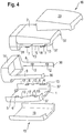
- engaging members 6 and 7 may extend substantially along the entire abutting rims of housing shells 1 and 2. However, it is also possible that engaging members 6 and 7 extend only partly along the length of abutting rims 17 and 18 of housing shells 1 and 2, as shown in Figure 4 .
- the two housing shells 1 and 2 are joined to each other by engagement of engaging members 6 and 7, preferably in an overlapping arrangement as shown in Figure 6 .
- elongated cover strips 8 and 9 made of solid material are provided which cover the mutually abutting rims 17 and 18 of housing shells 1 and 2.
- These elongated cover strips 8 and 9 may have securing members 12 disposed on their respective inner surfaces facing the joined housing shells 1 and 2, which engage in corresponding securing members 13 formed on the joined housing shells 1 and 2.
- inwardly extending projections forming securing members 12 are provided on cover strips 8 and 9.
- Corresponding recesses are provided in the region of rims 17 and 18 on the abutting housing shells 1 and 2 and form the corresponding securing members 13 into which the projections provided on the cover strips extend. This ensures that when housing shells 1 and 2 are in the assembled state, they can no longer move relative to each other, so a secure join is produced to form housing 3.
- cover strips 8 and 9 as clamp members. Their free ends may be embodied as clamp ends 36, as shown in Figure 11 , which prevent any disconnecting movement of the joined housing shells 1 and 2.
- clamp ends 36 of cover strips 8 and 9 are placed around the joined housing shells 1 and 2, as illustrated in Figure 11 .
- the joined housing shells 1 and 2 are gripped in the region where their rims abut, in particular in the region of their inwardly facing rim portions 37, as shown in Figure 4 .
- engaging members 6 and 7 extend substantially along the entire abutting rims.
- Ring 14 and cover strips 8 and 9 are preferably of one-piece construction. Cover strips 8 and 9 may be provided on ring 14 so that clamp ends 36 come into springy engagement with the inwardly facing rim portions 37 of housing shells 1 and 2. The other ends of cover strips 8 and 9 are preferably joined integrally to ring 14. Ring 14 and cover strips 8 and 9 are preferably of metal. However, they may also consist of a suitable plastic, for example a fibre-reinforced plastic. Attachment to the joined housing shells 1 and 2 is achieved by ring 14 being pushed with a close fit over the housing portion adjacent to pushbutton 22, as can be seen from Figure 1 .
- FIG. 7 shows in cross-section how the rims 43 and 44 of housing shells 1 and 2 in Figure 5 are slid over each other.
- the two housing shells 1 and 2 may have a surface covering (15, 16).
- These surface coverings 15, 16 are preferably in the form of shaped bodies, in particular in the form of cover shells 19, 20, as shown in Figure 4 .
- surface coverings 15, 16 may also be embodied in the form of coating, an overlay, or the like.
- Surface coverings 15 and 16 consist of a different material from that of the housing shells, in particular of a decorative material. Suitable decorative materials include, for example, natural leather, imitation leather, textile fabrics, or fabrics made of plastic fibres, carbon fibres, metal fibres and the like.
- Surface coverings 15 and 16 consisting of a sound-absorbing material are preferably used. Suitable such materials include leather, imitation leather, textile fabrics and other fabrics. Sound-absorbing embossments (not shown in further detail) may preferably be provided on the outer side of surface coverings 15, 16. With these embossments, the outer sides of surface coverings 15, 16 lie against vehicle components such as seat components or the centre console.
- ring 14 covers the upper rim of the shorter housing shell (bottom housing shell) 1 and the upper rim of surface coverings 15 and 16. Ring 14 also surrounds the ring-shaped upper portion of upper housing shell 2 in which a recess is formed. Pushbutton 22 is disposed in the latter recess.
- the two housing shells 1 and 2 are joined fixedly to each other by that means also.
- Pushbutton 22 may also have a surface covering 38.
- This surface covering may likewise consist of a decorative material.
- This decorative material may be the same as the material of surface coverings 15 and 16 for housing shells 1 and 2. However, it may also be a material different from the latter. Examples of materials used for surface covering 38 include leather, imitation leather, or a plastic material that feels on the surface like leather. If substantially the entire surface of pushbutton 22 is fitted with surface covering 38, it is advantageous to provide a pushbutton portion 23 which is adjacent to insertion opening 24 and also, more particularly, to provide a slanting pushbutton portion 42 opposite the remaining pushbutton portion with a hardened surface. That portion of surface covering 38 may be treated by post-curing to achieve that purpose.
- a hardening overlay of plastic, for example, or a coating of paint or varnish, or a hardening impregnation of the material of surface covering 38 are suitable in this regard.
- Figure 12 shows an embodiment of a belt buckle, in which an illumination device in the form of at least one luminous element 27 is provided inside the housing.
- the illumination device 29 inside the housing, in particular the at least one luminous element 27, is adapted to illuminate at least one interior portion 32 immediately adjacent to pushbutton 22 (the underside of the pushbutton) inside housing 3.
- a translucent gap 30 is formed between the opaque pushbutton 22 and the opaque rim 31 surrounding the housing recess in which pushbutton 22 is disposed.
- the ring-shaped rim portion 31 is integrally joined to housing shell 2, which together with the other housing shell 1 encloses the inside of the housing.
- the ring-shaped rim portion 31 surrounds pushbutton 22 and consists, like the entire housing 3, of opaque material.
- the light emitted from the inside of the housing escapes to the outside through the gap 30 formed between pushbutton 22 and the ring-shaped rim portion 31.
- the surface of the pushbutton and in particular its lateral borders are made visually discernible, thus allowing the position of the pushbutton in the vehicle to be seen even when visibility inside the vehicle is poor.
- the translucent gap 30 is present at the pushbutton edges forming a pushbutton portion 34 to which pressure is manually applied ( Figure 2 ).
- Illumination device 29, in particular the at least one luminous element 27, may also be adapted and arranged in such a way that the insertion opening 24 is likewise illuminated when the belt tongue 26 has been removed from the belt buckle.
- a perimeter region 35 of insertion opening 24 may be illuminated by a fibre optic (not shown), for example.
- the at least one luminous element 27 is preferably integrated in a sensor device 28 or switch for detecting the lock state of locking mechanism 4.
- Luminous element 27 is disposed, more particularly, in the housing of said sensor device 28.
- a sensor device is known from Such an airbag arrangement is known from US 5,960,523 , for example.
- the at least one luminous element 27 is preferably switched on by a switch 41 ( Figure 13 ) being closed when at least one of the vehicle doors is opened and before the vehicle engine is started.
- the at least one luminous element 27 may also be switched on by a switching function that is performed between the latter two actions.
- the at least one luminous element also remains switched on when belt tongue 26 is locked in place in locking mechanism 4. In this way, the position of pushbutton 22 and in particular the opaque portion of the pushbutton portion 34 to which pressure is manually applied in order to operate the pushbutton is made visually discernible.
- Figure 13 shows a circuit for supplying power to the luminous element 27 embodied as an LED.
- Luminous element 27 is supplied with power from a power supply source 39 via a series resistor 40 when switch 41 is closed.
- switch 41 is closed when at least one vehicle door is opened, but it can also be closed by some other switching function between the door being opened and the engine of the vehicle being started.
- the power is supplied via a cable 45 ( Figure 12 ).
- Figure 14 shows, in a plan view onto the belt buckle, the states in which belt tongue 26 has been removed from the belt buckle ( Figure 14A ) and in which belt tongue 26 has been inserted into insertion slot 24 and locked into locking mechanism 4 ( Figure 14B ).
- the illumination for indicating insertion slot 24 and gap 30 is switched between these two states.
- a perimeter region 46 which may be triangular in shape with a point pointing towards insertion slot 24, is illuminated. This may be achieved by a respective luminous element, for example an LED, illuminating perimeter region 46 via a fibre optic.
- the gap 30 between rim 31 on the housing and pushbutton 22 is illuminated. This may be achieved by switching on a luminous element assigned to gap 30, in particular an LED, in order to illuminate the gap.
- a luminous element for example luminous element 27, which works together with a fibre optic coupler (not shown in further detail)
- a fibre optic coupler not shown in further detail
- Such illumination is possible with the aid of the fibre optic coupler, which has a respective switching function.
- the illuminated states are shown by hatching in views (A) and (B) in Figure 14 .
- fibre optics When fibre optics are used, they may preferably be moulded or injected or clipped into one or into both housing shells 1,2.
- a suitable plastic material for example polymethylmetacrylate or polycarbonate, may be used for the fibre optics.
Landscapes
- Engineering & Computer Science (AREA)
- Mechanical Engineering (AREA)
- General Engineering & Computer Science (AREA)
- Textile Engineering (AREA)
- Automotive Seat Belt Assembly (AREA)
- Emergency Lowering Means (AREA)
- Buckles (AREA)
- Purses, Travelling Bags, Baskets, Or Suitcases (AREA)
Abstract
Description
- The invention relates to a belt buckle for a vehicle safety belt, comprising a housing in which a locking mechanism is arranged, and a pushbutton, provided on said housing, for operating the locking mechanism.
- Forming the belt buckle housing from two housing shells that are joined together by welding is known from the prior art. Providing opposite fixing projections on the housing shells for joining the shells together is also known (
DE 43 10 9 28 C2 - The object of the invention is to provide a belt buckle of the kind initially specified, in which the two housing shells can be joined securely together in a simple manner to form the housing.
- This object is achieved according to the invention by
claim 1. Advantageous developments of the invention are defined in the dependent claims. - In the invention, the at least two housing shells from which the housing is formed are joined at their shell rims. Elongated cover strips made of solid material and covering the mutually abutting rims of the housing shells are fixed to the joined housing shells. The cover strips may preferably be adapted to secure the housing shells to each other against a disconnecting movement.
- The at least two housing shells may be joined to each other by welding them together at their rims. The resultant weld seams are covered by the cover strips. The at least two housing shells may preferably have engaging members at their shell rims, which by means of a particular movement can be brought into engagement with each other. By this means, the at least two housing shells are joined together.
- It is also possible that the elongated cover strips are moulded integrally onto one of the two housing shells.
- The engaging members are preferably embodied in such a way that they overlap in their engaged position, and that the housing shells are joined to each other by a movement substantially parallel to the rims of the housing shell.
- The engaging members may have stop faces which prevent a sliding movement transverse to the movement with which the housing shells are joined to each other.
- Securing members which are in engagement with corresponding securing members formed on the joined housing shells may be provided on the inner surfaces of the cover strips, facing the joined housing shells. This causes the joined housing shells to be secured to each other against a disconnecting movement.
- The cover strips may also be embodied as clamp members, the clamping engagement of which on the joined housing shells preventing any disconnecting movement of the housing shells. This securing against the housing shells coming apart can also be achieved by the cover strips not only being embodied as clamp members, but also having the securing members which engage with the securing members formed on the housing shells.
- In order to fix the cover strips onto the joined housing shells, they may be attached to a ring which is pushed over the joined housing shells. The cover strips and the ring are preferably of one-piece construction. The cover strips and the ring may of metal or plastic.
- Another advantageous embodiment of the invention is when the housing shells forming the housing each have a surface covering, the abutting edges of which, when the housing shells are joined together, are covered by the cover strips.
- The surface covering may be made of a different material from that of the housing shells, in particular of a decorative material. Suitable decorative materials include, for example, leather, textile fabric, films, carbon fibre fabric, plastic, metal and the like. The surface covering may be embodied in the form of an overlay. The surface covering is preferably embodied as a shaped body, in particular as a cover shell. The shape of the shaped body or cover shell is adapted to the outer surface of the housing shells. The surface covering preferably consists of a sound-absorbing material. Sound-absorbing embossments may be additionally provided on the outer side of the surface covering. However, it is also possible to achieve sound absorption by the embossments on the surface covering.
- The pushbutton of the belt buckle may likewise have a surface covering, in particular of a decorative material. The pushbutton portion which is located in the insertion opening for a belt tongue joined to the safety belt or which is adjacent to said insertion opening may have a harder surface than the rest of the surface covering disposed on the pushbutton. Operation of the pushbutton can be improved and made more pleasant by means of the surface covering on the pushbutton, said surface covering consisting in particular of a decorative material, and in particular in the pushbutton portion to which pressure can be manually applied.
- The harder surface in the region of the insertion opening can also be achieved by post-curing the material of the surface covering. This post-curing can be achieved with a coating which hardens, for example a plastic coating, or by applying a coat of paint or varnish to the surface, or by impregnating the surface.
- The invention also relates to a belt buckle for a vehicle safety belt, in which a locking mechanism is provided in the housing, with which a belt tongue which is inserted through an insertion opening and which is joined to the safety belt can be releasably locked. A visual display device is also provided on the housing, which can be perceived outside the housing with the aid of at least one luminous element disposed inside the housing.
- Belt buckles in which the lock state of the belt buckle is indicated by the visual display device are known from
DE 2003 15 9 58 U1 andDE 10 2010 0 26 913 A1 , for example. - The invention differs from the latter by the at least one luminous element being embodied in such a way that the interior portion of the housing immediately adjacent to the pushbutton is illuminated, and in that a translucent gap is formed between the opaque pushbutton and an opaque rim of the housing recess in which the pushbutton is disposed. The housing components adjacent to the illuminated interior portion, and the pushbutton itself, are impermeable to light, so the light can escape from the inside of the housing through the gap only. This ensures that the position of the pushbutton is clearly indicated so as to make it easier to operate, even when visibility is poor, and specifically when it is dark inside the passenger compartment.
- The translucent gap is advantageously designed in such a way that it is provided at least at the pushbutton edges on the opaque portion of the pushbutton to which pressure can be manually applied. The geometrical dimensions of the opaque portion of the pushbutton to which pressure can be manually applied and which is used to operate the belt buckle are rendered discernible by this means. The illuminated gap may have be U-shaped, for example, and may form a continuous or a broken illuminated line. The gap may also have a translucent cover at the pushbutton and/or at the edge of the housing recess.
- The at least one luminous element may also be configured in such a way that the insertion opening is also illuminated when the belt tongue has been removed.
- The at least one luminous element is preferably integrated in a sensor device which detects the lock state of the belt buckle, for example to detect whether the associated motor vehicle seat is occupied or not. For example, the luminous element may be installed in the casing of the sensor device for detecting the lock state, or in the switch or the display device in a way that ensures the housing interior is illuminated in the manner described above.
- The at least one luminous element is preferably switched on by opening at least one of the vehicle doors and before the vehicle engine is started. However, it is also possible for the at least one luminous element to be switched on by a switching function that is performed between the latter two actions.
- The at least one luminous element preferably remains switched on during the period in which the belt tongue is locked in place in the locking mechanism. This ensures that the geometrical outlines shape of the pushbutton portion to which pressure can be manually applied are clearly indicated for the purpose of releasing the belt tongue from the locking mechanism, so that they are also discernible even when visibility inside the passenger compartment is poor.
- Since all that is illuminated when the belt tongue is locked in place is the gap between the pushbutton and the perimeter of the housing recess, and since the insertion opening either alone or in combination with the gap is illuminated when the belt tongue has been removed from the belt buckle, a switching is provided which indicates whether the belt buckle is closed or open.
- If necessary, fibre-optic light guides may lead from the at least one luminous element to the gap to be illuminated and/or to the insertion opening to be illuminated, for example with the aid of a fibre optic coupler. It is also possible to provide at least two luminous elements which are assigned respectively to illuminate the insertion opening and to illuminate the gap.
- An LED is preferably suitable for the at least one luminous element.
- The invention shall now be described with reference to embodiments shown in the attached Figures, in which:
- Figure 1
- shows a perspective view of a belt buckle;
- Figure 2
- shows a plan view of the embodiment shown in
Figure 1 ; - Figure 3
- (A-C) shows, in perspective views, various embodiments for a pushbutton that can be used in the belt buckle of
Figure 1 ; - Figure 4
- shows, in a perspective exploded view, components that may be used to form the housing of the belt buckle;
- Figure 5
- shows, in a perspective view, another embodiment for two housing shells forming the housing of the belt buckle;
- Figure 6
- shows, in a cutaway view, engaging members that engage each other to join two housing shells together;
- Figure 7
- shows, in a cutaway view, the edges of the two housing shells in
Figure 5 that are slid over each other; - Figure 8
- shows a cross-sectional view through the pushbutton of the belt buckle shown in
Figure 1 , along line A-A; - Figure 9
- shows a cross-sectional view along line B-B in
Figure 1 ; - Figure 10
- shows a cross-sectional view along line C-C in
Figure 1 ; - Figure 11
- shows a partially cutaway view of an embodiment of cover strips provided on a ring;
- Figure 12
- shows, in a partially cutaway view, a housing of the belt buckle with an illumination device arranged inside the housing;
- Figure 13
- shows an electrical circuit diagram for the power supply of the illumination device arranged inside the housing;
- Figures 14 A, B
- shows a plan view of the pushbutton, with a border around the housing with illumination switched on and off
- The embodiments of a belt buckle for a vehicle safety belt, as shown in the Figures, include a
housing 3 in which a locking mechanism 4 (Figure 12 ) is arranged. Apushbutton 22 provided onhousing 3 is used to operatelocking mechanism 4. By means of lockingmechanism 4, it is possible to lock in place abelt tongue 26 which is connected to asafety belt 25 and which can be inserted into aninsertion opening 24. The belt tongue is locked automatically into place when it is inserted intolocking mechanism 4. To release the lock, pressure is applied externally and manually topushbutton 22. After being released from the locked state,belt tongue 26 is then ejected from the locking mechanism. - In the embodiments shown,
housing 3 may be formed by twohousing shells shell rims 5,housing shells members rims rims - Engaging
members Figure 6 . The mutuallyengaging members Figure 5 , engagingmembers housing shells members rims housing shells Figure 4 . - The two
housing shells members Figure 6 . To prevent the joinedhousing shells rims housing shells members 12 disposed on their respective inner surfaces facing the joinedhousing shells members 13 formed on the joinedhousing shells - In the embodiment shown in
Figure 4 , inwardly extending projections forming securingmembers 12 are provided oncover strips rims abutting housing shells members 13 into which the projections provided on the cover strips extend. This ensures that whenhousing shells housing 3. - This secure join can also be achieved by embodying cover strips 8 and 9 as clamp members. Their free ends may be embodied as clamp ends 36, as shown in
Figure 11 , which prevent any disconnecting movement of the joinedhousing shells cover strips housing shells Figure 11 . The joinedhousing shells rim portions 37, as shown inFigure 4 . - Such securing of the joined
housing shells housing shells Figure 7 . In this embodiment, engagingmembers - As can be seen from
Figure 4 , however, it is also possible to provide both kinds of securing, namely clamp ends 36, and the securingmembers 12 which are provided on the inner surface ofcover strips members 13 of the joinedhousing shells - In order to secure the elongated cover strips 8 and 9 in place, they may be attached to a
ring 14.Ring 14 andcover strips ring 14 so that clamp ends 36 come into springy engagement with the inwardly facingrim portions 37 ofhousing shells cover strips ring 14.Ring 14 andcover strips housing shells ring 14 being pushed with a close fit over the housing portion adjacent topushbutton 22, as can be seen fromFigure 1 . Clamp ends 36 grip around the inwardly facingrim portions 37 of joinedhousing shells Figure 7 shows in cross-section how therims housing shells Figure 5 are slid over each other. - The two
housing shells surface coverings cover shells Figure 4 . However,surface coverings Surface coverings -
Surface coverings surface coverings surface coverings - As can be seen from
Figure 10 , the abuttingrims housing shells surface coverings cover strips Figure 4 shows,ring 14 covers the upper rim of the shorter housing shell (bottom housing shell) 1 and the upper rim ofsurface coverings Ring 14 also surrounds the ring-shaped upper portion ofupper housing shell 2 in which a recess is formed.Pushbutton 22 is disposed in the latter recess. The twohousing shells -
Pushbutton 22 may also have a surface covering 38. This surface covering may likewise consist of a decorative material. This decorative material may be the same as the material ofsurface coverings housing shells pushbutton 22 is fitted with surface covering 38, it is advantageous to provide apushbutton portion 23 which is adjacent toinsertion opening 24 and also, more particularly, to provide a slantingpushbutton portion 42 opposite the remaining pushbutton portion with a hardened surface. That portion of surface covering 38 may be treated by post-curing to achieve that purpose. A hardening overlay of plastic, for example, or a coating of paint or varnish, or a hardening impregnation of the material of surface covering 38 are suitable in this regard. - However, it is also possible to provide surface covering 38 in a recess in the pushbutton surface (
Fig. 8 ), if necessary, in the portion to which pressure is manually applied when the pushbutton is operated. The remainder of the pushbutton, in particular thepushbutton portion 23 adjacent to insertion opening 24 (Figures 3A and B ) and if necessary the sloping pushbutton portion 42 (Figure 3 C) , then has the plastic material of which the pushbutton consists. -
Figure 12 shows an embodiment of a belt buckle, in which an illumination device in the form of at least oneluminous element 27 is provided inside the housing. Theillumination device 29 inside the housing, in particular the at least oneluminous element 27, is adapted to illuminate at least oneinterior portion 32 immediately adjacent to pushbutton 22 (the underside of the pushbutton) insidehousing 3. Atranslucent gap 30 is formed between theopaque pushbutton 22 and theopaque rim 31 surrounding the housing recess in whichpushbutton 22 is disposed. As can be seen fromFigures 4 and12 , the ring-shapedrim portion 31 is integrally joined tohousing shell 2, which together with theother housing shell 1 encloses the inside of the housing. As already mentioned, the ring-shapedrim portion 31 surroundspushbutton 22 and consists, like theentire housing 3, of opaque material. - The light emitted from the inside of the housing escapes to the outside through the
gap 30 formed betweenpushbutton 22 and the ring-shapedrim portion 31. In this way, the surface of the pushbutton and in particular its lateral borders are made visually discernible, thus allowing the position of the pushbutton in the vehicle to be seen even when visibility inside the vehicle is poor. More particularly, thetranslucent gap 30 is present at the pushbutton edges forming apushbutton portion 34 to which pressure is manually applied (Figure 2 ). -
Illumination device 29, in particular the at least oneluminous element 27, may also be adapted and arranged in such a way that theinsertion opening 24 is likewise illuminated when thebelt tongue 26 has been removed from the belt buckle. Aperimeter region 35 ofinsertion opening 24 may be illuminated by a fibre optic (not shown), for example. - The at least one
luminous element 27 is preferably integrated in asensor device 28 or switch for detecting the lock state of lockingmechanism 4.Luminous element 27 is disposed, more particularly, in the housing of saidsensor device 28. Such a sensor device is known from Such an airbag arrangement is known fromUS 5,960,523 , for example. - The at least one
luminous element 27 is preferably switched on by a switch 41 (Figure 13 ) being closed when at least one of the vehicle doors is opened and before the vehicle engine is started. However, the at least oneluminous element 27 may also be switched on by a switching function that is performed between the latter two actions. - It is preferable that the at least one luminous element also remains switched on when
belt tongue 26 is locked in place inlocking mechanism 4. In this way, the position ofpushbutton 22 and in particular the opaque portion of thepushbutton portion 34 to which pressure is manually applied in order to operate the pushbutton is made visually discernible. -
Figure 13 shows a circuit for supplying power to theluminous element 27 embodied as an LED.Luminous element 27 is supplied with power from apower supply source 39 via aseries resistor 40 whenswitch 41 is closed. As already explained,switch 41 is closed when at least one vehicle door is opened, but it can also be closed by some other switching function between the door being opened and the engine of the vehicle being started. The power is supplied via a cable 45 (Figure 12 ). -
Figure 14 shows, in a plan view onto the belt buckle, the states in whichbelt tongue 26 has been removed from the belt buckle (Figure 14A ) and in whichbelt tongue 26 has been inserted intoinsertion slot 24 and locked into locking mechanism 4 (Figure 14B ). The illumination for indicatinginsertion slot 24 andgap 30 is switched between these two states. When the belt tongue has been removed (Figure 14A ), aperimeter region 46, which may be triangular in shape with a point pointing towardsinsertion slot 24, is illuminated. This may be achieved by a respective luminous element, for example an LED, illuminatingperimeter region 46 via a fibre optic. Whenbelt tongue 26 has been inserted intoinsertion slot 24 and locked into locking mechanism 4 (Figure 14B ), thegap 30 betweenrim 31 on the housing andpushbutton 22 is illuminated. This may be achieved by switching on a luminous element assigned togap 30, in particular an LED, in order to illuminate the gap. - With the aid of a luminous element, for example
luminous element 27, which works together with a fibre optic coupler (not shown in further detail), it is also possible to switch on the illumination ofperimeter region 46 when the belt tongue has been removed and the illumination ofgap 30 whenbelt tongue 26 has been locked into the belt buckle. Such illumination is possible with the aid of the fibre optic coupler, which has a respective switching function. The illuminated states are shown by hatching in views (A) and (B) inFigure 14 . - However, it is also possible to illuminate the
perimeter region 46 andgap 30 simultaneously with the aid ofillumination device 29, such thatgap 30 is also illuminated whenbelt tongue 26 has been removed from the belt buckle. Whenbelt tongue 26 is inserted in the belt buckle, the illuminatedperimeter region 46 is then covered bybelt tongue 26 and bysafety belt 25 attached thereto. - When fibre optics are used, they may preferably be moulded or injected or clipped into one or into both
housing shells -
-
Embodiment 1. A belt buckle for a vehicle safety belt, comprising a housing (3) which is formed by at least two housing shells (1,2) joined together and in which a locking mechanism (4) is arranged, and a pushbutton (22), provided on said housing, for operating the locking mechanism (4), characterised in that the at least two housing shells (1,2) are joined together at their shell rims and that elongated cover strips (8,9) made of solid material and covering the mutually abutting rims (17,18) of the housing shells (1,2) are fixed to the joined housing shells (1,2). -
Embodiment 2. The belt buckle according toembodiment 1, characterised in that the at least two housing shells (1,2) have engaging members (6,7) at their shell rims (5), which by means of a particular movement can be made to engage each other to join the at least two housing shells (1,2). -
Embodiment 3. The belt buckle according toembodiment -
Embodiment 4. The belt buckle according to any one of theembodiments 1 to 3, characterised in that the engaging members (6,7) overlap in their engaged position and are adapted for a particular movement substantially parallel to the rims (17,18) of the housing shells (1,2) in order to join the housing shells (1,2) to each other. -
Embodiment 5. The belt buckle according to any one of theembodiments 1 to 4, characterised in that the engaging members (6,7) have stop faces (10,11) which prevent a sliding movement transverse to the particular movement when joining the at least two housing shells (1,2) to each other. -
Embodiment 6. The belt buckle according to any one of theembodiments 1 to 5, characterised in that at least one securing member (12) which is in engagement with at least one corresponding securing member (13) on the joined housing shells (1,2) is provided on the inner surface of the respective cover strips (8,9) facing the joined housing shells. -
Embodiment 7. The belt buckle according to any one of theembodiments 1 to 6, characterised in that the elongated cover strips (8,9) are fixed to a ring (14) which is arranged around the housing shells (1,2) joined to each other. -
Embodiment 8. The belt buckle according toembodiment 7, characterised in that the ring (14) and the cover strips (8,9) are of one-piece construction. -
Embodiment 9. The belt buckle according to any one of theembodiments 1 to 8, characterised in that the cover strips (8,9) are designed as clamp members. -
Embodiment 10. The belt buckle according to any one of theembodiments 1 to 9, characterised in that the cover members (8,9) are of metal or plastic. -
Embodiment 11. The belt buckle according to any theembodiments 1 to 10, characterised in that the at least two housing shells (1,2) each have a surface covering (15,16), wherein the edges of the surface coverings (15,16) are covered by the cover strips (8,9). -
Embodiment 12. The belt buckle according toembodiment 1, characterised in that the surface coverings (15,16) are made of a different material from that of the housing shells, in particular of a decorative material. -
Embodiment 13. The belt buckle according toembodiment 1, characterised in that the decorative material is at least one of the group of materials comprising leather, imitation leather, plastic, textile fabric, carbon fibre fabric, metal. -
Embodiment 14. The belt buckle according to any one of theembodiments 11 to 13, characterised in that the surface coverings (15,16) are in the form of coatings.Embodiment 15. The belt buckle according to any one of theembodiments 11 to 14, characterised in that the surface coverings (15,16) are in the form of shaped bodies, in particular cover shells (19,20). -
Embodiment 16. The belt buckle according to any one of theembodiments 11 to 15, characterised in that the surface coverings (15,16) consist of a sound-absorbing material. -
Embodiment 17. The belt buckle according to any one of theembodiments 11 to 16, characterised in that sound-absorbing shapes are provided on the outer side of at least one of the surface coverings (15,16). -
Embodiment 18. The belt buckle according to any one of theembodiments 1 to 10, characterised in that the pushbutton (22) has a surface covering (38) made of a material according to any one of theembodiments 11 to 17. -
Embodiment 19. The belt buckle according toembodiment 1, characterised in that the pushbutton portion (23) which is located in an insertion opening (24) for a belt tongue (26) joined to the safety belt (25) or which is adjacent to said insertion opening (24) has a harder surface than the surface covering (38) which is disposed on the pushbutton portion (34) to which pressure can be manually applied. -
Embodiment 20. The belt buckle according toembodiment 1, characterised in that the harder surface is formed by post-curing the material of the surface covering (38) or by making it from the same plastic as the pushbutton (22). - Embodiment 21. The belt buckle according to
embodiment -
Embodiment 22. A belt buckle for a vehicle safety belt, comprising a housing (3), a locking mechanism (4) disposed in the housing, a pushbutton (22), disposed in a housing recess, for operating the locking mechanism (4), an insertion opening (24) through which a belt tongue joined to the safety belt (25) can be inserted so as to be releasably locked into the locking mechanism (4), and at least one luminous element (27) disposed in the interior of the housing so as to be perceived outside the housing (3), in particular a belt buckle according to any one of theembodiments 1 to 21, characterised in that the at least one luminous element (27) is adapted to illuminate at least the interior portion of the housing (3) immediately adjacent to the pushbutton (22) and that a translucent gap (30) is formed between the opaque pushbutton (22) and an opaque rim portion (31) of a housing recess in which the pushbutton (22) is disposed. -
Embodiment 23. The belt buckle according toembodiment 22, characterised in that the translucent gap (30) is provided at the pushbutton edges of the opaque portion of the pushbutton (22) to which pressure can be manually applied. -
Embodiment 24. The belt buckle according toembodiment -
Embodiment 25. The belt buckle according to any one of theembodiments 22 to 24, characterised in that the at least one luminous element (27) is integrated in a sensor device (28) or switch for detecting the lock state of the locking mechanism (4). -
Embodiment 26. The belt buckle according to any one of theembodiments 22 to 25, characterised in that the at least one luminous element (27) is switched on by opening at least one of the vehicle doors and before the vehicle engine is started, or by a switching function that is performed between the latter two actions. -
Embodiment 27. The belt buckle according to any one of theembodiments 22 to 26, characterised in that the at least one luminous element (27) remains switched on when the belt tongue (26) is locked in place in the locking mechanism. -
Embodiment 28. The belt buckle according to any one of theembodiments 22 to 27, characterised in that a perimeter region (46) bordering the insertion slot (24) on one of the two housing shells (1,2) can be illuminated by the at least one luminous element (27) when the belt tongue (26) has been removed from the belt buckle. -
Embodiment 29. The belt buckle according to any one ofembodiments 22 to 28, characterised in that the gap (30) and the insertion opening (24) or the perimeter region (46) bordering the insertion opening (24) can be illuminated simultaneously. -
Embodiment 30. The belt buckle according to any one of theembodiments 22 to 29, characterised in that the illuminable perimeter region (46) is covered when the belt tongue (26) is inserted in the belt buckle. -
- 1,2
- Housing shells
- 3
- Housing
- 4
- Locking mechanism
- 5
- Shell perimeters
- 6,7
- Engaging members
- 8,9
- Cover strips
- 10,11
- Stop faces
- 12,13
- Securing members
- 14
- Ring
- 15,16
- Surface coverings
- 17,18
- Rims
- 19,20
- Cover shells
- 21
- Embossments
- 22
- Pushbutton
- 23
- Pushbutton portion
- 24
- Insertion opening
- 25
- Safety belt
- 26
- Belt tongue
- 27
- Luminous element
- 28
- Sensor device
- 29
- Illumination device
- 30
- Gap
- 31
- Rim
- 32
- Interior portion
- 33
- Switching device
- 34
- Pushbutton portion
- 35
- Perimeter region
- 36
- Clamp ends
- 37
- Inwardly facing rim portions
- 38
- Surface covering
- 39
- Power supply source
- 40
- Series resistor
- 41
- Switch
- 42
- Sloping pushbutton portion
- 43,44
- Edges
- 45
- Cable
- 46
- Illuminable perimeter region
Claims (10)
- A belt buckle for a vehicle safety belt, comprising a housing (3), a locking mechanism (4) disposed in the housing, a pushbutton (22), disposed in a housing recess, for operating the locking mechanism (4), an insertion opening (24) through which a belt tongue joined to the safety belt (25) can be inserted so as to be releasably locked into the locking mechanism (4), and at least one luminous element (27) disposed in the interior of the housing so as to be perceived outside the housing (3), characterised in that the at least one luminous element (27) is adapted to illuminate at least the interior portion of the housing (3) immediately adjacent to the pushbutton (22) and that a translucent gap (30) is formed between the opaque pushbutton (22) and an opaque rim portion (31) of a housing recess in which the pushbutton (22) is disposed.
- The belt buckle according to claim 1, characterised in that the translucent gap (30) is provided at the pushbutton edges of the opaque portion of the pushbutton (22) to which pressure can be manually applied.
- The belt buckle according to claim 1 or 2, characterised in that the at least one luminous element (27) is also adapted to illuminate the insertion opening (24).
- The belt buckle according to any one of claims 1 to 3, characterised in that the at least one luminous element (27) is integrated in a sensor device (28) or switch for detecting the lock state of the locking mechanism (4).
- The belt buckle according to any one of claims 1 to 4, characterised in that the at least one luminous element (27) is switched on by opening at least one of the vehicle doors and before the vehicle engine is started, or by a switching function that is performed between the latter two actions.
- The belt buckle according to any one of claims 1 to 5, characterised in that the at least one luminous element (27) remains switched on when the belt tongue (26) is locked in place in the locking mechanism.
- The belt buckle according to any one of claims 1 to 6, characterised in that a perimeter region (46) bordering the insertion slot (24) on one of the two housing shells (1,2) can be illuminated by the at least one luminous element (27) when the belt tongue (26) has been removed from the belt buckle.
- The belt buckle according to any one of claims 1 to 7, characterised in that the gap (30) and the insertion opening (24) or the perimeter region (46) bordering the insertion opening (24) can be illuminated simultaneously.
- The belt buckle according to any one of claims 1 to 8, characterised in that the illuminable perimeter region (46) is covered when the belt tongue (26) is inserted in the belt buckle.
- The belt buckle according to any one of the preceding claims, wherein the housing (3) is formed by at least two housing shells (1,2) joined together, characterised in that the at least two housing shells (1,2) are joined together at their shell rims and that elongated cover strips (8,9) made of solid material and covering the mutually abutting rims (17,18) of the housing shells (1,2) are fixed to the joined housing shells (1,2).
Applications Claiming Priority (3)
| Application Number | Priority Date | Filing Date | Title |
|---|---|---|---|
| DE202012012254U DE202012012254U1 (en) | 2012-12-20 | 2012-12-20 | Belt buckle for a vehicle seat belt |
| EP13831897.7A EP2934219B1 (en) | 2012-12-20 | 2013-12-04 | Belt buckle for a vehicle safety belt |
| PCT/IB2013/002697 WO2014096919A2 (en) | 2012-12-20 | 2013-12-04 | Belt buckle for a vehicle safety belt |
Related Parent Applications (2)
| Application Number | Title | Priority Date | Filing Date |
|---|---|---|---|
| EP13831897.7A Division EP2934219B1 (en) | 2012-12-20 | 2013-12-04 | Belt buckle for a vehicle safety belt |
| EP13831897.7A Division-Into EP2934219B1 (en) | 2012-12-20 | 2013-12-04 | Belt buckle for a vehicle safety belt |
Publications (1)
| Publication Number | Publication Date |
|---|---|
| EP3461359A1 true EP3461359A1 (en) | 2019-04-03 |
Family
ID=47991063
Family Applications (2)
| Application Number | Title | Priority Date | Filing Date |
|---|---|---|---|
| EP18195922.2A Withdrawn EP3461359A1 (en) | 2012-12-20 | 2013-12-04 | Belt buckle for a vehicle safety belt |
| EP13831897.7A Not-in-force EP2934219B1 (en) | 2012-12-20 | 2013-12-04 | Belt buckle for a vehicle safety belt |
Family Applications After (1)
| Application Number | Title | Priority Date | Filing Date |
|---|---|---|---|
| EP13831897.7A Not-in-force EP2934219B1 (en) | 2012-12-20 | 2013-12-04 | Belt buckle for a vehicle safety belt |
Country Status (5)
| Country | Link |
|---|---|
| US (1) | US9907366B2 (en) |
| EP (2) | EP3461359A1 (en) |
| CN (1) | CN105050444B (en) |
| DE (1) | DE202012012254U1 (en) |
| WO (1) | WO2014096919A2 (en) |
Families Citing this family (15)
| Publication number | Priority date | Publication date | Assignee | Title |
|---|---|---|---|---|
| DE102013003978B4 (en) * | 2013-03-08 | 2022-06-09 | Zf Automotive Germany Gmbh | Seat belt buckle and method of installing a seat belt buckle |
| EP3169179B2 (en) * | 2014-07-15 | 2023-12-06 | ZF Automotive Germany GmbH | Seat belt buckle |
| US9974365B2 (en) * | 2014-11-07 | 2018-05-22 | Ford Global Technologies, Llc | Buckle guide |
| EP3031341B1 (en) * | 2014-12-12 | 2018-06-13 | AGM Automotive LLC | Illuminated safety restraint system |
| DE102015210450A1 (en) * | 2015-06-08 | 2016-12-08 | Autoliv Development Ab | Illuminated belt buckle for a safety belt device of a motor vehicle |
| US9776595B2 (en) * | 2015-06-10 | 2017-10-03 | Ford Global Technologies, Llc | Soft close safety belt tongue/latch plate stowage compartment |
| DE102015215254B4 (en) * | 2015-08-11 | 2022-03-10 | Autoliv Development Ab | Illuminated belt lock for a safety belt device in a motor vehicle |
| DE102016204961B4 (en) * | 2016-03-24 | 2022-08-11 | Autoliv Development Ab | Illuminated belt lock for a safety belt device in a motor vehicle |
| US9949535B2 (en) * | 2016-03-28 | 2018-04-24 | GM Global Technology Operations LLC | Seat belt buckle extender |
| CN105877012B (en) * | 2016-04-25 | 2019-01-11 | 北京长安汽车工程技术研究有限责任公司 | A kind of safety belt lock catch locking system and automobile |
| TWM538334U (en) * | 2016-11-10 | 2017-03-21 | Brogent Tech Inc | Fastener apparatus |
| US10207636B1 (en) * | 2017-10-18 | 2019-02-19 | Ford Global Technologies, Llc | Seatbelt stowage assembly |
| CN109793318B (en) * | 2017-11-16 | 2022-10-04 | 天合汽车科技(上海)有限公司 | Illuminated buckles for seat belts |
| CN108422961B (en) * | 2018-03-06 | 2023-09-29 | 延锋汽车智能安全系统有限责任公司 | Luminous mortise lock |
| DE102018122239A1 (en) * | 2018-09-12 | 2020-03-12 | Trw Automotive Gmbh | Belt buckle and method for manufacturing a buckle |
Citations (8)
| Publication number | Priority date | Publication date | Assignee | Title |
|---|---|---|---|---|
| DE4310928C2 (en) | 1992-04-02 | 1997-03-27 | Takata Corp | Seat belt buckle |
| US5892436A (en) * | 1996-11-08 | 1999-04-06 | Trw Inc. | Illuminated seat belt buckle |
| US5960523A (en) | 1998-08-25 | 1999-10-05 | Breed Automotive Technology, Inc. | Seat belt buckle sensor |
| DE20315958U1 (en) | 2002-10-11 | 2003-12-11 | Prettl, Rolf | Safety belt lock has monitoring device that detects whether belt tongue is locked, and a display device integrated into belt lock with light arrangement that is externally visible on housing |
| US20070236917A1 (en) * | 2006-04-07 | 2007-10-11 | Tk Holdings Inc | Lighted soft touch buckle for restraint system |
| DE102007047704A1 (en) * | 2007-10-05 | 2009-04-09 | Autoliv Development Ab | Illuminated belt buckle for a vehicle safety belt |
| DE102010002691A1 (en) | 2010-03-09 | 2011-09-15 | Robert Bosch Gmbh | Method and device for diagnosing a particulate filter |
| US20120089302A1 (en) * | 2010-10-06 | 2012-04-12 | Griffin John A | Illuminated seat belt receptacle |
Family Cites Families (9)
| Publication number | Priority date | Publication date | Assignee | Title |
|---|---|---|---|---|
| CN100505770C (en) * | 2003-03-31 | 2009-06-24 | 摩托罗拉公司 | Installation of contact sensitive display component |
| JP2006131087A (en) * | 2004-11-05 | 2006-05-25 | Takata Corp | Tongue and seat belt device using the same |
| JP4748709B2 (en) * | 2005-05-19 | 2011-08-17 | タカタ株式会社 | Seat belt device |
| JP5057550B2 (en) * | 2005-08-19 | 2012-10-24 | タカタ株式会社 | Seat belt device |
| DE102008063139A1 (en) * | 2008-12-24 | 2009-08-27 | Daimler Ag | Belt buckle housing for belt buckle of motor vehicle, has retaining clamp comprising two ends with wrap-around elements, where each wrap-around element intervenes in retaining recess that is accessible from outer side of housing |
| CN102753050B (en) * | 2010-03-02 | 2015-09-09 | 奥托立夫开发公司 | Safety belt lock buckle device |
| US20110239413A1 (en) * | 2010-03-31 | 2011-10-06 | D B Industries, Inc. | Buckle |
| DE102010021704B4 (en) * | 2010-05-27 | 2014-02-13 | Autoliv Development Ab | Lock cap for a buckle |
| DE102010026913A1 (en) | 2010-07-13 | 2012-01-19 | Autoliv Development Ab | Seat belt buckle for safety belt system of e.g. passenger car, has luminous element i.e. LED, arranged on buckle for supplying power, where one of electric conductors serves as power source of luminous element |
-
2012
- 2012-12-20 DE DE202012012254U patent/DE202012012254U1/en not_active Expired - Lifetime
-
2013
- 2013-12-04 EP EP18195922.2A patent/EP3461359A1/en not_active Withdrawn
- 2013-12-04 EP EP13831897.7A patent/EP2934219B1/en not_active Not-in-force
- 2013-12-04 US US14/652,930 patent/US9907366B2/en not_active Expired - Fee Related
- 2013-12-04 WO PCT/IB2013/002697 patent/WO2014096919A2/en not_active Ceased
- 2013-12-04 CN CN201380067394.6A patent/CN105050444B/en not_active Expired - Fee Related
Patent Citations (8)
| Publication number | Priority date | Publication date | Assignee | Title |
|---|---|---|---|---|
| DE4310928C2 (en) | 1992-04-02 | 1997-03-27 | Takata Corp | Seat belt buckle |
| US5892436A (en) * | 1996-11-08 | 1999-04-06 | Trw Inc. | Illuminated seat belt buckle |
| US5960523A (en) | 1998-08-25 | 1999-10-05 | Breed Automotive Technology, Inc. | Seat belt buckle sensor |
| DE20315958U1 (en) | 2002-10-11 | 2003-12-11 | Prettl, Rolf | Safety belt lock has monitoring device that detects whether belt tongue is locked, and a display device integrated into belt lock with light arrangement that is externally visible on housing |
| US20070236917A1 (en) * | 2006-04-07 | 2007-10-11 | Tk Holdings Inc | Lighted soft touch buckle for restraint system |
| DE102007047704A1 (en) * | 2007-10-05 | 2009-04-09 | Autoliv Development Ab | Illuminated belt buckle for a vehicle safety belt |
| DE102010002691A1 (en) | 2010-03-09 | 2011-09-15 | Robert Bosch Gmbh | Method and device for diagnosing a particulate filter |
| US20120089302A1 (en) * | 2010-10-06 | 2012-04-12 | Griffin John A | Illuminated seat belt receptacle |
Also Published As
| Publication number | Publication date |
|---|---|
| CN105050444A (en) | 2015-11-11 |
| CN105050444B (en) | 2018-11-09 |
| US9907366B2 (en) | 2018-03-06 |
| WO2014096919A3 (en) | 2014-11-27 |
| EP2934219B1 (en) | 2018-11-21 |
| EP2934219A2 (en) | 2015-10-28 |
| US20150296928A1 (en) | 2015-10-22 |
| DE202012012254U1 (en) | 2013-02-22 |
| WO2014096919A2 (en) | 2014-06-26 |
Similar Documents
| Publication | Publication Date | Title |
|---|---|---|
| EP2934219B1 (en) | Belt buckle for a vehicle safety belt | |
| US10272832B2 (en) | Lighting pipe integrated within sunroof trim ring | |
| US10080401B2 (en) | Illuminated seat belt buckle | |
| US8210564B2 (en) | Interior lining part for a motor vehicle | |
| US10631597B2 (en) | Seat belt buckle | |
| US8356921B2 (en) | Lighting device and door lining using same | |
| US9354376B2 (en) | Illuminated component | |
| US20030209889A1 (en) | Plastic emblem attachment method | |
| US8651680B2 (en) | Occupant protection device for a vehicle | |
| US20210061189A1 (en) | Decorative member and cover body of module | |
| US20160376819A1 (en) | Door handle with integrated keypad | |
| KR20110058843A (en) | Door handle device of vehicle | |
| KR20160132945A (en) | Motor vehicle door lock with child lock | |
| JP7145952B2 (en) | Illuminated belt buckle for automotive safety belt device | |
| GB2493426A (en) | Trim element for a motor vehicle interior | |
| CN110290976B (en) | Motor vehicle door lining with integrated ambient lighting | |
| KR20180052735A (en) | Electric belt buckle | |
| CN108422961B (en) | Luminous mortise lock | |
| CN108138523A (en) | For the lock of motor vehicle | |
| JP2005047135A (en) | Emblem | |
| WO2014066029A1 (en) | Interior illumination system | |
| JP2006164573A (en) | Vehicular switch | |
| KR20260003242A (en) | Illuminated belt buckle for a seat belt device of a vehicle and method for operating the illuminated belt buckle for a seat belt device of a vehicle | |
| JP2026510049A (en) | Illuminated seat belt buckle for automotive seat belt systems | |
| JP2006138104A (en) | Switch for vehicle |
Legal Events
| Date | Code | Title | Description |
|---|---|---|---|
| PUAI | Public reference made under article 153(3) epc to a published international application that has entered the european phase |
Free format text: ORIGINAL CODE: 0009012 |
|
| STAA | Information on the status of an ep patent application or granted ep patent |
Free format text: STATUS: THE APPLICATION HAS BEEN PUBLISHED |
|
| AC | Divisional application: reference to earlier application |
Ref document number: 2934219 Country of ref document: EP Kind code of ref document: P |
|
| AK | Designated contracting states |
Kind code of ref document: A1 Designated state(s): AL AT BE BG CH CY CZ DE DK EE ES FI FR GB GR HR HU IE IS IT LI LT LU LV MC MK MT NL NO PL PT RO RS SE SI SK SM TR |
|
| RIN1 | Information on inventor provided before grant (corrected) |
Inventor name: SCHROTT, THOMAS Inventor name: SPECHT, MARTIN Inventor name: BAER, MICHAEL Inventor name: KRAUSS, WALTER Inventor name: SEER, MARK |
|
| RIN1 | Information on inventor provided before grant (corrected) |
Inventor name: KRAUSS, WALTER Inventor name: SEER, MARK Inventor name: SCHROTT, THOMAS Inventor name: SPECHT, MARTIN Inventor name: BAER, MICHAEL |
|
| STAA | Information on the status of an ep patent application or granted ep patent |
Free format text: STATUS: REQUEST FOR EXAMINATION WAS MADE |
|
| 17P | Request for examination filed |
Effective date: 20191004 |
|
| RBV | Designated contracting states (corrected) |
Designated state(s): AL AT BE BG CH CY CZ DE DK EE ES FI FR GB GR HR HU IE IS IT LI LT LU LV MC MK MT NL NO PL PT RO RS SE SI SK SM TR |
|
| STAA | Information on the status of an ep patent application or granted ep patent |
Free format text: STATUS: EXAMINATION IS IN PROGRESS |
|
| 17Q | First examination report despatched |
Effective date: 20211129 |
|
| STAA | Information on the status of an ep patent application or granted ep patent |
Free format text: STATUS: THE APPLICATION HAS BEEN WITHDRAWN |
|
| 18W | Application withdrawn |
Effective date: 20220407 |