EP3461010B1 - Radio system having a sliding mount for a portable radio and related methods - Google Patents
Radio system having a sliding mount for a portable radio and related methods Download PDFInfo
- Publication number
- EP3461010B1 EP3461010B1 EP18195929.7A EP18195929A EP3461010B1 EP 3461010 B1 EP3461010 B1 EP 3461010B1 EP 18195929 A EP18195929 A EP 18195929A EP 3461010 B1 EP3461010 B1 EP 3461010B1
- Authority
- EP
- European Patent Office
- Prior art keywords
- mount
- mounting rail
- housing
- elongate mounting
- carried
- Prior art date
- Legal status (The legal status is an assumption and is not a legal conclusion. Google has not performed a legal analysis and makes no representation as to the accuracy of the status listed.)
- Active
Links
Images

Classifications
-
- F—MECHANICAL ENGINEERING; LIGHTING; HEATING; WEAPONS; BLASTING
- F41—WEAPONS
- F41G—WEAPON SIGHTS; AIMING
- F41G1/00—Sighting devices
- F41G1/38—Telescopic sights specially adapted for smallarms or ordnance; Supports or mountings therefor
- F41G1/387—Mounting telescopic sights on smallarms
-
- B—PERFORMING OPERATIONS; TRANSPORTING
- B60—VEHICLES IN GENERAL
- B60R—VEHICLES, VEHICLE FITTINGS, OR VEHICLE PARTS, NOT OTHERWISE PROVIDED FOR
- B60R11/00—Arrangements for holding or mounting articles, not otherwise provided for
- B60R11/02—Arrangements for holding or mounting articles, not otherwise provided for for radio sets, television sets, telephones, or the like; Arrangement of controls thereof
- B60R11/0205—Arrangements for holding or mounting articles, not otherwise provided for for radio sets, television sets, telephones, or the like; Arrangement of controls thereof for radio sets
-
- F—MECHANICAL ENGINEERING; LIGHTING; HEATING; WEAPONS; BLASTING
- F41—WEAPONS
- F41A—FUNCTIONAL FEATURES OR DETAILS COMMON TO BOTH SMALLARMS AND ORDNANCE, e.g. CANNONS; MOUNTINGS FOR SMALLARMS OR ORDNANCE
- F41A23/00—Gun mountings, e.g. on vehicles; Disposition of guns on vehicles
- F41A23/02—Mountings without wheels
- F41A23/08—Bipods
-
- F—MECHANICAL ENGINEERING; LIGHTING; HEATING; WEAPONS; BLASTING
- F41—WEAPONS
- F41C—SMALLARMS, e.g. PISTOLS, RIFLES; ACCESSORIES THEREFOR
- F41C23/00—Butts; Butt plates; Stocks
- F41C23/16—Forestocks; Handgrips; Hand guards
-
- F—MECHANICAL ENGINEERING; LIGHTING; HEATING; WEAPONS; BLASTING
- F41—WEAPONS
- F41C—SMALLARMS, e.g. PISTOLS, RIFLES; ACCESSORIES THEREFOR
- F41C27/00—Accessories; Details or attachments not otherwise provided for
-
- F—MECHANICAL ENGINEERING; LIGHTING; HEATING; WEAPONS; BLASTING
- F41—WEAPONS
- F41G—WEAPON SIGHTS; AIMING
- F41G11/00—Details of sighting or aiming apparatus; Accessories
- F41G11/001—Means for mounting tubular or beam shaped sighting or aiming devices on firearms
- F41G11/003—Mountings with a dove tail element, e.g. "Picatinny rail systems"
-
- H—ELECTRICITY
- H04—ELECTRIC COMMUNICATION TECHNIQUE
- H04B—TRANSMISSION
- H04B1/00—Details of transmission systems, not covered by a single one of groups H04B3/00 - H04B13/00; Details of transmission systems not characterised by the medium used for transmission
- H04B1/38—Transceivers, i.e. devices in which transmitter and receiver form a structural unit and in which at least one part is used for functions of transmitting and receiving
- H04B1/3827—Portable transceivers
- H04B1/3877—Arrangements for enabling portable transceivers to be used in a fixed position, e.g. cradles or boosters
Definitions
- the radio system may further comprise a locking device carried by the mount body.
- the locking device may comprise a lock body coupled to the mount body at an end thereof, a manual actuating member carried by the lock body, and a locking pin carried by the lock body and moveable between locked and unlocked positions responsive to the manual actuating member.
- the locking device may further comprise a worm gear arrangement coupling the manual actuating member and the locking pin.
- the at least one spring plunger may comprise a housing having an end opening and an interior cavity coupled thereto, a ball moveable within the cavity, and a spring biasing the ball to an extended position exposed at the end opening of the housing.
- the at least one spring plunger may comprise three spring plungers arranged in spaced relation.
- a vehicle mount may carry the at least one elongate mounting rail.
- the portable radio may comprise a manpack portable radio or a handheld portable radio.
- a method of mounting a portable radio to at least one elongate mounting rail having a plurality of spaced apart indentations therein comprises slidably positioning at least one sliding mount along the at least one elongate mounting rail.
- the at least one sliding mount comprises a mount body having a passageway therethrough slidably receiving the corresponding elongate mounting rail, and coupled to the portable radio, and at least one spring plunger carried by the mount body and configured to engage at least one adjacent indentation in the elongate mounting rail.
- FIG. 1 there is illustrated the radio system indicated generally at 10 that includes a portable radio 12, which in this example is a manpack portable radio.
- a portable radio 12 which in this example is a manpack portable radio.
- Two elongate mounting rails 14 are supported via shock absorbers 16 on a vehicle mount 18, which in turn, is mounted on a vehicle surface 20.
- Each elongate mounting rail 14 includes a plurality of linearly aligned, spaced apart indentations 20, also shown in FIGS. 2 and 3 , and in this example are formed as through holes, but could be formed as small recesses and not extend through the elongate mounting rail 14.
- the portable radio 12 is coupled to a sliding mount indicated generally at 22 and includes a mount body 24 having a passageway 26 therethrough as best shown in FIGS. 5 and 6 .
- the passageway 26 receives the corresponding elongate mounting rail 14 so that each mount body 24 is slidable on the corresponding elongate mounting rail.
- a handheld portable radio 12a in this example is coupled to only one mount body 24 that receives in its passageway 26 an elongate mounting rail 14.
- Each sliding mount 22 includes at least one spring plunger 28 carried by the mount body 24 and configured to engage at least one adjacent indentation 20 in the elongate mounting rail 14.
- each mount body 24 includes three linearly spaced spring plungers 28, which are received in orifices formed in the respective mount body.
- the worm gear arrangement 48' is rotated slightly to move the locking pin 46' into a locked or unlocked position where the locking pin engages an indentation 20' in the mounting rail 14'.
- Other locking device designs may be used, including quick release pins that engage an indentation 20' or a cam driven mechanism.
- the corresponding elongate mounting rail 14 may be shortened to a few inches and include a pivotally mounted attachment leg (not shown) that may be spring biased to permit the shortened elongate mounting rail 14 to be attached to a vest for temporary securement.
- a handheld portable radio may be mounted onto the sliding mount 22 that receives the shortened elongate mounting rail 14 having about the same length as the sliding mount 22.
- the mounting rail 14 may be inserted within a vest pocket and held therein by the pivotally mounted attachment leg to hold the radio in a temporary position so that it may be quickly grasped.
- a method of mounting the portable radio 12 to at least one elongate mounting rail 14 having a plurality of spaced apart indentations 20 therein is provided by slidably positioning at least one sliding mount 22 along the at least one elongate mounting rail.
- the at least one sliding mount 22 includes a mount body 24 having a passageway 26 therethrough slidably receiving the corresponding elongate mounting rail 26 and coupled to the portable radio 12.
- At least one spring plunger is carried by the mount body 24 and configured to engage at least one adjacent indentation 20 in the corresponding elongate mounting rail 14.
Landscapes
- Engineering & Computer Science (AREA)
- General Engineering & Computer Science (AREA)
- Physics & Mathematics (AREA)
- Optics & Photonics (AREA)
- Mechanical Engineering (AREA)
- Computer Networks & Wireless Communication (AREA)
- Signal Processing (AREA)
- Casings For Electric Apparatus (AREA)
Description
- The present invention relates to the field of radio systems, and more particularly, to a radio system having a portable radio received on a mounting rail and related methods.
- Portable radios are often used in harsh environments, and in some settings, users mount their radios on vehicles or other locations with radio mounting systems that are cumbersome, prone to vibration, and make adjustment and removal of the portable radios difficult. These portable radios may be larger radios, such as a manpack portable radio, or the smaller handheld portable radios. Although some conventional radio mounting systems for vehicles or other locations may protect the radio from harsh environments and lessen vibration once attached, however, the portable radio may be difficult to move into a desired position for flexibility and allow ready removal. Some portable radio mounting systems are time-consuming and cumbersome to install and require specialized tools or thumbscrews to mount a portable radio onto a vehicle, and in some cases, even on a protective vest worn by the user. These types of radio mounting systems pose technical drawbacks because they do not allow a portable radio to be easily mounted and removed quickly such as on a vehicle subject to vibration or at similar locations where the portable radio may have to be positioned for ready access while also permitting easy removal.
- Document
US 2012/210624 A1 discloses an assembly for mounting on a standard mounting platform, such as a Picatinny-type rail, the assembly provides engaged contact between the rail and the surfaces of a base and a clamp. The clamp is rotatably attached to a base, allowing a user to quickly shift the assembly between a rail-engaging position and a disengaged position. The base also preferably contains a locking mechanism that allows a user to lock the assembly in a rail-engaging position. The assembly is particularly useful for the mounting of accessories, such as scopes and sights, onto Picatinny-type rails that are affixed to firearms. - The invention is defined by the independent claims. Further, advantageous embodiments are defined by the dependent claims.
- A radio system comprises a portable radio and at least one elongate mounting rail having a plurality of spaced apart indentations therein. At least one sliding mount comprises a mount body having a passageway therethrough slidably receiving a corresponding elongate mounting rail, and coupled to the portable radio. At least one spring plunger is carried by the mount body and configured to engage at least one adjacent indentation in the elongate mounting rail.
- The radio system may further comprise a locking device carried by the mount body. The locking device may comprise a lock body coupled to the mount body at an end thereof, a manual actuating member carried by the lock body, and a locking pin carried by the lock body and moveable between locked and unlocked positions responsive to the manual actuating member. The locking device may further comprise a worm gear arrangement coupling the manual actuating member and the locking pin. The at least one spring plunger may comprise a housing having an end opening and an interior cavity coupled thereto, a ball moveable within the cavity, and a spring biasing the ball to an extended position exposed at the end opening of the housing. The at least one spring plunger may comprise three spring plungers arranged in spaced relation. A vehicle mount may carry the at least one elongate mounting rail. The portable radio may comprise a manpack portable radio or a handheld portable radio.
- In yet another example, a sliding mount for an elongate mounting rail has a plurality of spaced apart indentations therein and comprises a mount body having a passageway therethrough slidably receiving the elongate mounting rail, and coupled to the portable radio, and at least one spring ball plunger carried by the mount body and configured to engage at least one adjacent indentation in the elongate mounting rail. The spring ball plunger comprises a housing having an end opening and an interior cavity coupled thereto, a ball moveable within the cavity, and a spring biasing the ball to an extended position exposed at the end opening of the housing.
- A locking device may be carried by the mount body. The locking device may comprise a lock body coupled to the mount body at an end thereof, a manual actuating member carried by the lock body, and a locking pin carried by the lock body and moveable between locked and unlocked positions responsive to the manual actuating member. The locking device may further comprise a worm gear arrangement coupling the manual actuating member and the locking pin. The at least one spring ball plunger may comprise three spring ball plungers arranged in spaced relation.
- A method of mounting a portable radio to at least one elongate mounting rail having a plurality of spaced apart indentations therein comprises slidably positioning at least one sliding mount along the at least one elongate mounting rail. The at least one sliding mount comprises a mount body having a passageway therethrough slidably receiving the corresponding elongate mounting rail, and coupled to the portable radio, and at least one spring plunger carried by the mount body and configured to engage at least one adjacent indentation in the elongate mounting rail.
- Other features and advantages will become apparent from the detailed description which follows, when considered in light of the accompanying drawings in which:
-
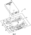
FIG. 1 is an exploded perspective view of the radio system having a portable radio coupled to an elongate mounting rail in accordance with a non-limiting example. -
FIG. 2 is a top perspective view of the sliding mount slidably receiving a corresponding elongate mounting rail as shown inFIG. 1 . -
FIG. 3 is a bottom perspective view of the sliding mount receiving the corresponding elongate mounting rail as shown inFIG. 1 . -
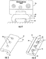
FIG. 4 is an end view of the radio system showing a handheld portable radio connected to the sliding mount in accordance with a non-limiting example. -
FIG. 5 is a top perspective view of the sliding mount as shown inFIG. 4 . -
FIG. 6 is a bottom perspective view of the sliding mount as shown inFIG. 4 . -
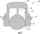
FIG. 7 is a sectional view of a ball spring plunger as shown inFIG. 4 . -
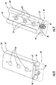
FIG. 8 is a top perspective view of another embodiment of the sliding mount in accordance with a non-limiting example. -
FIG. 9 is a bottom perspective view of the sliding mount as shown inFIG. 8 . - The present description is made with reference to the accompanying drawings, in which exemplary embodiments are shown. However, many different embodiments may be used, and thus, the description should not be construed as limited to the particular embodiments set forth herein. Rather, these embodiments are provided so that this disclosure will be thorough and complete. Like numbers refer to like elements throughout, and prime notation is used to indicate similar elements in different embodiments.
- The radio system permits a portable radio such as a handheld portable radio or a manpack portable radio, for example, such as manufactured by Harris Corporation of Melbourne, Florida, to be coupled to a mount body as part of a sliding mount that receives a corresponding elongate mounting rail. No tools are required to mount or position the portable radio on the elongate mounting rail because it slides and locks in place via an appropriate locking device. The sliding mount may also be configured to fit a mounting rail such as the standard Picatinny rail also known as the MIL-STV-1913 rail and the Standardization Agreement 2324 rail, which of course, may also mount other devices such as flashlights and laser sights.
- Referring now to
FIG. 1 , there is illustrated the radio system indicated generally at 10 that includes aportable radio 12, which in this example is a manpack portable radio. Twoelongate mounting rails 14 are supported viashock absorbers 16 on avehicle mount 18, which in turn, is mounted on avehicle surface 20. Eachelongate mounting rail 14 includes a plurality of linearly aligned, spaced apartindentations 20, also shown inFIGS. 2 and 3 , and in this example are formed as through holes, but could be formed as small recesses and not extend through theelongate mounting rail 14. Theportable radio 12 is coupled to a sliding mount indicated generally at 22 and includes amount body 24 having apassageway 26 therethrough as best shown inFIGS. 5 and 6 . Thepassageway 26 receives the correspondingelongate mounting rail 14 so that eachmount body 24 is slidable on the corresponding elongate mounting rail. Referring toFIG. 4 , instead of supporting a manpack radio coupled to twomount bodies 24 as shown inFIG. 1 , a handheld portable radio 12a in this example is coupled to only onemount body 24 that receives in itspassageway 26 anelongate mounting rail 14. - The
passageway 26 in thesliding mount 22 is preferably formed in an obround configuration, however, it is possible to form it in other configurations. In the example ofFIGS. 5 and 6 , thepassageway 26 may be formed in a specific dovetail configuration to receive anelongate mounting rail 14 that is configured as a conventional Picatinny style mounting rail, allowing themount body 24 to slide over the sharper edges of existing Picatinny rails. Themount body 24 and correspondingelongate mounting rail 14 can be formed of many different materials, including plastic or metal. Theindentations 20 may be drilled or molded as through holes or recesses depending on the techniques used to manufacture the elongate mounting rail. - Each sliding
mount 22 includes at least onespring plunger 28 carried by themount body 24 and configured to engage at least oneadjacent indentation 20 in theelongate mounting rail 14. In the example shown inFIGS. 1-6 , eachmount body 24 includes three linearly spacedspring plungers 28, which are received in orifices formed in the respective mount body. - Referring now to
FIG. 7 , eachspring plunger 28 includes ahousing 30 formed preferably of a metallic material and having anopening 32 and aninterior cavity 34 coupled thereto. Thehousing 30 is configured in its outer dimension to fit within an orifice and may include an O-ring 31 to aid in securing the housing within an orifice or be configured as a press fit. Aball 36 formed preferably of a metallic material is movable within thecavity 34 and aspring biases 38 the ball into an extended position exposed at the end opening of thehousing 30 as also shown inFIG. 6 . Depending on the number ofspring plungers 28 carried by amount body 24, the retaining force generated by the slidingmount 22 on the corresponding elongate mountingrail 14 can vary. For example, when threespring plungers 28 are arranged in spaced linear relation as illustrated, the slidingmount 22 will be retained with a greater amount of force on the corresponding elongate mountingrail 14 and be more secure. This may be advantageous in some environments where vibration or shock are present, such as imparted by a moving vehicle. In that high vibration situation, the slidingmount 22 having theportable radio 12 connected thereto may slide off the corresponding elongate mountingrail 14 if only one spring plunger was employed. If less retaining force is desired, however, then a fewer number ofspring plungers 28 could be used. - Referring now to
FIGS. 8 and 9 , the mount body may carry a locking device illustrated generally at 40'. The illustrated locking device 40' includes a lock body 42' coupled to the mount body 24' at an end thereof and a manual actuating member 44' carried by the lock body. A locking pin 46' is carried by the lock body 42' and movable between locked and unlocked positions responsive to the manual actuating member 44'. In an example, the locking device 40' includes a worm gear arrangement 48' coupling the manual actuating member 44' and the locking pin 46'. In this example, the manual actuating member 44' is formed as a rod extending traverse through the lock body 42' and includes a toothed surface that engages the worm gear arrangement 48' similar to a rack and pinion arrangement. By pressing the manual activating member 48' and in this example, the rod in one direction, the worm gear arrangement 48' is rotated slightly to move the locking pin 46' into a locked or unlocked position where the locking pin engages an indentation 20' in the mounting rail 14'. Other locking device designs may be used, including quick release pins that engage an indentation 20' or a cam driven mechanism. - Alternative designs for the
radio system 10 than those illustrated may be used. For example, the corresponding elongate mountingrail 14 may be shortened to a few inches and include a pivotally mounted attachment leg (not shown) that may be spring biased to permit the shortened elongate mountingrail 14 to be attached to a vest for temporary securement. A handheld portable radio may be mounted onto the slidingmount 22 that receives the shortened elongate mountingrail 14 having about the same length as the slidingmount 22. In this shortened version, the mountingrail 14 may be inserted within a vest pocket and held therein by the pivotally mounted attachment leg to hold the radio in a temporary position so that it may be quickly grasped. The attachment leg may be removable from the elongate mountingrail 14 to allow the mounting rail to be secured on another surface, such as a vehicle mount. In yet another example, it may be possible to attach a drive mechanism (not shown), such as an electric motor, to the side of an elongate mountingrail 14 and drive via an appropriate drive transmission the slidingmount 22 into a preferred position on the elongate mounting rail. - A method of mounting the
portable radio 12 to at least one elongate mountingrail 14 having a plurality of spaced apartindentations 20 therein is provided by slidably positioning at least one slidingmount 22 along the at least one elongate mounting rail. The at least one slidingmount 22 includes amount body 24 having apassageway 26 therethrough slidably receiving the corresponding elongate mountingrail 26 and coupled to theportable radio 12. At least one spring plunger is carried by themount body 24 and configured to engage at least oneadjacent indentation 20 in the corresponding elongate mountingrail 14. - Many modifications and other embodiments of the invention will come to the mind of one skilled in the art having the benefit of the teachings presented in the foregoing descriptions and the associated drawings. Therefore, it is understood that the invention is not to be limited to the specific embodiments disclosed, and that modifications and embodiments are intended to be included within the scope of the appended claims.
Claims (9)
- A radio system (10) comprising:a portable radio (12);at least one elongate mounting rail (14) having a plurality of spaced apart indentations therein; andat least one sliding mount (22) comprising a mount body (24) having a passageway (26) therethrough slidably receiving a corresponding elongate mounting rail (14), and coupled to said portable radio (12), each sliding mount (22) comprising at least one orifice extending into the passageway (26), andat least one spring plunger (28) carried by said mount body (24) and configured to engage at least one adjacent indentation in said corresponding elongate mounting rail (14);characterized in that the at least one spring plunger (28) comprisesa housing (30) having an opening (32) and an interior cavity (34) coupled thereto, and an O-ring on the housing to aid in securing the housing within the orifice, wherein said housing (30) is configured in its outer dimension to the O-ring (31),a ball (36) movable within the cavity (34), anda spring (38) biasing said ball to an extended position exposed at the end opening of said housing.
- The radio system (10) according to claim 1 further comprising a locking device (40') carried by said mount body (24) to lock said mount body (24) to said corresponding elongate mounting rail (14).
- The radio system (10) according to claim 2 wherein said locking device (40') comprises:a lock body (42') coupled to said mount body (24) at an end thereof;a manual actuating member (44') carried by said lock body (42'); anda locking pin (46) carried by said lock body (42') and moveable between locked and unlocked positions responsive to said manual actuating member (44').
- The radio system (10) according to claim 3 wherein said locking device (40') further comprises a worm gear arrangement (48') coupling said manual actuating member (44') and said locking pin (46).
- A sliding mount (22) for an elongate mounting rail (14) having a plurality of spaced apart indentations therein and comprising:a mount body (24) having a passageway (26) therethrough slidably receiving the elongate mounting rail (14), and coupled to a portable radio (12);at least one orifice extending into the passageway (26); andat least one spring ball plunger (28) carried by said mount body (24) and configured to engage at least one adjacent indentation in the elongate mounting rail (14);said spring ball plunger (28) comprisinga housing (30) having an end opening (32) and an interior cavity (34) coupled thereto, and an O-ring on the housing to aid in securing the housing within the orifice, wherein said housing (30) is configured in its outer dimension to the O-ring (31),a ball (36) moveable within the cavity (34), anda spring (38) biasing said ball to an extended position exposed at the end opening of said housing.
- The sliding mount (22) according to claim 5 further comprising a locking device (40') carried by said mount body (24) to lock said mount body (24) to said corresponding elongate mounting rail (14).
- The sliding mount (22) according to claim 6 wherein said locking device (40') comprises:a lock body (42') coupled to said mount body (24) at an end thereof;a manual actuating member (44') carried by said lock body (42'); anda locking pin (46) carried by said lock body (42') and moveable between locked and unlocked positions responsive to said manual actuating member (44').
- The sliding mount (22) according to claim 7 wherein said locking device (40') further comprises a worm gear arrangement (48') coupling said manual actuating member (44') and said locking pin (46).
- The sliding mount (22) according to claim 5 wherein said at least one spring ball plunger (28) comprises three spring ball plungers (28) arranged in spaced relation.
Applications Claiming Priority (1)
| Application Number | Priority Date | Filing Date | Title |
|---|---|---|---|
| US15/715,213 US10119786B1 (en) | 2017-09-26 | 2017-09-26 | Radio system having a sliding mount for a portable radio and related methods |
Publications (2)
| Publication Number | Publication Date |
|---|---|
| EP3461010A1 EP3461010A1 (en) | 2019-03-27 |
| EP3461010B1 true EP3461010B1 (en) | 2020-04-01 |
Family
ID=63678476
Family Applications (1)
| Application Number | Title | Priority Date | Filing Date |
|---|---|---|---|
| EP18195929.7A Active EP3461010B1 (en) | 2017-09-26 | 2018-09-21 | Radio system having a sliding mount for a portable radio and related methods |
Country Status (3)
| Country | Link |
|---|---|
| US (1) | US10119786B1 (en) |
| EP (1) | EP3461010B1 (en) |
| IL (1) | IL260467B (en) |
Families Citing this family (1)
| Publication number | Priority date | Publication date | Assignee | Title |
|---|---|---|---|---|
| US10921096B2 (en) * | 2017-09-30 | 2021-02-16 | Robert E. Stewart | Mounting and fastening system and mounting adapter |
Family Cites Families (12)
| Publication number | Priority date | Publication date | Assignee | Title |
|---|---|---|---|---|
| US5174223A (en) * | 1989-09-20 | 1992-12-29 | Nagy Marta K | Ergonomically designed computer workstation adjustable to various sitting and standing positions |
| US20040000083A1 (en) | 2002-07-01 | 2004-01-01 | Grant James Emmett | Multiple rail adapter |
| US7222451B2 (en) | 2004-02-12 | 2007-05-29 | Da Keng | Quick disconnect bipod mount and clamp assembly |
| KR100816505B1 (en) * | 2005-09-09 | 2008-03-24 | 배석희 | Laptop Table |
| US20090167634A1 (en) * | 2007-12-28 | 2009-07-02 | Evga Corporation | Systems having detachable twin display monitors |
| US8499484B2 (en) | 2011-02-17 | 2013-08-06 | LW Schneider Incorporated | Assembly for mounting on a picatinny-type rail |
| CA2781357A1 (en) | 2012-06-28 | 2013-12-28 | Lorenzo Zappia | Hawk for retaining tools |
| US9622529B2 (en) | 2012-07-18 | 2017-04-18 | Wilcox Industries Corp. | Helmet edge trim wiring harness |
| US20140252187A1 (en) | 2013-02-05 | 2014-09-11 | Cody Petrovic | Modular mounting system using picatinny-type rail |
| US9632187B2 (en) | 2013-06-12 | 2017-04-25 | The Regents Of The University Of California | Modular positron emission tomography kit |
| US9591255B2 (en) | 2014-07-18 | 2017-03-07 | Solid Proof Technologies LLC | Emergency assistance method and device for a firearm |
| US9599430B1 (en) | 2015-08-25 | 2017-03-21 | WHG Properties, LLC | Firearm handguard |
-
2017
- 2017-09-26 US US15/715,213 patent/US10119786B1/en active Active
-
2018
- 2018-07-08 IL IL260467A patent/IL260467B/en active IP Right Grant
- 2018-09-21 EP EP18195929.7A patent/EP3461010B1/en active Active
Non-Patent Citations (1)
| Title |
|---|
| None * |
Also Published As
| Publication number | Publication date |
|---|---|
| IL260467B (en) | 2019-03-31 |
| EP3461010A1 (en) | 2019-03-27 |
| US10119786B1 (en) | 2018-11-06 |
Similar Documents
| Publication | Publication Date | Title |
|---|---|---|
| US8499485B2 (en) | Sliding mount adapter device | |
| US8327574B2 (en) | System for mounting an accessory to a firearm | |
| US8276307B2 (en) | Mount adapter device utilizing a push system | |
| US9664479B1 (en) | Adjustable firearm stock | |
| US9664476B1 (en) | Adjustable firearm stock | |
| EP3081840B1 (en) | Locking apparatus | |
| EP3407006B1 (en) | A kinematic rail mount for mounting a device on a firearm rail | |
| US9453707B2 (en) | Systems and methods for a scope mount assembly | |
| US6517133B2 (en) | Sighting mount device | |
| US20190056195A1 (en) | Equipment retention system | |
| US7703231B2 (en) | Gun attachment holder | |
| US8793921B1 (en) | Tangent integrated tilt sight | |
| EP4166896A1 (en) | Modular hybrid dovetail rail clamping assembly | |
| US20040244259A1 (en) | Mounting assembly for a weapon accessory | |
| US9573268B2 (en) | Swivel handle assembly | |
| US20140096429A1 (en) | System for mounting an accessory to a firearm | |
| US6385892B1 (en) | Bayonet lug clamp and mount assembly | |
| US9784527B2 (en) | Securing platform accessories | |
| US20060162227A1 (en) | Pivoting mount for a firearm accessory | |
| DK3106826T3 (en) | Adapter piece and handgun with such adapter piece | |
| US20060207156A1 (en) | Mount for firearm sighting device having throw-lever clamp and lever safety latch | |
| EP3407005B1 (en) | A kinematic rail mount for mounting a device on a firearm rail | |
| US10458746B2 (en) | Adjustable cheek riser | |
| WO2006069092A3 (en) | Indexed optical fiber connector | |
| US20170261288A1 (en) | Technologies for firearm accessory mounting |
Legal Events
| Date | Code | Title | Description |
|---|---|---|---|
| PUAI | Public reference made under article 153(3) epc to a published international application that has entered the european phase |
Free format text: ORIGINAL CODE: 0009012 |
|
| STAA | Information on the status of an ep patent application or granted ep patent |
Free format text: STATUS: REQUEST FOR EXAMINATION WAS MADE |
|
| 17P | Request for examination filed |
Effective date: 20180921 |
|
| AK | Designated contracting states |
Kind code of ref document: A1 Designated state(s): AL AT BE BG CH CY CZ DE DK EE ES FI FR GB GR HR HU IE IS IT LI LT LU LV MC MK MT NL NO PL PT RO RS SE SI SK SM TR |
|
| AX | Request for extension of the european patent |
Extension state: BA ME |
|
| GRAP | Despatch of communication of intention to grant a patent |
Free format text: ORIGINAL CODE: EPIDOSNIGR1 |
|
| STAA | Information on the status of an ep patent application or granted ep patent |
Free format text: STATUS: GRANT OF PATENT IS INTENDED |
|
| INTG | Intention to grant announced |
Effective date: 20191029 |
|
| GRAS | Grant fee paid |
Free format text: ORIGINAL CODE: EPIDOSNIGR3 |
|
| GRAA | (expected) grant |
Free format text: ORIGINAL CODE: 0009210 |
|
| STAA | Information on the status of an ep patent application or granted ep patent |
Free format text: STATUS: THE PATENT HAS BEEN GRANTED |
|
| AK | Designated contracting states |
Kind code of ref document: B1 Designated state(s): AL AT BE BG CH CY CZ DE DK EE ES FI FR GB GR HR HU IE IS IT LI LT LU LV MC MK MT NL NO PL PT RO RS SE SI SK SM TR |
|
| REG | Reference to a national code |
Ref country code: GB Ref legal event code: FG4D |
|
| REG | Reference to a national code |
Ref country code: CH Ref legal event code: EP Ref country code: AT Ref legal event code: REF Ref document number: 1252697 Country of ref document: AT Kind code of ref document: T Effective date: 20200415 |
|
| REG | Reference to a national code |
Ref country code: DE Ref legal event code: R096 Ref document number: 602018003428 Country of ref document: DE |
|
| REG | Reference to a national code |
Ref country code: IE Ref legal event code: FG4D |
|
| PG25 | Lapsed in a contracting state [announced via postgrant information from national office to epo] |
Ref country code: BG Free format text: LAPSE BECAUSE OF FAILURE TO SUBMIT A TRANSLATION OF THE DESCRIPTION OR TO PAY THE FEE WITHIN THE PRESCRIBED TIME-LIMIT Effective date: 20200701 |
|
| REG | Reference to a national code |
Ref country code: NL Ref legal event code: MP Effective date: 20200401 |
|
| REG | Reference to a national code |
Ref country code: DE Ref legal event code: R082 Ref document number: 602018003428 Country of ref document: DE Representative=s name: WUESTHOFF & WUESTHOFF, PATENTANWAELTE PARTG MB, DE Ref country code: DE Ref legal event code: R081 Ref document number: 602018003428 Country of ref document: DE Owner name: HARRIS GLOBAL COMMUNICATIONS, INC., ROCHESTER, US Free format text: FORMER OWNER: HARRIS SOLUTIONS NY, INC., ROCHESTER, NY, US |
|
| REG | Reference to a national code |
Ref country code: LT Ref legal event code: MG4D |
|
| PG25 | Lapsed in a contracting state [announced via postgrant information from national office to epo] |
Ref country code: NO Free format text: LAPSE BECAUSE OF FAILURE TO SUBMIT A TRANSLATION OF THE DESCRIPTION OR TO PAY THE FEE WITHIN THE PRESCRIBED TIME-LIMIT Effective date: 20200701 Ref country code: LT Free format text: LAPSE BECAUSE OF FAILURE TO SUBMIT A TRANSLATION OF THE DESCRIPTION OR TO PAY THE FEE WITHIN THE PRESCRIBED TIME-LIMIT Effective date: 20200401 Ref country code: PT Free format text: LAPSE BECAUSE OF FAILURE TO SUBMIT A TRANSLATION OF THE DESCRIPTION OR TO PAY THE FEE WITHIN THE PRESCRIBED TIME-LIMIT Effective date: 20200817 Ref country code: FI Free format text: LAPSE BECAUSE OF FAILURE TO SUBMIT A TRANSLATION OF THE DESCRIPTION OR TO PAY THE FEE WITHIN THE PRESCRIBED TIME-LIMIT Effective date: 20200401 Ref country code: IS Free format text: LAPSE BECAUSE OF FAILURE TO SUBMIT A TRANSLATION OF THE DESCRIPTION OR TO PAY THE FEE WITHIN THE PRESCRIBED TIME-LIMIT Effective date: 20200801 Ref country code: SE Free format text: LAPSE BECAUSE OF FAILURE TO SUBMIT A TRANSLATION OF THE DESCRIPTION OR TO PAY THE FEE WITHIN THE PRESCRIBED TIME-LIMIT Effective date: 20200401 Ref country code: GR Free format text: LAPSE BECAUSE OF FAILURE TO SUBMIT A TRANSLATION OF THE DESCRIPTION OR TO PAY THE FEE WITHIN THE PRESCRIBED TIME-LIMIT Effective date: 20200702 Ref country code: CZ Free format text: LAPSE BECAUSE OF FAILURE TO SUBMIT A TRANSLATION OF THE DESCRIPTION OR TO PAY THE FEE WITHIN THE PRESCRIBED TIME-LIMIT Effective date: 20200401 Ref country code: NL Free format text: LAPSE BECAUSE OF FAILURE TO SUBMIT A TRANSLATION OF THE DESCRIPTION OR TO PAY THE FEE WITHIN THE PRESCRIBED TIME-LIMIT Effective date: 20200401 |
|
| REG | Reference to a national code |
Ref country code: AT Ref legal event code: MK05 Ref document number: 1252697 Country of ref document: AT Kind code of ref document: T Effective date: 20200401 |
|
| PG25 | Lapsed in a contracting state [announced via postgrant information from national office to epo] |
Ref country code: RS Free format text: LAPSE BECAUSE OF FAILURE TO SUBMIT A TRANSLATION OF THE DESCRIPTION OR TO PAY THE FEE WITHIN THE PRESCRIBED TIME-LIMIT Effective date: 20200401 Ref country code: LV Free format text: LAPSE BECAUSE OF FAILURE TO SUBMIT A TRANSLATION OF THE DESCRIPTION OR TO PAY THE FEE WITHIN THE PRESCRIBED TIME-LIMIT Effective date: 20200401 Ref country code: HR Free format text: LAPSE BECAUSE OF FAILURE TO SUBMIT A TRANSLATION OF THE DESCRIPTION OR TO PAY THE FEE WITHIN THE PRESCRIBED TIME-LIMIT Effective date: 20200401 |
|
| PG25 | Lapsed in a contracting state [announced via postgrant information from national office to epo] |
Ref country code: AL Free format text: LAPSE BECAUSE OF FAILURE TO SUBMIT A TRANSLATION OF THE DESCRIPTION OR TO PAY THE FEE WITHIN THE PRESCRIBED TIME-LIMIT Effective date: 20200401 |
|
| REG | Reference to a national code |
Ref country code: DE Ref legal event code: R097 Ref document number: 602018003428 Country of ref document: DE |
|
| PG25 | Lapsed in a contracting state [announced via postgrant information from national office to epo] |
Ref country code: ES Free format text: LAPSE BECAUSE OF FAILURE TO SUBMIT A TRANSLATION OF THE DESCRIPTION OR TO PAY THE FEE WITHIN THE PRESCRIBED TIME-LIMIT Effective date: 20200401 Ref country code: SM Free format text: LAPSE BECAUSE OF FAILURE TO SUBMIT A TRANSLATION OF THE DESCRIPTION OR TO PAY THE FEE WITHIN THE PRESCRIBED TIME-LIMIT Effective date: 20200401 Ref country code: DK Free format text: LAPSE BECAUSE OF FAILURE TO SUBMIT A TRANSLATION OF THE DESCRIPTION OR TO PAY THE FEE WITHIN THE PRESCRIBED TIME-LIMIT Effective date: 20200401 Ref country code: AT Free format text: LAPSE BECAUSE OF FAILURE TO SUBMIT A TRANSLATION OF THE DESCRIPTION OR TO PAY THE FEE WITHIN THE PRESCRIBED TIME-LIMIT Effective date: 20200401 Ref country code: RO Free format text: LAPSE BECAUSE OF FAILURE TO SUBMIT A TRANSLATION OF THE DESCRIPTION OR TO PAY THE FEE WITHIN THE PRESCRIBED TIME-LIMIT Effective date: 20200401 Ref country code: EE Free format text: LAPSE BECAUSE OF FAILURE TO SUBMIT A TRANSLATION OF THE DESCRIPTION OR TO PAY THE FEE WITHIN THE PRESCRIBED TIME-LIMIT Effective date: 20200401 |
|
| PLBE | No opposition filed within time limit |
Free format text: ORIGINAL CODE: 0009261 |
|
| STAA | Information on the status of an ep patent application or granted ep patent |
Free format text: STATUS: NO OPPOSITION FILED WITHIN TIME LIMIT |
|
| PG25 | Lapsed in a contracting state [announced via postgrant information from national office to epo] |
Ref country code: PL Free format text: LAPSE BECAUSE OF FAILURE TO SUBMIT A TRANSLATION OF THE DESCRIPTION OR TO PAY THE FEE WITHIN THE PRESCRIBED TIME-LIMIT Effective date: 20200401 Ref country code: SK Free format text: LAPSE BECAUSE OF FAILURE TO SUBMIT A TRANSLATION OF THE DESCRIPTION OR TO PAY THE FEE WITHIN THE PRESCRIBED TIME-LIMIT Effective date: 20200401 |
|
| 26N | No opposition filed |
Effective date: 20210112 |
|
| PG25 | Lapsed in a contracting state [announced via postgrant information from national office to epo] |
Ref country code: SI Free format text: LAPSE BECAUSE OF FAILURE TO SUBMIT A TRANSLATION OF THE DESCRIPTION OR TO PAY THE FEE WITHIN THE PRESCRIBED TIME-LIMIT Effective date: 20200401 |
|
| REG | Reference to a national code |
Ref country code: BE Ref legal event code: MM Effective date: 20200930 |
|
| PG25 | Lapsed in a contracting state [announced via postgrant information from national office to epo] |
Ref country code: LU Free format text: LAPSE BECAUSE OF NON-PAYMENT OF DUE FEES Effective date: 20200921 |
|
| PG25 | Lapsed in a contracting state [announced via postgrant information from national office to epo] |
Ref country code: BE Free format text: LAPSE BECAUSE OF NON-PAYMENT OF DUE FEES Effective date: 20200930 Ref country code: IE Free format text: LAPSE BECAUSE OF NON-PAYMENT OF DUE FEES Effective date: 20200921 |
|
| REG | Reference to a national code |
Ref country code: CH Ref legal event code: PL |
|
| PG25 | Lapsed in a contracting state [announced via postgrant information from national office to epo] |
Ref country code: TR Free format text: LAPSE BECAUSE OF FAILURE TO SUBMIT A TRANSLATION OF THE DESCRIPTION OR TO PAY THE FEE WITHIN THE PRESCRIBED TIME-LIMIT Effective date: 20200401 Ref country code: MT Free format text: LAPSE BECAUSE OF FAILURE TO SUBMIT A TRANSLATION OF THE DESCRIPTION OR TO PAY THE FEE WITHIN THE PRESCRIBED TIME-LIMIT Effective date: 20200401 Ref country code: CY Free format text: LAPSE BECAUSE OF FAILURE TO SUBMIT A TRANSLATION OF THE DESCRIPTION OR TO PAY THE FEE WITHIN THE PRESCRIBED TIME-LIMIT Effective date: 20200401 |
|
| PG25 | Lapsed in a contracting state [announced via postgrant information from national office to epo] |
Ref country code: MK Free format text: LAPSE BECAUSE OF FAILURE TO SUBMIT A TRANSLATION OF THE DESCRIPTION OR TO PAY THE FEE WITHIN THE PRESCRIBED TIME-LIMIT Effective date: 20200401 Ref country code: MC Free format text: LAPSE BECAUSE OF FAILURE TO SUBMIT A TRANSLATION OF THE DESCRIPTION OR TO PAY THE FEE WITHIN THE PRESCRIBED TIME-LIMIT Effective date: 20200401 |
|
| PG25 | Lapsed in a contracting state [announced via postgrant information from national office to epo] |
Ref country code: LI Free format text: LAPSE BECAUSE OF NON-PAYMENT OF DUE FEES Effective date: 20210930 Ref country code: CH Free format text: LAPSE BECAUSE OF NON-PAYMENT OF DUE FEES Effective date: 20210930 |
|
| P01 | Opt-out of the competence of the unified patent court (upc) registered |
Effective date: 20230530 |
|
| PGFP | Annual fee paid to national office [announced via postgrant information from national office to epo] |
Ref country code: DE Payment date: 20250929 Year of fee payment: 8 |
|
| PGFP | Annual fee paid to national office [announced via postgrant information from national office to epo] |
Ref country code: IT Payment date: 20250919 Year of fee payment: 8 |
|
| PGFP | Annual fee paid to national office [announced via postgrant information from national office to epo] |
Ref country code: GB Payment date: 20250929 Year of fee payment: 8 |
|
| PGFP | Annual fee paid to national office [announced via postgrant information from national office to epo] |
Ref country code: FR Payment date: 20250925 Year of fee payment: 8 |