EP3460958B1 - Oil circulation type motor and eco vehicle including the same - Google Patents
Oil circulation type motor and eco vehicle including the same Download PDFInfo
- Publication number
- EP3460958B1 EP3460958B1 EP18162520.3A EP18162520A EP3460958B1 EP 3460958 B1 EP3460958 B1 EP 3460958B1 EP 18162520 A EP18162520 A EP 18162520A EP 3460958 B1 EP3460958 B1 EP 3460958B1
- Authority
- EP
- European Patent Office
- Prior art keywords
- bobbin
- cooling oil
- oil
- internal
- stator
- Prior art date
- Legal status (The legal status is an assumption and is not a legal conclusion. Google has not performed a legal analysis and makes no representation as to the accuracy of the status listed.)
- Active
Links
Images



Classifications
-
- H—ELECTRICITY
- H02—GENERATION; CONVERSION OR DISTRIBUTION OF ELECTRIC POWER
- H02K—DYNAMO-ELECTRIC MACHINES
- H02K1/00—Details of the magnetic circuit
- H02K1/06—Details of the magnetic circuit characterised by the shape, form or construction
- H02K1/12—Stationary parts of the magnetic circuit
- H02K1/20—Stationary parts of the magnetic circuit with channels or ducts for flow of cooling medium
-
- H—ELECTRICITY
- H02—GENERATION; CONVERSION OR DISTRIBUTION OF ELECTRIC POWER
- H02K—DYNAMO-ELECTRIC MACHINES
- H02K9/00—Arrangements for cooling or ventilating
- H02K9/19—Arrangements for cooling or ventilating for machines with closed casing and closed-circuit cooling using a liquid cooling medium, e.g. oil
- H02K9/197—Arrangements for cooling or ventilating for machines with closed casing and closed-circuit cooling using a liquid cooling medium, e.g. oil in which the rotor or stator space is fluid-tight, e.g. to provide for different cooling media for rotor and stator
-
- H—ELECTRICITY
- H02—GENERATION; CONVERSION OR DISTRIBUTION OF ELECTRIC POWER
- H02K—DYNAMO-ELECTRIC MACHINES
- H02K3/00—Details of windings
- H02K3/04—Windings characterised by the conductor shape, form or construction, e.g. with bar conductors
- H02K3/24—Windings characterised by the conductor shape, form or construction, e.g. with bar conductors with channels or ducts for cooling medium between the conductors
-
- B—PERFORMING OPERATIONS; TRANSPORTING
- B60—VEHICLES IN GENERAL
- B60K—ARRANGEMENT OR MOUNTING OF PROPULSION UNITS OR OF TRANSMISSIONS IN VEHICLES; ARRANGEMENT OR MOUNTING OF PLURAL DIVERSE PRIME-MOVERS IN VEHICLES; AUXILIARY DRIVES FOR VEHICLES; INSTRUMENTATION OR DASHBOARDS FOR VEHICLES; ARRANGEMENTS IN CONNECTION WITH COOLING, AIR INTAKE, GAS EXHAUST OR FUEL SUPPLY OF PROPULSION UNITS IN VEHICLES
- B60K11/00—Arrangement in connection with cooling of propulsion units
- B60K11/02—Arrangement in connection with cooling of propulsion units with liquid cooling
-
- H—ELECTRICITY
- H02—GENERATION; CONVERSION OR DISTRIBUTION OF ELECTRIC POWER
- H02K—DYNAMO-ELECTRIC MACHINES
- H02K1/00—Details of the magnetic circuit
- H02K1/06—Details of the magnetic circuit characterised by the shape, form or construction
- H02K1/12—Stationary parts of the magnetic circuit
-
- H—ELECTRICITY
- H02—GENERATION; CONVERSION OR DISTRIBUTION OF ELECTRIC POWER
- H02K—DYNAMO-ELECTRIC MACHINES
- H02K3/00—Details of windings
- H02K3/32—Windings characterised by the shape, form or construction of the insulation
- H02K3/325—Windings characterised by the shape, form or construction of the insulation for windings on salient poles, such as claw-shaped poles
-
- H—ELECTRICITY
- H02—GENERATION; CONVERSION OR DISTRIBUTION OF ELECTRIC POWER
- H02K—DYNAMO-ELECTRIC MACHINES
- H02K3/00—Details of windings
- H02K3/46—Fastening of windings on the stator or rotor structure
-
- H—ELECTRICITY
- H02—GENERATION; CONVERSION OR DISTRIBUTION OF ELECTRIC POWER
- H02K—DYNAMO-ELECTRIC MACHINES
- H02K5/00—Casings; Enclosures; Supports
- H02K5/04—Casings or enclosures characterised by the shape, form or construction thereof
- H02K5/20—Casings or enclosures characterised by the shape, form or construction thereof with channels or ducts for flow of cooling medium
- H02K5/203—Casings or enclosures characterised by the shape, form or construction thereof with channels or ducts for flow of cooling medium specially adapted for liquids, e.g. cooling jackets
-
- H—ELECTRICITY
- H02—GENERATION; CONVERSION OR DISTRIBUTION OF ELECTRIC POWER
- H02K—DYNAMO-ELECTRIC MACHINES
- H02K7/00—Arrangements for handling mechanical energy structurally associated with dynamo-electric machines, e.g. structural association with mechanical driving motors or auxiliary dynamo-electric machines
- H02K7/006—Structural association of a motor or generator with the drive train of a motor vehicle
-
- B—PERFORMING OPERATIONS; TRANSPORTING
- B60—VEHICLES IN GENERAL
- B60K—ARRANGEMENT OR MOUNTING OF PROPULSION UNITS OR OF TRANSMISSIONS IN VEHICLES; ARRANGEMENT OR MOUNTING OF PLURAL DIVERSE PRIME-MOVERS IN VEHICLES; AUXILIARY DRIVES FOR VEHICLES; INSTRUMENTATION OR DASHBOARDS FOR VEHICLES; ARRANGEMENTS IN CONNECTION WITH COOLING, AIR INTAKE, GAS EXHAUST OR FUEL SUPPLY OF PROPULSION UNITS IN VEHICLES
- B60K1/00—Arrangement or mounting of electrical propulsion units
- B60K2001/003—Arrangement or mounting of electrical propulsion units with means for cooling the electrical propulsion units
- B60K2001/006—Arrangement or mounting of electrical propulsion units with means for cooling the electrical propulsion units the electric motors
-
- B—PERFORMING OPERATIONS; TRANSPORTING
- B60—VEHICLES IN GENERAL
- B60Y—INDEXING SCHEME RELATING TO ASPECTS CROSS-CUTTING VEHICLE TECHNOLOGY
- B60Y2200/00—Type of vehicle
- B60Y2200/90—Vehicles comprising electric prime movers
-
- B—PERFORMING OPERATIONS; TRANSPORTING
- B60—VEHICLES IN GENERAL
- B60Y—INDEXING SCHEME RELATING TO ASPECTS CROSS-CUTTING VEHICLE TECHNOLOGY
- B60Y2200/00—Type of vehicle
- B60Y2200/90—Vehicles comprising electric prime movers
- B60Y2200/91—Electric vehicles
-
- H—ELECTRICITY
- H02—GENERATION; CONVERSION OR DISTRIBUTION OF ELECTRIC POWER
- H02K—DYNAMO-ELECTRIC MACHINES
- H02K2203/00—Specific aspects not provided for in the other groups of this subclass relating to the windings
- H02K2203/12—Machines characterised by the bobbins for supporting the windings
-
- H—ELECTRICITY
- H02—GENERATION; CONVERSION OR DISTRIBUTION OF ELECTRIC POWER
- H02K—DYNAMO-ELECTRIC MACHINES
- H02K2205/00—Specific aspects not provided for in the other groups of this subclass relating to casings, enclosures, supports
- H02K2205/09—Machines characterised by drain passages or by venting, breathing or pressure compensating means
-
- Y—GENERAL TAGGING OF NEW TECHNOLOGICAL DEVELOPMENTS; GENERAL TAGGING OF CROSS-SECTIONAL TECHNOLOGIES SPANNING OVER SEVERAL SECTIONS OF THE IPC; TECHNICAL SUBJECTS COVERED BY FORMER USPC CROSS-REFERENCE ART COLLECTIONS [XRACs] AND DIGESTS
- Y02—TECHNOLOGIES OR APPLICATIONS FOR MITIGATION OR ADAPTATION AGAINST CLIMATE CHANGE
- Y02T—CLIMATE CHANGE MITIGATION TECHNOLOGIES RELATED TO TRANSPORTATION
- Y02T10/00—Road transport of goods or passengers
- Y02T10/60—Other road transportation technologies with climate change mitigation effect
- Y02T10/62—Hybrid vehicles
-
- Y—GENERAL TAGGING OF NEW TECHNOLOGICAL DEVELOPMENTS; GENERAL TAGGING OF CROSS-SECTIONAL TECHNOLOGIES SPANNING OVER SEVERAL SECTIONS OF THE IPC; TECHNICAL SUBJECTS COVERED BY FORMER USPC CROSS-REFERENCE ART COLLECTIONS [XRACs] AND DIGESTS
- Y02—TECHNOLOGIES OR APPLICATIONS FOR MITIGATION OR ADAPTATION AGAINST CLIMATE CHANGE
- Y02T—CLIMATE CHANGE MITIGATION TECHNOLOGIES RELATED TO TRANSPORTATION
- Y02T10/00—Road transport of goods or passengers
- Y02T10/60—Other road transportation technologies with climate change mitigation effect
- Y02T10/64—Electric machine technologies in electromobility
Definitions
- the present invention relates to a motor cooling structure, and particularly, to an echo vehicle including a motor in which cooling is performed by oil circulating through a coil.
- an echo vehicle may include a hybrid electric vehicle (HEV) using an engine and motor as a power source, an electric vehicle (EV) using a motor as a power source, and a fuel cell electric vehicle (FCEV) using a fuel cell as a power source.
- HEV hybrid electric vehicle
- EV electric vehicle
- FCEV fuel cell electric vehicle
- the HEV is divided into a plug-in hybrid electric vehicle (PHEV) to which a double clutch transmission (DCT) is applied and a transmission mounted electric device (TMED) to which a motor and a hybrid starter & generator (HSG) are separately applied.
- PHEV plug-in hybrid electric vehicle
- TMED transmission mounted electric device
- HSG hybrid starter & generator
- a motor used in an echo vehicle necessarily may include a stator and rotor and a cooling structure for cooling heat which is generated through a current applied to a coil and an eddy current caused by a counter electromotive voltage.
- Examples of the cooling structure may include an oil spraying method for spraying auto transmission oil as cooling oil onto a rotor sleeve and a bobbin.
- the oil sprayed onto the bobbin cools the coil wound around the bobbin during operation.
- a thermal damage can be prevented while the performance of the motor is maintained.
- the oil spraying method sprays oil only when the motor is rotated, but does not spray oil when the motor is stopped.
- the cooling performance is inevitably degraded.
- an oil direct injection method using a cooling pipe through which oil directly flows to a coil may be combined with the oil spraying method.
- the use of the oil direction injection method is limited depending on a coil winding method of the motor.
- a distributed winding type motor has a structure in which coils protrude from both end portions of a stator.
- oil injected by point oil injection at the top portions of the coils through a cooling pipe may directly flow to the coils, exhibiting sufficient cooling performance.
- a concentrated winding type motor has a structural limitation in that oil injected by point oil injection at the top portions of the coils does not come in uniform contact with the individual coils.
- the concentrated winding type motor since the concentrated winding type motor has a parallel winding structure in which the coils are separately wound for the respective teeth of a stator, the oil injected by the point oil injection at the top portions of the coils through the cooling pipe cannot come in uniform contact with the individual coils, and thus has difficulties in cooling the whole coils. Therefore, the concentrated winding type motor is required to overcome the limitation of the oil spraying method in which the moving direction of the oil scattered from the rotor is blocked by the bobbin such that the scattered oil cannot be supplied to a side surface of the coil with a large area while coming in direct contact with the coil, and the limitation of the oil direction injection method in which oil does not come in uniform contact with the individual coils.
- US 2017/0063201 A1 discloses an electric motor capable of cooling a stator without being increased in size with a small number of components and even with simple work.
- US 2009/0183591 A1 discloses a rotating electrical machine that includes: a stator including a stator core and a teeth section, with a stator coil wound at the teeth section; a rotor arranged via a clearance at an inner periphery side of the stator and supported in a freely rotating manner; and a distribution unit supported by a resin holder, and including a conductor connected to the stator coil.
- Both US2003/057797 A1 and EP1215800 A2 disclose an electric motor comprising a stator and a cooling circuit wherein cooling oil is transferred from a front axial end of the stator to a rear axial end of the stator, so as to wet and cool the stator coils.
- the present invention refers to the concentrated winding type motor of independent claim 1.
- Optional features are recited in the dependent claim 2.
- the present invention is are directed to providing an oil circulation type motor, which circulates oil which is filled while surrounding a stator coil, and thus significantly increases coil cooling efficiency, compared to an oil spraying method having low cooling performance and an oil direct injection method of which the use is limited depending on a coil winding method, and an echo vehicle including the same.
- the present invention is directed to providing an oil circulation type motor which is configured for achieving an increase of capacity and an improvement of output density through higher cooling efficiency than the oil spraying method and the oil direct injection method, and thus suitable for a concentrated winding type motor configured for a TMED, and an echo vehicle including the same.
- a motor includes an oil circulating device having cooling oil chambers formed along the circumference of a stator core, wherein cooling oil is introduced into the cooling oil chambers, wets a stator coil wound around the stator core, and is then discharged from the cooling oil chambers.
- the cooling oil is discharged from the cooling oil chambers under the effect of the gravity, wherein the cooling oil chambers are formed at both sides of the stator core, respectively, while communicating with each other.
- Each of the cooling oil chambers has an inlet hole into which the cooling oil is introduced and an outlet hole from which the cooling oil is discharged.
- the inlet hole may be connected to an inlet pipe, and the inlet pipe may supply the cooling oil to a space around the stator core.
- Each of the cooling oil chambers is formed by a bobbin coupled to the stator core and located at the stator coil and a cooling case coupled to the bobbin to cover the stator coil.
- the bobbin and the cooling case may be fixed through an insertion structure or a clip structure.
- the bobbin may be coupled to the stator core while being located at each of teeth which are radially disposed and have the stator coil wound therearound, and the bobbins adjacent to each other in the radial arrangement of the teeth may be connected to each other through any one of a butt connection structure, a wedge connection structure, a round connection structure and an insertion connection structure.
- the wedge connection structure may include an engagement between a wedge groove and a wedge protrusion
- the round connection structure may include an engagement between a hemispherical groove and a hemispherical protrusion
- the insertion connection structure may include an engagement between a linear groove and a linear protrusion
- the stator core forms a stator which may include a support ring covering the stator core and a terminal holder coupled to the support ring to supply power to the stator coil through a terminal.
- the support ring may cover the external circumference of the stator core to expose the stator coil through the left and right sides of the stator core.
- an eco vehicle may include: a motor having an oil circulating device which directly cools a stator coil of a stator using cooling oil while the cooling oil is introduced and discharged; and an oil pump pumping the cooling oil to supply to the oil circulating device.
- the oil circulating device circulates the cooling oil through the front and rear portions of the stator.
- the motor includes a concentrated winding type motor.
- the motor may include an inlet pipe connected to the oil pump through the oil coil circulating device in order to supply the cooling oil.
- a motor 1 includes a stator 2 to which power is applied and an oil circulating device 10, and performs a cooling operation on the stator 2 through an oil circulation type cooling structure.
- the stator 2 includes a stator core 3, a stator coil 4, a support ring 5 and a terminal holder 6.
- the stator core 3 has teeth 3a disposed at even intervals in a radial shape, the stator coil 4 is wound around each of the teeth 3a such that a current flows therethrough, the support ring 5 is coupled to the stator core 3 while surrounding the stator core 3, and the terminal holder 6 is coupled to the rear of the support ring 5 to supply power to a terminal 6a. Therefore, the stator 2 is coupled to a rotor (refer to FIG. 7 ) in an internal space of the stator core 3.
- the oil circulating device 10 includes a bobbin 20 having two pairs of internal and external bobbins 20A and 20B, a cooling case 30 having front and rear bobbin covers 30A and 30B, and cooling oil circulation holes 31 and 32.
- One pair of internal and external bobbins 20A and 20B are coupled to the front bobbin cover 30A at the front of the stator coil 4, and the other pair of internal and external bobbins 20A and 20B are coupled to the rear bobbin cover 30B at the rear of the stator coil 4.
- the cooling oil circulation holes are divided into an inlet hole 31 and an outlet hole 32.
- the inlet hole 31 is configured as an entrance through cooling oil is introduced into the one pair of internal and external bobbins 20A and 20B and a front cooling oil filled space of the front bobbin cover 30A
- the outlet hole 32 is configured as an exit through which cooling oil is discharged from the front cooling oil filled space after passing through the other pair of internal and external bobbins 20A and 20B and a rear cooling oil filled space of the rear bobbin cover 30B.
- the inlet hole 31 is connected to the front bobbin cover 30A through an inlet pipe 30C such that cooling oil can be directly or intensively supplied to the space around the stator 2 or the outside of the motor 1 through an oil pump (refer to FIG. 8 ) connected to the inlet pipe 30C.
- the outlet hole 32 is formed in the front bobbin cover 30A. However, the same outlet hole 32 may also be formed in the rear bobbin cover 30B.
- the oil circulating device 10 forms a cooling oil circulation flow which enters the stator core 3 from the top portion of the stator core 3, circulates through the front and rear portions of the stator core 3, collects at the bottom portion of the stator core 3 under the effect of the gravity, and then escapes to the outside of the stator core 3. While the cooling oil circulates, the stator coil 4 is cooled by the cooling oil.
- the oil circulating device 10 brings the cooling oil in direct contact with the stator coil 4 through the oil circulation method in which the front and rear cooling oil filled spaces (that is, front and rear cooing oil chambers 39-1 and 39-2 of FIG. 2 ) are formed at the front and rear of the stator 2 along the circumference of the stator 2. Therefore, the oil circulating device 10 overcomes the limitations of the oil spraying method having low cooling performance and the oil direct injection method of which the use is limited depending on a coil winding method.
- the motor 1 can significantly increase cooling efficiency through the oil circulating device 10, and thus contribute to achieving an increase of capacity and an improvement of output density, which are required by a concentrated winding type motor configured for a TMED.
- FIG. 2 illustrates that the front and rear cooling oil filled spaces of the oil circulating device 10 are formed at the front and rear of the stator coil 4 wound around each of the teeth 3a of the stator core 3, and serve as the front and rear cooling oil chambers 39-1 and 39-2.
- the one pair of internal and external bobbins 20A and 20B cover each of the teeth 3a of the stator core 3 in the inward and outward direction at the front of the stator coil 4 such that the stator coil 4 forms a front exposed portion
- the other pair of internal and external bobbins 20A and 20B cover the tooth 3a of the stator core 3 in the inward and outward direction at the rear of the stator coil 4 such that the stator coil 4 forms a rear exposed portion.
- the front bobbin cover 30A is coupled to a front position of the stator coil 4 to cover the front exposed portion of the stator coil 4, and the rear bobbin cover 30B is coupled to a rear position of the stator coil 4 to cover the rear exposed portion of the stator coil 4.
- the front bobbin cover 30A forms the front cooling oil chamber 39-1 covering the front side of the stator coil 4 with the one pair of internal and external bobbins 20A and 20B
- the rear bobbin cover 30B forms the rear cooling oil chamber 39-2 covering the rear side of the stator coil 4 with the other pair of internal and external bobbins 20A and 20B.
- the stator coil 4 is submerged under cooling oil, and comes in direct contact with the cooling oil.
- the front bobbin cover 30A and the external bobbin 20B are fixed to each other through insertion connection, and the rear bobbin cover 30B and the external bobbin 20B are also fixed to each other through insertion connection.
- the front bobbin cover 30A includes a case body 33 and a case fixing groove 36.
- the case body 33 covers the stator coil 4 to form the front cooling oil chamber 39-1
- the case fixing groove 36 is formed by external and internal flanges 34 and 35 protruding from the case body 33 with a space provided therebetween, such that the external bobbin 20B is inserted and fixed to the case fixing groove 36.
- the rear bobbin cover 30B includes a case body 33, a case protrusion body 33-1, a case fixing groove 36, a fixing protrusion 38 and an extended chamber 37.
- the case body 33 covers the stator coil 4 to form the rear cooling oil chamber 39-2, the case protrusion body 33-1 protrudes from the case body 33, the case fixing groove 36 is formed by external and internal flanges 34 and 35 protruding from the case body 33 and the case protrusion body 33-1 with a space provided therebetween, such that the internal bobbin 20A is inserted and fixed to the case fixing groove 36, the fixing protrusion 38 protrudes from the case protrusion body 33-1 and is inserted into a groove of the terminal holder 6 to strengthen a fixing force, and the extended chamber 37 is formed under the case fixing groove 36 in the case protrusion body 33-1, forming a cooling oil filled space.
- FIG. 3 illustrates a non claimed clip connection structure between the front bobbin cover 30A and the external bobbin 20B, as a modification of the insertion connection structure of FIG. 2 .
- a clip groove 34-1 is formed in the external flange 34 of the front bobbin cover 30A, and a clip protrusion 29 having a right-angled triangle cross-sectional shape protrudes from the external bobbin 20B. Therefore, when the external bobbin 20B and the front bobbin cover 30A are coupled to each other, the external bobbin 20B is inserted into the case fixing groove 36 between the external flange 34 and the internal flange 35, and the clip protrusion 29 is coupled to the clip groove 34-1. Thus, a clip fixing force as well as the insertion fixing force is formed to further strengthen the fixed state.
- FIG. 4 illustrates the structures of the internal and external bobbins 20A and 20B forming the bobbin 20.
- non claimed examples of each of the internal and external bobbins 20A and 20B includes a bobbin body 21, upper and lower bobbin flanges 23 and 24, a coil seating surface 27, a coil chamber 28 and the clip protrusion 29.
- the bobbin body 21 is coupled in the lateral direction of one tooth 3a to be positioned at the stator coil 4 wound around the tooth 3a in the internal space of the stator core 3.
- the upper bobbin flange 23 is formed at the top portion of the bobbin body 21 and has a larger length than the width of the bobbin body 21, and the lower bobbin flange 24 is formed at the bottom portion of the bobbin body 21 and has the same length as the upper bobbin flange 23.
- the top portion of the bobbin body 21 is defined as facing the front of the stator coil 4, and the bottom portion of the bobbin body 21 is defined as facing the rear of the stator coil 4.
- the coil seating surface 27 is formed as a groove in the bobbin body 21 and the upper and lower bobbin flanges 23 and 24, and the coil chamber 28 is formed by the bobbin body 21 of the internal bobbin 20A and the bobbin body 21 of the external bobbin 20B, which are brought in contact with each other, such that the coil seating surface 27 of the internal bobbin 20A and the coil seating surface 27 of the external bobbin 20B cover the stator coil 4 wound around one tooth 3A inside and outside. Therefore, the top portion of the coil chamber 28 is defined as facing the front of the stator coil 4, and the bottom portion of the coil chamber 28 is defined as facing the rear of the stator coil 4.
- FIG. 5 and FIG. 6 illustrate non claimed examples of internal and external bobbin elements 20A-1 to 20An and 20B-1 to 20B-n which form a circular shape when the internal and external bobbins 20A and 20B coupled to the stator coil 4 wound around each of the teeth 3a of the stator core 3 are completely disposed.
- n is an integer equal to or greater than 2.
- FIG. 5 and FIG. 6 illustrate that the arrangement of the internal and external bobbin elements 20A-1 to 20A-n and 20B-1 to 20B-n is achieved through a butt connection method, a wedge connection method, a round connection method and an insertion connection method.
- FIG. 5 illustrates the butt connection method which achieves the arrangement through connections between left and right butt end portions 25-1 and 25-2 of the internal and external bobbin elements 20A-1 to 20A-n and 20B-1 to 20B-n.
- each of the upper and lower bobbin flanges 23 and 24 of the internal and external bobbin elements 20A-1 to 20A-n and 20B-1 to 20B-n has a left butt end portion 25-1 formed as one end portion and a right butt end portion 25-2 formed as the other end portion.
- the left butt end portion 25-1 has an inversed L-shaped cross-section
- the right butt end portion 25-2 has an L-shaped cross-section.
- the left and right butt end portions 25-1 and 25-2 of the first internal and external bobbin elements 20A-1 and 20B-1, the second internal and external bobbin elements 20A-2 and 20B-2 and the nth internal and external bobbin elements 20A-n and 20B-n are coupled to each other through the L-shaped and inversed L-shaped cross-sectional structures.
- bobbin gaps formed by the connections between the respective bobbin bodies 21 forming the internal and external bobbin elements 20A-1 to 20A-n and 20B-1 to 20B-n are blocked by the arrangement structure constructed through the butt connection method using the left and right butt end portions 25-1 and 25-2.
- cooling oil stored in the front and rear cooling oil filled chambers 39-1 and 39-2 does not leak through the bobbin gaps.
- FIG. 6 illustrates that the upper and lower bobbin flanges 23 and 24 of the internal and external bobbin elements 20A-1 to 20A-n and 20B-1 to 20B-n have left and right wedge end portions 25-3 and 25-4, left and right round end portions 25-5 and 25-6 or left and right insertion end portions 25-7 and 25-8.
- the left wedge end portion 25-3 of the left and right wedge end portions 25-3 and 25-4 has a wedge groove-shaped cross-section
- the right wedge end portion 25-4 has a wedge protrusion-shaped cross-section.
- the right round end portion 25-6 has a hemispherical protrusion-shaped cross-section. Furthermore, when the left insertion end portion 25-7 of the left and right insertion end portions 25-7 and 25-8 has a linear groove-shaped cross-section, the right insertion end portion 25-8 has a linear protrusion-shaped cross-section.
- each of the wedge groove/wedge protrusion-shaped cross-sectional structure, the hemispherical groove/hemispherical protrusion-shaped cross-sectional structure and the linear groove/linear protrusion-shaped cross-sectional structure can also block the bobbin gaps formed through the connections between the respective bobbin bodies 21 forming the internal and external bobbin elements 20A-1 to 20A-n and 20B-1 to 20B-n.
- cooling oil stored in the front and rear cooling oil chambers 39-1 and 39-2 does not escape through the bobbin gaps.
- FIG. 7 illustrates a non claimed example in which the motor 1 including the oil circulating device 10 is applied as a driving motor of a vehicle 100.
- an eco vehicle is applied as the vehicle 100.
- FIG. 8 illustrates the cooling of the motor according to claim 1.
- the vehicle 100 includes the motor 1 and an oil pump 100-1.
- the oil pump 100-1 pumps auto transmission fluid supplied to a transmission and circulates the auto transmission fluid as cooling oil through the motor 1, or pumps cooling oil stored in the motor 1 and circulates the cooling oil through the motor 1.
- the motor 1 may include cooling oil stored therein, or receive auto transmission fluid as cooling oil.
- the motor 1 includes a stator 2, a rotor 7 and a rotation shaft 8 which are embedded in a motor housing 1-1 which is to be mounted in the vehicle 100.
- the motor 1 may be connected to an engine clutch. For example, a current is supplied to the stator 2, the rotor 7 is rotated by the current supplied to the stator 2, and the rotation shaft 8 is rotated with the rotor 7 and outputs a motor torque.
- the stator 2 includes the stator core 3, the stator coil 4, the support ring 5 and the terminal holder 6, which are described with reference to FIGS. 1 to 6 , and the oil circulating device 10 is applied to the stator 2. Therefore, the motor 1 cools the stator coil 4 through the oil circulation method using the oil circulating device 10.
- FIGS. 2 and 8 illustrate the operation state that the oil circulating device 10 cools the stator coil 4 through the oil circulation method during the operation of the motor 1.
- the front cooling oil chamber 39-1 is formed by the front bobbin cover 30A and the one pair of internal and external bobbins 20A and 20B, which cover the front side of the stator coil 4
- the rear cooling oil chamber 39-2 is formed by the rear bobbin cover 30B and the other pair of internal and external bobbins 20A and 20B, which cover the rear side of the stator coil 4.
- the cooling oil is introduced into the front cooling oil chamber 39-1 through the inlet hole 31 to which the inlet pipe 30C is connected.
- the cooling oil flows into the rear cooling oil chamber 39-2 while filling the front cooling oil chamber 39-1.
- the front and rear cooling oil chambers 39-1 and 39-2 are filled with the cooling oil through the flow of cooling oil. Therefore, the stator coil 4 surrounded by the front and rear cooling oil chambers 39-1 and 39-2 comes in direct contact with the cooling oil.
- the cooling oil collects in the outlet hole 32 located under the stator core 3 under the effect of the gravity.
- the cooling oil escapes from the stator core 3 through the outlet hole 32, fills the internal to the motor 1, and is then circulated through the motor 1 by a pumping operation of the oil pump 100-1.
- the cooling oil may be discharged through the rear cooling oil chamber 39-2.
- a cooling oil circulation flow may occur regardless of the rotation of the motor 1, while the stator coil 4 is always submerged under the cooling oil.
- the oil circulation method can maintain high cooling performance even when the motor is stopped or under a vehicle condition including a gradient standstill or low-speed climbing condition in which the motor is driven at low speed and high power is required.
- FIG. 9 is a cooling performance comparison graph showing a cooling effect of the oil circulation method E of the oil circulating device 10 for the motor 1, compared to those of an oil cooling jacket method B, an oil spraying method C and an oil direct injection method D.
- the time-temperature graph of FIG. 9 shows the motor cooling efficiencies of the respective methods; compared to a state in which cooling is not performed (referred to as non-cooling state).
- the oil circulation method E has the highest motor cooling efficiency, and the motor cooling efficiency decreases in order of the oil direct injection method D, the oil spraying method C and the oil cooling jacket method B.
- the oil circulation method E having high motor cooling efficiency may be effectively applied to the concentrated winding type motor in which the moving direction of oil scattered from the rotor 7 is inevitably blocked by the bobbins 20A and 20B due to the parallel winding structure in which the stator coil 4 is separately disposed for each tooth 3a of the stator core 3. Therefore, the concentrated winding type motor to which the oil circulation method E is applied can significantly reduce a lot of efforts required for controlling the temperature of a drive motor of an eco vehicle.
- the oil circulation type motor includes the cooling oil chambers 39-1 and 39-2 through which cooling oil pumped by the oil pump 100-1 is introduced and discharged, the cooling oil chambers 39-1 and 39-2 being formed along the circumference of the stator core 3. Furthermore, the oil circulation type motor includes the oil circulating device 10 which allows the cooling oil to enter the cooling oil chambers 39-1 and 39-2, wet the stator coil 4 wound around the stator core 3, and escape from the cooling oil chambers 39-1 and 39-2. Therefore, since the oil circulation type motor can exhibit higher cooling efficiency than the oil cooling jacket method, the oil spraying method and the oil direct injection method, the capacity can be improved while the output density is improved.
- the oil circulation method of the oil circulating device 10 can be effectively applied to a concentrated winding type motor configured for a TMED.
- the oil circulation type motor may achieve the following effects.
- the oil circulation type motor can exhibit a motor cooling effect which is twice or more higher than the oil spraying method or the oil direct injection method.
- the whole coils of the motor is completely surrounded by the cooling channels (or cooling chambers), the whole coils can be uniformly cooled, compared to the oil direct injection method or a method for partially submerging a coil under oil.
- a reduction of the cooling performance does not occur even when the motor is not rotated, unlike the oil spraying method.
- a simple cover structure for the bobbins and the terminal holder is applied to form the cooling chambers (or cooling channels) including the coil.
- the cooling structure can be constructed at lower cost than the oil spraying method or the oil direct injection method which is an indirect cooling method.
- oil introduced into the upper oil hole is automatically discharged through the lower oil hole under the effect of the gravity.
- the oil circulation type motor utilizes a smaller oil pressure than the oil direct injection method requiring a high oil pressure, the capacity of the oil pump can be minimized, and the manufacturing cost can be reduced.
- the oil circulation type motor since the oil circulation type motor has higher cooling efficiency than the oil spraying method and the oil direct injection method, the oil circulation type motor can be applied to a concentrated winding type motor which requires an increase of capacity and an improvement of output density to be applied to a TMED.
Landscapes
- Engineering & Computer Science (AREA)
- Power Engineering (AREA)
- Chemical & Material Sciences (AREA)
- Combustion & Propulsion (AREA)
- Transportation (AREA)
- Mechanical Engineering (AREA)
- Motor Or Generator Cooling System (AREA)
Description
- The present invention relates to a motor cooling structure, and particularly, to an echo vehicle including a motor in which cooling is performed by oil circulating through a coil.
- In general, an echo vehicle may include a hybrid electric vehicle (HEV) using an engine and motor as a power source, an electric vehicle (EV) using a motor as a power source, and a fuel cell electric vehicle (FCEV) using a fuel cell as a power source. The HEV is divided into a plug-in hybrid electric vehicle (PHEV) to which a double clutch transmission (DCT) is applied and a transmission mounted electric device (TMED) to which a motor and a hybrid starter & generator (HSG) are separately applied.
- Therefore, a motor used in an echo vehicle necessarily may include a stator and rotor and a cooling structure for cooling heat which is generated through a current applied to a coil and an eddy current caused by a counter electromotive voltage.
- Examples of the cooling structure may include an oil spraying method for spraying auto transmission oil as cooling oil onto a rotor sleeve and a bobbin. The oil sprayed onto the bobbin cools the coil wound around the bobbin during operation. Thus, although the motor is driven for a long time, a thermal damage can be prevented while the performance of the motor is maintained.
- Recently, however, the increasing demand for eco vehicles has requested the improvement in fuel efficiency and performance of an electric driving mode. The request for the performance improvement has increased the capacity of an electric motor through an output density improvement under a limited condition of an installation space within a vehicle. Thus, the improvement in cooling performance of a motor has been required according to the output density improvement.
- The oil spraying method sprays oil only when the motor is rotated, but does not spray oil when the motor is stopped. Thus, under a vehicle condition including a gradient standstill or low-speed climbing condition in which the motor is driven at low speed and high power is required, the cooling performance is inevitably degraded.
- Thus, to satisfy the request for improvement in cooling performance of the motor, an oil direct injection method using a cooling pipe through which oil directly flows to a coil may be combined with the oil spraying method. However, the use of the oil direction injection method is limited depending on a coil winding method of the motor.
- For example, a distributed winding type motor has a structure in which coils protrude from both end portions of a stator. Thus, when the oil direct injection method is applied to the distributed winding type motor, oil injected by point oil injection at the top portions of the coils through a cooling pipe may directly flow to the coils, exhibiting sufficient cooling performance. However, a concentrated winding type motor has a structural limitation in that oil injected by point oil injection at the top portions of the coils does not come in uniform contact with the individual coils.
- This is because, since the concentrated winding type motor has a parallel winding structure in which the coils are separately wound for the respective teeth of a stator, the oil injected by the point oil injection at the top portions of the coils through the cooling pipe cannot come in uniform contact with the individual coils, and thus has difficulties in cooling the whole coils. Therefore, the concentrated winding type motor is required to overcome the limitation of the oil spraying method in which the moving direction of the oil scattered from the rotor is blocked by the bobbin such that the scattered oil cannot be supplied to a side surface of the coil with a large area while coming in direct contact with the coil, and the limitation of the oil direction injection method in which oil does not come in uniform contact with the individual coils.
US 2017/0063201 A1 discloses an electric motor capable of cooling a stator without being increased in size with a small number of components and even with simple work.
US 2009/0183591 A1 discloses a rotating electrical machine that includes: a stator including a stator core and a teeth section, with a stator coil wound at the teeth section; a rotor arranged via a clearance at an inner periphery side of the stator and supported in a freely rotating manner; and a distribution unit supported by a resin holder, and including a conductor connected to the stator coil. - Both
US2003/057797 A1 andEP1215800 A2 disclose an electric motor comprising a stator and a cooling circuit wherein cooling oil is transferred from a front axial end of the stator to a rear axial end of the stator, so as to wet and cool the stator coils. - The information disclosed in the present Background of the Invention section is only for enhancement of understanding of the general background of the invention and may not be taken as an acknowledgement or any form of suggestion that the present information forms the prior art already known to a person skilled in the art.
- The present invention refers to the concentrated winding type motor of
independent claim 1. Optional features are recited in thedependent claim 2. The present invention is are directed to providing an oil circulation type motor, which circulates oil which is filled while surrounding a stator coil, and thus significantly increases coil cooling efficiency, compared to an oil spraying method having low cooling performance and an oil direct injection method of which the use is limited depending on a coil winding method, and an echo vehicle including the same. - The present invention is directed to providing an oil circulation type motor which is configured for achieving an increase of capacity and an improvement of output density through higher cooling efficiency than the oil spraying method and the oil direct injection method, and thus suitable for a concentrated winding type motor configured for a TMED, and an echo vehicle including the same.
- The present invention can be understood by the following description, and become apparent with reference to the exemplary embodiments of the present disclosure.
- In accordance to the present invention as defined in
claim 1, a motor includes an oil circulating device having cooling oil chambers formed along the circumference of a stator core, wherein cooling oil is introduced into the cooling oil chambers, wets a stator coil wound around the stator core, and is then discharged from the cooling oil chambers. - The cooling oil is discharged from the cooling oil chambers under the effect of the gravity, wherein the cooling oil chambers are formed at both sides of the stator core, respectively, while communicating with each other.
- Each of the cooling oil chambers has an inlet hole into which the cooling oil is introduced and an outlet hole from which the cooling oil is discharged. The inlet hole may be connected to an inlet pipe, and the inlet pipe may supply the cooling oil to a space around the stator core.
- Each of the cooling oil chambers is formed by a bobbin coupled to the stator core and located at the stator coil and a cooling case coupled to the bobbin to cover the stator coil. The bobbin and the cooling case may be fixed through an insertion structure or a clip structure. The bobbin may be coupled to the stator core while being located at each of teeth which are radially disposed and have the stator coil wound therearound, and the bobbins adjacent to each other in the radial arrangement of the teeth may be connected to each other through any one of a butt connection structure, a wedge connection structure, a round connection structure and an insertion connection structure.
- The wedge connection structure may include an engagement between a wedge groove and a wedge protrusion, the round connection structure may include an engagement between a hemispherical groove and a hemispherical protrusion, and the insertion connection structure may include an engagement between a linear groove and a linear protrusion.
- The stator core forms a stator which may include a support ring covering the stator core and a terminal holder coupled to the support ring to supply power to the stator coil through a terminal. The support ring may cover the external circumference of the stator core to expose the stator coil through the left and right sides of the stator core.
- In accordance with non claimed examples, an eco vehicle may include: a motor having an oil circulating device which directly cools a stator coil of a stator using cooling oil while the cooling oil is introduced and discharged; and an oil pump pumping the cooling oil to supply to the oil circulating device.
- The oil circulating device circulates the cooling oil through the front and rear portions of the stator. The motor includes a concentrated winding type motor. The motor may include an inlet pipe connected to the oil pump through the oil coil circulating device in order to supply the cooling oil.
-
-
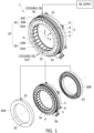
FIG. 1 is a schematic diagram illustrating a stator to which an oil circulation method is applied, in an oil circulation type motor In accordance with various exemplary embodiments of the present invention. -
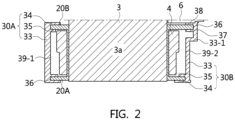
FIG. 2 is a cross-sectional view illustrating that an oil circulation structure applied to the stator in accordance with the exemplary embodiment of the present invention is sealed by a bobbin and a cooling chamber. -
FIG. 3 illustrates a non claimed example in which a bobbin cover of a cooling case for the sealed oil circulation structure is connected through a clip connection structure modified from an insertion connection structure. -
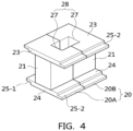
FIG. 4 illustrates internal and external bobbins forming the bobbin in accordance with a non claimed example. -
FIG. 5 illustrates a butt connection structure of the bobbin for the sealed oil circulation structure in accordance with a non claimed example. -
FIG. 6 illustrates a wedge connection structure, a round connection structure and an insertion connection structure for the bobbin in accordance with a non claimed example. -
FIG. 7 illustrates a non claimed eco vehicle to which the oil circulation type motor is applied. -
FIG. 8 illustrates an operation state that the motor in accordance with the present invention cools a coil through an oil circulation method. -
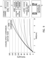
FIG. 9 is a cooling performance comparison graph showing a cooling effect of the oil circulation method in accordance with the present invention, compared to the prior art. - It may be understood that the appended drawings are not necessarily to scale, presenting a somewhat simplified representation of various features illustrative of the basic principles of the invention. The specific design features of the present invention as disclosed herein, including, for example, specific dimensions, orientations, locations, and shapes will be determined in part by the particularly intended application and use environment.
- In the figures, reference numbers refer to the same or equivalent parts of the present invention throughout the several figures of the drawing.
- Referring to
FIG. 1 , amotor 1 includes astator 2 to which power is applied and anoil circulating device 10, and performs a cooling operation on thestator 2 through an oil circulation type cooling structure. - The
stator 2 includes astator core 3, astator coil 4, asupport ring 5 and aterminal holder 6. Thestator core 3 has teeth 3a disposed at even intervals in a radial shape, thestator coil 4 is wound around each of the teeth 3a such that a current flows therethrough, thesupport ring 5 is coupled to thestator core 3 while surrounding thestator core 3, and theterminal holder 6 is coupled to the rear of thesupport ring 5 to supply power to aterminal 6a. Therefore, thestator 2 is coupled to a rotor (refer toFIG. 7 ) in an internal space of thestator core 3. - The
oil circulating device 10 includes abobbin 20 having two pairs of internal andexternal bobbins cooling case 30 having front and rear bobbin covers 30A and 30B, and coolingoil circulation holes - One pair of internal and
external bobbins front bobbin cover 30A at the front of thestator coil 4, and the other pair of internal andexternal bobbins rear bobbin cover 30B at the rear of thestator coil 4. - The cooling oil circulation holes are divided into an
inlet hole 31 and anoutlet hole 32. Theinlet hole 31 is configured as an entrance through cooling oil is introduced into the one pair of internal andexternal bobbins front bobbin cover 30A, and theoutlet hole 32 is configured as an exit through which cooling oil is discharged from the front cooling oil filled space after passing through the other pair of internal andexternal bobbins rear bobbin cover 30B. Theinlet hole 31 is connected to thefront bobbin cover 30A through aninlet pipe 30C such that cooling oil can be directly or intensively supplied to the space around thestator 2 or the outside of themotor 1 through an oil pump (refer toFIG. 8 ) connected to theinlet pipe 30C. In the instant case, theoutlet hole 32 is formed in thefront bobbin cover 30A. However, thesame outlet hole 32 may also be formed in therear bobbin cover 30B. - As a result, the
oil circulating device 10 forms a cooling oil circulation flow which enters thestator core 3 from the top portion of thestator core 3, circulates through the front and rear portions of thestator core 3, collects at the bottom portion of thestator core 3 under the effect of the gravity, and then escapes to the outside of thestator core 3. While the cooling oil circulates, thestator coil 4 is cooled by the cooling oil. Theoil circulating device 10 brings the cooling oil in direct contact with thestator coil 4 through the oil circulation method in which the front and rear cooling oil filled spaces (that is, front and rear cooing oil chambers 39-1 and 39-2 ofFIG. 2 ) are formed at the front and rear of thestator 2 along the circumference of thestator 2. Therefore, theoil circulating device 10 overcomes the limitations of the oil spraying method having low cooling performance and the oil direct injection method of which the use is limited depending on a coil winding method. - Therefore, the
motor 1 can significantly increase cooling efficiency through theoil circulating device 10, and thus contribute to achieving an increase of capacity and an improvement of output density, which are required by a concentrated winding type motor configured for a TMED. -
FIG. 2 illustrates that the front and rear cooling oil filled spaces of theoil circulating device 10 are formed at the front and rear of thestator coil 4 wound around each of the teeth 3a of thestator core 3, and serve as the front and rear cooling oil chambers 39-1 and 39-2. - The one pair of internal and
external bobbins stator core 3 in the inward and outward direction at the front of thestator coil 4 such that thestator coil 4 forms a front exposed portion, and the other pair of internal andexternal bobbins stator core 3 in the inward and outward direction at the rear of thestator coil 4 such that thestator coil 4 forms a rear exposed portion. - The
front bobbin cover 30A is coupled to a front position of thestator coil 4 to cover the front exposed portion of thestator coil 4, and therear bobbin cover 30B is coupled to a rear position of thestator coil 4 to cover the rear exposed portion of thestator coil 4. - Therefore, the front bobbin cover 30A forms the front cooling oil chamber 39-1 covering the front side of the
stator coil 4 with the one pair of internal andexternal bobbins rear bobbin cover 30B forms the rear cooling oil chamber 39-2 covering the rear side of thestator coil 4 with the other pair of internal andexternal bobbins stator coil 4 is submerged under cooling oil, and comes in direct contact with the cooling oil. - The
front bobbin cover 30A and theexternal bobbin 20B are fixed to each other through insertion connection, and therear bobbin cover 30B and theexternal bobbin 20B are also fixed to each other through insertion connection. - As a non claimed example, the
front bobbin cover 30A includes acase body 33 and acase fixing groove 36. Thecase body 33 covers thestator coil 4 to form the front cooling oil chamber 39-1, and thecase fixing groove 36 is formed by external andinternal flanges case body 33 with a space provided therebetween, such that theexternal bobbin 20B is inserted and fixed to thecase fixing groove 36. Therear bobbin cover 30B includes acase body 33, a case protrusion body 33-1, acase fixing groove 36, a fixingprotrusion 38 and anextended chamber 37. Thecase body 33 covers thestator coil 4 to form the rear cooling oil chamber 39-2, the case protrusion body 33-1 protrudes from thecase body 33, thecase fixing groove 36 is formed by external andinternal flanges case body 33 and the case protrusion body 33-1 with a space provided therebetween, such that theinternal bobbin 20A is inserted and fixed to thecase fixing groove 36, the fixingprotrusion 38 protrudes from the case protrusion body 33-1 and is inserted into a groove of theterminal holder 6 to strengthen a fixing force, and theextended chamber 37 is formed under thecase fixing groove 36 in the case protrusion body 33-1, forming a cooling oil filled space. -
FIG. 3 illustrates a non claimed clip connection structure between thefront bobbin cover 30A and theexternal bobbin 20B, as a modification of the insertion connection structure ofFIG. 2 . - As illustrated in
FIG. 3 , a clip groove 34-1 is formed in theexternal flange 34 of thefront bobbin cover 30A, and aclip protrusion 29 having a right-angled triangle cross-sectional shape protrudes from theexternal bobbin 20B. Therefore, when theexternal bobbin 20B and thefront bobbin cover 30A are coupled to each other, theexternal bobbin 20B is inserted into thecase fixing groove 36 between theexternal flange 34 and theinternal flange 35, and theclip protrusion 29 is coupled to the clip groove 34-1. Thus, a clip fixing force as well as the insertion fixing force is formed to further strengthen the fixed state. -
FIG. 4 illustrates the structures of the internal andexternal bobbins bobbin 20. As illustrated inFIG. 4 , non claimed examples of each of the internal andexternal bobbins bobbin body 21, upper andlower bobbin flanges coil seating surface 27, acoil chamber 28 and theclip protrusion 29. - As a non claimed example, the
bobbin body 21 is coupled in the lateral direction of one tooth 3a to be positioned at thestator coil 4 wound around the tooth 3a in the internal space of thestator core 3. Theupper bobbin flange 23 is formed at the top portion of thebobbin body 21 and has a larger length than the width of thebobbin body 21, and thelower bobbin flange 24 is formed at the bottom portion of thebobbin body 21 and has the same length as theupper bobbin flange 23. The top portion of thebobbin body 21 is defined as facing the front of thestator coil 4, and the bottom portion of thebobbin body 21 is defined as facing the rear of thestator coil 4. - As a non claimed example, the
coil seating surface 27 is formed as a groove in thebobbin body 21 and the upper andlower bobbin flanges coil chamber 28 is formed by thebobbin body 21 of theinternal bobbin 20A and thebobbin body 21 of theexternal bobbin 20B, which are brought in contact with each other, such that thecoil seating surface 27 of theinternal bobbin 20A and thecoil seating surface 27 of theexternal bobbin 20B cover thestator coil 4 wound around one tooth 3A inside and outside. Therefore, the top portion of thecoil chamber 28 is defined as facing the front of thestator coil 4, and the bottom portion of thecoil chamber 28 is defined as facing the rear of thestator coil 4. -
FIG. 5 and FIG. 6 illustrate non claimed examples of internal andexternal bobbin elements 20A-1 to 20An and 20B-1 to 20B-n which form a circular shape when the internal andexternal bobbins stator coil 4 wound around each of the teeth 3a of thestator core 3 are completely disposed. Here, n is an integer equal to or greater than 2.FIG. 5 and FIG. 6 illustrate that the arrangement of the internal andexternal bobbin elements 20A-1 to 20A-n and 20B-1 to 20B-n is achieved through a butt connection method, a wedge connection method, a round connection method and an insertion connection method. -
FIG. 5 illustrates the butt connection method which achieves the arrangement through connections between left and right butt end portions 25-1 and 25-2 of the internal andexternal bobbin elements 20A-1 to 20A-n and 20B-1 to 20B-n. As illustrated inFIG. 5 , each of the upper andlower bobbin flanges external bobbin elements 20A-1 to 20A-n and 20B-1 to 20B-n has a left butt end portion 25-1 formed as one end portion and a right butt end portion 25-2 formed as the other end portion. For example, when the left butt end portion 25-1 has an inversed L-shaped cross-section, the right butt end portion 25-2 has an L-shaped cross-section. - Therefore, when the internal and
external bobbin elements 20A-1 to 20A-n and 20B-1 to 20B-n are successively disposed, the left and right butt end portions 25-1 and 25-2 of the first internal andexternal bobbin elements 20A-1 and 20B-1, the second internal andexternal bobbin elements 20A-2 and 20B-2 and the nth internal andexternal bobbin elements 20A-n and 20B-n are coupled to each other through the L-shaped and inversed L-shaped cross-sectional structures. As a result, bobbin gaps formed by the connections between therespective bobbin bodies 21 forming the internal andexternal bobbin elements 20A-1 to 20A-n and 20B-1 to 20B-n are blocked by the arrangement structure constructed through the butt connection method using the left and right butt end portions 25-1 and 25-2. Thus, cooling oil stored in the front and rear cooling oil filled chambers 39-1 and 39-2 does not leak through the bobbin gaps. -
FIG. 6 illustrates that the upper andlower bobbin flanges external bobbin elements 20A-1 to 20A-n and 20B-1 to 20B-n have left and right wedge end portions 25-3 and 25-4, left and right round end portions 25-5 and 25-6 or left and right insertion end portions 25-7 and 25-8. As illustrated inFIG. 6 , when the left wedge end portion 25-3 of the left and right wedge end portions 25-3 and 25-4 has a wedge groove-shaped cross-section, the right wedge end portion 25-4 has a wedge protrusion-shaped cross-section. Furthermore, when the left round end portion 25-5 of the left and right round end portions 25-5 and 25-6 has a hemispherical groove-shaped cross-section, the right round end portion 25-6 has a hemispherical protrusion-shaped cross-section. Furthermore, when the left insertion end portion 25-7 of the left and right insertion end portions 25-7 and 25-8 has a linear groove-shaped cross-section, the right insertion end portion 25-8 has a linear protrusion-shaped cross-section. - Therefore, each of the wedge groove/wedge protrusion-shaped cross-sectional structure, the hemispherical groove/hemispherical protrusion-shaped cross-sectional structure and the linear groove/linear protrusion-shaped cross-sectional structure can also block the bobbin gaps formed through the connections between the
respective bobbin bodies 21 forming the internal andexternal bobbin elements 20A-1 to 20A-n and 20B-1 to 20B-n. Thus, cooling oil stored in the front and rear cooling oil chambers 39-1 and 39-2 does not escape through the bobbin gaps. -
FIG. 7 illustrates a non claimed example in which themotor 1 including theoil circulating device 10 is applied as a driving motor of avehicle 100. In the instant case, an eco vehicle is applied as thevehicle 100.FIG. 8 illustrates the cooling of the motor according toclaim 1. - Referring to
FIG. 7 , thevehicle 100 includes themotor 1 and an oil pump 100-1. - The oil pump 100-1 pumps auto transmission fluid supplied to a transmission and circulates the auto transmission fluid as cooling oil through the
motor 1, or pumps cooling oil stored in themotor 1 and circulates the cooling oil through themotor 1. - The
motor 1 may include cooling oil stored therein, or receive auto transmission fluid as cooling oil. Themotor 1 includes astator 2, arotor 7 and arotation shaft 8 which are embedded in a motor housing 1-1 which is to be mounted in thevehicle 100. Themotor 1 may be connected to an engine clutch. For example, a current is supplied to thestator 2, therotor 7 is rotated by the current supplied to thestator 2, and therotation shaft 8 is rotated with therotor 7 and outputs a motor torque. - The
stator 2 includes thestator core 3, thestator coil 4, thesupport ring 5 and theterminal holder 6, which are described with reference toFIGS. 1 to 6 , and theoil circulating device 10 is applied to thestator 2. Therefore, themotor 1 cools thestator coil 4 through the oil circulation method using theoil circulating device 10. -
FIGS. 2 and8 illustrate the operation state that theoil circulating device 10 cools thestator coil 4 through the oil circulation method during the operation of themotor 1. - As illustrated in
FIGS. 2 and8 , the front cooling oil chamber 39-1 is formed by thefront bobbin cover 30A and the one pair of internal andexternal bobbins stator coil 4, and the rear cooling oil chamber 39-2 is formed by therear bobbin cover 30B and the other pair of internal andexternal bobbins stator coil 4. - As such, when operation oil (transmission) or cooling oil is pumped inside or outside the
motor 1 by the oil pump 100-1, the cooling oil is introduced into the front cooling oil chamber 39-1 through theinlet hole 31 to which theinlet pipe 30C is connected. As such, the cooling oil flows into the rear cooling oil chamber 39-2 while filling the front cooling oil chamber 39-1. Thus, the front and rear cooling oil chambers 39-1 and 39-2 are filled with the cooling oil through the flow of cooling oil. Therefore, thestator coil 4 surrounded by the front and rear cooling oil chambers 39-1 and 39-2 comes in direct contact with the cooling oil. - As such, when the front and rear cooling oil chambers 39-1 and 39-2 are filled with the cooling oil such that the
stator coil 4 is submerged under the cooling oil, the cooling oil collects in theoutlet hole 32 located under thestator core 3 under the effect of the gravity. The cooling oil escapes from thestator core 3 through theoutlet hole 32, fills the internal to themotor 1, and is then circulated through themotor 1 by a pumping operation of the oil pump 100-1. In the instant case, when theoutlet hole 32 is also formed in therear bobbin cover 30B, the cooling oil may be discharged through the rear cooling oil chamber 39-2. - Therefore, according to the oil circulation method of the
oil circulating device 10, a cooling oil circulation flow may occur regardless of the rotation of themotor 1, while thestator coil 4 is always submerged under the cooling oil. Thus, the oil circulation method can maintain high cooling performance even when the motor is stopped or under a vehicle condition including a gradient standstill or low-speed climbing condition in which the motor is driven at low speed and high power is required. -
FIG. 9 is a cooling performance comparison graph showing a cooling effect of the oil circulation method E of theoil circulating device 10 for themotor 1, compared to those of an oil cooling jacket method B, an oil spraying method C and an oil direct injection method D. - The time-temperature graph of
FIG. 9 shows the motor cooling efficiencies of the respective methods; compared to a state in which cooling is not performed (referred to as non-cooling state). Among them, the oil circulation method E has the highest motor cooling efficiency, and the motor cooling efficiency decreases in order of the oil direct injection method D, the oil spraying method C and the oil cooling jacket method B. - The oil circulation method E having high motor cooling efficiency may be effectively applied to the concentrated winding type motor in which the moving direction of oil scattered from the
rotor 7 is inevitably blocked by thebobbins stator coil 4 is separately disposed for each tooth 3a of thestator core 3. Therefore, the concentrated winding type motor to which the oil circulation method E is applied can significantly reduce a lot of efforts required for controlling the temperature of a drive motor of an eco vehicle. - As described above, the oil circulation type motor according to the present invention includes the cooling oil chambers 39-1 and 39-2 through which cooling oil pumped by the oil pump 100-1 is introduced and discharged, the cooling oil chambers 39-1 and 39-2 being formed along the circumference of the
stator core 3. Furthermore, the oil circulation type motor includes theoil circulating device 10 which allows the cooling oil to enter the cooling oil chambers 39-1 and 39-2, wet thestator coil 4 wound around thestator core 3, and escape from the cooling oil chambers 39-1 and 39-2. Therefore, since the oil circulation type motor can exhibit higher cooling efficiency than the oil cooling jacket method, the oil spraying method and the oil direct injection method, the capacity can be improved while the output density is improved. The oil circulation method of theoil circulating device 10 can be effectively applied to a concentrated winding type motor configured for a TMED. - In accordance with the present invention, the oil circulation type motor may achieve the following effects.
- First, the oil circulation type motor can exhibit a motor cooling effect which is twice or more higher than the oil spraying method or the oil direct injection method. Second, since the whole coils of the motor is completely surrounded by the cooling channels (or cooling chambers), the whole coils can be uniformly cooled, compared to the oil direct injection method or a method for partially submerging a coil under oil. Third, a reduction of the cooling performance does not occur even when the motor is not rotated, unlike the oil spraying method. Fourth, a simple cover structure for the bobbins and the terminal holder is applied to form the cooling chambers (or cooling channels) including the coil. Thus, the cooling structure can be constructed at lower cost than the oil spraying method or the oil direct injection method which is an indirect cooling method. Fifth, oil introduced into the upper oil hole is automatically discharged through the lower oil hole under the effect of the gravity. Thus, since the oil circulation type motor utilizes a smaller oil pressure than the oil direct injection method requiring a high oil pressure, the capacity of the oil pump can be minimized, and the manufacturing cost can be reduced. Sixth, since the oil circulation type motor has higher cooling efficiency than the oil spraying method and the oil direct injection method, the oil circulation type motor can be applied to a concentrated winding type motor which requires an increase of capacity and an improvement of output density to be applied to a TMED.
- For convenience in explanation and accurate definition in the appended claims, the terms "upper", "lower", "internal", "outer", "up", "down", "upper", "lower", "upwards", "downwards", "front", "rear", "back", "inside", "outside", "inwardly", "outwardly", "internal", "external", "internal", "outer", "forwards", and "backwards" are used to describe features of the exemplary embodiments with reference to the positions of such features as displayed in the figures.
- The foregoing descriptions of specific exemplary embodiments of the present invention have been presented for purposes of illustration and description. The present invention is only defined by the appended set of claims.
Claims (2)
- A concentrated winding type motor comprisinga stator comprising a stator core (3),the stator core (3) comprising teeth (3a) disposed at even intervals in a radial shape, so as to define an internal space for a rotor,wherein a bobbin (20) covers each of the teeth (3a) of the stator core (3),wherein a stator coil (4) is wound around the bobbin (20) of each of the teeth (3a) of the stator core (3),each bobbin (20) comprising two pairs of internal and external bobbin portions (20A, 20B),wherein the first pair of internal and external bobbin portions (20A, 20B) is located on a first axial side of the bobbin (20),and wherein one bobbin portion (20A) has the shape of a radially internal flange (20A) that extends axially away from the tooth (3a), and the other bobbin portion (20B) has the shape of a radially external flange (20B) that extends axially away from the tooth (3a), such that the stator coil (4) forms a front exposed portion between the first pair of internal and external bobbin portions (20A, 20B)wherein the second pair of internal and external bobbin portions (20A, 20B) is located on a second axial side of the bobbin (20),and wherein one bobbin portion (20A) has the shape of a radially internal flange (20A) that extends axially away from the tooth (3a), and the other bobbin portion (20B) has the shape of a radially external flange (20B) that extends axially away from the tooth (3a), such that the stator coil (4) forms a rear exposed portion between the second pair of internal and external bobbin portions (20A, 20B),the motor further comprising a cooling oil circulating device (10),wherein the cooling oil circulating device (10) comprisesa front cooling oil chamber (39-1), a rear cooling oil chamber (39-2), and cooling oil circulation inlet hole (31) and outlet hole (32),wherein the front cooling oil chamber (39-1) and the rear cooling oil chamber (39-2) are formed along a circumference of the stator core (3)at a first axial side and at a second axial side of the stator core (3) respectively,wherein the front cooling oil chamber (39-1) is formed bythe first pair of internal and external bobbin portions (20A, 20B) of each tooth (3a),respectively forming radially internal and radially external walls of the front cooling oil chamber (39-1),the front exposed portion of the stator coil (4),and a front bobbin cover (30A) fixed to the bobbin portions (20A, 20B),wherein the rear cooling oil chamber (39-2) is formed bythe second pair of internal and external bobbin portions (20A, 20B) of each tooth (3a),respectively forming the radially internal and radially external walls of the rear cooling oil chamber (39-2),the rear exposed portion of the stator coil (4),and a rear bobbin cover (30B) fixed to the bobbin portions (20A, 20B),wherein the cooling oil chambers (39-1, 39-2) are fluidically-communicating with each other,whereinthe inlet hole (31) is located at a top portion of the stator core (3), on the front bobbin cover (30A) and is configured as an entrance through which cooling oil is introduced into the front cooling oil chamber (39-1) via an inlet pipe (30C) connected thereto andthe outlet hole (32) is located at the bottom of the stator core (3) on the front bobbin cover (30A) and/or in in the rear bobbin cover (30B) and is configured as an exit through which cooling oil is discharged,
so thatthe cooling oil is introduced into the front cooling oil chamber (39-1) through the inlet hole (31), flows into the rear cooling oil chamber (39-2) while filling the front cooling oil chamber (39-1), wets the stator coil (4) wound around each of the stator core teeth (3a), andis discharged from the cooling oil chambers (39-1, 39-2) under the effect of the gravity through the outlet hole (32). - The motor of claim 1, wherein the inlet hole (31) is connected to an inlet pipe (30C), and the inlet pipe (30C) supplies the cooling oil to a space around the stator core (3).
Applications Claiming Priority (1)
| Application Number | Priority Date | Filing Date | Title |
|---|---|---|---|
| KR1020170123929A KR102452689B1 (en) | 2017-09-26 | 2017-09-26 | Oil Coil Circulation type Drive Motor and Echo Vehicle thereby |
Publications (2)
| Publication Number | Publication Date |
|---|---|
| EP3460958A1 EP3460958A1 (en) | 2019-03-27 |
| EP3460958B1 true EP3460958B1 (en) | 2023-11-15 |
Family
ID=61691752
Family Applications (1)
| Application Number | Title | Priority Date | Filing Date |
|---|---|---|---|
| EP18162520.3A Active EP3460958B1 (en) | 2017-09-26 | 2018-03-19 | Oil circulation type motor and eco vehicle including the same |
Country Status (4)
| Country | Link |
|---|---|
| US (1) | US10756599B2 (en) |
| EP (1) | EP3460958B1 (en) |
| KR (1) | KR102452689B1 (en) |
| CN (1) | CN109560628B (en) |
Families Citing this family (22)
| Publication number | Priority date | Publication date | Assignee | Title |
|---|---|---|---|---|
| KR102452689B1 (en) * | 2017-09-26 | 2022-10-11 | 현대자동차주식회사 | Oil Coil Circulation type Drive Motor and Echo Vehicle thereby |
| KR102635370B1 (en) * | 2019-01-08 | 2024-02-08 | 엘지이노텍 주식회사 | Motor |
| JP6957552B2 (en) * | 2019-04-23 | 2021-11-02 | 本田技研工業株式会社 | Rotating machine |
| US11469647B2 (en) * | 2019-06-07 | 2022-10-11 | Borgwarner Inc. | Oil cooling system for a stator of an electric machine |
| KR102788638B1 (en) * | 2019-10-16 | 2025-04-01 | 현대모비스 주식회사 | Improved core bobbin assembly and motor cooling method using the same |
| US12592606B2 (en) | 2019-11-06 | 2026-03-31 | Eaton Intelligent Power Limited | Axial flux motor with air cooling system |
| US12266985B2 (en) | 2019-12-10 | 2025-04-01 | Eaton Intelligent Power Limited | Axial flux motor with cooling jacket |
| KR102896998B1 (en) * | 2020-01-06 | 2025-12-08 | 엘지이노텍 주식회사 | Motor and manufacturing method of stator included therein |
| US12424897B2 (en) | 2020-02-21 | 2025-09-23 | Eaton Intelligent Power Limited | Electric motor with integrated cooling system |
| DE102020203416A1 (en) | 2020-03-17 | 2021-09-23 | Brose Fahrzeugteile SE & Co. Kommanditgesellschaft, Würzburg | Electric motor stator and electric motor |
| KR102791571B1 (en) * | 2020-06-22 | 2025-04-03 | 현대자동차주식회사 | Stator for driving motor |
| KR102817539B1 (en) | 2020-08-18 | 2025-06-05 | 현대자동차주식회사 | Driving motor for automobile |
| CN114552815B (en) * | 2020-11-26 | 2025-05-02 | 通用汽车环球科技运作有限责任公司 | Direct contact cooling of axial flux motor stators |
| KR102594648B1 (en) * | 2021-03-17 | 2023-10-27 | 한국전자기술연구원 | Rotor bobbin for field winding motor and rotor comprising the same |
| KR102626190B1 (en) * | 2021-11-19 | 2024-01-18 | 엘지전자 주식회사 | Electric motor |
| EP4187758B1 (en) * | 2021-11-29 | 2026-04-29 | Hamilton Sundstrand Corporation | Stator for electrical machines |
| CN115242004A (en) * | 2022-08-05 | 2022-10-25 | 小米汽车科技有限公司 | Stator, motor and vehicle |
| CN115603484B (en) * | 2022-10-21 | 2026-04-24 | 上海盘毂动力科技股份有限公司 | An axial magnetic field motor and its stator cooling structure |
| WO2024230883A1 (en) * | 2023-05-05 | 2024-11-14 | Schaeffler Technologies AG & Co. KG | Stator, electrical machine and drivetrain |
| JP7637271B1 (en) | 2024-01-16 | 2025-02-27 | 富田電機股▲ふん▼有限公司 | Motor stator cooling structure |
| JP2025147902A (en) * | 2024-03-25 | 2025-10-07 | 株式会社アイシン | rotating electrical machines |
| GB2642037A (en) * | 2024-06-19 | 2025-12-31 | Jaguar Land Rover Ltd | Clip-on annular component |
Citations (3)
| Publication number | Priority date | Publication date | Assignee | Title |
|---|---|---|---|---|
| EP1215800A2 (en) * | 2000-12-14 | 2002-06-19 | Nissan Motor Co., Ltd. | Cooling passage in the slots of a rotating electric machine |
| US20030057797A1 (en) * | 2001-09-26 | 2003-03-27 | Nissan Motor Co., Ltd. | Stator structure for rotary electric machine |
| US20110215660A1 (en) * | 2008-11-21 | 2011-09-08 | Toyota Jidosha Kabushiki Kaisha | Rotating electrical machine |
Family Cites Families (23)
| Publication number | Priority date | Publication date | Assignee | Title |
|---|---|---|---|---|
| JP3661529B2 (en) * | 1999-11-17 | 2005-06-15 | 日産自動車株式会社 | Motor cooling device |
| JP3623471B2 (en) * | 2001-09-03 | 2005-02-23 | 本田技研工業株式会社 | Stator |
| JP2003143810A (en) * | 2001-11-02 | 2003-05-16 | Toyota Motor Corp | Segment coil motor |
| JP4026496B2 (en) * | 2002-12-26 | 2007-12-26 | 日産自動車株式会社 | Cooling structure of rotating electric machine |
| JP5021443B2 (en) | 2007-12-14 | 2012-09-05 | 日立オートモティブシステムズ株式会社 | Rotating electric machine |
| JP5386263B2 (en) * | 2009-07-30 | 2014-01-15 | 日立オートモティブシステムズ株式会社 | Rotating electric machine |
| JP4716060B2 (en) * | 2009-11-30 | 2011-07-06 | 株式会社富士通ゼネラル | Axial gap type electric motor and pump device |
| CN102097910A (en) * | 2011-03-22 | 2011-06-15 | 北京理工大学 | In-stator slot oil cooled high power density permanent magnet synchronous motor |
| KR101398458B1 (en) | 2011-05-16 | 2014-05-30 | 엘지전자 주식회사 | Electric motor and electric vehicle having the same |
| JP5957803B2 (en) * | 2011-05-17 | 2016-07-27 | アイシン精機株式会社 | Rotating electric machine |
| DE112012006066T5 (en) * | 2012-03-22 | 2014-12-04 | Mitsubishi Electric Corporation | Anchor for a rotating electrical machine |
| FR2995738B1 (en) * | 2012-09-19 | 2016-01-01 | Valeo Equip Electr Moteur | STATOR FOR ROTATING ELECTRIC MACHINE WITH COOLING CIRCUIT AND CORRESPONDING ROTATING ELECTRIC MACHINE |
| JP2014087248A (en) * | 2012-10-26 | 2014-05-12 | Toshiba Corp | Liquid cooled type rotary electric machine and rotary electric machine system |
| KR101405225B1 (en) * | 2012-12-12 | 2014-06-10 | 현대자동차 주식회사 | Bobin and rotor of wound rotor synchronous motor using this |
| DE102015100090A1 (en) * | 2014-01-17 | 2015-07-23 | Ecomotors, Inc. | Cooling of stator coils of an electrical machine |
| GB2525157B (en) * | 2014-02-18 | 2016-08-24 | Yasa Motors Ltd | Machine cooling systems |
| CN203813543U (en) * | 2014-05-09 | 2014-09-03 | 珠海格力节能环保制冷技术研究中心有限公司 | Motor insulation framework and motor provided with same |
| US10404139B2 (en) | 2014-05-27 | 2019-09-03 | Mitsubishi Electric Corporation | Rotary electric machine |
| KR20160023314A (en) | 2014-08-22 | 2016-03-03 | 현대모비스 주식회사 | Motor having housing with contact type cooling channel structure and Method for manufacturing the same |
| JP5955437B1 (en) | 2015-04-27 | 2016-07-20 | 三菱電機株式会社 | Rotating electric machine |
| JP6672638B2 (en) | 2015-08-24 | 2020-03-25 | スズキ株式会社 | motor |
| JP6072866B1 (en) * | 2015-08-26 | 2017-02-01 | 三菱電機株式会社 | Rotating electric machine |
| KR102452689B1 (en) * | 2017-09-26 | 2022-10-11 | 현대자동차주식회사 | Oil Coil Circulation type Drive Motor and Echo Vehicle thereby |
-
2017
- 2017-09-26 KR KR1020170123929A patent/KR102452689B1/en active Active
- 2017-12-12 US US15/839,471 patent/US10756599B2/en active Active
-
2018
- 2018-03-19 EP EP18162520.3A patent/EP3460958B1/en active Active
- 2018-03-26 CN CN201810251201.7A patent/CN109560628B/en active Active
Patent Citations (3)
| Publication number | Priority date | Publication date | Assignee | Title |
|---|---|---|---|---|
| EP1215800A2 (en) * | 2000-12-14 | 2002-06-19 | Nissan Motor Co., Ltd. | Cooling passage in the slots of a rotating electric machine |
| US20030057797A1 (en) * | 2001-09-26 | 2003-03-27 | Nissan Motor Co., Ltd. | Stator structure for rotary electric machine |
| US20110215660A1 (en) * | 2008-11-21 | 2011-09-08 | Toyota Jidosha Kabushiki Kaisha | Rotating electrical machine |
Also Published As
| Publication number | Publication date |
|---|---|
| KR20190035095A (en) | 2019-04-03 |
| US20190097499A1 (en) | 2019-03-28 |
| CN109560628A (en) | 2019-04-02 |
| EP3460958A1 (en) | 2019-03-27 |
| KR102452689B1 (en) | 2022-10-11 |
| CN109560628B (en) | 2022-04-05 |
| US10756599B2 (en) | 2020-08-25 |
Similar Documents
| Publication | Publication Date | Title |
|---|---|---|
| US10756599B2 (en) | Oil circulation type motor and echo vehicle including the same | |
| US6617716B2 (en) | Rotary electric machine having stator coolant passage means | |
| US8242645B2 (en) | Rotating electric machine enabling cooling of a cooling target region | |
| US10532650B2 (en) | Drive motor cooled by heat exchange with coolant and eco-friendly vehicle using the same | |
| US8446056B2 (en) | Electric machine cooling system and method | |
| JP5075872B2 (en) | Electric motor | |
| US8508085B2 (en) | Internal cooling of stator assembly in an electric machine | |
| JP3967624B2 (en) | Electric motor | |
| US9755482B2 (en) | Electric machine with liquid cooling and method of assembling | |
| JP5656556B2 (en) | Rotating electric machine | |
| JP5075874B2 (en) | Electric motor | |
| US20130043747A1 (en) | Electric Machine Cooling | |
| KR20130032828A (en) | Electric machine module cooling system and method | |
| KR20140008518A (en) | Electric machine cooling system and method | |
| ES2673423T3 (en) | Liquid cooling procedure and device of an electric motor and transmission configuration | |
| CN108702040A (en) | Electric rotating machine with improved cooling | |
| JP2013090391A (en) | Rotary electric machine | |
| US20200280244A1 (en) | Electric machine with internal cooling passageways | |
| US20240313600A1 (en) | Electric machine, component for an electric machine, and motor vehicle with an electric machine | |
| US20070013259A1 (en) | Rotary electric machine with stator outer surface designed to enhance heat dissipation | |
| US12451764B2 (en) | Motor having cooling flow path | |
| AU2014322794B2 (en) | An electric or hybrid vehicle using motor-generator having shaft with centrifugal fan blades for cooling | |
| CN107949978B (en) | Rotary electric machines with optimized cooling | |
| JP2024534284A (en) | Heat exchanger system for electric motors | |
| US20250211045A1 (en) | Wound field motor |
Legal Events
| Date | Code | Title | Description |
|---|---|---|---|
| PUAI | Public reference made under article 153(3) epc to a published international application that has entered the european phase |
Free format text: ORIGINAL CODE: 0009012 |
|
| STAA | Information on the status of an ep patent application or granted ep patent |
Free format text: STATUS: THE APPLICATION HAS BEEN PUBLISHED |
|
| AK | Designated contracting states |
Kind code of ref document: A1 Designated state(s): AL AT BE BG CH CY CZ DE DK EE ES FI FR GB GR HR HU IE IS IT LI LT LU LV MC MK MT NL NO PL PT RO RS SE SI SK SM TR |
|
| AX | Request for extension of the european patent |
Extension state: BA ME |
|
| STAA | Information on the status of an ep patent application or granted ep patent |
Free format text: STATUS: REQUEST FOR EXAMINATION WAS MADE |
|
| 17P | Request for examination filed |
Effective date: 20190403 |
|
| RBV | Designated contracting states (corrected) |
Designated state(s): AL AT BE BG CH CY CZ DE DK EE ES FI FR GB GR HR HU IE IS IT LI LT LU LV MC MK MT NL NO PL PT RO RS SE SI SK SM TR |
|
| STAA | Information on the status of an ep patent application or granted ep patent |
Free format text: STATUS: EXAMINATION IS IN PROGRESS |
|
| 17Q | First examination report despatched |
Effective date: 20191205 |
|
| RAP3 | Party data changed (applicant data changed or rights of an application transferred) |
Owner name: HYUNDAI MOTOR COMPANY Owner name: KIA CORPORATION |
|
| RIC1 | Information provided on ipc code assigned before grant |
Ipc: H02K 9/197 20060101ALI20230426BHEP Ipc: H02K 5/20 20060101ALI20230426BHEP Ipc: H02K 7/00 20060101ALI20230426BHEP Ipc: H02K 3/32 20060101ALI20230426BHEP Ipc: H02K 3/24 20060101AFI20230426BHEP |
|
| GRAP | Despatch of communication of intention to grant a patent |
Free format text: ORIGINAL CODE: EPIDOSNIGR1 |
|
| STAA | Information on the status of an ep patent application or granted ep patent |
Free format text: STATUS: GRANT OF PATENT IS INTENDED |
|
| P01 | Opt-out of the competence of the unified patent court (upc) registered |
Effective date: 20230428 |
|
| INTG | Intention to grant announced |
Effective date: 20230609 |
|
| GRAS | Grant fee paid |
Free format text: ORIGINAL CODE: EPIDOSNIGR3 |
|
| GRAA | (expected) grant |
Free format text: ORIGINAL CODE: 0009210 |
|
| STAA | Information on the status of an ep patent application or granted ep patent |
Free format text: STATUS: THE PATENT HAS BEEN GRANTED |
|
| AK | Designated contracting states |
Kind code of ref document: B1 Designated state(s): AL AT BE BG CH CY CZ DE DK EE ES FI FR GB GR HR HU IE IS IT LI LT LU LV MC MK MT NL NO PL PT RO RS SE SI SK SM TR |
|
| REG | Reference to a national code |
Ref country code: CH Ref legal event code: EP Ref country code: GB Ref legal event code: FG4D |
|
| REG | Reference to a national code |
Ref country code: DE Ref legal event code: R096 Ref document number: 602018061045 Country of ref document: DE |
|
| REG | Reference to a national code |
Ref country code: IE Ref legal event code: FG4D |
|
| REG | Reference to a national code |
Ref country code: LT Ref legal event code: MG9D |
|
| REG | Reference to a national code |
Ref country code: NL Ref legal event code: MP Effective date: 20231115 |
|
| PG25 | Lapsed in a contracting state [announced via postgrant information from national office to epo] |
Ref country code: GR Free format text: LAPSE BECAUSE OF FAILURE TO SUBMIT A TRANSLATION OF THE DESCRIPTION OR TO PAY THE FEE WITHIN THE PRESCRIBED TIME-LIMIT Effective date: 20240216 |
|
| PG25 | Lapsed in a contracting state [announced via postgrant information from national office to epo] |
Ref country code: IS Free format text: LAPSE BECAUSE OF FAILURE TO SUBMIT A TRANSLATION OF THE DESCRIPTION OR TO PAY THE FEE WITHIN THE PRESCRIBED TIME-LIMIT Effective date: 20240315 |
|
| PG25 | Lapsed in a contracting state [announced via postgrant information from national office to epo] |
Ref country code: LT Free format text: LAPSE BECAUSE OF FAILURE TO SUBMIT A TRANSLATION OF THE DESCRIPTION OR TO PAY THE FEE WITHIN THE PRESCRIBED TIME-LIMIT Effective date: 20231115 |
|
| REG | Reference to a national code |
Ref country code: AT Ref legal event code: MK05 Ref document number: 1632669 Country of ref document: AT Kind code of ref document: T Effective date: 20231115 |
|
| PG25 | Lapsed in a contracting state [announced via postgrant information from national office to epo] |
Ref country code: NL Free format text: LAPSE BECAUSE OF FAILURE TO SUBMIT A TRANSLATION OF THE DESCRIPTION OR TO PAY THE FEE WITHIN THE PRESCRIBED TIME-LIMIT Effective date: 20231115 |
|
| PG25 | Lapsed in a contracting state [announced via postgrant information from national office to epo] |
Ref country code: AT Free format text: LAPSE BECAUSE OF FAILURE TO SUBMIT A TRANSLATION OF THE DESCRIPTION OR TO PAY THE FEE WITHIN THE PRESCRIBED TIME-LIMIT Effective date: 20231115 |
|
| PG25 | Lapsed in a contracting state [announced via postgrant information from national office to epo] |
Ref country code: ES Free format text: LAPSE BECAUSE OF FAILURE TO SUBMIT A TRANSLATION OF THE DESCRIPTION OR TO PAY THE FEE WITHIN THE PRESCRIBED TIME-LIMIT Effective date: 20231115 |
|
| PG25 | Lapsed in a contracting state [announced via postgrant information from national office to epo] |
Ref country code: NL Free format text: LAPSE BECAUSE OF FAILURE TO SUBMIT A TRANSLATION OF THE DESCRIPTION OR TO PAY THE FEE WITHIN THE PRESCRIBED TIME-LIMIT Effective date: 20231115 Ref country code: LT Free format text: LAPSE BECAUSE OF FAILURE TO SUBMIT A TRANSLATION OF THE DESCRIPTION OR TO PAY THE FEE WITHIN THE PRESCRIBED TIME-LIMIT Effective date: 20231115 Ref country code: IS Free format text: LAPSE BECAUSE OF FAILURE TO SUBMIT A TRANSLATION OF THE DESCRIPTION OR TO PAY THE FEE WITHIN THE PRESCRIBED TIME-LIMIT Effective date: 20240315 Ref country code: GR Free format text: LAPSE BECAUSE OF FAILURE TO SUBMIT A TRANSLATION OF THE DESCRIPTION OR TO PAY THE FEE WITHIN THE PRESCRIBED TIME-LIMIT Effective date: 20240216 Ref country code: ES Free format text: LAPSE BECAUSE OF FAILURE TO SUBMIT A TRANSLATION OF THE DESCRIPTION OR TO PAY THE FEE WITHIN THE PRESCRIBED TIME-LIMIT Effective date: 20231115 Ref country code: BG Free format text: LAPSE BECAUSE OF FAILURE TO SUBMIT A TRANSLATION OF THE DESCRIPTION OR TO PAY THE FEE WITHIN THE PRESCRIBED TIME-LIMIT Effective date: 20240215 Ref country code: AT Free format text: LAPSE BECAUSE OF FAILURE TO SUBMIT A TRANSLATION OF THE DESCRIPTION OR TO PAY THE FEE WITHIN THE PRESCRIBED TIME-LIMIT Effective date: 20231115 Ref country code: PT Free format text: LAPSE BECAUSE OF FAILURE TO SUBMIT A TRANSLATION OF THE DESCRIPTION OR TO PAY THE FEE WITHIN THE PRESCRIBED TIME-LIMIT Effective date: 20240315 |
|
| PG25 | Lapsed in a contracting state [announced via postgrant information from national office to epo] |
Ref country code: SE Free format text: LAPSE BECAUSE OF FAILURE TO SUBMIT A TRANSLATION OF THE DESCRIPTION OR TO PAY THE FEE WITHIN THE PRESCRIBED TIME-LIMIT Effective date: 20231115 Ref country code: RS Free format text: LAPSE BECAUSE OF FAILURE TO SUBMIT A TRANSLATION OF THE DESCRIPTION OR TO PAY THE FEE WITHIN THE PRESCRIBED TIME-LIMIT Effective date: 20231115 Ref country code: PL Free format text: LAPSE BECAUSE OF FAILURE TO SUBMIT A TRANSLATION OF THE DESCRIPTION OR TO PAY THE FEE WITHIN THE PRESCRIBED TIME-LIMIT Effective date: 20231115 Ref country code: NO Free format text: LAPSE BECAUSE OF FAILURE TO SUBMIT A TRANSLATION OF THE DESCRIPTION OR TO PAY THE FEE WITHIN THE PRESCRIBED TIME-LIMIT Effective date: 20240215 Ref country code: LV Free format text: LAPSE BECAUSE OF FAILURE TO SUBMIT A TRANSLATION OF THE DESCRIPTION OR TO PAY THE FEE WITHIN THE PRESCRIBED TIME-LIMIT Effective date: 20231115 Ref country code: HR Free format text: LAPSE BECAUSE OF FAILURE TO SUBMIT A TRANSLATION OF THE DESCRIPTION OR TO PAY THE FEE WITHIN THE PRESCRIBED TIME-LIMIT Effective date: 20231115 |
|
| PG25 | Lapsed in a contracting state [announced via postgrant information from national office to epo] |
Ref country code: DK Free format text: LAPSE BECAUSE OF FAILURE TO SUBMIT A TRANSLATION OF THE DESCRIPTION OR TO PAY THE FEE WITHIN THE PRESCRIBED TIME-LIMIT Effective date: 20231115 |
|
| PG25 | Lapsed in a contracting state [announced via postgrant information from national office to epo] |
Ref country code: CZ Free format text: LAPSE BECAUSE OF FAILURE TO SUBMIT A TRANSLATION OF THE DESCRIPTION OR TO PAY THE FEE WITHIN THE PRESCRIBED TIME-LIMIT Effective date: 20231115 |
|
| PG25 | Lapsed in a contracting state [announced via postgrant information from national office to epo] |
Ref country code: SK Free format text: LAPSE BECAUSE OF FAILURE TO SUBMIT A TRANSLATION OF THE DESCRIPTION OR TO PAY THE FEE WITHIN THE PRESCRIBED TIME-LIMIT Effective date: 20231115 |
|
| PG25 | Lapsed in a contracting state [announced via postgrant information from national office to epo] |
Ref country code: SM Free format text: LAPSE BECAUSE OF FAILURE TO SUBMIT A TRANSLATION OF THE DESCRIPTION OR TO PAY THE FEE WITHIN THE PRESCRIBED TIME-LIMIT Effective date: 20231115 Ref country code: SK Free format text: LAPSE BECAUSE OF FAILURE TO SUBMIT A TRANSLATION OF THE DESCRIPTION OR TO PAY THE FEE WITHIN THE PRESCRIBED TIME-LIMIT Effective date: 20231115 Ref country code: RO Free format text: LAPSE BECAUSE OF FAILURE TO SUBMIT A TRANSLATION OF THE DESCRIPTION OR TO PAY THE FEE WITHIN THE PRESCRIBED TIME-LIMIT Effective date: 20231115 Ref country code: IT Free format text: LAPSE BECAUSE OF FAILURE TO SUBMIT A TRANSLATION OF THE DESCRIPTION OR TO PAY THE FEE WITHIN THE PRESCRIBED TIME-LIMIT Effective date: 20231115 Ref country code: EE Free format text: LAPSE BECAUSE OF FAILURE TO SUBMIT A TRANSLATION OF THE DESCRIPTION OR TO PAY THE FEE WITHIN THE PRESCRIBED TIME-LIMIT Effective date: 20231115 Ref country code: DK Free format text: LAPSE BECAUSE OF FAILURE TO SUBMIT A TRANSLATION OF THE DESCRIPTION OR TO PAY THE FEE WITHIN THE PRESCRIBED TIME-LIMIT Effective date: 20231115 Ref country code: CZ Free format text: LAPSE BECAUSE OF FAILURE TO SUBMIT A TRANSLATION OF THE DESCRIPTION OR TO PAY THE FEE WITHIN THE PRESCRIBED TIME-LIMIT Effective date: 20231115 |
|
| REG | Reference to a national code |
Ref country code: DE Ref legal event code: R097 Ref document number: 602018061045 Country of ref document: DE |
|
| PLBE | No opposition filed within time limit |
Free format text: ORIGINAL CODE: 0009261 |
|
| STAA | Information on the status of an ep patent application or granted ep patent |
Free format text: STATUS: NO OPPOSITION FILED WITHIN TIME LIMIT |
|
| 26N | No opposition filed |
Effective date: 20240819 |
|
| PG25 | Lapsed in a contracting state [announced via postgrant information from national office to epo] |
Ref country code: SI Free format text: LAPSE BECAUSE OF FAILURE TO SUBMIT A TRANSLATION OF THE DESCRIPTION OR TO PAY THE FEE WITHIN THE PRESCRIBED TIME-LIMIT Effective date: 20231115 |
|
| PG25 | Lapsed in a contracting state [announced via postgrant information from national office to epo] |
Ref country code: SI Free format text: LAPSE BECAUSE OF FAILURE TO SUBMIT A TRANSLATION OF THE DESCRIPTION OR TO PAY THE FEE WITHIN THE PRESCRIBED TIME-LIMIT Effective date: 20231115 |
|
| REG | Reference to a national code |
Ref country code: CH Ref legal event code: PL |
|
| PG25 | Lapsed in a contracting state [announced via postgrant information from national office to epo] |
Ref country code: LU Free format text: LAPSE BECAUSE OF NON-PAYMENT OF DUE FEES Effective date: 20240319 |
|
| PG25 | Lapsed in a contracting state [announced via postgrant information from national office to epo] |
Ref country code: MC Free format text: LAPSE BECAUSE OF FAILURE TO SUBMIT A TRANSLATION OF THE DESCRIPTION OR TO PAY THE FEE WITHIN THE PRESCRIBED TIME-LIMIT Effective date: 20231115 |
|
| PG25 | Lapsed in a contracting state [announced via postgrant information from national office to epo] |
Ref country code: MC Free format text: LAPSE BECAUSE OF FAILURE TO SUBMIT A TRANSLATION OF THE DESCRIPTION OR TO PAY THE FEE WITHIN THE PRESCRIBED TIME-LIMIT Effective date: 20231115 Ref country code: LU Free format text: LAPSE BECAUSE OF NON-PAYMENT OF DUE FEES Effective date: 20240319 |
|
| REG | Reference to a national code |
Ref country code: BE Ref legal event code: MM Effective date: 20240331 |
|
| PG25 | Lapsed in a contracting state [announced via postgrant information from national office to epo] |
Ref country code: BE Free format text: LAPSE BECAUSE OF NON-PAYMENT OF DUE FEES Effective date: 20240331 |
|
| PG25 | Lapsed in a contracting state [announced via postgrant information from national office to epo] |
Ref country code: IE Free format text: LAPSE BECAUSE OF NON-PAYMENT OF DUE FEES Effective date: 20240319 |
|
| PG25 | Lapsed in a contracting state [announced via postgrant information from national office to epo] |
Ref country code: IE Free format text: LAPSE BECAUSE OF NON-PAYMENT OF DUE FEES Effective date: 20240319 Ref country code: BE Free format text: LAPSE BECAUSE OF NON-PAYMENT OF DUE FEES Effective date: 20240331 Ref country code: CH Free format text: LAPSE BECAUSE OF NON-PAYMENT OF DUE FEES Effective date: 20240331 |
|
| PG25 | Lapsed in a contracting state [announced via postgrant information from national office to epo] |
Ref country code: CY Free format text: LAPSE BECAUSE OF FAILURE TO SUBMIT A TRANSLATION OF THE DESCRIPTION OR TO PAY THE FEE WITHIN THE PRESCRIBED TIME-LIMIT; INVALID AB INITIO Effective date: 20180319 |
|
| PG25 | Lapsed in a contracting state [announced via postgrant information from national office to epo] |
Ref country code: HU Free format text: LAPSE BECAUSE OF FAILURE TO SUBMIT A TRANSLATION OF THE DESCRIPTION OR TO PAY THE FEE WITHIN THE PRESCRIBED TIME-LIMIT; INVALID AB INITIO Effective date: 20180319 |
|
| PG25 | Lapsed in a contracting state [announced via postgrant information from national office to epo] |
Ref country code: FI Free format text: LAPSE BECAUSE OF FAILURE TO SUBMIT A TRANSLATION OF THE DESCRIPTION OR TO PAY THE FEE WITHIN THE PRESCRIBED TIME-LIMIT Effective date: 20231115 |
|
| PG25 | Lapsed in a contracting state [announced via postgrant information from national office to epo] |
Ref country code: TR Free format text: LAPSE BECAUSE OF FAILURE TO SUBMIT A TRANSLATION OF THE DESCRIPTION OR TO PAY THE FEE WITHIN THE PRESCRIBED TIME-LIMIT Effective date: 20231115 |
|
| PGFP | Annual fee paid to national office [announced via postgrant information from national office to epo] |
Ref country code: GB Payment date: 20260224 Year of fee payment: 9 |
|
| PGFP | Annual fee paid to national office [announced via postgrant information from national office to epo] |
Ref country code: DE Payment date: 20260220 Year of fee payment: 9 |
|
| PGFP | Annual fee paid to national office [announced via postgrant information from national office to epo] |
Ref country code: FR Payment date: 20260224 Year of fee payment: 9 |