EP3460943B1 - Power generation system, system for suppressing sub-synchronous oscillations, and method for controlling operation of power system - Google Patents
Power generation system, system for suppressing sub-synchronous oscillations, and method for controlling operation of power system Download PDFInfo
- Publication number
- EP3460943B1 EP3460943B1 EP18195809.1A EP18195809A EP3460943B1 EP 3460943 B1 EP3460943 B1 EP 3460943B1 EP 18195809 A EP18195809 A EP 18195809A EP 3460943 B1 EP3460943 B1 EP 3460943B1
- Authority
- EP
- European Patent Office
- Prior art keywords
- rotor
- power
- controller
- power generation
- generation system
- Prior art date
- Legal status (The legal status is an assumption and is not a legal conclusion. Google has not performed a legal analysis and makes no representation as to the accuracy of the status listed.)
- Active
Links
Images






Classifications
-
- H—ELECTRICITY
- H02—GENERATION; CONVERSION OR DISTRIBUTION OF ELECTRIC POWER
- H02J—ELECTRIC POWER NETWORKS; CIRCUIT ARRANGEMENTS OR SYSTEMS FOR SUPPLYING OR DISTRIBUTING ELECTRIC POWER; SYSTEMS FOR STORING ELECTRIC ENERGY
- H02J3/00—Circuit arrangements for AC mains or AC distribution networks
- H02J3/001—Arrangements for handling faults or abnormalities, e.g. emergencies or contingencies
- H02J3/0014—Arrangements for handling faults or abnormalities, e.g. emergencies or contingencies for preventing or reducing power oscillations in networks
-
- F—MECHANICAL ENGINEERING; LIGHTING; HEATING; WEAPONS; BLASTING
- F03—MACHINES OR ENGINES FOR LIQUIDS; WIND, SPRING, OR WEIGHT MOTORS; PRODUCING MECHANICAL POWER OR A REACTIVE PROPULSIVE THRUST, NOT OTHERWISE PROVIDED FOR
- F03D—WIND MOTORS
- F03D9/00—Adaptations of wind motors for special use; Combinations of wind motors with apparatus driven thereby; Wind motors specially adapted for installation in particular locations
- F03D9/20—Wind motors characterised by the driven apparatus
- F03D9/25—Wind motors characterised by the driven apparatus the apparatus being an electrical generator
- F03D9/255—Wind motors characterised by the driven apparatus the apparatus being an electrical generator connected to electrical distribution networks; Arrangements therefor
-
- H—ELECTRICITY
- H02—GENERATION; CONVERSION OR DISTRIBUTION OF ELECTRIC POWER
- H02J—ELECTRIC POWER NETWORKS; CIRCUIT ARRANGEMENTS OR SYSTEMS FOR SUPPLYING OR DISTRIBUTING ELECTRIC POWER; SYSTEMS FOR STORING ELECTRIC ENERGY
- H02J3/00—Circuit arrangements for AC mains or AC distribution networks
- H02J3/38—Arrangements for feeding a single network from two or more generators or sources in parallel; Arrangements for feeding already energised networks from additional generators or sources in parallel
- H02J3/381—Dispersed generators
-
- H—ELECTRICITY
- H02—GENERATION; CONVERSION OR DISTRIBUTION OF ELECTRIC POWER
- H02P—CONTROL OR REGULATION OF ELECTRIC MOTORS, ELECTRIC GENERATORS OR DYNAMO-ELECTRIC CONVERTERS; CONTROLLING TRANSFORMERS, REACTORS OR CHOKE COILS
- H02P9/00—Arrangements for controlling electric generators for the purpose of obtaining a desired output
- H02P9/007—Control circuits for doubly fed generators
-
- H—ELECTRICITY
- H02—GENERATION; CONVERSION OR DISTRIBUTION OF ELECTRIC POWER
- H02P—CONTROL OR REGULATION OF ELECTRIC MOTORS, ELECTRIC GENERATORS OR DYNAMO-ELECTRIC CONVERTERS; CONTROLLING TRANSFORMERS, REACTORS OR CHOKE COILS
- H02P9/00—Arrangements for controlling electric generators for the purpose of obtaining a desired output
- H02P9/02—Details of the control
-
- H—ELECTRICITY
- H02—GENERATION; CONVERSION OR DISTRIBUTION OF ELECTRIC POWER
- H02P—CONTROL OR REGULATION OF ELECTRIC MOTORS, ELECTRIC GENERATORS OR DYNAMO-ELECTRIC CONVERTERS; CONTROLLING TRANSFORMERS, REACTORS OR CHOKE COILS
- H02P9/00—Arrangements for controlling electric generators for the purpose of obtaining a desired output
- H02P9/10—Control effected upon generator excitation circuit to reduce harmful effects of overloads or transients, e.g. sudden application of load, sudden removal of load, sudden change of load
-
- H—ELECTRICITY
- H02—GENERATION; CONVERSION OR DISTRIBUTION OF ELECTRIC POWER
- H02P—CONTROL OR REGULATION OF ELECTRIC MOTORS, ELECTRIC GENERATORS OR DYNAMO-ELECTRIC CONVERTERS; CONTROLLING TRANSFORMERS, REACTORS OR CHOKE COILS
- H02P9/00—Arrangements for controlling electric generators for the purpose of obtaining a desired output
- H02P9/10—Control effected upon generator excitation circuit to reduce harmful effects of overloads or transients, e.g. sudden application of load, sudden removal of load, sudden change of load
- H02P9/105—Control effected upon generator excitation circuit to reduce harmful effects of overloads or transients, e.g. sudden application of load, sudden removal of load, sudden change of load for increasing the stability
-
- F—MECHANICAL ENGINEERING; LIGHTING; HEATING; WEAPONS; BLASTING
- F05—INDEXING SCHEMES RELATING TO ENGINES OR PUMPS IN VARIOUS SUBCLASSES OF CLASSES F01-F04
- F05B—INDEXING SCHEME RELATING TO WIND, SPRING, WEIGHT, INERTIA OR LIKE MOTORS, TO MACHINES OR ENGINES FOR LIQUIDS COVERED BY SUBCLASSES F03B, F03D AND F03G
- F05B2220/00—Application
- F05B2220/70—Application in combination with
- F05B2220/706—Application in combination with an electrical generator
- F05B2220/7064—Application in combination with an electrical generator of the alternating current (A.C.) type
- F05B2220/70644—Application in combination with an electrical generator of the alternating current (A.C.) type of the asynchronous type, i.e. induction type
- F05B2220/70646—Double fed induction generators (DFIGs)
-
- H—ELECTRICITY
- H02—GENERATION; CONVERSION OR DISTRIBUTION OF ELECTRIC POWER
- H02J—ELECTRIC POWER NETWORKS; CIRCUIT ARRANGEMENTS OR SYSTEMS FOR SUPPLYING OR DISTRIBUTING ELECTRIC POWER; SYSTEMS FOR STORING ELECTRIC ENERGY
- H02J2101/00—Supply or distribution of decentralised, dispersed or local electric power generation
- H02J2101/20—Dispersed power generation using renewable energy sources
- H02J2101/28—Wind energy
-
- H—ELECTRICITY
- H02—GENERATION; CONVERSION OR DISTRIBUTION OF ELECTRIC POWER
- H02J—ELECTRIC POWER NETWORKS; CIRCUIT ARRANGEMENTS OR SYSTEMS FOR SUPPLYING OR DISTRIBUTING ELECTRIC POWER; SYSTEMS FOR STORING ELECTRIC ENERGY
- H02J3/00—Circuit arrangements for AC mains or AC distribution networks
- H02J3/002—Flicker reduction, e.g. compensation of flicker introduced by non-linear load
-
- H—ELECTRICITY
- H02—GENERATION; CONVERSION OR DISTRIBUTION OF ELECTRIC POWER
- H02J—ELECTRIC POWER NETWORKS; CIRCUIT ARRANGEMENTS OR SYSTEMS FOR SUPPLYING OR DISTRIBUTING ELECTRIC POWER; SYSTEMS FOR STORING ELECTRIC ENERGY
- H02J3/00—Circuit arrangements for AC mains or AC distribution networks
- H02J3/38—Arrangements for feeding a single network from two or more generators or sources in parallel; Arrangements for feeding already energised networks from additional generators or sources in parallel
-
- H—ELECTRICITY
- H02—GENERATION; CONVERSION OR DISTRIBUTION OF ELECTRIC POWER
- H02P—CONTROL OR REGULATION OF ELECTRIC MOTORS, ELECTRIC GENERATORS OR DYNAMO-ELECTRIC CONVERTERS; CONTROLLING TRANSFORMERS, REACTORS OR CHOKE COILS
- H02P2101/00—Special adaptation of control arrangements for generators
- H02P2101/15—Special adaptation of control arrangements for generators for wind-driven turbines
Definitions
- the present invention generally relates to the field of sub-synchronous oscillation damping, and in particular, to a power generation system, a system for suppressing sub-synchronous oscillations, and a method for controlling operation of a power system.
- a power generation system typically includes a power converter for converting input power to power suitable for being applied to a load such as a generator, electric motor, power grid, or other suitable load.
- the power generation system may be located in an area far away from the load it serves.
- Such power generation systems are connected to the grid via a power system including a long transmission line.
- Such transmission lines usually include one or more series compensation components (for example, one or more capacitors), so as to facilitate reducing reactive losses in the transmission line, thereby increasing a power transfer capability of the transmission line.
- series compensation components for example, one or more capacitors
- WO 2016/119585 A1 describes A power oscillation suppression method for a double-fed wind turbine using a super capacitor energy storage system, comprising: connecting a super capacitor to a rotor side current transformer via a DC/DC interface circuit, the super capacitor and the rotor side current transformer of a double-fed wind turbine sharing a DC bus; and building an equivalent circuit.
- Sub-synchronous oscillations may cause unexpected system errors, damage to generators and other equipment in the power generation system, and reduce the operational reliability of the power generation system.
- the sub-synchronous oscillations may cause more threats to the power generation system based on a double-fed induction generator (DFIG) due to the negative damping at a sub-synchronous frequency caused by a motion-induction effect of the DFIG. In this case, the power system cannot provide sufficient damping, thus causing instability problems in the power generation system.
- DFIG double-fed induction generator
- the power generation system includes a double-fed induction generator, a power converter, and a controller.
- the double-fed induction generator includes a rotor and a stator coupled to a grid.
- the power converter includes a rotor side converter coupled to the rotor of the generator, a grid side converter coupled to the grid, and a DC bus coupled between the rotor side converter and the grid side converter.
- the controller includes a rotor side controller for controlling the rotor side converter and a grid side controller for controlling the grid side converter.
- the rotor side controller includes a compensator having a transfer function and configured to counter a negative resistance effect of the generator to suppress sub-synchronous oscillations.
- K represents the transfer function
- s represents a Laplace operator
- j represents an imaginary unit
- ⁇ 0 represents a synchronous frequency of the stator side of the generator
- ⁇ r represents a rotational speed of the rotor
- ⁇ 1 and ⁇ 2 represent damping parameters used to enhance an internal stability of the power generation system
- ⁇ 1 and ⁇ 2 are determined based on one or more of an original control capability of the controller, a control object parameter of the power generation system, an external disturbance, and a dynamic response requirement of the power generation system.
- a system for suppressing sub-synchronous oscillations includes an induction machine, a power converter, and a controller.
- the power converter includes a first converter coupled to the induction machine and a second converter coupled to a grid.
- the controller includes a first controller for controlling the first converter and a second controller for controlling the second converter.
- Another aspect of the present invention provides a method for controlling operation of a power system.
- FIG. 1 shows a schematic diagram of an exemplary power generation system 1 according to an embodiment of the present invention.
- the power generation system 1 in this embodiment is shown as a wind power generation system 1 as an example.
- the wind power generation system 1 includes a double-fed induction generator (DFIG) 10, a power converter 20, a controller 30, and a transformer 40.
- DFIG double-fed induction generator
- the DFIG 10 includes a rotor 11 and a stator 12.
- the stator 12 is coupled to a grid 50 via the transformer 40.
- the rotor 11 is coupled to a wind turbine 13 via a rotor shaft 14.
- the wind turbine 13 is configured to rotate in response to wind energy received by the wind turbine 13 to drive the DFIG 10 such that the DFIG 10 outputs alternating current (AC) power.
- AC alternating current
- the power converter 20 includes a rotor side converter 21, a grid side converter 22, and a DC bus (DC link) 23 coupled between the rotor side converter 21 and the grid side converter 22.
- the rotor side converter 21 is electrically coupled to the rotor 11 of the DFIG 10 and is configured to convert AC power from the rotor 11 of the DFIG 10 to direct current (DC) power.
- the grid side converter 22 is electrically coupled to the grid 50 via the transformer 40 and is configured to convert the DC power to AC power at a frequency compatible with the grid 50.
- the transformer 40 is configured to provide voltage or current conversion between power from the power converter 20 and power from the stator 12 of the DFIG 10 and provide isolation between the power converter 20 and the grid 50 and between the DFIG 10 and the grid 50.
- the transformer 40 is configured to increase the amplitude of the AC voltage output from the grid side converter 22 and the stator 12 of the DFIG 10 to match the grid 50.
- stator 12 of the DFIG 10 and the grid side converter 22, especially the transformer 40 may be coupled to the grid 50 via a transmission line including a series compensation device 60 (that is, a series compensation transmission line).
- the series compensation device 60 may be connected in parallel with a switch 70. That is, the series compensation device 60 and the switch 70 are connected in parallel in a transmission line between the grid 50 and the transformer 40. Therefore, the power generation system 1 can be selectively connected to a transmission line including the series compensation device 60.
- the controller 30 is configured to control the operation of the rotor side converter 21 and the grid side converter 22.
- the controller 30 may include one or more suitable programmable circuits or devices, such as a digital signal processor (DSP), a field programmable gate array (FPGA), a programmable logic controller (PLC), and an application specific integrated circuit (ASIC).
- DSP digital signal processor
- FPGA field programmable gate array
- PLC programmable logic controller
- ASIC application specific integrated circuit
- the controller 30 may be implemented in hardware, software, or a combination of hardware and software.
- the controller 30 includes a rotor side controller 31 and a grid side controller 32.
- the rotor side controller 31 is configured to control the rotor side converter 21 and includes a motion-induction (M-I) compensator 313.
- the M-I compensator 313 can counter a negative resistance effect of the generator 10 to suppress sub-synchronous oscillations.
- the grid side controller 32 is configured to control the grid side converter 22.
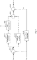
- FIG. 2 shows a schematic block diagram of the rotor side controller 31.
- the rotor side controller 31 includes a current regulator 311 and a modulator 312.
- the M-I compensator 313 is introduced into the current regulator 311.
- the rotor side controller 31 may also include a subtracter 314.
- the current regulator 311 may generate a rotor voltage command U cmd of the rotor 11 based on the rotor current error I error1 .
- the M-I compensator 313 may compensate the rotor voltage command U cmd to generate a compensated rotor voltage command U cmd1 .
- the modulator 312 may receive the compensated rotor voltage command U cmd1 , and generate a pulse width modulated signal S PWM based on the compensated rotor voltage command U cmd1 and send the pulse width modulated signal S PWM to the rotor side converter 21.
- the current regulator 311 includes a proportional-integral (PI) regulator.
- the PI regulator has a proportional controller 3111 and an integral controller 3112. Both the proportional controller 3111 and the integral controller 3112 receive the rotor current error I error1 , and the outputs of the proportional controller 3111 and the integral controller 3112 are summed by an adder 315 to obtain the rotor voltage command U cmd .
- K p and K i are the proportion and the integral coefficient respectively.
- the M-I compensator 313 is located downstream of the proportional controller 3111 and the integral controller 3112.
- the M-I compensator 313 may compensate the rotor voltage command U cmd to generate the compensated rotor voltage command U cmd1 .
- the M-I compensator 313 receives a rotational speed ⁇ r of the rotor 11 and has a transfer function related to the rotational speed ⁇ r of the rotor 11.
- K represents the transfer function
- s represents a Laplace operator
- j represents an imaginary unit
- ⁇ 0 represents a synchronous frequency of the stator side of the DFIG 10 (because the stator of the DFIG 10 is electrically coupled to the grid 50, so that the synchronous frequency of the stator side of the DFIG 10 is the frequency of the grid 50)
- ⁇ r represents the rotational speed of the rotor 11.
- ⁇ 1 and ⁇ 2 represent damping parameters used to enhance an internal stability of the power generation system 1. Values of ⁇ 1 and ⁇ 2 may be equal to 0. When the values of ⁇ 1 and ⁇ 2 in formula (4) are equal to 0, formula (3) can be obtained.
- the values of ⁇ 1 and ⁇ 2 can be determined based on one or more of an original control capability of the controller 30, a control object parameter of the power generation system 1, an external disturbance, and a dynamic response requirement of the power generation system 1. For example, when the original control capability of the controller 30 is strong, the value of ⁇ 1 and/or ⁇ 2 may be smaller, and when the original control capability of the controller 30 is weak, the value of ⁇ 1 and/or ⁇ 2 may be larger. When the external disturbance is small, the value of ⁇ 1 and/or ⁇ 2 may be smaller, and when the external disturbance is large, the value of ⁇ 1 and/or ⁇ 2 may be larger.
- the rotor voltage command U cmd can be multiplied by the transfer function of the M-I compensator 313 to obtain the compensated rotor voltage command cmd1 .
- the current regulator 311 may further include a decoupling controller 3113.
- the decoupling controller 3113 can improve the current response performance of the power generation system 1.
- the decoupling controller 3113 receives the rotor current feedback I fbk1 and outputs a decoupled voltage U d .
- the decoupling controller 3113 of the present invention is not limited to receiving only the rotor current feedback I fbk1 .
- the decoupling controller 3113 of the present invention can receive any one of the rotor current feedback I fbk1 , the rotor current command I cmd1 , and the rotor current error I error1 .
- the output of the M-I compensator 313 and the decoupled voltage U d are further summed by an adder 316 to obtain the compensated rotor voltage command U cmd1 .
- the compensated rotor voltage command U cmd1 includes the decoupled voltage U d .
- the M-I compensator 313 may also be disposed at other different positions of the current regulator 311. As shown in FIG. 4 , the M-I compensator 313 is located upstream of the proportional controller 3111 and the integral controller 3112. In the embodiment of FIG. 4 , the compensated rotor voltage command U cmd1 includes the decoupled voltage U d . As shown in FIG. 5 , the M-I compensator 313 may be located downstream of the proportional controller 3111. In the embodiment of FIG. 5 , the compensated rotor voltage command U cmd1 includes the decoupled voltage U d . As shown in FIG. 6 , the M-I compensator 313 may be located upstream of the proportional controller 3111. In the embodiment of FIG.
- the compensated rotor voltage command U cmd1 includes the decoupled voltage U d .
- the M-I compensator 313 may be located downstream of the proportional controller 3111, the integral controller 3112, and the decoupling controller 3113.
- the output of the adder 315 and the decoupled voltage U d are further summed by the adder 316 to obtain the rotor voltage command U cmd .
- the rotor voltage command U cmd includes the decoupled voltage Ud.
- the M-I compensator 313 can be always enabled.
- the M-I compensator 313 can be selectively enabled.
- the M-I compensator 313 when the power generation system 1 is connected to the grid 50 via a transmission line including the series compensation device 60, the M-I compensator 313 is enabled.
- the M-I compensator 313 when a frequency f of an AC component in the generator 10 is lower than the rotational speed ⁇ r of the rotor 11, the M-I compensator 313 is enabled.
- the power generation system 1 has the series compensation device 60 and the frequency f of the AC component in the generator 10 is lower than the rotational speed ⁇ r of the rotor 11, the M-I compensator 313 is enabled.
- FIG. 8 shows an illustration of equivalent conductance observed from a first direction D 1 and a second direction D 2 of FIG. 1 in a case in which the power generation system does not have the M-I compensator 313
- FIG. 9 shows an illustration of equivalent conductance observed from the first direction D 1 and the second direction D 2 of FIG. 1 in a case in which the power generation system has the M-I compensator 313.
- the horizontal axis represents the frequency f of the AC component of the generator 10 of the power generation system 1
- the vertical axis represents the real part of the admittance, that is, conductance G .
- the equivalent conductance observed from the stator side direction of the DFIG 10 represents equivalent conductance observed from the stator side direction of the DFIG 10, and the equivalent conductance observed from the second direction D 2 of FIG. 1 represents total conductance of the wind power generation system.
- the equivalent conductance observed from the first direction D 1 and the second direction D 2 of FIG. 1 is a negative value.
- the M-I compensator 313 when the M-I compensator 313 is introduced into the power generation system 1, the negative conductance observed from the first direction D 1 and the second direction D 2 of FIG. 1 can be removed by the M-I compensator 313, especially in a case of low frequencies.
- FIG. 10 shows an illustration of a DC bus voltage of the power generation system, a voltage at a point of common connection (PCC) P, and rotor current feedback in a case in which the power generation system does not have the M-I compensator 313.
- the series compensation device 60 is inserted into a transmission line for connecting the power generation system having no M-I compensator 313 and the grid. It can be seen from FIG. 10 , after the series compensation device 60 is inserted into the transmission line, the DC bus voltage of the power generation system, the voltage at the point of common connection P, and the rotor current feedback are oscillated due to the M-I effect of the DFIG 10.
- FIG. 11 shows an illustration of a DC bus voltage of the power generation system 1, a voltage at a point of common connection P, and rotor current feedback in a case in which the power generation system 1 has the M-I compensator 313. It can be seen from FIG. 11 , the M-I compensator 313 can make the power generation system 1 more stable after the series compensation device 60 is inserted into the transmission line.
- the M-I compensator 313 is introduced into the current regulator, so that the power generation system 1 of the present invention can directly counter the M-I effect of the DFIG 10, and therefore, it is possible to effectively suppress the sub-synchronous oscillation and ensure the stability of the system.
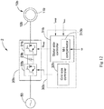
- FIG. 12 shows a schematic diagram of an exemplary power supply system 2 according to another embodiment of the present invention.
- the power supply system 2 of FIG. 12 includes an electric motor 10b, such as a squirrel cage motor.
- the power supply system 2 of FIG. 12 also includes a power converter 20b and a controller 30b.
- the power converter 20b is coupled between a stator 12b of the electric motor 10b and the grid 50, and includes a stator side converter 21b, a grid side converter 22b, and a DC bus 23b coupled between the stator side converter 21b and the grid side converter 22b.
- the stator side converter 21b is electrically coupled to the stator 12b of the electric motor 10b.
- the controller 30b includes a stator side controller 31b for controlling the stator side converter 21b and a grid side controller 32b for controlling the grid side converter 22b.
- the stator side controller 31b receives a stator current command I cmd2 of the stator 12b and stator current feedback I fbk2 of the stator 12b, and generates a stator voltage command of the stator 12b based on a stator current error between the stator current command I cmd2 and the stator current feedback I fbk2 .
- the M-I compensator 313b is introduced into the stator side controller 31b.
- the M-I compensator 313b can compensate the stator voltage command to generate a compensated stator voltage command so as to suppress sub-synchronous oscillations.
- the stator side controller 31b may generate a pulse width modulated signal S PWM based on the compensated stator voltage command and provide the pulse width modulated signal S PWM to the stator side converter 21b.
- the M-I compensator 313b of the power supply system 2 of FIG. 12 has a transfer function and position settings similar to the M-I compensator 313 of the power generation system 1 of FIG. 1 .
- ⁇ 0 and ⁇ r respectively represent a synchronous frequency on the stator side of the electric motor 10b and the rotational speed of the rotor 11b of the electric motor 10b.
- the M-I compensator of the present invention can be applied to a power generation system with a generator and a power supply system with an electric motor. Moreover, in fact, the M-I compensator of the present invention can be applied to any system having an induction machine and configured to suppress sub-synchronous oscillations.
- FIG. 13 shows a schematic diagram of an exemplary system 3 for suppressing sub-synchronous oscillations according to still another embodiment of the present invention.
- the system 3 of FIG. 13 includes an induction machine 10c, a power converter 20c, and a controller 30c.
- the power converter 20c is coupled between the induction machine 10c and the grid 50, and includes a first converter 21c coupled to the induction machine 10c, a second converter 22c coupled to the grid 50, and a DC bus 23c coupled between the first converter 21c and the second converter 22c.
- the controller 30c includes a first controller 31c for controlling the first converter 21c and a second controller 32c for controlling the second converter 22c.
- the first controller 31c includes an M-I compensator 313c for counteracting a negative resistance effect of the induction machine 10c to suppress sub-synchronous oscillations.
- the first controller 31c includes a current regulator and a modulator.
- the first controller 31c receives a current command I cmd of the induction machine 10c and current feedback I fbk of the induction machine 10c.
- the current regulator may generate a voltage command of the induction machine 10c based on a current error between the current command I cmd of the induction machine 10c and the current feedback I fbk of the induction machine 10c.
- the M-I compensator 313c is introduced to the current regulator and configured to compensate the voltage command of the induction machine 10c to generate a compensated voltage command.
- the modulator may generate a pulse width modulated signal S PWM based on the compensated rotor voltage command and send the pulse width modulated signal S PWM to the first converter 21c.
- the M-I compensator 313c of the system 3 of FIG. 13 has a transfer function and position settings similar to the M-I compensator 313 of the power generation system 1 of FIG. 1 .
- ⁇ 0 and ⁇ r respectively represent a synchronous frequency on the stator side of the induction machine 10c and the rotational speed of the rotor of the induction machine 10c.
- FIG. 14 shows a flowchart of an exemplary method for controlling operation of a power system according to an embodiment of the present invention. The method may include the following steps.
- step B1 first alternating current (AC) power is converted to direct current (DC) power by a power converter of the power system.
- the power converter includes a first converter coupled to an induction machine and a second converter coupled to a grid.
- the power system is a power generation system and the induction machine is a generator
- the first AC power is converted to DC power by the first converter.
- the power system is a power supply system and the induction machine is an electric motor
- the first AC power is converted to DC power by the second converter.
- step B2 the direct current (DC) power is converted to second alternating current (AC) power by the power converter.
- the DC power is converted to the second AC power by the second converter.
- the power system is a power supply system and the induction machine is an electric motor, the DC power is converted to the second AC power by the first converter.
- step B3 the first converter is controlled by a controller using a transfer function similar to the above to counter the negative resistance effect of the induction machine to suppress sub-synchronous oscillations.
- a transfer function associated with the rotational speed of the rotor of the induction machine is predetermined.
- the transfer function can be shown as the above formula (3) or (4).
- step B31 a current command of the induction machine, current feedback of the induction machine, and a rotational speed of the rotor are received.
- step B32 a current error between the current command and the current feedback is obtained.
- step B33 a voltage command of the induction machine is generated based on the current error.
- step B34 the voltage command is compensated using the transfer function predetermined in step B30 and the rotational speed of the rotor received in step B31, so as to generate a compensated voltage command.
- the transfer function is used to compensate the voltage B31, so as to generate a compensated voltage command.
- the transfer function is used to compensate the voltage command.
- the method of the present invention may include outputting a decoupled voltage based on one of the current feedback, current command, and current error.
- the voltage command or the compensated voltage command may include the decoupled voltage.
- step B35 a pulse width modulated signal is generated based on the compensated voltage command, and the pulse width modulated signal is provided to the first converter. Therefore, the negative resistance effect of the induction machine can be countered to suppress sub-synchronous oscillations of the power system.
- the steps of the method for controlling operation of the power system according to the embodiment of the present invention are shown as functional blocks, the order of respective functional blocks shown in FIGs. 14 and 15 and the actions for separation between the respective functional blocks are not intended to be limiting.
- various functional blocks may be executed in a different order, and the actions associated with a functional block may be combined with one or more other functional blocks or may be subdivided into multiple functional blocks.
- a method for controlling operation of a power system comprises:
Landscapes
- Engineering & Computer Science (AREA)
- Power Engineering (AREA)
- Life Sciences & Earth Sciences (AREA)
- Sustainable Development (AREA)
- Sustainable Energy (AREA)
- Chemical & Material Sciences (AREA)
- Combustion & Propulsion (AREA)
- Mechanical Engineering (AREA)
- General Engineering & Computer Science (AREA)
- Control Of Eletrric Generators (AREA)
Description
- The present invention generally relates to the field of sub-synchronous oscillation damping, and in particular, to a power generation system, a system for suppressing sub-synchronous oscillations, and a method for controlling operation of a power system.
- A power generation system typically includes a power converter for converting input power to power suitable for being applied to a load such as a generator, electric motor, power grid, or other suitable load. In many cases, the power generation system may be located in an area far away from the load it serves. Generally, such power generation systems are connected to the grid via a power system including a long transmission line. Such transmission lines usually include one or more series compensation components (for example, one or more capacitors), so as to facilitate reducing reactive losses in the transmission line, thereby increasing a power transfer capability of the transmission line. However, unfortunately, when the power generation system is connected to such a series-compensated transmission line, power-voltage oscillations occurred when a synchronous frequency is lower than that of the generator of the power generation system. This is called sub-synchronous oscillation (SSO) as e.g. described in the article "Sub-Synchronous Interaction Damping Control for DFIG Wind Turbines" by Andres E. Leon et al, (IEEE Transactions on Power Systems, 30/1, 419-428), and there may be a sub-synchronization instability problem in the power generation system.
WO 2016/119585 A1 describes A power oscillation suppression method for a double-fed wind turbine using a super capacitor energy storage system, comprising: connecting a super capacitor to a rotor side current transformer via a DC/DC interface circuit, the super capacitor and the rotor side current transformer of a double-fed wind turbine sharing a DC bus; and building an equivalent circuit. Sub-synchronous oscillations may cause unexpected system errors, damage to generators and other equipment in the power generation system, and reduce the operational reliability of the power generation system. The sub-synchronous oscillations may cause more threats to the power generation system based on a double-fed induction generator (DFIG) due to the negative damping at a sub-synchronous frequency caused by a motion-induction effect of the DFIG. In this case, the power system cannot provide sufficient damping, thus causing instability problems in the power generation system. - In view of this, the need of preventing sub-synchronous oscillations is becoming increasingly urgent.
- An aspect of the present invention provides a power generation system. The power generation system includes a double-fed induction generator, a power converter, and a controller. The double-fed induction generator includes a rotor and a stator coupled to a grid. The power converter includes a rotor side converter coupled to the rotor of the generator, a grid side converter coupled to the grid, and a DC bus coupled between the rotor side converter and the grid side converter. The controller includes a rotor side controller for controlling the rotor side converter and a grid side controller for controlling the grid side converter. The rotor side controller includes a compensator having a transfer function and configured to counter a negative resistance effect of the generator to suppress sub-synchronous oscillations. The transfer function is expressed in a synchronous coordinate system as follows:

- According to an example, a system for suppressing sub-synchronous oscillations includes an induction machine, a power converter, and a controller. The power converter includes a first converter coupled to the induction machine and a second converter coupled to a grid. The controller includes a first controller for controlling the first converter and a second controller for controlling the second converter. The first controller includes a compensator having a transfer function and configured to counter a negative resistance effect of the induction machine to suppress sub-synchronous oscillations, where the transfer function is expressed in a synchronous coordinate system as follows:

- Another aspect of the present invention provides a method for controlling operation of a power system. The method includes: converting, by using a power converter of the power system, first alternating current power to direct current power, where the power converter includes a first converter coupled to an induction machine and a second converter coupled to a grid; converting, by using the power converter, the direct current power to second alternating current power; and controlling the first converter by a controller using a transfer function to counter a negative resistance effect of the induction machine to suppress sub-synchronous oscillations, where the transfer function is expressed in a synchronous coordinate system as follows:

- Various features, aspects and advantages of the present invention will become better understood when the following detailed description is read with reference to the accompanying drawings, in which like reference numerals are used throughout the drawings to refer to like parts, where:
-
FIG. 1 is a schematic diagram of a power generation system according to an embodiment of the present invention; -
FIG. 2 is a schematic block diagram of a rotor side controller of the power generation system ofFIG. 1 ; -
FIGs. 3 to 7 show a compensator ofFIG. 2 in different positions in the rotor side controller; -
FIG. 8 is an illustration of equivalent conductance observed from a first direction and a second direction ofFIG. 1 in a case in which the power generation system has no compensator; -
FIG. 9 is an illustration of equivalent conductance observed from a first direction and a second direction ofFIG. 1 in a case in which the power generation system has a compensator; -
FIG. 10 is an illustration of a DC bus voltage of the power generation system, a voltage at a point of common connection, and rotor current feedback in a case in which the power generation system has no compensator; -
FIG. 11 is an illustration of a DC bus voltage of the power generation system, a voltage at a point of common connection, and rotor current feedback in a case in which the power generation system has a compensator; -
FIG. 12 is a schematic diagram of a power supply system according to another embodiment of the present invention; -
FIG. 13 is a schematic diagram of a system for suppressing sub-synchronous oscillations according to still another embodiment of the present invention; -
FIG. 14 is a flowchart of a method for controlling operation of a power system according to an embodiment of the present invention; and -
FIG. 15 shows detailed steps of how to control a first converter to counter a negative resistance effect of an induction machine inFIG. 14 . - The embodiments of the present invention will be described below in detail with reference to the accompanying drawings in order to facilitate those skilled in the art to exactly understand the subject matter claimed by the present invention. In the following detailed description of these specific embodiments, the present specification does not describe in detail any of the known functions or configurations, to avoid unnecessary details that may affect the disclosure of the present invention.
- Unless otherwise defined, the technical and scientific terms used in the claims and the specification are as they are usually understood by those skilled in the art to which the present invention pertains. "First", "second" and similar words used in the specification and the claims do not denote any order, quantity or importance, but are merely intended to distinguish between different constituents. The terms "one", "a" and similar words are not meant to be limiting, but rather denote the presence of at least one. "Comprising", "consisting of' and similar words mean that the elements or articles appearing before "comprising" or "consisting of' include the elements or articles and their equivalent elements appearing behind "comprising" or "consisting of', not excluding any other elements or articles. "Connected", "coupled" and similar words are not restricted to physical or mechanical connections, but may also include electrical connections, whether direct or indirect. Further, terms indicating a specific position, such as "top", "bottom", "left", "right", and the like are merely descriptions made with reference to specific drawings. Each embodiment disclosed herein may be placed in different ways as illustrated in the drawings of the present invention. Therefore, the positional terms used herein should not be limited to the positions shown in the specific embodiments.
-
FIG. 1 shows a schematic diagram of an exemplary power generation system 1 according to an embodiment of the present invention. As shown inFIG. 1 , for the purpose of description, the power generation system 1 in this embodiment is shown as a wind power generation system 1 as an example. The wind power generation system 1 includes a double-fed induction generator (DFIG) 10, apower converter 20, acontroller 30, and atransformer 40. - The DFIG 10 includes a
rotor 11 and astator 12. Thestator 12 is coupled to agrid 50 via thetransformer 40. Therotor 11 is coupled to awind turbine 13 via arotor shaft 14. Thewind turbine 13 is configured to rotate in response to wind energy received by thewind turbine 13 to drive the DFIG 10 such that the DFIG 10 outputs alternating current (AC) power. - The
power converter 20 includes arotor side converter 21, agrid side converter 22, and a DC bus (DC link) 23 coupled between therotor side converter 21 and thegrid side converter 22. Therotor side converter 21 is electrically coupled to therotor 11 of the DFIG 10 and is configured to convert AC power from therotor 11 of the DFIG 10 to direct current (DC) power. Thegrid side converter 22 is electrically coupled to thegrid 50 via thetransformer 40 and is configured to convert the DC power to AC power at a frequency compatible with thegrid 50. - The
transformer 40 is configured to provide voltage or current conversion between power from thepower converter 20 and power from thestator 12 of the DFIG 10 and provide isolation between thepower converter 20 and thegrid 50 and between the DFIG 10 and thegrid 50. Thetransformer 40 is configured to increase the amplitude of the AC voltage output from thegrid side converter 22 and thestator 12 of the DFIG 10 to match thegrid 50. - In an optional embodiment, the
stator 12 of the DFIG 10 and thegrid side converter 22, especially thetransformer 40, may be coupled to thegrid 50 via a transmission line including a series compensation device 60 (that is, a series compensation transmission line). Alternatively, theseries compensation device 60 may be connected in parallel with aswitch 70. That is, theseries compensation device 60 and theswitch 70 are connected in parallel in a transmission line between thegrid 50 and thetransformer 40. Therefore, the power generation system 1 can be selectively connected to a transmission line including theseries compensation device 60. - The
controller 30 is configured to control the operation of therotor side converter 21 and thegrid side converter 22. Thecontroller 30 may include one or more suitable programmable circuits or devices, such as a digital signal processor (DSP), a field programmable gate array (FPGA), a programmable logic controller (PLC), and an application specific integrated circuit (ASIC). Thecontroller 30 may be implemented in hardware, software, or a combination of hardware and software. - In the embodiment of
FIG. 1 , thecontroller 30 includes arotor side controller 31 and agrid side controller 32. Therotor side controller 31 is configured to control therotor side converter 21 and includes a motion-induction (M-I)compensator 313. TheM-I compensator 313 can counter a negative resistance effect of thegenerator 10 to suppress sub-synchronous oscillations. Thegrid side controller 32 is configured to control thegrid side converter 22. -
FIG. 2 shows a schematic block diagram of therotor side controller 31. Referring toFIG. 2 , therotor side controller 31 includes acurrent regulator 311 and amodulator 312. TheM-I compensator 313 is introduced into thecurrent regulator 311. Therotor side controller 31 may also include asubtracter 314. Thesubtracter 314 may receive a rotor current command Icmd1 of therotor 11 and rotor current feedback Ifbk1 of the rotor, and output a rotor current error Ierror1 between the rotor current command Icmd1 and the rotor current feedback Ifbk1, which is shown in the following formula:
- The
current regulator 311 may generate a rotor voltage command Ucmd of therotor 11 based on the rotor current error Ierror1. TheM-I compensator 313 may compensate the rotor voltage command Ucmd to generate a compensated rotor voltage command Ucmd1. Themodulator 312 may receive the compensated rotor voltage command Ucmd1, and generate a pulse width modulated signal SPWM based on the compensated rotor voltage command Ucmd1 and send the pulse width modulated signal SPWM to therotor side converter 21. - As shown in
FIG. 3 , in one embodiment, thecurrent regulator 311 includes a proportional-integral (PI) regulator. The PI regulator has aproportional controller 3111 and anintegral controller 3112. Both theproportional controller 3111 and theintegral controller 3112 receive the rotor current error Ierror1, and the outputs of theproportional controller 3111 and theintegral controller 3112 are summed by anadder 315 to obtain the rotor voltage command Ucmd. Specifically, the rotor voltage command Ucmd can be obtained as follows:
- In formula (2), Kp and Ki are the proportion and the integral coefficient respectively.
- In the embodiment of
FIG. 3 , theM-I compensator 313 is located downstream of theproportional controller 3111 and theintegral controller 3112. TheM-I compensator 313 may compensate the rotor voltage command Ucmd to generate the compensated rotor voltage command Ucmd1. TheM-I compensator 313 receives a rotational speed ωr of therotor 11 and has a transfer function related to the rotational speed ωr of therotor 11. - In one embodiment, the transfer function of the
M-I compensator 313 is expressed in a synchronous coordinate system as follows:
- In formula (3), K represents the transfer function, s represents a Laplace operator, j represents an imaginary unit, ω0 represents a synchronous frequency of the stator side of the DFIG 10 (because the stator of the
DFIG 10 is electrically coupled to thegrid 50, so that the synchronous frequency of the stator side of theDFIG 10 is the frequency of the grid 50), and ωr represents the rotational speed of therotor 11. - In another embodiment, to enhance the internal stability of the power generation system 1, the transfer function of the
M-I compensator 313 can be further expressed in a synchronous coordinate system as follows:
- In formula (4), σ 1 and σ 2 represent damping parameters used to enhance an internal stability of the power generation system 1. Values of σ 1 and σ 2 may be equal to 0. When the values of σ 1 and σ 2 in formula (4) are equal to 0, formula (3) can be obtained. The values of σ 1 and σ 2 can be determined based on one or more of an original control capability of the
controller 30, a control object parameter of the power generation system 1, an external disturbance, and a dynamic response requirement of the power generation system 1. For example, when the original control capability of thecontroller 30 is strong, the value of σ 1 and/or σ 2 may be smaller, and when the original control capability of thecontroller 30 is weak, the value of σ 1 and/or σ 2 may be larger. When the external disturbance is small, the value of σ 1 and/or σ 2 may be smaller, and when the external disturbance is large, the value of σ 1 and/or σ 2 may be larger. - Continue to refer to
FIG. 3 , the rotor voltage command Ucmd can be multiplied by the transfer function of theM-I compensator 313 to obtain the compensated rotor voltage command cmd1. - Optionally, the
current regulator 311 may further include adecoupling controller 3113. Thedecoupling controller 3113 can improve the current response performance of the power generation system 1. As an example, in the illustration of the present invention, thedecoupling controller 3113 receives the rotor current feedback Ifbk1 and outputs a decoupled voltage Ud. However, thedecoupling controller 3113 of the present invention is not limited to receiving only the rotor current feedback Ifbk1. In fact, thedecoupling controller 3113 of the present invention can receive any one of the rotor current feedback Ifbk1, the rotor current command Icmd1, and the rotor current error Ierror1. In the embodiment having thedecoupling controller 3113 shown inFIG. 3 , the output of theM-I compensator 313 and the decoupled voltage Ud are further summed by anadder 316 to obtain the compensated rotor voltage command Ucmd1. In this case, the compensated rotor voltage command Ucmd1 includes the decoupled voltage Ud. - Moreover, the
M-I compensator 313 may also be disposed at other different positions of thecurrent regulator 311. As shown inFIG. 4 , theM-I compensator 313 is located upstream of theproportional controller 3111 and theintegral controller 3112. In the embodiment ofFIG. 4 , the compensated rotor voltage command Ucmd1 includes the decoupled voltage Ud. As shown inFIG. 5 , theM-I compensator 313 may be located downstream of theproportional controller 3111. In the embodiment ofFIG. 5 , the compensated rotor voltage command Ucmd1 includes the decoupled voltage Ud. As shown inFIG. 6 , theM-I compensator 313 may be located upstream of theproportional controller 3111. In the embodiment ofFIG. 6 , the compensated rotor voltage command Ucmd1 includes the decoupled voltage Ud. As shown inFIG. 7 , theM-I compensator 313 may be located downstream of theproportional controller 3111, theintegral controller 3112, and thedecoupling controller 3113. In the embodiment ofFIG. 7 , the output of theadder 315 and the decoupled voltage Ud are further summed by theadder 316 to obtain the rotor voltage command Ucmd. In this case, the rotor voltage command Ucmd includes the decoupled voltage Ud. - In the power generation system 1 of the present invention, the
M-I compensator 313 can be always enabled. Alternatively, theM-I compensator 313 can be selectively enabled. For example, in one embodiment, when the power generation system 1 is connected to thegrid 50 via a transmission line including theseries compensation device 60, theM-I compensator 313 is enabled. In another embodiment, when a frequency f of an AC component in thegenerator 10 is lower than the rotational speed ωr of therotor 11, theM-I compensator 313 is enabled. In still another embodiment, when the power generation system 1 has theseries compensation device 60 and the frequency f of the AC component in thegenerator 10 is lower than the rotational speed ωr of therotor 11, theM-I compensator 313 is enabled. -
FIG. 8 shows an illustration of equivalent conductance observed from a first direction D1 and a second direction D2 ofFIG. 1 in a case in which the power generation system does not have theM-I compensator 313, andFIG. 9 shows an illustration of equivalent conductance observed from the first direction D1 and the second direction D2 ofFIG. 1 in a case in which the power generation system has theM-I compensator 313. For clarity of illustration, inFIGs. 8 and 9 , the horizontal axis represents the frequency f of the AC component of thegenerator 10 of the power generation system 1, and the vertical axis represents the real part of the admittance, that is, conductance G. In addition, the equivalent conductance observed from the first direction D1 ofFIG. 1 represents equivalent conductance observed from the stator side direction of theDFIG 10, and the equivalent conductance observed from the second direction D2 ofFIG. 1 represents total conductance of the wind power generation system. As shown inFIG. 8 , when the power generation system does not have theM-I compensator 313, the equivalent conductance observed from the first direction D1 and the second direction D2 ofFIG. 1 is a negative value. However, as shown inFIG. 9 , when theM-I compensator 313 is introduced into the power generation system 1, the negative conductance observed from the first direction D1 and the second direction D2 ofFIG. 1 can be removed by theM-I compensator 313, especially in a case of low frequencies. -
FIG. 10 shows an illustration of a DC bus voltage of the power generation system, a voltage at a point of common connection (PCC) P, and rotor current feedback in a case in which the power generation system does not have theM-I compensator 313. Referring toFIG. 10 , at time T0, theseries compensation device 60 is inserted into a transmission line for connecting the power generation system having noM-I compensator 313 and the grid. It can be seen fromFIG. 10 , after theseries compensation device 60 is inserted into the transmission line, the DC bus voltage of the power generation system, the voltage at the point of common connection P, and the rotor current feedback are oscillated due to the M-I effect of theDFIG 10. Therefore, in order to suppress sub-synchronous oscillations of the power generation system, theM-I compensator 313 of the present invention can be introduced into the power generation system 1.FIG. 11 shows an illustration of a DC bus voltage of the power generation system 1, a voltage at a point of common connection P, and rotor current feedback in a case in which the power generation system 1 has theM-I compensator 313. It can be seen fromFIG. 11 , theM-I compensator 313 can make the power generation system 1 more stable after theseries compensation device 60 is inserted into the transmission line. - The
M-I compensator 313 is introduced into the current regulator, so that the power generation system 1 of the present invention can directly counter the M-I effect of theDFIG 10, and therefore, it is possible to effectively suppress the sub-synchronous oscillation and ensure the stability of the system. -
FIG. 12 shows a schematic diagram of an exemplarypower supply system 2 according to another embodiment of the present invention. Different from the power generation system 1 ofFIG. 1 , thepower supply system 2 ofFIG. 12 includes anelectric motor 10b, such as a squirrel cage motor. Thepower supply system 2 ofFIG. 12 also includes apower converter 20b and acontroller 30b. - In the
power supply system 2 ofFIG. 12 , thepower converter 20b is coupled between astator 12b of theelectric motor 10b and thegrid 50, and includes astator side converter 21b, agrid side converter 22b, and aDC bus 23b coupled between thestator side converter 21b and thegrid side converter 22b. Thestator side converter 21b is electrically coupled to thestator 12b of theelectric motor 10b. Thecontroller 30b includes astator side controller 31b for controlling thestator side converter 21b and agrid side controller 32b for controlling thegrid side converter 22b. Thestator side controller 31b receives a stator current command Icmd2 of thestator 12b and stator current feedback Ifbk2 of thestator 12b, and generates a stator voltage command of thestator 12b based on a stator current error between the stator current command Icmd2 and the stator current feedback Ifbk2. To compensate the negative resistance effect of theelectric motor 10b, theM-I compensator 313b is introduced into thestator side controller 31b. TheM-I compensator 313b can compensate the stator voltage command to generate a compensated stator voltage command so as to suppress sub-synchronous oscillations. Thestator side controller 31b may generate a pulse width modulated signal SPWM based on the compensated stator voltage command and provide the pulse width modulated signal SPWM to thestator side converter 21b. TheM-I compensator 313b of thepower supply system 2 ofFIG. 12 has a transfer function and position settings similar to theM-I compensator 313 of the power generation system 1 ofFIG. 1 . - It can be understood that since the
power supply system 2 ofFIG. 12 uses theelectric motor 10b to replace thegenerator 10 of the power generation system 1 ofFIG. 1 , in the transfer function of theM-I compensator 313b of thepower supply system 2, ω0 and ωr respectively represent a synchronous frequency on the stator side of theelectric motor 10b and the rotational speed of therotor 11b of theelectric motor 10b. - The M-I compensator of the present invention can be applied to a power generation system with a generator and a power supply system with an electric motor. Moreover, in fact, the M-I compensator of the present invention can be applied to any system having an induction machine and configured to suppress sub-synchronous oscillations. For example,
FIG. 13 shows a schematic diagram of anexemplary system 3 for suppressing sub-synchronous oscillations according to still another embodiment of the present invention. Thesystem 3 ofFIG. 13 includes aninduction machine 10c, apower converter 20c, and acontroller 30c. - In the
system 3 ofFIG. 13 , thepower converter 20c is coupled between theinduction machine 10c and thegrid 50, and includes afirst converter 21c coupled to theinduction machine 10c, asecond converter 22c coupled to thegrid 50, and aDC bus 23c coupled between thefirst converter 21c and thesecond converter 22c. Thecontroller 30c includes afirst controller 31c for controlling thefirst converter 21c and asecond controller 32c for controlling thesecond converter 22c. Thefirst controller 31c includes anM-I compensator 313c for counteracting a negative resistance effect of theinduction machine 10c to suppress sub-synchronous oscillations. - The
first controller 31c includes a current regulator and a modulator. Thefirst controller 31c receives a current command Icmd of theinduction machine 10c and current feedback Ifbk of theinduction machine 10c. The current regulator may generate a voltage command of theinduction machine 10c based on a current error between the current command Icmd of theinduction machine 10c and the current feedback Ifbk of theinduction machine 10c. TheM-I compensator 313c is introduced to the current regulator and configured to compensate the voltage command of theinduction machine 10c to generate a compensated voltage command. The modulator may generate a pulse width modulated signal SPWM based on the compensated rotor voltage command and send the pulse width modulated signal SPWM to thefirst converter 21c. TheM-I compensator 313c of thesystem 3 ofFIG. 13 has a transfer function and position settings similar to theM-I compensator 313 of the power generation system 1 ofFIG. 1 . - It can be understood that since the
system 3 ofFIG. 13 uses theinduction machine 10c to replace thegenerator 10 of the power generation system 1 ofFIG. 1 , in the transfer function of theM-I compensator 313c of thesystem 3, ω0 and ωr respectively represent a synchronous frequency on the stator side of theinduction machine 10c and the rotational speed of the rotor of theinduction machine 10c. -
FIG. 14 shows a flowchart of an exemplary method for controlling operation of a power system according to an embodiment of the present invention. The method may include the following steps. - As shown in
FIG. 14 , in step B1, first alternating current (AC) power is converted to direct current (DC) power by a power converter of the power system. The power converter includes a first converter coupled to an induction machine and a second converter coupled to a grid. When the power system is a power generation system and the induction machine is a generator, the first AC power is converted to DC power by the first converter. When the power system is a power supply system and the induction machine is an electric motor, the first AC power is converted to DC power by the second converter. - In step B2, the direct current (DC) power is converted to second alternating current (AC) power by the power converter. When the power system is a power generation system and the induction machine is a generator, the DC power is converted to the second AC power by the second converter. When the power system is a power supply system and the induction machine is an electric motor, the DC power is converted to the second AC power by the first converter.
- In step B3, the first converter is controlled by a controller using a transfer function similar to the above to counter the negative resistance effect of the induction machine to suppress sub-synchronous oscillations.
- How the first converter is controlled by the controller in step B3 of
FIG. 14 will be described in detail below with reference toFIG. 15 . - In step B30 of
FIG. 15 , a transfer function associated with the rotational speed of the rotor of the induction machine is predetermined. The transfer function can be shown as the above formula (3) or (4). - In step B31, a current command of the induction machine, current feedback of the induction machine, and a rotational speed of the rotor are received.
- In step B32, a current error between the current command and the current feedback is obtained.
- In step B33, a voltage command of the induction machine is generated based on the current error.
- In step B34, the voltage command is compensated using the transfer function predetermined in step B30 and the rotational speed of the rotor received in step B31, so as to generate a compensated voltage command. As an example, when the frequency of an AC component in the induction machine is lower than the rotational speed of the rotor, the transfer function is used to compensate the voltage B31, so as to generate a compensated voltage command. As an example, when the frequency of an AC component in the induction machine is lower than the rotational speed of the rotor, the transfer function is used to compensate the voltage command.
- In an optional embodiment, the method of the present invention may include outputting a decoupled voltage based on one of the current feedback, current command, and current error. In this case, the voltage command or the compensated voltage command may include the decoupled voltage.
- In step B35, a pulse width modulated signal is generated based on the compensated voltage command, and the pulse width modulated signal is provided to the first converter. Therefore, the negative resistance effect of the induction machine can be countered to suppress sub-synchronous oscillations of the power system.
- Although the steps of the method for controlling operation of the power system according to the embodiment of the present invention are shown as functional blocks, the order of respective functional blocks shown in
FIGs. 14 and15 and the actions for separation between the respective functional blocks are not intended to be limiting. For example, various functional blocks may be executed in a different order, and the actions associated with a functional block may be combined with one or more other functional blocks or may be subdivided into multiple functional blocks. - According to an embodiment, a method for controlling operation of a power system comprises:
- converting, by using a power converter of the power system, first alternating current power to direct current power, wherein the power converter comprises a first converter coupled to an induction machine and a second converter coupled to a grid;
- converting, by using the power converter, the direct current power to second alternating current power; and
- controlling the first converter by a controller using a transfer function to counter a negative resistance effect of the induction machine to suppress sub-synchronous oscillations, wherein the transfer function is expressed in a synchronous coordinate system as follows:

- wherein the first alternating current power is converted to the direct current power by the first converter, and the direct current power is converted to the second alternating current power by the second converter, or
- wherein the first alternating current power is converted to the direct current power by the second converter, and the direct current power is converted to the second alternating current power by the first converter.
Claims (15)
- A power generation system (1), comprising:a double-fed induction generator (10) comprising a rotor (11) and a stator (12) coupled to a grid (50);a power converter (20) comprising a rotor side converter (21) coupled to the rotor of the generator, a grid side converter (22) coupled to the grid, and a DC bus coupled between the rotor side converter and the grid side converter; anda controller (30) comprising a rotor side controller (31) for controlling the rotor side converter and a grid side controller (32) for controlling the grid side converter, the rotor side controller comprising a compensator (60) having a transfer function and configured to counter a negative resistance effect of the generator to suppress sub-synchronous oscillations, characterised in that the transfer function is expressed in a synchronous coordinate system as follows:

- The power generation system (1) according to claim 1, wherein the compensator (60) is configured to be enabled when a frequency of an AC component in the generator is lower than the rotational speed of the rotor.
- The power generation system (1) according to any proceeding claim, wherein the rotor side controller (31) comprises:a current regulator (311), configured to generate a rotor voltage command of the rotor based on a rotor current error between a rotor current command of the rotor and rotor current feedback of the rotor, wherein the compensator is introduced to the current regulator and configured to compensate the rotor voltage command so as to generate a compensated rotor voltage command; anda modulator, configured to generate a pulse width modulated signal to the rotor side converter based on the compensated rotor voltage command.
- The power generation system (1) according to claim 3, wherein the current regulator (311) comprises a proportional-integral regulator having a proportional controller and an integral controller.
- The power generation system (1) according to claim 4, wherein the compensator (60) is located upstream or downstream of the proportional controller.
- The power generation system (1) according to claim 4 or 5, wherein the compensator (60) is located upstream or downstream of the proportional controller and the integral controller.
- The power generation system (1) according to any preceding claim, wherein the current regulator (311) further comprises a decoupling controller for improving current response performance of the power generation system.
- The power generation system (1) according to claim 7, wherein the decoupling controller is configured to receive one of the rotor current feedback, the rotor current command, and the rotor current error, and output a decoupled voltage, and the rotor voltage command or the compensated rotor voltage command comprises the decoupled voltage.
- The power generation system (1) according to claim 7 or 8, wherein the compensator (60) is located downstream of the proportional controller, the integral controller, and the decoupling controller.
- The power generation system (1) according to any preceding claim, wherein the stator of the generator (10) and the grid side converter are connected to the grid (50) via a series compensation transmission line.
- The power generation system (1) according to any preceding claim, wherein the power generation system comprises a wind power generation system.
- A method for controlling operation of a power system (1), comprising:converting, by using a power converter (20) of the power system, first alternating current power to direct current power, wherein the power converter (20) comprises a first converter (21) coupled to an induction machine and a second converter (22) coupled to a grid (50);converting, by using the power converter, the direct current power to second alternating current power; andcontrolling the first converter (21) by a controller (30) using a transfer function to counter a negative resistance effect of the induction machine to suppress sub-synchronous oscillations, characterised in that the transfer function is expressed in a synchronous coordinate system as follows:

- The method according to claim 12, wherein controlling the first converter (21) by the controller (30) comprises:predetermining the transfer function;receiving a current command of the induction machine, current feedback of the induction machine, and the rotational speed of the rotor;obtaining a current error between the current command and the current feedback;generating a voltage command of the induction machine based on the current error;compensating the voltage command by using the transfer function and the received rotational speed of the rotor so as to generate a compensated voltage command; andgenerating a pulse width modulated signal to the first converter (21) based on the compensated voltage command.
- The method according to claim 12 or 13, comprising:
outputting a decoupled voltage based on one of the current feedback, the current command, and the current error, the voltage command or the compensated voltage command comprising the decoupled voltage. - The method according to any of the claims 12 to 14, wherein the transfer function is used to compensate the voltage command when a frequency of an AC component in the induction machine is lower than the rotational speed of the rotor.
Applications Claiming Priority (1)
| Application Number | Priority Date | Filing Date | Title |
|---|---|---|---|
| CN201710858081.2A CN109546664B (en) | 2017-09-21 | 2017-09-21 | Power generation system, system for suppressing subsynchronous oscillations, and method for controlling operation of power system |
Publications (2)
| Publication Number | Publication Date |
|---|---|
| EP3460943A1 EP3460943A1 (en) | 2019-03-27 |
| EP3460943B1 true EP3460943B1 (en) | 2020-10-28 |
Family
ID=63667828
Family Applications (1)
| Application Number | Title | Priority Date | Filing Date |
|---|---|---|---|
| EP18195809.1A Active EP3460943B1 (en) | 2017-09-21 | 2018-09-20 | Power generation system, system for suppressing sub-synchronous oscillations, and method for controlling operation of power system |
Country Status (5)
| Country | Link |
|---|---|
| US (1) | US10819262B2 (en) |
| EP (1) | EP3460943B1 (en) |
| CN (1) | CN109546664B (en) |
| DK (1) | DK3460943T3 (en) |
| ES (1) | ES2847423T3 (en) |
Families Citing this family (10)
| Publication number | Priority date | Publication date | Assignee | Title |
|---|---|---|---|---|
| ES2902395T3 (en) | 2018-10-05 | 2022-03-28 | Vestas Wind Sys As | A method for handling subsynchronous resonances |
| EP3731364A1 (en) | 2019-04-23 | 2020-10-28 | Siemens Gamesa Renewable Energy A/S | System and method for supplying electric power to a grid and for supporting the grid by use of a virtual synchronous machine and an energy storage system |
| CN110098624B (en) * | 2019-05-17 | 2020-10-16 | 华中科技大学 | An additional control method and system for a doubly-fed fan for optimizing system frequency dynamics |
| CN110350587B (en) * | 2019-07-30 | 2020-09-04 | 华北电力大学 | Doubly-fed fan subsynchronous oscillation suppression method and system based on converter control |
| CN111245013B (en) * | 2020-02-27 | 2022-05-13 | 华北电力大学 | DFIG subsynchronous oscillation suppression method based on multi-branch impedance remodeling |
| CN111786405B (en) * | 2020-06-23 | 2024-04-23 | 湖南大学 | New energy power plant series compensation grid-connected system and method for suppressing subsynchronous oscillation |
| CN111525575B (en) * | 2020-07-06 | 2020-10-16 | 深圳华工能源技术有限公司 | Voltage stabilization energy conservation and harmonic suppression energy conservation coordination control method |
| CN112886610B (en) * | 2021-01-20 | 2022-08-02 | 合肥工业大学 | Doubly-fed wind power plant control system and method for realizing subsynchronous oscillation suppression |
| CN113193574B (en) * | 2021-04-30 | 2022-08-02 | 华中科技大学 | Subsynchronous oscillation suppression method and device based on impedance characteristics of ports of doubly-fed wind turbine |
| CN114784826B (en) * | 2022-05-11 | 2024-08-02 | 华北电力大学 | Stability control method and system for doubly-fed wind power plant grid-connected system |
Family Cites Families (28)
| Publication number | Priority date | Publication date | Assignee | Title |
|---|---|---|---|---|
| US8063515B2 (en) * | 2008-10-10 | 2011-11-22 | General Electric Company | Compensation system for power transmission |
| CN101615791B (en) | 2009-07-29 | 2011-08-17 | 清华大学 | Subsynchronous damping control system for effectively inhibiting subsynchronous resonance and oscillation |
| US8310074B2 (en) * | 2009-10-30 | 2012-11-13 | General Electric Company | Method and apparatus for generating power in a wind turbine |
| WO2011112571A2 (en) * | 2010-03-11 | 2011-09-15 | Siemens Energy, Inc. | Method and system for damping subsynchronous resonant oscillations in a power system using a wind turbine |
| US8558405B2 (en) * | 2011-05-26 | 2013-10-15 | Siemens Aktiengesellschaft | Method and system for operating and controlling a wind turbine to prevent excitation of subsynchronous oscillations within the wind turbine |
| US9728969B2 (en) * | 2011-05-31 | 2017-08-08 | Vestas Wind Systems A/S | Systems and methods for generating an inertial response to a change in the voltage of an electricial grid |
| DK2544358T3 (en) | 2011-07-08 | 2017-02-20 | Abb Technology Oy | Double supply induction machine control system |
| US8258642B2 (en) * | 2011-09-27 | 2012-09-04 | General Electric Company | Method and system for resonance dampening in wind turbines |
| US9455633B2 (en) * | 2012-01-05 | 2016-09-27 | Ingeteam Power Technology, S.A. | Method and apparatus for controlling a frequency converter |
| CN102684209B (en) | 2012-06-18 | 2014-09-10 | 中国电力科学研究院 | Method for improving sub-synchronous oscillation (SSO) damping of thermal power plant by utilizing fan supplementary controller |
| CN102769296B (en) | 2012-07-04 | 2015-02-25 | 华北电力大学 | Supplementary subsynchronous damping control method of speed regulator |
| CN103259473A (en) * | 2013-04-19 | 2013-08-21 | 上海交通大学 | Subsynchronous Oscillation Anti-Oscillation Suppression System and Control Method Based on SVC |
| CN103269082A (en) * | 2013-04-19 | 2013-08-28 | 上海交通大学 | Anti-oscillation suppression system and method for subsynchronous oscillation of large generating set |
| CN103475011A (en) | 2013-09-25 | 2013-12-25 | 华北电力大学 | STATCOM-and-TCSC combined subsynchronous oscillation restraining method |
| US9548690B2 (en) * | 2014-02-28 | 2017-01-17 | General Electric Company | System and method for adjusting current regulator gains applied within a power generation system |
| CN104638661A (en) * | 2015-01-27 | 2015-05-20 | 国家电网公司 | Double-fed wind turbine generator power oscillation restraining method adopting super capacitor energy storage system |
| PT3166197T (en) * | 2015-02-02 | 2022-09-02 | Ingeteam Power Tech Sa | CONTROL METHOD FOR A SYSTEM COMPRISING A FREQUENCY CONVERTER CONNECTED TO AN ELECTRICAL GRID |
| DE102015003170A1 (en) | 2015-03-13 | 2016-09-15 | Senvion Gmbh | Wind turbine with sub-synchronous vibration suppression |
| CN105024388A (en) | 2015-04-28 | 2015-11-04 | 华北电力大学 | Sub-synchronous oscillation suppression method based on modal damping current injection |
| WO2017000945A1 (en) * | 2015-06-29 | 2017-01-05 | Vestas Wind Systems A/S | Sub-synchronous resonance damping |
| CN105048482B (en) | 2015-08-28 | 2018-05-08 | 中国神华能源股份有限公司 | A kind of control device and method for improving sub-synchronous oscillation positive damping |
| CN105186543B (en) * | 2015-08-28 | 2018-10-30 | 中国神华能源股份有限公司 | A kind of parameter tuning device and method of subsynchronous oscillation damping controller |
| CN105633981B (en) | 2016-01-06 | 2018-03-23 | 江苏省电力公司电力科学研究院 | A kind of THE UPFC additional longitudinal forces system for suppressing sub-synchronous oscillation |
| CN105515020B (en) * | 2016-01-19 | 2018-02-02 | 思源清能电气电子有限公司 | A kind of suppression sub-synchronous oscillation control method and system based on SVG |
| CN105978021A (en) * | 2016-05-03 | 2016-09-28 | 上海交通大学 | Method of restraining doubly-fed induction wind generator subsynchronous control interaction |
| CN105939018A (en) * | 2016-05-03 | 2016-09-14 | 上海交通大学 | Double-fed type wind power generator set current converter PI based subsynchronous oscillation suppression method |
| CN106329571A (en) * | 2016-09-14 | 2017-01-11 | 国网河南省电力公司平顶山供电公司 | Operation control method of DFIG grid side and rotor side PWM converter |
| US10707789B2 (en) * | 2017-05-12 | 2020-07-07 | General Electric Company | Adaptive current damping module for improved power converter control in wind turbine systems |
-
2017
- 2017-09-21 CN CN201710858081.2A patent/CN109546664B/en active Active
-
2018
- 2018-09-10 US US16/126,110 patent/US10819262B2/en active Active
- 2018-09-20 EP EP18195809.1A patent/EP3460943B1/en active Active
- 2018-09-20 DK DK18195809.1T patent/DK3460943T3/en active
- 2018-09-20 ES ES18195809T patent/ES2847423T3/en active Active
Non-Patent Citations (1)
| Title |
|---|
| DORIA-CEREZO ARNAU ET AL: "Design of Controllers for Electrical Power Systems Using a Complex Root Locus Method", IEEE TRANSACTIONS ON INDUSTRIAL ELECTRONICS, IEEE SERVICE CENTER, PISCATAWAY, NJ, USA, vol. 63, no. 6, 1 June 2016 (2016-06-01), pages 3706 - 3716, XP011609598, ISSN: 0278-0046, [retrieved on 20160510], DOI: 10.1109/TIE.2016.2521599 * |
Also Published As
| Publication number | Publication date |
|---|---|
| US20190089279A1 (en) | 2019-03-21 |
| EP3460943A1 (en) | 2019-03-27 |
| DK3460943T3 (en) | 2021-01-25 |
| CN109546664A (en) | 2019-03-29 |
| CN109546664B (en) | 2022-05-24 |
| ES2847423T3 (en) | 2021-08-03 |
| US10819262B2 (en) | 2020-10-27 |
Similar Documents
| Publication | Publication Date | Title |
|---|---|---|
| EP3460943A1 (en) | Power generation system, system for suppressing sub-synchronous oscillations, and method for controlling operation of power system | |
| CN114977270A (en) | Self-synchronizing voltage source full power conversion wind turbine control system | |
| EP2865889B1 (en) | Damping of wind turbine drive train oscillations | |
| US20110103110A1 (en) | Method of operating an inverter and inverter control arrangement | |
| EP3635838B1 (en) | Adaptive current damping method and system for improved power converter control in wind turbine systems and control system | |
| CN103337877B (en) | Direct-current voltage control unit and method for wind power generation system | |
| CN110611321B (en) | A design method of virtual power system stabilizer for compensating the negative damping characteristics of virtual synchronous machine | |
| CN107732939A (en) | Suppression sub-synchronous oscillation control method based on voltage source type converter uneoupled control | |
| CN104242759A (en) | Double-fed wind power generation system based on vector power system stabilizer | |
| WO2020024064A1 (en) | Controller for power inverter | |
| Ramachandran et al. | Systematized active power control of PMSG-based wind-driven generators | |
| CN109066735B (en) | A double-fed wind power generation system under unbalanced grid voltage and its control method | |
| CN109004680A (en) | Wind power control method and system based on energy storage inverter | |
| Li et al. | New control schemes of output power decoupling based on synchronverter | |
| WO2023177393A1 (en) | System and method for mitigating sub-synchronous oscillations in an inverter-based resource | |
| US10404198B2 (en) | Controlling the energy flow from an electrical machine with unbalanced impedance | |
| Haisheng et al. | Stability analysis and control strategy for multi-machine parallel system with grid-forming inverters | |
| CN118783527A (en) | A grid-connected converter, a grid-connected system and a control method | |
| CN117791693A (en) | Converter control method, device, equipment and medium for flexible DC transmission system | |
| CN118249679A (en) | Torque ripple suppression method for brushless double-fed DC generator system with power winding phase failure | |
| Zhang et al. | Control of hvdc-connected pmsg-based wind turbines for power system oscillation damping | |
| Dinesh et al. | Independent operation of DFIG-based WECS using resonant feedback compensators under unbalanced grid voltage conditions | |
| Shokri et al. | Performance improvement of DFIG-based wind farm using multilevel cascaded H-bridge converter under unbalanced grid voltage conditions | |
| Tayab et al. | A modified droop controller for parallel operation of single-phase inverters in Islanded microgrid | |
| Molina et al. | Control of tie-line power flow of microgrid including wind generation by DSTATCOM-SMES controller |
Legal Events
| Date | Code | Title | Description |
|---|---|---|---|
| PUAI | Public reference made under article 153(3) epc to a published international application that has entered the european phase |
Free format text: ORIGINAL CODE: 0009012 |
|
| STAA | Information on the status of an ep patent application or granted ep patent |
Free format text: STATUS: THE APPLICATION HAS BEEN PUBLISHED |
|
| AK | Designated contracting states |
Kind code of ref document: A1 Designated state(s): AL AT BE BG CH CY CZ DE DK EE ES FI FR GB GR HR HU IE IS IT LI LT LU LV MC MK MT NL NO PL PT RO RS SE SI SK SM TR |
|
| AX | Request for extension of the european patent |
Extension state: BA ME |
|
| STAA | Information on the status of an ep patent application or granted ep patent |
Free format text: STATUS: REQUEST FOR EXAMINATION WAS MADE |
|
| 17P | Request for examination filed |
Effective date: 20190923 |
|
| RBV | Designated contracting states (corrected) |
Designated state(s): AL AT BE BG CH CY CZ DE DK EE ES FI FR GB GR HR HU IE IS IT LI LT LU LV MC MK MT NL NO PL PT RO RS SE SI SK SM TR |
|
| GRAP | Despatch of communication of intention to grant a patent |
Free format text: ORIGINAL CODE: EPIDOSNIGR1 |
|
| STAA | Information on the status of an ep patent application or granted ep patent |
Free format text: STATUS: GRANT OF PATENT IS INTENDED |
|
| RIC1 | Information provided on ipc code assigned before grant |
Ipc: H02J 3/24 20060101AFI20200415BHEP Ipc: H02P 9/10 20060101ALI20200415BHEP Ipc: H02J 3/38 20060101ALI20200415BHEP |
|
| INTG | Intention to grant announced |
Effective date: 20200512 |
|
| GRAS | Grant fee paid |
Free format text: ORIGINAL CODE: EPIDOSNIGR3 |
|
| GRAA | (expected) grant |
Free format text: ORIGINAL CODE: 0009210 |
|
| STAA | Information on the status of an ep patent application or granted ep patent |
Free format text: STATUS: THE PATENT HAS BEEN GRANTED |
|
| AK | Designated contracting states |
Kind code of ref document: B1 Designated state(s): AL AT BE BG CH CY CZ DE DK EE ES FI FR GB GR HR HU IE IS IT LI LT LU LV MC MK MT NL NO PL PT RO RS SE SI SK SM TR |
|
| REG | Reference to a national code |
Ref country code: GB Ref legal event code: FG4D |
|
| REG | Reference to a national code |
Ref country code: CH Ref legal event code: EP |
|
| REG | Reference to a national code |
Ref country code: AT Ref legal event code: REF Ref document number: 1329197 Country of ref document: AT Kind code of ref document: T Effective date: 20201115 |
|
| REG | Reference to a national code |
Ref country code: DE Ref legal event code: R096 Ref document number: 602018009099 Country of ref document: DE |
|
| REG | Reference to a national code |
Ref country code: IE Ref legal event code: FG4D |
|
| REG | Reference to a national code |
Ref country code: DK Ref legal event code: T3 Effective date: 20210121 |
|
| REG | Reference to a national code |
Ref country code: AT Ref legal event code: MK05 Ref document number: 1329197 Country of ref document: AT Kind code of ref document: T Effective date: 20201028 |
|
| REG | Reference to a national code |
Ref country code: NL Ref legal event code: MP Effective date: 20201028 |
|
| PG25 | Lapsed in a contracting state [announced via postgrant information from national office to epo] |
Ref country code: FI Free format text: LAPSE BECAUSE OF FAILURE TO SUBMIT A TRANSLATION OF THE DESCRIPTION OR TO PAY THE FEE WITHIN THE PRESCRIBED TIME-LIMIT Effective date: 20201028 Ref country code: PT Free format text: LAPSE BECAUSE OF FAILURE TO SUBMIT A TRANSLATION OF THE DESCRIPTION OR TO PAY THE FEE WITHIN THE PRESCRIBED TIME-LIMIT Effective date: 20210301 Ref country code: RS Free format text: LAPSE BECAUSE OF FAILURE TO SUBMIT A TRANSLATION OF THE DESCRIPTION OR TO PAY THE FEE WITHIN THE PRESCRIBED TIME-LIMIT Effective date: 20201028 Ref country code: NO Free format text: LAPSE BECAUSE OF FAILURE TO SUBMIT A TRANSLATION OF THE DESCRIPTION OR TO PAY THE FEE WITHIN THE PRESCRIBED TIME-LIMIT Effective date: 20210128 Ref country code: GR Free format text: LAPSE BECAUSE OF FAILURE TO SUBMIT A TRANSLATION OF THE DESCRIPTION OR TO PAY THE FEE WITHIN THE PRESCRIBED TIME-LIMIT Effective date: 20210129 |
|
| REG | Reference to a national code |
Ref country code: LT Ref legal event code: MG4D |
|
| PG25 | Lapsed in a contracting state [announced via postgrant information from national office to epo] |
Ref country code: BG Free format text: LAPSE BECAUSE OF FAILURE TO SUBMIT A TRANSLATION OF THE DESCRIPTION OR TO PAY THE FEE WITHIN THE PRESCRIBED TIME-LIMIT Effective date: 20210128 Ref country code: IS Free format text: LAPSE BECAUSE OF FAILURE TO SUBMIT A TRANSLATION OF THE DESCRIPTION OR TO PAY THE FEE WITHIN THE PRESCRIBED TIME-LIMIT Effective date: 20210228 Ref country code: LV Free format text: LAPSE BECAUSE OF FAILURE TO SUBMIT A TRANSLATION OF THE DESCRIPTION OR TO PAY THE FEE WITHIN THE PRESCRIBED TIME-LIMIT Effective date: 20201028 Ref country code: PL Free format text: LAPSE BECAUSE OF FAILURE TO SUBMIT A TRANSLATION OF THE DESCRIPTION OR TO PAY THE FEE WITHIN THE PRESCRIBED TIME-LIMIT Effective date: 20201028 Ref country code: SE Free format text: LAPSE BECAUSE OF FAILURE TO SUBMIT A TRANSLATION OF THE DESCRIPTION OR TO PAY THE FEE WITHIN THE PRESCRIBED TIME-LIMIT Effective date: 20201028 Ref country code: AT Free format text: LAPSE BECAUSE OF FAILURE TO SUBMIT A TRANSLATION OF THE DESCRIPTION OR TO PAY THE FEE WITHIN THE PRESCRIBED TIME-LIMIT Effective date: 20201028 |
|
| PG25 | Lapsed in a contracting state [announced via postgrant information from national office to epo] |
Ref country code: HR Free format text: LAPSE BECAUSE OF FAILURE TO SUBMIT A TRANSLATION OF THE DESCRIPTION OR TO PAY THE FEE WITHIN THE PRESCRIBED TIME-LIMIT Effective date: 20201028 Ref country code: NL Free format text: LAPSE BECAUSE OF FAILURE TO SUBMIT A TRANSLATION OF THE DESCRIPTION OR TO PAY THE FEE WITHIN THE PRESCRIBED TIME-LIMIT Effective date: 20201028 |
|
| REG | Reference to a national code |
Ref country code: DE Ref legal event code: R097 Ref document number: 602018009099 Country of ref document: DE |
|
| PG25 | Lapsed in a contracting state [announced via postgrant information from national office to epo] |
Ref country code: LT Free format text: LAPSE BECAUSE OF FAILURE TO SUBMIT A TRANSLATION OF THE DESCRIPTION OR TO PAY THE FEE WITHIN THE PRESCRIBED TIME-LIMIT Effective date: 20201028 Ref country code: SK Free format text: LAPSE BECAUSE OF FAILURE TO SUBMIT A TRANSLATION OF THE DESCRIPTION OR TO PAY THE FEE WITHIN THE PRESCRIBED TIME-LIMIT Effective date: 20201028 Ref country code: RO Free format text: LAPSE BECAUSE OF FAILURE TO SUBMIT A TRANSLATION OF THE DESCRIPTION OR TO PAY THE FEE WITHIN THE PRESCRIBED TIME-LIMIT Effective date: 20201028 Ref country code: SM Free format text: LAPSE BECAUSE OF FAILURE TO SUBMIT A TRANSLATION OF THE DESCRIPTION OR TO PAY THE FEE WITHIN THE PRESCRIBED TIME-LIMIT Effective date: 20201028 Ref country code: CZ Free format text: LAPSE BECAUSE OF FAILURE TO SUBMIT A TRANSLATION OF THE DESCRIPTION OR TO PAY THE FEE WITHIN THE PRESCRIBED TIME-LIMIT Effective date: 20201028 Ref country code: EE Free format text: LAPSE BECAUSE OF FAILURE TO SUBMIT A TRANSLATION OF THE DESCRIPTION OR TO PAY THE FEE WITHIN THE PRESCRIBED TIME-LIMIT Effective date: 20201028 |
|
| REG | Reference to a national code |
Ref country code: ES Ref legal event code: FG2A Ref document number: 2847423 Country of ref document: ES Kind code of ref document: T3 Effective date: 20210803 |
|
| PLBE | No opposition filed within time limit |
Free format text: ORIGINAL CODE: 0009261 |
|
| STAA | Information on the status of an ep patent application or granted ep patent |
Free format text: STATUS: NO OPPOSITION FILED WITHIN TIME LIMIT |
|
| 26N | No opposition filed |
Effective date: 20210729 |
|
| PG25 | Lapsed in a contracting state [announced via postgrant information from national office to epo] |
Ref country code: IT Free format text: LAPSE BECAUSE OF FAILURE TO SUBMIT A TRANSLATION OF THE DESCRIPTION OR TO PAY THE FEE WITHIN THE PRESCRIBED TIME-LIMIT Effective date: 20201028 Ref country code: AL Free format text: LAPSE BECAUSE OF FAILURE TO SUBMIT A TRANSLATION OF THE DESCRIPTION OR TO PAY THE FEE WITHIN THE PRESCRIBED TIME-LIMIT Effective date: 20201028 |
|
| PG25 | Lapsed in a contracting state [announced via postgrant information from national office to epo] |
Ref country code: SI Free format text: LAPSE BECAUSE OF FAILURE TO SUBMIT A TRANSLATION OF THE DESCRIPTION OR TO PAY THE FEE WITHIN THE PRESCRIBED TIME-LIMIT Effective date: 20201028 |
|
| REG | Reference to a national code |
Ref country code: CH Ref legal event code: PL |
|
| REG | Reference to a national code |
Ref country code: BE Ref legal event code: MM Effective date: 20210930 |
|
| PG25 | Lapsed in a contracting state [announced via postgrant information from national office to epo] |
Ref country code: IS Free format text: LAPSE BECAUSE OF FAILURE TO SUBMIT A TRANSLATION OF THE DESCRIPTION OR TO PAY THE FEE WITHIN THE PRESCRIBED TIME-LIMIT Effective date: 20210228 Ref country code: MC Free format text: LAPSE BECAUSE OF FAILURE TO SUBMIT A TRANSLATION OF THE DESCRIPTION OR TO PAY THE FEE WITHIN THE PRESCRIBED TIME-LIMIT Effective date: 20201028 |
|
| PG25 | Lapsed in a contracting state [announced via postgrant information from national office to epo] |
Ref country code: LU Free format text: LAPSE BECAUSE OF NON-PAYMENT OF DUE FEES Effective date: 20210920 Ref country code: IE Free format text: LAPSE BECAUSE OF NON-PAYMENT OF DUE FEES Effective date: 20210920 Ref country code: FR Free format text: LAPSE BECAUSE OF NON-PAYMENT OF DUE FEES Effective date: 20210930 Ref country code: BE Free format text: LAPSE BECAUSE OF NON-PAYMENT OF DUE FEES Effective date: 20210930 |
|
| PG25 | Lapsed in a contracting state [announced via postgrant information from national office to epo] |
Ref country code: LI Free format text: LAPSE BECAUSE OF NON-PAYMENT OF DUE FEES Effective date: 20210930 Ref country code: CH Free format text: LAPSE BECAUSE OF NON-PAYMENT OF DUE FEES Effective date: 20210930 |
|
| GBPC | Gb: european patent ceased through non-payment of renewal fee |
Effective date: 20220920 |
|
| PG25 | Lapsed in a contracting state [announced via postgrant information from national office to epo] |
Ref country code: CY Free format text: LAPSE BECAUSE OF FAILURE TO SUBMIT A TRANSLATION OF THE DESCRIPTION OR TO PAY THE FEE WITHIN THE PRESCRIBED TIME-LIMIT Effective date: 20201028 |
|
| P01 | Opt-out of the competence of the unified patent court (upc) registered |
Effective date: 20230530 |
|
| PG25 | Lapsed in a contracting state [announced via postgrant information from national office to epo] |
Ref country code: HU Free format text: LAPSE BECAUSE OF FAILURE TO SUBMIT A TRANSLATION OF THE DESCRIPTION OR TO PAY THE FEE WITHIN THE PRESCRIBED TIME-LIMIT; INVALID AB INITIO Effective date: 20180920 |
|
| PG25 | Lapsed in a contracting state [announced via postgrant information from national office to epo] |
Ref country code: GB Free format text: LAPSE BECAUSE OF NON-PAYMENT OF DUE FEES Effective date: 20220920 |
|
| REG | Reference to a national code |
Ref country code: DE Ref legal event code: R081 Ref document number: 602018009099 Country of ref document: DE Owner name: GENERAL ELECTRIC RENOVABLES ESPANA, S.L., ES Free format text: FORMER OWNER: GENERAL ELECTRIC COMPANY, SCHENECTADY, NY, US Ref country code: DE Ref country code: DE Ref legal event code: R082 Ref document number: 602018009099 Country of ref document: DE Representative=s name: ZIMMERMANN & PARTNER PATENTANWAELTE MBB, DE |
|
| REG | Reference to a national code |
Ref country code: DE Ref legal event code: R082 Ref document number: 602018009099 Country of ref document: DE Representative=s name: ZIMMERMANN & PARTNER PATENTANWAELTE MBB, DE |
|
| PG25 | Lapsed in a contracting state [announced via postgrant information from national office to epo] |
Ref country code: MK Free format text: LAPSE BECAUSE OF FAILURE TO SUBMIT A TRANSLATION OF THE DESCRIPTION OR TO PAY THE FEE WITHIN THE PRESCRIBED TIME-LIMIT Effective date: 20201028 |
|
| REG | Reference to a national code |
Ref country code: ES Ref legal event code: PC2A Owner name: GENERAL ELECTRIC RENOVABLES ESPANA S.L. Effective date: 20240809 |
|
| PG25 | Lapsed in a contracting state [announced via postgrant information from national office to epo] |
Ref country code: MT Free format text: LAPSE BECAUSE OF FAILURE TO SUBMIT A TRANSLATION OF THE DESCRIPTION OR TO PAY THE FEE WITHIN THE PRESCRIBED TIME-LIMIT Effective date: 20201028 |
|
| PGFP | Annual fee paid to national office [announced via postgrant information from national office to epo] |
Ref country code: DK Payment date: 20250820 Year of fee payment: 8 Ref country code: DE Payment date: 20250820 Year of fee payment: 8 |
|
| REG | Reference to a national code |
Ref country code: DE Ref legal event code: R079 Ref document number: 602018009099 Country of ref document: DE Free format text: PREVIOUS MAIN CLASS: H02J0003240000 Ipc: H02J0003001400 |
|
| PG25 | Lapsed in a contracting state [announced via postgrant information from national office to epo] |
Ref country code: TR Free format text: LAPSE BECAUSE OF FAILURE TO SUBMIT A TRANSLATION OF THE DESCRIPTION OR TO PAY THE FEE WITHIN THE PRESCRIBED TIME-LIMIT Effective date: 20201028 |
|
| PGFP | Annual fee paid to national office [announced via postgrant information from national office to epo] |
Ref country code: ES Payment date: 20251001 Year of fee payment: 8 |