EP3460867A1 - Battery box - Google Patents
Battery box Download PDFInfo
- Publication number
- EP3460867A1 EP3460867A1 EP17798581.9A EP17798581A EP3460867A1 EP 3460867 A1 EP3460867 A1 EP 3460867A1 EP 17798581 A EP17798581 A EP 17798581A EP 3460867 A1 EP3460867 A1 EP 3460867A1
- Authority
- EP
- European Patent Office
- Prior art keywords
- cells
- housing
- battery pack
- structural adhesive
- adhesive
- Prior art date
- Legal status (The legal status is an assumption and is not a legal conclusion. Google has not performed a legal analysis and makes no representation as to the accuracy of the status listed.)
- Granted
Links
Images


Classifications
-
- H—ELECTRICITY
- H01—ELECTRIC ELEMENTS
- H01M—PROCESSES OR MEANS, e.g. BATTERIES, FOR THE DIRECT CONVERSION OF CHEMICAL ENERGY INTO ELECTRICAL ENERGY
- H01M10/00—Secondary cells; Manufacture thereof
- H01M10/60—Heating or cooling; Temperature control
- H01M10/65—Means for temperature control structurally associated with the cells
- H01M10/653—Means for temperature control structurally associated with the cells characterised by electrically insulating or thermally conductive materials
-
- H—ELECTRICITY
- H01—ELECTRIC ELEMENTS
- H01M—PROCESSES OR MEANS, e.g. BATTERIES, FOR THE DIRECT CONVERSION OF CHEMICAL ENERGY INTO ELECTRICAL ENERGY
- H01M10/00—Secondary cells; Manufacture thereof
- H01M10/60—Heating or cooling; Temperature control
-
- H—ELECTRICITY
- H01—ELECTRIC ELEMENTS
- H01M—PROCESSES OR MEANS, e.g. BATTERIES, FOR THE DIRECT CONVERSION OF CHEMICAL ENERGY INTO ELECTRICAL ENERGY
- H01M10/00—Secondary cells; Manufacture thereof
- H01M10/60—Heating or cooling; Temperature control
- H01M10/61—Types of temperature control
- H01M10/613—Cooling or keeping cold
-
- H—ELECTRICITY
- H01—ELECTRIC ELEMENTS
- H01M—PROCESSES OR MEANS, e.g. BATTERIES, FOR THE DIRECT CONVERSION OF CHEMICAL ENERGY INTO ELECTRICAL ENERGY
- H01M10/00—Secondary cells; Manufacture thereof
- H01M10/60—Heating or cooling; Temperature control
- H01M10/64—Heating or cooling; Temperature control characterised by the shape of the cells
- H01M10/647—Prismatic or flat cells, e.g. pouch cells
-
- H—ELECTRICITY
- H01—ELECTRIC ELEMENTS
- H01M—PROCESSES OR MEANS, e.g. BATTERIES, FOR THE DIRECT CONVERSION OF CHEMICAL ENERGY INTO ELECTRICAL ENERGY
- H01M50/00—Constructional details or processes of manufacture of the non-active parts of electrochemical cells other than fuel cells, e.g. hybrid cells
- H01M50/10—Primary casings; Jackets or wrappings
- H01M50/102—Primary casings; Jackets or wrappings characterised by their shape or physical structure
- H01M50/103—Primary casings; Jackets or wrappings characterised by their shape or physical structure prismatic or rectangular
-
- H—ELECTRICITY
- H01—ELECTRIC ELEMENTS
- H01M—PROCESSES OR MEANS, e.g. BATTERIES, FOR THE DIRECT CONVERSION OF CHEMICAL ENERGY INTO ELECTRICAL ENERGY
- H01M50/00—Constructional details or processes of manufacture of the non-active parts of electrochemical cells other than fuel cells, e.g. hybrid cells
- H01M50/20—Mountings; Secondary casings or frames; Racks, modules or packs; Suspension devices; Shock absorbers; Transport or carrying devices; Holders
- H01M50/204—Racks, modules or packs for multiple batteries or multiple cells
-
- H—ELECTRICITY
- H01—ELECTRIC ELEMENTS
- H01M—PROCESSES OR MEANS, e.g. BATTERIES, FOR THE DIRECT CONVERSION OF CHEMICAL ENERGY INTO ELECTRICAL ENERGY
- H01M50/00—Constructional details or processes of manufacture of the non-active parts of electrochemical cells other than fuel cells, e.g. hybrid cells
- H01M50/20—Mountings; Secondary casings or frames; Racks, modules or packs; Suspension devices; Shock absorbers; Transport or carrying devices; Holders
- H01M50/204—Racks, modules or packs for multiple batteries or multiple cells
- H01M50/207—Racks, modules or packs for multiple batteries or multiple cells characterised by their shape
- H01M50/209—Racks, modules or packs for multiple batteries or multiple cells characterised by their shape adapted for prismatic or rectangular cells
-
- H—ELECTRICITY
- H01—ELECTRIC ELEMENTS
- H01M—PROCESSES OR MEANS, e.g. BATTERIES, FOR THE DIRECT CONVERSION OF CHEMICAL ENERGY INTO ELECTRICAL ENERGY
- H01M50/00—Constructional details or processes of manufacture of the non-active parts of electrochemical cells other than fuel cells, e.g. hybrid cells
- H01M50/20—Mountings; Secondary casings or frames; Racks, modules or packs; Suspension devices; Shock absorbers; Transport or carrying devices; Holders
- H01M50/233—Mountings; Secondary casings or frames; Racks, modules or packs; Suspension devices; Shock absorbers; Transport or carrying devices; Holders characterised by physical properties of casings or racks, e.g. dimensions
-
- H—ELECTRICITY
- H01—ELECTRIC ELEMENTS
- H01M—PROCESSES OR MEANS, e.g. BATTERIES, FOR THE DIRECT CONVERSION OF CHEMICAL ENERGY INTO ELECTRICAL ENERGY
- H01M50/00—Constructional details or processes of manufacture of the non-active parts of electrochemical cells other than fuel cells, e.g. hybrid cells
- H01M50/20—Mountings; Secondary casings or frames; Racks, modules or packs; Suspension devices; Shock absorbers; Transport or carrying devices; Holders
- H01M50/249—Mountings; Secondary casings or frames; Racks, modules or packs; Suspension devices; Shock absorbers; Transport or carrying devices; Holders specially adapted for aircraft or vehicles, e.g. cars or trains
-
- H—ELECTRICITY
- H01—ELECTRIC ELEMENTS
- H01M—PROCESSES OR MEANS, e.g. BATTERIES, FOR THE DIRECT CONVERSION OF CHEMICAL ENERGY INTO ELECTRICAL ENERGY
- H01M50/00—Constructional details or processes of manufacture of the non-active parts of electrochemical cells other than fuel cells, e.g. hybrid cells
- H01M50/20—Mountings; Secondary casings or frames; Racks, modules or packs; Suspension devices; Shock absorbers; Transport or carrying devices; Holders
- H01M50/262—Mountings; Secondary casings or frames; Racks, modules or packs; Suspension devices; Shock absorbers; Transport or carrying devices; Holders with fastening means, e.g. locks
- H01M50/264—Mountings; Secondary casings or frames; Racks, modules or packs; Suspension devices; Shock absorbers; Transport or carrying devices; Holders with fastening means, e.g. locks for cells or batteries, e.g. straps, tie rods or peripheral frames
-
- H—ELECTRICITY
- H01—ELECTRIC ELEMENTS
- H01M—PROCESSES OR MEANS, e.g. BATTERIES, FOR THE DIRECT CONVERSION OF CHEMICAL ENERGY INTO ELECTRICAL ENERGY
- H01M50/00—Constructional details or processes of manufacture of the non-active parts of electrochemical cells other than fuel cells, e.g. hybrid cells
- H01M50/20—Mountings; Secondary casings or frames; Racks, modules or packs; Suspension devices; Shock absorbers; Transport or carrying devices; Holders
- H01M50/271—Lids or covers for the racks or secondary casings
-
- H—ELECTRICITY
- H01—ELECTRIC ELEMENTS
- H01M—PROCESSES OR MEANS, e.g. BATTERIES, FOR THE DIRECT CONVERSION OF CHEMICAL ENERGY INTO ELECTRICAL ENERGY
- H01M50/00—Constructional details or processes of manufacture of the non-active parts of electrochemical cells other than fuel cells, e.g. hybrid cells
- H01M50/20—Mountings; Secondary casings or frames; Racks, modules or packs; Suspension devices; Shock absorbers; Transport or carrying devices; Holders
- H01M50/289—Mountings; Secondary casings or frames; Racks, modules or packs; Suspension devices; Shock absorbers; Transport or carrying devices; Holders characterised by spacing elements or positioning means within frames, racks or packs
-
- Y—GENERAL TAGGING OF NEW TECHNOLOGICAL DEVELOPMENTS; GENERAL TAGGING OF CROSS-SECTIONAL TECHNOLOGIES SPANNING OVER SEVERAL SECTIONS OF THE IPC; TECHNICAL SUBJECTS COVERED BY FORMER USPC CROSS-REFERENCE ART COLLECTIONS [XRACs] AND DIGESTS
- Y02—TECHNOLOGIES OR APPLICATIONS FOR MITIGATION OR ADAPTATION AGAINST CLIMATE CHANGE
- Y02E—REDUCTION OF GREENHOUSE GAS [GHG] EMISSIONS, RELATED TO ENERGY GENERATION, TRANSMISSION OR DISTRIBUTION
- Y02E60/00—Enabling technologies; Technologies with a potential or indirect contribution to GHG emissions mitigation
- Y02E60/10—Energy storage using batteries
Definitions
- the present disclosure relates to the field of packing technologies for battery pack and, in particular, relates to a battery pack.
- the existing heat dissipation structure of a battery pack generally adopts a structure in which metal is in contact with a thermal pad or adopts a liquid conduction structure.
- Modules are provided in the interior of the battery pack, and each module has a frame structure separated from the heat dissipation assembly. Cells are mounted in the module, and adjacent cells are fixed by adhesion.
- the cells shall be first adhered with each other, and then mounted in the frame structures of modules in the interior of the battery pack. Since the cells need to be first assembled with the module, the number of components of the battery pack is increased, resulting in a complicated manufacture process and thus a high cost.
- the present disclosure provides a battery pack, aiming to omit the frame structure of the module by adopting a structural adhesive, so as to reduce the number of the components in the battery pack, thereby simplifying manufacture process and reducing manufacturing cost.
- the present disclosure provides a battery pack, which includes a housing.
- a plurality of cells is arranged in interior of the housing.
- a structural adhesive is filled between a bottom of the housing and the plurality of cells. The plurality of cells is adhered to the housing through the structural adhesive.
- another structural adhesive is filled between adjacent cells of the plurality of cells, and the adjacent cells are adhered to each other by the another structural adhesive.
- the structural adhesive between the bottom of the housing and the plurality of cells and the another structural adhesive between the adjacent cells of the plurality of cells are in an integrated structure.
- the battery pack further includes a cell fixing board connected to the housing.
- the cell fixing board is pressed onto the plurality of cells, and the plurality of cells is arranged between the housing and the cell fixing board.
- the battery pack further includes a mounting bolt penetrating through the cell fixing board and the structural adhesive in turn, and the mounting bolt is screwed with the housing.
- the cell fixing board has an electrode hole, and an electrode of the cell protrudes out of the electrode hole.
- the structural adhesive is a thermal conductive structural adhesive.
- the thermal conductive structural adhesive is a liquid adhesive.
- the thermal conductive structural adhesive has a height no greater than one-sixth of a height of each of the plurality of cells.
- the battery pack further includes an insulation tray located between the housing and the plurality of cells.
- the insulation tray has a tray adhesive channel, and the structural adhesive protrudes through the tray adhesive channel and adheres to both the housing and the plurality of cells, respectively.
- the insulation tray includes a separating board located between adjacent cells of the plurality of cells.
- the separating board has a separating board adhesive channel, and the structural adhesive protrudes through the separating board adhesive channel and adheres to the adjacent cells at two sides of the separating board adhesive channel, respectively.
- the cells are arranged in the interior of the battery pack, and the battery pack is adhered to the cells through the structural adhesive. Since the structural adhesive can function as fixing the cells, the frame structure of the module can be omitted, such that the number of components in the battery pack can be reduced, thereby simplifying manufacture process, improving assembling efficiency and reducing manufacturing cost. Moreover, since the module is no longer needed, the height of the battery pack can be lowered and the volume energy density ratio can be improved.
- Embodiments of the present disclosure provide a battery pack, as shown in Fig. 1 .
- the battery pack includes a housing 10 and a battery pack cover 20.
- the battery pack cover 20 covers the housing 10 to form a sealed accommodating space in the interior thereof.
- Cells 60 are arranged in the accommodating space, and an electrode terminal of the cell 60 is closer to the battery pack cover 20 than the bottom of the cell.
- the bottom of the housing 10 is filled with a structural adhesive 40.
- the battery pack can further include a cell fixing board 80, an insulation tray and a sealing ring 50.
- a battery monitoring unit 30 can also be mounted to the housing 10.
- the bottom of the housing 10 has through-holes defined therein along the circumference, as shown in Fig. 1 , for mounting of other external components to the battery pack.
- the housing 10 can be connected to the battery pack cover 20 through bolt connection or clamping connection.
- a structural adhesive 40 is used for fixing the cells 60.
- a plurality of cells 60 are arranged in the interior of a housing 10, the structural adhesive 40 is filled between the bottom of the housing 10 and the cells 60, and the cells 60 are adhered to the housing 10 through the structural adhesive 40.
- the structural adhesive 40 can also be filled between adjacent cells 60, so that side walls of two adjacent cells 60 are adhered by the structural adhesive 40.
- the structural adhesive 40 between the bottom of the housing 10 and the cells 60 and the structural adhesive 40 between adjacent cells 60 can be in an integrated structure, so as to further fix the cells 60.
- the cells 60 are arranged in the interior of the housing 10, and the housing 10 is adhered to the cells 60 through the structural adhesive 40. Since the structural adhesive 40 functions to fix the cells 60, the frame structure of the module can be omitted, so that the number of components in the battery pack can be reduced, thereby saving manufacture process, improving assembling efficiency, and lowering manufacture cost.
- the conventional battery module generally has a height greater than the cell, and thus the height of the battery pack may be increased accordingly. However, in the present disclosure, since no module is needed, the height of the battery pack can be lowered, thereby increasing the volume energy density ratio.
- the number of the cells 60 can be determined based on actual power requirements, and can be one, two, three, four or more.
- the structural adhesive 40 can be a thermal conductive structural adhesive, and also can be a normal adhesive.
- the structural adhesive 40 can be a solid adhesive or a liquid adhesive.
- the above structural adhesive 40 is a thermal conductive structural adhesive.
- the thermal conductive structural adhesive can achieve both the functions of fixing the cells 60 and thermal conduction.
- a larger amount of heat will accumulate at side walls of the cells 60 after the cells 60 are arranged in the housing 10.
- the side walls of adjacent cells 60 are adhered by the thermal conductive structural adhesive, and the thermal conductive structural adhesive between the side walls of the cells 60 and the thermal conductive structural adhesive for adhering the cells 60 to the housing 10 are in an integrated structure. This can better transfer the heat of the cells 60 to the housing 10 while reducing thermal conductive medium, thereby improving heat dissipation efficiency.
- the thermal conductive structural adhesive can be a solid adhesive, or can also be a liquid adhesive, which is preferable. Due to the fluidity of the liquid adhesive, when the cells 60 are arranged in the housing 10, a tighter contact between the cells 60 and the housing 10 can be achieved, so that the thermal conductive structural adhesive can be distributed more uniform to obtain better thermal conduction effect, thereby achieving the better temperature uniformity of the cells 60 and thus improving service life of the cells 60.
- the thermal conductive structural adhesive contains a silica gel, and thus it can both fix the structure and act as a good thermal conductive medium.
- the thermal conductive structural adhesive can have a height not greater than one-sixth of a height of the cell 60.
- the height of the thermal conductive structural adhesive can be one-sixth, one-seventh or less of the height of the cell 60, so as to ensure the energy density ratio.
- the height of the thermal conductive structural adhesive can be greater than one-sixth of the height of the cell 60, for example, one-fourth or more of the height of the cell 60.
- a cell fixing board 80 is connected to the housing 10 and located in the interior of the accommodating space, and is used to further fix the cell 60.
- the cell fixing board 80 is pressed on the cell 60, and the cell 60 is located between the housing 10 and the cell fixing board 80.
- the cell fixing board 80 can be provided with an electrode hole, and when the cell fixing board 80 is pressed on the cell 60, an electrode of the cell 60 will protrudes out of the electrode hole for further assembling and connection.
- the connection between the housing 10 and the cell fixing board 80 can be clamping connection, riveting or bolt connection.
- the housing 10 and the cell fixing board 80 can be connected through a mounting bolt 70. That is, the mounting bolt 70 successively penetrates through the cell fixing board 80 and the structural adhesive 40 in turn, and then gets into a bolt connection with the housing 10. Penetrating the mounting bolt through the structural adhesive 40 can achieve more reliable fixation of the cell 60.
- a sealing ring 50 is used for preventing electrolyte from leaking to the outside of the battery pack and preventing liquid, dust and the like from entering into the battery pack.
- the sealing ring 50 can be made as a circular ring, or can be made as a sealing strip.
- the sealing ring 50 is arranged along the circumference of the housing 10 and located between the battery pack cover 20 and the housing 10, and is tightly pressed between the battery pack cover 20 and the housing 10.
- the insulation tray is located between the housing 10 and the cells 60, and is provided with a tray adhesive channel.
- the structural adhesive 40 protrudes through the tray adhesive channel and achieves adhesion to the housing 10 and the cells 60, respectively. Such a structure can insulate the cells 60 from the housing 10.
- the insulation tray can be provided with a separating board located between adjacent cells.
- the separating board is provided with a separating board adhesive channel, through which the structural adhesive 40 protrudes to adhere to cells 60 at two sides thereof.
- Such a structure can achieve the function of insulating adjacent cells 60.
- the insulation tray and the separating board can be in a mesh-shaped structure, in which the tray adhesive channel and the separating board adhesive channel are meshes of the mesh-shaped structure.
- the insulation tray and the separating board can be in a sponge structure, in which the tray adhesive channel and the separating board adhesive channel are flocculent holes of the sponge structure.
- the insulation tray and the separating board can be in a flat-plate structure, in which the tray adhesive channel and the separating board adhesive channel are through holes distributed in the flat plate.
- the following assembling method is adopted.
- the first step is to pour a certain amount of structural adhesive 40 into the interior of a housing 10 in such a manner that the structural adhesive 40 is uniformly spread over the bottom of the housing 10.
- the height of the structural adhesive 40 is preferably no greater than one-sixth of the height of a cell 60.
- the second step is to, before the structural adhesive 40 is solidified, arrange a certain number of cells 60 in the interior of the housing 10 in such a manner that the structural adhesive 40 is placed between the cells 60 and the housing 10, and that after the structural adhesive 40 is solidified, the cells 60 and the housing 10 are directly adhered through the structural adhesive 40.
- the cells 60 can be arranged separately in the housing 10, or can be arranged in the housing 10 after being packed.
- the third step is to, before the structural adhesive 40 is solidified, tightly press a cell fixing board 80 onto the cells 60, and penetrate a mounting bolt 70 through the cell fixing board 80 and the structural adhesive 40 in turn and then connect it to the bottom of the housing 10, so as to fasten the cell fixing board 80 to the housing 10.
- the mounting bolt 70 is tightly threaded into a corresponding threaded hole of the housing 10 before the structural adhesive 40 is solidified, so that when the structural adhesive 40 is solidified, the mounting bolt 70 is also adhered to the structural adhesive 40. This can achieve the more reliable fixation of the cells 60.
- the fourth step is to mount the cell monitoring unit 30 into the housing 10, place a sealing ring 50 on the housing 10, cover the battery pack cover 20 on the housing 10, and tightly press the sealing ring 50 by fastening the battery pack cover 20 with the housing 10.
- the following assembling method is adopted.
- the first step is to place the insulation tray having the separating board in the bottom of a housing 10.
- the second step is to arrange a certain number of cells 60 in the interior of the housing 10 in such a manner that the insulation tray is placed between the cells 60 and the housing 10 and the separating board is located between adjacent cells 60.
- the cells 60 can be arranged separately in the housing 10, or can be arranged in the housing 10 after being packed.
- the third step is to tightly press the cell fixing board 80 onto the cells 60.
- the fourth step is to pour a certain amount of structural adhesive 40 into the interior of the housing 10 in such a manner that the structural adhesive 40 is uniformly spread over the bottom of the housing 10.
- the height of the structural adhesive 40 is preferably no greater than one-sixth of the height of the cell 60.
- the fifth step is to, before the structural adhesive 40 is solidified, penetrate a mounting bolt 70 through the cell fixing board 80 and the structural adhesive 40 in turn and then connect it to the bottom of the housing 10, so as to fasten the cell fixing board 80 to the housing 10.
- the mounting bolt 70 is tightly threaded into a corresponding threaded hole of the housing 10 before the structural adhesive 40 is solidified, so that when the structural adhesive 40 is solidified, the mounting bolt 70 is also adhered to the structural adhesive 40. This can achieve the more reliable fixation of the cells 60.
- the sixth step is to mount a cell monitoring unit 30 into the housing 10, place a sealing ring 50 on the housing 10, cover a battery pack cover 20 on the housing 10, and tightly press the sealing ring 50 by fastening the battery pack cover 20 with the housing 10.
Landscapes
- Chemical & Material Sciences (AREA)
- Chemical Kinetics & Catalysis (AREA)
- Electrochemistry (AREA)
- General Chemical & Material Sciences (AREA)
- Engineering & Computer Science (AREA)
- Manufacturing & Machinery (AREA)
- Aviation & Aerospace Engineering (AREA)
- Battery Mounting, Suspending (AREA)
- Sealing Battery Cases Or Jackets (AREA)
Abstract
Description
- The present disclosure relates to the field of packing technologies for battery pack and, in particular, relates to a battery pack.
- In order to achieve the purpose of heat dissipation for batteries, the existing heat dissipation structure of a battery pack generally adopts a structure in which metal is in contact with a thermal pad or adopts a liquid conduction structure. Modules are provided in the interior of the battery pack, and each module has a frame structure separated from the heat dissipation assembly. Cells are mounted in the module, and adjacent cells are fixed by adhesion.
- In the existing battery pack, the cells shall be first adhered with each other, and then mounted in the frame structures of modules in the interior of the battery pack. Since the cells need to be first assembled with the module, the number of components of the battery pack is increased, resulting in a complicated manufacture process and thus a high cost.
- The present disclosure provides a battery pack, aiming to omit the frame structure of the module by adopting a structural adhesive, so as to reduce the number of the components in the battery pack, thereby simplifying manufacture process and reducing manufacturing cost.
- The present disclosure provides a battery pack, which includes a housing. A plurality of cells is arranged in interior of the housing. A structural adhesive is filled between a bottom of the housing and the plurality of cells. The plurality of cells is adhered to the housing through the structural adhesive.
- Preferably, another structural adhesive is filled between adjacent cells of the plurality of cells, and the adjacent cells are adhered to each other by the another structural adhesive. The structural adhesive between the bottom of the housing and the plurality of cells and the another structural adhesive between the adjacent cells of the plurality of cells are in an integrated structure.
- Preferably, the battery pack further includes a cell fixing board connected to the housing. The cell fixing board is pressed onto the plurality of cells, and the plurality of cells is arranged between the housing and the cell fixing board.
- Preferably, the battery pack further includes a mounting bolt penetrating through the cell fixing board and the structural adhesive in turn, and the mounting bolt is screwed with the housing.
- Preferably, the cell fixing board has an electrode hole, and an electrode of the cell protrudes out of the electrode hole.
- Preferably, the structural adhesive is a thermal conductive structural adhesive.
- Preferably, the thermal conductive structural adhesive is a liquid adhesive.
- Preferably, the thermal conductive structural adhesive has a height no greater than one-sixth of a height of each of the plurality of cells.
- Preferably, the battery pack further includes an insulation tray located between the housing and the plurality of cells. The insulation tray has a tray adhesive channel, and the structural adhesive protrudes through the tray adhesive channel and adheres to both the housing and the plurality of cells, respectively.
- Preferably, the insulation tray includes a separating board located between adjacent cells of the plurality of cells. The separating board has a separating board adhesive channel, and the structural adhesive protrudes through the separating board adhesive channel and adheres to the adjacent cells at two sides of the separating board adhesive channel, respectively.
- The technical solutions provided in the present disclosure can bring the following beneficial effects.
- In the battery pack provided in the present disclosure, the cells are arranged in the interior of the battery pack, and the battery pack is adhered to the cells through the structural adhesive. Since the structural adhesive can function as fixing the cells, the frame structure of the module can be omitted, such that the number of components in the battery pack can be reduced, thereby simplifying manufacture process, improving assembling efficiency and reducing manufacturing cost. Moreover, since the module is no longer needed, the height of the battery pack can be lowered and the volume energy density ratio can be improved.
- It should be understood that the above general description and the following detailed description are only illustrative, rather than being intended to limit the present disclosure.
-
-
Fig. 1 is a schematic structural view of a battery pack according to an embodiment of the present disclosure; -
Fig. 2 is an exploded view of a battery pack according to an embodiment of the present disclosure; -
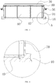
Fig. 3 is a cross-sectional view of a battery pack according to an embodiment of the present disclosure; and -
Fig. 4 is a local enlarged view of portion A inFig. 3 . -
- 10-housing;
- 20-battery pack cover;
- 30-battery monitoring unit;
- 40-structural adhesive;
- 50-sealing ring;
- 60-cell;
- 70-mounting bolt;
- 80-cell fixing board.
- The drawings are incorporated into the specification and constitute a part thereof, illustrating embodiments conforming to the present disclosure and used together with the specification to explain the principle of the present disclosure.
- The present disclosure will be described in further detail by the following embodiments with reference to the drawings. The "front", "rear", "left", "right", "upper", "lower" used in the context are referring to placements of the battery pack and components thereof shown in the drawings.
- Embodiments of the present disclosure provide a battery pack, as shown in
Fig. 1 . The battery pack includes ahousing 10 and abattery pack cover 20. Thebattery pack cover 20 covers thehousing 10 to form a sealed accommodating space in the interior thereof.Cells 60 are arranged in the accommodating space, and an electrode terminal of thecell 60 is closer to thebattery pack cover 20 than the bottom of the cell. The bottom of thehousing 10 is filled with astructural adhesive 40. The battery pack can further include acell fixing board 80, an insulation tray and asealing ring 50. For convenience of monitoring a state of the entire battery pack (including monitoring electric quantity, temperature etc.), abattery monitoring unit 30 can also be mounted to thehousing 10. - The bottom of the
housing 10 has through-holes defined therein along the circumference, as shown inFig. 1 , for mounting of other external components to the battery pack. Thehousing 10 can be connected to thebattery pack cover 20 through bolt connection or clamping connection. - As shown in
Figs. 2-4 , astructural adhesive 40 is used for fixing thecells 60. To be specific, a plurality ofcells 60 are arranged in the interior of ahousing 10, thestructural adhesive 40 is filled between the bottom of thehousing 10 and thecells 60, and thecells 60 are adhered to thehousing 10 through thestructural adhesive 40. Thestructural adhesive 40 can also be filled betweenadjacent cells 60, so that side walls of twoadjacent cells 60 are adhered by thestructural adhesive 40. Meanwhile the structural adhesive 40 between the bottom of thehousing 10 and thecells 60 and thestructural adhesive 40 betweenadjacent cells 60 can be in an integrated structure, so as to further fix thecells 60. - In the above embodiment, the
cells 60 are arranged in the interior of thehousing 10, and thehousing 10 is adhered to thecells 60 through thestructural adhesive 40. Since the structural adhesive 40 functions to fix thecells 60, the frame structure of the module can be omitted, so that the number of components in the battery pack can be reduced, thereby saving manufacture process, improving assembling efficiency, and lowering manufacture cost. In addition, the conventional battery module generally has a height greater than the cell, and thus the height of the battery pack may be increased accordingly. However, in the present disclosure, since no module is needed, the height of the battery pack can be lowered, thereby increasing the volume energy density ratio. - The number of the
cells 60 can be determined based on actual power requirements, and can be one, two, three, four or more. - The
structural adhesive 40 can be a thermal conductive structural adhesive, and also can be a normal adhesive. Thestructural adhesive 40 can be a solid adhesive or a liquid adhesive. Preferably, the abovestructural adhesive 40 is a thermal conductive structural adhesive. The thermal conductive structural adhesive can achieve both the functions of fixing thecells 60 and thermal conduction. In particular, in the solution in which thestructural adhesive 40 is filled between twoadjacent cells 60, a larger amount of heat will accumulate at side walls of thecells 60 after thecells 60 are arranged in thehousing 10. According to the present disclosure, the side walls ofadjacent cells 60 are adhered by the thermal conductive structural adhesive, and the thermal conductive structural adhesive between the side walls of thecells 60 and the thermal conductive structural adhesive for adhering thecells 60 to thehousing 10 are in an integrated structure. This can better transfer the heat of thecells 60 to thehousing 10 while reducing thermal conductive medium, thereby improving heat dissipation efficiency. - The thermal conductive structural adhesive can be a solid adhesive, or can also be a liquid adhesive, which is preferable. Due to the fluidity of the liquid adhesive, when the
cells 60 are arranged in thehousing 10, a tighter contact between thecells 60 and thehousing 10 can be achieved, so that the thermal conductive structural adhesive can be distributed more uniform to obtain better thermal conduction effect, thereby achieving the better temperature uniformity of thecells 60 and thus improving service life of thecells 60. - The thermal conductive structural adhesive contains a silica gel, and thus it can both fix the structure and act as a good thermal conductive medium. The thermal conductive structural adhesive can have a height not greater than one-sixth of a height of the
cell 60. The height of the thermal conductive structural adhesive can be one-sixth, one-seventh or less of the height of thecell 60, so as to ensure the energy density ratio. The height of the thermal conductive structural adhesive can be greater than one-sixth of the height of thecell 60, for example, one-fourth or more of the height of thecell 60.
acell fixing board 80 is connected to thehousing 10 and located in the interior of the accommodating space, and is used to further fix thecell 60. Thecell fixing board 80 is pressed on thecell 60, and thecell 60 is located between thehousing 10 and thecell fixing board 80. Thecell fixing board 80 can be provided with an electrode hole, and when thecell fixing board 80 is pressed on thecell 60, an electrode of thecell 60 will protrudes out of the electrode hole for further assembling and connection. - The connection between the
housing 10 and thecell fixing board 80 can be clamping connection, riveting or bolt connection. As a preferable option, thehousing 10 and thecell fixing board 80 can be connected through a mountingbolt 70. That is, the mountingbolt 70 successively penetrates through thecell fixing board 80 and thestructural adhesive 40 in turn, and then gets into a bolt connection with thehousing 10. Penetrating the mounting bolt through thestructural adhesive 40 can achieve more reliable fixation of thecell 60. - A sealing
ring 50 is used for preventing electrolyte from leaking to the outside of the battery pack and preventing liquid, dust and the like from entering into the battery pack. The sealingring 50 can be made as a circular ring, or can be made as a sealing strip. The sealingring 50 is arranged along the circumference of thehousing 10 and located between thebattery pack cover 20 and thehousing 10, and is tightly pressed between thebattery pack cover 20 and thehousing 10. - The insulation tray is located between the
housing 10 and thecells 60, and is provided with a tray adhesive channel. Thestructural adhesive 40 protrudes through the tray adhesive channel and achieves adhesion to thehousing 10 and thecells 60, respectively. Such a structure can insulate thecells 60 from thehousing 10. - Specifically, the insulation tray can be provided with a separating board located between adjacent cells. The separating board is provided with a separating board adhesive channel, through which the
structural adhesive 40 protrudes to adhere tocells 60 at two sides thereof. Such a structure can achieve the function of insulatingadjacent cells 60. - The insulation tray and the separating board can be in a mesh-shaped structure, in which the tray adhesive channel and the separating board adhesive channel are meshes of the mesh-shaped structure. The insulation tray and the separating board can be in a sponge structure, in which the tray adhesive channel and the separating board adhesive channel are flocculent holes of the sponge structure. The insulation tray and the separating board can be in a flat-plate structure, in which the tray adhesive channel and the separating board adhesive channel are through holes distributed in the flat plate.
- In an embodiment of the battery pack without the insulation tray, the following assembling method is adopted.
- The first step is to pour a certain amount of structural adhesive 40 into the interior of a
housing 10 in such a manner that thestructural adhesive 40 is uniformly spread over the bottom of thehousing 10. In order to guarantee the volume energy density ratio, the height of thestructural adhesive 40 is preferably no greater than one-sixth of the height of acell 60. - The second step is to, before the
structural adhesive 40 is solidified, arrange a certain number ofcells 60 in the interior of thehousing 10 in such a manner that thestructural adhesive 40 is placed between thecells 60 and thehousing 10, and that after thestructural adhesive 40 is solidified, thecells 60 and thehousing 10 are directly adhered through thestructural adhesive 40. Thecells 60 can be arranged separately in thehousing 10, or can be arranged in thehousing 10 after being packed. - The third step is to, before the
structural adhesive 40 is solidified, tightly press acell fixing board 80 onto thecells 60, and penetrate a mountingbolt 70 through thecell fixing board 80 and thestructural adhesive 40 in turn and then connect it to the bottom of thehousing 10, so as to fasten thecell fixing board 80 to thehousing 10. Specifically, the mountingbolt 70 is tightly threaded into a corresponding threaded hole of thehousing 10 before thestructural adhesive 40 is solidified, so that when thestructural adhesive 40 is solidified, the mountingbolt 70 is also adhered to thestructural adhesive 40. This can achieve the more reliable fixation of thecells 60. - The fourth step is to mount the
cell monitoring unit 30 into thehousing 10, place a sealingring 50 on thehousing 10, cover thebattery pack cover 20 on thehousing 10, and tightly press the sealingring 50 by fastening the battery pack cover 20 with thehousing 10. - In an embodiment of the battery pack having the insulation tray with a separating board, the following assembling method is adopted.
- The first step is to place the insulation tray having the separating board in the bottom of a
housing 10. - The second step is to arrange a certain number of
cells 60 in the interior of thehousing 10 in such a manner that the insulation tray is placed between thecells 60 and thehousing 10 and the separating board is located betweenadjacent cells 60. Thecells 60 can be arranged separately in thehousing 10, or can be arranged in thehousing 10 after being packed. - The third step is to tightly press the
cell fixing board 80 onto thecells 60. - The fourth step is to pour a certain amount of structural adhesive 40 into the interior of the
housing 10 in such a manner that thestructural adhesive 40 is uniformly spread over the bottom of thehousing 10. In order to guarantee the volume energy density ratio, the height of thestructural adhesive 40 is preferably no greater than one-sixth of the height of thecell 60. - The fifth step is to, before the
structural adhesive 40 is solidified, penetrate a mountingbolt 70 through thecell fixing board 80 and thestructural adhesive 40 in turn and then connect it to the bottom of thehousing 10, so as to fasten thecell fixing board 80 to thehousing 10. Specifically, the mountingbolt 70 is tightly threaded into a corresponding threaded hole of thehousing 10 before thestructural adhesive 40 is solidified, so that when thestructural adhesive 40 is solidified, the mountingbolt 70 is also adhered to thestructural adhesive 40. This can achieve the more reliable fixation of thecells 60. - The sixth step is to mount a
cell monitoring unit 30 into thehousing 10, place a sealingring 50 on thehousing 10, cover abattery pack cover 20 on thehousing 10, and tightly press the sealingring 50 by fastening the battery pack cover 20 with thehousing 10. - The above are only preferred embodiments of the present disclosure, which shall not be interpreted as constituting limitations thereto. For those skilled in the art, the present disclosure can have various modifications and alternations. Any modifications, equivalent substitutions and improvements made within the principle of the present disclosure shall be regarded as falling into the protection scope of the present disclosure.
Claims (10)
- A battery pack, comprising a housing (10), characterized in that a plurality of cells (60) is arranged in interior of the housing (10), a structural adhesive (40) is filled between a bottom of the housing (10) and the plurality of cells (60), and the plurality of cells (60) is adhered to the housing (10) through the structural adhesive (40).
- The battery pack according to claim 1, characterized in that another structural adhesive (40) is filled between adjacent cells (60) of the plurality of cells (60), and the adjacent cells (60) are adhered to each other by the another structural adhesive (40); the structural adhesive (40) between the bottom of the housing (10) and the plurality of cells (60) and the another structural adhesive (40) between the adjacent cells (60) of the plurality of cells (60) are in an integrated structure.
- The battery pack according to claim 1, characterized in that the battery pack further comprises a cell fixing board (80) connected to the housing (10), wherein the cell fixing board (80) is pressed onto the plurality of cells (60), and the plurality of cells (60) is arranged between the housing (10) and the cell fixing board (80).
- The battery pack according to claim 3, characterized in that the battery pack further comprises a mounting bolt (70) penetrating through the cell fixing board and the structural adhesive in turn, and the mounting bolt (70) is screwed with the housing (10).
- The battery pack according to claim 3, characterized in that the cell fixing board (80) has an electrode hole, and an electrode of the cell (60) protrudes out of the electrode hole.
- The battery pack according to any one of claims 1-5, characterized in that the structural adhesive (40) is a thermal conductive structural adhesive (40).
- The battery pack according to claim 6, characterized in that the thermal conductive structural adhesive (40) is a liquid adhesive.
- The battery pack according to claim 6, characterized in that the thermal conductive structural adhesive (40) has a height no greater than one-sixth of a height of each of the plurality of cells (60).
- The battery pack according to claim 6, characterized in that the battery pack further comprises an insulation tray located between the housing (10) and the plurality of cells (60), wherein the insulation tray has a tray adhesive channel, and the structural adhesive (40) protrudes through the tray adhesive channel and adheres to the housing (10) and the plurality of cells (60), respectively.
- The battery pack according to claim 9, characterized in that the insulation tray comprises a separating board located between adjacent cells (60) of the plurality of cells (60), the separating board has a separating board adhesive channel, and the structural adhesive (40) protrudes through the separating board adhesive channel and adheres to the cells (60) at two sides of the separating board adhesive channel, respectively.
Applications Claiming Priority (2)
| Application Number | Priority Date | Filing Date | Title |
|---|---|---|---|
| CN201610339171.6A CN105762316A (en) | 2016-05-20 | 2016-05-20 | Battery box |
| PCT/CN2017/080440 WO2017198017A1 (en) | 2016-05-20 | 2017-04-13 | Battery box |
Publications (3)
| Publication Number | Publication Date |
|---|---|
| EP3460867A1 true EP3460867A1 (en) | 2019-03-27 |
| EP3460867A4 EP3460867A4 (en) | 2020-04-01 |
| EP3460867B1 EP3460867B1 (en) | 2025-11-19 |
Family
ID=56324354
Family Applications (1)
| Application Number | Title | Priority Date | Filing Date |
|---|---|---|---|
| EP17798581.9A Active EP3460867B1 (en) | 2016-05-20 | 2017-04-13 | Battery box |
Country Status (6)
| Country | Link |
|---|---|
| US (3) | US11005131B2 (en) |
| EP (1) | EP3460867B1 (en) |
| CN (1) | CN105762316A (en) |
| ES (1) | ES3060766T3 (en) |
| PL (1) | PL3460867T3 (en) |
| WO (1) | WO2017198017A1 (en) |
Cited By (2)
| Publication number | Priority date | Publication date | Assignee | Title |
|---|---|---|---|---|
| EP3736879A1 (en) * | 2019-05-07 | 2020-11-11 | Contemporary Amperex Technology Co., Limited | Battery pack and vehicle |
| WO2021098440A1 (en) | 2019-11-18 | 2021-05-27 | 比亚迪股份有限公司 | Battery pack and electric vehicle |
Families Citing this family (53)
| Publication number | Priority date | Publication date | Assignee | Title |
|---|---|---|---|---|
| CN105762316A (en) * | 2016-05-20 | 2016-07-13 | 宁德时代新能源科技股份有限公司 | Battery box |
| DE102016217895A1 (en) * | 2016-09-19 | 2018-03-22 | Audi Ag | Energy storage device for a motor vehicle, motor vehicle and method for producing an energy storage device |
| CN107046111A (en) * | 2017-01-20 | 2017-08-15 | 惠州市亿能电子有限公司 | A kind of battery system and its production technology with entity structure |
| DE102017104711A1 (en) * | 2017-03-07 | 2018-09-13 | Dr. Ing. H.C. F. Porsche Aktiengesellschaft | Automotive high-voltage energy storage |
| CN107146868B (en) * | 2017-06-29 | 2023-07-21 | 绵阳启创电子科技有限公司 | Battery cell module, vehicle battery and motor vehicle |
| CN108777268A (en) * | 2018-04-19 | 2018-11-09 | 芜湖天量电池系统有限公司 | A kind of novel power battery pack arrangement and its packaging technology |
| CN108923008B (en) * | 2018-08-21 | 2024-08-20 | 广东亿鑫丰智能装备股份有限公司 | Improved liquid cooling battery box |
| US12410300B2 (en) | 2018-10-12 | 2025-09-09 | Ppg Industries Ohio, Inc. | Compositions containing thermally conductive fillers |
| CN111063959A (en) * | 2018-10-17 | 2020-04-24 | 郑州深澜动力科技有限公司 | Electric vehicle and its battery module |
| USD933590S1 (en) * | 2018-11-27 | 2021-10-19 | Hongzhang Chen | Battery box |
| CN109449338B (en) * | 2018-12-10 | 2024-05-07 | 广州市垠瀚能源科技有限公司 | A battery core fixing structure of electric vehicle and electric vehicle |
| CN109686883A (en) * | 2018-12-24 | 2019-04-26 | 珠海银隆电器有限公司 | Battery case mould group production method, system and battery case mould group |
| CN110190211B (en) | 2018-12-29 | 2020-03-31 | 比亚迪股份有限公司 | Battery tray, power battery package and vehicle |
| CN111384337B (en) * | 2018-12-29 | 2021-05-04 | 宁德时代新能源科技股份有限公司 | battery box |
| CN111384328A (en) | 2018-12-29 | 2020-07-07 | 比亚迪股份有限公司 | Battery trays, power battery packs and vehicles |
| CN111384314B (en) * | 2018-12-29 | 2021-01-19 | 宁德时代新能源科技股份有限公司 | Battery box |
| HUE061756T2 (en) | 2019-01-09 | 2023-08-28 | Byd Co Ltd | Single cell, power battery pack, and electric vehicle |
| USD883196S1 (en) * | 2019-01-22 | 2020-05-05 | Xingze Chen | Battery case |
| USD890087S1 (en) * | 2019-01-30 | 2020-07-14 | Quan Xiao | Battery box for christmas string lights |
| USD909962S1 (en) * | 2019-02-20 | 2021-02-09 | Lg Electronics Inc. | Battery case for air purifier |
| DE102019112219A1 (en) * | 2019-05-10 | 2020-11-12 | Johnson Controls Autobatterie Gmbh & Co. Kgaa | Battery case and battery with such |
| CN112117397A (en) * | 2019-06-21 | 2020-12-22 | 比亚迪股份有限公司 | Battery pack and vehicle |
| CN112117400A (en) * | 2019-06-21 | 2020-12-22 | 比亚迪股份有限公司 | Power battery package and vehicle |
| CN112133851A (en) * | 2019-06-25 | 2020-12-25 | 比亚迪股份有限公司 | Battery pack and vehicle with same |
| CN110474005A (en) * | 2019-09-06 | 2019-11-19 | 荣盛盟固利新能源科技有限公司 | Lithium battery temperature management case and lithium battery system |
| CN110767858B (en) * | 2019-11-04 | 2022-11-22 | 华霆(合肥)动力技术有限公司 | Battery pack and electric vehicle |
| US12630740B2 (en) | 2019-12-11 | 2026-05-19 | Ppg Industries Ohio, Inc. | Compositions containing thermally conductive fillers |
| KR102952072B1 (en) * | 2020-02-25 | 2026-04-10 | 삼성에스디아이 주식회사 | Battery pack |
| JP7454411B2 (en) * | 2020-03-04 | 2024-03-22 | 三洋電機株式会社 | battery pack |
| CN113540661A (en) * | 2020-03-31 | 2021-10-22 | 比亚迪股份有限公司 | Battery pack and electronic device |
| CN111599957A (en) * | 2020-04-27 | 2020-08-28 | 威睿电动汽车技术(宁波)有限公司 | Battery module and battery pack |
| CN113764786B (en) * | 2020-05-18 | 2022-10-18 | 比亚迪股份有限公司 | Battery, battery pack and automobile |
| CN111987272B (en) * | 2020-09-04 | 2021-04-23 | 江苏塔菲尔动力系统有限公司 | A battery pack with liquid cooling on the battery side |
| CN112510301B (en) * | 2020-11-30 | 2023-03-24 | 湖南海博瑞德电智控制技术有限公司 | Battery system |
| DE102021002803A1 (en) * | 2021-05-31 | 2021-07-15 | Daimler Ag | Battery arrangement for a motor vehicle |
| CN113708002A (en) * | 2021-09-29 | 2021-11-26 | 远景能源有限公司 | Battery box and energy storage battery |
| CN114284643A (en) * | 2021-12-17 | 2022-04-05 | 上海瑞浦青创新能源有限公司 | Multi-row module structure |
| JP7624419B2 (en) | 2022-01-24 | 2025-01-30 | プライムプラネットエナジー&ソリューションズ株式会社 | Battery pack |
| US12275298B2 (en) | 2022-03-23 | 2025-04-15 | Ford Global Technologies, Llc | Traction battery packs with cell-to-pack battery systems housed within irregularly shaped enclosures |
| US12230826B2 (en) | 2022-03-23 | 2025-02-18 | Ford Global Technologies, Llc | Methods for assembling traction battery packs |
| US12506215B2 (en) | 2022-03-23 | 2025-12-23 | Ford Global Technologies, Llc | Enclosure cover attachment configurations for traction battery packs with cell-to-pack battery systems |
| US12525637B2 (en) | 2022-03-23 | 2026-01-13 | Ford Global Technologies, Llc | Traction battery pack assembling method |
| US20230307766A1 (en) * | 2022-03-23 | 2023-09-28 | Ford Global Technologies, Llc | Traction battery pack assembly method |
| US12567642B2 (en) | 2022-03-23 | 2026-03-03 | Ford Global Technologies, Llc | Shim systems for traction battery packs |
| US12651799B2 (en) | 2022-03-23 | 2026-06-09 | Ford Global Technologies, Llc | Traction battery pack assembling method |
| US12424695B2 (en) | 2022-03-23 | 2025-09-23 | Ford Global Technologies, Llc | Retention assemblies for traction battery packs with cell-to-pack battery systems |
| US12374750B2 (en) | 2022-03-23 | 2025-07-29 | Ford Global Technologies, Llc | Traction battery pack assembling method |
| US12479327B2 (en) | 2022-03-23 | 2025-11-25 | Ford Global Technologies, Llc | Traction battery pack cell stack removal method and battery pack assembly |
| US12603373B2 (en) | 2022-03-23 | 2026-04-14 | Ford Global Technologies, Llc | Traction battery pack assembling method |
| US12633564B2 (en) | 2022-03-23 | 2026-05-19 | Ford Global Technologies, Llc | Battery lift and transfer solutions for assembling traction battery packs |
| WO2024021064A1 (en) * | 2022-07-29 | 2024-02-01 | 宁德时代新能源科技股份有限公司 | Battery and electric device |
| KR20250132888A (en) * | 2024-02-29 | 2025-09-05 | 주식회사 엘지에너지솔루션 | Battery pack case, battery pack, and battery device comprising the same |
| KR20260109346A (en) * | 2025-01-03 | 2026-07-10 | 삼성에스디아이 주식회사 | Battery module |
Family Cites Families (23)
| Publication number | Priority date | Publication date | Assignee | Title |
|---|---|---|---|---|
| US5432017A (en) * | 1992-09-14 | 1995-07-11 | Motorola, Inc. | Battery pack and method of forming same |
| US5601942A (en) * | 1993-08-31 | 1997-02-11 | Vst Technologies, Inc. | Portable battery pack apparatus and method of fabrication thereof |
| JPH10284024A (en) | 1997-04-07 | 1998-10-23 | Toshiba Corp | Battery pack |
| US6232013B1 (en) | 1997-11-26 | 2001-05-15 | Lucent Technologies Inc. | Droppable battery packs |
| US8263244B2 (en) * | 2008-04-18 | 2012-09-11 | Cobasys, Llc | Isolation tray for a battery system |
| US8216502B2 (en) * | 2008-12-02 | 2012-07-10 | Tesla Motors, Inc. | Method for the external application of battery pack encapsulant |
| JP5542544B2 (en) * | 2010-06-28 | 2014-07-09 | 日立ビークルエナジー株式会社 | Power storage module and power storage device |
| CN102447133B (en) * | 2010-10-12 | 2015-10-21 | 深圳市比克电池有限公司 | A kind of vehicle lithium-ion power battery |
| CN102956787A (en) * | 2011-08-16 | 2013-03-06 | 欧司朗股份有限公司 | Electronic module, light emitting device and manufacture method of electronic module |
| CN202871893U (en) * | 2012-10-17 | 2013-04-10 | 周仕元 | Anti-explosion cooling device for lithium-ion battery pack |
| US20140154539A1 (en) * | 2012-12-05 | 2014-06-05 | Caterpillar Inc. | Module for securing energy storage cells |
| US9837651B2 (en) * | 2013-06-27 | 2017-12-05 | Ying-Tsun Lin | Electric core for thin film battery |
| US20180258329A1 (en) * | 2015-09-10 | 2018-09-13 | Dow Global Technologies Llc | High modulus, toughened one-component epoxy structural adhesives with high aspect ratio fillers |
| EP3358640B1 (en) * | 2015-09-29 | 2025-04-09 | GS Yuasa International Ltd. | Electricity storage device and method for manufacturing electricity storage device |
| JP6577375B2 (en) * | 2016-01-19 | 2019-09-18 | カルソニックカンセイ株式会社 | Assembled battery and method of manufacturing the assembled battery |
| CN105702892B (en) | 2016-02-02 | 2019-05-24 | 北方奥钛纳米技术有限公司 | A thermally conductive battery box |
| CN105720220B (en) * | 2016-04-18 | 2018-08-07 | 力帆实业(集团)股份有限公司 | A kind of electric automobile power battery |
| CN205645963U (en) | 2016-04-18 | 2016-10-12 | 重庆无线绿洲通信技术有限公司 | Electric automobile modularization quick change power battery unit |
| CN105762316A (en) * | 2016-05-20 | 2016-07-13 | 宁德时代新能源科技股份有限公司 | Battery box |
| CN205900600U (en) | 2016-07-19 | 2017-01-18 | 成都硅宝科技股份有限公司 | Safety battery group |
| CN205900709U (en) | 2016-07-26 | 2017-01-18 | 北京长城华冠汽车科技股份有限公司 | Power battery and have this power battery's vehicle |
| CN106299166B (en) | 2016-09-20 | 2020-02-11 | 宁德时代新能源科技股份有限公司 | Battery pack |
| CN106450089B (en) * | 2016-11-09 | 2023-02-28 | 安徽天鑫能源科技有限公司 | Non-modular battery pack structure |
-
2016
- 2016-05-20 CN CN201610339171.6A patent/CN105762316A/en active Pending
-
2017
- 2017-04-13 WO PCT/CN2017/080440 patent/WO2017198017A1/en not_active Ceased
- 2017-04-13 PL PL17798581.9T patent/PL3460867T3/en unknown
- 2017-04-13 ES ES17798581T patent/ES3060766T3/en active Active
- 2017-04-13 EP EP17798581.9A patent/EP3460867B1/en active Active
- 2017-04-13 US US16/303,425 patent/US11005131B2/en active Active
-
2021
- 2021-04-02 US US17/220,929 patent/US11289750B2/en active Active
-
2022
- 2022-02-16 US US17/673,720 patent/US11600871B2/en active Active
Cited By (5)
| Publication number | Priority date | Publication date | Assignee | Title |
|---|---|---|---|---|
| EP3736879A1 (en) * | 2019-05-07 | 2020-11-11 | Contemporary Amperex Technology Co., Limited | Battery pack and vehicle |
| US11101515B2 (en) | 2019-05-07 | 2021-08-24 | Contemporary Amperex Technology Co., Limited | Battery pack and vehicle |
| US11133549B2 (en) | 2019-05-07 | 2021-09-28 | Contemporary Amperex Technology Co., Limited | Battery pack and vehicle |
| WO2021098440A1 (en) | 2019-11-18 | 2021-05-27 | 比亚迪股份有限公司 | Battery pack and electric vehicle |
| US12230821B2 (en) | 2019-11-18 | 2025-02-18 | Byd Company Limited | Battery pack and electric vehicle |
Also Published As
| Publication number | Publication date |
|---|---|
| US20220216536A1 (en) | 2022-07-07 |
| US11600871B2 (en) | 2023-03-07 |
| CN105762316A (en) | 2016-07-13 |
| US11005131B2 (en) | 2021-05-11 |
| US20210226278A1 (en) | 2021-07-22 |
| ES3060766T3 (en) | 2026-03-30 |
| PL3460867T3 (en) | 2026-04-07 |
| US20190326565A1 (en) | 2019-10-24 |
| EP3460867A4 (en) | 2020-04-01 |
| US11289750B2 (en) | 2022-03-29 |
| WO2017198017A1 (en) | 2017-11-23 |
| EP3460867B1 (en) | 2025-11-19 |
Similar Documents
| Publication | Publication Date | Title |
|---|---|---|
| US11600871B2 (en) | Battery pack | |
| CN216389618U (en) | Battery pack and vehicle | |
| CN222380668U (en) | Battery cell, battery pack and vehicle | |
| CN204303901U (en) | Battery pole ear syndeton and comprise the flexible-packed battery module of this syndeton | |
| CN209592168U (en) | Battery module, battery system and electric vehicle with the battery module | |
| CN223414189U (en) | Energy storage power supply | |
| CN108933296B (en) | Lithium-ion battery pack | |
| CN210040348U (en) | Battery module and power battery | |
| CN214378624U (en) | Battery connection piece mounting structure, battery module and battery | |
| CN209312824U (en) | A kind of integral housing battery modules | |
| CN211404560U (en) | Flexible package polymer lithium battery pack with improved structure | |
| CN211208504U (en) | battery module | |
| CN114421072B (en) | Energy storage equipment | |
| CN209592167U (en) | Battery modules and battery system and electric vehicle with the battery modules | |
| CN216720128U (en) | Laminate polymer battery package and electric automobile | |
| CN216529184U (en) | Battery module and battery pack | |
| CN112290141A (en) | A module assembly structure for a battery pack | |
| CN223583087U (en) | A soft-pack battery module and battery pack | |
| CN218632352U (en) | A battery cell mechanism, a battery cell assembly, and an electric vehicle | |
| CN218123554U (en) | Battery pack with heat dissipation structure | |
| CN223273453U (en) | Energy storage power supply | |
| CN223728869U (en) | Cell cover assembly and cell structure | |
| CN222089952U (en) | Battery device, electric control box and electric device | |
| CN217361812U (en) | Box-packed lithium battery with strong heat dissipation performance | |
| CN223828504U (en) | Battery box and vehicle comprising same |
Legal Events
| Date | Code | Title | Description |
|---|---|---|---|
| STAA | Information on the status of an ep patent application or granted ep patent |
Free format text: STATUS: THE INTERNATIONAL PUBLICATION HAS BEEN MADE |
|
| PUAI | Public reference made under article 153(3) epc to a published international application that has entered the european phase |
Free format text: ORIGINAL CODE: 0009012 |
|
| STAA | Information on the status of an ep patent application or granted ep patent |
Free format text: STATUS: REQUEST FOR EXAMINATION WAS MADE |
|
| 17P | Request for examination filed |
Effective date: 20181220 |
|
| AK | Designated contracting states |
Kind code of ref document: A1 Designated state(s): AL AT BE BG CH CY CZ DE DK EE ES FI FR GB GR HR HU IE IS IT LI LT LU LV MC MK MT NL NO PL PT RO RS SE SI SK SM TR |
|
| AX | Request for extension of the european patent |
Extension state: BA ME |
|
| DAV | Request for validation of the european patent (deleted) | ||
| DAX | Request for extension of the european patent (deleted) | ||
| A4 | Supplementary search report drawn up and despatched |
Effective date: 20200227 |
|
| RIC1 | Information provided on ipc code assigned before grant |
Ipc: H01M 10/60 20140101ALI20200222BHEP Ipc: H01M 2/02 20060101AFI20200222BHEP Ipc: H01M 2/10 20060101ALI20200222BHEP |
|
| STAA | Information on the status of an ep patent application or granted ep patent |
Free format text: STATUS: EXAMINATION IS IN PROGRESS |
|
| 17Q | First examination report despatched |
Effective date: 20230125 |
|
| RAP1 | Party data changed (applicant data changed or rights of an application transferred) |
Owner name: CONTEMPORARY AMPEREX TECHNOLOGY(HONG KONG) LIMITED |
|
| REG | Reference to a national code |
Ref country code: DE Ref legal event code: R079 Free format text: PREVIOUS MAIN CLASS: H01M0002020000 Ipc: H01M0010600000 Ref country code: DE Ref legal event code: R079 Ref document number: 602017092808 Country of ref document: DE Free format text: PREVIOUS MAIN CLASS: H01M0002020000 Ipc: H01M0010600000 |
|
| GRAP | Despatch of communication of intention to grant a patent |
Free format text: ORIGINAL CODE: EPIDOSNIGR1 |
|
| STAA | Information on the status of an ep patent application or granted ep patent |
Free format text: STATUS: GRANT OF PATENT IS INTENDED |
|
| RIC1 | Information provided on ipc code assigned before grant |
Ipc: H01M 10/60 20140101AFI20250704BHEP Ipc: H01M 50/209 20210101ALI20250704BHEP Ipc: H01M 50/249 20210101ALI20250704BHEP Ipc: H01M 50/103 20210101ALI20250704BHEP Ipc: H01M 50/264 20210101ALI20250704BHEP Ipc: H01M 50/271 20210101ALI20250704BHEP Ipc: H01M 50/289 20210101ALI20250704BHEP Ipc: H01M 10/613 20140101ALI20250704BHEP Ipc: H01M 10/647 20140101ALI20250704BHEP Ipc: H01M 10/653 20140101ALI20250704BHEP |
|
| INTG | Intention to grant announced |
Effective date: 20250807 |
|
| GRAS | Grant fee paid |
Free format text: ORIGINAL CODE: EPIDOSNIGR3 |
|
| GRAA | (expected) grant |
Free format text: ORIGINAL CODE: 0009210 |
|
| STAA | Information on the status of an ep patent application or granted ep patent |
Free format text: STATUS: THE PATENT HAS BEEN GRANTED |
|
| AK | Designated contracting states |
Kind code of ref document: B1 Designated state(s): AL AT BE BG CH CY CZ DE DK EE ES FI FR GB GR HR HU IE IS IT LI LT LU LV MC MK MT NL NO PL PT RO RS SE SI SK SM TR |
|
| REG | Reference to a national code |
Ref country code: CH Ref legal event code: F10 Free format text: ST27 STATUS EVENT CODE: U-0-0-F10-F00 (AS PROVIDED BY THE NATIONAL OFFICE) Effective date: 20251119 Ref country code: GB Ref legal event code: FG4D |
|
| REG | Reference to a national code |
Ref country code: DE Ref legal event code: R096 Ref document number: 602017092808 Country of ref document: DE |
|
| REG | Reference to a national code |
Ref country code: IE Ref legal event code: FG4D |
|
| REG | Reference to a national code |
Ref country code: NL Ref legal event code: FP |
|
| P01 | Opt-out of the competence of the unified patent court (upc) registered |
Free format text: CASE NUMBER: UPC_APP_0003305_3460867/2026 Effective date: 20260129 |
|
| REG | Reference to a national code |
Ref country code: ES Ref legal event code: FG2A Ref document number: 3060766 Country of ref document: ES Kind code of ref document: T3 Effective date: 20260330 |
|
| PGFP | Annual fee paid to national office [announced via postgrant information from national office to epo] |
Ref country code: GB Payment date: 20260327 Year of fee payment: 10 |
|
| REG | Reference to a national code |
Ref country code: LT Ref legal event code: MG9D |
|
| PG25 | Lapsed in a contracting state [announced via postgrant information from national office to epo] |
Ref country code: HR Free format text: LAPSE BECAUSE OF FAILURE TO SUBMIT A TRANSLATION OF THE DESCRIPTION OR TO PAY THE FEE WITHIN THE PRESCRIBED TIME-LIMIT Effective date: 20251119 Ref country code: FI Free format text: LAPSE BECAUSE OF FAILURE TO SUBMIT A TRANSLATION OF THE DESCRIPTION OR TO PAY THE FEE WITHIN THE PRESCRIBED TIME-LIMIT Effective date: 20251119 |
|
| PG25 | Lapsed in a contracting state [announced via postgrant information from national office to epo] |
Ref country code: RS Free format text: LAPSE BECAUSE OF FAILURE TO SUBMIT A TRANSLATION OF THE DESCRIPTION OR TO PAY THE FEE WITHIN THE PRESCRIBED TIME-LIMIT Effective date: 20260219 |
|
| PG25 | Lapsed in a contracting state [announced via postgrant information from national office to epo] |
Ref country code: IS Free format text: LAPSE BECAUSE OF FAILURE TO SUBMIT A TRANSLATION OF THE DESCRIPTION OR TO PAY THE FEE WITHIN THE PRESCRIBED TIME-LIMIT Effective date: 20260319 |
|
| PG25 | Lapsed in a contracting state [announced via postgrant information from national office to epo] |
Ref country code: PT Free format text: LAPSE BECAUSE OF FAILURE TO SUBMIT A TRANSLATION OF THE DESCRIPTION OR TO PAY THE FEE WITHIN THE PRESCRIBED TIME-LIMIT Effective date: 20260319 |
|
| PG25 | Lapsed in a contracting state [announced via postgrant information from national office to epo] |
Ref country code: LV Free format text: LAPSE BECAUSE OF FAILURE TO SUBMIT A TRANSLATION OF THE DESCRIPTION OR TO PAY THE FEE WITHIN THE PRESCRIBED TIME-LIMIT Effective date: 20251119 |
|
| PG25 | Lapsed in a contracting state [announced via postgrant information from national office to epo] |
Ref country code: BG Free format text: LAPSE BECAUSE OF FAILURE TO SUBMIT A TRANSLATION OF THE DESCRIPTION OR TO PAY THE FEE WITHIN THE PRESCRIBED TIME-LIMIT Effective date: 20251119 |
|
| PGFP | Annual fee paid to national office [announced via postgrant information from national office to epo] |
Ref country code: NL Payment date: 20260420 Year of fee payment: 10 |
|
| PGFP | Annual fee paid to national office [announced via postgrant information from national office to epo] |
Ref country code: HU Payment date: 20260417 Year of fee payment: 10 |
|
| REG | Reference to a national code |
Ref country code: HU Ref legal event code: AG4A Ref document number: E075668 Country of ref document: HU |
|
| PG25 | Lapsed in a contracting state [announced via postgrant information from national office to epo] |
Ref country code: LT Free format text: LAPSE BECAUSE OF FAILURE TO SUBMIT A TRANSLATION OF THE DESCRIPTION OR TO PAY THE FEE WITHIN THE PRESCRIBED TIME-LIMIT Effective date: 20251119 |
|
| PG25 | Lapsed in a contracting state [announced via postgrant information from national office to epo] |
Ref country code: SM Free format text: LAPSE BECAUSE OF FAILURE TO SUBMIT A TRANSLATION OF THE DESCRIPTION OR TO PAY THE FEE WITHIN THE PRESCRIBED TIME-LIMIT Effective date: 20251119 |
|
| PGFP | Annual fee paid to national office [announced via postgrant information from national office to epo] |
Ref country code: ES Payment date: 20260504 Year of fee payment: 10 |
|
| PG25 | Lapsed in a contracting state [announced via postgrant information from national office to epo] |
Ref country code: DK Free format text: LAPSE BECAUSE OF FAILURE TO SUBMIT A TRANSLATION OF THE DESCRIPTION OR TO PAY THE FEE WITHIN THE PRESCRIBED TIME-LIMIT Effective date: 20251119 |
|
| PGFP | Annual fee paid to national office [announced via postgrant information from national office to epo] |
Ref country code: PL Payment date: 20260401 Year of fee payment: 10 |
|
| PGFP | Annual fee paid to national office [announced via postgrant information from national office to epo] |
Ref country code: IT Payment date: 20260423 Year of fee payment: 10 |
|
| PGFP | Annual fee paid to national office [announced via postgrant information from national office to epo] |
Ref country code: DE Payment date: 20260427 Year of fee payment: 10 |
|
| PGFP | Annual fee paid to national office [announced via postgrant information from national office to epo] |
Ref country code: NO Payment date: 20260423 Year of fee payment: 10 |
|
| PGFP | Annual fee paid to national office [announced via postgrant information from national office to epo] |
Ref country code: SE Payment date: 20260421 Year of fee payment: 10 Ref country code: AT Payment date: 20260423 Year of fee payment: 10 |
|
| PG25 | Lapsed in a contracting state [announced via postgrant information from national office to epo] |
Ref country code: EE Free format text: LAPSE BECAUSE OF FAILURE TO SUBMIT A TRANSLATION OF THE DESCRIPTION OR TO PAY THE FEE WITHIN THE PRESCRIBED TIME-LIMIT Effective date: 20251119 |
|
| PG25 | Lapsed in a contracting state [announced via postgrant information from national office to epo] |
Ref country code: CZ Free format text: LAPSE BECAUSE OF FAILURE TO SUBMIT A TRANSLATION OF THE DESCRIPTION OR TO PAY THE FEE WITHIN THE PRESCRIBED TIME-LIMIT Effective date: 20251119 |
|
| PGFP | Annual fee paid to national office [announced via postgrant information from national office to epo] |
Ref country code: FR Payment date: 20260423 Year of fee payment: 10 |
|
| PG25 | Lapsed in a contracting state [announced via postgrant information from national office to epo] |
Ref country code: SK Free format text: LAPSE BECAUSE OF FAILURE TO SUBMIT A TRANSLATION OF THE DESCRIPTION OR TO PAY THE FEE WITHIN THE PRESCRIBED TIME-LIMIT Effective date: 20251119 |