EP3460581A1 - Image forming apparatus - Google Patents
Image forming apparatus Download PDFInfo
- Publication number
- EP3460581A1 EP3460581A1 EP18195376.1A EP18195376A EP3460581A1 EP 3460581 A1 EP3460581 A1 EP 3460581A1 EP 18195376 A EP18195376 A EP 18195376A EP 3460581 A1 EP3460581 A1 EP 3460581A1
- Authority
- EP
- European Patent Office
- Prior art keywords
- duty ratio
- image
- pixel
- image forming
- forming apparatus
- Prior art date
- Legal status (The legal status is an assumption and is not a legal conclusion. Google has not performed a legal analysis and makes no representation as to the accuracy of the status listed.)
- Granted
Links
Images





Classifications
-
- H—ELECTRICITY
- H04—ELECTRIC COMMUNICATION TECHNIQUE
- H04N—PICTORIAL COMMUNICATION, e.g. TELEVISION
- H04N1/00—Scanning, transmission or reproduction of documents or the like, e.g. facsimile transmission; Details thereof
- H04N1/46—Colour picture communication systems
- H04N1/56—Processing of colour picture signals
- H04N1/60—Colour correction or control
- H04N1/6002—Corrections within particular colour systems
- H04N1/6008—Corrections within particular colour systems with primary colour signals, e.g. RGB or CMY(K)
-
- G—PHYSICS
- G03—PHOTOGRAPHY; CINEMATOGRAPHY; ANALOGOUS TECHNIQUES USING WAVES OTHER THAN OPTICAL WAVES; ELECTROGRAPHY; HOLOGRAPHY
- G03G—ELECTROGRAPHY; ELECTROPHOTOGRAPHY; MAGNETOGRAPHY
- G03G15/00—Apparatus for electrographic processes using a charge pattern
- G03G15/50—Machine control of apparatus for electrographic processes using a charge pattern, e.g. regulating differents parts of the machine, multimode copiers, microprocessor control
-
- G—PHYSICS
- G03—PHOTOGRAPHY; CINEMATOGRAPHY; ANALOGOUS TECHNIQUES USING WAVES OTHER THAN OPTICAL WAVES; ELECTROGRAPHY; HOLOGRAPHY
- G03G—ELECTROGRAPHY; ELECTROPHOTOGRAPHY; MAGNETOGRAPHY
- G03G15/00—Apparatus for electrographic processes using a charge pattern
- G03G15/01—Apparatus for electrographic processes using a charge pattern for producing multicoloured copies
-
- G—PHYSICS
- G03—PHOTOGRAPHY; CINEMATOGRAPHY; ANALOGOUS TECHNIQUES USING WAVES OTHER THAN OPTICAL WAVES; ELECTROGRAPHY; HOLOGRAPHY
- G03G—ELECTROGRAPHY; ELECTROPHOTOGRAPHY; MAGNETOGRAPHY
- G03G15/00—Apparatus for electrographic processes using a charge pattern
- G03G15/01—Apparatus for electrographic processes using a charge pattern for producing multicoloured copies
- G03G15/0105—Details of unit
- G03G15/0121—Details of unit for developing
-
- G—PHYSICS
- G03—PHOTOGRAPHY; CINEMATOGRAPHY; ANALOGOUS TECHNIQUES USING WAVES OTHER THAN OPTICAL WAVES; ELECTROGRAPHY; HOLOGRAPHY
- G03G—ELECTROGRAPHY; ELECTROPHOTOGRAPHY; MAGNETOGRAPHY
- G03G15/00—Apparatus for electrographic processes using a charge pattern
- G03G15/06—Apparatus for electrographic processes using a charge pattern for developing
- G03G15/08—Apparatus for electrographic processes using a charge pattern for developing using a solid developer, e.g. powder developer
- G03G15/0806—Apparatus for electrographic processes using a charge pattern for developing using a solid developer, e.g. powder developer on a donor element, e.g. belt, roller
- G03G15/0808—Apparatus for electrographic processes using a charge pattern for developing using a solid developer, e.g. powder developer on a donor element, e.g. belt, roller characterised by the developer supplying means, e.g. structure of developer supply roller
-
- G—PHYSICS
- G03—PHOTOGRAPHY; CINEMATOGRAPHY; ANALOGOUS TECHNIQUES USING WAVES OTHER THAN OPTICAL WAVES; ELECTROGRAPHY; HOLOGRAPHY
- G03G—ELECTROGRAPHY; ELECTROPHOTOGRAPHY; MAGNETOGRAPHY
- G03G15/00—Apparatus for electrographic processes using a charge pattern
- G03G15/14—Apparatus for electrographic processes using a charge pattern for transferring a pattern to a second base
- G03G15/16—Apparatus for electrographic processes using a charge pattern for transferring a pattern to a second base of a toner pattern, e.g. a powder pattern, e.g. magnetic transfer
- G03G15/1625—Apparatus for electrographic processes using a charge pattern for transferring a pattern to a second base of a toner pattern, e.g. a powder pattern, e.g. magnetic transfer on a base other than paper
-
- G—PHYSICS
- G03—PHOTOGRAPHY; CINEMATOGRAPHY; ANALOGOUS TECHNIQUES USING WAVES OTHER THAN OPTICAL WAVES; ELECTROGRAPHY; HOLOGRAPHY
- G03G—ELECTROGRAPHY; ELECTROPHOTOGRAPHY; MAGNETOGRAPHY
- G03G15/00—Apparatus for electrographic processes using a charge pattern
- G03G15/65—Apparatus which relate to the handling of copy material
- G03G15/6582—Special processing for irreversibly adding or changing the sheet copy material characteristics or its appearance, e.g. stamping, annotation printing, punching
- G03G15/6585—Special processing for irreversibly adding or changing the sheet copy material characteristics or its appearance, e.g. stamping, annotation printing, punching by using non-standard toners, e.g. transparent toner, gloss adding devices
-
- G—PHYSICS
- G06—COMPUTING OR CALCULATING; COUNTING
- G06T—IMAGE DATA PROCESSING OR GENERATION, IN GENERAL
- G06T7/00—Image analysis
- G06T7/90—Determination of colour characteristics
-
- H—ELECTRICITY
- H04—ELECTRIC COMMUNICATION TECHNIQUE
- H04N—PICTORIAL COMMUNICATION, e.g. TELEVISION
- H04N1/00—Scanning, transmission or reproduction of documents or the like, e.g. facsimile transmission; Details thereof
- H04N1/46—Colour picture communication systems
-
- H—ELECTRICITY
- H04—ELECTRIC COMMUNICATION TECHNIQUE
- H04N—PICTORIAL COMMUNICATION, e.g. TELEVISION
- H04N1/00—Scanning, transmission or reproduction of documents or the like, e.g. facsimile transmission; Details thereof
- H04N1/46—Colour picture communication systems
- H04N1/56—Processing of colour picture signals
- H04N1/60—Colour correction or control
- H04N1/6016—Conversion to subtractive colour signals
-
- G—PHYSICS
- G03—PHOTOGRAPHY; CINEMATOGRAPHY; ANALOGOUS TECHNIQUES USING WAVES OTHER THAN OPTICAL WAVES; ELECTROGRAPHY; HOLOGRAPHY
- G03G—ELECTROGRAPHY; ELECTROPHOTOGRAPHY; MAGNETOGRAPHY
- G03G15/00—Apparatus for electrographic processes using a charge pattern
- G03G15/04—Apparatus for electrographic processes using a charge pattern for exposing, i.e. imagewise exposure by optically projecting the original image on a photoconductive recording material
- G03G15/043—Apparatus for electrographic processes using a charge pattern for exposing, i.e. imagewise exposure by optically projecting the original image on a photoconductive recording material with means for controlling illumination or exposure
-
- G—PHYSICS
- G03—PHOTOGRAPHY; CINEMATOGRAPHY; ANALOGOUS TECHNIQUES USING WAVES OTHER THAN OPTICAL WAVES; ELECTROGRAPHY; HOLOGRAPHY
- G03G—ELECTROGRAPHY; ELECTROPHOTOGRAPHY; MAGNETOGRAPHY
- G03G15/00—Apparatus for electrographic processes using a charge pattern
- G03G15/65—Apparatus which relate to the handling of copy material
- G03G15/6588—Apparatus which relate to the handling of copy material characterised by the copy material, e.g. postcards, large copies, multi-layered materials, coloured sheet material
- G03G15/6591—Apparatus which relate to the handling of copy material characterised by the copy material, e.g. postcards, large copies, multi-layered materials, coloured sheet material characterised by the recording material, e.g. plastic material, OHP, ceramics, tiles, textiles
-
- G—PHYSICS
- G03—PHOTOGRAPHY; CINEMATOGRAPHY; ANALOGOUS TECHNIQUES USING WAVES OTHER THAN OPTICAL WAVES; ELECTROGRAPHY; HOLOGRAPHY
- G03G—ELECTROGRAPHY; ELECTROPHOTOGRAPHY; MAGNETOGRAPHY
- G03G2215/00—Apparatus for electrophotographic processes
- G03G2215/00362—Apparatus for electrophotographic processes relating to the copy medium handling
- G03G2215/00443—Copy medium
- G03G2215/00523—Other special types, e.g. tabbed
- G03G2215/00527—Fabrics, e.g. textiles
-
- H—ELECTRICITY
- H04—ELECTRIC COMMUNICATION TECHNIQUE
- H04N—PICTORIAL COMMUNICATION, e.g. TELEVISION
- H04N1/00—Scanning, transmission or reproduction of documents or the like, e.g. facsimile transmission; Details thereof
- H04N1/46—Colour picture communication systems
- H04N1/54—Conversion of colour picture signals to a plurality of signals some of which represent particular mixed colours, e.g. for textile printing
Definitions
- the technology relates to an image forming apparatus that forms an image on a transfer print medium.
- the white toner is used, for example, to reduce an influence of a ground color of a recording print medium on an image, as disclosed in Japanese Unexamined Patent Application Publication No. 2014-216721 , for example.
- a transfer sheet i.e., a transfer print medium
- an image may be formed once on a transfer print medium
- an adhesive may be placed onto an image portion of this transfer print medium with the use of an adhesive sheet, and the image may be transferred onto the T-shirt from the transfer print medium with the use of an iron, for example. Even in this case, it is expected that a high image quality be achieved.
- an image forming apparatus that includes an image processing section and an image forming section.
- the image processing section corrects, on the basis of a plurality of pieces of image data, a pixel value corresponding to an auxiliary color developer in a first pixel and thereby causes a developer amount in the first pixel to fall within a predetermined range.
- the plurality of pieces of image data corresponding to respective developers include one or more basic color developers that configure an image and the auxiliary color developer.
- the developer amount in the first pixel is a total amount of the one or more basic color developers and the auxiliary color developer in the first pixel when the one or more basic color developers and the auxiliary color developer are disposed on each other.
- the image forming section forms an image on a transfer print medium on the basis of the pieces of image data processed by the image processing section.
- FIG. 1 illustrates an example of a configuration of an image forming apparatus, i.e., an image forming apparatus 1, according to an example embodiment of the technology.
- the image forming apparatus 1 may serve as a printer that forms an image on a transfer print medium with the use of an electrophotographic scheme.
- the image forming apparatus 1 may include a pickup roller 11, a print medium feeding roller 12, print medium sensors 13 and 14, a registration roller 15, a print medium sensor 16, a registration roller 17, a print medium sensor 18, four developing units 20, four toner containers 28, four exposure units 29, a transfer section 30, a fixing section 40, a print medium sensor 43, a conveying roller 44, a conveyance path switching section 45, a conveying roller 47, and a discharge roller 48.
- the four developing units 20 may include developing units 20Y, 20M, 20C, and 20W.
- the four toner containers 28 may include toner containers 28Y, 28M, 28C, and 28W.
- the four exposure units 29 may include exposure units 29Y, 29M, 29C, and 29W.
- the aforementioned members may be disposed along a conveyance path 10 through which a transfer print medium 9 is conveyed.
- the pickup roller 11 may pick up the transfer print medium 9 stored in a print medium container 8, one by one, from the uppermost sheet and send out the picked-up transfer print medium 9 into the conveyance path 10.
- the pickup roller 11 may rotate with motive power transmitted from a print medium feeding roller motor 71B, which will be described later.
- the print medium feeding roller 12 may convey, along the conveyance path 10, the transfer print medium 9 fed from the pickup roller 11.
- the print medium feeding roller 12 may rotate with motive power transmitted from the print medium feeding roller motor 71B, which will be described later.
- the print medium sensors 13 and 14 may detect passage of the transfer print medium 9.
- the registration roller 15 may include a pair of rollers disposed with the conveyance path 10 interposed therebetween.
- the registration roller 15 may correct a skew of the fed transfer print medium 9 and convey the transfer print medium 9 along the conveyance path 10.
- the registration roller 15 may rotate with motive power transmitted from a registration roller motor 72B, which will be described later.
- the print medium sensor 16 may detect passage of the transfer print medium 9.
- the registration roller 17 may include a pair of rollers disposed with the conveyance path 10 interposed therebetween.
- the registration roller 17 may correct a skew of the fed transfer print medium 9 and convey the transfer print medium 9 along the conveyance path 10.
- the registration roller 17 may rotate with motive power transmitted from the registration roller motor 72B, which will be described later.
- the print medium sensor 18 may detect passage of the transfer print medium 9.
- the four developing units 20 may form respective toner images.
- the developing unit 20Y may form a yellow (Y) toner image
- the developing unit 20M may form a magenta (M) toner image
- the developing unit 20C may form a cyan (C) toner image
- the developing unit 20W may form a white (W) toner image.
- the four developing units 20 may be disposed in the order of the developing units 20Y, 20M, 20C, and 20W in a conveying direction F of the transfer print medium 9.
- Each of the developing units 20 may be mountable and removable.
- the four toner containers 28 may each contain a toner.
- the toner container 28Y may contain a yellow toner
- the toner container 28M may contain a magenta toner
- the toner container 28C may contain a cyan toner
- the toner container 28W may contain a white toner.
- the four toner containers 28 may each be mountable to and removable from the corresponding one of the four developing units 20.
- FIG. 2 illustrates an example of a configuration of the developing unit 20.
- FIG. 2 depicts the toner container 28 and the exposure unit 29 as well.
- the developing unit 20 may include a photosensitive drum 21, a cleaning blade 22, a charging roller 24, a developing roller 25, a developing blade 26, and a feeding roller 27.
- the photosensitive drum 21 may support an electrostatic latent image on a surface thereof, i.e., on a surface layer portion thereof.
- the photosensitive drum 21 may rotate counterclockwise with motive power transmitted from a photosensitive drum motor 73B, which will be described later.
- the photosensitive drum 21 may be electrically charged by the charging roller 24 and submitted to exposure by the exposure unit 29.
- the photosensitive drum 21 in the developing unit 20Y may be submitted to exposure by the exposure unit 29Y
- the photosensitive drum 21 in the developing unit 20M may be submitted to exposure by the exposure unit 29M
- the photosensitive drum 21 in the developing unit 20C may be submitted to exposure by the exposure unit 29C
- the photosensitive drum 21 in the developing unit 20W may be submitted to exposure by the exposure unit 29W.
- an electrostatic latent image may be formed on the surface of each photosensitive drum 21. Thereafter, a toner may be fed to the photosensitive drum 21 by the developing roller 25, and thus a toner image corresponding to the electrostatic latent image may be formed on the photosensitive drum 21.
- the cleaning blade 22 may clean the surface, i.e., the surface layer portion, of the photosensitive drum 21 by scraping any of remaining toner off the surface.
- the cleaning blade 22 may be disposed with a tip thereof being in contact with the photosensitive drum 21.
- the charging roller 24 may electrically charge the surface, i.e., the surface layer portion, of the photosensitive drum 21 substantially uniformly.
- the charging roller 24 may be so disposed as to be in contact with the surface, i.e., a peripheral surface, of the photosensitive drum 21.
- the charging roller 24 may be so disposed as to be pressed against the photosensitive drum 21 at predetermined pressing force.
- the charging roller 24 may rotate clockwise in response to the rotation of the photosensitive drum 21.
- the charging roller 24 may have a charging voltage VCH applied thereto by a high-voltage power source section 61, which will be described later.
- the developing roller 25 may support a toner on a surface thereof.
- the developing roller 25 may be so disposed as to be in contact with the surface, i.e., the peripheral surface, of the photosensitive drum 21.
- the developing roller 25 may be so disposed as to be pressed against the photosensitive drum 21 at predetermined pressing force.
- the developing roller 25 may rotate clockwise with motive power transmitted from the photosensitive drum motor 73B, which will be described later.
- the developing roller 25 may have a developing voltage VDB applied thereto by the high-voltage power source section 61, which will be described later.
- the developing blade 26 may come into contact with the surface of the developing roller 25.
- the developing blade 26 may form a layer of a toner, i.e., a toner layer, on the surface of the developing roller 25 and control or adjust the thickness of the toner layer.
- the developing blade 26 may be, for example, a plate-shaped elastic member bent in an L-like shape and including a material such as stainless steel.
- the developing blade 26 may be disposed with its bent portion being in contact with the surface of the developing roller 25.
- the developing blade 26 may be so disposed as to be pressed against the developing roller 25 at predetermined pressing force.
- the feeding roller 27 may feed the toner contained in the toner container 28 to the developing roller 25.
- the feeding roller 27 may be so disposed as to be in contact with the surface, i.e., the peripheral surface, of the developing roller 25.
- the feeding roller 27 may be so disposed as to be pressed against the developing roller 25 at predetermined pressing force.
- the feeding roller 27 may rotate clockwise with motive power transmitted from the photosensitive drum motor 73B, which will be described later. With this configuration, friction may be produced between the surface of the feeding roller 27 and the surface of the developing roller 25 in each developing unit 20. As a result, the toner may become electrically charged through what is known as frictional charging in each developing unit 20.
- the feeding roller 27 may have a feeding voltage VSB applied thereto by the high-voltage power source section 61, which will be described later.
- the four exposure units 29 illustrated in FIG. 1 may each irradiate, with light, the photosensitive drum 21 in the corresponding one of the developing units 20.
- the exposure unit 29Y may irradiate the photosensitive drum 21 in the developing unit 20Y with light
- the exposure unit 29M may irradiate the photosensitive drum 21 in the developing unit 20M with light
- the exposure unit 29C may irradiate the photosensitive drum 21 in the developing unit 20C with light
- the exposure unit 29W may irradiate the photosensitive drum 21 in the developing unit 20W with light.
- the exposure units 29 may each include, for example, a plurality of light-emitting diodes that are arrayed in a main scanning line direction, which is the depthwise direction in FIG. 1 .
- the exposure units 29 may each irradiate the photosensitive drum 21 with light on a dot-by-dot basis with the use of the stated light-emitting diodes. With this configuration, each of the photosensitive drums 21 may be submitted to exposure by corresponding one of the exposure units 29, and an electrostatic latent image may be formed on the surface of the relevant photosensitive drum 21.
- the transfer section 30 may transfer the four toner images formed by the respective developing units 20 onto a transfer target surface of the transfer print medium 9.
- the transfer section 30 may include a transfer belt 31, four transfer rollers 32, a driving roller 33, and a driven roller 34.
- the four transfer rollers 32 may include transfer rollers 32Y, 32M, 32C, and 32W.
- the transfer belt 31 may convey the transfer print medium 9 in the conveying direction F along the conveyance path 10.
- the transfer belt 31 may lie on the driving roller 33 and the driven roller 34 while being stretched.
- the transfer belt 31 may be conveyed in a circulating manner in the conveying direction F in response to the rotation of the driving roller 33.
- the four transfer rollers 32 may each transfer, onto the transfer print medium 9, the toner image formed on the surface of the photosensitive drum 21 in the corresponding one of the developing units 20.
- the transfer roller 32Y may be so disposed as to oppose the photosensitive drum 21 in the developing unit 20Y with the conveyance path 10 and the transfer belt 31 interposed therebetween.
- the transfer roller 32M may be so disposed as to oppose the photosensitive drum 21 in the developing unit 20M with the conveyance path 10 and the transfer belt 31 interposed therebetween.
- the transfer roller 32C may be so disposed as to oppose the photosensitive drum 21 in the developing unit 20C with the conveyance path 10 and the transfer belt 31 interposed therebetween.
- the transfer roller 32W may be so disposed as to oppose the photosensitive drum 21 in the developing unit 20W with the conveyance path 10 and the transfer belt 31 interposed therebetween.
- the transfer rollers 32Y, 32M, 32C, and 32W may each have a transfer voltage VTR applied thereto by the high-voltage power source section 61, which will be described later. With this configuration, the toner images formed by the respective developing units 20 may be transferred onto the transfer target surface of the transfer print medium 9 in the image forming apparatus 1.
- the driving roller 33 may convey the transfer belt 31 in a circulating manner.
- the driving roller 33 may be disposed downstream from the four developing units 20 in the conveying direction F.
- the driving roller 33 may rotate clockwise with motive power transmitted from a transfer belt motor 74B, which will be described later.
- the driven roller 34 may be driven to rotate in response to the circulating conveyance of the transfer belt 31.
- the driven roller 34 may be disposed upstream from the four developing units 20 in the conveying direction F.
- the fixing section 40 may apply heat and pressure onto the transfer print medium 9 and thus fix, to the transfer print medium 9, the toner images transferred onto the transfer print medium 9.
- the fixing section 40 may include a fixing roller 41 and a backup roller 42.
- the fixing roller 41 may apply heat to the toner on the transfer print medium 9.
- the fixing roller 41 may include a heater 76B provided thereinside. A halogen heater may be used as the heater 76B, for example.
- the fixing roller 41 may rotate with motive power transmitted from a fixing roller motor 75B, which will be described later.
- the backup roller 42 may apply pressure to the toner on the transfer print medium 9.
- the backup roller 42 may be so disposed as to allow a pressure contact portion to be provided between the backup roller 42 and the fixing roller 41. With this configuration, the toner on the transfer print medium 9 may be heated, be molten, and have pressure applied thereto in the fixing section 40. As a result, the toner images may be fixed onto the transfer print medium 9.
- the print medium sensor 43 may detect passage of the transfer print medium 9.
- the conveying roller 44 may include a pair of rollers disposed with the conveyance path 10 interposed therebetween.
- the conveying roller 44 may convey, along the conveyance path 10, the transfer print medium 9 having the toner images fixed thereto.
- the conveyance path switching section 45 may switch a path through which the transfer print medium 9 having the toner images fixed thereto is conveyed.
- the conveyance path switching section 45 may send out the transfer print medium 9 into a path selected from a conveyance path 10A and a conveyance path 10B.
- the conveyance path 10A may be a path leading to a face-up stacker 46
- the conveyance path 10B may be a path leading to a face-down stacker 49.
- the transfer print medium 9 may be stacked on the face-up stacker 46.
- the conveying roller 47 may include a pair of rollers disposed with the conveyance path 10B interposed therebetween.
- the conveying roller 47 may convey, along the conveyance path 10B, the transfer print medium 9 having the toner images fixed thereto.
- the discharge roller 48 may include a pair of rollers disposed with the conveyance path 10B interposed therebetween.
- the discharge roller 48 may convey, along the conveyance path 10B, the transfer print medium 9 having the toner images fixed thereto and discharge the transfer print medium 9.
- the discharged transfer print medium 9 may be stacked on the face-down stacker 49.
- an image may be formed on the transfer print medium 9 in the image forming apparatus 1.
- a user may transfer the image formed on the transfer print medium 9 onto a T-shirt.
- the user may place an adhesive on an image portion of the transfer print medium 9 with the use of an adhesive sheet. Thereafter, the user may transfer the image from the transfer print medium 9 onto the T-shirt with the use of an iron.
- FIG. 3 illustrates an example of a control mechanism in the image forming apparatus 1.
- the image forming apparatus 1 may include a communication section 51, an image processing section 52, an operation section 53, a display section 54, a read-only memory (ROM) 55, a random-access memory (RAM) 56, a non-volatile memory 57, a target duty ratio generator 58, a controller 59, the high-voltage power source section 61, a sensor input/output (I/O) port 62, an I/O port 63, motor driving sections 71A to 75A, the print medium feeding roller motor 71B, the registration roller motor 72B, the photosensitive drum motor 73B, the transfer belt motor 74B, the fixing roller motor 75B, a heater driving section 76A, an exposure controller 64, and a dynamic random-access memory (DRAM) 65.
- DRAM dynamic random-access memory
- the communication section 51, the image processing section 52, the operation section 53, the display section 54, the ROM 55, the RAM 56, the non-volatile memory 57, the target duty ratio generator 58, the controller 59, the high-voltage power source section 61, the sensor I/O port 62, the I/O port 63, and the exposure controller 64 may be coupled to a control line 69.
- the communication section 51 may perform communication with the use of Universal Serial Bus (USB) or a local area network (LAN), for example.
- the communication section 51 may receive print data DP transmitted from an unillustrated host computer, for example.
- the image processing section 52 may convert image data D1 included in the print data DP into image data D2.
- the image data D2 may be bitmap data of a so-called pixel format.
- the image data D2 may include yellow image data D2Y magenta image data D2M, cyan image data D2C, and white image data D2W.
- the image processing section 52 may include a duty ratio calculator 52A.
- the duty ratio calculator 52A may obtain a duty ratio DRY in each pixel P on the basis of the yellow image data D2Y, obtain a duty ratio DRM in each pixel P on the basis of the magenta image data D2M, obtain a duty ratio DRC in each pixel P on the basis of the cyan image data D2C, and obtain a duty ratio DRW in each pixel P on the basis of the white image data D2W. Thereafter, the duty ratio calculator 52A may obtain a total value, i.e., a total duty ratio DRtotal, of the four duty ratios DRY, DRM, DRC, and DRW in each pixel P.
- the duty ratio calculator 52A may correct the duty ratio DRW in each pixel P and thereby cause the total duty ratio DRtotal to become no lower than a target duty ratio DRA.
- the target duty ratio DRA may be such a total duty ratio DRtotal that makes it possible to obtain favorable transfer characteristics when an image is transferred from the transfer print medium 9 onto a T-shirt.
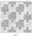
- FIG. 4 illustrates an example of a duty ratio DR.
- each square may represent a dot corresponding to a light-emitting diode in the exposure unit 29.
- a dot may be the smallest unit in an image forming operation.
- a dot with oblique lines may represent a dot in which the light-emitting diode emits light
- a white dot may represent a dot in which the light-emitting diode does not emit light.
- the shade of the toner density may be expressed through so-called area coverage modulation.
- area coverage modulation For example, in a pixel P, the toner density in that pixel P may be higher as the number of dots in which the light-emitting diodes emit light is greater. In a pixel P, the toner density in that pixel P may be lower as the number of dots in which the light-emitting diodes emit light is smaller.
- the duty ratio DR may represent the proportion of the dots in which the light-emitting diodes emit light with respect to all of the dots within a given pixel P.
- the duty ratio DR in that pixel P may be 100%.
- the duty ratio DR may be 0%. In the example illustrated in FIG. 4 , the duty ratio DR is about 50%. In this manner, the toner density in each pixel P may correlate with the duty ratio DR.
- the duty ratio calculator 52A may obtain the duty ratios DR, i.e., the duty ratios DRY, DRM, DRC, and DRW, in each pixel P on the basis of the four pieces of image data D2Y, D2M, D2C, and D2W, respectively. Thereafter, the duty ratio calculator 52A may obtain the total value, i.e., the total duty ratio DRtotal, of the four duty ratios DRY, DRM, DRC, and DRW in each pixel P. Further, the duty ratio calculator 52A may correct the duty ratio DRW in each pixel P and thereby cause the total duty ratio DRtotal to become no lower than the target duty ratio DRA.
- the duty ratio calculator 52A may correct the duty ratio DRW in each pixel P and thereby cause the total duty ratio DRtotal to become no lower than the target duty ratio DRA.
- the duty ratio calculator 52A may thereafter update the white image data D2W on the basis of the corrected duty ratio DRW.
- This configuration makes it possible to ensure no smaller than a predetermine amount of toner in each pixel P in the image forming apparatus 1, as will be described later.
- it is possible to obtain favorable transfer characteristics when an image is transferred from the transfer print medium 9 onto a T-shirt, which makes it possible to improve the image quality as a result.
- the operation section 53 may receive a user operation.
- the operation section 53 may include components such as various buttons, for example.
- the display section 54 may display information such as an operating state of the image forming apparatus 1 and an instruction to the user.
- the display section 54 may include a liquid crystal display or various indicators, for example.
- the ROM 55 may hold a program to be executed in the image forming apparatus 1.
- the RAM 56 may serve as a transitory storage area used when the image forming apparatus 1 executes a program.
- the non-volatile memory 57 may hold various pieces of setting information in the image forming apparatus 1.
- the non-volatile memory 57 may hold duty ratio information INF.
- the duty ratio information INF may hold the target duty ratio DRA.
- the target duty ratio DRA may be such a total duty ratio DRtotal that makes it possible to obtain favorable transfer characteristics when an image is transferred from the transfer print medium 9 onto a T-shirt.
- the target duty ratio DRA may be set in advance in the image forming apparatus 1.
- the non-volatile memory 57 may also be able to hold, as the duty ratio information INF, the target duty ratio DRA generated on the basis of a user operation, in accordance with an instruction from the target duty ratio generator 58.
- the target duty ratio generator 58 may generate the target duty ratio DRA on the basis of information input by the user operating the operation section 53, for example.
- the generated target duty ratio DRA may be stored as the duty ratio information INF into the non-volatile memory 57.
- the controller 59 may control an overall operation of the image forming apparatus 1 by controlling an operation of each block in the image forming apparatus 1.
- the controller 59 may have a timer embedded therein, for example, and determine operation timing of each block with the use of the timer.
- the high-voltage power source section 61 may generate various voltages, e.g., the charging voltage VCH, the developing voltage VDB, the feeding voltage VSB, and the transfer voltage VTR, used in the developing units 20 and the transfer section 30.
- various voltages e.g., the charging voltage VCH, the developing voltage VDB, the feeding voltage VSB, and the transfer voltage VTR, used in the developing units 20 and the transfer section 30.
- the sensor I/O port 62 may receive detection results in various sensors, such as print medium sensors 13, 14, 16, 18, and 43.
- the I/O port 63 may supply the motor driving sections 71A to 75A with control signals for causing the respective motors to operate.
- the I/O port 63 may also supply the heater driving section 76A with a control signal for causing the heater 76B to operate.
- the motor driving section 71A may drive the print medium feeding roller motor 71B.
- the print medium feeding roller motor 71B may supply motive power to the pickup roller 11 and the print medium feeding roller 12.
- the motor driving section 72A may drive the registration roller motor 72B.
- the registration roller motor 72B may supply motive power to the registration rollers 15 and 17.
- the motor driving section 73A may drive the photosensitive drum motor 73B.
- the photosensitive drum motor 73B may supply motive power to the photosensitive drums 21, the developing rollers 25, and the feeding rollers 27 in the respective four developing units 20.
- the motor driving section 74A may drive the transfer belt motor 74B.
- the transfer belt motor 74B may supply motive power to the driving roller 33.
- the motor driving section 75A may drive the fixing roller motor 75B.
- the fixing roller motor 75B may supply motive power to the fixing roller 41.
- the print medium feeding roller motor 71B, the registration roller motor 72B, the photosensitive drum motor 73B, the transfer belt motor 74B, and the fixing roller motor 75B may each include a stepping motor, i.e., a pulse motor, for example.
- the heater driving section 76A may drive the heater 76B provided in the fixing roller 41.
- the exposure controller 64 may control an exposure operation in the four exposure units 29 on the basis of the image data D2, i.e., the image data D2Y, D2M, D2C, and D2W.
- the exposure controller 64 may control an exposure operation in the exposure unit 29Y on the basis of the image data D2Y, control an exposure operation in the exposure unit 29M on the basis of the image data D2M, control an exposure operation in the exposure unit 29C on the basis of the image data D2C, and control an exposure operation in the exposure unit 29W on the basis of the image data D2W.
- the DRAM 65 may temporarily hold the image data D2.
- the image processing section 52, the target duty ratio generator 58, and the controller 59 may include, for example, a processor that is able to execute a program.
- the image processing section 52 may correspond to an "image processing section” in one specific but non-limiting embodiment of the technology.
- the image data D2Y, D2M, D2C, and D2W may correspond to a "plurality of pieces of image data" in one specific but non-limiting embodiment of the technology.
- the yellow toner, the magenta toner, and the cyan toner may correspond to "one or more basic color developers" in one specific but non-limiting embodiment of the technology.
- the white toner may correspond to an "auxiliary color developer” in one specific but non-limiting embodiment of the technology.
- the developing units 20Y, 20M, 20C, and 20W may correspond to an "image forming section" in one specific but non-limiting embodiment of the technology.
- the duty ratio DR may correspond to a "pixel value" in one specific but non-limiting embodiment of the technology.
- the total duty ratio DRtotal may correspond to a "developer amount” in one specific but non-limiting embodiment of the technology.
- the target duty ratio DRA may correspond to a "predetermined amount” in one specific but non-limiting embodiment of the technology.
- the target duty ratio generator 58 may correspond to a "setting section" in one specific but non-limiting embodiment of the technology.
- the image processing section 52 may convert the image data D1 included in the print data DP into the image data D2, i.e., the image data D2Y, D2M, D2C, and D2W.
- the image data D2 may be bitmap data of a so-called pixel format.
- the heater 76B and the fixing roller motor 75B may start operating, and a warm-up operation may thus be performed. This operation may bring the temperature of the fixing section 40 to a temperature appropriate for a fixing operation.
- the print medium feeding roller motor 71B, the registration roller motor 72B, and the fixing roller motor 75B may start operating.
- the pickup roller 11 may pick up the transfer print medium 9 stored in the print medium container 8, and the print medium feeding roller 12 may convey the transfer print medium 9 along the conveyance path 10.
- the registration roller 15 may correct a skew of the transfer print medium 9 by performing a so-called abutting process.
- an operating state of an unillustrated clutch provided in a motive power transmission path from the registration roller motor 72B to the registration roller 15 may enter a state in which no motive power is transmitted, for example, for a predetermine duration, for example, on the basis of the detection result of the print medium sensor 13.
- the registration roller 15 may stop rotating, and the skew of the transfer print medium 9 may be corrected. Thereafter, upon the clutch entering a state of transmitting motive power, the registration roller 15 may start rotating again, and the transfer print medium 9 may be conveyed.
- the photosensitive drum motor 73B and the transfer belt motor 74B may start operating at timing that is sufficiently prior to timing at which the transfer print medium 9 reaches the transfer belt 31. Thereby, the photosensitive drum 21 in each developing unit 20 may rotate, and the transfer belt 31 may circulate at a conveyance speed that is substantially equal to the circumferential speed of the photosensitive drum 21. Thus, the transfer belt 31 may convey the transfer print medium 9 along the four developing units 20.
- the high-voltage power source section 61 may generate the charging voltage VCH, the developing voltage VDB, the feeding voltage VSB, and the transfer voltage VTR.
- the exposure controller 64 may control the exposure operation in the four exposure units 29 on the basis of the image data D2, i.e., the image data D2Y, D2M, D2C, and D2W. Thereby, first, an electrostatic latent image may be formed on the surface of the photosensitive drum 21 in each developing unit 20. Thereafter, a toner image may be formed, or developed, in accordance with the electrostatic latent image. The toner image on the photosensitive drum 21 in each developing unit 20 may thereafter be transferred onto the transfer target surface of the transfer print medium 9.
- a yellow toner image, a magenta toner image, a cyan toner image, and a white toner image may be formed in this order on the transfer print medium 9.
- the white toner image may be formed in the uppermost layer of the transfer print medium 9.
- the photosensitive drum motor 73B and the transfer belt motor 74B may stop operating.
- the timing at which the trailing end of the transfer print medium 9 passes through the developing unit 20W may be estimated on the basis of, for example, the size of the transfer print medium 9 and the number of driving pulses of the transfer belt motor 74B counted after the leading end of the transfer print medium 9 has passed through the print medium sensor 18.
- the timing at which the trailing end of the transfer print medium 9 passes through the developing unit 20W may be estimated on the basis of the size of the transfer print medium 9 and the number of driving pulses of the transfer belt motor 74B counted after the leading end of the transfer print medium 9 has passed through the print medium sensor 43.
- the photosensitive drum motor 73B and the transfer belt motor 74B may continue operating, and the photosensitive drum motor 73B and the transfer belt motor 74B may stop operating after the trailing end of the last transfer print medium 9 has passed through the developing unit 20W.
- the toner on the transfer print medium 9 may be fixed onto the transfer print medium 9 with the heat from the fixing roller 41 heated by the heater 76B and the pressure applied by the backup roller 42. Thereafter, the conveyance path switching section 45 may send out the transfer print medium 9 having the toner fixed thereto to a path selected from the conveyance path 10A, which is the path leading to the face-up stacker 46, and the conveyance path 10B, which is the path leading to the face-down stacker 49. Thereby, the transfer print medium 9 may be discharged to the face-up stacker 46 or the face-down stacker 49.
- the image processing section 52 may convert the image data D1 included in the print data DP into the image data D2.
- the image data D2 may be bitmap data of a so-called pixel format.
- the duty ratio calculator 52A may obtain the duty ratios DR, i.e., the duty ratios DRY, DRM, DRC, and DRW, in each pixel P on the basis of the four pieces of image data D2Y, D2M, D2C, and D2W. Thereafter, the duty ratio calculator 52A may obtain the total value, i.e., the total duty ratio DRtotal, of the four duty ratios DRY, DRM, DRC, and DRW in each pixel P.
- the duty ratio calculator 52A may correct the duty ratio DRW in each pixel P and thereby cause the total duty ratio DRtotal to become no lower than the target duty ratio DRA in the relevant pixel P.
- the image processing section 52 may update the white image data D2W on the basis of the corrected duty ratio DRW. This operation will be described below in detail.
- FIG. 5 schematically illustrates an operation of the duty ratio calculator 52A.
- a duty ratio DRW0 represents an uncorrected duty ratio DRW
- a duty ratio DRW1 represents a corrected duty ratio DRW.
- the expression ⁇ DRW represents a correction value of the duty ratio DRW.
- each portion indicated by a thick line represents the total duty ratio DRtotal obtained with the use of the uncorrected duty ratio DRW.
- FIG. 5 illustrates an example of so-called single-color image formation in which one of yellow, magenta, and cyan is used.
- yellow is used.
- this is not a limiting example, and an example may be so-called mixed-color image formation in which two or more colors of yellow, magenta, and cyan are used.
- the duty ratio DRY of yellow is from 20% to 100%
- the duty ratio DRW, i.e., DRWO, of white is 20%
- the duty ratio DRM of magenta and the duty ratio DRC of cyan are both 0%.
- the white toner may be used, for example, to reduce an influence of the ground color of a T-shirt onto an image.
- the duty ratio DRW i.e., DRWO
- the duty ratio DRW i.e., DRWO
- the target duty ratio DRA is set to 100% in this example.
- the target duty ratio DRA may be set in advance in the image forming apparatus 1.
- the duty ratio calculator 52A may correct the duty ratio DRW, i.e., DRW1, of white to 80% by setting the correction value ⁇ DRW to 60%. In other words, in this case, since the total duty ratio DRtotal, which is 40%, is lower than the target duty ratio DRA, which is 100%, the duty ratio calculator 52A may bring the corrected total duty ratio DRtotal to 100% by correcting the duty ratio DRW, i.e., DRW1, of white to 80%.
- the duty ratio calculator 52A may correct the duty ratio DRW, i.e., DRW1, of white to 60% by setting the correction value ⁇ DRW to 40%.
- the duty ratio calculator 52A may correct the duty ratio DRW, i.e., DRW1, of white to 40% by setting the correction value ⁇ DRW to 20%.
- the duty ratio calculator 52A may make no correction to the duty ratio DRW. In other words, in this case, since the total duty ratio DRtotal, which is 100%, is at the target duty ratio DRA, which is 100%, the duty ratio calculator 52A may make no correction to the duty ratio DRW.
- the duty ratio calculator 52A may make no correction to the duty ratio DRW.
- the pixel value corresponding to the white toner may be so corrected as to cause the toner amount obtained when the four color toners, i.e., the yellow, magenta, cyan, and white toners, are disposed on each other to fall within a predetermined range.
- the duty ratio DRW of white may be so corrected as to cause the total duty ratio DRtotal to become no lower than the target duty ratio DRA.
- a user may place an adhesive on an image portion of the transfer print medium 9 with the use of an adhesive sheet.
- a sufficient amount of adhesive may not be able to be placed on the image portion of the transfer print medium 9.
- the image on the transfer print medium 9 may not be adhered sufficiently to the T-shirt when the user transfers the image from the transfer print medium 9 onto the T-shirt thereafter with the use of an iron, and the image quality of the image transferred onto the T-shirt may be lowered as a result.
- the duty ratio DRW of white may be so corrected as to cause the total duty ratio DRtotal to become no lower than the target duty ratio DRA.
- the image forming apparatus 1 makes it possible to ensure a sufficient amount of adhesive to be placed on the image portion of the transfer print medium 9 and thus makes it possible to obtain favorable transfer characteristics when the image is transferred from the transfer print medium 9 onto a T-shirt.
- the image forming apparatus 1 makes it possible to improve the image quality of the image transferred onto a T-shirt.
- a user sets the target duty ratio DRA.
- the user may input information on the fabric of a T-shirt by operating the operation section 53, and the target duty ratio generator 58 may generate the target duty ratio DRA on the basis of the information input by the user.
- the information on the fabric of the T-shirt may be the degree of smoothness of the fabric or may be the type of the fabric.
- the target duty ratio generator 58 may decrease the target duty ratio DRA. In a case where the degree of smoothness of the fabric is low, the target duty ratio generator 58 may increase the target duty ratio DRA.
- FIG. 6 schematically illustrates an operation of the duty ratio calculator 52A to be performed in a case where the target duty ratio DRA is set to a high value.
- the target duty ratio DRA is set to 140%.
- the duty ratio calculator 52A may correct the duty ratio DRW of white and thereby cause the total duty ratio DRtotal to become no lower than the target duty ratio DRA.
- the image forming apparatus 1 makes it possible to further increase the amount of adhesive to be placed on the image portion of the transfer print medium 9 and thus makes it possible to improve the image quality of the image transferred onto the T-shirt.
- the user may input information on a preference of the user by operating the operation section 53, and the target duty ratio generator 58 may generate the target duty ratio DRA on the basis of the information input by the user.
- the information on the preference of the user may be a retro style of an image.
- the target duty ratio generator 58 may be able to decrease the target duty ratio DRA. In this case, reducing the amount of adhesive to be placed makes it possible to increase an influence of the ground color of the T-shirt onto the image. Thus, it is possible to obtain a yellowish image in a case where the ground color of the T-shirt is yellow, which makes it possible to form an image in the retro style.
- the user may be allowed to directly input the target duty ratio DRA itself by operating the operation section 53, for example. This may allow the user having full knowledge of the performance of the image forming apparatus 1 to set the setting of the image forming apparatus 1 more directly and in a more detailed manner, for example.
- the correction value ⁇ DRW of the duty ratio DRW of white may be adjusted in accordance with the total duty ratio DRtotal in the image forming apparatus 1, which makes it possible to reduce a consumption amount of the white toner.
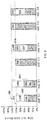
- the correction value ⁇ DRW is set to a predetermined amount regardless of the total duty ratio DRtotal as in the example illustrated in FIG. 7 , the consumption amount of the white toner increases in the cases C2 to C5, in particular.
- the amount of adhesive to be placed is small in the case C1, and thus the image quality may decrease.
- the correction value ⁇ DRW of the duty ratio DRW of white may be adjusted in accordance with the total duty ratio DRtotal in the image forming apparatus 1.
- the correction value ⁇ DRW may be so adjusted as to cause the total duty ratio DRtotal to become substantially equal to the target duty ratio DRA.
- no correction may be made to the duty ratio DRW of white. This makes it possible to keep the duty ratio DRW of white at a certain level in the image forming apparatus 1, as illustrated in FIG. 5 , which makes it possible to reduce the consumption amount of the white toner.
- FIG. 8 illustrates an example of an operation of generating the image data D2 on the basis of the print data DP in the image forming apparatus 1.
- the communication section 51 may receive the print data DP transmitted from a host computer (step S101).
- the image processing section 52 may convert the image data D1 included in the print data DP into the image data D2, i.e., the image data D2Y, D2M, D2C, and D2W (step S102).
- the image data D2 may be bitmap data of a so-called pixel format.
- the duty ratio calculator 52A of the image processing section 52 may generate duty ratio data D3 by obtaining the duty ratio DR in each pixel P on the basis of the image data D2 (step S103).
- the duty ratio calculator 52A may generate duty ratio data D3Y by obtaining the duty ratio DRY in each pixel P on the basis of the yellow image data D2Y.
- the duty ratio data D3Y may be map data of the duty ratio DRY.
- the duty ratio calculator 52A may generate duty ratio data D3M by obtaining the duty ratio DRM in each pixel P on the basis of the magenta image data D2M.
- the duty ratio data D3M may be map data of the duty ratio DRM.
- the duty ratio calculator 52A may generate duty ratio data D3C by obtaining the duty ratio DRC in each pixel P on the basis of the cyan image data D2C.
- the duty ratio data D3C may be map data of the duty ratio DRC.
- the duty ratio calculator 52A may generate duty ratio data D3W by obtaining the duty ratio DRW in each pixel P on the basis of the white image data D2W.
- the duty ratio data D3W may be map data of the duty ratio DRW.
- the duty ratio calculator 52A may select one of the pixels P (step S104).
- the duty ratio calculator 52A may obtain the total duty ratio DRtotal in the selected pixel P on the basis of the duty ratio data D3 (step S105).
- the duty ratio calculator 52A may obtain the total duty ratio DRtotal in the selected pixel P by obtaining a total value of the duty ratio DRY in the selected pixel P in the duty ratio data D3Y, the duty ratio DRM in the selected pixel P in the duty ratio data D3M, the duty ratio DRC in the selected pixel P in the duty ratio data D3C, and the duty ratio DRW in the selected pixel P in the duty ratio data D3W.
- the duty ratio calculator 52A may determine whether the total duty ratio DRtotal is lower than the target duty ratio DRA, i.e., whether DRtotal ⁇ DRA holds (step S106). In a case where the total duty ratio DRtotal is no lower than the target duty ratio DRA ("N" in step S106), the duty ratio calculator 52A may proceed to step S109. In other words, in this case, since the total duty ratio DRtotal is at or higher than the target duty ratio DRA as in the cases C4 and C5 illustrated in FIG. 5 , it is possible to ensure a certain amount of adhesive to be placed. Therefore, the duty ratio calculator 52A may make no correction to the duty ratio DRW.
- the duty ratio calculator 52A may correct the duty ratio DRW to bring the total duty ratio DRtotal to the target duty ratio DRA and may update the white image data D2W on the basis of the corrected duty ratio DRW (step S108). Thereafter, the duty ratio calculator 52A may proceed to step S109.
- the duty ratio calculator 52A may determine whether all of the pixels P in the image data D2 have been selected (step S109). In a case where not all of the pixels P have been selected ("N" in step S109), the duty ratio calculator 52A may select a pixel P that has not yet been selected (step S110) and return to step S105. Thereafter, the operation in steps S105 to S110 may be repeated until all of the pixels P are selected.
- step S109 In a case where it is determined in step S109 that all of the pixels P have been selected ("Y" in step S109), the flow is brought to an end.
- the duty ratio of white may be so corrected as to cause the total duty ratio to become no lower than the target duty ratio.
- the correction value of the duty ratio of white may be adjusted in accordance with the total duty ratio.
- the total duty ratio may be adjusted in accordance with the total duty ratio.
- the duty ratio DRW of white may be corrected on the basis of a plurality of target duty ratios. It is to be noted that components that are substantially identical to those of the image forming apparatus 1 according to the first example embodiment described above will be given identical reference characters, and descriptions thereof will be omitted as appropriate.
- the image forming apparatus 2 may include an image processing section 82, a non-volatile memory 87, a target duty ratio generator 88, and a controller 89.
- the image processing section 82 may include a duty ratio calculator 82A.
- the duty ratio calculator 82A may obtain the duty ratios DR, i.e., the duty ratios DRY, DRM, DRC, and DRW, in each pixel P on the basis of the four pieces of image data D2Y, D2M, D2C, and D2W, respectively.
- the duty ratio calculator 82A may obtain the total value, i.e., the total duty ratio DRtotal, of the four duty ratios DRY, DRM, DRC, and DRW in each pixel P.
- the duty ratio calculator 82A may correct the duty ratio DRW in a given single-color pixel P and thereby cause the total duty ratio DRtotal to become no lower than the target duty ratio DRA in that pixel P.
- the duty ratio calculator 82A may also correct the duty ratio DRW in a given mixed-color pixel P and thereby cause the total duty ratio DRtotal to become no lower than a target duty ratio DRB in that pixel P. Thereafter, the duty ratio calculator 82A may update the white image data D2W on the basis of the corrected duty ratio DRW.
- the non-volatile memory 87 may hold duty ratio information INF2.
- the duty ratio information INF2 may hold the target duty ratios DRA and DRB.
- the target duty ratio DRA may be such a total duty ratio DRtotal that makes it possible to obtain favorable transfer characteristics when a single-color image including only one color of yellow, magenta, and cyan is transferred from the transfer print medium 9 onto a T-shirt.
- the target duty ratio DRB may be such a total duty ratio DRtotal that makes it possible to obtain favorable transfer characteristics when a mixed-color image including two or more colors of yellow, magenta, and cyan is transferred from the transfer print medium 9 onto a T-shirt.
- the target duty ratio DRB may be higher than the target duty ratio DRA.
- the target duty ratios DRA and DRB may be set in advance in the image forming apparatus 2.
- the non-volatile memory 87 may be able to hold, as the duty ratio information INF2, the target duty ratios DRA and DRB generated on the basis of a user operation in accordance with an instruction from the target duty ratio generator 88.
- the target duty ratio generator 88 may generate the target duty ratios DRA and DRB on the basis of information input by the user operating the operation section 53, for example.
- the generated target duty ratios DRA and DRB may be stored as the duty ratio information INF2 into the non-volatile memory 87.
- the controller 89 may control an overall operation of the image forming apparatus 2 by controlling an operation of each block in the image forming apparatus 2.
- FIG. 9 schematically illustrates an operation of the duty ratio calculator 82A.
- an operation of correcting the duty ratio DRW in a pixel P of interest is illustrated.
- each portion indicated by a thick line may represent the total duty ratio DRtotal obtained with the use of the uncorrected duty ratio DRW.
- the cases C11, C13, and C15 are for illustrating an operation example with a single color
- the cases C12, C14, and C16 are for illustrating an operation example with a mixed color.
- the duty ratio DRY of yellow is from 40% to 100%
- the duty ratio DRW, i.e., DRWO, of white is 20%
- the duty ratio DRM of magenta and the duty ratio DRC of cyan are both 0%.
- the duty ratio DRY of yellow and the duty ratio DRM of magenta are each from 20% to 50%
- the duty ratio DRW, i.e., DRWO, of white is 20%
- the duty ratio DRC of cyan is 0%.
- the total duty ratios DRtotal in an uncorrected state may be equal to each other.
- the total duty ratios DRtotal in an uncorrected state may be equal to each other.
- the target duty ratio DRA is set to 100%
- the target duty ratio DRB is set to 120%.
- the duty ratio calculator 82A may correct the duty ratio DRW, i.e., DRW1, of white to 60% by setting the correction value ⁇ DRW to 40%. In other words, in this case, since only the duty ratio DR of one color of yellow, magenta, and cyan, i.e., only the duty ratio DR of yellow, is positive, the duty ratio calculator 82A may determine that this is a case of a single color and select the target duty ratio DRA from the target duty ratios DRA and DRB.
- the duty ratio calculator 82A may bring the corrected total duty ratio DRtotal to 100% by correcting the duty ratio DRW, i.e., DRW1, of white to 60%.
- the duty ratio calculator 82A may correct the duty ratio DRW, i.e., DRW1, of white to 80% by setting the correction value ⁇ DRW to 60%.
- the duty ratio calculator 82A may determine that this is a case of a mixed color and select the target duty ratio DRB from the target duty ratios DRA and DRB. Further, since the total duty ratio DRtotal, which is 60%, is lower than the target duty ratio DRB, which is 120%, the duty ratio calculator 82A may bring the corrected total duty ratio DRtotal to 120% by correcting the duty ratio DRW, i.e., DRW1, of white to 80%.
- the duty ratio calculator 82A may make no correction to the duty ratio DRW.
- the duty ratio calculator 82A may determine that this is a case of a single color and select the target duty ratio DRA from the target duty ratios DRA and DRB. Further, since the total duty ratio DRtotal, which is 100%, is at the target duty ratio DRA, which is 100%, the duty ratio calculator 82A may make no correction to the duty ratio DRW.
- the duty ratio calculator 82A may correct the duty ratio DRW, i.e., DRW1, of white to 40% by setting the correction value ⁇ DRW to 20%.
- the duty ratio calculator 82A may determine that this is a case of a mixed color and select the target duty ratio DRB from the target duty ratios DRA and DRB. Further, since the total duty ratio DRtotal, which is 100%, is lower than the target duty ratio DRB, which is 120%, the duty ratio calculator 82A may bring the corrected total duty ratio DRtotal to 120% by correcting the duty ratio DRW of white to 40%.
- the duty ratio calculator 82A may make no correction to the duty ratio DRW.
- the duty ratio calculator 82A may determine that this is a case of a single color and select the target duty ratio DRA from the target duty ratios DRA and DRB. Further, since the total duty ratio DRtotal, which is 120%, is higher than the target duty ratio DRA, which is 100%, the duty ratio calculator 82A may make no correction to the duty ratio DRW.
- the duty ratio calculator 82A may make no correction to the duty ratio DRW.
- the duty ratio calculator 82A may determine that this is a case of a mixed color and select the target duty ratio DRB from the target duty ratios DRA and DRB. Further, since the total duty ratio DRtotal, which is 120%, is at the target duty ratio DRB, which is 120%, the duty ratio calculator 82A may make no correction to the duty ratio DRW.
- the target duty ratio may be set in accordance with the number of colors composing an image, and the duty ratio DRW of white may be corrected with the use of the set target duty ratio.
- the amount of adhesive to be placed on the image portion of the transfer print medium 9 may be reduced as the number of colors is greater.
- one of a plurality of target duty ratios e.g., of two target duty ratios DRA and DRB in this example, may be selected in accordance with the number of colors composing the image.
- the target duty ratio DRA may be selected in the case of a single color
- the target duty ratio DRB which is higher than the target duty ratio DRA, may be selected in the case of a mixed color.
- the image forming apparatus 2 makes it possible to increase the amount of adhesive to be placed on the image portion of the transfer print medium 9 in the case of a mixed color as compared to that in the case of a single color and to thus makes it possible to improve the image quality of the image transferred onto the T-shirt.
- the number of colors composing an image may be determined in each pixel P, and the target duty ratio may be set in accordance with the determination result.
- the image forming apparatus 2 may select the target duty ratio DRA in a pixel P with a single color and select the target duty ratio DRB, which is higher than the target duty ratio DRA, in a pixel P with a mixed color. This makes it possible to decrease the duty ratio DR of white in a pixel P with a single color as compared to that in a pixel P with a mixed color. Thus, it is possible to reduce the consumption amount of the white toner more effectively.
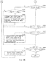
- FIGs. 10A and 10B illustrate an example of an operation of generating the image data D2 on the basis of the print data DP in the image forming apparatus 2.
- the communication section 51 may receive the print data DP transmitted from a host computer (step S101), and the image processing section 82 may convert the image data D1 included in the print data DP into the image data D2, i.e., the image data D2Y, D2M, D2C, and D2W (step S102).
- the image data D2 may be bitmap data of a so-called pixel format.
- the duty ratio calculator 82A of the image processing section 82 may generate the duty ratio data D3 by obtaining the duty ratio DR in each pixel P on the basis of the image data D2 (step S103).
- the duty ratio calculator 82A may select one of the pixels P (step S104).
- the duty ratio calculator 82A may obtain the total duty ratio DRtotal in the selected pixel P on the basis of the duty ratio data D3 (step S105).
- the duty ratio calculator 82A may determine whether it is a case of a single color (step S201).
- the duty ratio calculator 82A may determine whether the total duty ratio DRtotal is lower than the target duty ratio DRB, i.e., whether DRtotal ⁇ DRB holds (step S202).
- step S202 In a case where it is determined in step S202 that the total duty ratio DRtotal is no lower than the target duty ratio DRB ("N" in step S202), the duty ratio calculator 82A may proceed to step S109.
- the total duty ratio DRtotal is at or higher than the target duty ratio DRB, for example, as in the case C16 illustrated in FIG. 9 , it is possible to ensure a certain amount of adhesive to be placed, and thus the duty ratio calculator 82A may make no correction to the duty ratio DRW.
- the duty ratio calculator 82A may correct the duty ratio DRW to bring the total duty ratio DRtotal to the target duty ratio DRB and update the white image data D2W on the basis of the corrected duty ratio DRW (step S203). Thereafter, the duty ratio calculator 82A may proceed to step S109.
- the duty ratio calculator 82A may determine whether the total duty ratio DRtotal is lower than the target duty ratio DRA, i.e., whether DRtotal ⁇ DRA holds (step SI06). In a case where the total duty ratio DRtotal is no lower than the target duty ratio DRA ("N" in step S106), the duty ratio calculator 82A may proceed to step S109.
- the duty ratio calculator 82A may correct the duty ratio DRW to bring the total duty ratio DRtotal to the target duty ratio DRA and update the white image data D2W on the basis of the corrected duty ratio DRW (step S108). Thereafter, the duty ratio calculator 82A may proceed to step S109.
- the duty ratio calculator 82A may determine whether all of the pixels P in the image data D2 have been selected (step S109). In a case where not all of the pixels P have been selected ("N" in step S109), the duty ratio calculator 82A may select a pixel P that has not yet been selected (step S110) and return to step S105.
- step S109 In a case where it is determined in step S109 that all of the pixels P have been selected ("Y" in step S109), the flow is brought to an end.
- the target duty ratio may be set in accordance with the number of colors composing an image.
- a mixed color for example, it is possible to increase the amount of adhesive to be placed in an image portion of a transfer print medium and thus to improve the image quality.
- the number of colors composing an image may be determined in each pixel P, and the target duty ratio may be set in accordance with the determination result.
- the target duty ratio may be set in accordance with the determination result.
- an image may be transferred from the transfer print medium 9 onto a T-shirt in each of the example embodiments described above; however, this is not a limiting example.
- an image may be formed with the use of toners of four colors, i.e., yellow, magenta, cyan, and white, in each of the example embodiments described above; however, this is not a limiting example.
- an image may be formed with the use of toners of two colors or three colors, or an image may be formed with the use of toners of five colors, e.g., yellow, magenta, cyan, black, and white.
- the duty ratio DRW of white may be corrected in the example embodiments described above; however, this is not a limiting example.
- the duty ratio DR of the transparent toner may be corrected.
- a developing unit for forming an image with the use of the transparent toner may be disposed on the most downstream side or the most upstream side in the conveying direction F.
- the technology may be applied to a single-function printer in the example embodiments described above; however, this is not a limiting example.
- the technology may be applied, for example, to a copier or may be applied, for example, to as a so-called multifunction peripheral (MFP) having functions such as a copy function, a fax function, a scan function, and a print function.
- MFP multifunction peripheral
- toner images formed by the developing units 20 may be transferred directly onto the transfer print medium 9 in the example embodiments described above; however, this is not a limiting example.
- toner images formed by the developing units 20 may be transferred once onto an intermediate transfer belt, and the toner images that have been transferred onto the intermediate transfer belt may be transferred onto the transfer print medium 9.
- the technology encompasses any possible combination of some or all of the various embodiments and the modifications described herein and incorporated herein. It is possible to achieve at least the following configurations from the above-described example embodiments of the technology.
- the pixel value corresponding to the auxiliary color developer is so corrected as to cause the developer amount, which is the total amount of the one or more basic color developers and the auxiliary color developer when the one or more basic color developers and the auxiliary color developer are disposed on each other, to fall within the predetermined range.
- the developer amount which is the total amount of the one or more basic color developers and the auxiliary color developer when the one or more basic color developers and the auxiliary color developer are disposed on each other
- Each of the image processing sections 52 and 82 illustrated in FIG. 3 is implementable by circuitry that includes at least one of a field programmable gate array (FPGA), a semiconductor integrated circuit, and an application specific integrated circuit (ASIC).
- the FPGA is an integrated circuit (IC) designed to be configured after manufacturing in order to perform all or a part of the functions of each of the image processing sections 52 and 82 illustrated in FIG. 3 .
- the ASIC is an IC customized to perform all or a part of the functions of each of the image processing sections 52 and 82 illustrated in FIG. 3 .
- the semiconductor integrated circuit may be, for example, at least one processor such as a central processing unit (CPU).
- the processor may be configurable to read instructions from at least one machine readable tangible non-transitory medium to thereby perform all or a part of functions of each of the image processing sections 52 and 82 illustrated in FIG. 3 .
- the form of such a medium may include, for example, any type of magnetic medium, any type of optical medium, or any type of semiconductor memory (i.e., semiconductor circuit).
- the magnetic medium may be a hard disk, for example.
- the optical medium may be a CD or a DVD, for example.
- the semiconductor memory may be a volatile memory or a non-volatile memory, for example.
- the volatile memory may include a DRAM or a SRAM, for example.
- the nonvolatile memory may include a ROM or a NVRAM, for example.
Landscapes
- Physics & Mathematics (AREA)
- General Physics & Mathematics (AREA)
- Engineering & Computer Science (AREA)
- Multimedia (AREA)
- Signal Processing (AREA)
- Microelectronics & Electronic Packaging (AREA)
- Computer Vision & Pattern Recognition (AREA)
- Theoretical Computer Science (AREA)
- Color Electrophotography (AREA)
- Control Or Security For Electrophotography (AREA)
Abstract
Description
- The technology relates to an image forming apparatus that forms an image on a transfer print medium.
- There exists an image forming apparatus that uses, for example, a white toner in addition to color toners, i.e., basic color toners, for forming an image. The basic colors toners include, for example, a cyan toner, a magenta toner, a yellow toner, and a black toner. The white toner is used, for example, to reduce an influence of a ground color of a recording print medium on an image, as disclosed in Japanese Unexamined Patent Application Publication No.
2014-216721 - For example, in a case where an image is to be formed on a T-shirt, a transfer sheet, i.e., a transfer print medium, may often be used. In one example, an image may be formed once on a transfer print medium, an adhesive may be placed onto an image portion of this transfer print medium with the use of an adhesive sheet, and the image may be transferred onto the T-shirt from the transfer print medium with the use of an iron, for example. Even in this case, it is expected that a high image quality be achieved.
- It is desirable to provide an image forming apparatus that makes it possible to improve an image quality.
- According to one embodiment of the technology, there is provided an image forming apparatus that includes an image processing section and an image forming section. The image processing section corrects, on the basis of a plurality of pieces of image data, a pixel value corresponding to an auxiliary color developer in a first pixel and thereby causes a developer amount in the first pixel to fall within a predetermined range. The plurality of pieces of image data corresponding to respective developers include one or more basic color developers that configure an image and the auxiliary color developer. The developer amount in the first pixel is a total amount of the one or more basic color developers and the auxiliary color developer in the first pixel when the one or more basic color developers and the auxiliary color developer are disposed on each other. The image forming section forms an image on a transfer print medium on the basis of the pieces of image data processed by the image processing section.
-
-
FIG. 1 is a descriptive diagram illustrating an example of a configuration of an image forming apparatus according to one embodiment. -
FIG. 2 is a descriptive diagram illustrating an example of a configuration of a developing unit illustrated inFIG. 1 . -
FIG. 3 is a block diagram illustrating an example of a configuration of the image forming apparatus illustratedFIG. 1 . -
FIG. 4 is a descriptive diagram illustrating an example of a duty ratio. -
FIG. 5 is a descriptive diagram illustrating an example of an operation of an image forming apparatus according to one embodiment. -
FIG. 6 is a descriptive diagram illustrating another example of an operation of an image forming apparatus according to one embodiment. -
FIG. 7 is a descriptive diagram illustrating an example of an operation of an image forming apparatus according to a reference example. -
FIG. 8 is a flowchart illustrating an example of an operation of an image forming apparatus according to one embodiment. -
FIG. 9 is a descriptive diagram illustrating an example of an operation of an image forming apparatus according to one embodiment. -
FIG. 10A is a flowchart illustrating an example of an operation of an image forming apparatus according to one embodiment. -
FIG. 10B is another flowchart illustrating an example of an operation of an image forming apparatus according to one embodiment. - Hereinafter, some example embodiments of the technology will be described in detail with reference to the drawings. Note that the following description is directed to illustrative examples of the technology and not to be construed as limiting to the technology. Factors including, without limitation, numerical values, shapes, materials, components, positions of the components, and how the components are coupled to each other are illustrative only and not to be construed as limiting to the technology. Further, elements in the following example embodiments which are not recited in a most-generic independent claim of the technology are optional and may be provided on an as-needed basis. The drawings are schematic and are not intended to be drawn to scale. Note that the like elements are denoted with the same reference numerals, and any redundant description thereof will not be described in detail. The description will be given in the following order.
- 1. First Example Embodiment
- 2. Second Example Embodiment
-
FIG. 1 illustrates an example of a configuration of an image forming apparatus, i.e., animage forming apparatus 1, according to an example embodiment of the technology. Theimage forming apparatus 1 may serve as a printer that forms an image on a transfer print medium with the use of an electrophotographic scheme. - The
image forming apparatus 1 may include apickup roller 11, a printmedium feeding roller 12,print medium sensors registration roller 15, aprint medium sensor 16, aregistration roller 17, aprint medium sensor 18, four developingunits 20, fourtoner containers 28, fourexposure units 29, atransfer section 30, afixing section 40, aprint medium sensor 43, aconveying roller 44, a conveyancepath switching section 45, aconveying roller 47, and adischarge roller 48. The four developingunits 20 may include developingunits toner containers 28 may includetoner containers exposure units 29 may includeexposure units conveyance path 10 through which atransfer print medium 9 is conveyed. - The
pickup roller 11 may pick up thetransfer print medium 9 stored in aprint medium container 8, one by one, from the uppermost sheet and send out the picked-uptransfer print medium 9 into theconveyance path 10. Thepickup roller 11 may rotate with motive power transmitted from a print mediumfeeding roller motor 71B, which will be described later. - The print
medium feeding roller 12 may convey, along theconveyance path 10, thetransfer print medium 9 fed from thepickup roller 11. The printmedium feeding roller 12 may rotate with motive power transmitted from the print mediumfeeding roller motor 71B, which will be described later. - The
print medium sensors transfer print medium 9. - The
registration roller 15 may include a pair of rollers disposed with theconveyance path 10 interposed therebetween. Theregistration roller 15 may correct a skew of the fedtransfer print medium 9 and convey thetransfer print medium 9 along theconveyance path 10. Theregistration roller 15 may rotate with motive power transmitted from aregistration roller motor 72B, which will be described later. - The
print medium sensor 16 may detect passage of thetransfer print medium 9. - The
registration roller 17 may include a pair of rollers disposed with theconveyance path 10 interposed therebetween. Theregistration roller 17 may correct a skew of the fedtransfer print medium 9 and convey thetransfer print medium 9 along theconveyance path 10. Theregistration roller 17 may rotate with motive power transmitted from theregistration roller motor 72B, which will be described later. - The
print medium sensor 18 may detect passage of thetransfer print medium 9. - The four developing
units 20 may form respective toner images. In one example, the developingunit 20Y may form a yellow (Y) toner image, the developingunit 20M may form a magenta (M) toner image, the developing unit 20C may form a cyan (C) toner image, and the developingunit 20W may form a white (W) toner image. In this example, the four developingunits 20 may be disposed in the order of the developingunits transfer print medium 9. Each of the developingunits 20 may be mountable and removable. - The four
toner containers 28 may each contain a toner. In one example, thetoner container 28Y may contain a yellow toner, thetoner container 28M may contain a magenta toner, the toner container 28C may contain a cyan toner, and thetoner container 28W may contain a white toner. The fourtoner containers 28 may each be mountable to and removable from the corresponding one of the four developingunits 20. -
FIG. 2 illustrates an example of a configuration of the developingunit 20.FIG. 2 depicts thetoner container 28 and theexposure unit 29 as well. The developingunit 20 may include aphotosensitive drum 21, acleaning blade 22, a chargingroller 24, a developingroller 25, a developingblade 26, and a feedingroller 27. - The
photosensitive drum 21 may support an electrostatic latent image on a surface thereof, i.e., on a surface layer portion thereof. In this example, thephotosensitive drum 21 may rotate counterclockwise with motive power transmitted from aphotosensitive drum motor 73B, which will be described later. Thephotosensitive drum 21 may be electrically charged by the chargingroller 24 and submitted to exposure by theexposure unit 29. In one example, thephotosensitive drum 21 in the developingunit 20Y may be submitted to exposure by theexposure unit 29Y, thephotosensitive drum 21 in the developingunit 20M may be submitted to exposure by theexposure unit 29M, thephotosensitive drum 21 in the developing unit 20C may be submitted to exposure by theexposure unit 29C, and thephotosensitive drum 21 in the developingunit 20W may be submitted to exposure by theexposure unit 29W. With this operation, an electrostatic latent image may be formed on the surface of eachphotosensitive drum 21. Thereafter, a toner may be fed to thephotosensitive drum 21 by the developingroller 25, and thus a toner image corresponding to the electrostatic latent image may be formed on thephotosensitive drum 21. - The
cleaning blade 22 may clean the surface, i.e., the surface layer portion, of thephotosensitive drum 21 by scraping any of remaining toner off the surface. Thecleaning blade 22 may be disposed with a tip thereof being in contact with thephotosensitive drum 21. - The charging
roller 24 may electrically charge the surface, i.e., the surface layer portion, of thephotosensitive drum 21 substantially uniformly. The chargingroller 24 may be so disposed as to be in contact with the surface, i.e., a peripheral surface, of thephotosensitive drum 21. The chargingroller 24 may be so disposed as to be pressed against thephotosensitive drum 21 at predetermined pressing force. In this example, the chargingroller 24 may rotate clockwise in response to the rotation of thephotosensitive drum 21. The chargingroller 24 may have a charging voltage VCH applied thereto by a high-voltagepower source section 61, which will be described later. - The developing
roller 25 may support a toner on a surface thereof. The developingroller 25 may be so disposed as to be in contact with the surface, i.e., the peripheral surface, of thephotosensitive drum 21. The developingroller 25 may be so disposed as to be pressed against thephotosensitive drum 21 at predetermined pressing force. In this example, the developingroller 25 may rotate clockwise with motive power transmitted from thephotosensitive drum motor 73B, which will be described later. The developingroller 25 may have a developing voltage VDB applied thereto by the high-voltagepower source section 61, which will be described later. - The developing
blade 26 may come into contact with the surface of the developingroller 25. Thus, the developingblade 26 may form a layer of a toner, i.e., a toner layer, on the surface of the developingroller 25 and control or adjust the thickness of the toner layer. The developingblade 26 may be, for example, a plate-shaped elastic member bent in an L-like shape and including a material such as stainless steel. The developingblade 26 may be disposed with its bent portion being in contact with the surface of the developingroller 25. The developingblade 26 may be so disposed as to be pressed against the developingroller 25 at predetermined pressing force. - The feeding
roller 27 may feed the toner contained in thetoner container 28 to the developingroller 25. The feedingroller 27 may be so disposed as to be in contact with the surface, i.e., the peripheral surface, of the developingroller 25. The feedingroller 27 may be so disposed as to be pressed against the developingroller 25 at predetermined pressing force. In this example, the feedingroller 27 may rotate clockwise with motive power transmitted from thephotosensitive drum motor 73B, which will be described later. With this configuration, friction may be produced between the surface of the feedingroller 27 and the surface of the developingroller 25 in each developingunit 20. As a result, the toner may become electrically charged through what is known as frictional charging in each developingunit 20. The feedingroller 27 may have a feeding voltage VSB applied thereto by the high-voltagepower source section 61, which will be described later. - The four
exposure units 29 illustrated inFIG. 1 may each irradiate, with light, thephotosensitive drum 21 in the corresponding one of the developingunits 20. In one example, theexposure unit 29Y may irradiate thephotosensitive drum 21 in the developingunit 20Y with light, theexposure unit 29M may irradiate thephotosensitive drum 21 in the developingunit 20M with light, theexposure unit 29C may irradiate thephotosensitive drum 21 in the developing unit 20C with light, and theexposure unit 29W may irradiate thephotosensitive drum 21 in the developingunit 20W with light. Theexposure units 29 may each include, for example, a plurality of light-emitting diodes that are arrayed in a main scanning line direction, which is the depthwise direction inFIG. 1 . Theexposure units 29 may each irradiate thephotosensitive drum 21 with light on a dot-by-dot basis with the use of the stated light-emitting diodes. With this configuration, each of thephotosensitive drums 21 may be submitted to exposure by corresponding one of theexposure units 29, and an electrostatic latent image may be formed on the surface of the relevantphotosensitive drum 21. - The
transfer section 30 may transfer the four toner images formed by the respective developingunits 20 onto a transfer target surface of thetransfer print medium 9. Thetransfer section 30 may include atransfer belt 31, four transfer rollers 32, a drivingroller 33, and a drivenroller 34. The four transfer rollers 32 may includetransfer rollers - The
transfer belt 31 may convey thetransfer print medium 9 in the conveying direction F along theconveyance path 10. Thetransfer belt 31 may lie on the drivingroller 33 and the drivenroller 34 while being stretched. Thus, thetransfer belt 31 may be conveyed in a circulating manner in the conveying direction F in response to the rotation of the drivingroller 33. - The four transfer rollers 32 may each transfer, onto the
transfer print medium 9, the toner image formed on the surface of thephotosensitive drum 21 in the corresponding one of the developingunits 20. Thetransfer roller 32Y may be so disposed as to oppose thephotosensitive drum 21 in the developingunit 20Y with theconveyance path 10 and thetransfer belt 31 interposed therebetween. Thetransfer roller 32M may be so disposed as to oppose thephotosensitive drum 21 in the developingunit 20M with theconveyance path 10 and thetransfer belt 31 interposed therebetween. The transfer roller 32C may be so disposed as to oppose thephotosensitive drum 21 in the developing unit 20C with theconveyance path 10 and thetransfer belt 31 interposed therebetween. Thetransfer roller 32W may be so disposed as to oppose thephotosensitive drum 21 in the developingunit 20W with theconveyance path 10 and thetransfer belt 31 interposed therebetween. Thetransfer rollers power source section 61, which will be described later. With this configuration, the toner images formed by the respective developingunits 20 may be transferred onto the transfer target surface of thetransfer print medium 9 in theimage forming apparatus 1. - The driving
roller 33 may convey thetransfer belt 31 in a circulating manner. In this example, the drivingroller 33 may be disposed downstream from the four developingunits 20 in the conveying direction F. In this example, the drivingroller 33 may rotate clockwise with motive power transmitted from atransfer belt motor 74B, which will be described later. - The driven
roller 34 may be driven to rotate in response to the circulating conveyance of thetransfer belt 31. In this example, the drivenroller 34 may be disposed upstream from the four developingunits 20 in the conveying direction F. - The fixing
section 40 may apply heat and pressure onto thetransfer print medium 9 and thus fix, to thetransfer print medium 9, the toner images transferred onto thetransfer print medium 9. The fixingsection 40 may include a fixingroller 41 and abackup roller 42. The fixingroller 41 may apply heat to the toner on thetransfer print medium 9. The fixingroller 41 may include a heater 76B provided thereinside. A halogen heater may be used as the heater 76B, for example. The fixingroller 41 may rotate with motive power transmitted from a fixingroller motor 75B, which will be described later. Thebackup roller 42 may apply pressure to the toner on thetransfer print medium 9. Thebackup roller 42 may be so disposed as to allow a pressure contact portion to be provided between thebackup roller 42 and the fixingroller 41. With this configuration, the toner on thetransfer print medium 9 may be heated, be molten, and have pressure applied thereto in the fixingsection 40. As a result, the toner images may be fixed onto thetransfer print medium 9. - The
print medium sensor 43 may detect passage of thetransfer print medium 9. - The conveying
roller 44 may include a pair of rollers disposed with theconveyance path 10 interposed therebetween. The conveyingroller 44 may convey, along theconveyance path 10, thetransfer print medium 9 having the toner images fixed thereto. - The conveyance
path switching section 45 may switch a path through which thetransfer print medium 9 having the toner images fixed thereto is conveyed. In one example, the conveyancepath switching section 45 may send out thetransfer print medium 9 into a path selected from aconveyance path 10A and aconveyance path 10B. Theconveyance path 10A may be a path leading to a face-up stacker 46, and theconveyance path 10B may be a path leading to a face-down stacker 49. In a case where theconveyance path 10A has been selected, thetransfer print medium 9 may be stacked on the face-up stacker 46. - The conveying
roller 47 may include a pair of rollers disposed with theconveyance path 10B interposed therebetween. The conveyingroller 47 may convey, along theconveyance path 10B, thetransfer print medium 9 having the toner images fixed thereto. - The
discharge roller 48 may include a pair of rollers disposed with theconveyance path 10B interposed therebetween. Thedischarge roller 48 may convey, along theconveyance path 10B, thetransfer print medium 9 having the toner images fixed thereto and discharge thetransfer print medium 9. The dischargedtransfer print medium 9 may be stacked on the face-down stacker 49. - In this manner, an image may be formed on the
transfer print medium 9 in theimage forming apparatus 1. In this example, a user may transfer the image formed on thetransfer print medium 9 onto a T-shirt. In one example, the user may place an adhesive on an image portion of thetransfer print medium 9 with the use of an adhesive sheet. Thereafter, the user may transfer the image from thetransfer print medium 9 onto the T-shirt with the use of an iron. -
FIG. 3 illustrates an example of a control mechanism in theimage forming apparatus 1. Theimage forming apparatus 1 may include acommunication section 51, animage processing section 52, anoperation section 53, adisplay section 54, a read-only memory (ROM) 55, a random-access memory (RAM) 56, anon-volatile memory 57, a targetduty ratio generator 58, acontroller 59, the high-voltagepower source section 61, a sensor input/output (I/O)port 62, an I/O port 63,motor driving sections 71A to 75A, the print medium feedingroller motor 71B, theregistration roller motor 72B, thephotosensitive drum motor 73B, thetransfer belt motor 74B, the fixingroller motor 75B, aheater driving section 76A, anexposure controller 64, and a dynamic random-access memory (DRAM) 65. Thecommunication section 51, theimage processing section 52, theoperation section 53, thedisplay section 54, theROM 55, theRAM 56, thenon-volatile memory 57, the targetduty ratio generator 58, thecontroller 59, the high-voltagepower source section 61, the sensor I/O port 62, the I/O port 63, and theexposure controller 64 may be coupled to acontrol line 69. - The
communication section 51 may perform communication with the use of Universal Serial Bus (USB) or a local area network (LAN), for example. Thecommunication section 51 may receive print data DP transmitted from an unillustrated host computer, for example. - The
image processing section 52 may convert image data D1 included in the print data DP into image data D2. The image data D2 may be bitmap data of a so-called pixel format. The image data D2 may include yellow image data D2Y magenta image data D2M, cyan image data D2C, and white image data D2W. - The
image processing section 52 may include aduty ratio calculator 52A. Theduty ratio calculator 52A may obtain a duty ratio DRY in each pixel P on the basis of the yellow image data D2Y, obtain a duty ratio DRM in each pixel P on the basis of the magenta image data D2M, obtain a duty ratio DRC in each pixel P on the basis of the cyan image data D2C, and obtain a duty ratio DRW in each pixel P on the basis of the white image data D2W. Thereafter, theduty ratio calculator 52A may obtain a total value, i.e., a total duty ratio DRtotal, of the four duty ratios DRY, DRM, DRC, and DRW in each pixel P. Further, theduty ratio calculator 52A may correct the duty ratio DRW in each pixel P and thereby cause the total duty ratio DRtotal to become no lower than a target duty ratio DRA. The target duty ratio DRA may be such a total duty ratio DRtotal that makes it possible to obtain favorable transfer characteristics when an image is transferred from thetransfer print medium 9 onto a T-shirt. -
FIG. 4 illustrates an example of a duty ratio DR. InFIG. 4 , each square may represent a dot corresponding to a light-emitting diode in theexposure unit 29. In other words, a dot may be the smallest unit in an image forming operation. In this example, one pixel P may include 576 (= 24 × 24) dots. A dot with oblique lines may represent a dot in which the light-emitting diode emits light, and a white dot may represent a dot in which the light-emitting diode does not emit light. - In the
image forming apparatus 1, the shade of the toner density may be expressed through so-called area coverage modulation. For example, in a pixel P, the toner density in that pixel P may be higher as the number of dots in which the light-emitting diodes emit light is greater. In a pixel P, the toner density in that pixel P may be lower as the number of dots in which the light-emitting diodes emit light is smaller. - The duty ratio DR may represent the proportion of the dots in which the light-emitting diodes emit light with respect to all of the dots within a given pixel P. In one example, in a case where all of the dots in a given pixel P are the dots in which the light-emitting diodes emit light, the duty ratio DR in that pixel P may be 100%. In a case where all of the dots in a given pixel P are the dots in which the light-emitting diodes do not emit light, the duty ratio DR may be 0%. In the example illustrated in
FIG. 4 , the duty ratio DR is about 50%. In this manner, the toner density in each pixel P may correlate with the duty ratio DR. - The
duty ratio calculator 52A may obtain the duty ratios DR, i.e., the duty ratios DRY, DRM, DRC, and DRW, in each pixel P on the basis of the four pieces of image data D2Y, D2M, D2C, and D2W, respectively. Thereafter, theduty ratio calculator 52A may obtain the total value, i.e., the total duty ratio DRtotal, of the four duty ratios DRY, DRM, DRC, and DRW in each pixel P. Further, theduty ratio calculator 52A may correct the duty ratio DRW in each pixel P and thereby cause the total duty ratio DRtotal to become no lower than the target duty ratio DRA. Theduty ratio calculator 52A may thereafter update the white image data D2W on the basis of the corrected duty ratio DRW. This configuration makes it possible to ensure no smaller than a predetermine amount of toner in each pixel P in theimage forming apparatus 1, as will be described later. Thus, it is possible to obtain favorable transfer characteristics when an image is transferred from thetransfer print medium 9 onto a T-shirt, which makes it possible to improve the image quality as a result. - The
operation section 53 may receive a user operation. Theoperation section 53 may include components such as various buttons, for example. Thedisplay section 54 may display information such as an operating state of theimage forming apparatus 1 and an instruction to the user. Thedisplay section 54 may include a liquid crystal display or various indicators, for example. - The
ROM 55 may hold a program to be executed in theimage forming apparatus 1. TheRAM 56 may serve as a transitory storage area used when theimage forming apparatus 1 executes a program. - The
non-volatile memory 57 may hold various pieces of setting information in theimage forming apparatus 1. Thenon-volatile memory 57 may hold duty ratio information INF. The duty ratio information INF may hold the target duty ratio DRA. The target duty ratio DRA may be such a total duty ratio DRtotal that makes it possible to obtain favorable transfer characteristics when an image is transferred from thetransfer print medium 9 onto a T-shirt. The target duty ratio DRA may be set in advance in theimage forming apparatus 1. In addition, thenon-volatile memory 57 may also be able to hold, as the duty ratio information INF, the target duty ratio DRA generated on the basis of a user operation, in accordance with an instruction from the targetduty ratio generator 58. - The target
duty ratio generator 58 may generate the target duty ratio DRA on the basis of information input by the user operating theoperation section 53, for example. The generated target duty ratio DRA may be stored as the duty ratio information INF into thenon-volatile memory 57. - The
controller 59 may control an overall operation of theimage forming apparatus 1 by controlling an operation of each block in theimage forming apparatus 1. Thecontroller 59 may have a timer embedded therein, for example, and determine operation timing of each block with the use of the timer. - The high-voltage
power source section 61 may generate various voltages, e.g., the charging voltage VCH, the developing voltage VDB, the feeding voltage VSB, and the transfer voltage VTR, used in the developingunits 20 and thetransfer section 30. - The sensor I/
O port 62 may receive detection results in various sensors, such asprint medium sensors - The I/
O port 63 may supply themotor driving sections 71A to 75A with control signals for causing the respective motors to operate. The I/O port 63 may also supply theheater driving section 76A with a control signal for causing the heater 76B to operate. Themotor driving section 71A may drive the print medium feedingroller motor 71B. The print medium feedingroller motor 71B may supply motive power to thepickup roller 11 and the printmedium feeding roller 12. Themotor driving section 72A may drive theregistration roller motor 72B. Theregistration roller motor 72B may supply motive power to theregistration rollers motor driving section 73A may drive thephotosensitive drum motor 73B. Thephotosensitive drum motor 73B may supply motive power to thephotosensitive drums 21, the developingrollers 25, and the feedingrollers 27 in the respective four developingunits 20. Themotor driving section 74A may drive thetransfer belt motor 74B. Thetransfer belt motor 74B may supply motive power to the drivingroller 33. Themotor driving section 75A may drive the fixingroller motor 75B. The fixingroller motor 75B may supply motive power to the fixingroller 41. The print medium feedingroller motor 71B, theregistration roller motor 72B, thephotosensitive drum motor 73B, thetransfer belt motor 74B, and the fixingroller motor 75B may each include a stepping motor, i.e., a pulse motor, for example. Theheater driving section 76A may drive the heater 76B provided in the fixingroller 41. - The
exposure controller 64 may control an exposure operation in the fourexposure units 29 on the basis of the image data D2, i.e., the image data D2Y, D2M, D2C, and D2W. In one example, theexposure controller 64 may control an exposure operation in theexposure unit 29Y on the basis of the image data D2Y, control an exposure operation in theexposure unit 29M on the basis of the image data D2M, control an exposure operation in theexposure unit 29C on the basis of the image data D2C, and control an exposure operation in theexposure unit 29W on the basis of the image data D2W. TheDRAM 65 may temporarily hold the image data D2. - The
image processing section 52, the targetduty ratio generator 58, and thecontroller 59 may include, for example, a processor that is able to execute a program. - The
image processing section 52 may correspond to an "image processing section" in one specific but non-limiting embodiment of the technology. The image data D2Y, D2M, D2C, and D2W may correspond to a "plurality of pieces of image data" in one specific but non-limiting embodiment of the technology. The yellow toner, the magenta toner, and the cyan toner may correspond to "one or more basic color developers" in one specific but non-limiting embodiment of the technology. The white toner may correspond to an "auxiliary color developer" in one specific but non-limiting embodiment of the technology. The developingunits duty ratio generator 58 may correspond to a "setting section" in one specific but non-limiting embodiment of the technology. - An operation and workings of the
image forming apparatus 1 according to the present example embodiment will now be described. - First, an overview of an overall operation of the
image forming apparatus 1 will be described with reference toFIG. 1 . Upon theimage forming apparatus 1 receiving the print data DP from a host computer, theimage processing section 52 may convert the image data D1 included in the print data DP into the image data D2, i.e., the image data D2Y, D2M, D2C, and D2W. The image data D2 may be bitmap data of a so-called pixel format. In addition, the heater 76B and the fixingroller motor 75B may start operating, and a warm-up operation may thus be performed. This operation may bring the temperature of the fixingsection 40 to a temperature appropriate for a fixing operation. Thereafter, the print medium feedingroller motor 71B, theregistration roller motor 72B, and the fixingroller motor 75B may start operating. With this operation, thepickup roller 11 may pick up thetransfer print medium 9 stored in the printmedium container 8, and the printmedium feeding roller 12 may convey thetransfer print medium 9 along theconveyance path 10. Upon theprint medium sensor 13 detecting thetransfer print medium 9, theregistration roller 15 may correct a skew of thetransfer print medium 9 by performing a so-called abutting process. In the abutting process, an operating state of an unillustrated clutch provided in a motive power transmission path from theregistration roller motor 72B to theregistration roller 15 may enter a state in which no motive power is transmitted, for example, for a predetermine duration, for example, on the basis of the detection result of theprint medium sensor 13. With this configuration, theregistration roller 15 may stop rotating, and the skew of thetransfer print medium 9 may be corrected. Thereafter, upon the clutch entering a state of transmitting motive power, theregistration roller 15 may start rotating again, and thetransfer print medium 9 may be conveyed. - The
photosensitive drum motor 73B and thetransfer belt motor 74B may start operating at timing that is sufficiently prior to timing at which thetransfer print medium 9 reaches thetransfer belt 31. Thereby, thephotosensitive drum 21 in each developingunit 20 may rotate, and thetransfer belt 31 may circulate at a conveyance speed that is substantially equal to the circumferential speed of thephotosensitive drum 21. Thus, thetransfer belt 31 may convey thetransfer print medium 9 along the four developingunits 20. - The high-voltage
power source section 61 may generate the charging voltage VCH, the developing voltage VDB, the feeding voltage VSB, and the transfer voltage VTR. In addition, theexposure controller 64 may control the exposure operation in the fourexposure units 29 on the basis of the image data D2, i.e., the image data D2Y, D2M, D2C, and D2W. Thereby, first, an electrostatic latent image may be formed on the surface of thephotosensitive drum 21 in each developingunit 20. Thereafter, a toner image may be formed, or developed, in accordance with the electrostatic latent image. The toner image on thephotosensitive drum 21 in each developingunit 20 may thereafter be transferred onto the transfer target surface of thetransfer print medium 9. With this operation, a yellow toner image, a magenta toner image, a cyan toner image, and a white toner image may be formed in this order on thetransfer print medium 9. Thus, the white toner image may be formed in the uppermost layer of thetransfer print medium 9. - After the trailing end of the
transfer print medium 9 passes through the most downstream developingunit 20W among the four developingunits 20, thephotosensitive drum motor 73B and thetransfer belt motor 74B may stop operating. The timing at which the trailing end of thetransfer print medium 9 passes through the developingunit 20W may be estimated on the basis of, for example, the size of thetransfer print medium 9 and the number of driving pulses of thetransfer belt motor 74B counted after the leading end of thetransfer print medium 9 has passed through theprint medium sensor 18. In another example, the timing at which the trailing end of thetransfer print medium 9 passes through the developingunit 20W may be estimated on the basis of the size of thetransfer print medium 9 and the number of driving pulses of thetransfer belt motor 74B counted after the leading end of thetransfer print medium 9 has passed through theprint medium sensor 43. In a case where images are to be formed successively on a plurality oftransfer print media 9, thephotosensitive drum motor 73B and thetransfer belt motor 74B may continue operating, and thephotosensitive drum motor 73B and thetransfer belt motor 74B may stop operating after the trailing end of the lasttransfer print medium 9 has passed through the developingunit 20W. - Upon the
transfer print medium 9 reaching the fixingsection 40, the toner on thetransfer print medium 9 may be fixed onto thetransfer print medium 9 with the heat from the fixingroller 41 heated by the heater 76B and the pressure applied by thebackup roller 42. Thereafter, the conveyancepath switching section 45 may send out thetransfer print medium 9 having the toner fixed thereto to a path selected from theconveyance path 10A, which is the path leading to the face-up stacker 46, and theconveyance path 10B, which is the path leading to the face-down stacker 49. Thereby, thetransfer print medium 9 may be discharged to the face-up stacker 46 or the face-down stacker 49. - An operation of the
image processing section 52 will now be described in detail. Theimage processing section 52 may convert the image data D1 included in the print data DP into the image data D2. The image data D2 may be bitmap data of a so-called pixel format. Upon the conversion, theduty ratio calculator 52A may obtain the duty ratios DR, i.e., the duty ratios DRY, DRM, DRC, and DRW, in each pixel P on the basis of the four pieces of image data D2Y, D2M, D2C, and D2W. Thereafter, theduty ratio calculator 52A may obtain the total value, i.e., the total duty ratio DRtotal, of the four duty ratios DRY, DRM, DRC, and DRW in each pixel P. Further, theduty ratio calculator 52A may correct the duty ratio DRW in each pixel P and thereby cause the total duty ratio DRtotal to become no lower than the target duty ratio DRA in the relevant pixel P. Theimage processing section 52 may update the white image data D2W on the basis of the corrected duty ratio DRW. This operation will be described below in detail. -
FIG. 5 schematically illustrates an operation of theduty ratio calculator 52A. In this example, with five cases C1 to C5 being illustrated as examples, an operation of correcting the duty ratio DRW in a pixel P of interest is illustrated. A duty ratio DRW0 represents an uncorrected duty ratio DRW, and a duty ratio DRW1 represents a corrected duty ratio DRW. The expression ΔDRW represents a correction value of the duty ratio DRW. InFIG. 5 , each portion indicated by a thick line represents the total duty ratio DRtotal obtained with the use of the uncorrected duty ratio DRW. -
FIG. 5 illustrates an example of so-called single-color image formation in which one of yellow, magenta, and cyan is used. In this example, yellow is used. It is to be noted that this is not a limiting example, and an example may be so-called mixed-color image formation in which two or more colors of yellow, magenta, and cyan are used. In the cases C1 to C5, the duty ratio DRY of yellow is from 20% to 100%, the duty ratio DRW, i.e., DRWO, of white is 20%, and the duty ratio DRM of magenta and the duty ratio DRC of cyan are both 0%. The white toner may be used, for example, to reduce an influence of the ground color of a T-shirt onto an image. Therefore, the duty ratio DRW, i.e., DRWO, may be set to a predetermined value in accordance with the ground color of the T-shirt. The duty ratio DRW, i.e., DRWO, is set to 20% in this example. In addition, the target duty ratio DRA is set to 100% in this example. The target duty ratio DRA may be set in advance in theimage forming apparatus 1. - In the case C1, as indicated by the thick line, the duty ratio DRY of yellow is 20%, and the duty ratio DRW, i.e., DRWO, of white is 20%. Therefore, the total duty ratio DRtotal is 40%. In this case, the
duty ratio calculator 52A may correct the duty ratio DRW, i.e., DRW1, of white to 80% by setting the correction value ΔDRW to 60%. In other words, in this case, since the total duty ratio DRtotal, which is 40%, is lower than the target duty ratio DRA, which is 100%, theduty ratio calculator 52A may bring the corrected total duty ratio DRtotal to 100% by correcting the duty ratio DRW, i.e., DRW1, of white to 80%. - In the case C2, as indicated by the thick line, the duty ratio DRY of yellow is 40%, and the duty ratio DRW, i.e., DRWO, of white is 20%. Therefore, the total duty ratio DRtotal is 60%. In this case, the
duty ratio calculator 52A may correct the duty ratio DRW, i.e., DRW1, of white to 60% by setting the correction value ΔDRW to 40%. - In the case C3, as indicated by the thick line, the duty ratio DRY of yellow is 60%, and the duty ratio DRW, i.e., DRWO, of white is 20%. Therefore, the total duty ratio DRtotal is 80%. In this case, the
duty ratio calculator 52A may correct the duty ratio DRW, i.e., DRW1, of white to 40% by setting the correction value ΔDRW to 20%. - In the case C4, as indicated by the thick line, the duty ratio DRY of yellow is 80%, and the duty ratio DRW, i.e., DRWO, of white is 20%. Therefore, the total duty ratio DRtotal is 100%. In this case, the
duty ratio calculator 52A may make no correction to the duty ratio DRW. In other words, in this case, since the total duty ratio DRtotal, which is 100%, is at the target duty ratio DRA, which is 100%, theduty ratio calculator 52A may make no correction to the duty ratio DRW. - In the case C5, as indicated by the thick line, the duty ratio DRY of yellow is 100%, and the duty ratio DRW, i.e., DRWO, of white is 20%. Therefore, the total duty ratio DRtotal is 120%. In this case, the
duty ratio calculator 52A may make no correction to the duty ratio DRW. - In this manner, in the
image forming apparatus 1, the pixel value corresponding to the white toner may be so corrected as to cause the toner amount obtained when the four color toners, i.e., the yellow, magenta, cyan, and white toners, are disposed on each other to fall within a predetermined range. In this example, the duty ratio DRW of white may be so corrected as to cause the total duty ratio DRtotal to become no lower than the target duty ratio DRA. Thereby, theimage forming apparatus 1 makes it possible to obtain favorable transfer characteristics when an image is transferred from thetransfer print medium 9 onto a T-shirt. In other words, when an image is transferred from thetransfer print medium 9 onto a T-shirt, first, a user may place an adhesive on an image portion of thetransfer print medium 9 with the use of an adhesive sheet. At this point, in a case where the toner amount on thetransfer print medium 9 is small, a sufficient amount of adhesive may not be able to be placed on the image portion of thetransfer print medium 9. In such a case, the image on thetransfer print medium 9 may not be adhered sufficiently to the T-shirt when the user transfers the image from thetransfer print medium 9 onto the T-shirt thereafter with the use of an iron, and the image quality of the image transferred onto the T-shirt may be lowered as a result. In contrast, with theimage forming apparatus 1, the duty ratio DRW of white may be so corrected as to cause the total duty ratio DRtotal to become no lower than the target duty ratio DRA. Thus, it is possible to bring the toner amount on thetransfer print medium 9 to no smaller than an amount corresponding to the target duty ratio DRA. With this configuration, theimage forming apparatus 1 makes it possible to ensure a sufficient amount of adhesive to be placed on the image portion of thetransfer print medium 9 and thus makes it possible to obtain favorable transfer characteristics when the image is transferred from thetransfer print medium 9 onto a T-shirt. As a result, theimage forming apparatus 1 makes it possible to improve the image quality of the image transferred onto a T-shirt. - It is also possible that, for example, a user sets the target duty ratio DRA. For example, the user may input information on the fabric of a T-shirt by operating the
operation section 53, and the targetduty ratio generator 58 may generate the target duty ratio DRA on the basis of the information input by the user. The information on the fabric of the T-shirt, for example, may be the degree of smoothness of the fabric or may be the type of the fabric. For example, in a case where the degree of smoothness of the fabric is high, the targetduty ratio generator 58 may decrease the target duty ratio DRA. In a case where the degree of smoothness of the fabric is low, the targetduty ratio generator 58 may increase the target duty ratio DRA. In other words, in a case where the degree of smoothness of the fabric is low, an image may be adhered less easily to the fabric when the image is transferred from thetransfer print medium 9 onto the T-shirt, and thus the target duty ratio DRA may be increased. This configuration makes it possible to increase the amount of adhesive to be placed and thus to facilitate the adhesion of the image onto the fabric. -
FIG. 6 schematically illustrates an operation of theduty ratio calculator 52A to be performed in a case where the target duty ratio DRA is set to a high value. In this example, the target duty ratio DRA is set to 140%. Even in this case, theduty ratio calculator 52A may correct the duty ratio DRW of white and thereby cause the total duty ratio DRtotal to become no lower than the target duty ratio DRA. Thereby, theimage forming apparatus 1 makes it possible to further increase the amount of adhesive to be placed on the image portion of thetransfer print medium 9 and thus makes it possible to improve the image quality of the image transferred onto the T-shirt. - In addition, for example, the user may input information on a preference of the user by operating the
operation section 53, and the targetduty ratio generator 58 may generate the target duty ratio DRA on the basis of the information input by the user. The information on the preference of the user, for example, may be a retro style of an image. For example, in a case where an image is to be formed in a retro style, the targetduty ratio generator 58 may be able to decrease the target duty ratio DRA. In this case, reducing the amount of adhesive to be placed makes it possible to increase an influence of the ground color of the T-shirt onto the image. Thus, it is possible to obtain a yellowish image in a case where the ground color of the T-shirt is yellow, which makes it possible to form an image in the retro style. - In addition, the user may be allowed to directly input the target duty ratio DRA itself by operating the
operation section 53, for example. This may allow the user having full knowledge of the performance of theimage forming apparatus 1 to set the setting of theimage forming apparatus 1 more directly and in a more detailed manner, for example. - In addition, the correction value ΔDRW of the duty ratio DRW of white may be adjusted in accordance with the total duty ratio DRtotal in the
image forming apparatus 1, which makes it possible to reduce a consumption amount of the white toner. In other words, for example, in a case where the correction value ΔDRW is set to a predetermined amount regardless of the total duty ratio DRtotal as in the example illustrated inFIG. 7 , the consumption amount of the white toner increases in the cases C2 to C5, in particular. In addition, in this example, the amount of adhesive to be placed is small in the case C1, and thus the image quality may decrease. In contrast, the correction value ΔDRW of the duty ratio DRW of white may be adjusted in accordance with the total duty ratio DRtotal in theimage forming apparatus 1. In one example, in a case where the total duty ratio DRtotal is lower than the target duty ratio DRA, for example, the correction value ΔDRW may be so adjusted as to cause the total duty ratio DRtotal to become substantially equal to the target duty ratio DRA. In addition, in a case where the total duty ratio DRtotal is no lower than the target duty ratio DRA, no correction may be made to the duty ratio DRW of white. This makes it possible to keep the duty ratio DRW of white at a certain level in theimage forming apparatus 1, as illustrated inFIG. 5 , which makes it possible to reduce the consumption amount of the white toner. -
FIG. 8 illustrates an example of an operation of generating the image data D2 on the basis of the print data DP in theimage forming apparatus 1. - First, the
communication section 51 may receive the print data DP transmitted from a host computer (step S101). - Thereafter, the
image processing section 52 may convert the image data D1 included in the print data DP into the image data D2, i.e., the image data D2Y, D2M, D2C, and D2W (step S102). The image data D2 may be bitmap data of a so-called pixel format. - Thereafter, the
duty ratio calculator 52A of theimage processing section 52 may generate duty ratio data D3 by obtaining the duty ratio DR in each pixel P on the basis of the image data D2 (step S103). In one example, theduty ratio calculator 52A may generate duty ratio data D3Y by obtaining the duty ratio DRY in each pixel P on the basis of the yellow image data D2Y. The duty ratio data D3Y may be map data of the duty ratio DRY. In a similar manner, theduty ratio calculator 52A may generate duty ratio data D3M by obtaining the duty ratio DRM in each pixel P on the basis of the magenta image data D2M. The duty ratio data D3M may be map data of the duty ratio DRM. Theduty ratio calculator 52A may generate duty ratio data D3C by obtaining the duty ratio DRC in each pixel P on the basis of the cyan image data D2C. The duty ratio data D3C may be map data of the duty ratio DRC. Theduty ratio calculator 52A may generate duty ratio data D3W by obtaining the duty ratio DRW in each pixel P on the basis of the white image data D2W. The duty ratio data D3W may be map data of the duty ratio DRW. - Thereafter, the
duty ratio calculator 52A may select one of the pixels P (step S104). - Thereafter, the
duty ratio calculator 52A may obtain the total duty ratio DRtotal in the selected pixel P on the basis of the duty ratio data D3 (step S105). In one example, theduty ratio calculator 52A may obtain the total duty ratio DRtotal in the selected pixel P by obtaining a total value of the duty ratio DRY in the selected pixel P in the duty ratio data D3Y, the duty ratio DRM in the selected pixel P in the duty ratio data D3M, the duty ratio DRC in the selected pixel P in the duty ratio data D3C, and the duty ratio DRW in the selected pixel P in the duty ratio data D3W. - Thereafter, the
duty ratio calculator 52A may determine whether the total duty ratio DRtotal is lower than the target duty ratio DRA, i.e., whether DRtotal < DRA holds (step S106). In a case where the total duty ratio DRtotal is no lower than the target duty ratio DRA ("N" in step S106), theduty ratio calculator 52A may proceed to step S109. In other words, in this case, since the total duty ratio DRtotal is at or higher than the target duty ratio DRA as in the cases C4 and C5 illustrated inFIG. 5 , it is possible to ensure a certain amount of adhesive to be placed. Therefore, theduty ratio calculator 52A may make no correction to the duty ratio DRW. - In a case where it is determined in step S106 that the total duty ratio DRtotal is lower than the target duty ratio DRA ("Y" in step S106), the
duty ratio calculator 52A may determine whether the total duty ratio DRtotal is 0%, i.e., whether DRtotal = 0% holds (step S107). In a case where the total duty ratio DRtotal is 0% ("Y" in step S107), theduty ratio calculator 52A may proceed to step S109. In other words, in this case, no image may be formed, and thus theduty ratio calculator 52A may make no correction to the duty ratio DRW. - In a case where it is determined in step S107 that the total duty ratio DRtotal is not 0% ("N" in step S107), the
duty ratio calculator 52A may correct the duty ratio DRW to bring the total duty ratio DRtotal to the target duty ratio DRA and may update the white image data D2W on the basis of the corrected duty ratio DRW (step S108). Thereafter, theduty ratio calculator 52A may proceed to step S109. - Thereafter, the
duty ratio calculator 52A may determine whether all of the pixels P in the image data D2 have been selected (step S109). In a case where not all of the pixels P have been selected ("N" in step S109), theduty ratio calculator 52A may select a pixel P that has not yet been selected (step S110) and return to step S105. Thereafter, the operation in steps S105 to S110 may be repeated until all of the pixels P are selected. - In a case where it is determined in step S109 that all of the pixels P have been selected ("Y" in step S109), the flow is brought to an end.
- As described thus far, in the present example embodiment, the duty ratio of white may be so corrected as to cause the total duty ratio to become no lower than the target duty ratio. Thus, it is possible to obtain favorable transfer characteristics when an image is transferred from a transfer print medium onto a T-shirt and thus to improve the image quality.
- In the present example embodiment, the correction value of the duty ratio of white may be adjusted in accordance with the total duty ratio. Thus, it is possible to reduce the consumption amount of the white toner.
- An
image forming apparatus 2 according to a second example embodiment will now be described. In the present example embodiment, the duty ratio DRW of white may be corrected on the basis of a plurality of target duty ratios. It is to be noted that components that are substantially identical to those of theimage forming apparatus 1 according to the first example embodiment described above will be given identical reference characters, and descriptions thereof will be omitted as appropriate. - As illustrated in
FIG. 3 , theimage forming apparatus 2 may include animage processing section 82, anon-volatile memory 87, a targetduty ratio generator 88, and acontroller 89. - The
image processing section 82 may include aduty ratio calculator 82A. Theduty ratio calculator 82A may obtain the duty ratios DR, i.e., the duty ratios DRY, DRM, DRC, and DRW, in each pixel P on the basis of the four pieces of image data D2Y, D2M, D2C, and D2W, respectively. Theduty ratio calculator 82A may obtain the total value, i.e., the total duty ratio DRtotal, of the four duty ratios DRY, DRM, DRC, and DRW in each pixel P. Theduty ratio calculator 82A may correct the duty ratio DRW in a given single-color pixel P and thereby cause the total duty ratio DRtotal to become no lower than the target duty ratio DRA in that pixel P. Theduty ratio calculator 82A may also correct the duty ratio DRW in a given mixed-color pixel P and thereby cause the total duty ratio DRtotal to become no lower than a target duty ratio DRB in that pixel P. Thereafter, theduty ratio calculator 82A may update the white image data D2W on the basis of the corrected duty ratio DRW. - The
non-volatile memory 87 may hold duty ratio information INF2. The duty ratio information INF2 may hold the target duty ratios DRA and DRB. The target duty ratio DRA may be such a total duty ratio DRtotal that makes it possible to obtain favorable transfer characteristics when a single-color image including only one color of yellow, magenta, and cyan is transferred from thetransfer print medium 9 onto a T-shirt. The target duty ratio DRB may be such a total duty ratio DRtotal that makes it possible to obtain favorable transfer characteristics when a mixed-color image including two or more colors of yellow, magenta, and cyan is transferred from thetransfer print medium 9 onto a T-shirt. The target duty ratio DRB may be higher than the target duty ratio DRA. The target duty ratios DRA and DRB may be set in advance in theimage forming apparatus 2. In addition, thenon-volatile memory 87 may be able to hold, as the duty ratio information INF2, the target duty ratios DRA and DRB generated on the basis of a user operation in accordance with an instruction from the targetduty ratio generator 88. - The target
duty ratio generator 88 may generate the target duty ratios DRA and DRB on the basis of information input by the user operating theoperation section 53, for example. The generated target duty ratios DRA and DRB may be stored as the duty ratio information INF2 into thenon-volatile memory 87. - The
controller 89 may control an overall operation of theimage forming apparatus 2 by controlling an operation of each block in theimage forming apparatus 2. -
FIG. 9 schematically illustrates an operation of theduty ratio calculator 82A. In this example, with six cases C11 to C16 being illustrated as examples, an operation of correcting the duty ratio DRW in a pixel P of interest is illustrated. InFIG. 9 , each portion indicated by a thick line may represent the total duty ratio DRtotal obtained with the use of the uncorrected duty ratio DRW. - The cases C11, C13, and C15 are for illustrating an operation example with a single color, and the cases C12, C14, and C16 are for illustrating an operation example with a mixed color. In the cases C11, C13, and C15, the duty ratio DRY of yellow is from 40% to 100%, the duty ratio DRW, i.e., DRWO, of white is 20%, and the duty ratio DRM of magenta and the duty ratio DRC of cyan are both 0%. In the cases C12, C14, and C16, the duty ratio DRY of yellow and the duty ratio DRM of magenta are each from 20% to 50%, the duty ratio DRW, i.e., DRWO, of white is 20%, and the duty ratio DRC of cyan is 0%. In the cases C11 and C12, the total duty ratios DRtotal in an uncorrected state may be equal to each other. In a similar manner, in the cases C13 and C14, the total duty ratios DRtotal in an uncorrected state may be equal to each other. In the cases C15 and C16, the total duty ratios DRtotal in an uncorrected state may be equal to each other. In this example, the target duty ratio DRA is set to 100%, and the target duty ratio DRB is set to 120%.
- In the case C11, as indicated by the thick line, the duty ratio DRY of yellow is 40%, and the duty ratio DRW, i.e., DRWO, of white is 20%. Therefore, the total duty ratio DRtotal is 60%. In this case, the
duty ratio calculator 82A may correct the duty ratio DRW, i.e., DRW1, of white to 60% by setting the correction value ΔDRW to 40%. In other words, in this case, since only the duty ratio DR of one color of yellow, magenta, and cyan, i.e., only the duty ratio DR of yellow, is positive, theduty ratio calculator 82A may determine that this is a case of a single color and select the target duty ratio DRA from the target duty ratios DRA and DRB. Further, since the total duty ratio DRtotal, which is 60%, is lower than the target duty ratio DRA, which is 100%, theduty ratio calculator 82A may bring the corrected total duty ratio DRtotal to 100% by correcting the duty ratio DRW, i.e., DRW1, of white to 60%. - In the case C12, as indicated by the thick line, the duty ratio DRY of yellow is 20%, the duty ratio DRM of magenta is 20%, and the duty ratio DRW, i.e., DRWO, of white is 20%. Therefore, the total duty ratio DRtotal is 60%. In this case, the
duty ratio calculator 82A may correct the duty ratio DRW, i.e., DRW1, of white to 80% by setting the correction value ΔDRW to 60%. In other words, in this case, since the duty ratios DR of two colors of yellow, magenta, and cyan, i.e., the duty ratios DR of yellow and magenta, are positive, theduty ratio calculator 82A may determine that this is a case of a mixed color and select the target duty ratio DRB from the target duty ratios DRA and DRB. Further, since the total duty ratio DRtotal, which is 60%, is lower than the target duty ratio DRB, which is 120%, theduty ratio calculator 82A may bring the corrected total duty ratio DRtotal to 120% by correcting the duty ratio DRW, i.e., DRW1, of white to 80%. - In the case C13, as indicated by the thick line, the duty ratio DRY of yellow is 80%, and the duty ratio DRW, i.e., DRWO, of white is 20%. Therefore, the total duty ratio DRtotal is 100%. In this case, the
duty ratio calculator 82A may make no correction to the duty ratio DRW. In other words, in this case, since only the duty ratio DR of one color of yellow, magenta, and cyan, i.e., the duty ratio DR of yellow, is positive, theduty ratio calculator 82A may determine that this is a case of a single color and select the target duty ratio DRA from the target duty ratios DRA and DRB. Further, since the total duty ratio DRtotal, which is 100%, is at the target duty ratio DRA, which is 100%, theduty ratio calculator 82A may make no correction to the duty ratio DRW. - In the case C14, as indicated by the thick line, the duty ratio DRY of yellow is 40%, the duty ratio DRM of magenta is 40%, and the duty ratio DRW, i.e., DRWO, of white is 20%. Therefore, the total duty ratio DRtotal is 100%. In this case, the
duty ratio calculator 82A may correct the duty ratio DRW, i.e., DRW1, of white to 40% by setting the correction value ΔDRW to 20%. In other words, in this case, since the duty ratios DR of two colors of yellow, magenta, and cyan, i.e., the duty ratios DR of yellow and magenta, are positive, theduty ratio calculator 82A may determine that this is a case of a mixed color and select the target duty ratio DRB from the target duty ratios DRA and DRB. Further, since the total duty ratio DRtotal, which is 100%, is lower than the target duty ratio DRB, which is 120%, theduty ratio calculator 82A may bring the corrected total duty ratio DRtotal to 120% by correcting the duty ratio DRW of white to 40%. - In the case C15, as indicated by the thick line, the duty ratio DRY of yellow is 100%, and the duty ratio DRW, i.e., DRWO, of white is 20%. Therefore, the total duty ratio DRtotal is 120%. In this case, the
duty ratio calculator 82A may make no correction to the duty ratio DRW. In other words, in this case, since only the duty ratio DR of one color of yellow, magenta, and cyan, i.e., only the duty ratio DR of yellow, is positive, theduty ratio calculator 82A may determine that this is a case of a single color and select the target duty ratio DRA from the target duty ratios DRA and DRB. Further, since the total duty ratio DRtotal, which is 120%, is higher than the target duty ratio DRA, which is 100%, theduty ratio calculator 82A may make no correction to the duty ratio DRW. - In the case C16, as indicated by the thick line, the duty ratio DRY of yellow is 50%, the duty ratio DRM of magenta is 50%, and the duty ratio DRW, i.e., DRWO, of white is 20%. Therefore, the total duty ratio DRtotal is 120%. In this case, the
duty ratio calculator 82A may make no correction to the duty ratio DRW. In other words, in this case, since the duty ratios DR of two colors of yellow, magenta, and cyan, i.e., the duty ratios DR of yellow and magenta, are positive, theduty ratio calculator 82A may determine that this is a case of a mixed color and select the target duty ratio DRB from the target duty ratios DRA and DRB. Further, since the total duty ratio DRtotal, which is 120%, is at the target duty ratio DRB, which is 120%, theduty ratio calculator 82A may make no correction to the duty ratio DRW. - In this manner, in the
image forming apparatus 2, the target duty ratio may be set in accordance with the number of colors composing an image, and the duty ratio DRW of white may be corrected with the use of the set target duty ratio. Thus, it is possible to obtain favorable transfer characteristics when an image is transferred from thetransfer print medium 9 onto a T-shirt. In other words, when an adhesive is placed onto an image portion of thetransfer print medium 9 with the use of an adhesive sheet, the amount of adhesive to be placed on the image portion of thetransfer print medium 9 may be reduced as the number of colors is greater. In theimage forming apparatus 2, one of a plurality of target duty ratios, e.g., of two target duty ratios DRA and DRB in this example, may be selected in accordance with the number of colors composing the image. In the example described above, the target duty ratio DRA may be selected in the case of a single color, and the target duty ratio DRB, which is higher than the target duty ratio DRA, may be selected in the case of a mixed color. Thereby, theimage forming apparatus 2 makes it possible to increase the amount of adhesive to be placed on the image portion of thetransfer print medium 9 in the case of a mixed color as compared to that in the case of a single color and to thus makes it possible to improve the image quality of the image transferred onto the T-shirt. - Moreover, in the
image forming apparatus 2, the number of colors composing an image may be determined in each pixel P, and the target duty ratio may be set in accordance with the determination result. In one example, theimage forming apparatus 2 may select the target duty ratio DRA in a pixel P with a single color and select the target duty ratio DRB, which is higher than the target duty ratio DRA, in a pixel P with a mixed color. This makes it possible to decrease the duty ratio DR of white in a pixel P with a single color as compared to that in a pixel P with a mixed color. Thus, it is possible to reduce the consumption amount of the white toner more effectively. -
FIGs. 10A and10B illustrate an example of an operation of generating the image data D2 on the basis of the print data DP in theimage forming apparatus 2. - Similarly to the case of the
image forming apparatus 1 as illustrated inFIG. 8 , first, thecommunication section 51 may receive the print data DP transmitted from a host computer (step S101), and theimage processing section 82 may convert the image data D1 included in the print data DP into the image data D2, i.e., the image data D2Y, D2M, D2C, and D2W (step S102). The image data D2 may be bitmap data of a so-called pixel format. Thereafter, theduty ratio calculator 82A of theimage processing section 82 may generate the duty ratio data D3 by obtaining the duty ratio DR in each pixel P on the basis of the image data D2 (step S103). - Thereafter, the
duty ratio calculator 82A may select one of the pixels P (step S104). - Thereafter, the
duty ratio calculator 82A may obtain the total duty ratio DRtotal in the selected pixel P on the basis of the duty ratio data D3 (step S105). - Thereafter, the
duty ratio calculator 82A may determine whether it is a case of a single color (step S201). - In a case where it is determined in step S201 that it is a case of a mixed color ("N" in step S201), the
duty ratio calculator 82A may determine whether the total duty ratio DRtotal is lower than the target duty ratio DRB, i.e., whether DRtotal < DRB holds (step S202). - In a case where it is determined in step S202 that the total duty ratio DRtotal is no lower than the target duty ratio DRB ("N" in step S202), the
duty ratio calculator 82A may proceed to step S109. In other words, in this case, since the total duty ratio DRtotal is at or higher than the target duty ratio DRB, for example, as in the case C16 illustrated inFIG. 9 , it is possible to ensure a certain amount of adhesive to be placed, and thus theduty ratio calculator 82A may make no correction to the duty ratio DRW. - In a case where it is determined in step S202 that the total duty ratio DRtotal is lower than the target duty ratio DRB ("Y" in step S202), the
duty ratio calculator 82A may correct the duty ratio DRW to bring the total duty ratio DRtotal to the target duty ratio DRB and update the white image data D2W on the basis of the corrected duty ratio DRW (step S203). Thereafter, theduty ratio calculator 82A may proceed to step S109. - In a case where it is determined in step S201 that it is a case of a single color ("Y" in step S201), the
duty ratio calculator 82A may determine whether the total duty ratio DRtotal is lower than the target duty ratio DRA, i.e., whether DRtotal < DRA holds (step SI06). In a case where the total duty ratio DRtotal is no lower than the target duty ratio DRA ("N" in step S106), theduty ratio calculator 82A may proceed to step S109. - In a case where it is determined in step S106 that the total duty ratio DRtotal is lower than the target duty ratio DRA ("Y" in step S106), the
duty ratio calculator 82A may determine whether the total duty ratio DRtotal is 0%, i.e., whether DRtotal = 0% holds (step S107). In a case where the total duty ratio DRtotal is 0% ("Y" in step S107), theduty ratio calculator 82A may proceed to step S109. - In a case where it is determined in step S107 that the total duty ratio DRtotal is not 0% ("N" in step S107), the
duty ratio calculator 82A may correct the duty ratio DRW to bring the total duty ratio DRtotal to the target duty ratio DRA and update the white image data D2W on the basis of the corrected duty ratio DRW (step S108). Thereafter, theduty ratio calculator 82A may proceed to step S109. - Thereafter, the
duty ratio calculator 82A may determine whether all of the pixels P in the image data D2 have been selected (step S109). In a case where not all of the pixels P have been selected ("N" in step S109), theduty ratio calculator 82A may select a pixel P that has not yet been selected (step S110) and return to step S105. - In a case where it is determined in step S109 that all of the pixels P have been selected ("Y" in step S109), the flow is brought to an end.
- As described thus far, in the present example embodiment, the target duty ratio may be set in accordance with the number of colors composing an image. Thus, in a case of a mixed color, for example, it is possible to increase the amount of adhesive to be placed in an image portion of a transfer print medium and thus to improve the image quality.
- In the present example embodiment, the number of colors composing an image may be determined in each pixel P, and the target duty ratio may be set in accordance with the determination result. Thus, it is possible to reduce the consumption amount of the white toner more effectively.
- Other effects may be similar to those in the first example embodiment described above.
- Thus far, the technology has been described with reference to some example embodiments. The technology, however, is not limited to these example embodiments, etc. and various modifications are possible.
- For example, an image may be transferred from the
transfer print medium 9 onto a T-shirt in each of the example embodiments described above; however, this is not a limiting example. For example, it is possible to transfer an image onto various media on which an image may be formed less easily in an image forming apparatus. - Moreover, for example, an image may be formed with the use of toners of four colors, i.e., yellow, magenta, cyan, and white, in each of the example embodiments described above; however, this is not a limiting example. Alternatively, for example, an image may be formed with the use of toners of two colors or three colors, or an image may be formed with the use of toners of five colors, e.g., yellow, magenta, cyan, black, and white.
- Moreover, for example, the duty ratio DRW of white may be corrected in the example embodiments described above; however, this is not a limiting example. For example, in a case where a transparent toner is used to provide a glossy image, the duty ratio DR of the transparent toner may be corrected. In this case, a developing unit for forming an image with the use of the transparent toner may be disposed on the most downstream side or the most upstream side in the conveying direction F.
- Moreover, for example, the technology may be applied to a single-function printer in the example embodiments described above; however, this is not a limiting example. Alternatively, the technology may be applied, for example, to a copier or may be applied, for example, to as a so-called multifunction peripheral (MFP) having functions such as a copy function, a fax function, a scan function, and a print function.
- Morever, for example, toner images formed by the developing
units 20 may be transferred directly onto thetransfer print medium 9 in the example embodiments described above; however, this is not a limiting example. Alternatively, for example, toner images formed by the developingunits 20 may be transferred once onto an intermediate transfer belt, and the toner images that have been transferred onto the intermediate transfer belt may be transferred onto thetransfer print medium 9. - Furthermore, the technology encompasses any possible combination of some or all of the various embodiments and the modifications described herein and incorporated herein. It is possible to achieve at least the following configurations from the above-described example embodiments of the technology.
- (1) An image forming apparatus including:
- an image processing section that corrects, on the basis of a plurality of pieces of image data, a pixel value corresponding to an auxiliary color developer in a first pixel and thereby causes a developer amount in the first pixel to fall within a predetermined range, the plurality of pieces of image data corresponding to respective developers including one or more basic color developers that configure an image and the auxiliary color developer, the developer amount in the first pixel being a total amount of the one or more basic color developers and the auxiliary color developer in the first pixel when the one or more basic color developers and the auxiliary color developer are disposed on each other; and
- an image forming section that forms an image on a transfer print medium on the basis of the pieces of image data processed by the image processing section.
- (2) The image forming apparatus according to (1), in which the image processing section corrects the pixel value corresponding to the auxiliary color developer and thereby causes the developer amount to become no smaller than a predetermined amount.
- (3) The image forming apparatus according to (2), in which the image processing section corrects the pixel value corresponding to the auxiliary color developer and thereby causes the developer amount to become equal to the predetermined amount, when the developer amount is smaller than the predetermined amount.
- (4) The image forming apparatus according to (2) or (3), in which the image processing section sets the predetermined amount on the basis of pixel values in the first pixel in the respective pieces of image data.
- (5) The image forming apparatus according to (4), in which the image processing section sets the predetermined amount on the basis of number of pixel values that are not zero among the pixel values in the first pixel in the respective pieces of image data.
- (6) The image forming apparatus according to (2) or (3), further including:
- an operation section that receives a user operation; and
- a setting section that sets the predetermined amount on the basis of an instruction provided from the operation section.
- (7) The image forming apparatus according to (6), in which
- the image formed on the transfer print medium is an image to be transferred onto a transfer target surface of an object, and
- the instruction provided from the operation section includes information on a condition of the transfer target surface of the object.
- (8) The image forming apparatus according to any one of (1) to (7), in which the image processing section further corrects a pixel value corresponding to the auxiliary color developer in a second pixel and thereby causes a developer amount in the second pixel to fall within the predetermined range, the developer amount in the second pixel being the total amount of the one or more basic color developers and the auxiliary color developer in the second pixel when the one or more basic color developers and the auxiliary color developer are disposed on each other.
- (9) The image forming apparatus according to any one of (1) to (8), in which the image forming section forms, on the transfer print medium, the image by disposing the auxiliary color developer on the one or more basic color developers.
- (10) The image forming apparatus according to any one of (1) to (9), in which the auxiliary color developer has a color of white.
- (11) The image forming apparatus according to any one of (1) to (10), in which any of the one or more basic color developers has one of colors of yellow, magenta, and cyan.
- With the image forming apparatus according to one embodiment of the technology, the pixel value corresponding to the auxiliary color developer is so corrected as to cause the developer amount, which is the total amount of the one or more basic color developers and the auxiliary color developer when the one or more basic color developers and the auxiliary color developer are disposed on each other, to fall within the predetermined range. Thus, it is possible to improve the image quality.
- Each of the
image processing sections FIG. 3 is implementable by circuitry that includes at least one of a field programmable gate array (FPGA), a semiconductor integrated circuit, and an application specific integrated circuit (ASIC). The FPGA is an integrated circuit (IC) designed to be configured after manufacturing in order to perform all or a part of the functions of each of theimage processing sections FIG. 3 . The ASIC is an IC customized to perform all or a part of the functions of each of theimage processing sections FIG. 3 . The semiconductor integrated circuit may be, for example, at least one processor such as a central processing unit (CPU). The processor may be configurable to read instructions from at least one machine readable tangible non-transitory medium to thereby perform all or a part of functions of each of theimage processing sections FIG. 3 . The form of such a medium may include, for example, any type of magnetic medium, any type of optical medium, or any type of semiconductor memory (i.e., semiconductor circuit). The magnetic medium may be a hard disk, for example. The optical medium may be a CD or a DVD, for example. The semiconductor memory may be a volatile memory or a non-volatile memory, for example. The volatile memory may include a DRAM or a SRAM, for example. The nonvolatile memory may include a ROM or a NVRAM, for example. - Although the technology has been described in terms of exemplary embodiments, it is not limited thereto. It should be appreciated that variations may be made in the described embodiments by persons skilled in the art without departing from the scope of the invention as defined by the following claims. The limitations in the claims are to be interpreted broadly based on the language employed in the claims and not limited to examples described in this specification or during the prosecution of the application, and the examples are to be construed as non-exclusive. For example, in this disclosure, the term "preferably", "preferred" or the like is non-exclusive and means "preferably", but not limited to. The use of the terms first, second, etc. do not denote any order or importance, but rather the terms first, second, etc. are used to distinguish one element from another. The term "substantially" and its variations are defined as being largely but not necessarily wholly what is specified as understood by one of ordinary skill in the art. The term "about" or "approximately" as used herein can allow for a degree of variability in a value or range. Moreover, no element or component in this disclosure is intended to be dedicated to the public regardless of whether the element or component is explicitly recited in the following claims.
Claims (11)
- An image forming apparatus (1, 2) comprising:an image processing section (52, 82) that corrects, on a basis of a plurality of pieces of image data (D2, D2Y, D2M, D2C, D2W), a pixel value (DRW) corresponding to an auxiliary color developer in a first pixel (P) and thereby causes a developer amount (DRtotal) in the first pixel (P) to fall within a predetermined range, the plurality of pieces of image data (D2, D2Y, D2M, D2C, D2W) corresponding to respective developers including one or more basic color developers that configure an image and the auxiliary color developer, the developer amount (DRtotal) in the first pixel (P) being a total amount of the one or more basic color developers and the auxiliary color developer in the first pixel (P) when the one or more basic color developers and the auxiliary color developer are disposed on each other; andan image forming section (20, 20Y, 20M, 20C, 20W) that forms an image on a transfer print medium (9) on a basis of the pieces of image data (D2, D2Y, D2M, D2C, D2W) processed by the image processing section (52, 82).
- The image forming apparatus (1, 2) according to claim 1, wherein the image processing section (52, 82) corrects the pixel value (DRW) corresponding to the auxiliary color developer and thereby causes the developer amount (DRtotal) to become no smaller than a predetermined amount (DRA, DRB).
- The image forming apparatus (1, 2) according to claim 2, wherein the image processing section (52, 82) corrects the pixel value (DRW) corresponding to the auxiliary color developer and thereby causes the developer amount (DRtotal) to become equal to the predetermined amount (DRA, DRB), when the developer amount (DRtotal) is smaller than the predetermined amount (DRA, DRB).
- The image forming apparatus (2) according to claim 2 or 3, wherein the image processing section (82) sets the predetermined amount (DRA, DRB) on a basis of pixel values (DR, DRY, DRM, DRC, DRW) in the first pixel (P) in the respective pieces of image data (D2, D2Y, D2M, D2C, D2W).
- The image forming apparatus (2) according to claim 4, wherein the image processing section (82) sets the predetermined amount (DRA, DRB) on a basis of number of pixel values (DR, DRY, DRM, DRC, DRW) that are not zero among the pixel values (DR, DRY, DRM, DRC, DRW) in the first pixel (P) in the respective pieces of image data (D2, D2Y, D2M, D2C, D2W).
- The image forming apparatus (1, 2) according to claim 2 or 3, further comprising:an operation section (53) that receives a user operation; anda setting section (58, 88) that sets the predetermined amount (DRA, DRB) on a basis of an instruction provided from the operation section (53).
- The image forming apparatus (1, 2) according to claim 6, wherein
the image formed on the transfer print medium (9) is an image to be transferred onto a transfer target surface of an object, and
the instruction provided from the operation section (53) includes information on a condition of the transfer target surface of the object. - The image forming apparatus (1, 2) according to any one of claims 1 to 7, wherein the image processing section (52, 82) further corrects a pixel value (DR, DRW) corresponding to the auxiliary color developer in a second pixel (P) and thereby causes a developer amount (DRtotal) in the second pixel (P) to fall within the predetermined range, the developer amount (DRtotal) in the second pixel (P) being the total amount of the one or more basic color developers and the auxiliary color developer in the second pixel (P) when the one or more basic color developers and the auxiliary color developer are disposed on each other.
- The image forming apparatus (1, 2) according to any one of claims 1 to 8, wherein the image forming section (20, 20Y, 20M, 20C, 20W) forms, on the transfer print medium (9), the image by disposing the auxiliary color developer on the one or more basic color developers.
- The image forming apparatus (1, 2) according to any one of claims 1 to 9, wherein the auxiliary color developer has a color of white.
- The image forming apparatus (1, 2) according to any one of claims 1 to 10, wherein any of the one or more basic color developers has one of colors of yellow, magenta, and cyan.
Applications Claiming Priority (1)
| Application Number | Priority Date | Filing Date | Title |
|---|---|---|---|
| JP2017184660A JP7024284B2 (en) | 2017-09-26 | 2017-09-26 | Image forming device |
Publications (2)
| Publication Number | Publication Date |
|---|---|
| EP3460581A1 true EP3460581A1 (en) | 2019-03-27 |
| EP3460581B1 EP3460581B1 (en) | 2023-09-06 |
Family
ID=63642806
Family Applications (1)
| Application Number | Title | Priority Date | Filing Date |
|---|---|---|---|
| EP18195376.1A Active EP3460581B1 (en) | 2017-09-26 | 2018-09-19 | Image forming apparatus |
Country Status (4)
| Country | Link |
|---|---|
| US (1) | US10440232B2 (en) |
| EP (1) | EP3460581B1 (en) |
| JP (1) | JP7024284B2 (en) |
| CN (1) | CN109557786B (en) |
Citations (2)
| Publication number | Priority date | Publication date | Assignee | Title |
|---|---|---|---|---|
| JP2014216721A (en) | 2013-04-23 | 2014-11-17 | 株式会社沖データ | Image forming apparatus and program, and image forming apparatus |
| US20150373228A1 (en) * | 2013-03-29 | 2015-12-24 | Fujifilm Corporation | Signal conversion method and apparatus, program, and print system |
Family Cites Families (23)
| Publication number | Priority date | Publication date | Assignee | Title |
|---|---|---|---|---|
| US5412489A (en) * | 1991-06-29 | 1995-05-02 | Minolta Camera Kabushiki Kaisha | Shading correction having a line memory read which generates an average reference level from a plurality of lines of a reference plate |
| JP3733166B2 (en) * | 1996-03-11 | 2006-01-11 | キヤノン株式会社 | Multicolor image output apparatus and method |
| JP4533609B2 (en) * | 2003-09-18 | 2010-09-01 | 株式会社リコー | Gradation density curve correction method for color image forming apparatus |
| JP4784357B2 (en) * | 2006-03-22 | 2011-10-05 | 富士ゼロックス株式会社 | Image forming apparatus |
| JP2009055600A (en) * | 2007-07-30 | 2009-03-12 | Fujifilm Corp | Image processing method and apparatus, and CPU-readable recording medium |
| JP5268745B2 (en) * | 2008-05-01 | 2013-08-21 | キヤノン株式会社 | Image forming system, control device, program, and recording medium on which program is recorded |
| JP5606193B2 (en) * | 2010-07-14 | 2014-10-15 | キヤノン株式会社 | Image forming apparatus |
| JP5610928B2 (en) * | 2010-08-27 | 2014-10-22 | キヤノン株式会社 | Image forming apparatus |
| JP2012048060A (en) * | 2010-08-27 | 2012-03-08 | Canon Inc | Image forming apparatus |
| JP5610932B2 (en) * | 2010-08-31 | 2014-10-22 | キヤノン株式会社 | Image control device |
| JP2012128377A (en) * | 2010-12-17 | 2012-07-05 | Canon Inc | Image formation device |
| JP5303584B2 (en) * | 2011-01-28 | 2013-10-02 | 株式会社沖データ | Image forming apparatus |
| JP5906658B2 (en) * | 2011-10-20 | 2016-04-20 | 株式会社リコー | Image forming apparatus and image forming method |
| JP5966546B2 (en) * | 2012-04-11 | 2016-08-10 | 株式会社リコー | Display processing apparatus, display processing system, display processing method, and program |
| JP5919993B2 (en) * | 2012-04-18 | 2016-05-18 | 株式会社リコー | Print control apparatus, print control method, and program |
| US20140119779A1 (en) * | 2012-10-30 | 2014-05-01 | Mark Cameron Zaretsky | Producing raised print using yellow toner |
| JP6388155B2 (en) * | 2014-09-18 | 2018-09-12 | 富士ゼロックス株式会社 | Image forming apparatus and image data processing apparatus |
| JP6442340B2 (en) * | 2015-03-26 | 2018-12-19 | 株式会社沖データ | Image forming apparatus, image processing apparatus, and image forming method |
| JP6066139B2 (en) * | 2015-06-23 | 2017-01-25 | カシオ計算機株式会社 | Thermal transfer print sheet manufacturing method and image forming apparatus |
| JP6319637B2 (en) * | 2015-06-23 | 2018-05-09 | カシオ計算機株式会社 | Thermal transfer print sheet manufacturing method, image forming apparatus, and toner gradation value derivation method |
| JP2017044883A (en) * | 2015-08-27 | 2017-03-02 | 株式会社沖データ | Image forming apparatus and image forming method |
| JP6564728B2 (en) * | 2016-03-29 | 2019-08-21 | 株式会社沖データ | Image forming apparatus |
| JP6988326B2 (en) * | 2017-09-27 | 2022-01-05 | 富士フイルムビジネスイノベーション株式会社 | Image forming device |
-
2017
- 2017-09-26 JP JP2017184660A patent/JP7024284B2/en active Active
-
2018
- 2018-09-18 US US16/133,947 patent/US10440232B2/en active Active
- 2018-09-19 EP EP18195376.1A patent/EP3460581B1/en active Active
- 2018-09-20 CN CN201811100122.2A patent/CN109557786B/en active Active
Patent Citations (2)
| Publication number | Priority date | Publication date | Assignee | Title |
|---|---|---|---|---|
| US20150373228A1 (en) * | 2013-03-29 | 2015-12-24 | Fujifilm Corporation | Signal conversion method and apparatus, program, and print system |
| JP2014216721A (en) | 2013-04-23 | 2014-11-17 | 株式会社沖データ | Image forming apparatus and program, and image forming apparatus |
Also Published As
| Publication number | Publication date |
|---|---|
| EP3460581B1 (en) | 2023-09-06 |
| JP7024284B2 (en) | 2022-02-24 |
| US10440232B2 (en) | 2019-10-08 |
| CN109557786B (en) | 2023-05-02 |
| US20190098176A1 (en) | 2019-03-28 |
| JP2019061009A (en) | 2019-04-18 |
| CN109557786A (en) | 2019-04-02 |
Similar Documents
| Publication | Publication Date | Title |
|---|---|---|
| JP6590580B2 (en) | Image forming apparatus | |
| US9383708B1 (en) | Image forming apparatus providing continued processing in the event of sensor failure | |
| EP3460581B1 (en) | Image forming apparatus | |
| JP4968307B2 (en) | Image forming apparatus and image forming system | |
| US9250568B1 (en) | Image forming apparatus and image forming method | |
| JP6024690B2 (en) | Image forming system | |
| JP5887956B2 (en) | Image forming apparatus | |
| JP6218614B2 (en) | Image forming apparatus and printing control method | |
| JP6484992B2 (en) | Image forming apparatus | |
| US20160267362A1 (en) | Image forming apparatus and image forming method | |
| US9152074B1 (en) | Image forming apparatus and control method of image forming apparatus | |
| JP2015060010A (en) | Image formation device | |
| JP2014142445A (en) | Image forming apparatus | |
| CN108475030B (en) | Image forming apparatus and control method thereof | |
| US11474462B2 (en) | Image forming apparatus with misalignment correction capability | |
| JP2014178349A (en) | Image forming apparatus, image forming program, and image forming method | |
| JP2005173040A (en) | Image forming apparatus and image forming method | |
| JP2012003181A (en) | Imaging device and imaging method | |
| JP2018205529A (en) | Image forming apparatus and method of controlling image forming apparatus | |
| JP6308164B2 (en) | Image forming apparatus | |
| JP6344341B2 (en) | Image forming apparatus, image forming system, and heating amount control method | |
| JP5301576B2 (en) | Image forming apparatus and image forming method | |
| CN117289567A (en) | Image forming apparatus | |
| JP6269464B2 (en) | Image forming apparatus and image forming method | |
| US20190289145A1 (en) | Image forming apparatus and image forming method |
Legal Events
| Date | Code | Title | Description |
|---|---|---|---|
| PUAI | Public reference made under article 153(3) epc to a published international application that has entered the european phase |
Free format text: ORIGINAL CODE: 0009012 |
|
| STAA | Information on the status of an ep patent application or granted ep patent |
Free format text: STATUS: THE APPLICATION HAS BEEN PUBLISHED |
|
| AK | Designated contracting states |
Kind code of ref document: A1 Designated state(s): AL AT BE BG CH CY CZ DE DK EE ES FI FR GB GR HR HU IE IS IT LI LT LU LV MC MK MT NL NO PL PT RO RS SE SI SK SM TR |
|
| AX | Request for extension of the european patent |
Extension state: BA ME |
|
| STAA | Information on the status of an ep patent application or granted ep patent |
Free format text: STATUS: REQUEST FOR EXAMINATION WAS MADE |
|
| 17P | Request for examination filed |
Effective date: 20190927 |
|
| RBV | Designated contracting states (corrected) |
Designated state(s): AL AT BE BG CH CY CZ DE DK EE ES FI FR GB GR HR HU IE IS IT LI LT LU LV MC MK MT NL NO PL PT RO RS SE SI SK SM TR |
|
| STAA | Information on the status of an ep patent application or granted ep patent |
Free format text: STATUS: EXAMINATION IS IN PROGRESS |
|
| 17Q | First examination report despatched |
Effective date: 20200305 |
|
| RAP1 | Party data changed (applicant data changed or rights of an application transferred) |
Owner name: OKI ELECTRIC INDUSTRY CO., LTD. |
|
| GRAP | Despatch of communication of intention to grant a patent |
Free format text: ORIGINAL CODE: EPIDOSNIGR1 |
|
| STAA | Information on the status of an ep patent application or granted ep patent |
Free format text: STATUS: GRANT OF PATENT IS INTENDED |
|
| RIC1 | Information provided on ipc code assigned before grant |
Ipc: H04N 1/54 20060101ALN20230505BHEP Ipc: G03G 15/043 20060101ALN20230505BHEP Ipc: G03G 15/16 20060101ALI20230505BHEP Ipc: G03G 15/00 20060101AFI20230505BHEP |
|
| INTG | Intention to grant announced |
Effective date: 20230526 |
|
| GRAS | Grant fee paid |
Free format text: ORIGINAL CODE: EPIDOSNIGR3 |
|
| GRAA | (expected) grant |
Free format text: ORIGINAL CODE: 0009210 |
|
| STAA | Information on the status of an ep patent application or granted ep patent |
Free format text: STATUS: THE PATENT HAS BEEN GRANTED |
|
| AK | Designated contracting states |
Kind code of ref document: B1 Designated state(s): AL AT BE BG CH CY CZ DE DK EE ES FI FR GB GR HR HU IE IS IT LI LT LU LV MC MK MT NL NO PL PT RO RS SE SI SK SM TR |
|
| REG | Reference to a national code |
Ref country code: GB Ref legal event code: FG4D |
|
| REG | Reference to a national code |
Ref country code: CH Ref legal event code: EP |
|
| REG | Reference to a national code |
Ref country code: IE Ref legal event code: FG4D |
|
| REG | Reference to a national code |
Ref country code: DE Ref legal event code: R096 Ref document number: 602018056870 Country of ref document: DE |
|
| REG | Reference to a national code |
Ref country code: NL Ref legal event code: FP |
|
| REG | Reference to a national code |
Ref country code: LT Ref legal event code: MG9D |
|
| PG25 | Lapsed in a contracting state [announced via postgrant information from national office to epo] |
Ref country code: GR Free format text: LAPSE BECAUSE OF FAILURE TO SUBMIT A TRANSLATION OF THE DESCRIPTION OR TO PAY THE FEE WITHIN THE PRESCRIBED TIME-LIMIT Effective date: 20231207 |
|
| PG25 | Lapsed in a contracting state [announced via postgrant information from national office to epo] |
Ref country code: SE Free format text: LAPSE BECAUSE OF FAILURE TO SUBMIT A TRANSLATION OF THE DESCRIPTION OR TO PAY THE FEE WITHIN THE PRESCRIBED TIME-LIMIT Effective date: 20230906 Ref country code: RS Free format text: LAPSE BECAUSE OF FAILURE TO SUBMIT A TRANSLATION OF THE DESCRIPTION OR TO PAY THE FEE WITHIN THE PRESCRIBED TIME-LIMIT Effective date: 20230906 Ref country code: NO Free format text: LAPSE BECAUSE OF FAILURE TO SUBMIT A TRANSLATION OF THE DESCRIPTION OR TO PAY THE FEE WITHIN THE PRESCRIBED TIME-LIMIT Effective date: 20231206 Ref country code: LV Free format text: LAPSE BECAUSE OF FAILURE TO SUBMIT A TRANSLATION OF THE DESCRIPTION OR TO PAY THE FEE WITHIN THE PRESCRIBED TIME-LIMIT Effective date: 20230906 Ref country code: LT Free format text: LAPSE BECAUSE OF FAILURE TO SUBMIT A TRANSLATION OF THE DESCRIPTION OR TO PAY THE FEE WITHIN THE PRESCRIBED TIME-LIMIT Effective date: 20230906 Ref country code: HR Free format text: LAPSE BECAUSE OF FAILURE TO SUBMIT A TRANSLATION OF THE DESCRIPTION OR TO PAY THE FEE WITHIN THE PRESCRIBED TIME-LIMIT Effective date: 20230906 Ref country code: GR Free format text: LAPSE BECAUSE OF FAILURE TO SUBMIT A TRANSLATION OF THE DESCRIPTION OR TO PAY THE FEE WITHIN THE PRESCRIBED TIME-LIMIT Effective date: 20231207 Ref country code: FI Free format text: LAPSE BECAUSE OF FAILURE TO SUBMIT A TRANSLATION OF THE DESCRIPTION OR TO PAY THE FEE WITHIN THE PRESCRIBED TIME-LIMIT Effective date: 20230906 |
|
| REG | Reference to a national code |
Ref country code: AT Ref legal event code: MK05 Ref document number: 1609311 Country of ref document: AT Kind code of ref document: T Effective date: 20230906 |
|
| PG25 | Lapsed in a contracting state [announced via postgrant information from national office to epo] |
Ref country code: IS Free format text: LAPSE BECAUSE OF FAILURE TO SUBMIT A TRANSLATION OF THE DESCRIPTION OR TO PAY THE FEE WITHIN THE PRESCRIBED TIME-LIMIT Effective date: 20240106 |
|
| PG25 | Lapsed in a contracting state [announced via postgrant information from national office to epo] |
Ref country code: AT Free format text: LAPSE BECAUSE OF FAILURE TO SUBMIT A TRANSLATION OF THE DESCRIPTION OR TO PAY THE FEE WITHIN THE PRESCRIBED TIME-LIMIT Effective date: 20230906 |
|
| PG25 | Lapsed in a contracting state [announced via postgrant information from national office to epo] |
Ref country code: ES Free format text: LAPSE BECAUSE OF FAILURE TO SUBMIT A TRANSLATION OF THE DESCRIPTION OR TO PAY THE FEE WITHIN THE PRESCRIBED TIME-LIMIT Effective date: 20230906 |
|
| PG25 | Lapsed in a contracting state [announced via postgrant information from national office to epo] |
Ref country code: SM Free format text: LAPSE BECAUSE OF FAILURE TO SUBMIT A TRANSLATION OF THE DESCRIPTION OR TO PAY THE FEE WITHIN THE PRESCRIBED TIME-LIMIT Effective date: 20230906 Ref country code: RO Free format text: LAPSE BECAUSE OF FAILURE TO SUBMIT A TRANSLATION OF THE DESCRIPTION OR TO PAY THE FEE WITHIN THE PRESCRIBED TIME-LIMIT Effective date: 20230906 Ref country code: IS Free format text: LAPSE BECAUSE OF FAILURE TO SUBMIT A TRANSLATION OF THE DESCRIPTION OR TO PAY THE FEE WITHIN THE PRESCRIBED TIME-LIMIT Effective date: 20240106 Ref country code: ES Free format text: LAPSE BECAUSE OF FAILURE TO SUBMIT A TRANSLATION OF THE DESCRIPTION OR TO PAY THE FEE WITHIN THE PRESCRIBED TIME-LIMIT Effective date: 20230906 Ref country code: EE Free format text: LAPSE BECAUSE OF FAILURE TO SUBMIT A TRANSLATION OF THE DESCRIPTION OR TO PAY THE FEE WITHIN THE PRESCRIBED TIME-LIMIT Effective date: 20230906 Ref country code: CZ Free format text: LAPSE BECAUSE OF FAILURE TO SUBMIT A TRANSLATION OF THE DESCRIPTION OR TO PAY THE FEE WITHIN THE PRESCRIBED TIME-LIMIT Effective date: 20230906 Ref country code: AT Free format text: LAPSE BECAUSE OF FAILURE TO SUBMIT A TRANSLATION OF THE DESCRIPTION OR TO PAY THE FEE WITHIN THE PRESCRIBED TIME-LIMIT Effective date: 20230906 Ref country code: PT Free format text: LAPSE BECAUSE OF FAILURE TO SUBMIT A TRANSLATION OF THE DESCRIPTION OR TO PAY THE FEE WITHIN THE PRESCRIBED TIME-LIMIT Effective date: 20240108 Ref country code: SK Free format text: LAPSE BECAUSE OF FAILURE TO SUBMIT A TRANSLATION OF THE DESCRIPTION OR TO PAY THE FEE WITHIN THE PRESCRIBED TIME-LIMIT Effective date: 20230906 |
|
| REG | Reference to a national code |
Ref country code: CH Ref legal event code: PL |
|
| PG25 | Lapsed in a contracting state [announced via postgrant information from national office to epo] |
Ref country code: LU Free format text: LAPSE BECAUSE OF NON-PAYMENT OF DUE FEES Effective date: 20230919 |
|
| REG | Reference to a national code |
Ref country code: BE Ref legal event code: MM Effective date: 20230930 |
|
| PG25 | Lapsed in a contracting state [announced via postgrant information from national office to epo] |
Ref country code: PL Free format text: LAPSE BECAUSE OF FAILURE TO SUBMIT A TRANSLATION OF THE DESCRIPTION OR TO PAY THE FEE WITHIN THE PRESCRIBED TIME-LIMIT Effective date: 20230906 Ref country code: LU Free format text: LAPSE BECAUSE OF NON-PAYMENT OF DUE FEES Effective date: 20230919 Ref country code: IT Free format text: LAPSE BECAUSE OF FAILURE TO SUBMIT A TRANSLATION OF THE DESCRIPTION OR TO PAY THE FEE WITHIN THE PRESCRIBED TIME-LIMIT Effective date: 20230906 |
|
| REG | Reference to a national code |
Ref country code: DE Ref legal event code: R097 Ref document number: 602018056870 Country of ref document: DE |
|
| PG25 | Lapsed in a contracting state [announced via postgrant information from national office to epo] |
Ref country code: MC Free format text: LAPSE BECAUSE OF FAILURE TO SUBMIT A TRANSLATION OF THE DESCRIPTION OR TO PAY THE FEE WITHIN THE PRESCRIBED TIME-LIMIT Effective date: 20230906 |
|
| REG | Reference to a national code |
Ref country code: IE Ref legal event code: MM4A |
|
| PG25 | Lapsed in a contracting state [announced via postgrant information from national office to epo] |
Ref country code: IE Free format text: LAPSE BECAUSE OF NON-PAYMENT OF DUE FEES Effective date: 20230919 |
|
| PG25 | Lapsed in a contracting state [announced via postgrant information from national office to epo] |
Ref country code: DK Free format text: LAPSE BECAUSE OF FAILURE TO SUBMIT A TRANSLATION OF THE DESCRIPTION OR TO PAY THE FEE WITHIN THE PRESCRIBED TIME-LIMIT Effective date: 20230906 |
|
| PLBE | No opposition filed within time limit |
Free format text: ORIGINAL CODE: 0009261 |
|
| STAA | Information on the status of an ep patent application or granted ep patent |
Free format text: STATUS: NO OPPOSITION FILED WITHIN TIME LIMIT |
|
| PG25 | Lapsed in a contracting state [announced via postgrant information from national office to epo] |
Ref country code: CH Free format text: LAPSE BECAUSE OF NON-PAYMENT OF DUE FEES Effective date: 20230930 |
|
| PG25 | Lapsed in a contracting state [announced via postgrant information from national office to epo] |
Ref country code: MC Free format text: LAPSE BECAUSE OF FAILURE TO SUBMIT A TRANSLATION OF THE DESCRIPTION OR TO PAY THE FEE WITHIN THE PRESCRIBED TIME-LIMIT Effective date: 20230906 Ref country code: IE Free format text: LAPSE BECAUSE OF NON-PAYMENT OF DUE FEES Effective date: 20230919 Ref country code: DK Free format text: LAPSE BECAUSE OF FAILURE TO SUBMIT A TRANSLATION OF THE DESCRIPTION OR TO PAY THE FEE WITHIN THE PRESCRIBED TIME-LIMIT Effective date: 20230906 Ref country code: CH Free format text: LAPSE BECAUSE OF NON-PAYMENT OF DUE FEES Effective date: 20230930 Ref country code: SI Free format text: LAPSE BECAUSE OF FAILURE TO SUBMIT A TRANSLATION OF THE DESCRIPTION OR TO PAY THE FEE WITHIN THE PRESCRIBED TIME-LIMIT Effective date: 20230906 |
|
| 26N | No opposition filed |
Effective date: 20240607 |
|
| PG25 | Lapsed in a contracting state [announced via postgrant information from national office to epo] |
Ref country code: BE Free format text: LAPSE BECAUSE OF NON-PAYMENT OF DUE FEES Effective date: 20230930 |
|
| PGFP | Annual fee paid to national office [announced via postgrant information from national office to epo] |
Ref country code: NL Payment date: 20240816 Year of fee payment: 7 |
|
| PGFP | Annual fee paid to national office [announced via postgrant information from national office to epo] |
Ref country code: DE Payment date: 20240730 Year of fee payment: 7 |
|
| PGFP | Annual fee paid to national office [announced via postgrant information from national office to epo] |
Ref country code: GB Payment date: 20240801 Year of fee payment: 7 |
|
| PGFP | Annual fee paid to national office [announced via postgrant information from national office to epo] |
Ref country code: FR Payment date: 20240808 Year of fee payment: 7 |
|
| PG25 | Lapsed in a contracting state [announced via postgrant information from national office to epo] |
Ref country code: BG Free format text: LAPSE BECAUSE OF FAILURE TO SUBMIT A TRANSLATION OF THE DESCRIPTION OR TO PAY THE FEE WITHIN THE PRESCRIBED TIME-LIMIT Effective date: 20230906 |
|
| PG25 | Lapsed in a contracting state [announced via postgrant information from national office to epo] |
Ref country code: BG Free format text: LAPSE BECAUSE OF FAILURE TO SUBMIT A TRANSLATION OF THE DESCRIPTION OR TO PAY THE FEE WITHIN THE PRESCRIBED TIME-LIMIT Effective date: 20230906 |
|
| PG25 | Lapsed in a contracting state [announced via postgrant information from national office to epo] |
Ref country code: CY Free format text: LAPSE BECAUSE OF FAILURE TO SUBMIT A TRANSLATION OF THE DESCRIPTION OR TO PAY THE FEE WITHIN THE PRESCRIBED TIME-LIMIT; INVALID AB INITIO Effective date: 20180919 |
|
| PG25 | Lapsed in a contracting state [announced via postgrant information from national office to epo] |
Ref country code: HU Free format text: LAPSE BECAUSE OF FAILURE TO SUBMIT A TRANSLATION OF THE DESCRIPTION OR TO PAY THE FEE WITHIN THE PRESCRIBED TIME-LIMIT; INVALID AB INITIO Effective date: 20180919 |
|
| PG25 | Lapsed in a contracting state [announced via postgrant information from national office to epo] |
Ref country code: TR Free format text: LAPSE BECAUSE OF FAILURE TO SUBMIT A TRANSLATION OF THE DESCRIPTION OR TO PAY THE FEE WITHIN THE PRESCRIBED TIME-LIMIT Effective date: 20230906 |
|
| REG | Reference to a national code |
Ref country code: NL Ref legal event code: MM Effective date: 20251001 |