EP3460487B1 - Wheel rotational direction sensor - Google Patents
Wheel rotational direction sensor Download PDFInfo
- Publication number
- EP3460487B1 EP3460487B1 EP18195734.1A EP18195734A EP3460487B1 EP 3460487 B1 EP3460487 B1 EP 3460487B1 EP 18195734 A EP18195734 A EP 18195734A EP 3460487 B1 EP3460487 B1 EP 3460487B1
- Authority
- EP
- European Patent Office
- Prior art keywords
- tooth array
- circumferential tooth
- wheel
- circumferential
- array
- Prior art date
- Legal status (The legal status is an assumption and is not a legal conclusion. Google has not performed a legal analysis and makes no representation as to the accuracy of the status listed.)
- Active
Links
Images




Classifications
-
- G—PHYSICS
- G01—MEASURING; TESTING
- G01C—MEASURING DISTANCES, LEVELS OR BEARINGS; SURVEYING; NAVIGATION; GYROSCOPIC INSTRUMENTS; PHOTOGRAMMETRY OR VIDEOGRAMMETRY
- G01C9/00—Measuring inclination, e.g. by clinometers, by levels
- G01C9/02—Details
- G01C9/06—Electric or photoelectric indication or reading means
-
- G—PHYSICS
- G01—MEASURING; TESTING
- G01P—MEASURING LINEAR OR ANGULAR SPEED, ACCELERATION, DECELERATION, OR SHOCK; INDICATING PRESENCE, ABSENCE, OR DIRECTION, OF MOVEMENT
- G01P3/00—Measuring linear or angular speed; Measuring differences of linear or angular speeds
- G01P3/42—Devices characterised by the use of electric or magnetic means
- G01P3/44—Devices characterised by the use of electric or magnetic means for measuring angular speed
- G01P3/48—Devices characterised by the use of electric or magnetic means for measuring angular speed by measuring frequency of generated current or voltage
- G01P3/481—Devices characterised by the use of electric or magnetic means for measuring angular speed by measuring frequency of generated current or voltage of pulse signals
- G01P3/488—Devices characterised by the use of electric or magnetic means for measuring angular speed by measuring frequency of generated current or voltage of pulse signals delivered by variable reluctance detectors
-
- G—PHYSICS
- G01—MEASURING; TESTING
- G01D—MEASURING NOT SPECIALLY ADAPTED FOR A SPECIFIC VARIABLE; ARRANGEMENTS FOR MEASURING TWO OR MORE VARIABLES NOT COVERED IN A SINGLE OTHER SUBCLASS; TARIFF METERING APPARATUS; MEASURING OR TESTING NOT OTHERWISE PROVIDED FOR
- G01D5/00—Mechanical means for transferring the output of a sensing member; Means for converting the output of a sensing member to another variable where the form or nature of the sensing member does not constrain the means for converting; Transducers not specially adapted for a specific variable
- G01D5/12—Mechanical means for transferring the output of a sensing member; Means for converting the output of a sensing member to another variable where the form or nature of the sensing member does not constrain the means for converting; Transducers not specially adapted for a specific variable using electric or magnetic means
- G01D5/14—Mechanical means for transferring the output of a sensing member; Means for converting the output of a sensing member to another variable where the form or nature of the sensing member does not constrain the means for converting; Transducers not specially adapted for a specific variable using electric or magnetic means influencing the magnitude of a current or voltage
- G01D5/20—Mechanical means for transferring the output of a sensing member; Means for converting the output of a sensing member to another variable where the form or nature of the sensing member does not constrain the means for converting; Transducers not specially adapted for a specific variable using electric or magnetic means influencing the magnitude of a current or voltage by varying inductance, e.g. by a movable armature
- G01D5/2006—Mechanical means for transferring the output of a sensing member; Means for converting the output of a sensing member to another variable where the form or nature of the sensing member does not constrain the means for converting; Transducers not specially adapted for a specific variable using electric or magnetic means influencing the magnitude of a current or voltage by varying inductance, e.g. by a movable armature by influencing the self-induction of one or more coils
-
- G—PHYSICS
- G01—MEASURING; TESTING
- G01P—MEASURING LINEAR OR ANGULAR SPEED, ACCELERATION, DECELERATION, OR SHOCK; INDICATING PRESENCE, ABSENCE, OR DIRECTION, OF MOVEMENT
- G01P13/00—Indicating or recording presence, absence, or direction, of movement
- G01P13/02—Indicating direction only, e.g. by weather vane
- G01P13/04—Indicating positive or negative direction of a linear movement or clockwise or anti-clockwise direction of a rotational movement
-
- G—PHYSICS
- G01—MEASURING; TESTING
- G01C—MEASURING DISTANCES, LEVELS OR BEARINGS; SURVEYING; NAVIGATION; GYROSCOPIC INSTRUMENTS; PHOTOGRAMMETRY OR VIDEOGRAMMETRY
- G01C9/00—Measuring inclination, e.g. by clinometers, by levels
- G01C9/02—Details
- G01C9/06—Electric or photoelectric indication or reading means
- G01C2009/064—Electric or photoelectric indication or reading means inductive
-
- G—PHYSICS
- G01—MEASURING; TESTING
- G01D—MEASURING NOT SPECIALLY ADAPTED FOR A SPECIFIC VARIABLE; ARRANGEMENTS FOR MEASURING TWO OR MORE VARIABLES NOT COVERED IN A SINGLE OTHER SUBCLASS; TARIFF METERING APPARATUS; MEASURING OR TESTING NOT OTHERWISE PROVIDED FOR
- G01D2205/00—Indexing scheme relating to details of means for transferring or converting the output of a sensing member
- G01D2205/70—Position sensors comprising a moving target with particular shapes, e.g. of soft magnetic targets
- G01D2205/77—Specific profiles
- G01D2205/771—Toothed profiles
- G01D2205/772—Sawtooth profiles
Definitions
- the present disclosure relates to wheel speed sensors, and more specifically, to variable inductor direction sensors for detecting direction of wheel rotation.
- Wheel speed sensors only detect the speed of a wheel. That is, most conventional wheel speed sensors are not capable of determining wheel direction. For example, the signal output from conventional wheel speed sensors is identical regardless of wheel direction. Wheel speed sensors can be utilized in aircraft braking control systems. Wheel sensors are taught in US 5,491,407 , US 3,739,211 , GB 1 352 725 , DE 101 33 381 , US 6,650,110 and US 2005/035758 .
- variable inductor direction sensor is provided as defined in claim 1.
- each tooth of the teeth that are asymmetrical may include a first surface on a first side of the radial axis that is substantially perpendicular to the radial axis and a second surface on a second side of the radial axis that extends radially relative to the first surface.
- an annular-like gap is defined between the first circumferential tooth array and the second circumferential tooth array.
- the rotatable body is coupled to a rotating shaft of an aircraft wheel.
- the inner circular body is rotatable about the axis and the outer circular body is stationary about the axis.
- the inner circular body is coupled to a rotating shaft of an aircraft wheel.
- the radially outward surface includes a first circumferential tooth array and the radially inward surface comprises a second circumferential tooth array.
- both the first circumferential tooth array and the second circumferential tooth array includes a non-uniform circumferential geometry.
- both the first circumferential tooth array and the second circumferential tooth array includes teeth that are asymmetrical about a radial axis along at least a circumferential portion of the first circumferential tooth array and the second circumferential tooth array.
- the wheel direction detection system includes a variable inductor direction sensor according to claim 1, wherein the rotatable body is coupled to a rotating shaft of a wheel axle.
- the wheel direction detection system further includes a control unit electrically coupled to the variable inductor direction sensor, wherein the control unit is configured to determine a direction of rotation of the rotatable body based on a detected inductance waveform envelope shape.
- an aircraft 10 may include a wheel and brake system that includes one or more landing gear that may have one or more wheels and brakes (configurations may also include wheels without brakes).
- the aircraft 10 may include left main landing gear 12, right main landing gear 14, and nose landing gear 16.
- Left main landing gear 12, right main landing gear 14, and nose landing gear 16 may generally support aircraft 10 when aircraft 10 is not flying, allowing aircraft 10 to taxi, take off and land without damage.
- Left main landing gear 12 may include wheel 13A and wheel 13B coupled by an axle 20.
- Right main landing gear 14 may include wheel 15A and wheel 15B coupled by an axle 22.
- Nose landing gear 16 may include nose wheel 17A and nose wheel 17B coupled by an axle 24.
- aircraft 10 may comprise any number of landing gears and each landing gear may comprise any number of wheels.
- Left main landing gear 12, right main landing gear 14, and nose landing gear 16 may each be retracted for flight.
- the landing gear may extend from an underside of the fuselage 28 or from an underside of the wings 30.
- Aircraft 10 may also include a brake assembly which may be applied to a wheel of a landing gear.
- the brake assembly of aircraft 10 may comprise a collection of units and/or subassemblies that produce a braking force and/or torque applied at each wheel (e.g., wheel 13A, wheel 13B, wheel 15A, wheel 15B, etc.).
- a brake system may communicate with the brakes of each landing gear (e.g., left main landing gear 12, right main landing gear 14, and/or nose landing gear 16), and brake assemblies may be mounted to each wheel to apply and release braking force on one or more wheels.
- the brake assemblies of an aircraft 10 may include a nonrotatable wheel support, a wheel (e.g., wheel 13A, wheel 13B, wheel 15A, wheel 15B, wheel 17A, and/or wheel 17B) mounted to the wheel support for rotation, and a brake disk stack.
- a wheel e.g., wheel 13A, wheel 13B, wheel 15A, wheel 15B, wheel 17A, and/or wheel 17B mounted to the wheel support for rotation
- a brake disk stack e.g., a brake disk stack.
- a wheel direction detection system 100 includes, according to various embodiments, a variable inductor direction sensor 110 and a control unit 130.
- the variable inductor direction sensor 110 includes, according to various embodiments a rotatable body 112 and a stationary body 114.
- the rotatable body 112 has a gear-like structure and includes a first circumferential tooth array 113 and the stationary body 114 also has a gear-like structure and includes a second circumferential tooth array 115.
- first and second tooth arrays 113, 115 are concentric with each other.
- first and second tooth arrays 113, 115 may be concentric about axis 105.
- axis 105 is the rotational axis about which the rotatable body 112 rotates.
- the rotatable body 112 is coupled to a an aircraft wheel via a rotating shaft 111, an interfacing clip, a hub cap mounted to the wheel, or other such mechanism for syncing rotation with the aircraft wheel.
- the rotatable body 112 is shown in FIGS. 2, 3A, and 3B as being radially inward of the stationary body 114 and the stationary body 114 is shown in FIGS. 2, 3A, and 3B as being radially outward of the rotatable body 112, in the opposite configuration may be implemented.
- the rotatable body is the outer body and the stationary body is the inner body.
- the rotatable body of the variable inductor direction sensor 110 is disposed relative to the stationary body such that one of the first circumferential tooth array and the second circumferential tooth array circumscribes the other of the first circumferential tooth array and the second circumferential tooth array.
- variable inductor direction sensor 110 may include an inner circular body, such as rotatable body 112, that has a radially outward surface, such as 113, and the variable inductor direction sensor 110 may also include an outer circular body, such as stationary body 114, that has a radially inward surface, such as 115.
- the outer circular body circumscribes the inner circular body such that the radially outward surface and the radially inward surface are concentric about axis 105.
- one of the inner circular body and the outer circular body is rotatable about the axis 105 and the other is stationary about the axis.
- the rotatable body 112 and the stationary body 114 may be made from a ferrous magnetic material, such as an iron oxide ceramic material, and thus the rotatable body 112 and the stationary body 114 may form a single inductor that changes in inductance as the two different core pieces change in their alignments.
- a gap 116 such as an annular-like air gap, may be defined between the rotatable body 112 and the stationary body 114, and a voltage drop across the inductor bodies 112, 114 is indicative of the wheel speed. That is, the detected voltage drop is dependent on the dimension of the gap 116.
- both a the first circumferential tooth array 113 and the second circumferential tooth array 115 have a non-uniform circumferential geometry. That is, both the radially outward surface of the inner circular body and the radially inward surface of the outer circular body have geometry/shape that varies non-uniformly in response to relative rotation between the two bodies.
- this non-uniform circumferential geometry comprises an asymmetrical tooth geometry of individual teeth of the respective arrays of teeth. These non-uniformities may extend around the entire circumference of the respective bodies, or the non-uniformities may extend along a circumferential portion of the respective bodies.
- the non-uniform circumferential geometry is embodied by individual teeth having asymmetrical geometries.
- FIG. 4A shows, according to various embodiments, both a first individual tooth 213 of the first circumferential tooth array of the rotatable body having an asymmetrical tooth geometry and a second individual tooth 215 of the second circumferential tooth array of the stationary body having an asymmetrical tooth geometry.
- These teeth 213, 215 may be asymmetrical about a radial axis 205.
- tooth 215 may have a first surface 218 on a first side of the radial axis 205 that is substantially perpendicular to the radial axis 205 and a second surface 219 on a second side of the radial axis 205 that extends radially relative to the first surface 218.
- the asymmetrical geometry of the teeth 213, 215 disposed on opposite sides of the annular-like gap 216 produce a directionally specific pattern of repeated alignment and misalignment of the respective teeth, which changes the inductance value (e.g., a voltage drop) of the sensor.
- This inductance value also referred to herein as an inductance waveform envelope shape, is dependent on the dimension of the annular-like gap 216.
- the control unit 130 may detect the voltage drop as the first inductance waveform envelope shape 231 shown in FIG. 4B .
- the control unit 130 may detect the voltage drop as the second inductance waveform envelope shape 232 shown in FIG. 4C .
- the unique shape/geometry of resultant inductance waveforms is direction specific, thus allowing the control unit 130 to determine the rotation direction of the rotatable shaft 111 (e.g., wheel).
- a first individual tooth 313 of the first circumferential tooth array of the rotatable body has an asymmetrical tooth geometry and a second individual tooth 315 of the second circumferential tooth array of the stationary body has a symmetrical geometry.
- the asymmetrical geometry of teeth 313 creates a annular-like gap 316 that has a varying dimension. Accordingly, in response to rotation of the first tooth 313 (e.g., the rotatable body) in direction 321, the control unit 130 may detect the voltage drop as the first inductance waveform envelope shape 331 shown in FIG. 5B .
- control unit 130 may detect the voltage drop as the second inductance waveform envelope shape 332 shown in FIG. 5C .
- the unique shape/geometry of resultant inductance waveforms is direction specific, thus allowing the control unit 130 to determine the rotation direction of the rotatable shaft 111 (e.g., wheel).
- the non-uniform circumferential geometry is embodied by at least one of the first circumferential tooth array and the second circumferential tooth array having an irregular sequential pattern of teeth along at least a circumferential portion of the one of the first circumferential tooth array and the second circumferential tooth array. That is, the variation in the size of gap between the first circumferential tooth array and the second circumferential tooth array is dependent on the relative directional rotation tooth arrays. Accordingly, radially inward surface 415 of the outer circular body 414 may have abrupt steps that cause the dimension of the annular-like gap 416 to vary in response to relative rotation between the two bodies 412, 414.
- the variation of the dimension of the gap 416 defined between the radially outward surface 413 of the inner circular body 412 and the radially inward surface 415 of the outer circular body 414 may be defined as a dimension variation profile. Accordingly, in response to rotation of the rotatable one of the inner circular body 412 and the outer circular body 414 in the first direction 421 about the axis 105 ( FIG. 2 ), the first dimension variation profile of the gap 416 corresponds to a first inductance waveform envelope shape 431. Similarly, in response to rotation of the rotatable one of the inner circular body 412 and the outer circular body 414 in the second direction 422 about the axis 105 ( FIG.
- the second dimension variation profile of the gap 416 corresponds to a second inductance waveform envelope shape 432.
- the unique shape/geometry of resultant inductance waveforms 431, 432 is direction specific, thus allowing the control unit 130 to determine the rotation direction of the rotatable shaft 111 (e.g., wheel axle).
- the non-uniform circumferential geometry is embodied by at least one of the first circumferential tooth array and the second circumferential tooth array having an irregular sequential pattern of teeth along at least a circumferential portion of the one of the first circumferential tooth array and the second circumferential tooth array. Accordingly, radially inward surface 515 of the outer circular body 514 may have uniform spacing and tooth geometry while radially outward surface 513 of the inner circular body 512 may have an irregular sequential pattern of teeth.
- the first dimension variation profile of the gap 516 corresponds to a first inductance waveform envelope shape 531.
- the second dimension variation profile of the gap 516 corresponds to a second inductance waveform envelope shape 532.
- the unique shape/geometry of resultant inductance waveforms 531, 532 is direction specific, thus allowing the control unit 130 to determine the rotation direction of the rotatable shaft 111 (e.g., wheel axle).
- any of the method or process descriptions may be executed in any order and are not necessarily limited to the order presented.
- any reference to singular includes plural embodiments, and any reference to more than one component or step may include a singular embodiment or step.
- Elements and steps in the figures are illustrated for simplicity and clarity and have not necessarily been rendered according to any particular sequence. For example, steps that may be performed concurrently or in different order are illustrated in the figures to help to improve understanding of embodiments of the present disclosure.
- Any reference to attached, fixed, connected or the like may include permanent, removable, temporary, partial, full and/or any other possible attachment option. Additionally, any reference to without contact (or similar phrases) may also include reduced contact or minimal contact. Surface shading lines may be used throughout the figures to denote different parts or areas but not necessarily to denote the same or different materials. In some cases, reference coordinates may be specific to each figure.
- references to "one embodiment,” “an embodiment,” “various embodiments,” etc. indicate that the embodiment described may include a particular feature, structure, or characteristic, but every embodiment may not necessarily include the particular feature, structure, or characteristic. Moreover, such phrases are not necessarily referring to the same embodiment. Further, when a particular feature, structure, or characteristic is described in connection with an embodiment, it is submitted that it is within the knowledge of one skilled in the art to affect such feature, structure, or characteristic in connection with other embodiments whether or not explicitly described. After reading the description, it will be apparent to one skilled in the relevant art(s) how to implement the disclosure in alternative embodiments, as long as they are covered by the claims.
Landscapes
- Physics & Mathematics (AREA)
- General Physics & Mathematics (AREA)
- Engineering & Computer Science (AREA)
- Radar, Positioning & Navigation (AREA)
- Remote Sensing (AREA)
- Transmission And Conversion Of Sensor Element Output (AREA)
- Indicating Or Recording The Presence, Absence, Or Direction Of Movement (AREA)
- Force Measurement Appropriate To Specific Purposes (AREA)
Description
- The present disclosure relates to wheel speed sensors, and more specifically, to variable inductor direction sensors for detecting direction of wheel rotation.
- Most conventional wheel speed sensors only detect the speed of a wheel. That is, most conventional wheel speed sensors are not capable of determining wheel direction. For example, the signal output from conventional wheel speed sensors is identical regardless of wheel direction. Wheel speed sensors can be utilized in aircraft braking control systems. Wheel sensors are taught in
US 5,491,407 ,US 3,739,211 ,GB 1 352 725 DE 101 33 381 ,US 6,650,110 andUS 2005/035758 . - A variable inductor direction sensor is provided as defined in claim 1.
- In various embodiments, each tooth of the teeth that are asymmetrical may include a first surface on a first side of the radial axis that is substantially perpendicular to the radial axis and a second surface on a second side of the radial axis that extends radially relative to the first surface.
- In various embodiments, an annular-like gap is defined between the first circumferential tooth array and the second circumferential tooth array. In various embodiments, the rotatable body is coupled to a rotating shaft of an aircraft wheel.
- In various embodiments, the inner circular body is rotatable about the axis and the outer circular body is stationary about the axis. In various embodiments, the inner circular body is coupled to a rotating shaft of an aircraft wheel. In various embodiments, the radially outward surface includes a first circumferential tooth array and the radially inward surface comprises a second circumferential tooth array. According to the claimed invention, both the first circumferential tooth array and the second circumferential tooth array includes a non-uniform circumferential geometry. According to the claimed invention, both the first circumferential tooth array and the second circumferential tooth array includes teeth that are asymmetrical about a radial axis along at least a circumferential portion of the first circumferential tooth array and the second circumferential tooth array.
- Also disclosed herein, according to various embodiments, is a wheel direction detection system. The wheel direction detection system includes a variable inductor direction sensor according to claim 1, wherein the rotatable body is coupled to a rotating shaft of a wheel axle. The wheel direction detection system further includes a control unit electrically coupled to the variable inductor direction sensor, wherein the control unit is configured to determine a direction of rotation of the rotatable body based on a detected inductance waveform envelope shape.
- The forgoing features and elements may be combined in various combinations without exclusivity, unless expressly indicated herein otherwise. These features and elements as well as the operation of the disclosed embodiments will become more apparent in light of the following description and accompanying drawings.
-
-
FIG. 1 illustrates an exemplary aircraft having a wheel and brake system, in accordance with various embodiments; -
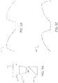
FIG. 2 is a schematic depiction of a wheel speed system having a variable inductor sensor, in accordance with various embodiments; -
FIG. 3A is schematic depiction of a first circumferential tooth array and a second circumferential tooth array of a variable inductor sensor; -
FIG. 3B is schematic depiction of a first circumferential tooth array and a second circumferential tooth array of a variable inductor sensor; -
FIG. 4A is a schematic depiction of a first individual tooth of a first circumferential tooth array and a second individual tooth of a second circumferential tooth array that, if implemented in a variable inductor sensor in place of the teeth shown inFIGS. 3A and 3B , would provide a variable inductor direction sensor, in accordance with the claimed invention; -
FIG. 4B is an expected first inductance waveform envelope shape in response to rotation of the first individual tooth ofFIG. 4A in a first direction, in accordance with various embodiments; -
FIG. 4C is an expected second inductance waveform envelope shape in response to rotation of the first individual tooth ofFIG. 4A in a second direction, in accordance with various embodiments; -
FIG. 5A is a schematic depiction of a first individual tooth of a first circumferential tooth array and a second individual tooth of a second circumferential tooth array, in accordance with alternatives which are not embodiments of the claimed invention; -
FIG. 5B is an expected first inductance waveform envelope shape in response to rotation of the first individual tooth ofFIG. 5A in a first direction; -
FIG. 5C is an expected second inductance waveform envelope shape in response to rotation of the first individual tooth ofFIG. 5A in a second direction; -
FIG. 6A is a schematic depiction of an inner circular body and an outer circular body, in accordance with various alternatives which are not embodiments of the claimed invention; -
FIG. 6B is an expected first inductance waveform envelope shape in response to rotation of the inner circular body ofFIG. 6A in a first direction; -
FIG. 6C is an expected second inductance waveform envelope shape in response to rotation of the inner circular body ofFIG. 6A in a second direction; -
FIG. 7A is a schematic depiction of a portion of a first circumferential tooth array and a portion of a second circumferential tooth array, in accordance with various alternatives which are not embodiments of the claimed invention; -
FIG. 7B is an expected first inductance waveform envelope shape in response to rotation of the first circumferential tooth array ofFIG. 7A in a first direction; and -
FIG. 7C is an expected second inductance waveform envelope shape in response to rotation of the first circumferential tooth array ofFIG. 7A in a second direction. - The subject matter of the present disclosure is particularly pointed out and distinctly claimed in the concluding portion of the specification. A more complete understanding of the present disclosure, however, may best be obtained by referring to the detailed description and claims when considered in connection with the drawing figures, wherein like numerals denote like elements.
- The detailed description of exemplary embodiments herein makes reference to the accompanying drawings, which show exemplary embodiments by way of illustration. While these exemplary embodiments are described in sufficient detail to enable those skilled in the art to practice the disclosure, it should be understood that other embodiments may be realized and that logical changes and adaptations in design and construction may be made in accordance with this disclosure and the teachings herein without departing from the scope of the invention as defined by the claims. Thus, the detailed description herein is presented for purposes of illustration only and not of limitation.
- Referring now to
FIG. 1 , in accordance with various embodiments, anaircraft 10 may include a wheel and brake system that includes one or more landing gear that may have one or more wheels and brakes (configurations may also include wheels without brakes). For example, theaircraft 10 may include leftmain landing gear 12, rightmain landing gear 14, andnose landing gear 16. Leftmain landing gear 12, rightmain landing gear 14, andnose landing gear 16 may generally supportaircraft 10 whenaircraft 10 is not flying, allowingaircraft 10 to taxi, take off and land without damage. Leftmain landing gear 12 may includewheel 13A and wheel 13B coupled by anaxle 20. Rightmain landing gear 14 may includewheel 15A and wheel 15B coupled by anaxle 22.Nose landing gear 16 may includenose wheel 17A and nose wheel 17B coupled by anaxle 24. In various embodiments,aircraft 10 may comprise any number of landing gears and each landing gear may comprise any number of wheels. Leftmain landing gear 12, rightmain landing gear 14, andnose landing gear 16 may each be retracted for flight. The landing gear may extend from an underside of thefuselage 28 or from an underside of thewings 30. -
Aircraft 10 may also include a brake assembly which may be applied to a wheel of a landing gear. The brake assembly ofaircraft 10 may comprise a collection of units and/or subassemblies that produce a braking force and/or torque applied at each wheel (e.g.,wheel 13A, wheel 13B,wheel 15A, wheel 15B, etc.). A brake system may communicate with the brakes of each landing gear (e.g., leftmain landing gear 12, rightmain landing gear 14, and/or nose landing gear 16), and brake assemblies may be mounted to each wheel to apply and release braking force on one or more wheels. The brake assemblies of anaircraft 10 may include a nonrotatable wheel support, a wheel (e.g.,wheel 13A, wheel 13B,wheel 15A, wheel 15B,wheel 17A, and/or wheel 17B) mounted to the wheel support for rotation, and a brake disk stack. - In various embodiments, and with reference to
FIG. 2 , a wheeldirection detection system 100 is provided. The wheeldirection detection system 100 includes, according to various embodiments, a variableinductor direction sensor 110 and acontrol unit 130. The variableinductor direction sensor 110 includes, according to various embodiments arotatable body 112 and astationary body 114. In various embodiments, and with reference toFIGS. 2, 3A, and 3B , therotatable body 112 has a gear-like structure and includes a firstcircumferential tooth array 113 and thestationary body 114 also has a gear-like structure and includes a secondcircumferential tooth array 115. In various embodiments, first andsecond tooth arrays second tooth arrays axis 105. In various embodiments,axis 105 is the rotational axis about which therotatable body 112 rotates. In various embodiments, therotatable body 112 is coupled to a an aircraft wheel via arotating shaft 111, an interfacing clip, a hub cap mounted to the wheel, or other such mechanism for syncing rotation with the aircraft wheel. - While the
rotatable body 112 is shown inFIGS. 2, 3A, and 3B as being radially inward of thestationary body 114 and thestationary body 114 is shown inFIGS. 2, 3A, and 3B as being radially outward of therotatable body 112, in the opposite configuration may be implemented. In other words, in various embodiments the rotatable body is the outer body and the stationary body is the inner body. Accordingly, the rotatable body of the variableinductor direction sensor 110 is disposed relative to the stationary body such that one of the first circumferential tooth array and the second circumferential tooth array circumscribes the other of the first circumferential tooth array and the second circumferential tooth array. - Said differently, the variable
inductor direction sensor 110 may include an inner circular body, such asrotatable body 112, that has a radially outward surface, such as 113, and the variableinductor direction sensor 110 may also include an outer circular body, such asstationary body 114, that has a radially inward surface, such as 115. In various embodiments, the outer circular body circumscribes the inner circular body such that the radially outward surface and the radially inward surface are concentric aboutaxis 105. Thus, according to various embodiments, one of the inner circular body and the outer circular body is rotatable about theaxis 105 and the other is stationary about the axis. - The
rotatable body 112 and thestationary body 114 may be made from a ferrous magnetic material, such as an iron oxide ceramic material, and thus therotatable body 112 and thestationary body 114 may form a single inductor that changes in inductance as the two different core pieces change in their alignments. Said differently, agap 116, such as an annular-like air gap, may be defined between therotatable body 112 and thestationary body 114, and a voltage drop across theinductor bodies gap 116. Accordingly, in order to not only determine the rotational speed of theshaft 111 but also the rotational direction of theshaft 111 coupled to the rotatable body 112 (and thus the direction of rotation of the wheel(s)), according to the claimed invention both a the firstcircumferential tooth array 113 and the secondcircumferential tooth array 115 have a non-uniform circumferential geometry. That is, both the radially outward surface of the inner circular body and the radially inward surface of the outer circular body have geometry/shape that varies non-uniformly in response to relative rotation between the two bodies. This dimensional variation in the circumferential direction of one or both of the surfaces of the bodies that define the annular-like gap 116 enable thecontrol unit 130 to determine, based on the voltage drop, the speed and direction of rotation of the rotatable body. As described in greater detail below, this non-uniform circumferential geometry comprises an asymmetrical tooth geometry of individual teeth of the respective arrays of teeth. These non-uniformities may extend around the entire circumference of the respective bodies, or the non-uniformities may extend along a circumferential portion of the respective bodies. - In various embodiments, and with reference to
FIGS. 4A, 4B, and 4C , the non-uniform circumferential geometry is embodied by individual teeth having asymmetrical geometries.FIG. 4A shows, according to various embodiments, both a firstindividual tooth 213 of the first circumferential tooth array of the rotatable body having an asymmetrical tooth geometry and a secondindividual tooth 215 of the second circumferential tooth array of the stationary body having an asymmetrical tooth geometry. Theseteeth radial axis 205. For example,tooth 215 may have afirst surface 218 on a first side of theradial axis 205 that is substantially perpendicular to theradial axis 205 and asecond surface 219 on a second side of theradial axis 205 that extends radially relative to thefirst surface 218. The asymmetrical geometry of theteeth like gap 216 produce a directionally specific pattern of repeated alignment and misalignment of the respective teeth, which changes the inductance value (e.g., a voltage drop) of the sensor. This inductance value, also referred to herein as an inductance waveform envelope shape, is dependent on the dimension of the annular-like gap 216. Thus, in response to rotation of the first tooth 213 (e.g., the rotatable body) in afirst direction 221, thecontrol unit 130 may detect the voltage drop as the first inductancewaveform envelope shape 231 shown inFIG. 4B . Similarly, in response to rotation of the first tooth 213 (e.g., the rotatable body) in asecond direction 222 opposite thefirst direction 221, thecontrol unit 130 may detect the voltage drop as the second inductancewaveform envelope shape 232 shown inFIG. 4C . The unique shape/geometry of resultant inductance waveforms is direction specific, thus allowing thecontrol unit 130 to determine the rotation direction of the rotatable shaft 111 (e.g., wheel). - In various alternatives which are not embodiments of the claimed invention, and with reference to
FIGS. 5A, 5B, and 5C , a firstindividual tooth 313 of the first circumferential tooth array of the rotatable body has an asymmetrical tooth geometry and a secondindividual tooth 315 of the second circumferential tooth array of the stationary body has a symmetrical geometry. The asymmetrical geometry ofteeth 313 creates a annular-like gap 316 that has a varying dimension. Accordingly, in response to rotation of the first tooth 313 (e.g., the rotatable body) indirection 321, thecontrol unit 130 may detect the voltage drop as the first inductancewaveform envelope shape 331 shown inFIG. 5B . Similarly, in response to rotation of the first tooth 313 (e.g., the rotatable body) insecond direction 322 opposite thefirst direction 321, thecontrol unit 130 may detect the voltage drop as the second inductance waveform envelope shape 332 shown inFIG. 5C . The unique shape/geometry of resultant inductance waveforms is direction specific, thus allowing thecontrol unit 130 to determine the rotation direction of the rotatable shaft 111 (e.g., wheel). - In various alternatives which are not embodiments of the claimed invention, and with reference to
FIGS. 6A, 6B, and 6C , the non-uniform circumferential geometry is embodied by at least one of the first circumferential tooth array and the second circumferential tooth array having an irregular sequential pattern of teeth along at least a circumferential portion of the one of the first circumferential tooth array and the second circumferential tooth array. That is, the variation in the size of gap between the first circumferential tooth array and the second circumferential tooth array is dependent on the relative directional rotation tooth arrays. Accordingly, radiallyinward surface 415 of the outercircular body 414 may have abrupt steps that cause the dimension of the annular-like gap 416 to vary in response to relative rotation between the twobodies gap 416 defined between the radiallyoutward surface 413 of the innercircular body 412 and the radiallyinward surface 415 of the outercircular body 414 may be defined as a dimension variation profile. Accordingly, in response to rotation of the rotatable one of the innercircular body 412 and the outercircular body 414 in thefirst direction 421 about the axis 105 (FIG. 2 ), the first dimension variation profile of thegap 416 corresponds to a first inductancewaveform envelope shape 431. Similarly, in response to rotation of the rotatable one of the innercircular body 412 and the outercircular body 414 in thesecond direction 422 about the axis 105 (FIG. 2 ), the second dimension variation profile of thegap 416 corresponds to a second inductancewaveform envelope shape 432. The unique shape/geometry ofresultant inductance waveforms control unit 130 to determine the rotation direction of the rotatable shaft 111 (e.g., wheel axle). - In various alternatives which are not embodiments of the claimed invention, and with reference to
FIGS. 7A, 7B, and 7C , the non-uniform circumferential geometry is embodied by at least one of the first circumferential tooth array and the second circumferential tooth array having an irregular sequential pattern of teeth along at least a circumferential portion of the one of the first circumferential tooth array and the second circumferential tooth array. Accordingly, radiallyinward surface 515 of the outercircular body 514 may have uniform spacing and tooth geometry while radiallyoutward surface 513 of the innercircular body 512 may have an irregular sequential pattern of teeth. Accordingly, in response to rotation of the rotatable one of the innercircular body 512 and the outercircular body 514 in thefirst direction 521 about the axis 105 (FIG. 2 ), the first dimension variation profile of thegap 516 corresponds to a first inductancewaveform envelope shape 531. Similarly, in response to rotation of the rotatable one of the innercircular body 512 and the outercircular body 514 in thesecond direction 522 about the axis 105 (FIG. 2 ), the second dimension variation profile of thegap 516 corresponds to a second inductancewaveform envelope shape 532. The unique shape/geometry ofresultant inductance waveforms control unit 130 to determine the rotation direction of the rotatable shaft 111 (e.g., wheel axle). - Benefits, other advantages, and solutions to problems have been described herein with regard to specific embodiments. Furthermore, the connecting lines shown in the various figures contained herein are intended to represent exemplary functional relationships and/or physical couplings between the various elements. It should be noted that many alternative or additional functional relationships or physical connections may be present in a practical system. However, the benefits, advantages, solutions to problems, and any elements that may cause any benefit, advantage, or solution to occur or become more pronounced are not to be construed as critical, required, or essential features or elements of the disclosure.
- The scope of the disclosure is accordingly to be limited by nothing other than the appended claims, in which reference to an element in the singular is not intended to mean "one and only one" unless explicitly so stated, but rather "one or more." It is to be understood that unless specifically stated otherwise, references to "a," "an," and/or "the" may include one or more than one and that reference to an item in the singular may also include the item in the plural. All ranges and ratio limits disclosed herein may be combined.
- Moreover, where a phrase similar to "at least one of A, B, and C" is used in the claims, it is intended that the phrase be interpreted to mean that A alone may be present in an embodiment, B alone may be present in an embodiment, C alone may be present in an embodiment, or that any combination of the elements A, B and C may be present in a single embodiment; for example, A and B, A and C, B and C, or A and B and C. Different cross-hatching is used throughout the figures to denote different parts but not necessarily to denote the same or different materials.
- The steps recited in any of the method or process descriptions may be executed in any order and are not necessarily limited to the order presented. Furthermore, any reference to singular includes plural embodiments, and any reference to more than one component or step may include a singular embodiment or step. Elements and steps in the figures are illustrated for simplicity and clarity and have not necessarily been rendered according to any particular sequence. For example, steps that may be performed concurrently or in different order are illustrated in the figures to help to improve understanding of embodiments of the present disclosure.
- Any reference to attached, fixed, connected or the like may include permanent, removable, temporary, partial, full and/or any other possible attachment option. Additionally, any reference to without contact (or similar phrases) may also include reduced contact or minimal contact. Surface shading lines may be used throughout the figures to denote different parts or areas but not necessarily to denote the same or different materials. In some cases, reference coordinates may be specific to each figure.
- Systems, methods and apparatus are provided herein. In the detailed description herein, references to "one embodiment," "an embodiment," "various embodiments," etc., indicate that the embodiment described may include a particular feature, structure, or characteristic, but every embodiment may not necessarily include the particular feature, structure, or characteristic. Moreover, such phrases are not necessarily referring to the same embodiment. Further, when a particular feature, structure, or characteristic is described in connection with an embodiment, it is submitted that it is within the knowledge of one skilled in the art to affect such feature, structure, or characteristic in connection with other embodiments whether or not explicitly described. After reading the description, it will be apparent to one skilled in the relevant art(s) how to implement the disclosure in alternative embodiments, as long as they are covered by the claims.
Claims (5)
- A variable inductor direction sensor comprising:a rotatable body (112) comprising a first circumferential tooth array (113); anda stationary body (114) comprising a second circumferential tooth array (115) concentric with the first circumferential tooth array;wherein the rotatable body is disposed relative to the stationary body such that one of the first circumferential tooth array and the second circumferential tooth array circumscribes the other of the first circumferential tooth array and the second circumferential tooth array;wherein each of the first circumferential tooth array and the second circumferential tooth array comprises teeth that are asymmetrical about a radial axis along at least a circumferential portion of the at least one of the first circumferential tooth array and the second circumferential tooth array.
- The variable inductor direction sensor of claim 1, wherein each tooth of the teeth that are asymmetrical comprises a first surface on a first side of the radial axis that is substantially perpendicular to the radial axis and a second surface on a second side of the radial axis that extends radially relative to the first surface.
- The variable inductor direction sensor of any preceding claim, wherein an annular-like gap (116) is defined between the first circumferential tooth array and the second circumferential tooth array.
- The variable inductor direction sensor of any preceding claim, wherein the rotatable body is coupled to a rotating shaft of an aircraft wheel (13, 15).
- A wheel direction detection system comprising:a variable inductor direction sensor (110) as claimed in any preceding claim, wherein the rotatable body is coupled to a rotating shaft of a wheel; anda control unit (130) electrically coupled to the variable inductor direction sensor, wherein the control unit is configured to determine a direction of rotation of the rotatable body based on a detected inductance waveform envelope shape.
Priority Applications (1)
| Application Number | Priority Date | Filing Date | Title |
|---|---|---|---|
| EP22183422.9A EP4109109A1 (en) | 2017-09-22 | 2018-09-20 | Wheel speed and direction sensor |
Applications Claiming Priority (1)
| Application Number | Priority Date | Filing Date | Title |
|---|---|---|---|
| US15/712,718 US10584965B2 (en) | 2017-09-22 | 2017-09-22 | Wheel speed and direction sensor |
Related Child Applications (1)
| Application Number | Title | Priority Date | Filing Date |
|---|---|---|---|
| EP22183422.9A Division EP4109109A1 (en) | 2017-09-22 | 2018-09-20 | Wheel speed and direction sensor |
Publications (3)
| Publication Number | Publication Date |
|---|---|
| EP3460487A2 EP3460487A2 (en) | 2019-03-27 |
| EP3460487A3 EP3460487A3 (en) | 2019-06-19 |
| EP3460487B1 true EP3460487B1 (en) | 2022-08-03 |
Family
ID=63713607
Family Applications (2)
| Application Number | Title | Priority Date | Filing Date |
|---|---|---|---|
| EP18195734.1A Active EP3460487B1 (en) | 2017-09-22 | 2018-09-20 | Wheel rotational direction sensor |
| EP22183422.9A Pending EP4109109A1 (en) | 2017-09-22 | 2018-09-20 | Wheel speed and direction sensor |
Family Applications After (1)
| Application Number | Title | Priority Date | Filing Date |
|---|---|---|---|
| EP22183422.9A Pending EP4109109A1 (en) | 2017-09-22 | 2018-09-20 | Wheel speed and direction sensor |
Country Status (2)
| Country | Link |
|---|---|
| US (1) | US10584965B2 (en) |
| EP (2) | EP3460487B1 (en) |
Families Citing this family (1)
| Publication number | Priority date | Publication date | Assignee | Title |
|---|---|---|---|---|
| US10584965B2 (en) * | 2017-09-22 | 2020-03-10 | Goodrich Corporation | Wheel speed and direction sensor |
Family Cites Families (15)
| Publication number | Priority date | Publication date | Assignee | Title |
|---|---|---|---|---|
| DE2045917A1 (en) | 1970-09-17 | 1972-03-23 | Teldix Gmbh | |
| US3739211A (en) | 1971-10-15 | 1973-06-12 | Amper Corp | Magnetic tachometer |
| JPS5731353A (en) * | 1980-07-31 | 1982-02-19 | Matsushita Electric Ind Co Ltd | Speed detector for sewing machine |
| JPH063457B2 (en) * | 1982-02-25 | 1994-01-12 | 三菱電機株式会社 | Rotation direction detector |
| US5223760A (en) * | 1988-08-24 | 1993-06-29 | Rockwell International Corporation | Wheel speed sensor for drive axle |
| FR2648563B1 (en) * | 1989-06-20 | 1993-01-22 | Crouzet Sa | DEVICE FOR DETERMINING THE DIRECTION OF MOVEMENT OF A MOBILE OBJECT |
| US5491407A (en) | 1995-02-03 | 1996-02-13 | Kearney-National, Inc. | Wheel bearing speed sensor |
| US6650110B2 (en) | 2001-06-04 | 2003-11-18 | Delphi Technologies, Inc. | Target wheel sensor assembly for producing an asymmetric signal and for determining the direction of motion of the target wheel based on the signal shape |
| DE10133381A1 (en) | 2001-07-10 | 2003-01-23 | Bayerische Motoren Werke Ag | Device for detecting speed, direction of motion of body, e.g. rotating shaft, has asymmetrical trigger so that signal recorded by signal pick-up is different according to direction of movement of body |
| US7116096B2 (en) | 2003-08-13 | 2006-10-03 | Bendix Commercial Vehicle Systems Llc | Vehicle direction detection using tone ring |
| DE102004059165A1 (en) * | 2004-12-08 | 2006-06-14 | Siemens Ag | Method for determination of direction of rotation of moving wheel involves certain steps such as formation of capacitor with a pair of electrode and collection of series of changes in capacitor and determination of direction of rotation |
| DE102009020594A1 (en) | 2008-11-08 | 2010-05-20 | Wabco Gmbh | Method for determining a direction of travel and control device for a vehicle system |
| US9482686B2 (en) | 2013-03-13 | 2016-11-01 | Woodward, Inc. | Aircraft wheel speed sensor |
| US10584965B2 (en) * | 2017-09-22 | 2020-03-10 | Goodrich Corporation | Wheel speed and direction sensor |
| JP6518802B1 (en) * | 2018-02-28 | 2019-05-22 | J−Net株式会社 | Third party management system for ball storage data, game arcade system, computer program |
-
2017
- 2017-09-22 US US15/712,718 patent/US10584965B2/en active Active
-
2018
- 2018-09-20 EP EP18195734.1A patent/EP3460487B1/en active Active
- 2018-09-20 EP EP22183422.9A patent/EP4109109A1/en active Pending
Also Published As
| Publication number | Publication date |
|---|---|
| US10584965B2 (en) | 2020-03-10 |
| EP3460487A2 (en) | 2019-03-27 |
| US20190094020A1 (en) | 2019-03-28 |
| EP4109109A1 (en) | 2022-12-28 |
| EP3460487A3 (en) | 2019-06-19 |
Similar Documents
| Publication | Publication Date | Title |
|---|---|---|
| EP2684752B1 (en) | Method for dragging brake detection | |
| US10967961B2 (en) | Laminated dimpled foil metallic heat shield | |
| EP3480072B1 (en) | Shield attachment device | |
| JP4277799B2 (en) | Vehicle control system | |
| EP0438624B1 (en) | Device enabling the revolutionary speed to be measured between the races of a rolling bearing for the support of a vehicle wheel | |
| JP2011514862A (en) | Outer hub barrel mounting rotor | |
| EP4140881B1 (en) | Retainer for segmented annular heat shield | |
| US10837823B2 (en) | Aircraft landing gear | |
| US10584965B2 (en) | Wheel speed and direction sensor | |
| EP3159179A2 (en) | Mismatch side rim and lock ring interface angles for lock ring wheel | |
| US10598681B2 (en) | Wheel speed sensor | |
| EP1780100A1 (en) | A method of manufacturing a steering knuckle corner assembly | |
| EP3524517B1 (en) | Insulated torque plate foot assembly | |
| US20200325948A1 (en) | Multiple layer piston insulator for hydraulic brake actuator | |
| CN106945461B (en) | Hub for a bicycle wheel | |
| CN210199133U (en) | Automobile redundant wheel speed detection system | |
| US20190120302A1 (en) | Torque plate barrel having blended barrel support pedestal | |
| EP3441637A1 (en) | Differential torque plate barrel thickness | |
| US10473488B2 (en) | Magnetic measurement target positioned inside a vehicle axle | |
| EP3184854B1 (en) | Aircraft axle insert to mitigate vibration | |
| US20250298049A1 (en) | Tachometer for an aircraft wheel | |
| CN205706645U (en) | The anti-lock brake system of steering and driving axle hub brake | |
| EP3184323B1 (en) | Brake axle sleeve | |
| JPH01237249A (en) | Bearing unit for wheels | |
| EP3878663A1 (en) | Wheel assembly with exterior fuse plug |
Legal Events
| Date | Code | Title | Description |
|---|---|---|---|
| PUAI | Public reference made under article 153(3) epc to a published international application that has entered the european phase |
Free format text: ORIGINAL CODE: 0009012 |
|
| STAA | Information on the status of an ep patent application or granted ep patent |
Free format text: STATUS: THE APPLICATION HAS BEEN PUBLISHED |
|
| AK | Designated contracting states |
Kind code of ref document: A2 Designated state(s): AL AT BE BG CH CY CZ DE DK EE ES FI FR GB GR HR HU IE IS IT LI LT LU LV MC MK MT NL NO PL PT RO RS SE SI SK SM TR |
|
| AX | Request for extension of the european patent |
Extension state: BA ME |
|
| PUAL | Search report despatched |
Free format text: ORIGINAL CODE: 0009013 |
|
| AK | Designated contracting states |
Kind code of ref document: A3 Designated state(s): AL AT BE BG CH CY CZ DE DK EE ES FI FR GB GR HR HU IE IS IT LI LT LU LV MC MK MT NL NO PL PT RO RS SE SI SK SM TR |
|
| AX | Request for extension of the european patent |
Extension state: BA ME |
|
| RIC1 | Information provided on ipc code assigned before grant |
Ipc: G01D 5/20 20060101ALI20190514BHEP Ipc: G01P 3/488 20060101AFI20190514BHEP Ipc: G01P 13/04 20060101ALI20190514BHEP |
|
| STAA | Information on the status of an ep patent application or granted ep patent |
Free format text: STATUS: REQUEST FOR EXAMINATION WAS MADE |
|
| 17P | Request for examination filed |
Effective date: 20191219 |
|
| RBV | Designated contracting states (corrected) |
Designated state(s): AL AT BE BG CH CY CZ DE DK EE ES FI FR GB GR HR HU IE IS IT LI LT LU LV MC MK MT NL NO PL PT RO RS SE SI SK SM TR |
|
| STAA | Information on the status of an ep patent application or granted ep patent |
Free format text: STATUS: EXAMINATION IS IN PROGRESS |
|
| 17Q | First examination report despatched |
Effective date: 20210216 |
|
| GRAP | Despatch of communication of intention to grant a patent |
Free format text: ORIGINAL CODE: EPIDOSNIGR1 |
|
| STAA | Information on the status of an ep patent application or granted ep patent |
Free format text: STATUS: GRANT OF PATENT IS INTENDED |
|
| INTG | Intention to grant announced |
Effective date: 20220224 |
|
| GRAS | Grant fee paid |
Free format text: ORIGINAL CODE: EPIDOSNIGR3 |
|
| GRAA | (expected) grant |
Free format text: ORIGINAL CODE: 0009210 |
|
| STAA | Information on the status of an ep patent application or granted ep patent |
Free format text: STATUS: THE PATENT HAS BEEN GRANTED |
|
| AK | Designated contracting states |
Kind code of ref document: B1 Designated state(s): AL AT BE BG CH CY CZ DE DK EE ES FI FR GB GR HR HU IE IS IT LI LT LU LV MC MK MT NL NO PL PT RO RS SE SI SK SM TR |
|
| REG | Reference to a national code |
Ref country code: AT Ref legal event code: REF Ref document number: 1509155 Country of ref document: AT Kind code of ref document: T Effective date: 20220815 Ref country code: CH Ref legal event code: EP |
|
| REG | Reference to a national code |
Ref country code: DE Ref legal event code: R096 Ref document number: 602018038681 Country of ref document: DE |
|
| REG | Reference to a national code |
Ref country code: IE Ref legal event code: FG4D |
|
| REG | Reference to a national code |
Ref country code: LT Ref legal event code: MG9D |
|
| REG | Reference to a national code |
Ref country code: NL Ref legal event code: MP Effective date: 20220803 |
|
| PG25 | Lapsed in a contracting state [announced via postgrant information from national office to epo] |
Ref country code: SE Free format text: LAPSE BECAUSE OF FAILURE TO SUBMIT A TRANSLATION OF THE DESCRIPTION OR TO PAY THE FEE WITHIN THE PRESCRIBED TIME-LIMIT Effective date: 20220803 Ref country code: RS Free format text: LAPSE BECAUSE OF FAILURE TO SUBMIT A TRANSLATION OF THE DESCRIPTION OR TO PAY THE FEE WITHIN THE PRESCRIBED TIME-LIMIT Effective date: 20220803 Ref country code: PT Free format text: LAPSE BECAUSE OF FAILURE TO SUBMIT A TRANSLATION OF THE DESCRIPTION OR TO PAY THE FEE WITHIN THE PRESCRIBED TIME-LIMIT Effective date: 20221205 Ref country code: NO Free format text: LAPSE BECAUSE OF FAILURE TO SUBMIT A TRANSLATION OF THE DESCRIPTION OR TO PAY THE FEE WITHIN THE PRESCRIBED TIME-LIMIT Effective date: 20221103 Ref country code: NL Free format text: LAPSE BECAUSE OF FAILURE TO SUBMIT A TRANSLATION OF THE DESCRIPTION OR TO PAY THE FEE WITHIN THE PRESCRIBED TIME-LIMIT Effective date: 20220803 Ref country code: LV Free format text: LAPSE BECAUSE OF FAILURE TO SUBMIT A TRANSLATION OF THE DESCRIPTION OR TO PAY THE FEE WITHIN THE PRESCRIBED TIME-LIMIT Effective date: 20220803 Ref country code: LT Free format text: LAPSE BECAUSE OF FAILURE TO SUBMIT A TRANSLATION OF THE DESCRIPTION OR TO PAY THE FEE WITHIN THE PRESCRIBED TIME-LIMIT Effective date: 20220803 Ref country code: FI Free format text: LAPSE BECAUSE OF FAILURE TO SUBMIT A TRANSLATION OF THE DESCRIPTION OR TO PAY THE FEE WITHIN THE PRESCRIBED TIME-LIMIT Effective date: 20220803 Ref country code: ES Free format text: LAPSE BECAUSE OF FAILURE TO SUBMIT A TRANSLATION OF THE DESCRIPTION OR TO PAY THE FEE WITHIN THE PRESCRIBED TIME-LIMIT Effective date: 20220803 |
|
| REG | Reference to a national code |
Ref country code: AT Ref legal event code: MK05 Ref document number: 1509155 Country of ref document: AT Kind code of ref document: T Effective date: 20220803 |
|
| PG25 | Lapsed in a contracting state [announced via postgrant information from national office to epo] |
Ref country code: PL Free format text: LAPSE BECAUSE OF FAILURE TO SUBMIT A TRANSLATION OF THE DESCRIPTION OR TO PAY THE FEE WITHIN THE PRESCRIBED TIME-LIMIT Effective date: 20220803 Ref country code: IS Free format text: LAPSE BECAUSE OF FAILURE TO SUBMIT A TRANSLATION OF THE DESCRIPTION OR TO PAY THE FEE WITHIN THE PRESCRIBED TIME-LIMIT Effective date: 20221203 Ref country code: HR Free format text: LAPSE BECAUSE OF FAILURE TO SUBMIT A TRANSLATION OF THE DESCRIPTION OR TO PAY THE FEE WITHIN THE PRESCRIBED TIME-LIMIT Effective date: 20220803 Ref country code: GR Free format text: LAPSE BECAUSE OF FAILURE TO SUBMIT A TRANSLATION OF THE DESCRIPTION OR TO PAY THE FEE WITHIN THE PRESCRIBED TIME-LIMIT Effective date: 20221104 |
|
| REG | Reference to a national code |
Ref country code: DE Ref legal event code: R119 Ref document number: 602018038681 Country of ref document: DE |
|
| PG25 | Lapsed in a contracting state [announced via postgrant information from national office to epo] |
Ref country code: SM Free format text: LAPSE BECAUSE OF FAILURE TO SUBMIT A TRANSLATION OF THE DESCRIPTION OR TO PAY THE FEE WITHIN THE PRESCRIBED TIME-LIMIT Effective date: 20220803 Ref country code: RO Free format text: LAPSE BECAUSE OF FAILURE TO SUBMIT A TRANSLATION OF THE DESCRIPTION OR TO PAY THE FEE WITHIN THE PRESCRIBED TIME-LIMIT Effective date: 20220803 Ref country code: DK Free format text: LAPSE BECAUSE OF FAILURE TO SUBMIT A TRANSLATION OF THE DESCRIPTION OR TO PAY THE FEE WITHIN THE PRESCRIBED TIME-LIMIT Effective date: 20220803 Ref country code: CZ Free format text: LAPSE BECAUSE OF FAILURE TO SUBMIT A TRANSLATION OF THE DESCRIPTION OR TO PAY THE FEE WITHIN THE PRESCRIBED TIME-LIMIT Effective date: 20220803 Ref country code: AT Free format text: LAPSE BECAUSE OF FAILURE TO SUBMIT A TRANSLATION OF THE DESCRIPTION OR TO PAY THE FEE WITHIN THE PRESCRIBED TIME-LIMIT Effective date: 20220803 |
|
| REG | Reference to a national code |
Ref country code: CH Ref legal event code: PL |
|
| REG | Reference to a national code |
Ref country code: BE Ref legal event code: MM Effective date: 20220930 |
|
| PG25 | Lapsed in a contracting state [announced via postgrant information from national office to epo] |
Ref country code: SK Free format text: LAPSE BECAUSE OF FAILURE TO SUBMIT A TRANSLATION OF THE DESCRIPTION OR TO PAY THE FEE WITHIN THE PRESCRIBED TIME-LIMIT Effective date: 20220803 Ref country code: MC Free format text: LAPSE BECAUSE OF FAILURE TO SUBMIT A TRANSLATION OF THE DESCRIPTION OR TO PAY THE FEE WITHIN THE PRESCRIBED TIME-LIMIT Effective date: 20220803 Ref country code: EE Free format text: LAPSE BECAUSE OF FAILURE TO SUBMIT A TRANSLATION OF THE DESCRIPTION OR TO PAY THE FEE WITHIN THE PRESCRIBED TIME-LIMIT Effective date: 20220803 |
|
| PLBE | No opposition filed within time limit |
Free format text: ORIGINAL CODE: 0009261 |
|
| STAA | Information on the status of an ep patent application or granted ep patent |
Free format text: STATUS: NO OPPOSITION FILED WITHIN TIME LIMIT |
|
| P01 | Opt-out of the competence of the unified patent court (upc) registered |
Effective date: 20230521 |
|
| PG25 | Lapsed in a contracting state [announced via postgrant information from national office to epo] |
Ref country code: LU Free format text: LAPSE BECAUSE OF NON-PAYMENT OF DUE FEES Effective date: 20220920 Ref country code: AL Free format text: LAPSE BECAUSE OF FAILURE TO SUBMIT A TRANSLATION OF THE DESCRIPTION OR TO PAY THE FEE WITHIN THE PRESCRIBED TIME-LIMIT Effective date: 20220803 |
|
| 26N | No opposition filed |
Effective date: 20230504 |
|
| PG25 | Lapsed in a contracting state [announced via postgrant information from national office to epo] |
Ref country code: LI Free format text: LAPSE BECAUSE OF NON-PAYMENT OF DUE FEES Effective date: 20220930 Ref country code: IE Free format text: LAPSE BECAUSE OF NON-PAYMENT OF DUE FEES Effective date: 20220920 Ref country code: DE Free format text: LAPSE BECAUSE OF NON-PAYMENT OF DUE FEES Effective date: 20230401 Ref country code: CH Free format text: LAPSE BECAUSE OF NON-PAYMENT OF DUE FEES Effective date: 20220930 |
|
| PG25 | Lapsed in a contracting state [announced via postgrant information from national office to epo] |
Ref country code: SI Free format text: LAPSE BECAUSE OF FAILURE TO SUBMIT A TRANSLATION OF THE DESCRIPTION OR TO PAY THE FEE WITHIN THE PRESCRIBED TIME-LIMIT Effective date: 20220803 |
|
| PG25 | Lapsed in a contracting state [announced via postgrant information from national office to epo] |
Ref country code: BE Free format text: LAPSE BECAUSE OF NON-PAYMENT OF DUE FEES Effective date: 20220930 |
|
| PG25 | Lapsed in a contracting state [announced via postgrant information from national office to epo] |
Ref country code: HU Free format text: LAPSE BECAUSE OF FAILURE TO SUBMIT A TRANSLATION OF THE DESCRIPTION OR TO PAY THE FEE WITHIN THE PRESCRIBED TIME-LIMIT; INVALID AB INITIO Effective date: 20180920 |
|
| PG25 | Lapsed in a contracting state [announced via postgrant information from national office to epo] |
Ref country code: CY Free format text: LAPSE BECAUSE OF FAILURE TO SUBMIT A TRANSLATION OF THE DESCRIPTION OR TO PAY THE FEE WITHIN THE PRESCRIBED TIME-LIMIT Effective date: 20220803 |
|
| PG25 | Lapsed in a contracting state [announced via postgrant information from national office to epo] |
Ref country code: MK Free format text: LAPSE BECAUSE OF FAILURE TO SUBMIT A TRANSLATION OF THE DESCRIPTION OR TO PAY THE FEE WITHIN THE PRESCRIBED TIME-LIMIT Effective date: 20220803 Ref country code: IT Free format text: LAPSE BECAUSE OF FAILURE TO SUBMIT A TRANSLATION OF THE DESCRIPTION OR TO PAY THE FEE WITHIN THE PRESCRIBED TIME-LIMIT Effective date: 20220803 |
|
| PG25 | Lapsed in a contracting state [announced via postgrant information from national office to epo] |
Ref country code: TR Free format text: LAPSE BECAUSE OF FAILURE TO SUBMIT A TRANSLATION OF THE DESCRIPTION OR TO PAY THE FEE WITHIN THE PRESCRIBED TIME-LIMIT Effective date: 20220803 |
|
| PG25 | Lapsed in a contracting state [announced via postgrant information from national office to epo] |
Ref country code: BG Free format text: LAPSE BECAUSE OF FAILURE TO SUBMIT A TRANSLATION OF THE DESCRIPTION OR TO PAY THE FEE WITHIN THE PRESCRIBED TIME-LIMIT Effective date: 20220803 |
|
| PG25 | Lapsed in a contracting state [announced via postgrant information from national office to epo] |
Ref country code: MT Free format text: LAPSE BECAUSE OF FAILURE TO SUBMIT A TRANSLATION OF THE DESCRIPTION OR TO PAY THE FEE WITHIN THE PRESCRIBED TIME-LIMIT Effective date: 20220803 |
|
| PGFP | Annual fee paid to national office [announced via postgrant information from national office to epo] |
Ref country code: GB Payment date: 20250822 Year of fee payment: 8 |
|
| PGFP | Annual fee paid to national office [announced via postgrant information from national office to epo] |
Ref country code: FR Payment date: 20250821 Year of fee payment: 8 |