US5491407A - Wheel bearing speed sensor - Google Patents
Wheel bearing speed sensor Download PDFInfo
- Publication number
- US5491407A US5491407A US08/383,079 US38307995A US5491407A US 5491407 A US5491407 A US 5491407A US 38307995 A US38307995 A US 38307995A US 5491407 A US5491407 A US 5491407A
- Authority
- US
- United States
- Prior art keywords
- stator
- teeth
- rotor
- bobbin member
- wheel bearing
- Prior art date
- Legal status (The legal status is an assumption and is not a legal conclusion. Google has not performed a legal analysis and makes no representation as to the accuracy of the status listed.)
- Expired - Fee Related
Links
- 230000004907 flux Effects 0.000 claims abstract description 44
- 238000004804 winding Methods 0.000 claims abstract description 21
- 239000004020 conductor Substances 0.000 claims description 22
- 239000000463 material Substances 0.000 claims description 10
- 238000005096 rolling process Methods 0.000 claims description 3
- 230000001939 inductive effect Effects 0.000 abstract 1
- 230000035945 sensitivity Effects 0.000 description 5
- 230000000712 assembly Effects 0.000 description 4
- 238000000429 assembly Methods 0.000 description 4
- 238000000034 method Methods 0.000 description 4
- 229910000831 Steel Inorganic materials 0.000 description 2
- 239000000696 magnetic material Substances 0.000 description 2
- 238000004519 manufacturing process Methods 0.000 description 2
- 238000012986 modification Methods 0.000 description 2
- 230000004048 modification Effects 0.000 description 2
- 238000005476 soldering Methods 0.000 description 2
- 239000010959 steel Substances 0.000 description 2
- RYGMFSIKBFXOCR-UHFFFAOYSA-N Copper Chemical compound [Cu] RYGMFSIKBFXOCR-UHFFFAOYSA-N 0.000 description 1
- 230000004075 alteration Effects 0.000 description 1
- 230000008901 benefit Effects 0.000 description 1
- 230000008859 change Effects 0.000 description 1
- 238000010276 construction Methods 0.000 description 1
- 229910052802 copper Inorganic materials 0.000 description 1
- 239000010949 copper Substances 0.000 description 1
- 230000007246 mechanism Effects 0.000 description 1
- 239000002245 particle Substances 0.000 description 1
- 230000001737 promoting effect Effects 0.000 description 1
- 229910000859 α-Fe Inorganic materials 0.000 description 1
Images


Classifications
-
- B—PERFORMING OPERATIONS; TRANSPORTING
- B60—VEHICLES IN GENERAL
- B60B—VEHICLE WHEELS; CASTORS; AXLES FOR WHEELS OR CASTORS; INCREASING WHEEL ADHESION
- B60B27/00—Hubs
- B60B27/0047—Hubs characterised by functional integration of other elements
- B60B27/0068—Hubs characterised by functional integration of other elements the element being a sensor
-
- B—PERFORMING OPERATIONS; TRANSPORTING
- B60—VEHICLES IN GENERAL
- B60B—VEHICLE WHEELS; CASTORS; AXLES FOR WHEELS OR CASTORS; INCREASING WHEEL ADHESION
- B60B27/00—Hubs
- B60B27/0005—Hubs with ball bearings
-
- B—PERFORMING OPERATIONS; TRANSPORTING
- B60—VEHICLES IN GENERAL
- B60T—VEHICLE BRAKE CONTROL SYSTEMS OR PARTS THEREOF; BRAKE CONTROL SYSTEMS OR PARTS THEREOF, IN GENERAL; ARRANGEMENT OF BRAKING ELEMENTS ON VEHICLES IN GENERAL; PORTABLE DEVICES FOR PREVENTING UNWANTED MOVEMENT OF VEHICLES; VEHICLE MODIFICATIONS TO FACILITATE COOLING OF BRAKES
- B60T8/00—Arrangements for adjusting wheel-braking force to meet varying vehicular or ground-surface conditions, e.g. limiting or varying distribution of braking force
- B60T8/17—Using electrical or electronic regulation means to control braking
- B60T8/171—Detecting parameters used in the regulation; Measuring values used in the regulation
-
- G—PHYSICS
- G01—MEASURING; TESTING
- G01P—MEASURING LINEAR OR ANGULAR SPEED, ACCELERATION, DECELERATION, OR SHOCK; INDICATING PRESENCE, ABSENCE, OR DIRECTION, OF MOVEMENT
- G01P3/00—Measuring linear or angular speed; Measuring differences of linear or angular speeds
- G01P3/42—Devices characterised by the use of electric or magnetic means
- G01P3/44—Devices characterised by the use of electric or magnetic means for measuring angular speed
- G01P3/443—Devices characterised by the use of electric or magnetic means for measuring angular speed mounted in bearings
-
- G—PHYSICS
- G01—MEASURING; TESTING
- G01P—MEASURING LINEAR OR ANGULAR SPEED, ACCELERATION, DECELERATION, OR SHOCK; INDICATING PRESENCE, ABSENCE, OR DIRECTION, OF MOVEMENT
- G01P3/00—Measuring linear or angular speed; Measuring differences of linear or angular speeds
- G01P3/42—Devices characterised by the use of electric or magnetic means
- G01P3/44—Devices characterised by the use of electric or magnetic means for measuring angular speed
- G01P3/48—Devices characterised by the use of electric or magnetic means for measuring angular speed by measuring frequency of generated current or voltage
- G01P3/481—Devices characterised by the use of electric or magnetic means for measuring angular speed by measuring frequency of generated current or voltage of pulse signals
- G01P3/488—Devices characterised by the use of electric or magnetic means for measuring angular speed by measuring frequency of generated current or voltage of pulse signals delivered by variable reluctance detectors
-
- B—PERFORMING OPERATIONS; TRANSPORTING
- B60—VEHICLES IN GENERAL
- B60G—VEHICLE SUSPENSION ARRANGEMENTS
- B60G2204/00—Indexing codes related to suspensions per se or to auxiliary parts
- B60G2204/10—Mounting of suspension elements
- B60G2204/11—Mounting of sensors thereon
- B60G2204/115—Wheel hub bearing sensors
Definitions
- the present invention relates generally to automotive wheel bearing speed sensors and more specifically to such sensors using variable reluctance to measure wheel bearing rotational speeds for determining, for example, wheel lock or slippage.
- Bearing type wheel speed sensors are commonly used in brake control systems, antilock brake systems (ABS), traction control systems, differential lock-up systems and the like to provide a control signal representative of wheel rotational speed to a controller such as a microprocessor based electronic control unit.
- ABS antilock brake systems
- traction control systems traction control systems
- differential lock-up systems and the like to provide a control signal representative of wheel rotational speed to a controller such as a microprocessor based electronic control unit.
- a controller such as a microprocessor based electronic control unit.
- sensors are electromagnetic in nature and rely on a variable reluctance magnetic flux path to produce the wheel speed signal.
- Annular rotational speed sensor assemblies having multi-toothed stators which surround a similarly multi-toothed rotor, or vise versa, are known in the art. Annular multi-toothed assemblies are preferred for sensing low wheel rotational speeds since they tend to provide high sensitivity as well as high signal to noise ratios. Examples of such wheel speed sensors may be seen by reference to U.S. Pat. Nos. 5,111,098, 5,227,719, 5,281,911, 5,291,130 and 5,336,995.
- wheel bearing speed sensors Some problems encountered with prior art wheel bearing speed sensors include unwanted magnetic flux loss to the housing and bearing assemblies, inefficient flux transfer and low sensitivities under certain conditions. Prior art attempts at overcoming some of these problems have resulted in burdensomely complex fabrication and assembly techniques used to achieve desired performance characteristics. What is therefore needed is a simple, easily manufactured and low cost wheel bearing speed sensor which will, at the same time, provide desirable performance characteristics. Such a sensor should provide an efficient flux path, have minimal flux loss and have high sensitivity. In addition, the sensor should be easy and inexpensive to manufacture by maintaining structural simplicity and incorporating inexpensive materials.
- the wheel bearing speed sensor of the present invention overcomes many of the foregoing problems associated with similar prior art sensors. Minimal and inexpensive components are used to provide a highly efficient, low flux loss and highly sensitive wheel bearing speed sensor.
- a wheel bearing speed sensor comprises a vehicle axle spindle rotatable about an axis on a plurality of bearings within a wheel bearing housing, an annular rotor mounted to the spindle for rotation therewith, wherein one end of the rotor defines a plurality of teeth, and a stator assembly fixed to the wheel bearing housing.
- the stator assembly includes an annular stator having a plurality of teeth extending from one end thereof and an opposite end.
- An annular bobbin member has a plurality of conductor windings around the periphery thereof and is slidably received within the stator between the stator teeth and the opposite end of the stator.
- the bobbin member also includes means cooperative with the stator to restrict axial movement of the bobbin member toward the stator teeth.
- a magnet is received radially within the stator between the bobbin member and the opposite end of the stator.
- the magnet defines a magnetic pole along an outer surface thereof which is magnetically secured to an inner periphery of the stator adjacent the bobbin member to thereby restrict axial movement of the bobbin member toward the opposite end of the stator.
- the magnet further defines an opposite pole along an inner surface thereof opposite the outer surface.
- the rotor is axially received within the stator assembly such that the rotor teeth extend radially toward the stator teeth. An opposite end of the rotor is positioned adjacent the inner magnet surface. The rotation of the rotor relative to the stator assembly causes the rotor teeth to alternately align and misalign with said stator teeth so that an alternating magnetic flux passing around the bobbin member induces a corresponding alternating voltage in the conductor windings.
- a wheel bearing speed sensor comprises a bearing assembly including a vehicle axle spindle rotatable about an axis on a plurality of bearings within a wheel bearing housing, an annular rotor mounted to the spindle for rotation therewith, wherein one end of the rotor defines a plurality of teeth, and a stator assembly fixed to the wheel bearing housing.
- the stator assembly includes an annular stator having an inner circumference, a plurality of teeth extending from one end thereof and an opposite end, an annular bobbin member having a plurality of conductor windings around the periphery thereof, wherein the bobbin member is slidably received within the inner circumference of the stator between the stator teeth and the opposite end of the stator, and a flexible magnetic strip received within the stator between the bobbin member and the opposite end of the stator.
- the magnetic strip defines a magnetic pole along a first face, wherein the first face is magnetically secured to a substantially equal portion of the inner circumference of the stator adjacent the bobbin member.
- the magnet has a second face opposite the first face which defines an opposite magnetic pole.
- the magnetic strip is positioned remote from the bearing assembly to thereby minimize magnetic flux loss thereto.
- the rotor is axially received within the stator assembly such that the rotor teeth extend radially toward the stator teeth, and an opposite end of the rotor is positioned adjacent the second face of the magnetic strip. Rotation of the rotor relative to the stator assembly causes the rotor teeth to alternately align and misalign with the stator teeth so that an alternating magnetic flux passing around the bobbin member induces a corresponding alternating voltage in the conductor winding.
- a wheel bearing speed sensor comprises a bearing assembly including a stationary hub having an inner surface defining an outer bearing race, a vehicle axle spindle having an axis of rotation and an outer surface defining an inner bearing race located radially within the outer bearing race, and a plurality of rolling bearing members disposed between the inner race and the outer race for permitting relative rotation between the races.
- An annular rotor is mounted to the spindle at one end of the inner race for rotation therewith, wherein the rotor has an outer surface defining a plurality of teeth around the periphery thereof at one end of the rotor.
- a stator assembly fixed to the outer bearing race includes an annular stator having an inner circumference, a plurality of teeth extending from one end thereof and an opposite end.
- An annular bobbin member having a plurality of conductor windings around the periphery thereof is slidably received within the stator between the stator teeth and the opposite end of the stator.
- the bobbin member also includes means cooperative with the stator to restrict axial movement of the bobbin member toward the stator teeth.
- a flexible magnetic strip is received within the stator between the bobbin member and the opposite end of the stator.
- the magnetic strip defines a magnetic pole along a first face, wherein the first face is magnetically secured to a substantial portion of the inner circumference of the stator adjacent the bobbin member to thereby restrict axial movement of the bobbin member toward the opposite end of the stator.
- the magnet has a second face opposite the first face which defines an opposite magnetic pole.
- the magnetic strip is positioned remote from the bearing assembly to thereby minimize magnetic flux loss thereto.
- the rotor is axially received within the stator assembly such that the rotor teeth extend radially toward the stator teeth. An opposite end of the rotor is positioned adjacent the second face of the magnetic strip. Rotation of the rotor relative to the stator assembly causes the rotor teeth to alternately align and misalign with the stator teeth so that an alternating magnetic flux passing around the bobbin member induces a corresponding alternating voltage in the conductor windings.
- One object of the present invention is to provide a wheel bearing speed sensor wherein the rotor and stator have an equal number of radially and axially aligned teeth, and wherein the sensor takes advantage of the potential flux change in all teeth simultaneously to provide a high sensitivity sensor signal.
- Another object of the present invention is to provide an efficient magnetic flux path in a wheel bearing speed sensor by incorporating a flexible annular magnet such that one pole thereof has its entire surface in contact with an interior circumference of the stator.
- a further object of the present invention is to provide a simplified wheel bearing speed sensor construction wherein the bobbin coil is received within an annular stator having teeth peripherally extending therefrom, and wherein the bobbin coil is trapped between the stator teeth and a flexible magnetic strip under the magnetic attraction between one pole of the magnet and the interior of the stator.
- Yet another object of the present invention is to provide a wheel bearing speed sensor having low magnetic flux loss wherein a rotor and stator assembly are housed within a non-magnetic cup, and wherein the stator assembly includes a magnet positioned remote from the wheel bearing assembly.
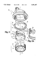
- FIG. 1 is an exploded perspective view of a wheel bearing assembly, rotor and wheel bearing sensor housing in accordance with the present invention.
- FIG. 2 is an exploded perspective view of a stator assembly for use with the wheel bearing speed sensor of the present invention.
- FIG. 3 is a cross-sectional perspective view of the wheel bearing speed sensor of the present invention.
- FIG. 4 is a cross-sectional illustration of the wheel bearing speed sensor of the present invention coupled to a wheel bearing assembly.
- FIGS. 1 and 4 a wheel bearing assembly 10 is shown which, in accordance with the present invention, is normally carried on a non-driven axle of a motor vehicle (not shown). It is to be understood, however, that the concepts of the present invention are equally applicable to bearing assemblies of driven axles.
- Wheel bearing assembly 10 includes a vehicle axis spindle 12 having an outer surface defining an inner race 14.
- Spindle 12 is received within a hub 16 having an inner surface defining an outer race 18.
- Inner race 14 and outer race 18 form a space therebetween for engaging a plurality of rolling bearing members; typically ball bearings 19.
- spindle 12 and inner race 14 are rotatable about an axis 25 while hub 16 and outer race 18 are stationary relative to the spindle 12.
- the foregoing wheel bearing assembly 10 is a conventional wheel bearing assembly and operation thereof is commonly known in the art.
- Rotor 20 should be constructed of a material capable of efficiently conducting magnetic flux and should further be constructed of a material that permits rotor 20 to be easily manufactured.
- rotor 20 is constructed of steel, although the present invention contemplates providing rotor 20 from other magnetically attractible materials as well.
- Rotor 20 has an interior surface 22 which is adapted to mount to the outer surface of the spindle 12 adjacent to the spindle end 13. In its mounted position, rotor 20 rotates with spindle 12 about the rotational axis 25. Rotor 20 further has all outer surface 24 which defines a plurality of equally spaced teeth 26 and slots 28 extending radially therefrom around the periphery of one end 30 of rotor 20. Rotor 20 further extends away from wheel bearing assembly 10 to an opposite rotor end 32. As will be more fully described hereinafter, rotor 20 and a portion of spindle 12 are received within wheel bearing speed sensor housing 90.
- stator assembly 35 is shown in accordance with the present invention. As its central component, stator assembly 35 includes an annular stator 40. Stator 40 should be constructed of a material capable of efficiently conducting magnetic flux and should further be constructed of a material that permits stator 40 to be easily manufactured. Like rotor 20, stator 40 is preferably constructed of steel, although the present invention contemplates providing stator 40 from other magnetically attractible materials as well.
- Stator 40 defines a plurality of teeth 42, equally spaced by a plurality of slots 44, extending axially from the entire periphery of stator end 46 in a direction parallel with the rotational axis 25.
- the opposite end 48 of stator 40 defines a number of recesses 50 therein which terminate at an edge 52.
- stator 40 includes four such recesses, the purpose of which will become readily apparent hereinafter.
- the present invention contemplates providing as few as two recesses 50 and up to an unlimited number of recesses 50.
- Stator 40 further defines an interior surface 56 between the edges 54 of slots 44 and the opposite end 48.
- Stator assembly 35 further includes an annular bobbin member 60 having a plurality of conductor windings 62 around its periphery and contained within channel 64.
- conductor windings 62 are made of copper, although various electrically conducting materials may be used.
- Bobbin member 60 further includes a number of tabs 66 extending radially therefrom. In assembling stator assembly 35, bobbin member 60 is slidably received within stator 40 from the top 48 thereof. As bobbin member 60 is so received, tabs 66 extend into recesses 50 of stator 40 so that the conductor windings 62 are positioned in close proximity to the interior surface 56 of the stator 40.
- insulating tape 63 is wrapped around channel 64 after the conductor windings 62 positioned therein.
- the tabs 66 come into contact with edges 52 of slots 50 so that further movement of bobbin member 60 is thereby restricted.
- the purpose of slots 50 is thus apparent and bobbin member 66 therefore requires a number of tabs 66 equal to, and correspondingly positioned adjacent, recesses 50.
- the bottom surface 68 of bobbin member 60 is positioned radially adjacent slot edges 54.
- the present invention contemplates alternative methods and structure for preventing such axial movement.
- the interior 56 of stator 40 may include a rimmed surface and bobbin member 60 may have a corresponding continuous lip or flange which is received within the rimmed surface to thereby restrict further axial movement.
- the structure shown for so restricting axial movement should therefore not be considered to be limiting, but should be considered to represent one of many possible mechanism contemplated by the present invention to restrict further axial movement of bobbin member 66 toward teeth 42 and slots 44.
- Bobbin member 66 further includes a projection 70 extending axially away from bobbin member 60 in a direction opposite teeth 42 and slots 44 of stator 40.
- Projection 70 defines a pair of slots 72a and 72b for receiving corresponding bifurcated electrical terminals 74a and 74b.
- the ends of conductor winding 62 (not shown) are attached by known methods, such as by soldering, to corresponding terminals 74a and 74b.
- the portions of terminals 74a and 74b extending toward rotation axis 25 include bores 76a and 76b respectively therethrough, the purpose of which will be more fully described hereinafter.
- projection 70 is sized to be received within one of the recesses 50 in stator 40, thereby requiring one less tab 66.
- Projection 70 further defines a pair of flanges 78 (one shown) extending from either side of projection 70 which generally follow the radial contour of bobbin member 60 (and thus the interior 56 of stator 40).
- stator assembly includes a magnet 80 which is adapted to be received within stator 40 adjacent bobbin member 60.
- Magnet 80 has a bottom surface 82 which in the stator assembly 35, is in contact with the upper rim 69 of bobbin member 60.
- Magnet 80 is a bipolar magnet and has a first surface 84 defining one magnetic pole, and a second surface 86 defining an opposite magnetic pole.
- a substantial portion of surface 84 is intended to be in magnetic contact with the inner surface 56 of stator 40 such that surfaces 56 and 84 are magnetically secured.
- This arrangement provides an important aspect of the present invention in that magnet 80, magnetically secured to surface 56 of stator 40, acts to restrict bobbin member 60 from axial movement in a direction opposite teeth 42 and slots 44. From the foregoing, an advantageous feature of the present invention is readily apparent in that stator assembly 35 does not require the use of fixation elements to secure the bobbin member 60 and magnet 80 in their operative positions within stator 40.
- magnet 80 is preferably a flexible strip of magnetic material.
- a flexible strip of rubber is impregnated with magnetic ferrite particles to provide magnet 80.
- rigid or semi-rigid materials may also be used to provide magnet 80 as long as a substantial portion of the magnetic surface 84 maintains magnetic contact with inner surface 56 of stator 40. As will be more fully discussed hereinafter, such magnetic contact contributes to an increased magnetic flux flow efficiency.
- magnet 80 As a flexible strip of magnetic material, it is preferable to configure the ends 87 thereof to correspondingly mate with flanges 78 of bobbin member projection 70. Securing the ends 87 of magnet 80 between corresponding flanges 78 and interior surface 56 of stator 40 keeps the ends 87 from being drawn toward the surface 24 of the rotor 20, under magnetic attraction established between magnetic surface 86 and rotor surface 24, when the rotor is received within stator assembly 35 as most clearly shown in FIG. 3.
- flanges 78 are beveled away from the interior surface 56 of stator 40 and end faces 88 of magnet 80 are correspondingly angled so that they may be secured between beveled flanges 78 and surface 56 within stator assembly 35.
- a non-magnetic housing cup 90 is provided, as previously discussed, for fixedly receiving stator assembly 35 and the rotor 20--spindle 12 combination.
- cup 90 is fixed to stationary hub 16.
- a pair of connector terminals 92a and 92b (FIG. 3) are provided in cup 90 and are received within corresponding bores 76a and 76b of electrical terminals 74a and 74b respectively of bobbin member 60.
- Connector terminals 92a and 92b are electrically attached to terminals 74a and 74b respectively using known electrical attachment techniques such as, for example, soldering.
- Terminals 92a and 92b are further provided external to cup 90 for connection to, for example, an electronic controller or other signal processing device (not shown).
- FIGS. 3 and 4 the assembled wheel bearing speed sensor 100, incorporating sensor assembly 35, rotor 20 and bearing assembly 10, is shown in accordance with a preferred embodiment of the present invention.
- Rotor 20 mounted to the outer surface of the spindle 12 adjacent the spindle end 13, is received within sensor assembly 35 which is, in turn, pressed into non-magnetic housing cup 90.
- rotor teeth 26 and slots 28 are sized identically to a corresponding number of stator teeth 42 and slots 44.
- rotor 20, stator 40, bobbin member 60 and magnet 80 are preferably configured so that gaps therebetween are minimized which results in an increased magnetic flux flow efficiency.
- magnet 80 is magnetically secured to inner surface 56 of stator 40 as previously described.
- bobbin member 60 is in contact with magnet 80 and is further positioned just above the stator (and rotor) teeth 42, also as previously described.
- identically sized rotor teeth 26 (and corresponding slots 28) and stator teeth 42 (and corresponding slots 44) are radially positioned with respect to each other to define a minimum air gap distance therebetween.
- the surface 24 of rotor is radially recessed from rotor teeth 26 so that the same minimum air gap distance exists between the inner surface 65 of bobbin member 60 and rotor surface 24, and between magnet surface 86 and rotor surface 24.
- the vehicle axle spindle 12, and rotor 20 mounted thereto rotate about axis 25.
- the hub 16, stator assembly 35 and stator housing cup 90 remain stationary relative to the rotating spindle 12 and rotor 20.
- the teeth 26 of the rotor 20 are aligned with the identical number of stator teeth 42, a minimum reluctance magnetic flux path is established.
- the magnetic flux travels, in this instance, from the exterior surface 84 of magnet 80 to the interior surface 56 of stator 40, from the interior surface 56 of stator 40 to each of the stator teeth 42, from each of the stator teeth 42 across the minimum distance air gap to each of the correspondingly aligned rotor teeth 26, from each of the rotor teeth 26 to the outer surface 24 of rotor 20, and finally from the outer surface 24 of rotor 24 across the minimal distance air gap to the interior magnet surface 86 to complete the magnetic circuit.
- the rotor teeth 26 and stator teeth 42 become misaligned, thereby increasing the air gap distance therebetween which results in an increased reluctance flux path.
- the radial air gap between the stator 40 and rotor 20 is at a maximum and is defined as the distance between the rotor or stator teeth and corresponding stator or rotor slot. In this position, a maximum magnetic flux reluctance path is established.
Landscapes
- Engineering & Computer Science (AREA)
- Mechanical Engineering (AREA)
- Physics & Mathematics (AREA)
- General Physics & Mathematics (AREA)
- Transportation (AREA)
- Rolling Contact Bearings (AREA)
Abstract
Description
Claims (32)
Priority Applications (6)
| Application Number | Priority Date | Filing Date | Title |
|---|---|---|---|
| US08/383,079 US5491407A (en) | 1995-02-03 | 1995-02-03 | Wheel bearing speed sensor |
| JP8523519A JP3042891B2 (en) | 1995-02-03 | 1995-12-15 | Wheel bearing speed sensor |
| AU46852/96A AU4685296A (en) | 1995-02-03 | 1995-12-15 | Wheel bearing speed sensor |
| DE69523783T DE69523783T2 (en) | 1995-02-03 | 1995-12-15 | SPEED SENSOR FOR WHEEL BEARINGS |
| EP95944486A EP0807257B1 (en) | 1995-02-03 | 1995-12-15 | Wheel bearing speed sensor |
| PCT/US1995/016389 WO1996024068A1 (en) | 1995-02-03 | 1995-12-15 | Wheel bearing speed sensor |
Applications Claiming Priority (1)
| Application Number | Priority Date | Filing Date | Title |
|---|---|---|---|
| US08/383,079 US5491407A (en) | 1995-02-03 | 1995-02-03 | Wheel bearing speed sensor |
Publications (1)
| Publication Number | Publication Date |
|---|---|
| US5491407A true US5491407A (en) | 1996-02-13 |
Family
ID=23511630
Family Applications (1)
| Application Number | Title | Priority Date | Filing Date |
|---|---|---|---|
| US08/383,079 Expired - Fee Related US5491407A (en) | 1995-02-03 | 1995-02-03 | Wheel bearing speed sensor |
Country Status (6)
| Country | Link |
|---|---|
| US (1) | US5491407A (en) |
| EP (1) | EP0807257B1 (en) |
| JP (1) | JP3042891B2 (en) |
| AU (1) | AU4685296A (en) |
| DE (1) | DE69523783T2 (en) |
| WO (1) | WO1996024068A1 (en) |
Cited By (14)
| Publication number | Priority date | Publication date | Assignee | Title |
|---|---|---|---|---|
| US5760576A (en) * | 1994-11-25 | 1998-06-02 | Nsk, Ltd. | Rolling bearing unit with rotational speed sensor having a pair of annular magnets |
| US5825176A (en) * | 1995-06-06 | 1998-10-20 | Ssi Technologies, Inc. | Sensor mounted adjacent an outer member for sensing the rotational speed of a inner member |
| US6549001B1 (en) * | 2001-11-02 | 2003-04-15 | Skf Usa Inc. | Unitized tone ring assembly |
| US20030085697A1 (en) * | 2001-11-02 | 2003-05-08 | David Dobbs | Unitized tone ring assembly |
| US20030201766A1 (en) * | 2002-04-29 | 2003-10-30 | Faetanini Steven E. | Vehicle wheel bearing, wheel-speed sensor mechanism assembly, and wheel speed sensor |
| US20040250631A1 (en) * | 2003-06-10 | 2004-12-16 | Pattok Eric D. | Apparatus for sensing position and/or torque |
| US20050229690A1 (en) * | 2002-05-24 | 2005-10-20 | Masami Kikuchi | Tire temperature sensor, tire heat deterioration detection sensor and tire |
| US20080254901A1 (en) * | 2007-04-16 | 2008-10-16 | Delphi Technologies, Inc. | Magnetic ring systems for attachment to a shaft and methods of making and using |
| US20150272471A1 (en) * | 2012-06-06 | 2015-10-01 | Ellipse Technologies, Inc. | Devices and methods for detection of slippage of magnetic coupling in implantable medical devices |
| CN108463652A (en) * | 2016-03-24 | 2018-08-28 | 雷诺股份公司 | Differential ring gear equipped with a target for measuring its rotational speed and arrangement in a gearbox |
| EP3460487A3 (en) * | 2017-09-22 | 2019-06-19 | Goodrich Corporation | Wheel rotational direction sensor |
| US20200122698A1 (en) * | 2018-10-23 | 2020-04-23 | Steven R. Bollinger | Wheel sensors within vehicular brake assemblies |
| US11066051B2 (en) * | 2018-10-23 | 2021-07-20 | Dexter Axle Company | Wheel sensors within vehicular brake assemblies |
| CN116068217A (en) * | 2022-12-30 | 2023-05-05 | 北京航辰机载智能系统科技有限公司 | a wheel speed sensor |
Families Citing this family (1)
| Publication number | Priority date | Publication date | Assignee | Title |
|---|---|---|---|---|
| GB2351950B (en) * | 1999-06-24 | 2002-11-27 | Nsk Rhp Europe Technology Co Ltd | A hub component for vehicle wheels |
Citations (19)
| Publication number | Priority date | Publication date | Assignee | Title |
|---|---|---|---|---|
| US3500091A (en) * | 1968-04-18 | 1970-03-10 | Kelsey Hayes Co | Electrical rotational speed sensing device |
| US3551712A (en) * | 1968-07-25 | 1970-12-29 | Kelsey Hayes Co | Sensor with flexible coupling |
| US3739211A (en) * | 1971-10-15 | 1973-06-12 | Amper Corp | Magnetic tachometer |
| US3960248A (en) * | 1975-07-16 | 1976-06-01 | Kelsey-Hayes Company | Speed sensing device |
| US4027753A (en) * | 1976-04-15 | 1977-06-07 | The B.F. Goodrich Company | In-axle vehicle wheel speed sensing device |
| US4904936A (en) * | 1986-03-03 | 1990-02-27 | Emhart Industries, Inc. | Automotive wheel speed sensor including ferromagnetic flux carrying cup closing an opening in the wheel bearing housing |
| US4954775A (en) * | 1986-03-03 | 1990-09-04 | Emhart Industries Inc. | Automotive wheel speed sensor assembly with multipole rotor mounted on wheel bearing spindle |
| US4968933A (en) * | 1986-03-03 | 1990-11-06 | Emhart Industries, Inc. | Automotive wheel speed sensor assembly with stator pole piece carried within aperture of field coil |
| US4970462A (en) * | 1986-03-03 | 1990-11-13 | Emhart Industries, Inc. | Automotive wheel speed sensor assembly with rotor and stator, one of which has only a few poles |
| US5023547A (en) * | 1989-11-08 | 1991-06-11 | General Motors Corporation | Variable reluctance rotation sensor with changing flux linkages and including a pair of oppositely poled magnets |
| US5111098A (en) * | 1988-08-24 | 1992-05-05 | Rockwell International Corporation | Unitary rotational speed sensor |
| US5140261A (en) * | 1989-06-02 | 1992-08-18 | Koyo Seiko Co., Ltd. | Bearing apparatus for a driven shaft of an automobile having a rotational speed detector |
| US5200697A (en) * | 1991-11-27 | 1993-04-06 | Ntn Corporation | Hub and bearing assembly with integrated rotation sensor including a tone ring and annular transducer |
| US5227719A (en) * | 1990-09-07 | 1993-07-13 | Eaton Corporation | Drive axle in-axle annular speed sensor |
| US5281911A (en) * | 1991-11-08 | 1994-01-25 | Eaton Corporation | Vehicle wheel speed sensor employing a locating plate |
| US5291130A (en) * | 1993-01-25 | 1994-03-01 | Eaton Corporation | Vehicle wheel speed sensor employing an adaptable rotor cap |
| US5296805A (en) * | 1992-08-17 | 1994-03-22 | General Motors Corporation | Serviceable wheel speed sensor with magnet assisted retention |
| US5332964A (en) * | 1991-10-16 | 1994-07-26 | Nsk Ltd. | Rolling bearing unit with permanent magnet, coil and back yoke for sensing rotational speed of automotive wheel |
| US5336995A (en) * | 1990-09-07 | 1994-08-09 | Eaton Corporati | Annular speed sensor with strain relief |
Family Cites Families (1)
| Publication number | Priority date | Publication date | Assignee | Title |
|---|---|---|---|---|
| JP3189624B2 (en) * | 1994-08-11 | 2001-07-16 | 日本精工株式会社 | Rolling bearing unit with rotation speed detector |
-
1995
- 1995-02-03 US US08/383,079 patent/US5491407A/en not_active Expired - Fee Related
- 1995-12-15 DE DE69523783T patent/DE69523783T2/en not_active Expired - Fee Related
- 1995-12-15 AU AU46852/96A patent/AU4685296A/en not_active Abandoned
- 1995-12-15 EP EP95944486A patent/EP0807257B1/en not_active Expired - Lifetime
- 1995-12-15 JP JP8523519A patent/JP3042891B2/en not_active Expired - Fee Related
- 1995-12-15 WO PCT/US1995/016389 patent/WO1996024068A1/en not_active Ceased
Patent Citations (20)
| Publication number | Priority date | Publication date | Assignee | Title |
|---|---|---|---|---|
| US3500091A (en) * | 1968-04-18 | 1970-03-10 | Kelsey Hayes Co | Electrical rotational speed sensing device |
| US3551712A (en) * | 1968-07-25 | 1970-12-29 | Kelsey Hayes Co | Sensor with flexible coupling |
| US3739211A (en) * | 1971-10-15 | 1973-06-12 | Amper Corp | Magnetic tachometer |
| US3960248A (en) * | 1975-07-16 | 1976-06-01 | Kelsey-Hayes Company | Speed sensing device |
| US4027753A (en) * | 1976-04-15 | 1977-06-07 | The B.F. Goodrich Company | In-axle vehicle wheel speed sensing device |
| US4904936A (en) * | 1986-03-03 | 1990-02-27 | Emhart Industries, Inc. | Automotive wheel speed sensor including ferromagnetic flux carrying cup closing an opening in the wheel bearing housing |
| US4954775A (en) * | 1986-03-03 | 1990-09-04 | Emhart Industries Inc. | Automotive wheel speed sensor assembly with multipole rotor mounted on wheel bearing spindle |
| US4968933A (en) * | 1986-03-03 | 1990-11-06 | Emhart Industries, Inc. | Automotive wheel speed sensor assembly with stator pole piece carried within aperture of field coil |
| US4970462A (en) * | 1986-03-03 | 1990-11-13 | Emhart Industries, Inc. | Automotive wheel speed sensor assembly with rotor and stator, one of which has only a few poles |
| US5111098A (en) * | 1988-08-24 | 1992-05-05 | Rockwell International Corporation | Unitary rotational speed sensor |
| US5140261A (en) * | 1989-06-02 | 1992-08-18 | Koyo Seiko Co., Ltd. | Bearing apparatus for a driven shaft of an automobile having a rotational speed detector |
| US5023547A (en) * | 1989-11-08 | 1991-06-11 | General Motors Corporation | Variable reluctance rotation sensor with changing flux linkages and including a pair of oppositely poled magnets |
| US5227719A (en) * | 1990-09-07 | 1993-07-13 | Eaton Corporation | Drive axle in-axle annular speed sensor |
| US5336995A (en) * | 1990-09-07 | 1994-08-09 | Eaton Corporati | Annular speed sensor with strain relief |
| US5332964A (en) * | 1991-10-16 | 1994-07-26 | Nsk Ltd. | Rolling bearing unit with permanent magnet, coil and back yoke for sensing rotational speed of automotive wheel |
| US5281911A (en) * | 1991-11-08 | 1994-01-25 | Eaton Corporation | Vehicle wheel speed sensor employing a locating plate |
| US5200697A (en) * | 1991-11-27 | 1993-04-06 | Ntn Corporation | Hub and bearing assembly with integrated rotation sensor including a tone ring and annular transducer |
| US5200697B1 (en) * | 1991-11-27 | 1996-06-18 | Ntn Toyo Bearing Co Ltd | Hub and bearing assembly with integrated rotation sensor including a tone ring and annular transducer |
| US5296805A (en) * | 1992-08-17 | 1994-03-22 | General Motors Corporation | Serviceable wheel speed sensor with magnet assisted retention |
| US5291130A (en) * | 1993-01-25 | 1994-03-01 | Eaton Corporation | Vehicle wheel speed sensor employing an adaptable rotor cap |
Cited By (26)
| Publication number | Priority date | Publication date | Assignee | Title |
|---|---|---|---|---|
| US5760576A (en) * | 1994-11-25 | 1998-06-02 | Nsk, Ltd. | Rolling bearing unit with rotational speed sensor having a pair of annular magnets |
| US5825176A (en) * | 1995-06-06 | 1998-10-20 | Ssi Technologies, Inc. | Sensor mounted adjacent an outer member for sensing the rotational speed of a inner member |
| US6549001B1 (en) * | 2001-11-02 | 2003-04-15 | Skf Usa Inc. | Unitized tone ring assembly |
| US20030085697A1 (en) * | 2001-11-02 | 2003-05-08 | David Dobbs | Unitized tone ring assembly |
| WO2003040730A1 (en) * | 2001-11-02 | 2003-05-15 | Skf Usa Inc. | Unitized tone ring assembly |
| US6664780B2 (en) * | 2001-11-02 | 2003-12-16 | Skf Usa Inc. | Unitized tone ring assembly |
| US20030201766A1 (en) * | 2002-04-29 | 2003-10-30 | Faetanini Steven E. | Vehicle wheel bearing, wheel-speed sensor mechanism assembly, and wheel speed sensor |
| US6774622B2 (en) * | 2002-04-29 | 2004-08-10 | Delphi Technologies, Inc. | Vehicle wheel bearing, wheel-speed sensor mechanism assembly, and wheel speed sensor |
| US20050229690A1 (en) * | 2002-05-24 | 2005-10-20 | Masami Kikuchi | Tire temperature sensor, tire heat deterioration detection sensor and tire |
| US7021160B2 (en) * | 2003-06-10 | 2006-04-04 | Delphi Technologies, Inc. | Apparatus for sensing position and/or torque |
| US20050172727A1 (en) * | 2003-06-10 | 2005-08-11 | Delphi Technologies, Inc. | Apparatus for sensing position and/or torque |
| US20040250631A1 (en) * | 2003-06-10 | 2004-12-16 | Pattok Eric D. | Apparatus for sensing position and/or torque |
| US7188533B2 (en) | 2003-06-10 | 2007-03-13 | Delphi Technologies, Inc. | Apparatus for sensing position and/or torque |
| WO2005083380A1 (en) * | 2004-02-06 | 2005-09-09 | Delphi Technologies, Inc. | Apparatus for sensing position and/or torque |
| US20080254901A1 (en) * | 2007-04-16 | 2008-10-16 | Delphi Technologies, Inc. | Magnetic ring systems for attachment to a shaft and methods of making and using |
| US8083431B2 (en) * | 2007-04-16 | 2011-12-27 | Nexteer (Beijing) Technology Co., Ltd. | Magnetic ring systems for attachment to a shaft and methods of making and using |
| US20150272471A1 (en) * | 2012-06-06 | 2015-10-01 | Ellipse Technologies, Inc. | Devices and methods for detection of slippage of magnetic coupling in implantable medical devices |
| US9730612B2 (en) * | 2012-06-06 | 2017-08-15 | Nuvasive Specialized Orthopedics, Inc. | Devices and methods for detection of slippage of magnetic coupling in implantable medical devices |
| CN108463652A (en) * | 2016-03-24 | 2018-08-28 | 雷诺股份公司 | Differential ring gear equipped with a target for measuring its rotational speed and arrangement in a gearbox |
| EP3460487A3 (en) * | 2017-09-22 | 2019-06-19 | Goodrich Corporation | Wheel rotational direction sensor |
| US10584965B2 (en) | 2017-09-22 | 2020-03-10 | Goodrich Corporation | Wheel speed and direction sensor |
| EP4109109A1 (en) | 2017-09-22 | 2022-12-28 | Goodrich Corporation | Wheel speed and direction sensor |
| US20200122698A1 (en) * | 2018-10-23 | 2020-04-23 | Steven R. Bollinger | Wheel sensors within vehicular brake assemblies |
| US10889275B2 (en) * | 2018-10-23 | 2021-01-12 | Dexter Axle Company | Wheel sensors within vehicular brake assemblies |
| US11066051B2 (en) * | 2018-10-23 | 2021-07-20 | Dexter Axle Company | Wheel sensors within vehicular brake assemblies |
| CN116068217A (en) * | 2022-12-30 | 2023-05-05 | 北京航辰机载智能系统科技有限公司 | a wheel speed sensor |
Also Published As
| Publication number | Publication date |
|---|---|
| JPH10509519A (en) | 1998-09-14 |
| EP0807257A1 (en) | 1997-11-19 |
| AU4685296A (en) | 1996-08-21 |
| JP3042891B2 (en) | 2000-05-22 |
| DE69523783D1 (en) | 2001-12-13 |
| DE69523783T2 (en) | 2002-08-08 |
| EP0807257B1 (en) | 2001-11-07 |
| WO1996024068A1 (en) | 1996-08-08 |
| EP0807257A4 (en) | 1998-06-03 |
Similar Documents
| Publication | Publication Date | Title |
|---|---|---|
| US5491407A (en) | Wheel bearing speed sensor | |
| JP3009869U (en) | Encoder element for rolling bearing with information sensor assembly and bearing having the same | |
| CA2114064C (en) | Vehicle wheel speed sensor employing an adaptable rotor cap | |
| US5850141A (en) | Annular speed sensor with a tone ring having both axial and radial magnetic fields | |
| KR960005343B1 (en) | Toroidal speed sensor | |
| JPH0649826U (en) | Bearing seal device and bearing device | |
| GB1472789A (en) | Wheel speed sensor | |
| US5504424A (en) | Variable reluctance sensor utilizing a magnetic bobbin | |
| US5583431A (en) | Hub unit with rotation speed sensor | |
| US5332964A (en) | Rolling bearing unit with permanent magnet, coil and back yoke for sensing rotational speed of automotive wheel | |
| JP3862302B2 (en) | Rolling bearing unit with rotational speed detector | |
| JP2002372548A (en) | Bearing device for wheel | |
| US4288746A (en) | Measuring sensor | |
| US4970462A (en) | Automotive wheel speed sensor assembly with rotor and stator, one of which has only a few poles | |
| GB2199143A (en) | A rotary member for a device for detecting rotational speed or angular velocity | |
| US5574361A (en) | Switched reluctance angular velocity sensor | |
| US6051969A (en) | Sensor rotor made from ring pieces having outer and inner edges with identical radiuses of curvature | |
| US4954775A (en) | Automotive wheel speed sensor assembly with multipole rotor mounted on wheel bearing spindle | |
| JPS6123806Y2 (en) | ||
| US5777466A (en) | Annular speed sensor for a bearing assembly with a set of teeth being bent toward other set of teeth | |
| JP3653885B2 (en) | Magnetizer for encoder for rotational speed detector | |
| US4968933A (en) | Automotive wheel speed sensor assembly with stator pole piece carried within aperture of field coil | |
| JP3632338B2 (en) | Rolling bearing unit with rotational speed detector | |
| JPH04212634A (en) | Rotary type speed sensor | |
| JPS6026546Y2 (en) | Flat motor with speed detector |
Legal Events
| Date | Code | Title | Description |
|---|---|---|---|
| AS | Assignment |
Owner name: KEARNEY-NATIONAL, INC., NEW YORK Free format text: ASSIGNMENT OF ASSIGNORS INTEREST;ASSIGNORS:MAXSON, WILLIAM R.;HEINIGER, JERRY D.;RUSTMAN, JAMES D.;REEL/FRAME:007364/0910 Effective date: 19950202 |
|
| CC | Certificate of correction | ||
| REFU | Refund |
Free format text: REFUND - SURCHARGE FOR LATE PAYMENT, LARGE ENTITY (ORIGINAL EVENT CODE: R186); ENTITY STATUS OF PATENT OWNER: LARGE ENTITY Free format text: REFUND - PAYMENT OF MAINTENANCE FEE, 4TH YEAR, LARGE ENTITY (ORIGINAL EVENT CODE: R183); ENTITY STATUS OF PATENT OWNER: LARGE ENTITY |
|
| FPAY | Fee payment |
Year of fee payment: 4 |
|
| AS | Assignment |
Owner name: WABASH TECHNOLOGIES, INC., INDIANA Free format text: ASSIGNMENT OF ASSIGNORS INTEREST;ASSIGNOR:KEARNEY-NATIONAL, INC.;REEL/FRAME:012463/0032 Effective date: 20011018 |
|
| AS | Assignment |
Owner name: BANK OF AMERICA, N.A., AS SENIOR CREDITOR AGENT, N Free format text: NOTICE OF GRANT OF SECURITY INTEREST;ASSIGNOR:WABASH TECHNOLOGIES, INC.;REEL/FRAME:013101/0955 Effective date: 20020529 |
|
| AS | Assignment |
Owner name: BANK OF AMERICA, N.A. AS SENIOR CREDITOR AGENT, NO Free format text: SECURITY INTEREST;ASSIGNOR:WABASH MAGNETICS, LLC;REEL/FRAME:014210/0955 Effective date: 20020529 |
|
| REMI | Maintenance fee reminder mailed | ||
| LAPS | Lapse for failure to pay maintenance fees | ||
| FP | Lapsed due to failure to pay maintenance fee |
Effective date: 20040213 |
|
| AS | Assignment |
Owner name: WABASH MAGNETICS, LLC, INDIANA Free format text: TERMINATION OF SECURITY INTERESTS IN PATENTS;ASSIGNOR:BANK OF AMERICA, N.A. AS SENIOR CREDITOR AGENT;REEL/FRAME:020186/0142 Effective date: 20071128 Owner name: WABASH TECHNOLOGIES, INC., INDIANA Free format text: TERMINATION OF SECURITY INTEREST IN PATENTS;ASSIGNOR:BANK OF AMERICA, N.A. AS SENIOR CREDITOR AGENT;REEL/FRAME:020186/0093 Effective date: 20071128 |
|
| STCH | Information on status: patent discontinuation |
Free format text: PATENT EXPIRED DUE TO NONPAYMENT OF MAINTENANCE FEES UNDER 37 CFR 1.362 |