EP3460465A1 - Jig for ultrasonic fatigue testing machine - Google Patents
Jig for ultrasonic fatigue testing machine Download PDFInfo
- Publication number
- EP3460465A1 EP3460465A1 EP18192109.9A EP18192109A EP3460465A1 EP 3460465 A1 EP3460465 A1 EP 3460465A1 EP 18192109 A EP18192109 A EP 18192109A EP 3460465 A1 EP3460465 A1 EP 3460465A1
- Authority
- EP
- European Patent Office
- Prior art keywords
- test piece
- jig
- testing machine
- screw
- fatigue testing
- Prior art date
- Legal status (The legal status is an assumption and is not a legal conclusion. Google has not performed a legal analysis and makes no representation as to the accuracy of the status listed.)
- Withdrawn
Links
- 238000009661 fatigue test Methods 0.000 title claims description 63
- 238000012360 testing method Methods 0.000 claims abstract description 186
- 238000003825 pressing Methods 0.000 claims description 14
- 230000005484 gravity Effects 0.000 abstract description 9
- 238000010586 diagram Methods 0.000 description 20
- 239000000463 material Substances 0.000 description 13
- 238000006073 displacement reaction Methods 0.000 description 7
- 238000004519 manufacturing process Methods 0.000 description 7
- 238000000034 method Methods 0.000 description 6
- 125000006850 spacer group Chemical group 0.000 description 5
- 229910000831 Steel Inorganic materials 0.000 description 4
- 239000010959 steel Substances 0.000 description 4
- 238000005219 brazing Methods 0.000 description 3
- 238000004364 calculation method Methods 0.000 description 3
- 238000002788 crimping Methods 0.000 description 3
- 238000003466 welding Methods 0.000 description 3
- 230000003321 amplification Effects 0.000 description 2
- 239000004918 carbon fiber reinforced polymer Substances 0.000 description 2
- 239000002131 composite material Substances 0.000 description 2
- 238000003199 nucleic acid amplification method Methods 0.000 description 2
- 238000004088 simulation Methods 0.000 description 2
- 229910052782 aluminium Inorganic materials 0.000 description 1
- XAGFODPZIPBFFR-UHFFFAOYSA-N aluminium Chemical compound [Al] XAGFODPZIPBFFR-UHFFFAOYSA-N 0.000 description 1
- 230000005540 biological transmission Effects 0.000 description 1
- 230000007423 decrease Effects 0.000 description 1
- 230000000694 effects Effects 0.000 description 1
- 239000000835 fiber Substances 0.000 description 1
- 238000010030 laminating Methods 0.000 description 1
- 229910052751 metal Inorganic materials 0.000 description 1
- 239000002184 metal Substances 0.000 description 1
- 239000007769 metal material Substances 0.000 description 1
- 230000000149 penetrating effect Effects 0.000 description 1
- 238000010079 rubber tapping Methods 0.000 description 1
- 230000003068 static effect Effects 0.000 description 1
- 238000009864 tensile test Methods 0.000 description 1
Images




Classifications
-
- G—PHYSICS
- G01—MEASURING; TESTING
- G01N—INVESTIGATING OR ANALYSING MATERIALS BY DETERMINING THEIR CHEMICAL OR PHYSICAL PROPERTIES
- G01N29/00—Investigating or analysing materials by the use of ultrasonic, sonic or infrasonic waves; Visualisation of the interior of objects by transmitting ultrasonic or sonic waves through the object
- G01N29/22—Details, e.g. general constructional or apparatus details
- G01N29/221—Arrangements for directing or focusing the acoustical waves
-
- G—PHYSICS
- G01—MEASURING; TESTING
- G01N—INVESTIGATING OR ANALYSING MATERIALS BY DETERMINING THEIR CHEMICAL OR PHYSICAL PROPERTIES
- G01N3/00—Investigating strength properties of solid materials by application of mechanical stress
- G01N3/02—Details
- G01N3/04—Chucks
-
- G—PHYSICS
- G01—MEASURING; TESTING
- G01M—TESTING STATIC OR DYNAMIC BALANCE OF MACHINES OR STRUCTURES; TESTING OF STRUCTURES OR APPARATUS, NOT OTHERWISE PROVIDED FOR
- G01M5/00—Investigating the elasticity of structures, e.g. deflection of bridges or air-craft wings
- G01M5/0066—Investigating the elasticity of structures, e.g. deflection of bridges or air-craft wings by exciting or detecting vibration or acceleration
-
- G—PHYSICS
- G01—MEASURING; TESTING
- G01M—TESTING STATIC OR DYNAMIC BALANCE OF MACHINES OR STRUCTURES; TESTING OF STRUCTURES OR APPARATUS, NOT OTHERWISE PROVIDED FOR
- G01M5/00—Investigating the elasticity of structures, e.g. deflection of bridges or air-craft wings
- G01M5/0091—Investigating the elasticity of structures, e.g. deflection of bridges or air-craft wings by using electromagnetic excitation or detection
-
- G—PHYSICS
- G01—MEASURING; TESTING
- G01M—TESTING STATIC OR DYNAMIC BALANCE OF MACHINES OR STRUCTURES; TESTING OF STRUCTURES OR APPARATUS, NOT OTHERWISE PROVIDED FOR
- G01M7/00—Vibration-testing of structures; Shock-testing of structures
- G01M7/02—Vibration-testing by means of a shake table
- G01M7/022—Vibration control arrangements, e.g. for generating random vibrations
-
- G—PHYSICS
- G01—MEASURING; TESTING
- G01M—TESTING STATIC OR DYNAMIC BALANCE OF MACHINES OR STRUCTURES; TESTING OF STRUCTURES OR APPARATUS, NOT OTHERWISE PROVIDED FOR
- G01M7/00—Vibration-testing of structures; Shock-testing of structures
- G01M7/02—Vibration-testing by means of a shake table
- G01M7/027—Specimen mounting arrangements, e.g. table head adapters
-
- G—PHYSICS
- G01—MEASURING; TESTING
- G01N—INVESTIGATING OR ANALYSING MATERIALS BY DETERMINING THEIR CHEMICAL OR PHYSICAL PROPERTIES
- G01N29/00—Investigating or analysing materials by the use of ultrasonic, sonic or infrasonic waves; Visualisation of the interior of objects by transmitting ultrasonic or sonic waves through the object
- G01N29/22—Details, e.g. general constructional or apparatus details
-
- G—PHYSICS
- G01—MEASURING; TESTING
- G01N—INVESTIGATING OR ANALYSING MATERIALS BY DETERMINING THEIR CHEMICAL OR PHYSICAL PROPERTIES
- G01N29/00—Investigating or analysing materials by the use of ultrasonic, sonic or infrasonic waves; Visualisation of the interior of objects by transmitting ultrasonic or sonic waves through the object
- G01N29/22—Details, e.g. general constructional or apparatus details
- G01N29/223—Supports, positioning or alignment in fixed situation
-
- G—PHYSICS
- G01—MEASURING; TESTING
- G01N—INVESTIGATING OR ANALYSING MATERIALS BY DETERMINING THEIR CHEMICAL OR PHYSICAL PROPERTIES
- G01N2203/00—Investigating strength properties of solid materials by application of mechanical stress
- G01N2203/003—Generation of the force
- G01N2203/0055—Generation of the force using mechanical waves, e.g. acoustic
-
- G—PHYSICS
- G01—MEASURING; TESTING
- G01N—INVESTIGATING OR ANALYSING MATERIALS BY DETERMINING THEIR CHEMICAL OR PHYSICAL PROPERTIES
- G01N2203/00—Investigating strength properties of solid materials by application of mechanical stress
- G01N2203/0058—Kind of property studied
- G01N2203/0069—Fatigue, creep, strain-stress relations or elastic constants
- G01N2203/0073—Fatigue
-
- G—PHYSICS
- G01—MEASURING; TESTING
- G01N—INVESTIGATING OR ANALYSING MATERIALS BY DETERMINING THEIR CHEMICAL OR PHYSICAL PROPERTIES
- G01N2203/00—Investigating strength properties of solid materials by application of mechanical stress
- G01N2203/02—Details not specific for a particular testing method
- G01N2203/04—Chucks, fixtures, jaws, holders or anvils
- G01N2203/0423—Chucks, fixtures, jaws, holders or anvils using screws
-
- G—PHYSICS
- G01—MEASURING; TESTING
- G01N—INVESTIGATING OR ANALYSING MATERIALS BY DETERMINING THEIR CHEMICAL OR PHYSICAL PROPERTIES
- G01N2291/00—Indexing codes associated with group G01N29/00
- G01N2291/02—Indexing codes associated with the analysed material
- G01N2291/023—Solids
- G01N2291/0231—Composite or layered materials
-
- G—PHYSICS
- G01—MEASURING; TESTING
- G01N—INVESTIGATING OR ANALYSING MATERIALS BY DETERMINING THEIR CHEMICAL OR PHYSICAL PROPERTIES
- G01N2291/00—Indexing codes associated with group G01N29/00
- G01N2291/02—Indexing codes associated with the analysed material
- G01N2291/025—Change of phase or condition
- G01N2291/0258—Structural degradation, e.g. fatigue of composites, ageing of oils
Definitions
- the present invention relates to a jig for an ultrasonic fatigue testing machine attached to a test piece when performing a fatigue test by resonating the test piece using an ultrasonic wave.
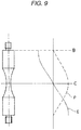
- Fig. 9 is an explanatory diagram illustrating a relationship of a shape of an annular test piece of the related art with respect to stress curve and an amplitude curve.
- an annular test piece is illustrated on the left side of the drawing and an axial stress curve P indicated by a dashed line and a displacement curve E indicated by a solid line are illustrated on the right side of the drawing.
- a test piece for an ultrasonic fatigue test needs to have the same resonance frequency as the ultrasonic vibration generated from the ultrasonic transducer.
- a shape of the test piece is designed such that stress amplification becomes zero at a test piece attachment position B in the horn (becomes an antinode of a displacement vibration) and stress amplification becomes maximal at a center position C of the test piece (becomes a node of the displacement vibration).
- a male screw corresponding to a female screw formed at a front end of the horn is integrally formed with a body of the test piece at the time of manufacturing the test piece by processing the material (see Fig. 9 of Patent Literature 1).
- the ultrasonic fatigue testing machine is designed for a standard annular test piece. Accordingly, even when a plate-shaped test piece is manufactured for an ultrasonic fatigue test, a male screw having a screw diameter corresponding to the female screw of the horn needs to be formed similarly to the annular test piece.
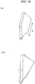
- Fig. 10 is a diagram illustrating a resonance simulation of a plate-shaped test piece model. Additionally, Fig. 10 illustrates a 1/2 model in which the plate-shaped test piece designed so that stress at the center portion during resonance becomes the same as that of the annular test piece is cut at the center portion thereof.
- Fig. 10(a) illustrates a state before the resonance occurs.
- Fig. 10(b) illustrates a state where a maximal sinusoidal stress waveform which can be realized by a general ultrasonic fatigue testing machine is applied to the test piece, where the test piece before the resonance occurs is indicated by a dashed line and the test piece having a lateral vibration during resonance is indicated by a solid line.
- the plate-shaped test piece of Fig. 10 is designed so that the stress at the center portion is the same as that of the annular test piece by a configuration in which the width dimensions at both ends are larger than the diameter of the center portion.
- the test piece is vibrated longitudinally in parallel to the wave traveling direction (a direction of an arrow A of Fig. 10(a) ).
- a lateral vibration occurs at frequencies close to longitudinal vibration as indicated by a solid line in Fig. 10 (b) and thus a normal test is hindered. In this way, there is a case where the plate-shaped test piece corresponding to high stress is not easily manufactured.
- the invention has been made to solve the above-described problems and an object of the invention is to provide a jig for an ultrasonic fatigue testing machine capable of facilitating a design of a test piece formed of various materials and performing a fatigue test in which high stress is repeatedly applied to a test piece.
- a jig for an ultrasonic fatigue testing machine used in a fatigue test in which a vibration generated from an ultrasonic transducer is amplified by a horn and a test piece connected to a front end of the horn is resonated, including: a main body portion; and a grip portion holding an end of the test piece, in which the jig is attached to both ends of the test piece to adjust the mass of both ends of the test piece.
- the jig for the ultrasonic fatigue testing machine of claim 1 in which an end of the main body portion opposite to the grip portion is provided with a screw portion to be connected to the horn.
- the jig for the ultrasonic fatigue testing machine of claim 1 in which when an end of the main body portion is connected to the horn, an adjustment plate is inserted between the main body portion and the horn, and when the end of the main body portion serves as a free end, the adjustment plate is attached to the free end to adjust the mass of both ends of the test piece.
- the jig for the ultrasonic fatigue testing machine of claim 1 in which the grip portion includes a pressing force generation member that sandwiches the end of the test piece by a pressing force using a screw when holding the end of the test piece.
- the jig for the ultrasonic fatigue testing machine of claim 4 in which the mass of both ends of the test piece is adjusted by changing the weight of the pressing force generation member.
- the jig for the ultrasonic fatigue testing machine is attached to both ends of the test piece, it is possible to increase the mass near the end of the test piece. Accordingly, since it is possible to increase the mass near the end of the test piece in relation to the center portion of the test piece without increasing the mass of the end of the test piece itself, it is possible to repeatedly apply high stress as a target value to the center portion of the test piece. Thus, it is possible to perform a fatigue test with high stress of 1000 MPa for the test piece even in a current device without increasing the capacity of the ultrasonic fatigue testing machine designed for the annular test piece.
- the jig for the ultrasonic fatigue testing machine is attached to both ends of the test piece, it is not necessary to provide the screw portion to be connected to the horn of the ultrasonic fatigue testing machine at the test piece itself when manufacturing the test piece and it is possible to perform an ultrasonic fatigue test for a material which is not easily subjected to threading.
- the jig for the ultrasonic fatigue testing machine is prepared as a pair of jigs each having a different weight, even when the accuracy of the desired resonance frequency is not obtained in the test piece manufactured according to a length obtained by a calculation, it is possible to easily adjust the resonance frequency by replacing the jig for the ultrasonic fatigue testing machine attached to the test piece with another jig having a different weight since the resonance frequency ⁇ is ⁇ (spring constant/mass) in a simple spring-mass system. For this reason, since there is no need to determine an optimal test piece length by measuring each resonance frequency after manufacturing test pieces each having a different length as in the related art, it is possible to easily manufacture the test piece.
- the adjustment plate since the mass of both ends of the test piece is adjusted by the adjustment plate, it is possible to easily and finely adjust the resonance frequency corresponding to target stress applied to the center portion of the test piece by adjusting the number of the adjustment plates or the thickness thereof.
- the weight of the pressing force generation member in response to the target stress applied to the center portion of the test piece, it is possible to more easily change the weight of the jig for the ultrasonic fatigue testing machine and thus to finely adjust the resonance frequency of the test piece.
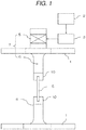
- Fig. 1 is an outline diagram of an ultrasonic fatigue testing machine which performs a fatigue test by attaching a jig 10 for the ultrasonic fatigue testing machine according to the invention thereto.
- the ultrasonic fatigue testing machine is used to perform a fatigue test by resonating a test piece S using ultrasonic waves and includes a vibration portion 7 which includes an ultrasonic transducer 5 vibrated by a signal generated from an oscillator 3 and a horn 6 amplifying a vibration and transmitting the vibration to the test piece S and a frame 1 which is attached to the vibration portion 7.
- the oscillator 3 generates the signal based on a test frequency set by a control unit 2.
- the arrangement of the vibration portion 13 and the test piece S illustrated in Fig. 1 is set to perform a fatigue test in which a longitudinal vibration is applied to the test piece S.
- the test piece S is a plate-shaped test piece and both ends thereof are sandwiched by a pair of jigs 10 for the ultrasonic fatigue testing machine (hereinafter, the jig 10 for the ultrasonic fatigue testing machine will be referred to as the "jig 10" if necessary in the specification).
- the pair of jigs 10 has the same mass and the mass is adjusted in consideration of the test piece shape so that the stress at the center portion of the test piece S becomes a desired value (target stress) within the ability range of the device. That is, the jig 10 serves as a weight adjustment tool for adjusting the resonance frequency and the stress of the test piece S. In order to adjust the weight, the length or width of the jig 10 may be adjusted.
- the upper and lower jigs 10 are attached to both ends of the test piece S so that the center of gravity of the upper jig 10 and the center of gravity of the lower jig 10 are located on a vertical line passing through the center portion of the test piece S.
- the upper jig 10 is connected to the horn 6 by the screw-connection.
- the lower jig 10 is connected to the horn 6 fixed to the frame 1 by the screw-connection.
- the lower jig 10 is also connected to the horn 6 resonated at the same cycle in order to apply average stress to the test piece S. Additionally, the lower jig 10 may be a free end according to the purpose of the test. Further, in the example of Fig. 1 , a longitudinal vibration is applied to the test piece S from the upper side of the test piece S, but when a vibration is applied to the test piece S from the upper and lower sides of the frame 1, the horn 6 connected to the lower jig 10 is also connected to the ultrasonic transducer 5 and the oscillator 3.
- Fig. 2 is an outline diagram of the jig 10 for the ultrasonic fatigue testing machine according to the invention.
- the jig 10 includes a main body portion 11 and a pair of grip portions 12 which sandwiches the end of the test piece S.
- An end (an end surface) of the main body portion 11 of the jig 10 at a connection side to the horn 6 and a side opposite to the grip portion 12 is provided with a screw portion 16 which is connected to the front end of the horn 6 by the screw-connection.
- the end of the test piece S is inserted between the pair of grip portions 12 and the test piece S and the jig 10 are integrally held by shrink fitting, crimping, or fixing such as welding, brazing, or adhering.
- the pair of jigs 10 is attached to the test piece S so that the centers of gravity of the pair of jigs 10 are aligned to the line passing through the center portion of the test piece S.
- Fig. 3 is an outline diagram illustrating a weight adjustment of the jig 10 for the ultrasonic fatigue testing machine.
- Fig. 3(a) illustrates the weight adjustment of the jig 10 connected to the horn 6 by the screw-connection and
- Fig. 3(b) illustrates the weight adjustment when the lower jig 10 is a free end.
- the pair of jigs 10 is prepared to have the same mass according to the size of the test piece S. Meanwhile, in the prepared jig 10, there is a case where the weight is insufficient for the stress at the center portion of the test piece S to become a desired value (target stress). In such a case, as illustrated in Fig. 3 , the weight of the pair of jigs 10 is adjusted.
- the weight of the jig 10 is adjusted.
- the substantial mass of both ends of the test piece S can be set to be sufficiently larger than that of the center portion so that stress at the center portion of the test piece S becomes a target value.
- a plurality of adjustment plates 13a and 13b each having a different thickness are provided.
- the adjustment plates 13a and 13b are provided with holes through which the screw portion 16 passes.
- the adjustment plates 13a and 13b each having a different thickness are selected to have a target weight and are inserted between the front end of the horn 6 and the jig 10 so that the weight of both ends of the test piece S is adjusted. Additionally, when the lower jig 10 is not connected to the horn 6 and is used as a free end, an end surface of the jig 10 is provided with a male screw and the adjustment plates 14a and 14b each having a different thickness are fixed by a bolt 15 as illustrated in Fig. 3(b) .
- the jig 10 When a test starts by connecting the jig 10 to the front end of the horn 6 while the pair of jigs 10 is attached to both ends of the test piece S, the jig 10 is resonated along with the test piece S. As in the related art, it is not necessary to process the test piece S to be directly connected to the horn 6. Then, the length of the test piece S is determined in consideration of the weight of the jig 10 so that the connection portion between the horn 6 and the jig 10 becomes the antinode of the displacement vibration and the center portion of the test piece S becomes the node of the displacement vibration.
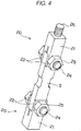
- Fig. 4 is an outline diagram of a jig 20 for an ultrasonic fatigue testing machine according to the invention.
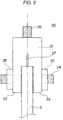
- Fig. 5 is a front outline diagram of the jig 20 for the ultrasonic fatigue testing machine according to the invention.
- the jig 20 includes a main body portion 21 and a pair of grip portions 22 which sandwiches the end of the test piece S by a pressing force.
- the main body portion 21 of the jig 20 at the connection side to the horn 6 is provided with a screw portion 26 which is connected to the front end of the horn 6 by the screw-connection.
- the pair of grip portions 22 is provided with a hole through which a screw 24 penetrating the test piece S and the grip portion 22 passes. Additionally, it is necessary to form a hole, through which the screw 24 passes, in the test piece S to be attached to the jig 20. Further, it is ideal that no gap is formed while the end of the test piece S is inserted between the pair of grip portions 22. In this embodiment, as illustrated in Fig.
- a split 27 is provided at a position of the main body portion 21 near the end of the test piece S, the inner surface of the grip portion 22 can be sufficiently brought into close contact with the side surface of the end of the test piece S by pressing the left and right two nuts 25 in a balanced manner and generating a pressing force to act on the test piece S.
- a spacer may be inserted between the inner surface of the grip portion 22 and the end of the test piece S.
- the spacer for example, soft metal such as aluminum used as a tab can be adopted.
- a user reliably clamps and holds the test piece S by the pair of grip portions 22 by fastening a nut 25 to both ends of the screw 24 and operating the screw 24 and the nut 25 so that the centers of gravity of the pair of jigs 20 are aligned to the line passing through the center portion of the test piece S.
- the center of gravity of the jig 20 is aligned to the center of gravity of the test piece S, unnecessary lateral resonance can be prevented.
- the jig 20 of the second embodiment is fixed to the test piece S by a screw differently from the jig 10 of the first embodiment, the test piece S can be repeatedly used while being replaced.
- the jig 20 When a test starts by connecting the jig 20 to the front end of the horn 6 while the pair of jigs 20 is attached to both ends of the test piece S, the jig 20 is resonated along with the test piece S. That is, the test piece S and the jig 20 are entirely resonated at the test frequency.
- the weight of the jig 20 is adjusted as described above, the substantial mass of both ends of the test piece S can be set to be sufficiently larger than that of the center portion so that stress at the center portion of the test piece S becomes a target value.
- the length of the test piece S is determined in consideration of the weight of the jig 20 so that the connection portion between the horn 6 and the jig 20 becomes an antinode of the displacement vibration and the center portion of the test piece S becomes a node of the displacement vibration.
- the screw 24 and the nut 25 are used as a pressing force generation member for pressing the pair of grip portions 22 against the test piece S and the weight of the jig 20 is changed by the nut 25.
- the jig 20 may be provided as a pair of jigs such that the weight of the main body portion 21 of the jig 20 is different and may be replaced for the test piece S in response to a desired resonance frequency or target stress applied to the center portion of the test piece S.
- the adjustment plate 13a, 13b, 14a, or 14b may be inserted into the pair of jigs 20 to adjust the weight as in the case of the first embodiment illustrated in Fig. 3 .
- Fig. 6 is a front outline diagram of a jig 30 for an ultrasonic fatigue testing machine according to a third embodiment of the invention.
- the same members as those in the second embodiment are denoted by the same reference numerals and a detailed description thereof will be omitted.
- the jig 30 of the embodiment includes a pair of screws 34 instead of the screw 24.
- the screw 34 is, for example, a hexagon socket stop screw, a slit stop screw, or the like and can be tightened using a tool.
- Each of the left and right grip portions 22 is provided with a screw hole into which the screw 34 is threaded.
- a spacer 33 contacting the side surface of the end of the test piece S is disposed at the front end of the screw 34.
- the jig 30 is used when it is difficult to process a hole through which the screw 24 passes at both ends of the test piece S.
- the user clamps and holds the test piece S to the pair of grip portions 22 by operating each of the screws 34 threaded into the screw holes formed in the pair of grip portions 22 in a balanced manner and bringing the spacer 33 into close contact with the side surfaces of both ends of the test piece S so that a pressing force acts thereon.
- the nut 25 is used to adjust the weight of the jig 30.
- the test piece S is clamped by the screw 34 and the nut is threaded into the screw 34 so that the test piece is fixed against the outer surface of the grip portion 22. Accordingly, it is possible to adjust the weight of the jig 30 by using the nuts 25 each having a different thickness.
- the screw 34 is used as a pressing force generation member that presses the pair of grip portions 22 against the test piece S and the weight of the jig 20 is changed by the nut 25.
- a bolt may be employed instead of the screw 34 and the nut 25. Even when the size of the bolt head is changed, the weight of the jig 30 can be changed.
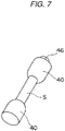
- Fig. 7 is an outline diagram of a jig 40 for an ultrasonic fatigue testing machine according to a fourth embodiment of the invention and Fig. 8 is a cross-sectional outline diagram thereof.
- Fig. 8(a) illustrates the jig 40 which holds the test piece S by shrink fitting, crimping, or fixing such as welding, brazing, or adhering
- Fig. 8(b) illustrates a modified example of the jig 40 which holds the test piece S by the screw 44.
- the jig 40 of the embodiment is used to hold the test piece S called a steel wire.
- the test piece S it is not practical to prepare the test piece S having a bent shape at the center portion as described with reference to Fig. 9 when performing a test on the steel wire.
- One end of the jig 40 is provided with a screw portion 46 to be connected to the horn 6 and the other end thereof is provided with a hole into which the front end of the test piece S is insertable as illustrated in Fig. 8(a) . Additionally, since the inner wall of the hole is in close contact with the side surface of the test piece S, this hole serves as the grip portion of the invention. That is, the end of the test piece S is inserted into the hole and the jig 40 is attached to the test piece S by shrink fitting, crimping, or fixing such as welding, brazing, or adhering. Further, as illustrated in Fig.
- the test piece S may be held by the jig 40 in such a manner that a screw hole is provided at the side portion of the jig 40 so as to perpetrate the inner wall of the hole and the screw 44 is inserted so that the front end of the screw 44 is in close contact with the side surface of the test piece S.
- the weight can be adjusted by inserting the adjustment plate 13a, 13b, 14a, or 14b into the pair of jigs 40.
- the test piece S can be easily manufactured.
- a plate-shaped test piece processed into a shape for a general static tensile test can be used for an ultrasonic fatigue test depending on the material.
Landscapes
- Physics & Mathematics (AREA)
- General Physics & Mathematics (AREA)
- Biochemistry (AREA)
- Life Sciences & Earth Sciences (AREA)
- Chemical & Material Sciences (AREA)
- Analytical Chemistry (AREA)
- Health & Medical Sciences (AREA)
- General Health & Medical Sciences (AREA)
- Immunology (AREA)
- Pathology (AREA)
- Engineering & Computer Science (AREA)
- Aviation & Aerospace Engineering (AREA)
- Acoustics & Sound (AREA)
- Electromagnetism (AREA)
- Investigating Strength Of Materials By Application Of Mechanical Stress (AREA)
Abstract
A pair of jigs has the same mass and a weight is adjusted in consideration of a test piece shape so that stress of a center portion of a test piece becomes a desired value. That is, the jig serves as a weight adjustment tool for adjusting a resonance frequency and stress of the test piece. The upper and lower jigs are attached to both ends of the test piece S so that the center of gravity of the upper jig and the center of gravity of the lower jig are located on a perpendicular line passing through the center portion of the test piece.
Description
- The present invention relates to a jig for an ultrasonic fatigue testing machine attached to a test piece when performing a fatigue test by resonating the test piece using an ultrasonic wave.
- In an ultrasonic fatigue test in which a vibration is applied to a test piece by using ultrasonic waves to evaluate a fatigue life of a material, stress is repeatedly applied to the test piece by resonating the test piece with, for example, a sinusoidal vibration of 20 kHz. In an ultrasonic fatigue testing machine, an ultrasonic vibration generated from an ultrasonic transducer is amplified by a horn and is transmitted to the test piece. For this reason, there is a need to reliably attach the test piece to the horn. From the viewpoint of the transmission property of the vibration energy, the test piece is attached to the horn by screw-connection (see Patent Literature 1).
-
Fig. 9 is an explanatory diagram illustrating a relationship of a shape of an annular test piece of the related art with respect to stress curve and an amplitude curve. In this drawing, an annular test piece is illustrated on the left side of the drawing and an axial stress curve P indicated by a dashed line and a displacement curve E indicated by a solid line are illustrated on the right side of the drawing. - A test piece for an ultrasonic fatigue test needs to have the same resonance frequency as the ultrasonic vibration generated from the ultrasonic transducer. Thus, as illustrated in
Fig. 9 , a shape of the test piece is designed such that stress amplification becomes zero at a test piece attachment position B in the horn (becomes an antinode of a displacement vibration) and stress amplification becomes maximal at a center position C of the test piece (becomes a node of the displacement vibration). - [Patent Literature 1]
JP-A-5-87719 - In the case of a metal material, a male screw corresponding to a female screw formed at a front end of the horn is integrally formed with a body of the test piece at the time of manufacturing the test piece by processing the material (see
Fig. 9 of Patent Literature 1). The ultrasonic fatigue testing machine is designed for a standard annular test piece. Accordingly, even when a plate-shaped test piece is manufactured for an ultrasonic fatigue test, a male screw having a screw diameter corresponding to the female screw of the horn needs to be formed similarly to the annular test piece. It is desirable to use a material in which the plate thickness of the plate-shaped test piece is sufficiently thicker than the screw diameter, but when the test piece having the plate thickness thinner than the screw diameter needs to be manufactured, the screw needs to be processed with high accuracy. As a result, it is difficult to manufacture the plate-shaped test piece. - In recent years, a fatigue test with high stress of 1000 MPa is desired for high-strength steel. When a test is performed on the plate-shaped test piece by an ultrasonic fatigue testing machine designed for a general annular test piece, the mass of both ends of the test piece in the plate shape is smaller than that of the annular shape. Accordingly, when the width dimension ratio is the same at the center portion and both ends of the test piece, stress at the center potion during resonance becomes smaller than a half of the stress of the annular test piece.
-
Fig. 10 is a diagram illustrating a resonance simulation of a plate-shaped test piece model. Additionally,Fig. 10 illustrates a 1/2 model in which the plate-shaped test piece designed so that stress at the center portion during resonance becomes the same as that of the annular test piece is cut at the center portion thereof.Fig. 10(a) illustrates a state before the resonance occurs.Fig. 10(b) illustrates a state where a maximal sinusoidal stress waveform which can be realized by a general ultrasonic fatigue testing machine is applied to the test piece, where the test piece before the resonance occurs is indicated by a dashed line and the test piece having a lateral vibration during resonance is indicated by a solid line. - The plate-shaped test piece of
Fig. 10 is designed so that the stress at the center portion is the same as that of the annular test piece by a configuration in which the width dimensions at both ends are larger than the diameter of the center portion. In a normal test, the test piece is vibrated longitudinally in parallel to the wave traveling direction (a direction of an arrow A ofFig. 10(a) ). However, in the plate-shaped test piece, a lateral vibration occurs at frequencies close to longitudinal vibration as indicated by a solid line inFig. 10 (b) and thus a normal test is hindered. In this way, there is a case where the plate-shaped test piece corresponding to high stress is not easily manufactured. - As described above, there is a limit to the method of processing a material itself so that the mass of both ends of the test piece is sufficiently larger than that of the center portion of the test piece in order to apply desired stress to the center portion of the test piece. Meanwhile, there is also a material which cannot be easily processed into the shape of the test piece. As such a material, for example, there are composite materials such as carbon fiber reinforced plastic (CFRP) which is being developed in recent years. In the composite materials, it is difficult to process the material into a test piece shape for a conventional ultrasonic fatigue test by directly threading the material or tapping the material in parallel to the fiber laminating direction. As a result, it is difficult to manufacture a test piece corresponding to high stress.
- The invention has been made to solve the above-described problems and an object of the invention is to provide a jig for an ultrasonic fatigue testing machine capable of facilitating a design of a test piece formed of various materials and performing a fatigue test in which high stress is repeatedly applied to a test piece.
- According to the invention, there is provided a jig for an ultrasonic fatigue testing machine used in a fatigue test in which a vibration generated from an ultrasonic transducer is amplified by a horn and a test piece connected to a front end of the horn is resonated, including: a main body portion; and a grip portion holding an end of the test piece, in which the jig is attached to both ends of the test piece to adjust the mass of both ends of the test piece.
- According to the invention, there is provided the jig for the ultrasonic fatigue testing machine of
claim 1, in which an end of the main body portion opposite to the grip portion is provided with a screw portion to be connected to the horn. - According to the invention, there is provided the jig for the ultrasonic fatigue testing machine of
claim 1, in which when an end of the main body portion is connected to the horn, an adjustment plate is inserted between the main body portion and the horn, and when the end of the main body portion serves as a free end, the adjustment plate is attached to the free end to adjust the mass of both ends of the test piece. - According to the invention, there is provided the jig for the ultrasonic fatigue testing machine of
claim 1, in which the grip portion includes a pressing force generation member that sandwiches the end of the test piece by a pressing force using a screw when holding the end of the test piece. - According to the invention, there is provided the jig for the ultrasonic fatigue testing machine of
claim 4, in which the mass of both ends of the test piece is adjusted by changing the weight of the pressing force generation member. - According to the invention, since the jig for the ultrasonic fatigue testing machine is attached to both ends of the test piece, it is possible to increase the mass near the end of the test piece. Accordingly, since it is possible to increase the mass near the end of the test piece in relation to the center portion of the test piece without increasing the mass of the end of the test piece itself, it is possible to repeatedly apply high stress as a target value to the center portion of the test piece. Thus, it is possible to perform a fatigue test with high stress of 1000 MPa for the test piece even in a current device without increasing the capacity of the ultrasonic fatigue testing machine designed for the annular test piece. Further, since the jig for the ultrasonic fatigue testing machine is attached to both ends of the test piece, it is not necessary to provide the screw portion to be connected to the horn of the ultrasonic fatigue testing machine at the test piece itself when manufacturing the test piece and it is possible to perform an ultrasonic fatigue test for a material which is not easily subjected to threading. If the jig for the ultrasonic fatigue testing machine is prepared as a pair of jigs each having a different weight, even when the accuracy of the desired resonance frequency is not obtained in the test piece manufactured according to a length obtained by a calculation, it is possible to easily adjust the resonance frequency by replacing the jig for the ultrasonic fatigue testing machine attached to the test piece with another jig having a different weight since the resonance frequency ω is √(spring constant/mass) in a simple spring-mass system. For this reason, since there is no need to determine an optimal test piece length by measuring each resonance frequency after manufacturing test pieces each having a different length as in the related art, it is possible to easily manufacture the test piece.
- According to the invention, since the mass of both ends of the test piece is adjusted by the adjustment plate, it is possible to easily and finely adjust the resonance frequency corresponding to target stress applied to the center portion of the test piece by adjusting the number of the adjustment plates or the thickness thereof.
- According to the invention, it is possible to repeatedly use the pair of jigs for the ultrasonic fatigue testing machine while replacing the test piece.
- According to the invention, since it is possible to change the weight of the pressing force generation member in response to the target stress applied to the center portion of the test piece, it is possible to more easily change the weight of the jig for the ultrasonic fatigue testing machine and thus to finely adjust the resonance frequency of the test piece.
-
-
Fig. 1 is an outline diagram of an ultrasonic fatigue testing machine which performs a fatigue test by attaching ajig 10 for the ultrasonic fatigue testing machine according to the invention thereto; -
Fig. 2 is an outline diagram of thejig 10 for the ultrasonic fatigue testing machine according to the invention; -
Fig. 3 is an outline diagram illustrating a weight adjustment of thejig 10 for the ultrasonic fatigue testing machine; -
Fig. 4 is an outline diagram of ajig 20 for an ultrasonic fatigue testing machine according to a second embodiment of the invention; -
Fig. 5 is a front outline diagram of thejig 20 for the ultrasonic fatigue testing machine according to the second embodiment of the invention; -
Fig. 6 is a front outline diagram of ajig 30 for an ultrasonic fatigue testing machine according to a third embodiment of the invention; -
Fig. 7 is an outline diagram of ajig 40 for an ultrasonic fatigue testing machine according to a fourth embodiment of the invention; -
Fig. 8 is a cross-sectional outline diagram of thejig 40 for the ultrasonic fatigue testing machine according to the fourth embodiment of the invention; -
Fig. 9 is an explanatory diagram illustrating a relationship of a shape of a conventional annular test piece with respect to a stress curve and an amplitude curve; and -
Fig. 10 is a diagram illustrating a resonance simulation of a plate-shaped test piece model. - Hereinafter, embodiments of the invention will be described with reference to the drawings.
Fig. 1 is an outline diagram of an ultrasonic fatigue testing machine which performs a fatigue test by attaching ajig 10 for the ultrasonic fatigue testing machine according to the invention thereto. - The ultrasonic fatigue testing machine is used to perform a fatigue test by resonating a test piece S using ultrasonic waves and includes a
vibration portion 7 which includes anultrasonic transducer 5 vibrated by a signal generated from anoscillator 3 and ahorn 6 amplifying a vibration and transmitting the vibration to the test piece S and aframe 1 which is attached to thevibration portion 7. Theoscillator 3 generates the signal based on a test frequency set by acontrol unit 2. The arrangement of the vibration portion 13 and the test piece S illustrated inFig. 1 is set to perform a fatigue test in which a longitudinal vibration is applied to the test piece S. - The test piece S is a plate-shaped test piece and both ends thereof are sandwiched by a pair of
jigs 10 for the ultrasonic fatigue testing machine (hereinafter, thejig 10 for the ultrasonic fatigue testing machine will be referred to as the "jig 10" if necessary in the specification). The pair ofjigs 10 has the same mass and the mass is adjusted in consideration of the test piece shape so that the stress at the center portion of the test piece S becomes a desired value (target stress) within the ability range of the device. That is, thejig 10 serves as a weight adjustment tool for adjusting the resonance frequency and the stress of the test piece S. In order to adjust the weight, the length or width of thejig 10 may be adjusted. The upper andlower jigs 10 are attached to both ends of the test piece S so that the center of gravity of theupper jig 10 and the center of gravity of thelower jig 10 are located on a vertical line passing through the center portion of the test piece S. When the upper andlower jigs 10 and the test piece S are aligned to one another at the center of gravity thereof, it is possible to prevent the unnecessary lateral resonance. Theupper jig 10 is connected to thehorn 6 by the screw-connection. Thelower jig 10 is connected to thehorn 6 fixed to theframe 1 by the screw-connection. In the example ofFig. 1 , thelower jig 10 is also connected to thehorn 6 resonated at the same cycle in order to apply average stress to the test piece S. Additionally, thelower jig 10 may be a free end according to the purpose of the test. Further, in the example ofFig. 1 , a longitudinal vibration is applied to the test piece S from the upper side of the test piece S, but when a vibration is applied to the test piece S from the upper and lower sides of theframe 1, thehorn 6 connected to thelower jig 10 is also connected to theultrasonic transducer 5 and theoscillator 3. -
Fig. 2 is an outline diagram of thejig 10 for the ultrasonic fatigue testing machine according to the invention. - The
jig 10 includes amain body portion 11 and a pair ofgrip portions 12 which sandwiches the end of the test piece S. An end (an end surface) of themain body portion 11 of thejig 10 at a connection side to thehorn 6 and a side opposite to thegrip portion 12 is provided with ascrew portion 16 which is connected to the front end of thehorn 6 by the screw-connection. The end of the test piece S is inserted between the pair ofgrip portions 12 and the test piece S and thejig 10 are integrally held by shrink fitting, crimping, or fixing such as welding, brazing, or adhering. Additionally, the pair ofjigs 10 is attached to the test piece S so that the centers of gravity of the pair ofjigs 10 are aligned to the line passing through the center portion of the test piece S. -
Fig. 3 is an outline diagram illustrating a weight adjustment of thejig 10 for the ultrasonic fatigue testing machine.Fig. 3(a) illustrates the weight adjustment of thejig 10 connected to thehorn 6 by the screw-connection andFig. 3(b) illustrates the weight adjustment when thelower jig 10 is a free end. - The pair of
jigs 10 is prepared to have the same mass according to the size of the test piece S. Meanwhile, in theprepared jig 10, there is a case where the weight is insufficient for the stress at the center portion of the test piece S to become a desired value (target stress). In such a case, as illustrated inFig. 3 , the weight of the pair ofjigs 10 is adjusted. - Even when the accuracy of the desired resonance frequency is not obtained at the test piece S prepared to have a length obtained by a calculation, the weight of the
jig 10 is adjusted. In this way, when thejig 10 is attached to the test piece S, the substantial mass of both ends of the test piece S can be set to be sufficiently larger than that of the center portion so that stress at the center portion of the test piece S becomes a target value. In this embodiment, a plurality ofadjustment plates adjustment plates screw portion 16 passes. Then, theadjustment plates horn 6 and thejig 10 so that the weight of both ends of the test piece S is adjusted. Additionally, when thelower jig 10 is not connected to thehorn 6 and is used as a free end, an end surface of thejig 10 is provided with a male screw and theadjustment plates bolt 15 as illustrated inFig. 3(b) . - When a test starts by connecting the
jig 10 to the front end of thehorn 6 while the pair ofjigs 10 is attached to both ends of the test piece S, thejig 10 is resonated along with the test piece S. As in the related art, it is not necessary to process the test piece S to be directly connected to thehorn 6. Then, the length of the test piece S is determined in consideration of the weight of thejig 10 so that the connection portion between thehorn 6 and thejig 10 becomes the antinode of the displacement vibration and the center portion of the test piece S becomes the node of the displacement vibration. -
Fig. 4 is an outline diagram of ajig 20 for an ultrasonic fatigue testing machine according to the invention.Fig. 5 is a front outline diagram of thejig 20 for the ultrasonic fatigue testing machine according to the invention. - The
jig 20 includes amain body portion 21 and a pair ofgrip portions 22 which sandwiches the end of the test piece S by a pressing force. Themain body portion 21 of thejig 20 at the connection side to thehorn 6 is provided with ascrew portion 26 which is connected to the front end of thehorn 6 by the screw-connection. The pair ofgrip portions 22 is provided with a hole through which ascrew 24 penetrating the test piece S and thegrip portion 22 passes. Additionally, it is necessary to form a hole, through which thescrew 24 passes, in the test piece S to be attached to thejig 20. Further, it is ideal that no gap is formed while the end of the test piece S is inserted between the pair ofgrip portions 22. In this embodiment, as illustrated inFig. 5 , since asplit 27 is provided at a position of themain body portion 21 near the end of the test piece S, the inner surface of thegrip portion 22 can be sufficiently brought into close contact with the side surface of the end of the test piece S by pressing the left and right twonuts 25 in a balanced manner and generating a pressing force to act on the test piece S. Additionally, a spacer may be inserted between the inner surface of thegrip portion 22 and the end of the test piece S. As the spacer, for example, soft metal such as aluminum used as a tab can be adopted. - A user reliably clamps and holds the test piece S by the pair of
grip portions 22 by fastening anut 25 to both ends of thescrew 24 and operating thescrew 24 and thenut 25 so that the centers of gravity of the pair ofjigs 20 are aligned to the line passing through the center portion of the test piece S. In this way, when the center of gravity of thejig 20 is aligned to the center of gravity of the test piece S, unnecessary lateral resonance can be prevented. Additionally, since thejig 20 of the second embodiment is fixed to the test piece S by a screw differently from thejig 10 of the first embodiment, the test piece S can be repeatedly used while being replaced. - When a test starts by connecting the
jig 20 to the front end of thehorn 6 while the pair ofjigs 20 is attached to both ends of the test piece S, thejig 20 is resonated along with the test piece S. That is, the test piece S and thejig 20 are entirely resonated at the test frequency. When the weight of thejig 20 is adjusted as described above, the substantial mass of both ends of the test piece S can be set to be sufficiently larger than that of the center portion so that stress at the center portion of the test piece S becomes a target value. For this reason, in the existing ultrasonic fatigue testing machine, it is possible to perform a test for a material which cannot be easily subjected to a fatigue test of repeatedly applying high stress to the center portion of the test piece S without spending time and effort for manufacturing the test piece S and designing the test piece shape. - As in the related art, there is no need to process the test piece S so that the test piece is directly connected to the
horn 6. Then, the length of the test piece S is determined in consideration of the weight of thejig 20 so that the connection portion between thehorn 6 and thejig 20 becomes an antinode of the displacement vibration and the center portion of the test piece S becomes a node of the displacement vibration. In this embodiment, it is possible to easily change the height dimension of thenut 25, the length of thescrew 24, the thickness of thenut 25 fastened to thescrew 24, or the mass of both ends of the test piece S including thejig 20 connected to the front end of thehorn 6 as the number increases or decreases. Thus, it is possible to adjust the weight of thejig 20 by changing the weight of the separable member such as thescrew 24 or thenut 25 even when the accuracy of the desired resonance frequency is not obtained with the length of the test piece S obtained by a calculation. - In this way, in the
jig 20 ofFig. 5 , thescrew 24 and thenut 25 are used as a pressing force generation member for pressing the pair ofgrip portions 22 against the test piece S and the weight of thejig 20 is changed by thenut 25. Additionally, thejig 20 may be provided as a pair of jigs such that the weight of themain body portion 21 of thejig 20 is different and may be replaced for the test piece S in response to a desired resonance frequency or target stress applied to the center portion of the test piece S. Further, theadjustment plate jigs 20 to adjust the weight as in the case of the first embodiment illustrated inFig. 3 . -
Fig. 6 is a front outline diagram of ajig 30 for an ultrasonic fatigue testing machine according to a third embodiment of the invention. The same members as those in the second embodiment are denoted by the same reference numerals and a detailed description thereof will be omitted. - The
jig 30 of the embodiment includes a pair ofscrews 34 instead of thescrew 24. Thescrew 34 is, for example, a hexagon socket stop screw, a slit stop screw, or the like and can be tightened using a tool. Each of the left andright grip portions 22 is provided with a screw hole into which thescrew 34 is threaded. Aspacer 33 contacting the side surface of the end of the test piece S is disposed at the front end of thescrew 34. At in the case of attaching thejig 20 of the second embodiment, thejig 30 is used when it is difficult to process a hole through which thescrew 24 passes at both ends of the test piece S. The user clamps and holds the test piece S to the pair ofgrip portions 22 by operating each of thescrews 34 threaded into the screw holes formed in the pair ofgrip portions 22 in a balanced manner and bringing thespacer 33 into close contact with the side surfaces of both ends of the test piece S so that a pressing force acts thereon. Then, thenut 25 is used to adjust the weight of thejig 30. Here, the test piece S is clamped by thescrew 34 and the nut is threaded into thescrew 34 so that the test piece is fixed against the outer surface of thegrip portion 22. Accordingly, it is possible to adjust the weight of thejig 30 by using thenuts 25 each having a different thickness. - Additionally, in the
jig 30 ofFig. 6 , thescrew 34 is used as a pressing force generation member that presses the pair ofgrip portions 22 against the test piece S and the weight of thejig 20 is changed by thenut 25. However, a bolt may be employed instead of thescrew 34 and thenut 25. Even when the size of the bolt head is changed, the weight of thejig 30 can be changed. -
Fig. 7 is an outline diagram of ajig 40 for an ultrasonic fatigue testing machine according to a fourth embodiment of the invention andFig. 8 is a cross-sectional outline diagram thereof. In addition,Fig. 8(a) illustrates thejig 40 which holds the test piece S by shrink fitting, crimping, or fixing such as welding, brazing, or adhering andFig. 8(b) illustrates a modified example of thejig 40 which holds the test piece S by thescrew 44. - The
jig 40 of the embodiment is used to hold the test piece S called a steel wire. Here, it is not practical to prepare the test piece S having a bent shape at the center portion as described with reference toFig. 9 when performing a test on the steel wire. However, even in the steel wire of which the center portion is difficult to be bent thinner, it is possible to apply high stress to the center portion of the test piece S by additionally attaching thejig 40 to both ends as illustrated inFig. 7 . - One end of the
jig 40 is provided with ascrew portion 46 to be connected to thehorn 6 and the other end thereof is provided with a hole into which the front end of the test piece S is insertable as illustrated inFig. 8(a) . Additionally, since the inner wall of the hole is in close contact with the side surface of the test piece S, this hole serves as the grip portion of the invention. That is, the end of the test piece S is inserted into the hole and thejig 40 is attached to the test piece S by shrink fitting, crimping, or fixing such as welding, brazing, or adhering. Further, as illustrated inFig. 8(b) , the test piece S may be held by thejig 40 in such a manner that a screw hole is provided at the side portion of thejig 40 so as to perpetrate the inner wall of the hole and thescrew 44 is inserted so that the front end of thescrew 44 is in close contact with the side surface of the test piece S. Further, as in the case of the first embodiment illustrated inFig. 3 , the weight can be adjusted by inserting theadjustment plate jigs 40. - When the
jigs -
- 1
- frame
- 2
- control unit
- 3
- oscillator
- 5
- ultrasonic transducer
- 6
- horn
- 7
- vibration portion
- 10
- jig
- 11
- main body portion
- 12
- grip portion
- 16
- screw portion
- 20
- jig
- 21
- main body portion
- 22
- grip portion
- 24
- screw
- 25
- nut
- 26
- screw portion
- 27
- split
- 30
- jig
- 33
- spacer
- 34
- screw
- 40
- jig
- 44
- screw
- 46
- screw portion
- S
- test piece
Claims (5)
- A jig for an ultrasonic fatigue testing machine used in a fatigue test in which a vibration generated from an ultrasonic transducer is amplified by a horn and a test piece connected to a front end of the horn is resonated, comprising:a main body portion; anda grip portion holding an end of the test piece,wherein the jig is attached to both ends of the test piece to adjust the mass of both ends of the test piece.
- The jig for the ultrasonic fatigue testing machine according to claim 1,
wherein an end of the main body portion opposite to the grip portion is provided with a screw portion to be connected to the horn. - The jig for the ultrasonic fatigue testing machine according to claim 1,
wherein when an end of the main body portion is connected to the horn, an adjustment plate is inserted between the main body portion and the horn, and
when the end of the main body portion serves as a free end, the adjustment plate is attached to the free end to adjust the mass of both ends of the test piece. - The jig for the ultrasonic fatigue testing machine according to claim 1,
wherein the grip portion includes a pressing force generation member that sandwiches the end of the test piece by a pressing force using a screw when holding the end of the test piece. - The jig for the ultrasonic fatigue testing machine according to claim 4,
wherein the mass of both ends of the test piece is adjusted by changing the weight of the pressing force generation member.
Applications Claiming Priority (1)
| Application Number | Priority Date | Filing Date | Title |
|---|---|---|---|
| JP2017179086A JP2019053009A (en) | 2017-09-19 | 2017-09-19 | Jig for ultrasonic fatigue testing machine |
Publications (1)
| Publication Number | Publication Date |
|---|---|
| EP3460465A1 true EP3460465A1 (en) | 2019-03-27 |
Family
ID=63490253
Family Applications (1)
| Application Number | Title | Priority Date | Filing Date |
|---|---|---|---|
| EP18192109.9A Withdrawn EP3460465A1 (en) | 2017-09-19 | 2018-08-31 | Jig for ultrasonic fatigue testing machine |
Country Status (4)
| Country | Link |
|---|---|
| US (1) | US20190086307A1 (en) |
| EP (1) | EP3460465A1 (en) |
| JP (1) | JP2019053009A (en) |
| CN (1) | CN109520825A (en) |
Families Citing this family (14)
| Publication number | Priority date | Publication date | Assignee | Title |
|---|---|---|---|---|
| CN109765129A (en) * | 2019-03-22 | 2019-05-17 | 吉林大学 | A resonant system that can realize multi-axis ultrasonic fatigue test |
| CN113884260B (en) * | 2020-07-01 | 2024-04-19 | 中国航发商用航空发动机有限责任公司 | Vibration level amplifying vibration fatigue test fixture |
| CN111693371A (en) * | 2020-07-06 | 2020-09-22 | 上海大学绍兴研究院 | Test fixture for testing tensile property of ceramic matrix composite |
| CN112113847A (en) * | 2020-10-20 | 2020-12-22 | 河南理工大学 | Two-dimensional ultrasonic vibration tensile test device |
| CN112666018A (en) * | 2020-11-03 | 2021-04-16 | 四川大学 | Ultrasonic frequency mechanical loading fatigue test system for dissimilar metal welded joint |
| CN112881160B (en) * | 2021-01-12 | 2023-01-17 | 中国商用飞机有限责任公司北京民用飞机技术研究中心 | Fixture for fatigue test of metal wide plate |
| CN115655674B (en) * | 2021-07-07 | 2025-11-25 | 中国航发商用航空发动机有限责任公司 | Vibration fatigue testing device |
| CN114324025B (en) * | 2021-12-23 | 2025-05-30 | 中车株洲电机有限公司 | Welded structure fatigue life test device and method |
| CN114577591A (en) * | 2022-02-23 | 2022-06-03 | 华东理工大学 | Fatigue test fixture for plate-shaped sample |
| JP7789598B2 (en) * | 2022-03-18 | 2025-12-22 | 日本発條株式会社 | Ultrasonic fatigue testing machine and ultrasonic fatigue testing method |
| CN114942180A (en) * | 2022-03-25 | 2022-08-26 | 华东理工大学 | Multifunctional fatigue test fixture suitable for different fatigue testing machines |
| CN115420592A (en) * | 2022-11-07 | 2022-12-02 | 清华大学 | Eccentric loading auxiliary device for metal fatigue test |
| DE102023000033A1 (en) * | 2023-01-10 | 2024-07-11 | Technische Universität Dortmund, Körperschaft des öffentlichen Rechts | Test device and method for assessing the fatigue behaviour of a material on flat specimens using ultrasound |
| JP2024116756A (en) * | 2023-02-16 | 2024-08-28 | 日本発條株式会社 | Vibration adjustment method, ultrasonic fatigue test method, and ultrasonic fatigue test machine |
Citations (7)
| Publication number | Priority date | Publication date | Assignee | Title |
|---|---|---|---|---|
| JPS58211627A (en) * | 1982-06-03 | 1983-12-09 | Mitsubishi Heavy Ind Ltd | Fatigue crack inserting method |
| JPS63210747A (en) * | 1987-02-27 | 1988-09-01 | Ngk Spark Plug Co Ltd | Ceramic sample holding means for durability testing jig |
| JPH01112447U (en) * | 1988-01-26 | 1989-07-28 | ||
| JPH0587719A (en) | 1991-03-27 | 1993-04-06 | Ngk Insulators Ltd | Ultrasonic fatigue testing tool for ceramic |
| JPH05164667A (en) * | 1991-12-12 | 1993-06-29 | Mitsubishi Heavy Ind Ltd | Surface crack progress measuring method |
| JP2013221872A (en) * | 2012-04-17 | 2013-10-28 | Shimadzu Corp | Test piece gripping tool |
| CN108627572A (en) * | 2018-05-10 | 2018-10-09 | 江苏大学 | Ultrasonic breaking test apparatus and method |
Family Cites Families (3)
| Publication number | Priority date | Publication date | Assignee | Title |
|---|---|---|---|---|
| JP4883307B2 (en) * | 2007-07-04 | 2012-02-22 | 株式会社島津製作所 | Material testing machine |
| KR101877596B1 (en) * | 2011-07-22 | 2018-08-09 | 사프란 에어크래프트 엔진 | An apparatus and method for carrying out in a controlled atmosphere material fatigue tests in a high cycle regime with a controlled strain ratio |
| WO2015019446A1 (en) * | 2013-08-07 | 2015-02-12 | 株式会社島津製作所 | Material testing machine and jig mounting apparatus |
-
2017
- 2017-09-19 JP JP2017179086A patent/JP2019053009A/en not_active Withdrawn
-
2018
- 2018-06-12 US US16/005,902 patent/US20190086307A1/en not_active Abandoned
- 2018-08-31 EP EP18192109.9A patent/EP3460465A1/en not_active Withdrawn
- 2018-09-17 CN CN201811080389.XA patent/CN109520825A/en not_active Withdrawn
Patent Citations (7)
| Publication number | Priority date | Publication date | Assignee | Title |
|---|---|---|---|---|
| JPS58211627A (en) * | 1982-06-03 | 1983-12-09 | Mitsubishi Heavy Ind Ltd | Fatigue crack inserting method |
| JPS63210747A (en) * | 1987-02-27 | 1988-09-01 | Ngk Spark Plug Co Ltd | Ceramic sample holding means for durability testing jig |
| JPH01112447U (en) * | 1988-01-26 | 1989-07-28 | ||
| JPH0587719A (en) | 1991-03-27 | 1993-04-06 | Ngk Insulators Ltd | Ultrasonic fatigue testing tool for ceramic |
| JPH05164667A (en) * | 1991-12-12 | 1993-06-29 | Mitsubishi Heavy Ind Ltd | Surface crack progress measuring method |
| JP2013221872A (en) * | 2012-04-17 | 2013-10-28 | Shimadzu Corp | Test piece gripping tool |
| CN108627572A (en) * | 2018-05-10 | 2018-10-09 | 江苏大学 | Ultrasonic breaking test apparatus and method |
Also Published As
| Publication number | Publication date |
|---|---|
| US20190086307A1 (en) | 2019-03-21 |
| JP2019053009A (en) | 2019-04-04 |
| CN109520825A (en) | 2019-03-26 |
Similar Documents
| Publication | Publication Date | Title |
|---|---|---|
| US20190086307A1 (en) | Jig for ultrasonic fatigue testing machine | |
| US3368085A (en) | Sonic transducer | |
| US8950458B2 (en) | System and method for mounting ultrasonic tools | |
| JP4820786B2 (en) | Impact tensile stress measurement method | |
| GB1599461A (en) | Ultrasonic transducer | |
| US8113258B2 (en) | Ultrasonic welding device | |
| US8025087B2 (en) | Ultrasonic vibration welder | |
| JP6454715B2 (en) | Ultrasonic bonding equipment | |
| JP2017504301A (en) | Converter unit | |
| US10054181B2 (en) | Damping component and damping structure | |
| Mostafavi et al. | Detection of terminal oscillation pattern in ultrasonic metal welding | |
| JP6296860B2 (en) | Fretting fatigue test method and fretting fatigue test apparatus | |
| JP6275859B2 (en) | Ultrasonic machining device with force sensor | |
| JP7789598B2 (en) | Ultrasonic fatigue testing machine and ultrasonic fatigue testing method | |
| JP2007278779A (en) | Test method for thermal fatigue, test piece for thermal fatigue test, and joint for mounting test piece for thermal fatigue test | |
| US4523710A (en) | Method for fabricating a fastener plate | |
| CN108593234A (en) | high-cycle fatigue test device and its application | |
| JP4795016B2 (en) | Fuel cell stack | |
| CN110455929B (en) | Non-resonance high-frequency vibration cracking test device and method | |
| KR102420483B1 (en) | Manual tools, bit and torque sensors used for them | |
| Kim et al. | Evaluation of welding performance of 20 kHz and 40 kHz ultrasonic metal welding | |
| JP3187918B2 (en) | Ultrasonic fatigue test jig for ceramics | |
| TW202124927A (en) | A sensing apparatus for sensing low frequency load and high frequency load | |
| Park et al. | Tensile strength of cu sheets welded by ultrasonic metal welding | |
| CN109719575B (en) | Non-metallic ultrasonic tool head for improving fatigue resistance by applying prestress |
Legal Events
| Date | Code | Title | Description |
|---|---|---|---|
| PUAI | Public reference made under article 153(3) epc to a published international application that has entered the european phase |
Free format text: ORIGINAL CODE: 0009012 |
|
| STAA | Information on the status of an ep patent application or granted ep patent |
Free format text: STATUS: REQUEST FOR EXAMINATION WAS MADE |
|
| 17P | Request for examination filed |
Effective date: 20180918 |
|
| AK | Designated contracting states |
Kind code of ref document: A1 Designated state(s): AL AT BE BG CH CY CZ DE DK EE ES FI FR GB GR HR HU IE IS IT LI LT LU LV MC MK MT NL NO PL PT RO RS SE SI SK SM TR |
|
| AX | Request for extension of the european patent |
Extension state: BA ME |
|
| STAA | Information on the status of an ep patent application or granted ep patent |
Free format text: STATUS: THE APPLICATION HAS BEEN WITHDRAWN |
|
| 18W | Application withdrawn |
Effective date: 20200529 |