EP3460390A1 - Displacement measurement device, measurement system, and displacement measurement method - Google Patents
Displacement measurement device, measurement system, and displacement measurement method Download PDFInfo
- Publication number
- EP3460390A1 EP3460390A1 EP18156150.7A EP18156150A EP3460390A1 EP 3460390 A1 EP3460390 A1 EP 3460390A1 EP 18156150 A EP18156150 A EP 18156150A EP 3460390 A1 EP3460390 A1 EP 3460390A1
- Authority
- EP
- European Patent Office
- Prior art keywords
- measurement target
- distance
- light beam
- sensor head
- target object
- Prior art date
- Legal status (The legal status is an assumption and is not a legal conclusion. Google has not performed a legal analysis and makes no representation as to the accuracy of the status listed.)
- Granted
Links
Images



Classifications
-
- G—PHYSICS
- G01—MEASURING; TESTING
- G01B—MEASURING LENGTH, THICKNESS OR SIMILAR LINEAR DIMENSIONS; MEASURING ANGLES; MEASURING AREAS; MEASURING IRREGULARITIES OF SURFACES OR CONTOURS
- G01B11/00—Measuring arrangements characterised by the use of optical techniques
- G01B11/02—Measuring arrangements characterised by the use of optical techniques for measuring length, width or thickness
- G01B11/06—Measuring arrangements characterised by the use of optical techniques for measuring length, width or thickness for measuring thickness ; e.g. of sheet material
-
- G—PHYSICS
- G01—MEASURING; TESTING
- G01S—RADIO DIRECTION-FINDING; RADIO NAVIGATION; DETERMINING DISTANCE OR VELOCITY BY USE OF RADIO WAVES; LOCATING OR PRESENCE-DETECTING BY USE OF THE REFLECTION OR RERADIATION OF RADIO WAVES; ANALOGOUS ARRANGEMENTS USING OTHER WAVES
- G01S17/00—Systems using the reflection or reradiation of electromagnetic waves other than radio waves, e.g. lidar systems
- G01S17/02—Systems using the reflection of electromagnetic waves other than radio waves
- G01S17/06—Systems determining position data of a target
- G01S17/46—Indirect determination of position data
-
- G—PHYSICS
- G01—MEASURING; TESTING
- G01B—MEASURING LENGTH, THICKNESS OR SIMILAR LINEAR DIMENSIONS; MEASURING ANGLES; MEASURING AREAS; MEASURING IRREGULARITIES OF SURFACES OR CONTOURS
- G01B11/00—Measuring arrangements characterised by the use of optical techniques
- G01B11/14—Measuring arrangements characterised by the use of optical techniques for measuring distance or clearance between spaced objects or spaced apertures
-
- G—PHYSICS
- G01—MEASURING; TESTING
- G01B—MEASURING LENGTH, THICKNESS OR SIMILAR LINEAR DIMENSIONS; MEASURING ANGLES; MEASURING AREAS; MEASURING IRREGULARITIES OF SURFACES OR CONTOURS
- G01B11/00—Measuring arrangements characterised by the use of optical techniques
- G01B11/02—Measuring arrangements characterised by the use of optical techniques for measuring length, width or thickness
-
- G—PHYSICS
- G01—MEASURING; TESTING
- G01B—MEASURING LENGTH, THICKNESS OR SIMILAR LINEAR DIMENSIONS; MEASURING ANGLES; MEASURING AREAS; MEASURING IRREGULARITIES OF SURFACES OR CONTOURS
- G01B11/00—Measuring arrangements characterised by the use of optical techniques
- G01B11/02—Measuring arrangements characterised by the use of optical techniques for measuring length, width or thickness
- G01B11/06—Measuring arrangements characterised by the use of optical techniques for measuring length, width or thickness for measuring thickness ; e.g. of sheet material
- G01B11/0608—Height gauges
-
- G—PHYSICS
- G01—MEASURING; TESTING
- G01B—MEASURING LENGTH, THICKNESS OR SIMILAR LINEAR DIMENSIONS; MEASURING ANGLES; MEASURING AREAS; MEASURING IRREGULARITIES OF SURFACES OR CONTOURS
- G01B21/00—Measuring arrangements or details thereof, where the measuring technique is not covered by the other groups of this subclass, unspecified or not relevant
- G01B21/02—Measuring arrangements or details thereof, where the measuring technique is not covered by the other groups of this subclass, unspecified or not relevant for measuring length, width, or thickness
- G01B21/04—Measuring arrangements or details thereof, where the measuring technique is not covered by the other groups of this subclass, unspecified or not relevant for measuring length, width, or thickness by measuring coordinates of points
- G01B21/042—Calibration or calibration artifacts
-
- G—PHYSICS
- G01—MEASURING; TESTING
- G01B—MEASURING LENGTH, THICKNESS OR SIMILAR LINEAR DIMENSIONS; MEASURING ANGLES; MEASURING AREAS; MEASURING IRREGULARITIES OF SURFACES OR CONTOURS
- G01B21/00—Measuring arrangements or details thereof, where the measuring technique is not covered by the other groups of this subclass, unspecified or not relevant
- G01B21/02—Measuring arrangements or details thereof, where the measuring technique is not covered by the other groups of this subclass, unspecified or not relevant for measuring length, width, or thickness
- G01B21/04—Measuring arrangements or details thereof, where the measuring technique is not covered by the other groups of this subclass, unspecified or not relevant for measuring length, width, or thickness by measuring coordinates of points
- G01B21/045—Correction of measurements
-
- G—PHYSICS
- G01—MEASURING; TESTING
- G01D—MEASURING NOT SPECIALLY ADAPTED FOR A SPECIFIC VARIABLE; ARRANGEMENTS FOR MEASURING TWO OR MORE VARIABLES NOT COVERED IN A SINGLE OTHER SUBCLASS; TARIFF METERING APPARATUS; MEASURING OR TESTING NOT OTHERWISE PROVIDED FOR
- G01D1/00—Measuring arrangements giving results other than momentary value of variable, of general application
- G01D1/14—Measuring arrangements giving results other than momentary value of variable, of general application giving a distribution function of a value, i.e. number of times the value comes within specified ranges of amplitude
-
- G—PHYSICS
- G01—MEASURING; TESTING
- G01D—MEASURING NOT SPECIALLY ADAPTED FOR A SPECIFIC VARIABLE; ARRANGEMENTS FOR MEASURING TWO OR MORE VARIABLES NOT COVERED IN A SINGLE OTHER SUBCLASS; TARIFF METERING APPARATUS; MEASURING OR TESTING NOT OTHERWISE PROVIDED FOR
- G01D18/00—Testing or calibrating apparatus or arrangements provided for in groups G01D1/00 - G01D15/00
- G01D18/002—Automatic recalibration
-
- G—PHYSICS
- G01—MEASURING; TESTING
- G01S—RADIO DIRECTION-FINDING; RADIO NAVIGATION; DETERMINING DISTANCE OR VELOCITY BY USE OF RADIO WAVES; LOCATING OR PRESENCE-DETECTING BY USE OF THE REFLECTION OR RERADIATION OF RADIO WAVES; ANALOGOUS ARRANGEMENTS USING OTHER WAVES
- G01S7/00—Details of systems according to groups G01S13/00, G01S15/00, G01S17/00
- G01S7/48—Details of systems according to groups G01S13/00, G01S15/00, G01S17/00 of systems according to group G01S17/00
- G01S7/481—Constructional features, e.g. arrangements of optical elements
- G01S7/4811—Constructional features, e.g. arrangements of optical elements common to transmitter and receiver
-
- G—PHYSICS
- G01—MEASURING; TESTING
- G01B—MEASURING LENGTH, THICKNESS OR SIMILAR LINEAR DIMENSIONS; MEASURING ANGLES; MEASURING AREAS; MEASURING IRREGULARITIES OF SURFACES OR CONTOURS
- G01B2210/00—Aspects not specifically covered by any group under G01B, e.g. of wheel alignment, caliper-like sensors
- G01B2210/50—Using chromatic effects to achieve wavelength-dependent depth resolution
Definitions
- the disclosure relates to a displacement measurement device, a measurement system, and a displacement measurement method.
- a displacement measurement device using a white confocal method as a measurement method is known. According to such a displacement measurement device, it is possible to measure a distance to a measurement target object (specifically, a measurement target surface) based on a wavelength of a received light beam.
- Patent Document 1 Japanese Laid-open No. 2012-208102
- Such an error is a nonlinear error. Therefore, it is difficult to reduce the error in a method of correcting the entire measurement range using one linear function.
- errors occur as follows.
- a measurement target surface is a front surface of a thin film formed on a substrate, due to interference caused by the thin film, the detected wavelength deviates from a wavelength at which a focus is formed on the front surface of the thin film.
- a refractive index by which wavelength dispersion occurs makes the relationship between a distance and a detection wavelength differs.
- a refractive index by which wavelength dispersion occurs makes the relationship between the distance and a detection wavelength differs.
- the embodiments of the disclosure has been made in view of the above problems, and an object of the present disclosure is to provide a displacement measurement device and a measurement method through which it is possible to measure a distance to a measurement target surface with high accuracy.
- a displacement measurement device that includes a light projecting unit configured to generate a light beam; a sensor head configured to emit the light beam to a measurement target object of which a measured value and an actual displacement are nonlinear so that a focus is formed on a measurement target surface of the measurement target object and receive a light beam that is reflected at the measurement target surface within the emitted light beam; a storage unit configured to store a function using a distance between the sensor head and the measurement target surface as a variable; and a control unit configured to calculate the distance based on a wavelength of the light beam received by the sensor head.
- the control unit calculates a value of the function by using a first distance between the sensor head and a measurement target surface of a first measurement target object which is the measurement target object as a value of the variable.
- the control unit corrects the calculated first distance using the calculated value of the function.
- a displacement measurement device that includes a light projecting unit configured to generate a light beam having a predetermined wavelength width; a sensor head configured to emit the light beam through a member by which wavelength dispersion occurs according to a refractive index so that a focus is formed on a measurement target surface of a measurement target object and receive a light beam that is reflected at the measurement target surface within the emitted light beam; a storage unit configured to store a function using a distance between the sensor head and the measurement target surface as a variable; and a control unit configured to calculate the distance based on a wavelength of the light beam received by the sensor head.
- the control unit calculates a value of the function by using a first distance between the sensor head and a measurement target surface of a first measurement target object which is the measurement target object as a value of the variable.
- the control unit corrects the calculated first distance using the calculated value of the function.
- a measurement system that includes a displacement measurement device and an information processing device that is communicatively connected to the displacement measurement device.
- the information processing device receives a user operation by which the second distance that is calculated at each of the plurality of positions and the reference distance is inputted to the information processing device, and transmits the second distance that is calculated at each of the plurality of positions and the reference distance to the displacement measurement device.
- displacement measurement method includes: a step of generating a light beam; a step of emitting the light beam to a measurement target object of which a measured value and an actual displacement are nonlinear from a sensor head so that a focus is formed on a measurement target surface of the measurement target object; a step of receiving a light beam that is reflected at the measurement target surface within the emitted light beam; a step of calculating a distance between the sensor head and the measurement target surface based on a wavelength of the received light beam; a step of calculating a value of a function by serving the calculated distance as a value of a variable in the function using the distance as the variable; and a step of correcting the calculated distance using the calculated value of the function.
- displacement measurement method includes: a step of generating a light beam having a predetermined wavelength width; a step of emitting the light beam from a sensor head through a member by which wavelength dispersion occurs according to a refractive index so that a focus is formed on a measurement target surface of a measurement target object; a step of receiving a light beam that is reflected at the measurement target surface within the emitted light beam; a step of calculating a distance between the sensor head and the measurement target surface based on a wavelength of the received light beam; a step of calculating a value of a function by serving the calculated distance as a value of a variable in the function using the distance as the variable; and a step of correcting the calculated distance using the calculated value of the function.
- Embodiment 1 a case in which an error occurs due to interference will be described.
- Embodiments 2 and 3 a case in which an error occurs due to wavelength dispersion will be described.
- Embodiments 1 and 3 a case in which a measurement target object of which a measured value and an actual displacement are nonlinear is measured will be described. More specifically, in Embodiment 1, a case in which a measurement target object causes interference will be exemplified. In addition, in Embodiment 3, a case in which wavelength dispersion occurs according to a refractive index in a measurement target object will be exemplified.
- Embodiment 2 a case in which a measurement target object is measured through a member by which wavelength dispersion occurs according to a refractive index will be described.
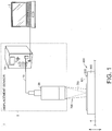
- FIG. 1 is a diagram showing a configuration of a measurement system according to the present embodiment.
- a measurement system 1 includes a displacement sensor 2, an information processing device 3, and a stage 4.
- the information processing device 3 is a personal computer.
- the displacement sensor 2 is a displacement measurement device using a white confocal method as a measurement method.
- the displacement sensor 2 is also called a fiber coaxial displacement sensor.
- the displacement sensor 2 includes a sensor controller 10, a light guiding unit 19, and a sensor head 20.
- the sensor head 20 includes a confocal optical system. Specifically, the sensor head 20 includes an objective lens and a chromatic aberration unit.
- the sensor controller 10 generates a light beam having a predetermined wavelength spread (wavelength width). Typically, the sensor controller 10 generates a white light beam. This light beam propagates through the light guiding unit 19 and reaches the sensor head 20.
- the propagated light beam is focused by the objective lens and is emitted to a measurement target object 800. Since axial chromatic aberration occurs in an emission light beam 700 passing through the chromatic aberration unit, focus positions of emission light beams emitted from the objective lens differ for each wavelength. Only a light beam with a wavelength at which a focus is formed on the measurement target object 800 reenters the light guiding unit 19.
- the stage 4 is movable in a direction (a vertical direction indicated by an arrow) on an optical axis of the emission light beam 700.
- the sensor controller 10 controls movement of the stage 4.
- the measurement target object 800 is mounted on the stage 4.
- the measurement target object 800 includes a substrate (base) 810 and a thin film 820 formed on the substrate 810.
- a front surface 821 is a surface that is exposed to the outside.
- a light beam 701 with a wavelength at which a focus is formed on the front surface 821 is received by the sensor head 20 as a reflected light beam.
- the reflected light beam received by the sensor head 20 enters the sensor controller 10 through the light guiding unit 19.
- the sensor controller 10 calculates a distance (displacement) from the sensor head 20 to the front surface 821 on the basis of the reflected light beam.
- the information processing device 3 is connected to the sensor controller 10.
- the information processing device 3 can change various settings of the sensor controller 10.
- information such as a distance calculated by the sensor controller 10 can be displayed.
- Various functions of the information processing device 3 will be described below. Here, such settings and display are possible in the single sensor controller 10.
- the displacement sensor 2 measures a distance between the sensor head 20 and the front surface 821 of the thin film 820, the detected wavelength deviates from a wavelength at which a focus is formed on the front surface 821 of the thin film 820 due to interference by the thin film 820. Therefore, it is necessary to correct a measured value. Details of correction will be described below.
- the displacement sensor 2 generates a function used when a plurality of measurement target objects 800 typically with the same lot (or the same type) are measured before such lots are measured (hereinafter also referred to as “during the present measurement") by preliminary measurement.
- the function is used to correct a measured value (distance).
- a measured value that can be measured by the displacement sensor 2 is used as a variable.
- the displacement sensor 2 generates the function using measured values measured at each of a plurality of positions when the stage 4 is moved to the plurality of positions.
- the displacement sensor 2 generates a plurality of continuous linear functions as the function.
- the displacement sensor 2 measures a distance to the front surface 821 which is a measurement target surface, and performs correction using a linear function corresponding to the measured value (distance). Specifically, the displacement sensor 2 corrects a measured value using a value of a linear function when the measured value is used as a value of a variable.
- stage position each position (a position in a vertical direction) of the stage 4 when the stage 4 is moved as indicated by an arrow in FIG. 1 will be referred to as a "stage position" for convenience of explanation.
- FIG. 2 is a diagram explaining data processing for generating a plurality of continuous linear functions.
- a horizontal axis (also referred to as an "X axis") of the graph represents a measured value M measured by the displacement sensor 2. That is, the horizontal axis represents a distance between the sensor head 20 and the front surface 821 of the thin film 820 measured by the displacement sensor 2.
- the value on the horizontal axis is a value obtained by performing offsetting on the measured value. Specifically, on the horizontal axis, a median value of the range of measured values obtained when the displacement sensor 2 measures the measurement target object 800 is set to 0.
- the vertical axis (also referred to as a "Y axis") of the graph represents a linearity error E.
- the "ideal value R” refers to a value set by a user and refers to a value indicating an ideal distance (reference distance) from the sensor head 20 to the front surface 821 of the thin film 820.
- the ideal value R is a value calculated from the stage position.
- the user measures a distance between the sensor head 20 and the front surface 821 of the thin film 820 at a plurality of stage positions by moving the stage 4 a plurality of times. For example, in order to obtain seven points P1 to P7 as shown in FIG. 2 , the user performs measurement seven times using the displacement sensor 2.
- an X coordinate of a point Pi (i is a natural number of 1 to 7) will be represented as "Mi” and a Y coordinate thereof will be represented as “Ei.”
- the point Pi is also represented as a "coordinate value Pi(Mi, Ei).”
- the ideal value R at the stage position at which the measured value Mi is obtained is referred to as an "ideal value Ri.”
- the displacement sensor 2 calculates a linearity error Ei obtained by subtracting the ideal value Ri from the measured value Mi using the measured values Mi obtained during seven measurements. Therefore, the displacement sensor 2 obtains seven coordinate values Pi(Mi, Ei).
- FIG. 3 is a diagram explaining the generated linear function.
- the dashed line graph shows experiment data as a comparative example.
- the dashed line graph shows data obtained when the stage 4 is continuously moved.
- a measurement process that is, during the present measurement
- seven points Pi which indicate discrete data items are used to perform correction in place of such continuous data items.
- the displacement sensor 2 In order to perform linear interpolation, the displacement sensor 2 generates six linear functions Fi(x) using seven coordinate values Pi(Mi, Ei). Specifically, two coordinate values whose X coordinates are adjacent to each other among the seven coordinate values Pi(Mi, Ei) are connected by a straight line and thus six continuous linear functions F1(X) to F6(X) are generated. For example, the displacement sensor 2 generates a linear function F1(X) using a coordinate value P1(M1, E1) and a coordinate value P2(M2, E2).
- the measured value M obtained during the present measurement is assigned as a value of a variable X.
- A indicates a slope of a line segment connecting two coordinate values whose X coordinates are adjacent to each other.
- F1(X) to F6(X) are specifically represented as follows.
- F 1 X E 2 ⁇ E 1 / M 2 ⁇ M 1 ⁇ X + E 1
- F 2 X E 3 ⁇ E 2 / M 3 ⁇ M 2 ⁇ X + E 2
- F 3 X E 4 ⁇ E 3 / M 4 ⁇ M 3 ⁇ X + E 3
- the displacement sensor 2 corrects the measured value using the linear functions F1(X) to F6(X) during the present measurement.
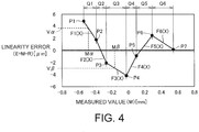
- FIG. 4 is a diagram explaining correction of the measured value.
- the displacement sensor 2 corrects the measured value M using the linear function Fi(x).
- the displacement sensor 2 performs correction using the following Formula (3) and thus obtains the corrected measured value C.
- C M ⁇ Fi x
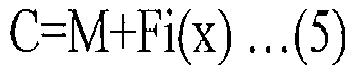
- the displacement sensor 2 may correct the measured value by using the following Formula (4) in place of the above Formula (2) and the following Formula (5) in place of the above Formula (3).
- the displacement sensor 2 performs the above correction on measured values (distances) obtained when measurement target surfaces of a plurality of measurement target objects 800 with the same lot are measured.
- the displacement sensor 2 it is possible to measure a distance from the front surface of the thin film which is a measurement target surface with high accuracy.
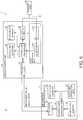
- FIG. 5 is a diagram explaining a functional configuration of the measurement system 1.
- the measurement system 1 includes the displacement sensor 2 and the information processing device 3.
- the displacement sensor 2 includes the sensor controller 10, the light guiding unit 19, and the sensor head 20.
- the sensor controller 10 includes a control unit 11, a light projecting unit 12, a light reception unit 13, a display unit 14, a communication interface (IF) unit 15, and a storage unit 16.
- the light reception unit 13 includes a spectroscope 131 and a detector 132.
- An emission light beam with a predetermined wavelength width generated by the light projecting unit 12 propagates through the light guiding unit 19 and reaches the sensor head 20.
- a reflected light beam that enters the sensor head 20 again propagates through the light guiding unit 19 and enters the light reception unit 13.
- the reflected light beam that has entered the spectroscope 131 is separated into wavelength components, and the detector 132 detects an intensity of each wavelength component.
- the control unit 11 calculates a distance (displacement) from the sensor head 20 to a measurement target surface of the measurement target object 800 (for example, the front surface 821 of the thin film 820) on the basis of the detection result of the detector 132.
- the control unit 11 generates the linear function Fi(x) and stores it in the storage unit 16.
- the control unit 11 appropriately reads the linear function Fi(x) and corrects the measured value using the linear function.
- the display unit 14 displays the distance calculated by the control unit 11 as a numerical value.
- a light receiving element configured to receive a reflected light beam differs according to a shape of a front surface of the measurement target object 800 with respect to the sensor head 20. Therefore, based on the detection result (pixel information) obtained by the plurality of light receiving elements of the detector 132, it is possible to measure a change in distance (displacement) with respect to the measurement target surface of the measurement target object 800. Therefore, a shape of the measurement target surface of the measurement target object 800 can be measured by the displacement sensor 2.
- the communication IF unit 15 is used for communication with the information processing device 3.
- the information processing device 3 includes a control unit 31, a storage unit 32, an input unit 33, a display unit 34, and a communication IF unit 35.
- the control unit 31 controls an operation of the information processing device 3.
- the control unit 31 executes a predetermined application program in an operating system stored in the storage unit 32.
- An example of a screen (user interface) displayed on the display unit 34 when the application program is executed will be described below.
- the control unit 31 receives a user input (input operation) through the input unit 33. In addition, the control unit 31 outputs a screen to the display unit 34. The control unit 31 performs communication with the sensor controller 10 through the communication IF unit 35.
- the information processing device 3 receives inputs of a predetermined number of (seven in the example in FIG. 2 ) of the measured values M and the ideal values R when the measured values M are obtained based on a user operation on the input unit 33.
- the information processing device 3 displays a screen (refer to FIG. 6 ) for receiving inputs of such values on the display unit 34.
- the information processing device 3 transmits sets of a plurality of received values (a set of the measured value M and the ideal value R) to the sensor controller 10.
- the information processing device 3 transmits seven sets of data in the case of FIG. 2 .
- the control unit 11 of the sensor controller 10 generates a plurality of linear functions Fi(X) used for correction based on sets of a plurality of values (a set of the measured value and the ideal value) received from the information processing device 3.
- the control unit 11 corrects the measured values (distances) using the generated linear function Fi(X) for the measurement target objects with the same lot during the measurement.
- the number of sets of data items (the measured value and the ideal value) input to the information processing device 3 by the user is not limited to seven. Such a number can be arbitrarily determined by the user.
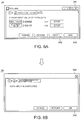
- FIG. 6(A) and FIG. 6(B) show diagrams of a screen example displayed on the display unit 34 of the information processing device 3.
- the control unit 31 of the information processing device 3 displays a screen 341 for inputting the measured value (a distance calculated by the displacement sensor 2) and the ideal value at each stage position.
- the control unit 31 displays the screen 341 superimposed on a base screen.
- the screen transitions to a screen as shown in a state of FIG. 6(B) and input of plurality of data items for correction ends.
- FIG. 7 is a sequence diagram explaining a flow of processes in the measurement system 1.
- the information processing device 3 repeatedly receives inputs of the measured value and the ideal value N times. For example, in the case of FIG. 2 , seven inputs are received.
- the information processing device 3 transmits N measured values M and N ideal values R to the displacement sensor 2. That is, the information processing device 3 transmits N sets of data items to the displacement sensor 2.
- the displacement sensor 2 In a sequence SQ6, the displacement sensor 2 generates N-1 linear functions Fi(X) based on the N measured values M and the N ideal values R.
- FIG. 8 is a flowchart explaining details of a process in the sequence SQ6 in FIG. 7 .
- Step S 12 the control unit 11 of the displacement sensor 2 sets a value of a variable i to 1.
- Step S14 the control unit 11 generates the linear function Fi(X) in an i-th section Qi (refer to FIG. 4 ) by using a measured value and an ideal value input in i-th place and a measured value M and an ideal value R input in (i+1)-th place in the information processing device 3.
- Step S16 the control unit 11 increments i. That is, the control unit 11 increases a value of i by 1.
- the control unit 11 determines whether i is equal to or larger than N.
- N indicates the number of sets of data items received by the displacement sensor 2 from the information processing device 3.
- Step S18 When it is determined that i is equal to or larger than N (YES in Step S18), the control unit 11 ends a series of processes. When it is determined that i is less than N (NO in Step S18), the control unit 11 advances the process to Step S 14.
- FIG. 9 is a flowchart explaining a process of correcting the measured value M during the present measurement.
- Step S102 the control unit 11 of the displacement sensor 2 acquires the measured value M. That is, the control unit 11 calculates a distance to the measurement target surface (the front surface 821 of the thin film 820) based on a light beam received by the sensor head 20.
- Step S104 the control unit 11 designates a linear function Fi(X) corresponding to the measured value M. That is, the control unit 11 designates a linear function Fi(X) in a section Qi in which the measured value M is included among the plurality of linear functions Fi(X).
- Step S106 the control unit 11 corrects the measured value M using the designated linear function Fi(X).
- Step S108 the control unit 11 outputs the corrected measured value (a measured value C).
- the control unit 11 displays the corrected measured value on the display unit 14.
- the control unit 11 stores the corrected measured value in the storage unit 16 (not shown).
- Step S110 the control unit 11 determines whether the measurement target object 800 with the same lot remains. When it is determined that the measurement target object 800 with the same lot remains (YES in Step S110), the control unit 11 advances the process to Step S102. When it is determined that no measurement target object 800 with the same lot remains (NO in Step S110), the control unit 11 ends a series of processes.
- FIG. 10 is a diagram explaining a result of an embodiment of the correction process described above.
- measured values are obtained while changing a stage position 50 times or more. Measurement is not generally performed such many times, but it is in this case in order to verify an effect.
- the vertical axis represents the linearity error E and the horizontal axis represents the measured value M measured by the displacement sensor 2.
- the dashed line graph is obtained by connecting points of 53 linearity errors E by line segments.
- these line segments themselves correspond to linear functions used for correction.
- the embodiments of the disclosure are not limited thereto.
- the generated function is not limited to the linear function.
- the generated function may be a quadratic function or a third or higher order function (high-order function).
- the generated function may be a second or higher order function that passes through seven points P1 to P7.
- a function may be generated using a least-square method.
- correction intervals that is, intervals between points
- correction intervals may not be the same interval.
- a configuration in which a white light beam is emitted to a measurement target object through a member by which wavelength dispersion occurs according to a refractive index will be described.
- a configuration in which a white light beam is emitted to a measurement target object through a glass will be described.
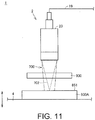
- FIG. 11 is a diagram explaining measurement in the present embodiment.
- the displacement sensor 2 measures a measurement target surface 851 of a measurement target object 800A.
- a light beam 702 with a wavelength at which a focus is formed on the measurement target surface 851 is received by the sensor head 20 as a reflected light beam.
- the reflected light beam received by the sensor head 20 enters the sensor controller 10 through the light guiding unit 19.
- the sensor controller 10 calculates a distance (displacement) from the sensor head 20 to the measurement target surface 851 on the basis of the reflected light beam.
- a distance to the measurement target surface 851 is calculated through a glass.
- the detected wavelength deviates from a wavelength at which a focus is formed on the measurement target surface 851 when it is assumed that there is no a glass. Therefore, in the present embodiment also, similarly to Embodiment 1, it is necessary to correct the measured value.
- a linear function Fi(X) for correction is generated by the displacement sensor 2 in advance.
- the control unit 11 of the displacement sensor 2 performs correction using the above Formula (3).
- Embodiment 2 similarly to Embodiment 2, a configuration in which a white light beam is emitted to a measurement target object through a member by which wavelength dispersion occurs according to a refractive index will be described. Specifically, a configuration in which the thickness of the transparent member (typically, a glass) is measured will be described.
- a transparent member typically, a glass
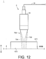
- FIG. 12 is a diagram explaining measurement in the present embodiment.
- the displacement sensor 2 measures a thickness of a glass 800B which is a measurement target object. Specifically, the displacement sensor 2 calculates a distance between the sensor head 20 and a front surface 871 of the glass 800B and a distance between the sensor head 20 and a back surface 872 of the glass 800B and thus calculates the thickness of the glass 800B.
- the "front surface” is a surface that is exposed to the outside, and is a surface on the side of the sensor head 20 in this example.
- the "back surface” is a surface that is in contact with the stage 4 and is a surface that is further away from the sensor head 20 than the front surface.
- a light beam 703 with a wavelength at which a focus is formed on the front surface 871 is received by the sensor head 20 as a reflected light beam.
- the reflected light beam received by the sensor head 20 enters the sensor controller 10 through the light guiding unit 19.
- the sensor controller 10 calculates a distance (displacement) from the sensor head 20 to the front surface 871 on the basis of the reflected light beam.
- a light beam 704 with a wavelength at which a focus is formed on the back surface 872 is received by the sensor head 20 as a reflected light beam.
- the reflected light beam received by the sensor head 20 enters the sensor controller 10 through the light guiding unit 19.
- the sensor controller 10 calculates a distance (displacement) from the sensor head 20 to the back surface 872 on the basis of the reflected light beam.
- the detected wavelength deviates due to wavelength dispersion causing by the glass 800B itself similarly to Embodiment 2. Therefore, in the present embodiment also, similarly to Embodiments 1 and 2, it is necessary to correct the measured value M.
- a linear function Fi(X) for correction is generated by the displacement sensor 2 in advance.
- the control unit 11 of the displacement sensor 2 performs correction using the above Formula (3).
- a method of setting the ideal value R for generating the linear function Fi(X) is different from those in Embodiments 1 and 2.
- the ideal value R is a value calculated from the stage position.
- a value obtained by adding an ideal thickness of the glass 800B to the measured value (distance) up to the front surface 871 is set as the ideal value R.
- the method of calculating the ideal value R in Embodiment 3 is different from the method of calculating the ideal value R in Embodiments 1 and 2.
- the reason for this is as follows.
- the thickness of the transparent member is measured, if the above correction is performed, it is possible to correct a nonlinear error due to wavelength dispersion of the glass 800B itself that is a measurement target object. Therefore, according to the displacement sensor 2, it is possible to measure the thickness (specifically, a distance to the back surface) of the transparent member with high accuracy.
Landscapes
- Physics & Mathematics (AREA)
- General Physics & Mathematics (AREA)
- Engineering & Computer Science (AREA)
- Computer Networks & Wireless Communication (AREA)
- Radar, Positioning & Navigation (AREA)
- Remote Sensing (AREA)
- Electromagnetism (AREA)
- Length Measuring Devices By Optical Means (AREA)
- Measurement Of Optical Distance (AREA)
Abstract
Description
- The disclosure relates to a displacement measurement device, a measurement system, and a displacement measurement method.
- In the related art, for example, as described in
Patent Document 1, a displacement measurement device using a white confocal method as a measurement method is known. According to such a displacement measurement device, it is possible to measure a distance to a measurement target object (specifically, a measurement target surface) based on a wavelength of a received light beam. - [Patent Document 1] Japanese Laid-open No.
2012-208102 - In a general displacement measurement device, when correction is performed with a reference workpiece during production, linearity between a distance and a measured value is secured. However, since correction in a production process is performed based on a reference workpiece, when a user uses a displacement measurement device in a production process, the relationship between a distance and a measured value may be nonlinear depending on workpieces.
- Such an error is a nonlinear error. Therefore, it is difficult to reduce the error in a method of correcting the entire measurement range using one linear function.
- For example, in measurement by a displacement measurement device using a white confocal method, errors occur as follows. When a measurement target surface is a front surface of a thin film formed on a substrate, due to interference caused by the thin film, the detected wavelength deviates from a wavelength at which a focus is formed on the front surface of the thin film.
- In addition, when a distance to a measurement target surface of a measurement target object is measured through a transparent member such as a glass, a refractive index by which wavelength dispersion occurs makes the relationship between a distance and a detection wavelength differs.
- Moreover, even when a distance to a front surface of the transparent member such as a glass and a distance to a back surface thereof are measured so as to measure a thickness of the transparent member, regarding measurement of the distance to the back surface, a refractive index by which wavelength dispersion occurs makes the relationship between the distance and a detection wavelength differs.
- The embodiments of the disclosure has been made in view of the above problems, and an object of the present disclosure is to provide a displacement measurement device and a measurement method through which it is possible to measure a distance to a measurement target surface with high accuracy.
- According to an embodiment of the disclosure, there is provided a displacement measurement device that includes a light projecting unit configured to generate a light beam; a sensor head configured to emit the light beam to a measurement target object of which a measured value and an actual displacement are nonlinear so that a focus is formed on a measurement target surface of the measurement target object and receive a light beam that is reflected at the measurement target surface within the emitted light beam; a storage unit configured to store a function using a distance between the sensor head and the measurement target surface as a variable; and a control unit configured to calculate the distance based on a wavelength of the light beam received by the sensor head. The control unit calculates a value of the function by using a first distance between the sensor head and a measurement target surface of a first measurement target object which is the measurement target object as a value of the variable. The control unit corrects the calculated first distance using the calculated value of the function.
- According to another embodiment of the disclosure, there is provided a displacement measurement device that includes a light projecting unit configured to generate a light beam having a predetermined wavelength width; a sensor head configured to emit the light beam through a member by which wavelength dispersion occurs according to a refractive index so that a focus is formed on a measurement target surface of a measurement target object and receive a light beam that is reflected at the measurement target surface within the emitted light beam; a storage unit configured to store a function using a distance between the sensor head and the measurement target surface as a variable; and a control unit configured to calculate the distance based on a wavelength of the light beam received by the sensor head. The control unit calculates a value of the function by using a first distance between the sensor head and a measurement target surface of a first measurement target object which is the measurement target object as a value of the variable. The control unit corrects the calculated first distance using the calculated value of the function.
- According to another embodiment of the disclosure, there is provided a measurement system that includes a displacement measurement device and an information processing device that is communicatively connected to the displacement measurement device. The information processing device receives a user operation by which the second distance that is calculated at each of the plurality of positions and the reference distance is inputted to the information processing device, and transmits the second distance that is calculated at each of the plurality of positions and the reference distance to the displacement measurement device.
- According to another embodiment of the disclosure, there is provided displacement measurement method includes: a step of generating a light beam; a step of emitting the light beam to a measurement target object of which a measured value and an actual displacement are nonlinear from a sensor head so that a focus is formed on a measurement target surface of the measurement target object; a step of receiving a light beam that is reflected at the measurement target surface within the emitted light beam; a step of calculating a distance between the sensor head and the measurement target surface based on a wavelength of the received light beam; a step of calculating a value of a function by serving the calculated distance as a value of a variable in the function using the distance as the variable; and a step of correcting the calculated distance using the calculated value of the function.
- According to another embodiment of the disclosure, there is provided displacement measurement method includes: a step of generating a light beam having a predetermined wavelength width; a step of emitting the light beam from a sensor head through a member by which wavelength dispersion occurs according to a refractive index so that a focus is formed on a measurement target surface of a measurement target object; a step of receiving a light beam that is reflected at the measurement target surface within the emitted light beam; a step of calculating a distance between the sensor head and the measurement target surface based on a wavelength of the received light beam; a step of calculating a value of a function by serving the calculated distance as a value of a variable in the function using the distance as the variable; and a step of correcting the calculated distance using the calculated value of the function.
- According to the present disclosure, it is possible to measure a distance to a measurement target surface with high accuracy.
-
-
FIG. 1 is a diagram showing a configuration of a measurement system according to the present embodiment. -
FIG. 2 is a diagram explaining data processing for generating a plurality of continuous linear functions. -
FIG. 3 is a diagram explaining a generated linear function. -
FIG. 4 is a diagram explaining correction of a measured value. -
FIG. 5 is a diagram explaining a functional configuration of a measurement system. -
FIG. 6(A) and FIG. 6(B) show diagrams of a screen example displayed on a display unit of an information processing device. -
FIG. 7 is a sequence diagram explaining a flow of processes in a measurement system. -
FIG. 8 is a flowchart explaining details of a process in a sequence SQ6 inFIG. 7 . -
FIG. 9 is a flowchart explaining a process of correcting a measured value during the present measurement. -
FIG. 10 is a diagram explaining a result of the correction process described above. -
FIG. 11 is a diagram explaining another form of measurement. -
FIG. 12 is a diagram explaining still another form of measurement. - Embodiments of the disclosure will be described below with reference to the drawings. In the following description, the same components are denoted with the same reference numerals. Their names and functions are also the same. Therefore, detailed description thereof will not be repeated.
- In
Embodiment 1, a case in which an error occurs due to interference will be described. InEmbodiments - Specifically, in
Embodiments Embodiment 1, a case in which a measurement target object causes interference will be exemplified. In addition, inEmbodiment 3, a case in which wavelength dispersion occurs according to a refractive index in a measurement target object will be exemplified. - In
Embodiment 2, a case in which a measurement target object is measured through a member by which wavelength dispersion occurs according to a refractive index will be described. - In addition, in the following embodiments, an example in which measurement is performed using a white confocal method will be exemplified. However, the measurement method is not limited thereto.
-
FIG. 1 is a diagram showing a configuration of a measurement system according to the present embodiment. - Referring to
FIG. 1 , ameasurement system 1 includes adisplacement sensor 2, aninformation processing device 3, and astage 4. Typically, theinformation processing device 3 is a personal computer. - The
displacement sensor 2 is a displacement measurement device using a white confocal method as a measurement method. Thedisplacement sensor 2 is also called a fiber coaxial displacement sensor. Thedisplacement sensor 2 includes asensor controller 10, alight guiding unit 19, and asensor head 20. Thesensor head 20 includes a confocal optical system. Specifically, thesensor head 20 includes an objective lens and a chromatic aberration unit. - The
sensor controller 10 generates a light beam having a predetermined wavelength spread (wavelength width). Typically, thesensor controller 10 generates a white light beam. This light beam propagates through thelight guiding unit 19 and reaches thesensor head 20. - In the
sensor head 20, the propagated light beam is focused by the objective lens and is emitted to ameasurement target object 800. Since axial chromatic aberration occurs in anemission light beam 700 passing through the chromatic aberration unit, focus positions of emission light beams emitted from the objective lens differ for each wavelength. Only a light beam with a wavelength at which a focus is formed on themeasurement target object 800 reenters thelight guiding unit 19. - The
stage 4 is movable in a direction (a vertical direction indicated by an arrow) on an optical axis of theemission light beam 700. Thesensor controller 10 controls movement of thestage 4. Themeasurement target object 800 is mounted on thestage 4. - The
measurement target object 800 includes a substrate (base) 810 and athin film 820 formed on thesubstrate 810. Here, afront surface 821 is a surface that is exposed to the outside. - A
light beam 701 with a wavelength at which a focus is formed on thefront surface 821 is received by thesensor head 20 as a reflected light beam. The reflected light beam received by thesensor head 20 enters thesensor controller 10 through thelight guiding unit 19. Thesensor controller 10 calculates a distance (displacement) from thesensor head 20 to thefront surface 821 on the basis of the reflected light beam. - The
information processing device 3 is connected to thesensor controller 10. Theinformation processing device 3 can change various settings of thesensor controller 10. In addition, in theinformation processing device 3, information such as a distance calculated by thesensor controller 10 can be displayed. Various functions of theinformation processing device 3 will be described below. Here, such settings and display are possible in thesingle sensor controller 10. - Here, since hardware configurations of the
sensor controller 10, thesensor head 20, and thelight guiding unit 19 are the same as those in the related art, descriptions thereof will not be repeated here. - Since the
displacement sensor 2 measures a distance between thesensor head 20 and thefront surface 821 of thethin film 820, the detected wavelength deviates from a wavelength at which a focus is formed on thefront surface 821 of thethin film 820 due to interference by thethin film 820. Therefore, it is necessary to correct a measured value. Details of correction will be described below. - The
displacement sensor 2 generates a function used when a plurality of measurement target objects 800 typically with the same lot (or the same type) are measured before such lots are measured (hereinafter also referred to as "during the present measurement") by preliminary measurement. The function is used to correct a measured value (distance). In the function, a measured value that can be measured by thedisplacement sensor 2 is used as a variable. - In addition, the
displacement sensor 2 generates the function using measured values measured at each of a plurality of positions when thestage 4 is moved to the plurality of positions. Typically, thedisplacement sensor 2 generates a plurality of continuous linear functions as the function. - The
displacement sensor 2 measures a distance to thefront surface 821 which is a measurement target surface, and performs correction using a linear function corresponding to the measured value (distance). Specifically, thedisplacement sensor 2 corrects a measured value using a value of a linear function when the measured value is used as a value of a variable. - Details of such processes will be described below with reference to a specific example. Hereinafter, each position (a position in a vertical direction) of the
stage 4 when thestage 4 is moved as indicated by an arrow inFIG. 1 will be referred to as a "stage position" for convenience of explanation. -
FIG. 2 is a diagram explaining data processing for generating a plurality of continuous linear functions. - Referring to
FIG. 2 , a horizontal axis (also referred to as an "X axis") of the graph represents a measured value M measured by thedisplacement sensor 2. That is, the horizontal axis represents a distance between thesensor head 20 and thefront surface 821 of thethin film 820 measured by thedisplacement sensor 2. Here, the value on the horizontal axis is a value obtained by performing offsetting on the measured value. Specifically, on the horizontal axis, a median value of the range of measured values obtained when thedisplacement sensor 2 measures themeasurement target object 800 is set to 0. - The vertical axis (also referred to as a "Y axis") of the graph represents a linearity error E. Specifically, the vertical axis represents a value (E=M-R) obtained by subtracting an ideal value R from the measured value M. Here, the "ideal value R" refers to a value set by a user and refers to a value indicating an ideal distance (reference distance) from the
sensor head 20 to thefront surface 821 of thethin film 820. The ideal value R is a value calculated from the stage position. - The user measures a distance between the
sensor head 20 and thefront surface 821 of thethin film 820 at a plurality of stage positions by moving the stage 4 a plurality of times. For example, in order to obtain seven points P1 to P7 as shown inFIG. 2 , the user performs measurement seven times using thedisplacement sensor 2. - Hereinafter, for convenience of explanation, an X coordinate of a point Pi (i is a natural number of 1 to 7) will be represented as "Mi" and a Y coordinate thereof will be represented as "Ei." In addition, the point Pi is also represented as a "coordinate value Pi(Mi, Ei)." In addition, the ideal value R at the stage position at which the measured value Mi is obtained is referred to as an "ideal value Ri."
- Specifically, the
displacement sensor 2 calculates a linearity error Ei obtained by subtracting the ideal value Ri from the measured value Mi using the measured values Mi obtained during seven measurements. Therefore, thedisplacement sensor 2 obtains seven coordinate values Pi(Mi, Ei). -
FIG. 3 is a diagram explaining the generated linear function. - Referring to
FIG. 3 , the dashed line graph shows experiment data as a comparative example. The dashed line graph shows data obtained when thestage 4 is continuously moved. In thedisplacement sensor 2, in a measurement process (that is, during the present measurement) such as product examination, in order to speed up the process, seven points Pi which indicate discrete data items are used to perform correction in place of such continuous data items. - In order to perform linear interpolation, the
displacement sensor 2 generates six linear functions Fi(x) using seven coordinate values Pi(Mi, Ei). Specifically, two coordinate values whose X coordinates are adjacent to each other among the seven coordinate values Pi(Mi, Ei) are connected by a straight line and thus six continuous linear functions F1(X) to F6(X) are generated. For example, thedisplacement sensor 2 generates a linear function F1(X) using a coordinate value P1(M1, E1) and a coordinate value P2(M2, E2). - Each linear function Fi(x) is represented by the following Formula (1).

- Here, in Formula (1), the measured value M obtained during the present measurement is assigned as a value of a variable X.
- In Formula (1), "A" indicates a slope of a line segment connecting two coordinate values whose X coordinates are adjacent to each other. In Formula (1), "B" indicates a value of the linearity error Ei (=Ri-Mi) at an end point on the left side of each line segment.
- The linear functions F1(X) to F6(X) are specifically represented as follows.


- When these six linear functions are generalized using i, Formula (2) is obtained.

- In generalization using i, when the measured value M is a value included in a range of Mi to M(i+1), the linear function Fi(x) is used.
- As described above, the
displacement sensor 2 corrects the measured value using the linear functions F1(X) to F6(X) during the present measurement. -
FIG. 4 is a diagram explaining correction of the measured value. - Referring to
FIG. 4 , when the calculated measured value M (distance, value of the variable X) is a value included in a section Qi (Mi<M<M(i+1)) in an X axis direction, thedisplacement sensor 2 corrects the measured value M using the linear function Fi(x). - Specifically, the
displacement sensor 2 performs correction using the following Formula (3) and thus obtains the corrected measured value C.
- For example, when a value Mα in a section Q1 shown in the drawing is obtained as the measured value M, the
displacement sensor 2 subtracts a value Vα (=F1(Mα)) of a function when a value of X of the function F1(X) is set as Mα from Mα, and thus the corrected measured value C is obtained. - In addition, when a value Mβ in a section Q3 shown in the drawing is obtained as the measured value M, the
displacement sensor 2 subtracts a value Vβ (=F3(Mβ)) of a function when a value of X of the function F3(X) is set as Mβ from Mβ, and thus the corrected measured value C is obtained. - Here, the
displacement sensor 2 may correct the measured value by using the following Formula (4) in place of the above Formula (2) and the following Formula (5) in place of the above Formula (3).
- In the same manner, the
displacement sensor 2 performs the above correction on measured values (distances) obtained when measurement target surfaces of a plurality of measurement target objects 800 with the same lot are measured. - When such correction is performed, a nonlinear error due to interference can be corrected. Therefore, according to the
displacement sensor 2, it is possible to measure a distance from the front surface of the thin film which is a measurement target surface with high accuracy. -
FIG. 5 is a diagram explaining a functional configuration of themeasurement system 1. - Referring to
FIG. 5 , as described above, themeasurement system 1 includes thedisplacement sensor 2 and theinformation processing device 3. Thedisplacement sensor 2 includes thesensor controller 10, thelight guiding unit 19, and thesensor head 20. - The
sensor controller 10 includes acontrol unit 11, alight projecting unit 12, alight reception unit 13, adisplay unit 14, a communication interface (IF)unit 15, and astorage unit 16. Thelight reception unit 13 includes aspectroscope 131 and adetector 132. - An emission light beam with a predetermined wavelength width generated by the
light projecting unit 12 propagates through thelight guiding unit 19 and reaches thesensor head 20. A reflected light beam that enters thesensor head 20 again propagates through thelight guiding unit 19 and enters thelight reception unit 13. In thelight reception unit 13, the reflected light beam that has entered thespectroscope 131 is separated into wavelength components, and thedetector 132 detects an intensity of each wavelength component. - The
control unit 11 calculates a distance (displacement) from thesensor head 20 to a measurement target surface of the measurement target object 800 (for example, thefront surface 821 of the thin film 820) on the basis of the detection result of thedetector 132. Thecontrol unit 11 generates the linear function Fi(x) and stores it in thestorage unit 16. Thecontrol unit 11 appropriately reads the linear function Fi(x) and corrects the measured value using the linear function. - The
display unit 14 displays the distance calculated by thecontrol unit 11 as a numerical value. - Among a plurality of light receiving elements constituting the
detector 132 of thelight reception unit 13, a light receiving element configured to receive a reflected light beam differs according to a shape of a front surface of themeasurement target object 800 with respect to thesensor head 20. Therefore, based on the detection result (pixel information) obtained by the plurality of light receiving elements of thedetector 132, it is possible to measure a change in distance (displacement) with respect to the measurement target surface of themeasurement target object 800. Therefore, a shape of the measurement target surface of themeasurement target object 800 can be measured by thedisplacement sensor 2. - The communication IF
unit 15 is used for communication with theinformation processing device 3. - The
information processing device 3 includes acontrol unit 31, astorage unit 32, aninput unit 33, adisplay unit 34, and a communication IFunit 35. - The
control unit 31 controls an operation of theinformation processing device 3. Thecontrol unit 31 executes a predetermined application program in an operating system stored in thestorage unit 32. An example of a screen (user interface) displayed on thedisplay unit 34 when the application program is executed will be described below. - The
control unit 31 receives a user input (input operation) through theinput unit 33. In addition, thecontrol unit 31 outputs a screen to thedisplay unit 34. Thecontrol unit 31 performs communication with thesensor controller 10 through the communication IFunit 35. - The
information processing device 3 receives inputs of a predetermined number of (seven in the example inFIG. 2 ) of the measured values M and the ideal values R when the measured values M are obtained based on a user operation on theinput unit 33. Theinformation processing device 3 displays a screen (refer toFIG. 6 ) for receiving inputs of such values on thedisplay unit 34. - The
information processing device 3 transmits sets of a plurality of received values (a set of the measured value M and the ideal value R) to thesensor controller 10. Theinformation processing device 3 transmits seven sets of data in the case ofFIG. 2 . - The
control unit 11 of thesensor controller 10 generates a plurality of linear functions Fi(X) used for correction based on sets of a plurality of values (a set of the measured value and the ideal value) received from theinformation processing device 3. Thecontrol unit 11 corrects the measured values (distances) using the generated linear function Fi(X) for the measurement target objects with the same lot during the measurement. - Here, the number of sets of data items (the measured value and the ideal value) input to the
information processing device 3 by the user is not limited to seven. Such a number can be arbitrarily determined by the user. -
FIG. 6(A) and FIG. 6(B) show diagrams of a screen example displayed on thedisplay unit 34 of theinformation processing device 3. - Referring to
FIG. 6(A) and FIG. 6(B) , thecontrol unit 31 of theinformation processing device 3 displays ascreen 341 for inputting the measured value (a distance calculated by the displacement sensor 2) and the ideal value at each stage position. Typically, thecontrol unit 31 displays thescreen 341 superimposed on a base screen. - In a state of
FIG. 6(A) , a state in which fifth data (the measured value and the ideal value) is input based on a user operation. In order to input sixth data, the user selects anobject 342. Therefore, thecontrol unit 31 of theinformation processing device 3 displays a screen for inputting sixth data. - When the user determines that five data items are sufficient, he or she may select an
object 343 indicating end. Therefore, the screen transitions to a screen as shown in a state ofFIG. 6(B) and input of plurality of data items for correction ends. - When the user selects an
object 349 indicating end, a set of input data items is transmitted to thesensor controller 10 of thedisplacement sensor 2. Therefore, the linear function Fi(X) is generated in thesensor controller 10. - First, generation of a linear function Fi(X) used for correction will be described with reference to
FIG. 7 andFIG. 8 . A process of correcting a measured value using the generated linear function Fi(X) during the present measurement will be described with reference toFIG. 9 . -
FIG. 7 is a sequence diagram explaining a flow of processes in themeasurement system 1. - Referring to
FIG. 7 , in a sequence SQ2, theinformation processing device 3 repeatedly receives inputs of the measured value and the ideal value N times. For example, in the case ofFIG. 2 , seven inputs are received. - In a sequence SQ4, the
information processing device 3 transmits N measured values M and N ideal values R to thedisplacement sensor 2. That is, theinformation processing device 3 transmits N sets of data items to thedisplacement sensor 2. - In a sequence SQ6, the
displacement sensor 2 generates N-1 linear functions Fi(X) based on the N measured values M and the N ideal values R. -
FIG. 8 is a flowchart explaining details of a process in the sequence SQ6 inFIG. 7 . - Referring to
FIG. 8 , inStep S 12, thecontrol unit 11 of thedisplacement sensor 2 sets a value of a variable i to 1. In Step S14, thecontrol unit 11 generates the linear function Fi(X) in an i-th section Qi (refer toFIG. 4 ) by using a measured value and an ideal value input in i-th place and a measured value M and an ideal value R input in (i+1)-th place in theinformation processing device 3. - In Step S16, the
control unit 11 increments i. That is, thecontrol unit 11 increases a value of i by 1. In Step 518, thecontrol unit 11 determines whether i is equal to or larger than N. Here, N indicates the number of sets of data items received by thedisplacement sensor 2 from theinformation processing device 3. - When it is determined that i is equal to or larger than N (YES in Step S18), the
control unit 11 ends a series of processes. When it is determined that i is less than N (NO in Step S18), thecontrol unit 11 advances the process to StepS 14. -
FIG. 9 is a flowchart explaining a process of correcting the measured value M during the present measurement. - Referring to
FIG. 9 , in Step S102, thecontrol unit 11 of thedisplacement sensor 2 acquires the measured value M. That is, thecontrol unit 11 calculates a distance to the measurement target surface (thefront surface 821 of the thin film 820) based on a light beam received by thesensor head 20. - In Step S104, the
control unit 11 designates a linear function Fi(X) corresponding to the measured value M. That is, thecontrol unit 11 designates a linear function Fi(X) in a section Qi in which the measured value M is included among the plurality of linear functions Fi(X). - In Step S106, the
control unit 11 corrects the measured value M using the designated linear function Fi(X). In Step S108, thecontrol unit 11 outputs the corrected measured value (a measured value C). For example, thecontrol unit 11 displays the corrected measured value on thedisplay unit 14. In addition, thecontrol unit 11 stores the corrected measured value in the storage unit 16 (not shown). - In Step S110, the
control unit 11 determines whether themeasurement target object 800 with the same lot remains. When it is determined that themeasurement target object 800 with the same lot remains (YES in Step S110), thecontrol unit 11 advances the process to Step S102. When it is determined that nomeasurement target object 800 with the same lot remains (NO in Step S110), thecontrol unit 11 ends a series of processes. -
FIG. 10 is a diagram explaining a result of an embodiment of the correction process described above. - Referring to
FIG. 10 , for a certain measurement target object, measured values are obtained while changing a stage position 50 times or more. Measurement is not generally performed such many times, but it is in this case in order to verify an effect. Here, the vertical axis represents the linearity error E and the horizontal axis represents the measured value M measured by thedisplacement sensor 2. - The dashed line graph relates to the linearity error E (E=M-R) before correction. Specifically, the dashed line graph is obtained by connecting points of 53 linearity errors E by line segments. Here, these line segments themselves correspond to linear functions used for correction.
- The solid line graph relates to the linearity error E (E=M-R) before correction. Specifically, the solid line graph is obtained by connecting points of 53 corrected linearity errors E by line segments.
- Comparing the dashed line graph and the solid line graph, it can be understood that the linearity error E is reduced by correction.
- While a configuration in which the
sensor controller 10 generates the plurality of linear functions Fi(X) has been exemplified above, the embodiments of the disclosure are not limited thereto. The generated function is not limited to the linear function. - The generated function may be a quadratic function or a third or higher order function (high-order function). For example, in the example in
FIG. 2 , the generated function may be a second or higher order function that passes through seven points P1 to P7. - In addition, it is not necessary to generate a function that passes through points. For example, a function may be generated using a least-square method.
- In addition, correction intervals (that is, intervals between points) may not be the same interval.
- Such a modified example can be applied to
Embodiments - In the present embodiment, a configuration in which a white light beam is emitted to a measurement target object through a member by which wavelength dispersion occurs according to a refractive index will be described. Typically, a configuration in which a white light beam is emitted to a measurement target object through a glass will be described.
-
FIG. 11 is a diagram explaining measurement in the present embodiment. - Referring to
FIG. 11 , thedisplacement sensor 2 measures ameasurement target surface 851 of ameasurement target object 800A. - A
light beam 702 with a wavelength at which a focus is formed on themeasurement target surface 851 is received by thesensor head 20 as a reflected light beam. The reflected light beam received by thesensor head 20 enters thesensor controller 10 through thelight guiding unit 19. Thesensor controller 10 calculates a distance (displacement) from thesensor head 20 to themeasurement target surface 851 on the basis of the reflected light beam. - Incidentally, in measurement in the present embodiment, a distance to the
measurement target surface 851 is calculated through a glass. In this case, according to wavelength dispersion due to the glass, the detected wavelength deviates from a wavelength at which a focus is formed on themeasurement target surface 851 when it is assumed that there is no a glass. Therefore, in the present embodiment also, similarly toEmbodiment 1, it is necessary to correct the measured value. - Specifically, also in the present embodiment, similarly to
Embodiment 1, a linear function Fi(X) for correction is generated by thedisplacement sensor 2 in advance. Thus, during the measurement, using the linear function Fi(X) corresponding to the measured section Qi, the measured value is corrected. Specifically, thecontrol unit 11 of thedisplacement sensor 2 performs correction using the above Formula (3). - When measurement is performed through such a transparent member, the above correction is performed. Therefore, it is possible to correct a nonlinear error due to wavelength dispersion in the transparent member. Therefore, it is possible to measure a distance to the
measurement target surface 851 with high accuracy according to thedisplacement sensor 2. - In the present embodiment, similarly to
Embodiment 2, a configuration in which a white light beam is emitted to a measurement target object through a member by which wavelength dispersion occurs according to a refractive index will be described. Specifically, a configuration in which the thickness of the transparent member (typically, a glass) is measured will be described. -
FIG. 12 is a diagram explaining measurement in the present embodiment. - Referring to
FIG. 12 , thedisplacement sensor 2 measures a thickness of aglass 800B which is a measurement target object. Specifically, thedisplacement sensor 2 calculates a distance between thesensor head 20 and afront surface 871 of theglass 800B and a distance between thesensor head 20 and aback surface 872 of theglass 800B and thus calculates the thickness of theglass 800B. Here, the "front surface" is a surface that is exposed to the outside, and is a surface on the side of thesensor head 20 in this example. The "back surface" is a surface that is in contact with thestage 4 and is a surface that is further away from thesensor head 20 than the front surface. - More specifically, a
light beam 703 with a wavelength at which a focus is formed on thefront surface 871 is received by thesensor head 20 as a reflected light beam. The reflected light beam received by thesensor head 20 enters thesensor controller 10 through thelight guiding unit 19. Thesensor controller 10 calculates a distance (displacement) from thesensor head 20 to thefront surface 871 on the basis of the reflected light beam. - A
light beam 704 with a wavelength at which a focus is formed on theback surface 872 is received by thesensor head 20 as a reflected light beam. The reflected light beam received by thesensor head 20 enters thesensor controller 10 through thelight guiding unit 19. Thesensor controller 10 calculates a distance (displacement) from thesensor head 20 to theback surface 872 on the basis of the reflected light beam. - Incidentally, in measurement in the present embodiment, when a distance to the
back surface 872 is measured (calculated), the detected wavelength deviates due to wavelength dispersion causing by theglass 800B itself similarly toEmbodiment 2. Therefore, in the present embodiment also, similarly toEmbodiments - Specifically, also in the present embodiment, similarly to
Embodiment 1, a linear function Fi(X) for correction is generated by thedisplacement sensor 2 in advance. Thus, during the present measurement, using the linear function Fi(X) corresponding to the measured section Qi, the measured value is corrected. Specifically, thecontrol unit 11 of thedisplacement sensor 2 performs correction using the above Formula (3). - A method of setting the ideal value R for generating the linear function Fi(X) is different from those in
Embodiments Embodiments glass 800B to the measured value (distance) up to thefront surface 871 is set as the ideal value R. - In this manner, the method of calculating the ideal value R in
Embodiment 3 is different from the method of calculating the ideal value R inEmbodiments - In an embodiment, when only the
back surface 872 is corrected and the thickness of theglass 800B is calculated (when the measured value of thefront surface 871 is subtracted from the measured value of the back surface 872), an influence of a linearity error of thefront surface 871 is received and the error increases. When the ideal value is obtained from the measured value of thefront surface 871, the linearity error of thefront surface 871 can be corrected. As a result, the thickness error can be reduced. - As described above, when the thickness of the transparent member is measured, if the above correction is performed, it is possible to correct a nonlinear error due to wavelength dispersion of the
glass 800B itself that is a measurement target object. Therefore, according to thedisplacement sensor 2, it is possible to measure the thickness (specifically, a distance to the back surface) of the transparent member with high accuracy. -
- 1
- Measurement system
- 2
- Displacement sensor
- 3
- Information processing device
- 4
- Stage
- 10
- Sensor controller
- 11, 31
- Control unit
- 12
- Light projecting unit
- 13
- Light reception unit
- 14, 34
- Display unit
- 15, 35
- Communication IF unit
- 16, 32
- Storage unit
- 19
- Light guiding unit
- 20
- Sensor head
- 33
- Input unit
- 131
- Spectroscope
- 132
- Detector
- 341
- Screen
- 342, 343, 349
- Object
- 700
- Emission light beam
- 701, 702, 703, 704
- Light beam
- 800, 800A
- Measurement target object
- 800B
- Glass
- 810
- Substrate
- 820
- Thin film
- 821, 871
- Front surface
- 851
- Measurement target surface
- 872
- Back surface
Claims (11)
- A displacement measurement device (2) comprising:a light projecting unit (12) configured to generate a light beam (700);a sensor head (20) configured to emit the light beam (700) to a measurement target object (800, 800A, 800B) of which a measured value and an actual displacement are nonlinear so that a focus is formed on a measurement target surface (821, 851, 872) of the measurement target object (800, 800A, 800B), and receive a light beam (701, 702, 704) that is reflected at the measurement target surface (821, 851, 872) within the emitted light beam (700);a storage unit (16) configured to store a function using a distance between the sensor head (20) and the measurement target surface (821, 851, 872) as a variable; anda control unit (11) configured to calculate the distance based on a wavelength of the light beam (701, 702, 704) received by the sensor head (20),wherein the control unit (11) calculates a value of the function by using a first distance between the sensor head (20) and a measurement target surface (821, 851, 872) of a first measurement target object which is the measurement target object (800, 800A, 800B) as a value of the variable, and corrects the calculated first distance using the calculated value of the function.
- A displacement measurement device (2) comprising:a light projecting unit (12) configured to generate a light beam (700) having a predetermined wavelength width;a sensor head (20) configured to emit the light beam (700) through a member (800B, 900) by which wavelength dispersion occurs according to a refractive index so that a focus is formed on a measurement target surface (851, 872) of a measurement target object (800A, 800B), and receive a light beam (702, 704) that is reflected at the measurement target surface (851, 872) within the emitted light beam (700);a storage unit configured to store a function using a distance between the sensor head (20) and the measurement target surface (851, 872) as a variable; anda control unit (11) configured to calculate the distance based on a wavelength of the light beam (702, 704) received by the sensor head (20),wherein the control unit (11) calculates a value of the function by using a first distance between the sensor head (20) and a measurement target surface (851, 872) of a first measurement target object which is the measurement target object (800A, 800B) as a value of the variable, and corrects the calculated first distance using the calculated value of the function.
- The displacement measurement device (2) according to claim 1,
wherein the first measurement target object as the measurement target object and a second measurement target object (800) as the measurement target object have a thin film (820) causing interference, and
wherein the control unit (11) calculates a second distance that is a distance between the sensor head (20) and a front surface (821) of the thin film (820) by moving a stage (4) to a plurality of positions while the second measurement target object (800) is mounted on the stage (4) that is movable in a direction of the sensor head (20), and
generates the function on the basis of the second distance calculated at each of the plurality of positions and a reference distance that serves as a reference between the sensor head (20) and the front surface (821) when the second distance is calculated. - The displacement measurement device (2) according to claim 2,
wherein the control unit (11) calculates a second distance that is a distance between the sensor head (20) and a measurement target surface (851, 872) of a second measurement target object (800A, 800B) as the measurement target object by moving a stage (4) to a plurality of positions while the second measurement target object (800A, 800B) that is the measurement target object is mounted on the stage (4) that is movable in a direction of the sensor head (20), and
generates the function on the basis of the second distance calculated at each of the plurality of positions and a reference distance that serves as a reference between the sensor head (20) and the measurement target surface (851, 872) when the second distance is calculated. - The displacement measurement device (2) according to claim 1,
wherein the measurement target object (800B) is an object having a first surface (871) as the measurement target surface and a second surface (872) as the measurement target surface that is further away from the sensor head (20) than the first surface and causing wavelength dispersion,
wherein the control unit (11) calculates a second distance between the sensor head (20) and the measurement target surface (872) of a second measurement target object by moving a stage to a plurality of positions while the second measurement target object that is the measurement target object (800B) is mounted on the stage (4) that is movable in a direction of the sensor head (20), and
generates the function on the basis of the second distance calculated at each of the plurality of positions and a reference distance when the second distance is calculated, and
wherein the reference distance is a distance obtained by adding an ideal thickness of the measurement target object (800B) to a distance from the sensor head (20) to the first surface (871). - The displacement measurement device (2) according to any one of claims 3 to 5, wherein the control unit (11) generates the function based on the second distance and a difference between the second distance and the reference distance.
- The displacement measurement device (2) according to claim 6,
wherein the control unit (11) divides a numerical value range of the variable in a plurality of sections (Q1-Q6) using the second distance calculated at each of the plurality of positions, and
generates the function for each of the plurality of sections (Q1-Q6). - The displacement measurement device (2) according to claim 7, wherein the function of each of the sections (Q1-Q6) is a linear function.
- A measurement system (1) including the displacement measurement device (2) according to any one of claims 3 to 8, and an information processing device (3) that is communicatively connected to the displacement measurement device,
wherein the information processing device (3) receives a user operation by which the second distance that is calculated at each of the plurality of positions and the reference distance is inputted to the information processing device (3), and
transmits the second distance that is calculated at each of the plurality of positions and the reference distance to the displacement measurement device. - A displacement measurement method comprising:a step of generating a light beam (700);a step of emitting the light beam (700) to a measurement target object (800, 800A, 800B) of which a measured value and an actual displacement are nonlinear from a sensor head (20) so that a focus is formed on a measurement target surface (821, 851, 872) of the measurement target object (800, 800A, 800B);a step of receiving a light beam (701, 702, 704) that is reflected at the measurement target surface (821, 851, 872) within the emitted light beam (700);a step of calculating a distance between the sensor head (20) and the measurement target surface (821, 851, 872) based on a wavelength of the received light beam (701, 702, 704);a step (SQ6) of calculating a value of a function by serving the calculated distance as a value of a variable in the function using the distance as the variable; anda step (S106) of correcting the calculated distance using the calculated value of the function.
- A displacement measurement method comprising:a step of generating a light beam (700) having a predetermined wavelength width;a step of emitting the light beam (700) from a sensor head (20) through a member (800B, 900) by which wavelength dispersion occurs according to a refractive index so that a focus is formed on a measurement target surface (851, 872) of a measurement target object (800A, 800B);a step of receiving a light beam (702, 704) that is reflected at the measurement target surface (851, 872) within the emitted light beam (700);a step of calculating a distance between the sensor head (20) and the measurement target surface (851, 872) based on a wavelength of the received light beam (702, 704);a step (SQ6) of calculating a value of a function by serving the calculated distance as a value of a variable in the function using the distance as the variable; anda step (S106) of correcting the calculated distance using the calculated value of the function.
Applications Claiming Priority (1)
| Application Number | Priority Date | Filing Date | Title |
|---|---|---|---|
| JP2017185000A JP6919458B2 (en) | 2017-09-26 | 2017-09-26 | Displacement measuring device, measuring system, and displacement measuring method |
Publications (2)
| Publication Number | Publication Date |
|---|---|
| EP3460390A1 true EP3460390A1 (en) | 2019-03-27 |
| EP3460390B1 EP3460390B1 (en) | 2023-07-26 |
Family
ID=61189377
Family Applications (1)
| Application Number | Title | Priority Date | Filing Date |
|---|---|---|---|
| EP18156150.7A Active EP3460390B1 (en) | 2017-09-26 | 2018-02-09 | Displacement measurement device, measurement system, and displacement measurement method |
Country Status (6)
| Country | Link |
|---|---|
| US (1) | US10444360B2 (en) |
| EP (1) | EP3460390B1 (en) |
| JP (1) | JP6919458B2 (en) |
| KR (2) | KR20190035458A (en) |
| CN (1) | CN109556518B (en) |
| TW (1) | TWI658251B (en) |
Families Citing this family (3)
| Publication number | Priority date | Publication date | Assignee | Title |
|---|---|---|---|---|
| KR102823125B1 (en) * | 2020-06-30 | 2025-06-30 | 에베 그룹 에. 탈너 게엠베하 | Device and method for substrate alignment |
| JP7518782B2 (en) | 2021-02-19 | 2024-07-18 | キヤノン株式会社 | MEASUREMENT APPARATUS, LITHOGRAPHIC APPARATUS, AND METHOD FOR MANUFACTURING ARTICLE - Patent application |
| US11781420B2 (en) | 2021-03-25 | 2023-10-10 | Chengdu University Of Technology | Displacement measuring device and speed measuring method of drilling traction robot |
Citations (6)
| Publication number | Priority date | Publication date | Assignee | Title |
|---|---|---|---|---|
| JPH07120216A (en) * | 1993-10-25 | 1995-05-12 | Fanuc Ltd | Data correction method for optical displacement sensor |
| US20070148792A1 (en) * | 2005-12-27 | 2007-06-28 | Marx David S | Wafer measurement system and apparatus |
| EP2060869A1 (en) * | 2007-11-14 | 2009-05-20 | Mitutoyo Corporation | Dynamic Compensation Of Profile Data Selection for a Chromatic Point Sensor |
| EP2278268A2 (en) * | 2009-07-16 | 2011-01-26 | Mitutoyo Corporation | Optical displacement meter |
| JP2012208102A (en) | 2011-03-14 | 2012-10-25 | Omron Corp | Confocal measuring device |
| WO2017046254A1 (en) * | 2015-09-15 | 2017-03-23 | Carl Zeiss Industrielle Messtechnik Gmbh | Operating a confocal white light sensor on a coordinate measuring device |
Family Cites Families (34)
| Publication number | Priority date | Publication date | Assignee | Title |
|---|---|---|---|---|
| JPH0814484B2 (en) * | 1985-04-09 | 1996-02-14 | 株式会社ニコン | Pattern position measuring device |
| JPH063115A (en) * | 1992-06-19 | 1994-01-11 | Hitachi Ltd | Sample height measuring device |
| JPH06273166A (en) * | 1993-03-19 | 1994-09-30 | Keyence Corp | Compensation value acquisition device and compensation device for optical distance-measuring device |
| JP2603429B2 (en) * | 1993-10-25 | 1997-04-23 | 工業技術院長 | Tracking laser interferometer |
| JPH0979844A (en) * | 1995-09-14 | 1997-03-28 | Nippon Telegr & Teleph Corp <Ntt> | Calibration method of distance measuring sensor |
| JPH09178439A (en) * | 1995-12-27 | 1997-07-11 | Technol Res Assoc Of Medical & Welfare Apparatus | 3D shape measuring device |
| DE19713362A1 (en) * | 1997-03-29 | 1998-10-01 | Zeiss Carl Jena Gmbh | Confocal microscopic arrangement |
| US6630680B2 (en) * | 2000-12-25 | 2003-10-07 | Fuji Photo Film Co., Ltd. | Scanner having confocal optical system, method for producing focus position data of confocal optical system of scanner having confocal optical system and method for producing digital data of scanner having confocal optical system |
| IL146174A (en) * | 2001-10-25 | 2007-08-19 | Camtek Ltd | Confocal wafer-inspection system |
| DE10242374A1 (en) * | 2002-09-12 | 2004-04-01 | Siemens Ag | Confocal distance sensor |
| US20060285120A1 (en) | 2005-02-25 | 2006-12-21 | Verity Instruments, Inc. | Method for monitoring film thickness using heterodyne reflectometry and grating interferometry |
| JP2007121122A (en) * | 2005-10-28 | 2007-05-17 | Omron Corp | Displacement sensor |
| TWI359258B (en) | 2008-02-14 | 2012-03-01 | Univ Southern Taiwan Tech | A contact measurement probe with optical sensing f |
| US7876456B2 (en) * | 2009-05-11 | 2011-01-25 | Mitutoyo Corporation | Intensity compensation for interchangeable chromatic point sensor components |
| TWI473970B (en) | 2009-10-05 | 2015-02-21 | Taiyo Yuden Kk | Displacement measurement method and displacement measurement device |
| WO2011111228A1 (en) * | 2010-03-12 | 2011-09-15 | トヨタ自動車株式会社 | Electrode active material and method for producing electrode active material |
| JP5607392B2 (en) * | 2010-03-12 | 2014-10-15 | 株式会社ミツトヨ | Optical interference measurement device |
| US8587772B2 (en) * | 2011-12-21 | 2013-11-19 | Mitutoyo Corporation | Chromatic point sensor configuration including real time spectrum compensation |
| CN202393356U (en) * | 2011-12-27 | 2012-08-22 | 合肥工业大学 | Normal displacement and angle sensing optical measuring head |
| US9664625B2 (en) * | 2012-09-28 | 2017-05-30 | Rudolph Technologies, Inc. | Inspection of substrates using calibration and imaging |
| JP5701837B2 (en) | 2012-10-12 | 2015-04-15 | 横河電機株式会社 | Displacement sensor, displacement measurement method |
| JP6044315B2 (en) * | 2012-12-12 | 2016-12-14 | オムロン株式会社 | Displacement measuring method and displacement measuring apparatus |
| JP2014153092A (en) * | 2013-02-05 | 2014-08-25 | Canon Inc | Measuring device and method for manufacturing article |
| US9041914B2 (en) | 2013-03-15 | 2015-05-26 | Faro Technologies, Inc. | Three-dimensional coordinate scanner and method of operation |
| US9068822B2 (en) * | 2013-07-03 | 2015-06-30 | Mitutoyo Corporation | Chromatic range sensor probe detachment sensor |
| JP6335495B2 (en) | 2013-12-09 | 2018-05-30 | パナソニック デバイスSunx株式会社 | Displacement sensor |
| JP2015135292A (en) | 2014-01-17 | 2015-07-27 | シチズンホールディングス株式会社 | displacement sensor and displacement measurement method |
| US9541376B2 (en) * | 2015-03-02 | 2017-01-10 | Mitutoyo Corporation | Chromatic confocal sensor and measurement method |
| DE102015121673B4 (en) * | 2015-12-11 | 2019-01-10 | SmartRay GmbH | shape investigation |
| JP6493265B2 (en) * | 2016-03-24 | 2019-04-03 | オムロン株式会社 | Optical measuring device |
| CN106802129A (en) * | 2016-12-30 | 2017-06-06 | 中国科学院光电研究院 | A kind of high resolution and self calibration Spectral Confocal displacement measurement system |
| CN106907998B (en) * | 2017-03-20 | 2018-07-06 | 深圳立仪科技有限公司 | The Spectral Confocal measuring device and method of linear optimization |
| CN107131855B (en) * | 2017-04-14 | 2020-02-14 | 中国科学院光电研究院 | Spectrum confocal measurement system calibration device and calibration method |
| JP7024285B2 (en) * | 2017-09-26 | 2022-02-24 | オムロン株式会社 | Displacement measuring device, system, and displacement measuring method |
-
2017
- 2017-09-26 JP JP2017185000A patent/JP6919458B2/en active Active
-
2018
- 2018-02-09 EP EP18156150.7A patent/EP3460390B1/en active Active
- 2018-02-12 US US15/893,702 patent/US10444360B2/en active Active
- 2018-02-13 TW TW107105096A patent/TWI658251B/en active
- 2018-02-13 CN CN201810151233.XA patent/CN109556518B/en active Active
- 2018-02-13 KR KR1020180018046A patent/KR20190035458A/en not_active Ceased
-
2019
- 2019-06-07 KR KR1020190067338A patent/KR102412544B1/en active Active
Patent Citations (6)
| Publication number | Priority date | Publication date | Assignee | Title |
|---|---|---|---|---|
| JPH07120216A (en) * | 1993-10-25 | 1995-05-12 | Fanuc Ltd | Data correction method for optical displacement sensor |
| US20070148792A1 (en) * | 2005-12-27 | 2007-06-28 | Marx David S | Wafer measurement system and apparatus |
| EP2060869A1 (en) * | 2007-11-14 | 2009-05-20 | Mitutoyo Corporation | Dynamic Compensation Of Profile Data Selection for a Chromatic Point Sensor |
| EP2278268A2 (en) * | 2009-07-16 | 2011-01-26 | Mitutoyo Corporation | Optical displacement meter |
| JP2012208102A (en) | 2011-03-14 | 2012-10-25 | Omron Corp | Confocal measuring device |
| WO2017046254A1 (en) * | 2015-09-15 | 2017-03-23 | Carl Zeiss Industrielle Messtechnik Gmbh | Operating a confocal white light sensor on a coordinate measuring device |
Non-Patent Citations (1)
| Title |
|---|
| NOUIRA H ET AL: "Characterization of the main error sources of chromatic confocal probes for dimensional measurement", MEASUREMENT SCIENCE AND TECHNOLOGY, IOP, BRISTOL, GB, vol. 25, no. 4, 5 March 2014 (2014-03-05), pages 44011, XP020260055, ISSN: 0957-0233, [retrieved on 20140305], DOI: 10.1088/0957-0233/25/4/044011 * |
Also Published As
| Publication number | Publication date |
|---|---|
| TW201915428A (en) | 2019-04-16 |
| CN109556518B (en) | 2020-12-22 |
| KR102412544B1 (en) | 2022-06-23 |
| US10444360B2 (en) | 2019-10-15 |
| JP6919458B2 (en) | 2021-08-18 |
| US20190094368A1 (en) | 2019-03-28 |
| KR20190035458A (en) | 2019-04-03 |
| EP3460390B1 (en) | 2023-07-26 |
| CN109556518A (en) | 2019-04-02 |
| KR20190069362A (en) | 2019-06-19 |
| JP2019060700A (en) | 2019-04-18 |
| TWI658251B (en) | 2019-05-01 |
Similar Documents
| Publication | Publication Date | Title |
|---|---|---|
| US11672631B2 (en) | Intraoral scanner calibration | |
| CN107131855B (en) | Spectrum confocal measurement system calibration device and calibration method | |
| US7876456B2 (en) | Intensity compensation for interchangeable chromatic point sensor components | |
| JP6046929B2 (en) | Optical measuring device | |
| US10379329B2 (en) | Microscope system and setting value calculation method | |
| JP6174336B2 (en) | A method for distinguishing anomalous spectral profiles from spectral profiles measured with a chromatic range sensor | |
| EP3460390B1 (en) | Displacement measurement device, measurement system, and displacement measurement method | |
| JP5709372B2 (en) | Calibration means, calibration method, and program | |
| CN101548151A (en) | Compensation method for measurement error caused by temperature in color confocal distance measuring sensor | |
| CN103376531A (en) | Autofocus mechanism | |
| EP3460387A1 (en) | Displacement measuring device, measuring system and displacement measuring method | |
| CN112415888B (en) | Double-position-ring switching control method and control system for fine sighting telescope | |
| EP4246083B1 (en) | Optical interference range sensor | |
| JP5474104B2 (en) | Displacement measuring device, displacement measuring method, optical member molding die manufacturing method, and optical member | |
| JP5037432B2 (en) | Wavefront measuring method and apparatus | |
| JP3901711B2 (en) | Optical measuring apparatus and method using planar array type light receiving element | |
| JP5864347B2 (en) | Auto focus mechanism | |
| KR102788728B1 (en) | Image instrumentation apparatus | |
| JP2014235408A (en) | Microscope device | |
| JP2014194432A (en) | Pattern measurement device and pattern measurement metho |
Legal Events
| Date | Code | Title | Description |
|---|---|---|---|
| PUAI | Public reference made under article 153(3) epc to a published international application that has entered the european phase |
Free format text: ORIGINAL CODE: 0009012 |
|
| STAA | Information on the status of an ep patent application or granted ep patent |
Free format text: STATUS: REQUEST FOR EXAMINATION WAS MADE |
|
| 17P | Request for examination filed |
Effective date: 20180209 |
|
| AK | Designated contracting states |
Kind code of ref document: A1 Designated state(s): AL AT BE BG CH CY CZ DE DK EE ES FI FR GB GR HR HU IE IS IT LI LT LU LV MC MK MT NL NO PL PT RO RS SE SI SK SM TR |
|
| AX | Request for extension of the european patent |
Extension state: BA ME |
|
| RBV | Designated contracting states (corrected) |
Designated state(s): AL AT BE BG CH CY CZ DE DK EE ES FI FR GB GR HR HU IE IS IT LI LT LU LV MC MK MT NL NO PL PT RO RS SE SI SK SM TR |
|
| STAA | Information on the status of an ep patent application or granted ep patent |
Free format text: STATUS: EXAMINATION IS IN PROGRESS |
|
| 17Q | First examination report despatched |
Effective date: 20210423 |
|
| GRAP | Despatch of communication of intention to grant a patent |
Free format text: ORIGINAL CODE: EPIDOSNIGR1 |
|
| STAA | Information on the status of an ep patent application or granted ep patent |
Free format text: STATUS: GRANT OF PATENT IS INTENDED |
|
| INTG | Intention to grant announced |
Effective date: 20230324 |
|
| GRAS | Grant fee paid |
Free format text: ORIGINAL CODE: EPIDOSNIGR3 |
|
| GRAA | (expected) grant |
Free format text: ORIGINAL CODE: 0009210 |
|
| STAA | Information on the status of an ep patent application or granted ep patent |
Free format text: STATUS: THE PATENT HAS BEEN GRANTED |
|
| AK | Designated contracting states |
Kind code of ref document: B1 Designated state(s): AL AT BE BG CH CY CZ DE DK EE ES FI FR GB GR HR HU IE IS IT LI LT LU LV MC MK MT NL NO PL PT RO RS SE SI SK SM TR |
|
| REG | Reference to a national code |
Ref country code: CH Ref legal event code: EP |
|
| REG | Reference to a national code |
Ref country code: DE Ref legal event code: R096 Ref document number: 602018053911 Country of ref document: DE |
|
| REG | Reference to a national code |
Ref country code: IE Ref legal event code: FG4D |
|
| REG | Reference to a national code |
Ref country code: LT Ref legal event code: MG9D |
|
| REG | Reference to a national code |
Ref country code: NL Ref legal event code: MP Effective date: 20230726 |
|
| REG | Reference to a national code |
Ref country code: AT Ref legal event code: MK05 Ref document number: 1592385 Country of ref document: AT Kind code of ref document: T Effective date: 20230726 |
|
| PG25 | Lapsed in a contracting state [announced via postgrant information from national office to epo] |
Ref country code: NL Free format text: LAPSE BECAUSE OF FAILURE TO SUBMIT A TRANSLATION OF THE DESCRIPTION OR TO PAY THE FEE WITHIN THE PRESCRIBED TIME-LIMIT Effective date: 20230726 |
|
| PG25 | Lapsed in a contracting state [announced via postgrant information from national office to epo] |
Ref country code: GR Free format text: LAPSE BECAUSE OF FAILURE TO SUBMIT A TRANSLATION OF THE DESCRIPTION OR TO PAY THE FEE WITHIN THE PRESCRIBED TIME-LIMIT Effective date: 20231027 |
|
| PG25 | Lapsed in a contracting state [announced via postgrant information from national office to epo] |
Ref country code: IS Free format text: LAPSE BECAUSE OF FAILURE TO SUBMIT A TRANSLATION OF THE DESCRIPTION OR TO PAY THE FEE WITHIN THE PRESCRIBED TIME-LIMIT Effective date: 20231126 |
|
| PG25 | Lapsed in a contracting state [announced via postgrant information from national office to epo] |
Ref country code: SE Free format text: LAPSE BECAUSE OF FAILURE TO SUBMIT A TRANSLATION OF THE DESCRIPTION OR TO PAY THE FEE WITHIN THE PRESCRIBED TIME-LIMIT Effective date: 20230726 Ref country code: RS Free format text: LAPSE BECAUSE OF FAILURE TO SUBMIT A TRANSLATION OF THE DESCRIPTION OR TO PAY THE FEE WITHIN THE PRESCRIBED TIME-LIMIT Effective date: 20230726 Ref country code: PT Free format text: LAPSE BECAUSE OF FAILURE TO SUBMIT A TRANSLATION OF THE DESCRIPTION OR TO PAY THE FEE WITHIN THE PRESCRIBED TIME-LIMIT Effective date: 20231127 Ref country code: NO Free format text: LAPSE BECAUSE OF FAILURE TO SUBMIT A TRANSLATION OF THE DESCRIPTION OR TO PAY THE FEE WITHIN THE PRESCRIBED TIME-LIMIT Effective date: 20231026 Ref country code: LV Free format text: LAPSE BECAUSE OF FAILURE TO SUBMIT A TRANSLATION OF THE DESCRIPTION OR TO PAY THE FEE WITHIN THE PRESCRIBED TIME-LIMIT Effective date: 20230726 Ref country code: LT Free format text: LAPSE BECAUSE OF FAILURE TO SUBMIT A TRANSLATION OF THE DESCRIPTION OR TO PAY THE FEE WITHIN THE PRESCRIBED TIME-LIMIT Effective date: 20230726 Ref country code: IS Free format text: LAPSE BECAUSE OF FAILURE TO SUBMIT A TRANSLATION OF THE DESCRIPTION OR TO PAY THE FEE WITHIN THE PRESCRIBED TIME-LIMIT Effective date: 20231126 Ref country code: HR Free format text: LAPSE BECAUSE OF FAILURE TO SUBMIT A TRANSLATION OF THE DESCRIPTION OR TO PAY THE FEE WITHIN THE PRESCRIBED TIME-LIMIT Effective date: 20230726 Ref country code: GR Free format text: LAPSE BECAUSE OF FAILURE TO SUBMIT A TRANSLATION OF THE DESCRIPTION OR TO PAY THE FEE WITHIN THE PRESCRIBED TIME-LIMIT Effective date: 20231027 Ref country code: FI Free format text: LAPSE BECAUSE OF FAILURE TO SUBMIT A TRANSLATION OF THE DESCRIPTION OR TO PAY THE FEE WITHIN THE PRESCRIBED TIME-LIMIT Effective date: 20230726 Ref country code: AT Free format text: LAPSE BECAUSE OF FAILURE TO SUBMIT A TRANSLATION OF THE DESCRIPTION OR TO PAY THE FEE WITHIN THE PRESCRIBED TIME-LIMIT Effective date: 20230726 |
|
| PG25 | Lapsed in a contracting state [announced via postgrant information from national office to epo] |
Ref country code: PL Free format text: LAPSE BECAUSE OF FAILURE TO SUBMIT A TRANSLATION OF THE DESCRIPTION OR TO PAY THE FEE WITHIN THE PRESCRIBED TIME-LIMIT Effective date: 20230726 |
|
| PG25 | Lapsed in a contracting state [announced via postgrant information from national office to epo] |
Ref country code: ES Free format text: LAPSE BECAUSE OF FAILURE TO SUBMIT A TRANSLATION OF THE DESCRIPTION OR TO PAY THE FEE WITHIN THE PRESCRIBED TIME-LIMIT Effective date: 20230726 |
|
| REG | Reference to a national code |
Ref country code: DE Ref legal event code: R097 Ref document number: 602018053911 Country of ref document: DE |
|
| PG25 | Lapsed in a contracting state [announced via postgrant information from national office to epo] |
Ref country code: SM Free format text: LAPSE BECAUSE OF FAILURE TO SUBMIT A TRANSLATION OF THE DESCRIPTION OR TO PAY THE FEE WITHIN THE PRESCRIBED TIME-LIMIT Effective date: 20230726 Ref country code: RO Free format text: LAPSE BECAUSE OF FAILURE TO SUBMIT A TRANSLATION OF THE DESCRIPTION OR TO PAY THE FEE WITHIN THE PRESCRIBED TIME-LIMIT Effective date: 20230726 Ref country code: ES Free format text: LAPSE BECAUSE OF FAILURE TO SUBMIT A TRANSLATION OF THE DESCRIPTION OR TO PAY THE FEE WITHIN THE PRESCRIBED TIME-LIMIT Effective date: 20230726 Ref country code: EE Free format text: LAPSE BECAUSE OF FAILURE TO SUBMIT A TRANSLATION OF THE DESCRIPTION OR TO PAY THE FEE WITHIN THE PRESCRIBED TIME-LIMIT Effective date: 20230726 Ref country code: DK Free format text: LAPSE BECAUSE OF FAILURE TO SUBMIT A TRANSLATION OF THE DESCRIPTION OR TO PAY THE FEE WITHIN THE PRESCRIBED TIME-LIMIT Effective date: 20230726 Ref country code: CZ Free format text: LAPSE BECAUSE OF FAILURE TO SUBMIT A TRANSLATION OF THE DESCRIPTION OR TO PAY THE FEE WITHIN THE PRESCRIBED TIME-LIMIT Effective date: 20230726 Ref country code: SK Free format text: LAPSE BECAUSE OF FAILURE TO SUBMIT A TRANSLATION OF THE DESCRIPTION OR TO PAY THE FEE WITHIN THE PRESCRIBED TIME-LIMIT Effective date: 20230726 |
|
| PG25 | Lapsed in a contracting state [announced via postgrant information from national office to epo] |
Ref country code: IT Free format text: LAPSE BECAUSE OF FAILURE TO SUBMIT A TRANSLATION OF THE DESCRIPTION OR TO PAY THE FEE WITHIN THE PRESCRIBED TIME-LIMIT Effective date: 20230726 |
|
| PLBE | No opposition filed within time limit |
Free format text: ORIGINAL CODE: 0009261 |
|
| STAA | Information on the status of an ep patent application or granted ep patent |
Free format text: STATUS: NO OPPOSITION FILED WITHIN TIME LIMIT |
|
| 26N | No opposition filed |
Effective date: 20240429 |
|
| PG25 | Lapsed in a contracting state [announced via postgrant information from national office to epo] |
Ref country code: SI Free format text: LAPSE BECAUSE OF FAILURE TO SUBMIT A TRANSLATION OF THE DESCRIPTION OR TO PAY THE FEE WITHIN THE PRESCRIBED TIME-LIMIT Effective date: 20230726 |
|
| PG25 | Lapsed in a contracting state [announced via postgrant information from national office to epo] |
Ref country code: MC Free format text: LAPSE BECAUSE OF FAILURE TO SUBMIT A TRANSLATION OF THE DESCRIPTION OR TO PAY THE FEE WITHIN THE PRESCRIBED TIME-LIMIT Effective date: 20230726 |
|
| REG | Reference to a national code |
Ref country code: CH Ref legal event code: PL |
|
| PG25 | Lapsed in a contracting state [announced via postgrant information from national office to epo] |
Ref country code: LU Free format text: LAPSE BECAUSE OF NON-PAYMENT OF DUE FEES Effective date: 20240209 |
|
| PG25 | Lapsed in a contracting state [announced via postgrant information from national office to epo] |
Ref country code: CH Free format text: LAPSE BECAUSE OF NON-PAYMENT OF DUE FEES Effective date: 20240229 |
|
| GBPC | Gb: european patent ceased through non-payment of renewal fee |
Effective date: 20240209 |
|
| PG25 | Lapsed in a contracting state [announced via postgrant information from national office to epo] |
Ref country code: LU Free format text: LAPSE BECAUSE OF NON-PAYMENT OF DUE FEES Effective date: 20240209 Ref country code: CH Free format text: LAPSE BECAUSE OF NON-PAYMENT OF DUE FEES Effective date: 20240229 |
|
| PG25 | Lapsed in a contracting state [announced via postgrant information from national office to epo] |
Ref country code: BG Free format text: LAPSE BECAUSE OF FAILURE TO SUBMIT A TRANSLATION OF THE DESCRIPTION OR TO PAY THE FEE WITHIN THE PRESCRIBED TIME-LIMIT Effective date: 20230726 |
|
| PG25 | Lapsed in a contracting state [announced via postgrant information from national office to epo] |
Ref country code: BG Free format text: LAPSE BECAUSE OF FAILURE TO SUBMIT A TRANSLATION OF THE DESCRIPTION OR TO PAY THE FEE WITHIN THE PRESCRIBED TIME-LIMIT Effective date: 20230726 |
|
| REG | Reference to a national code |
Ref country code: BE Ref legal event code: MM Effective date: 20240229 |
|
| PG25 | Lapsed in a contracting state [announced via postgrant information from national office to epo] |
Ref country code: BE Free format text: LAPSE BECAUSE OF NON-PAYMENT OF DUE FEES Effective date: 20240229 |
|
| PG25 | Lapsed in a contracting state [announced via postgrant information from national office to epo] |
Ref country code: GB Free format text: LAPSE BECAUSE OF NON-PAYMENT OF DUE FEES Effective date: 20240209 |
|
| PG25 | Lapsed in a contracting state [announced via postgrant information from national office to epo] |
Ref country code: FR Free format text: LAPSE BECAUSE OF NON-PAYMENT OF DUE FEES Effective date: 20240229 |
|
| PG25 | Lapsed in a contracting state [announced via postgrant information from national office to epo] |
Ref country code: IE Free format text: LAPSE BECAUSE OF NON-PAYMENT OF DUE FEES Effective date: 20240209 |
|
| PG25 | Lapsed in a contracting state [announced via postgrant information from national office to epo] |
Ref country code: IE Free format text: LAPSE BECAUSE OF NON-PAYMENT OF DUE FEES Effective date: 20240209 Ref country code: GB Free format text: LAPSE BECAUSE OF NON-PAYMENT OF DUE FEES Effective date: 20240209 Ref country code: FR Free format text: LAPSE BECAUSE OF NON-PAYMENT OF DUE FEES Effective date: 20240229 Ref country code: BE Free format text: LAPSE BECAUSE OF NON-PAYMENT OF DUE FEES Effective date: 20240229 |
|
| PG25 | Lapsed in a contracting state [announced via postgrant information from national office to epo] |
Ref country code: CY Free format text: LAPSE BECAUSE OF FAILURE TO SUBMIT A TRANSLATION OF THE DESCRIPTION OR TO PAY THE FEE WITHIN THE PRESCRIBED TIME-LIMIT; INVALID AB INITIO Effective date: 20180209 |
|
| PG25 | Lapsed in a contracting state [announced via postgrant information from national office to epo] |
Ref country code: HU Free format text: LAPSE BECAUSE OF FAILURE TO SUBMIT A TRANSLATION OF THE DESCRIPTION OR TO PAY THE FEE WITHIN THE PRESCRIBED TIME-LIMIT; INVALID AB INITIO Effective date: 20180209 |
|
| PG25 | Lapsed in a contracting state [announced via postgrant information from national office to epo] |
Ref country code: TR Free format text: LAPSE BECAUSE OF FAILURE TO SUBMIT A TRANSLATION OF THE DESCRIPTION OR TO PAY THE FEE WITHIN THE PRESCRIBED TIME-LIMIT Effective date: 20230726 |
|
| PGFP | Annual fee paid to national office [announced via postgrant information from national office to epo] |
Ref country code: DE Payment date: 20260217 Year of fee payment: 9 |