EP3460373B1 - Heat exchanger with interspersed arrangement of cross-flow structures - Google Patents
Heat exchanger with interspersed arrangement of cross-flow structures Download PDFInfo
- Publication number
- EP3460373B1 EP3460373B1 EP18193318.5A EP18193318A EP3460373B1 EP 3460373 B1 EP3460373 B1 EP 3460373B1 EP 18193318 A EP18193318 A EP 18193318A EP 3460373 B1 EP3460373 B1 EP 3460373B1
- Authority
- EP
- European Patent Office
- Prior art keywords
- flow
- heat exchanger
- hollow members
- fluid
- members
- Prior art date
- Legal status (The legal status is an assumption and is not a legal conclusion. Google has not performed a legal analysis and makes no representation as to the accuracy of the status listed.)
- Active
Links
Images



Classifications
-
- F—MECHANICAL ENGINEERING; LIGHTING; HEATING; WEAPONS; BLASTING
- F28—HEAT EXCHANGE IN GENERAL
- F28D—HEAT-EXCHANGE APPARATUS, NOT PROVIDED FOR IN ANOTHER SUBCLASS, IN WHICH THE HEAT-EXCHANGE MEDIA DO NOT COME INTO DIRECT CONTACT
- F28D1/00—Heat-exchange apparatus having stationary conduit assemblies for one heat-exchange medium only, the media being in contact with different sides of the conduit wall, in which the other heat-exchange medium is a large body of fluid, e.g. domestic or motor car radiators
- F28D1/02—Heat-exchange apparatus having stationary conduit assemblies for one heat-exchange medium only, the media being in contact with different sides of the conduit wall, in which the other heat-exchange medium is a large body of fluid, e.g. domestic or motor car radiators with heat-exchange conduits immersed in the body of fluid
- F28D1/04—Heat-exchange apparatus having stationary conduit assemblies for one heat-exchange medium only, the media being in contact with different sides of the conduit wall, in which the other heat-exchange medium is a large body of fluid, e.g. domestic or motor car radiators with heat-exchange conduits immersed in the body of fluid with tubular conduits
- F28D1/053—Heat-exchange apparatus having stationary conduit assemblies for one heat-exchange medium only, the media being in contact with different sides of the conduit wall, in which the other heat-exchange medium is a large body of fluid, e.g. domestic or motor car radiators with heat-exchange conduits immersed in the body of fluid with tubular conduits the conduits being straight
- F28D1/0535—Heat-exchange apparatus having stationary conduit assemblies for one heat-exchange medium only, the media being in contact with different sides of the conduit wall, in which the other heat-exchange medium is a large body of fluid, e.g. domestic or motor car radiators with heat-exchange conduits immersed in the body of fluid with tubular conduits the conduits being straight the conduits having a non-circular cross-section
- F28D1/05366—Assemblies of conduits connected to common headers, e.g. core type radiators
- F28D1/05383—Assemblies of conduits connected to common headers, e.g. core type radiators with multiple rows of conduits or with multi-channel conduits
-
- F—MECHANICAL ENGINEERING; LIGHTING; HEATING; WEAPONS; BLASTING
- F28—HEAT EXCHANGE IN GENERAL
- F28D—HEAT-EXCHANGE APPARATUS, NOT PROVIDED FOR IN ANOTHER SUBCLASS, IN WHICH THE HEAT-EXCHANGE MEDIA DO NOT COME INTO DIRECT CONTACT
- F28D7/00—Heat-exchange apparatus having stationary tubular conduit assemblies for both heat-exchange media, the media being in contact with different sides of a conduit wall
- F28D7/16—Heat-exchange apparatus having stationary tubular conduit assemblies for both heat-exchange media, the media being in contact with different sides of a conduit wall the conduits being arranged in parallel spaced relation
- F28D7/1615—Heat-exchange apparatus having stationary tubular conduit assemblies for both heat-exchange media, the media being in contact with different sides of a conduit wall the conduits being arranged in parallel spaced relation the conduits being inside a casing and extending at an angle to the longitudinal axis of the casing; the conduits crossing the conduit for the other heat exchange medium
-
- F—MECHANICAL ENGINEERING; LIGHTING; HEATING; WEAPONS; BLASTING
- F02—COMBUSTION ENGINES; HOT-GAS OR COMBUSTION-PRODUCT ENGINE PLANTS
- F02C—GAS-TURBINE PLANTS; AIR INTAKES FOR JET-PROPULSION PLANTS; CONTROLLING FUEL SUPPLY IN AIR-BREATHING JET-PROPULSION PLANTS
- F02C7/00—Features, components parts, details or accessories, not provided for in, or of interest apart form groups F02C1/00 - F02C6/00; Air intakes for jet-propulsion plants
- F02C7/08—Heating air supply before combustion, e.g. by exhaust gases
- F02C7/10—Heating air supply before combustion, e.g. by exhaust gases by means of regenerative heat-exchangers
-
- F—MECHANICAL ENGINEERING; LIGHTING; HEATING; WEAPONS; BLASTING
- F28—HEAT EXCHANGE IN GENERAL
- F28D—HEAT-EXCHANGE APPARATUS, NOT PROVIDED FOR IN ANOTHER SUBCLASS, IN WHICH THE HEAT-EXCHANGE MEDIA DO NOT COME INTO DIRECT CONTACT
- F28D21/00—Heat-exchange apparatus not covered by any of the groups F28D1/00 - F28D20/00
- F28D21/0001—Recuperative heat exchangers
- F28D21/0003—Recuperative heat exchangers the heat being recuperated from exhaust gases
- F28D21/001—Recuperative heat exchangers the heat being recuperated from exhaust gases for thermal power plants or industrial processes
-
- F—MECHANICAL ENGINEERING; LIGHTING; HEATING; WEAPONS; BLASTING
- F28—HEAT EXCHANGE IN GENERAL
- F28D—HEAT-EXCHANGE APPARATUS, NOT PROVIDED FOR IN ANOTHER SUBCLASS, IN WHICH THE HEAT-EXCHANGE MEDIA DO NOT COME INTO DIRECT CONTACT
- F28D7/00—Heat-exchange apparatus having stationary tubular conduit assemblies for both heat-exchange media, the media being in contact with different sides of a conduit wall
- F28D7/16—Heat-exchange apparatus having stationary tubular conduit assemblies for both heat-exchange media, the media being in contact with different sides of a conduit wall the conduits being arranged in parallel spaced relation
- F28D7/163—Heat-exchange apparatus having stationary tubular conduit assemblies for both heat-exchange media, the media being in contact with different sides of a conduit wall the conduits being arranged in parallel spaced relation with conduit assemblies having a particular shape, e.g. square or annular; with assemblies of conduits having different geometrical features; with multiple groups of conduits connected in series or parallel and arranged inside common casing
-
- F—MECHANICAL ENGINEERING; LIGHTING; HEATING; WEAPONS; BLASTING
- F28—HEAT EXCHANGE IN GENERAL
- F28D—HEAT-EXCHANGE APPARATUS, NOT PROVIDED FOR IN ANOTHER SUBCLASS, IN WHICH THE HEAT-EXCHANGE MEDIA DO NOT COME INTO DIRECT CONTACT
- F28D9/00—Heat-exchange apparatus having stationary plate-like or laminated conduit assemblies for both heat-exchange media, the media being in contact with different sides of a conduit wall
- F28D9/0062—Heat-exchange apparatus having stationary plate-like or laminated conduit assemblies for both heat-exchange media, the media being in contact with different sides of a conduit wall the conduits for one heat-exchange medium being formed by spaced plates with inserted elements
-
- F—MECHANICAL ENGINEERING; LIGHTING; HEATING; WEAPONS; BLASTING
- F28—HEAT EXCHANGE IN GENERAL
- F28F—DETAILS OF HEAT-EXCHANGE AND HEAT-TRANSFER APPARATUS, OF GENERAL APPLICATION
- F28F1/00—Tubular elements; Assemblies of tubular elements
- F28F1/02—Tubular elements of cross-section which is non-circular
- F28F1/022—Tubular elements of cross-section which is non-circular with multiple channels
-
- F—MECHANICAL ENGINEERING; LIGHTING; HEATING; WEAPONS; BLASTING
- F28—HEAT EXCHANGE IN GENERAL
- F28F—DETAILS OF HEAT-EXCHANGE AND HEAT-TRANSFER APPARATUS, OF GENERAL APPLICATION
- F28F1/00—Tubular elements; Assemblies of tubular elements
- F28F1/10—Tubular elements and assemblies thereof with means for increasing heat-transfer area, e.g. with fins, with projections, with recesses
- F28F1/12—Tubular elements and assemblies thereof with means for increasing heat-transfer area, e.g. with fins, with projections, with recesses the means being only outside the tubular element
- F28F1/34—Tubular elements and assemblies thereof with means for increasing heat-transfer area, e.g. with fins, with projections, with recesses the means being only outside the tubular element and extending obliquely
-
- F—MECHANICAL ENGINEERING; LIGHTING; HEATING; WEAPONS; BLASTING
- F28—HEAT EXCHANGE IN GENERAL
- F28F—DETAILS OF HEAT-EXCHANGE AND HEAT-TRANSFER APPARATUS, OF GENERAL APPLICATION
- F28F9/00—Casings; Header boxes; Auxiliary supports for elements; Auxiliary members within casings
- F28F9/26—Arrangements for connecting different sections of heat-exchange elements, e.g. of radiators
-
- F—MECHANICAL ENGINEERING; LIGHTING; HEATING; WEAPONS; BLASTING
- F05—INDEXING SCHEMES RELATING TO ENGINES OR PUMPS IN VARIOUS SUBCLASSES OF CLASSES F01-F04
- F05D—INDEXING SCHEME FOR ASPECTS RELATING TO NON-POSITIVE-DISPLACEMENT MACHINES OR ENGINES, GAS-TURBINES OR JET-PROPULSION PLANTS
- F05D2260/00—Function
- F05D2260/20—Heat transfer, e.g. cooling
- F05D2260/213—Heat transfer, e.g. cooling by the provision of a heat exchanger within the cooling circuit
-
- F—MECHANICAL ENGINEERING; LIGHTING; HEATING; WEAPONS; BLASTING
- F28—HEAT EXCHANGE IN GENERAL
- F28D—HEAT-EXCHANGE APPARATUS, NOT PROVIDED FOR IN ANOTHER SUBCLASS, IN WHICH THE HEAT-EXCHANGE MEDIA DO NOT COME INTO DIRECT CONTACT
- F28D1/00—Heat-exchange apparatus having stationary conduit assemblies for one heat-exchange medium only, the media being in contact with different sides of the conduit wall, in which the other heat-exchange medium is a large body of fluid, e.g. domestic or motor car radiators
- F28D1/02—Heat-exchange apparatus having stationary conduit assemblies for one heat-exchange medium only, the media being in contact with different sides of the conduit wall, in which the other heat-exchange medium is a large body of fluid, e.g. domestic or motor car radiators with heat-exchange conduits immersed in the body of fluid
- F28D1/04—Heat-exchange apparatus having stationary conduit assemblies for one heat-exchange medium only, the media being in contact with different sides of the conduit wall, in which the other heat-exchange medium is a large body of fluid, e.g. domestic or motor car radiators with heat-exchange conduits immersed in the body of fluid with tubular conduits
- F28D1/053—Heat-exchange apparatus having stationary conduit assemblies for one heat-exchange medium only, the media being in contact with different sides of the conduit wall, in which the other heat-exchange medium is a large body of fluid, e.g. domestic or motor car radiators with heat-exchange conduits immersed in the body of fluid with tubular conduits the conduits being straight
- F28D1/0535—Heat-exchange apparatus having stationary conduit assemblies for one heat-exchange medium only, the media being in contact with different sides of the conduit wall, in which the other heat-exchange medium is a large body of fluid, e.g. domestic or motor car radiators with heat-exchange conduits immersed in the body of fluid with tubular conduits the conduits being straight the conduits having a non-circular cross-section
- F28D1/05366—Assemblies of conduits connected to common headers, e.g. core type radiators
- F28D1/05391—Assemblies of conduits connected to common headers, e.g. core type radiators with multiple rows of conduits or with multi-channel conduits combined with a particular flow pattern, e.g. multi-row multi-stage radiators
-
- F—MECHANICAL ENGINEERING; LIGHTING; HEATING; WEAPONS; BLASTING
- F28—HEAT EXCHANGE IN GENERAL
- F28D—HEAT-EXCHANGE APPARATUS, NOT PROVIDED FOR IN ANOTHER SUBCLASS, IN WHICH THE HEAT-EXCHANGE MEDIA DO NOT COME INTO DIRECT CONTACT
- F28D21/00—Heat-exchange apparatus not covered by any of the groups F28D1/00 - F28D20/00
- F28D2021/0019—Other heat exchangers for particular applications; Heat exchange systems not otherwise provided for
- F28D2021/0021—Other heat exchangers for particular applications; Heat exchange systems not otherwise provided for for aircrafts or cosmonautics
-
- F—MECHANICAL ENGINEERING; LIGHTING; HEATING; WEAPONS; BLASTING
- F28—HEAT EXCHANGE IN GENERAL
- F28D—HEAT-EXCHANGE APPARATUS, NOT PROVIDED FOR IN ANOTHER SUBCLASS, IN WHICH THE HEAT-EXCHANGE MEDIA DO NOT COME INTO DIRECT CONTACT
- F28D21/00—Heat-exchange apparatus not covered by any of the groups F28D1/00 - F28D20/00
- F28D2021/0019—Other heat exchangers for particular applications; Heat exchange systems not otherwise provided for
- F28D2021/0026—Other heat exchangers for particular applications; Heat exchange systems not otherwise provided for for combustion engines, e.g. for gas turbines or for Stirling engines
-
- F—MECHANICAL ENGINEERING; LIGHTING; HEATING; WEAPONS; BLASTING
- F28—HEAT EXCHANGE IN GENERAL
- F28D—HEAT-EXCHANGE APPARATUS, NOT PROVIDED FOR IN ANOTHER SUBCLASS, IN WHICH THE HEAT-EXCHANGE MEDIA DO NOT COME INTO DIRECT CONTACT
- F28D7/00—Heat-exchange apparatus having stationary tubular conduit assemblies for both heat-exchange media, the media being in contact with different sides of a conduit wall
- F28D7/16—Heat-exchange apparatus having stationary tubular conduit assemblies for both heat-exchange media, the media being in contact with different sides of a conduit wall the conduits being arranged in parallel spaced relation
- F28D7/1615—Heat-exchange apparatus having stationary tubular conduit assemblies for both heat-exchange media, the media being in contact with different sides of a conduit wall the conduits being arranged in parallel spaced relation the conduits being inside a casing and extending at an angle to the longitudinal axis of the casing; the conduits crossing the conduit for the other heat exchange medium
- F28D7/1623—Heat-exchange apparatus having stationary tubular conduit assemblies for both heat-exchange media, the media being in contact with different sides of a conduit wall the conduits being arranged in parallel spaced relation the conduits being inside a casing and extending at an angle to the longitudinal axis of the casing; the conduits crossing the conduit for the other heat exchange medium with particular pattern of flow of the heat exchange media, e.g. change of flow direction
-
- F—MECHANICAL ENGINEERING; LIGHTING; HEATING; WEAPONS; BLASTING
- F28—HEAT EXCHANGE IN GENERAL
- F28D—HEAT-EXCHANGE APPARATUS, NOT PROVIDED FOR IN ANOTHER SUBCLASS, IN WHICH THE HEAT-EXCHANGE MEDIA DO NOT COME INTO DIRECT CONTACT
- F28D7/00—Heat-exchange apparatus having stationary tubular conduit assemblies for both heat-exchange media, the media being in contact with different sides of a conduit wall
- F28D7/16—Heat-exchange apparatus having stationary tubular conduit assemblies for both heat-exchange media, the media being in contact with different sides of a conduit wall the conduits being arranged in parallel spaced relation
- F28D7/163—Heat-exchange apparatus having stationary tubular conduit assemblies for both heat-exchange media, the media being in contact with different sides of a conduit wall the conduits being arranged in parallel spaced relation with conduit assemblies having a particular shape, e.g. square or annular; with assemblies of conduits having different geometrical features; with multiple groups of conduits connected in series or parallel and arranged inside common casing
- F28D7/1638—Heat-exchange apparatus having stationary tubular conduit assemblies for both heat-exchange media, the media being in contact with different sides of a conduit wall the conduits being arranged in parallel spaced relation with conduit assemblies having a particular shape, e.g. square or annular; with assemblies of conduits having different geometrical features; with multiple groups of conduits connected in series or parallel and arranged inside common casing with particular pattern of flow or the heat exchange medium flowing inside the conduits assemblies, e.g. change of flow direction from one conduit assembly to another one
-
- F—MECHANICAL ENGINEERING; LIGHTING; HEATING; WEAPONS; BLASTING
- F28—HEAT EXCHANGE IN GENERAL
- F28D—HEAT-EXCHANGE APPARATUS, NOT PROVIDED FOR IN ANOTHER SUBCLASS, IN WHICH THE HEAT-EXCHANGE MEDIA DO NOT COME INTO DIRECT CONTACT
- F28D7/00—Heat-exchange apparatus having stationary tubular conduit assemblies for both heat-exchange media, the media being in contact with different sides of a conduit wall
- F28D7/16—Heat-exchange apparatus having stationary tubular conduit assemblies for both heat-exchange media, the media being in contact with different sides of a conduit wall the conduits being arranged in parallel spaced relation
- F28D7/163—Heat-exchange apparatus having stationary tubular conduit assemblies for both heat-exchange media, the media being in contact with different sides of a conduit wall the conduits being arranged in parallel spaced relation with conduit assemblies having a particular shape, e.g. square or annular; with assemblies of conduits having different geometrical features; with multiple groups of conduits connected in series or parallel and arranged inside common casing
- F28D7/1638—Heat-exchange apparatus having stationary tubular conduit assemblies for both heat-exchange media, the media being in contact with different sides of a conduit wall the conduits being arranged in parallel spaced relation with conduit assemblies having a particular shape, e.g. square or annular; with assemblies of conduits having different geometrical features; with multiple groups of conduits connected in series or parallel and arranged inside common casing with particular pattern of flow or the heat exchange medium flowing inside the conduits assemblies, e.g. change of flow direction from one conduit assembly to another one
- F28D7/1646—Heat-exchange apparatus having stationary tubular conduit assemblies for both heat-exchange media, the media being in contact with different sides of a conduit wall the conduits being arranged in parallel spaced relation with conduit assemblies having a particular shape, e.g. square or annular; with assemblies of conduits having different geometrical features; with multiple groups of conduits connected in series or parallel and arranged inside common casing with particular pattern of flow or the heat exchange medium flowing inside the conduits assemblies, e.g. change of flow direction from one conduit assembly to another one with particular pattern of flow of the heat exchange medium flowing outside the conduit assemblies, e.g. change of flow direction
-
- F—MECHANICAL ENGINEERING; LIGHTING; HEATING; WEAPONS; BLASTING
- F28—HEAT EXCHANGE IN GENERAL
- F28D—HEAT-EXCHANGE APPARATUS, NOT PROVIDED FOR IN ANOTHER SUBCLASS, IN WHICH THE HEAT-EXCHANGE MEDIA DO NOT COME INTO DIRECT CONTACT
- F28D9/00—Heat-exchange apparatus having stationary plate-like or laminated conduit assemblies for both heat-exchange media, the media being in contact with different sides of a conduit wall
- F28D9/0062—Heat-exchange apparatus having stationary plate-like or laminated conduit assemblies for both heat-exchange media, the media being in contact with different sides of a conduit wall the conduits for one heat-exchange medium being formed by spaced plates with inserted elements
- F28D9/0068—Heat-exchange apparatus having stationary plate-like or laminated conduit assemblies for both heat-exchange media, the media being in contact with different sides of a conduit wall the conduits for one heat-exchange medium being formed by spaced plates with inserted elements with means for changing flow direction of one heat exchange medium, e.g. using deflecting zones
-
- F—MECHANICAL ENGINEERING; LIGHTING; HEATING; WEAPONS; BLASTING
- F28—HEAT EXCHANGE IN GENERAL
- F28F—DETAILS OF HEAT-EXCHANGE AND HEAT-TRANSFER APPARATUS, OF GENERAL APPLICATION
- F28F2215/00—Fins
- F28F2215/06—Hollow fins; fins with internal circuits
-
- F—MECHANICAL ENGINEERING; LIGHTING; HEATING; WEAPONS; BLASTING
- F28—HEAT EXCHANGE IN GENERAL
- F28F—DETAILS OF HEAT-EXCHANGE AND HEAT-TRANSFER APPARATUS, OF GENERAL APPLICATION
- F28F2255/00—Heat exchanger elements made of materials having special features or resulting from particular manufacturing processes
- F28F2255/14—Heat exchanger elements made of materials having special features or resulting from particular manufacturing processes molded
-
- F—MECHANICAL ENGINEERING; LIGHTING; HEATING; WEAPONS; BLASTING
- F28—HEAT EXCHANGE IN GENERAL
- F28F—DETAILS OF HEAT-EXCHANGE AND HEAT-TRANSFER APPARATUS, OF GENERAL APPLICATION
- F28F2255/00—Heat exchanger elements made of materials having special features or resulting from particular manufacturing processes
- F28F2255/18—Heat exchanger elements made of materials having special features or resulting from particular manufacturing processes sintered
Definitions
- the present disclosure generally relates to a heat exchanger and, more particularly, relates to a heat exchanger with an interspersed arrangement of cross-flow structures.
- Heat exchangers have been developed for various devices, such as engine systems, computer systems, HVAC systems, and more.
- the heat exchangers are configured for directing heat within the device to components where such heat is beneficial to its operating performance, for directing heat away from components that normally cannot tolerate high temperatures, and/or where system operational constraints require controlled temperatures.
- gas turbine engines may include various heat exchangers.
- a class of heat exchangers known as recuperators have been developed to recover heat from the engine exhaust, which is otherwise wasted energy, and redirect the recovered engine exhaust heat to the pre-combustion portion of the engine, to increase its overall engine efficiency.
- the recuperator is a heat exchanger that transfers some of the waste heat in the exhaust to the compressed air before it enters the combustion portion of the engine, thereby preheating it before entering the fuel combustor stage. Since the compressed air has been pre-heated, less fuel is needed to heat the compressed air/fuel mixture up to the desired turbine inlet temperature. By recovering some of the energy usually lost as waste heat, the recuperator can make a gas turbine engine significantly more efficient.
- cooling air may be provided to various turbine engine components using cooling air extracted from other parts of the engine. More specifically, in some gas turbine engines, cooling air is extracted from the discharge of the compressor, and is then directed to certain portions of the turbine. During some operating conditions, the air that is extracted from the engine for cooling may be at temperatures that require the air to be cooled before being directed to the particular component requiring cooling. To achieve the required cooling, cooling air may be directed through one or more heat exchangers within the engine.
- heat exchangers may be too heavy, bulky, or may not provide acceptable performance characteristics.
- Other heat exchangers may be expensive or difficult to manufacture.
- some heat exchangers may be susceptible to thermo-mechanical fatigue, which reduces their service life or necessitates costly repairs or replacement.
- the heat exchanger of the invention includes a separator member that divides a first flow passage of the heat exchanger from a second flow passage of the heat exchanger.
- the heat exchanger also includes a plurality of first hollow members that extend across the first flow passage and that are attached to the separator member at respective non-orthogonal angles.
- the plurality of first hollow members being fluidly connected to the second flow passage.
- the heat exchanger includes a plurality of second hollow members that extend across the second flow passage and that are attached to the separator member at respective non-orthogonal angles.
- the plurality of second hollow members are fluidly connected to the first flow passage.
- the first flow passage is configured to receive a first fluid that flows through the first flow passage and into the plurality of second hollow members.
- the second flow passage is configured to receive a second fluid that flows through the second flow passage and into the plurality of first hollow members.
- the first fluid is configured to exchange heat with the second fluid as the first fluid flows through the first flow passage and over the plurality of first hollow members.
- the second fluid is configured to exchange heat with the first fluid as the second fluid flows through the second flow passage and over the plurality of second hollow members.
- the heat exchanger includes a first separator member and a second separator member.
- the inventive heat exchanger is characterised in that different ones of the plurality of first hollow members are disposed at different non-orthogonal angles with respect to one of the plurality of separator members.
- a method of manufacturing a heat exchanger includes forming a first flow structure with a first flow passage and a second flow structure with a second flow passage. This includes forming a separator member that divides the first flow passage from the second flow passage. The method also includes forming a plurality of first hollow members that extend across the first flow passage and that are attached to the separator member at respective non-orthogonal angles. The plurality of first hollow members are fluidly connected to the second flow passage. The method additionally includes forming a plurality of second hollow members that extend across the second flow passage and that are attached to the separator member at respective non-orthogonal angles. The plurality of second hollow members are fluidly connected to the first flow passage.
- the first flow passage is configured to receive a first fluid that flows through the first flow passage and into the plurality of second hollow members.
- the second flow passage is configured to receive a second fluid that flows through the second flow passage and into the plurality of first hollow members.
- the first fluid is configured to exchange heat with the second fluid as the first fluid flows through the first flow passage and over the plurality of first hollow members.
- the second fluid is configured to exchange heat with the first fluid as the second fluid flows through the second flow passage and over the plurality of second hollow members.
- the present disclosure relates to a heat exchanger, which may be suitable for use in gas turbine engines and other applications.
- the heat exchanger may provide improved heat transfer performance, increased manufacturability, and/or improved operational lifespan.
- the heat exchanger is embodied as a recuperator or other similar component for heating a fluid (e.g., air) prior entry into another component (e.g., a combustor).
- the heat exchanger is embodied as a cooling air heat exchanger for reducing the temperature of cooling fluid (e.g., air) prior to its delivery to another component that requires cooling (e.g., a turbine component or cooling system).
- cooling fluid e.g., air
- the presently disclosed heat exchanger is not limited to use in the aforementioned embodiments.
- heat exchanger disclosed herein will be suitable for use in a wide array of applications.
- Some non-limiting examples include engine oil and/or fuel cooling, auxiliary power units, environmental control systems, chemical reaction systems, and any other systems where heat transfer/exchange between two fluid media is either required or desirable.
- the heat exchanger includes a plurality of structures that define first flow passages and second flow passage that are disposed in an alternating arrangement.
- the heat exchanger also includes a plurality of first hollow members (e.g., tubes, conduits, etc.) that extend across a respective first flow passage and that are fluidly connected to opposing second flow passages.
- the heat exchanger may include a plurality of second hollow members (e.g., tubes, conduits, etc.) that extend across a respective second flow passage and that are fluidly connected to opposing first flow passages.
- a first fluid may flow along a first flow axis through one of the first flow passages, and the first fluid may flow via the second hollow members to another first flow passage.
- a second fluid may flow along a second flow axis through one of the second flow passages, and the second fluid may flow via the first hollow members to another second flow passage. The first fluid and the second fluid may exchange heat during such flow.
- the first hollow members extend along an axis that is disposed at a non-orthogonal angle relative to the second flow axis of the second flow passage. Accordingly, a pressure differential may exist along the first hollow member to draw the second fluid therethrough.
- the second hollow members may extend along an axis that is disposed at a non-orthogonal angle relative to the first flow axis. Accordingly, a pressure differential may exist along the second hollow member to draw the first fluid therethrough.
- the heat exchanger may be highly efficient, lightweight, and may have a relatively long operating life.
- FIG. 1 a simplified cross section view of an exemplary gas turbine engine 100 is depicted.
- the depicted engine 100 includes an intake section 102, a compressor section 104, a combustion section 106, a turbine section 108, and an exhaust section 112.
- the intake section 102, compressor section 104, combustion section 106, turbine section 108, and exhaust section 112 are all mounted within a nacelle 114.
- the compressor section 104, combustion section 106, and turbine section 108 are all mounted within an engine case 116.
- the intake section 102 includes a fan 118, which draws air into the engine 100 and accelerates it.
- a fraction of the accelerated fan air that is exhausted from the fan 118 is directed through a fan air bypass duct 122, which is defined by an outer fan duct 124, and which is spaced apart from and surrounds an inner fan duct 126.
- Most of the fan air that flows through the fan air bypass duct 122 is discharged from the bypass duct 122 to generate a forward thrust.
- the fraction of fan air that does not flow into the fan air bypass duct 122 is directed into the compressor section 104.
- the compressor section 104 can include one or more compressors.
- the engine 100 depicted in FIG. 1 includes two compressors: an intermediate pressure compressor 132 and a high pressure compressor 134. No matter the number of compressors it includes, the air that is directed into the compressor section 104 is pressurized to a relatively high pressure. The relatively high pressure air that is discharged from the compressor section 104 is directed into the combustion section 106.
- the combustion section 106 includes a combustor 136 that is coupled to receive both the relatively high pressure air and atomized fuel.
- the relatively high pressure air and atomized fuel are mixed within the combustor 136 and the mixture is ignited to generate combusted air.
- the combusted air is then directed into the turbine section 108.
- the depicted turbine section 108 includes three turbines: a high pressure turbine 138, an intermediate pressure turbine 142, and a low pressure turbine 144, though it should be appreciated that any number of turbines may be included.
- the combusted air directed into the turbine section 108 expands through each of turbines 138, 142, 144, causing each to rotate.
- the air is then exhausted through a propulsion nozzle 146 disposed in the exhaust section 112 to provide additional forward thrust.
- each drives equipment in the gas turbine engine 100 via concentrically disposed shafts or spools as best seen in FIG. 1 .
- the engine 100 may further include at least one heat exchanger 200 (shown schematically).
- the heat exchanger 200 may be included in a cooling air system 190 for providing cooling air to cool various portions and/or components within the engine 100.
- the heat exchanger 200 of the cooling air system 190 may extract cooling air from the discharge of the compressor section 104 and direct the cooling air to the turbine section 108.
- the heat exchanger 200 may be included in a recuperator 192 for providing heated air to various portions and/or components within the engine 100.
- the recuperator 192 may recover hot engine exhaust gas from the combustor 136 and the heat exchanger 200 therein may transfer heat from the exhaust gas to the air flowing into the combustor 136.
- the heat exchanger 200 will be discussed in greater detail according to example embodiments. For clarity and ease of illustration, portions of the heat exchanger 200 are hidden from view. Specifically, an upper portion is sectioned away at an angle to reveal interior features. Also, for reference purposes, a Cartesian coordinate system is included with a first axis 201, a second axis 202, and a third axis 203.
- the heat exchanger 200 may include a plurality of first flow structures 204 and a plurality of second flow structures 254.
- the first flow structures 204 and the second flow structures 254 may be generally box-shaped and hollow in some embodiments.
- the second flow structures 254 may be larger than the first flow structures 204 in some embodiments. In other embodiments, the second flow structures 254 may be smaller than the first flow structures 204. It will be appreciated, however, that the shape, arrangement, geometry, etc. of the first and second flow structures 204, 254 may vary from the illustrated embodiments without departing from the scope of the present disclosure.
- the relative sizes of the first and second flow structures 204, 254 may be configured according to the operational requirements of the heat exchanger 200.
- the first and second flow structures 204, 254 may be shaped, arranged, and configured as a conformal heat exchanger, in that the heat exchangers 200 conforms to the curvature of adjacent components of the engine 100 (e.g., to form an annular ring).
- the heat exchangers 200 conforms to the curvature of adjacent components of the engine 100 (e.g., to form an annular ring).
- Other shapes and sizes are possible to conform to available installation space in other implementations as well.
- the first flow structures 204 may be substantially similar to each other.
- the first flow structures 204 may define respective first flow passages 206 that receive flow of a first fluid (e.g., a first gas).
- the first flow passages 206 may each include an inlet 208 and an outlet 210, and a first flow axis 212 may extend between the inlet 208 and the outlet 210.
- the first flow axis 212 may be generally straight and parallel to the first axis 201.
- the second flow structures 254 may be substantially similar to each other.
- the second flows structures 254 may define respective second flow passages 256 that receive flow of a second fluid (e.g., a second gas).
- the second flow passages 256 may each include an inlet 260 and an outlet 258, and a second flow axis 262 may extend between the inlet 260 and the outlet 258.
- the second flow axis 262 may be generally straight and parallel to the second axis 202.
- the second flow axis 262 may be substantially orthogonal in a cross flow arrangement to the first flow axis 212 in some embodiments.
- the heat exchanger 200 may have a counterflow arrangement.
- the heat exchanger 200 may be conformal in nature where the flow structures 204, 254 are curved to allow for installation in an annular or otherwise curved envelope.
- the first and second flow structures 204, 254 may be stacked in an alternating pattern atop each other along the third axis 203. Also, the first flow structures 204 and the second flow structures 254 may be in an alternating arrangement with first flow structures 204 disposed between neighboring pairs of the second flow structures 254 and vice versa. This pattern may be continued until there is a suitable number of first and second flow structures 204, 254.
- the heat exchanger 200 includes a lower first flow structure 205 and an upper first flow structure 207. Also, in the illustrated embodiment, the heat exchanger 200 includes a lower second flow structure 255, an upper second flow structure 257, and an intermediate second flow structure 259. (In FIG.
- the intermediate second flow structure 259 may be disposed between the opposing lower first flow structure 205 and upper first flow structure 207.
- the lower first flow structure 205 may be disposed between the opposing lower second flow structure 255 and intermediate second flow structure 259.
- the upper second flow structure 207 may be disposed between the opposing intermediate second flow structure 259 and upper second flow structure 257. It will be appreciated that there may be additional flow structures within the heat exchanger 200 without departing from the scope of the present disclosure.
- the heat exchanger 200 includes a plurality of separator members 220.
- the separator members 220 may be relatively flat, unitary panels. Accordingly, the separator members 220 may be substantially parallel to a plane defined by the first axis 201 and the second axis 202. Each separator member 220 divides one of the first flow passages 206 from an adjacent second flow passage 256. Thus, in some embodiments, the separator member 220 may partly define one of the first flow structures 204 and may partly define an adjacent one of the second flow structures 254.
- the first flow structures 204 may also include a respective first side wall 222 and a respective second side wall 224.
- the first and second side walls 222, 224 may be flat walls that are substantially parallel to a plane defined by the first and third axes 201, 203.
- the first and second side walls 222, 224 may be spaced apart along the second axis 202 to define a flow width. Accordingly, the first and second side walls 222, 224 and a pair of the separator members 220 may cooperate to define the inlet 208 of one of the first flow passages 206. Likewise, the first and second side walls 222, 224 and the pair of separator members 220 may cooperate to define the outlet 210 of one of the first flow passages 206.
- the second flow structures 254 may also include a respective third side wall 226 and a respective fourth side wall 228.
- the third and fourth side walls 226, 228 may be flat walls that are substantially parallel to a plane defined by the second and third axes 202, 203.
- the third and fourth side walls 226, 228 may be spaced apart along the first axis 201. Accordingly, the third and fourth side walls 226, 228 and a pair of the separator members 220 may cooperate to define the inlet 260 of one of the second flow passages 256. Likewise, the third and fourth side walls 226, 228 and the pair of separator members 220 may cooperate to define the outlet 258 of one of the second flow passages 256.
- the heat exchanger 200 may include a plurality of support posts 209.
- the support posts 209 may be elongate and may extend substantially parallel to the third axis 203.
- the support posts 209 may have a rounded (e.g., circular) cross section.
- the support posts 209 may have a solid core (as opposed to being hollow).
- the support posts 209 may be fixed at one end to a separator member 220 and fixed at the opposite end to an opposing separator member 220.
- the support posts 209 may be disposed within and may extend across the first flow passages 206, substantially parallel to the third axis 203.
- the support posts 209 may provide load bearing support to the heat exchanger 200.
- the arrangement of the support posts 209 may be tailored for providing needed support. For example, as shown in the embodiment of FIG. 2 , groups of the support posts 209 may be substantially aligned and arranged in rows (extending along the second axis 202). There may be multiple rows of the support posts 209, and the rows may be spaced apart along the first axis 201. Accordingly, the support posts 209 may provide high strength and robustness to the heat exchanger 200.
- the support posts 209 may also provide a heat transfer path between fluids in the first and second flow passages 206, 256.
- the support posts 209 may be configured differently than the embodiments illustrated.
- the heat exchanger 200 may include support posts 209 that are disposed within the second flow passage 256.
- the support posts 209 may, in some embodiments, include fins or other projections that increase the heat transfer properties of the support post 209.
- the heat exchanger 200 may include a plurality of first hollow members 230.
- the first hollow members 230 may be configured as tubes, cylinders, pipes, or other fluid conduits. Accordingly, as shown in FIG. 3 , the first hollow members 230 may include an outer shell 232 and an interior 234 that is hollow.
- the first hollow members 230 may have a rounded (e.g., circular) cross section on its outer diameter surface as well as its inner diameter surface.
- the first hollow members 230 may have a diameter between approximately 0,1 to 0,5 cm. Also, in some embodiments, the first hollow members 230 may have a length between approximately 0,12 to 0,76 cm.
- Each first hollow member 230 may include a first end 236 and a second end 238 ( FIG. 3 ).
- the first hollow members 230 may also include a respective first cross-flow axis 240, which extends between the first end 236 and the second end 238.
- the first cross-flow axis 240 is substantially straight.
- the first end 236 may be fixedly attached to one of the separator members 220, and the second end 238 may be fixedly attached to an opposing one of the separator members 220.
- the first cross-flow axis 240 of the first hollow member 230 are oriented at a non-orthogonal angle 242 with respect to the attached separator member 220.
- the different hollow members 230 are disposed at different angles 242 with respect to a common separator member 220.
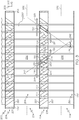
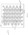
- the first hollow members 230 are disposed within and may extend across the first flow passages 206. Also, as shown in FIG. 3 , the first end 236 may be fluidly connected to one of the second flow passages 256, and the second end 238 may be fluidly connected to a neighboring second flow passage 256. As shown in FIG. 5 , there may be a plurality of first holes 244 through the separator members 220. The first holes 244 may fluidly connect the interior 234 of a respective first hollow member 230 to the second flow passage 256. Accordingly, fluid within one second flow passage 256 may flow through the first hollow members 230 to the neighboring second flow passage 256. This fluid flow is indicated by arrows 261 in FIG.
- a second fluid flows from the second flow passage 256 of the intermediate second flow structure 259, through one of the first hollow members 230, to the second flow passage 256 of the lower second flow structure 255.
- the second fluid is also shown flowing back to the second flow passage 256 of the intermediate second flow structure 259 through another first hollow member 230.
- the first fluid may be flowing through the first flow passage 206 and flowing around the first flow hollow members 230.
- the first and second fluids may have different temperatures, and the first hollow members 230 may be formed with materials having high heat transfer properties. Accordingly, the second fluid may exchange heat with the first fluid as the second fluid passes through the first hollow member 230 that is in direct contact with the first fluid.
- the arrangement of the first hollow members 230 may be configured to provide desirable heat transfer properties, to reduce pressure drop across the heat exchanger 200, etc.
- the first hollow members 230 may be disposed at an angle 242 with respect to the separator member 220 and with respect to the second flow axis 262.
- the first hollow members 230 are inclined within the plane defined by the second axis 202 and the third axis 203.
- the first hollow members 230 are inclined generally with respect to the fluid flow path (i.e., with respect to the second flow axis 262).
- the first end 236 and the second end 238 may be spaced apart with respect to the second axis 202.
- the first end 236 of the first hollow member 230 may be closer to the inlet 260 of the second flow passage 256
- the second end 240 may be closer to the outlet 258 of the second flow passage 256, or vice versa.
- this inclined orientation may provide a pressure differential between the first end 236 and the second end 238 of the first hollow member 230.
- the pressure differential may force second fluid through the first hollow members 230. This can enhance the heat transfer performance of the heat exchanger 200.
- scoop-like features may be implemented at the inlet ends (e.g., the first ends 236) to increase the flow rate.
- groups of the first hollow members 230 may be substantially aligned and arranged in rows (extending along the second axis 202). There may be multiple rows of the first hollow members 230, and the rows may be spaced apart along the first axis 201. In some embodiments, there may be a first row 246 and a second row 248 of first hollow members 230. The first row 246 may be offset from the second row 248 at a distance 253 measured along the second axis 202. The angle 242 of the hollow members 230 within the first row 246 may be different from the angle 242 of the hollow members 230 within the second row 248.
- the angle 242 of the hollow members 230 of the first row 246 may be substantially equal and opposite the angle 242 of the hollow members 230 of the second row 248 as shown in FIG. 3 .
- the angle 242 of the hollow members 230 of the first row 246 may be forty-five degrees (45°) in some embodiments, the angle 242 of the hollow members 230 of the second row 248 may be negative forty-five degrees (-45°).
- the heat exchanger 200 may include a plurality of second hollow members 280.
- the second hollow members 280 may be configured as tubes, cylinders, pipes, or other fluid conduit. Accordingly, as shown in FIG. 4 , the second hollow members 280 may include an outer shell 282 and an interior 284 that is hollow.
- the second hollow members 280 may have a rounded (e.g., circular) cross section on its outer diameter surface as well as its inner diameter surface.
- the second hollow members 280 may have a diameter between approximately 0,1 to 0,5 cm.
- the second hollow members 280 may have a length between approximately 0,12 to 0,76 cm.
- Each second hollow member 280 may include a first end 286 and a second end 288 ( FIG. 4 ).
- the second hollow members 280 may also include a respective second cross-flow axis 290, which extends between the first end 286 and the second end 288.
- the first cross-flow axis 290 is substantially straight.
- the first end 286 may be fixedly attached to one of the separator members 220, and the second end 288 may be fixedly attached to an opposing one of the separator members 220.
- the second cross-flow axis 290 of the second hollow members 280 may be oriented at non-orthogonal angles 292 with respect to the attached separator member 220. In some embodiments, different hollow members 280 may be disposed at different angles 292 with respect to a common separator member 220.
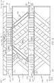
- the second hollow members 280 may be disposed within and may extend across the second flow passages 256. Also, as shown in FIG. 4 , the first end 286 may be fluidly connected to one of the first flow passages 206, and the second end 288 may be fluidly connected to a neighboring first flow passage 206.
- FIG. 5 shows openings in the separator member 220, and as shown, there may be a plurality of second holes 294 that fluidly connect the interior 284 of the second hollow members 280 to the first flow passage 206. Accordingly, fluid within one first flow passage 206 may flow through the second hollow members 280 to the neighboring first flow passage 206. This fluid flow is indicated by arrows 263 in FIG.
- a first fluid flows from the first flow passage 206 of the lower first flow structure 205, through one of the second hollow members 280, to the first flow passage 206 of the upper first flow structure 207.
- the first fluid is also shown flowing back to the first flow passage 206 of the lower first flow structure 205 through another second hollow member 280.
- the second fluid may be flowing through the second flow passage 256 and flowing around the second hollow members 280.
- the first and second fluids may have different temperatures, and the second hollow members 280 may be formed with materials having high heat transfer properties. Accordingly, the first fluid may exchange heat with the second fluid as the first fluid passes through the second hollow member 280.
- the arrangement of the second hollow members 280 may be configured to provide desirable heat transfer properties, to reduce pressure drop across the heat exchanger 200, etc.
- the second hollow members 280 may be disposed at an angle 292 with respect to the separator member 220 and with respect to the first flow axis 212.
- the second hollow members 280 are inclined within the plane defined by the first axis 201 and the third axis 203.
- the second hollow members 280 may be inclined generally with respect to the fluid flow path (i.e., with respect to the first flow axis 212).
- the first end 286 and the second end 288 may be spaced apart with respect to the first axis 201. In other words, the first end 286 of the second hollow member 280 may be closer to the inlet 208 of the first flow passage 206, and the second end 288 may be closer to the outlet 210 of the first flow passage 206, or vice versa.
- this inclined orientation may provide a pressure differential within the fluid flow between the first end 286 and the second end 288.
- the pressure differential may force the fluid through the second hollow members 280. This flow through the member enhances the heat transfer performance of the heat exchanger 200.
- scoop-like features may be implemented at the inlet ends (e.g., the first ends 286) to increase the flow rate.
- groups of the second hollow members 280 may be substantially aligned and arranged in rows (extending along the first axis 201). There may be multiple rows of the second hollow members 280, and the rows may be spaced apart along the second axis 202.
- the first row 296 may be offset from the second row 298 at a distance 251 measured along the first axis 201.
- the angle 292 ( FIG. 4 ) of the hollow members 230 within the first row 296 may be different from the angle 292 of the hollow members 280 within the second row 298.
- the angle 292 of the hollow members 280 of the first row 296 may be substantially equal and opposite the angle 292 of the hollow members 280 of the second row 298 as shown in FIG. 4 .
- the angle 292 of the hollow members 280 of the first row 296 may be forty-five degrees (45°) in some embodiments, and the angle 292 of the hollow members 280 of the second row 298 may be negative forty-five degrees (-45°).
- the interior 234 of the first hollow members 230 may have a smaller cross sectional area (e.g., smaller inner diameter) than that of the interior 284 of the second hollow members 280. Furthermore, the length of the first hollow members 230 (measured from the first end 236 to the second end 238 along the axis 240) may be shorter than that of the second hollow member 280. The dimensions of the second hollow members 280 may provide a large amount of exposure within the flow of fluid within the second passages 256 to promote heat transfer between the second fluid within the second passages 256 and the first fluid within the second hollow members 280. These lengths, diameters and angles may be configured according to the performance and other requirements of the heat exchanger 200.
- the first flow passages 206 as well as the second hollow members 280 may receive a hot first fluid
- the second flow passages 256 as well as the first hollow members 230 may receive a cool second fluid. Accordingly, heat may transfer from the first fluid to the second fluid via flow through the heat exchanger 200.
- the heat exchanger 200 may be configured to direct flow of the first fluid generally along the flow axis 212 as well as in a cross-flow direction along the axis 290 across the second flow passage 256. Likewise, the heat exchanger 200 may be configured to direct flow of the second fluid generally along the flow axis 262 as well as in a cross-flow direction along the axis 240 across the first flow passage 206.
- the first hollow members 230 may be inclined or otherwise oriented to direct flow of the second fluid along the axis 262 of the second passageway 256.
- the second hollow members 280 may be inclined or otherwise oriented to direct flow of the first fluid along the axis 212 of the first passageway 206. Accordingly, the fluids may flow in a variety of directions through the heat exchanger 200 to increase efficiency.
- the plurality of first hollow members 230 may be inclined within a plane (e.g., the plane defined by the second and third axes 202, 203), and the plurality of second hollow members 280 may be inclined within a plane (e.g., the plane defined by the first and third axes 201, 203.
- the plane of the first hollow members 230 may be approximately orthogonal to the plane of the second hollow members 280. Other orientations are within the scope of the present disclosure as well.
- a portion of the first fluid may flow around the criss-crossing, lattice-like arrangement of the first hollow members 230 as the first fluid flows through the first passageway 206.
- a portion of the first fluid may flow through second hollow members 280 to an adjacent first passageway 206.
- the first fluid has an "external flow” about the first hollow members 230 for heat exchange with the second fluid
- the first fluid has an "internal flow” through the second hollow members 280 for heat exchange with the second fluid.
- a portion of the second fluid flows around the criss-crossing, lattice-like arrangement of the second hollow members 280 as the second fluid flows through the second passageway 256.
- the second fluid may flow through first hollow members 230 to an adjacent second passageway 256. Accordingly, the second fluid has an "external flow" about the second hollow members 280 for heat exchange with the first fluid, and the second fluid has an "internal flow” through the first hollow members 230 for heat exchange with the first fluid.
- the lattice-like arrangement of the first hollow members 230 may be oriented substantially perpendicular to the flow direction through the first passageway 206
- the lattice-like arrangement of the second hollow members 280 may be oriented substantially perpendicular to the flow direction through the second passageway 256.
- the flows are in a cross flow manner with respect to each other; therefore, the lattice-like arrangements may be substantially perpendicular with respect to each other. Accordingly, this provides a high degree of exposure for highly efficient heat transfer between the two fluids.
- Flow apportionment throughout the heat exchanger may be accomplished by computational fluid dynamics (CFD) analysis and optimization, for example, utilizing conjugate heat transfer analysis, where the fluid mechanics and structural temperatures are solved in a single coupled analysis.
- CFD computational fluid dynamics
- Commercial software codes such as CD-adapco STAR-CCM+ from Siemens AG of Kunststoff, Germany or ANSYS CFX are examples of such codes that may be used by those skilled in the art.
- the dimensions and quantities of the first hollow members 230 and the geometric spacing between adjacent second hollow members 280 may be configured to provide suitable flow inside the first hollow members 230 and suitable flow around the second hollow members 280.
- the dimensions and quantities of the second hollow members 280 and the geometric spacing between adjacent first hollow members 230 may be configured to provide suitable flow inside the second hollow members 280 and suitable flow around the first hollow members 230.
- Various types of flow scoops may be employed on the first end 236 inlet of one or more first hollow members 230 to facilitate obtaining a predetermined flow 261 through the first hollow members 230.
- various types of flow scoops may be employed on the first end 286 inlet of one or more second hollow members 280 to facilitate obtaining a predetermined flow 263 through the second hollow members 280.
- FIG. 6 additional embodiments of the heat exchanger 300 are illustrated according to the present disclosure. Only a portion is shown for clarity.
- the heat exchanger 300 may be substantially similar to the embodiment of FIGS 2-5 except as noted. Components that correspond to those of FIGS. 2-5 are indicated with corresponding reference numbers increased by 100.
- the first hollow members 330 may have a contoured axis 340. In other words, the first hollow members 330 may curve as they extend across the first flow passage 306. Like the embodiment of FIGS. 2-5 the first hollow members 330 are attached to the separator members 320 at non-orthogonal angles. Also, the first hollow members 330 may be oriented with respect to the flow axes 362 such that the first hollow members 330 direct flow of the second fluid somewhat along the axis 362 of the second passageways 356. Moreover, as shown in Figure 6 , the cross-sectional area of at least one hollow member 330 may vary along its length, for example, to increase the flow through the hollow member 330. It will be appreciated that second hollow members of the heat exchanger 300 may be similar to the first hollow members 330 and may curve and attach to the separator members 320 at non-orthogonal angles as well.
- FIGS. 7 and 8 additional embodiments of the heat exchanger 400 are illustrated according to the present disclosure. Only a portion is shown for clarity.
- the heat exchanger 400 may be substantially similar to the embodiment of FIGS 2-5 except as noted. Components that correspond to those of FIGS. 2-5 are indicated with corresponding reference numbers increased by 200.
- the first hollow members 430 may include at least one projection 483 that projects outward from the outer shell 432 into the first flow passage 406.
- the projection 483 may be a thin, annular disc-like fin that encircles the outer shell 432 in some embodiments.
- the projections 483 may promote heat transfer for higher efficiency operation of the heat exchanger 400.
- Other projections 483 fall within the scope of the present disclosure, such as pins, helical projections, etc.
- the second hollow members and/or other portions of the heat exchanger 400 may include projections as well.
- the heat exchanger 400 may include one or more scoop structures 499.
- the scoop structure 499 may project from the separator member 420, proximate the first end 436 (i.e., the inlet end) of the first hollow member 430.
- the scoop structure 499 may also curve in an upstream direction within the second passageway 456.
- the scoop structure 499 may direct flow of the second fluid into the first hollow member 430.
- the heat exchangers of the present disclosure may be manufactured in a variety of ways without departing from the scope of the present disclosure. It will be appreciated that certain features of the presently described heat exchange systems may be prohibitively expensive to manufacture using conventional manufacturing techniques. These features include the inclined or contoured surfaces, the interspersed cross-flow hollow members, the varying wall thickness features, among others. As such, designs in accordance with the present disclosure are not known in the prior art.
- the heat exchanger of the present disclosure may be formed using additive manufacturing techniques (e.g., 3D printing techniques).
- additive manufacturing techniques e.g., 3D printing techniques
- the heat exchanger may be formed more accurately and at a significantly reduced cost as compared to traditional manufacturing techniques.
- the heat exchanger may be a substantially unitary, one-piece component using these techniques.
- the flow structures, the hollow members, projections, and other features of the heat exchanger may be integrally connected so as to be a unitary, one-piece heat exchanger.
- Additive manufacturing techniques include, for example, direct metal laser sintering (DMLS - a form of direct metal laser fusion (DMLF)) or electron beam additive manufacturing.
- the heat exchanger may be manufactured from aluminum, titanium, steel, and nickel-based alloys. Still further, casting or metal injection molding (MIM) may be employed.
- the heat exchanger of the present disclosure may be constructed using techniques disclosed in US Patent No. 2013/0236299 , the disclosure of which is hereby incorporated by reference in its entirety.
- the heat exchanger of the present disclosure provides highly efficient heat exchange.
- the heat exchanger may be lightweight, and yet, robust and strong for a long operating life. Additionally, the heat exchanger may provide manufacturing benefits as well.
Landscapes
- Engineering & Computer Science (AREA)
- Physics & Mathematics (AREA)
- Mechanical Engineering (AREA)
- General Engineering & Computer Science (AREA)
- Thermal Sciences (AREA)
- Geometry (AREA)
- Chemical & Material Sciences (AREA)
- Combustion & Propulsion (AREA)
- Heat-Exchange Devices With Radiators And Conduit Assemblies (AREA)
Description
- The present disclosure generally relates to a heat exchanger and, more particularly, relates to a heat exchanger with an interspersed arrangement of cross-flow structures.
- Heat exchangers have been developed for various devices, such as engine systems, computer systems, HVAC systems, and more. The heat exchangers are configured for directing heat within the device to components where such heat is beneficial to its operating performance, for directing heat away from components that normally cannot tolerate high temperatures, and/or where system operational constraints require controlled temperatures.
- For example, gas turbine engines may include various heat exchangers. In one example, a class of heat exchangers known as recuperators have been developed to recover heat from the engine exhaust, which is otherwise wasted energy, and redirect the recovered engine exhaust heat to the pre-combustion portion of the engine, to increase its overall engine efficiency. Specifically, the recuperator is a heat exchanger that transfers some of the waste heat in the exhaust to the compressed air before it enters the combustion portion of the engine, thereby preheating it before entering the fuel combustor stage. Since the compressed air has been pre-heated, less fuel is needed to heat the compressed air/fuel mixture up to the desired turbine inlet temperature. By recovering some of the energy usually lost as waste heat, the recuperator can make a gas turbine engine significantly more efficient.
- In another example, cooling air may be provided to various turbine engine components using cooling air extracted from other parts of the engine. More specifically, in some gas turbine engines, cooling air is extracted from the discharge of the compressor, and is then directed to certain portions of the turbine. During some operating conditions, the air that is extracted from the engine for cooling may be at temperatures that require the air to be cooled before being directed to the particular component requiring cooling. To achieve the required cooling, cooling air may be directed through one or more heat exchangers within the engine.
- Conventional heat exchangers may be too heavy, bulky, or may not provide acceptable performance characteristics. Other heat exchangers may be expensive or difficult to manufacture. Moreover, some heat exchangers may be susceptible to thermo-mechanical fatigue, which reduces their service life or necessitates costly repairs or replacement.
- Hence, there is a need for improved heat exchangers for use in gas turbine engines and other applications having improved efficiency, reduced manufacturing costs, and increased operating lifespan. The present disclosure addresses at least these needs.
US 3983935 (Henrion ) describes a heat exchanger with corrugated walls and baffles.GB1506721 - The present invention is defined by independent claim 1. Further preferred embodiments are defined in the dependent claims.
- The heat exchanger of the invention includes a separator member that divides a first flow passage of the heat exchanger from a second flow passage of the heat exchanger. The heat exchanger also includes a plurality of first hollow members that extend across the first flow passage and that are attached to the separator member at respective non-orthogonal angles. The plurality of first hollow members being fluidly connected to the second flow passage. Moreover, the heat exchanger includes a plurality of second hollow members that extend across the second flow passage and that are attached to the separator member at respective non-orthogonal angles. The plurality of second hollow members are fluidly connected to the first flow passage. The first flow passage is configured to receive a first fluid that flows through the first flow passage and into the plurality of second hollow members. The second flow passage is configured to receive a second fluid that flows through the second flow passage and into the plurality of first hollow members. The first fluid is configured to exchange heat with the second fluid as the first fluid flows through the first flow passage and over the plurality of first hollow members. The second fluid is configured to exchange heat with the first fluid as the second fluid flows through the second flow passage and over the plurality of second hollow members.
- The heat exchanger includes a first separator member and a second separator member. The inventive heat exchanger is characterised in that different ones of the plurality of first hollow members are disposed at different non-orthogonal angles with respect to one of the plurality of separator members.
- Moreover, a method of manufacturing a heat exchanger is disclosed (not forming part of the invention) that includes forming a first flow structure with a first flow passage and a second flow structure with a second flow passage. This includes forming a separator member that divides the first flow passage from the second flow passage. The method also includes forming a plurality of first hollow members that extend across the first flow passage and that are attached to the separator member at respective non-orthogonal angles. The plurality of first hollow members are fluidly connected to the second flow passage. The method additionally includes forming a plurality of second hollow members that extend across the second flow passage and that are attached to the separator member at respective non-orthogonal angles. The plurality of second hollow members are fluidly connected to the first flow passage. The first flow passage is configured to receive a first fluid that flows through the first flow passage and into the plurality of second hollow members. The second flow passage is configured to receive a second fluid that flows through the second flow passage and into the plurality of first hollow members. The first fluid is configured to exchange heat with the second fluid as the first fluid flows through the first flow passage and over the plurality of first hollow members. The second fluid is configured to exchange heat with the first fluid as the second fluid flows through the second flow passage and over the plurality of second hollow members.
- The present invention will hereinafter be described in conjunction with the following drawing figures, wherein like numerals denote like elements, and wherein:
-
FIG. 1 is a schematic side view of a gas turbine engine with a heat exchanger according to exemplary embodiments of the present disclosure; -
FIG. 2 is a perspective view of a heat exchanger according to example embodiments of the present disclosure, wherein the heat exchanger may be configured for use within the gas turbine engine ofFIG. 1 ; -
FIG. 3 is a section view of the heat exchanger taken along the line 3-3 ofFIG. 2 ; -
FIG. 4 is a section view of the heat exchanger taken along the line 4-4 ofFIG. 2 ; -
FIG. 5 is a section view of the heat exchanger taken along the line 5-5 ofFIG. 2 ; -
FIG. 6 is a section view of the heat exchanger according to additional embodiments of the present disclosure; -
FIG. 7 is a section view of the heat exchanger according to additional embodiments of the present disclosure; and -
FIG. 8 is a section view of a hollow member of the heat exchanger taken along the line 8-8 ofFIG. 7 . - The following detailed description is merely exemplary in nature and is not intended to limit the present disclosure or the application and uses of the present disclosure. As used herein, the word "exemplary" means "serving as an example, instance, or illustration." Thus, any embodiment described herein as "exemplary" is not necessarily to be construed as preferred or advantageous over other embodiments. Furthermore, as used herein, numerical ordinals such as "first," "second," "third," etc. simply denote different singles of a plurality unless specifically defined by language in the appended claims. Furthermore, there is no intention to be bound by any expressed or implied theory presented in the preceding technical field, background, brief summary, or the following detailed description.
- The present disclosure relates to a heat exchanger, which may be suitable for use in gas turbine engines and other applications. The heat exchanger may provide improved heat transfer performance, increased manufacturability, and/or improved operational lifespan. In one implementation, the heat exchanger is embodied as a recuperator or other similar component for heating a fluid (e.g., air) prior entry into another component (e.g., a combustor). In another implementation, the heat exchanger is embodied as a cooling air heat exchanger for reducing the temperature of cooling fluid (e.g., air) prior to its delivery to another component that requires cooling (e.g., a turbine component or cooling system). However, it will be appreciated that the presently disclosed heat exchanger is not limited to use in the aforementioned embodiments. Rather, it is expected that the heat exchanger disclosed herein will be suitable for use in a wide array of applications. Some non-limiting examples include engine oil and/or fuel cooling, auxiliary power units, environmental control systems, chemical reaction systems, and any other systems where heat transfer/exchange between two fluid media is either required or desirable.
- In general, the heat exchanger includes a plurality of structures that define first flow passages and second flow passage that are disposed in an alternating arrangement. The heat exchanger also includes a plurality of first hollow members (e.g., tubes, conduits, etc.) that extend across a respective first flow passage and that are fluidly connected to opposing second flow passages. Moreover, the heat exchanger may include a plurality of second hollow members (e.g., tubes, conduits, etc.) that extend across a respective second flow passage and that are fluidly connected to opposing first flow passages. Accordingly, a first fluid may flow along a first flow axis through one of the first flow passages, and the first fluid may flow via the second hollow members to another first flow passage. Likewise, a second fluid may flow along a second flow axis through one of the second flow passages, and the second fluid may flow via the first hollow members to another second flow passage. The first fluid and the second fluid may exchange heat during such flow.
- The first hollow members extend along an axis that is disposed at a non-orthogonal angle relative to the second flow axis of the second flow passage. Accordingly, a pressure differential may exist along the first hollow member to draw the second fluid therethrough. Likewise, the second hollow members may extend along an axis that is disposed at a non-orthogonal angle relative to the first flow axis. Accordingly, a pressure differential may exist along the second hollow member to draw the first fluid therethrough. As such, the heat exchanger may be highly efficient, lightweight, and may have a relatively long operating life.
- Referring now particularly to
FIG. 1 , a simplified cross section view of an exemplarygas turbine engine 100 is depicted. The depictedengine 100 includes anintake section 102, acompressor section 104, acombustion section 106, aturbine section 108, and anexhaust section 112. Theintake section 102,compressor section 104,combustion section 106,turbine section 108, andexhaust section 112 are all mounted within anacelle 114. Thecompressor section 104,combustion section 106, andturbine section 108 are all mounted within anengine case 116. - The
intake section 102 includes afan 118, which draws air into theengine 100 and accelerates it. A fraction of the accelerated fan air that is exhausted from thefan 118 is directed through a fanair bypass duct 122, which is defined by anouter fan duct 124, and which is spaced apart from and surrounds aninner fan duct 126. Most of the fan air that flows through the fanair bypass duct 122 is discharged from thebypass duct 122 to generate a forward thrust. The fraction of fan air that does not flow into the fanair bypass duct 122 is directed into thecompressor section 104. - The
compressor section 104 can include one or more compressors. Theengine 100 depicted inFIG. 1 includes two compressors: anintermediate pressure compressor 132 and ahigh pressure compressor 134. No matter the number of compressors it includes, the air that is directed into thecompressor section 104 is pressurized to a relatively high pressure. The relatively high pressure air that is discharged from thecompressor section 104 is directed into thecombustion section 106. - The
combustion section 106 includes acombustor 136 that is coupled to receive both the relatively high pressure air and atomized fuel. The relatively high pressure air and atomized fuel are mixed within thecombustor 136 and the mixture is ignited to generate combusted air. The combusted air is then directed into theturbine section 108. - The depicted
turbine section 108 includes three turbines: ahigh pressure turbine 138, anintermediate pressure turbine 142, and alow pressure turbine 144, though it should be appreciated that any number of turbines may be included. The combusted air directed into theturbine section 108 expands through each ofturbines propulsion nozzle 146 disposed in theexhaust section 112 to provide additional forward thrust. As theturbines gas turbine engine 100 via concentrically disposed shafts or spools as best seen inFIG. 1 . - The
engine 100 may further include at least one heat exchanger 200 (shown schematically). In some embodiments, theheat exchanger 200 may be included in a coolingair system 190 for providing cooling air to cool various portions and/or components within theengine 100. For example, theheat exchanger 200 of the coolingair system 190 may extract cooling air from the discharge of thecompressor section 104 and direct the cooling air to theturbine section 108. Additionally, or in the alternative, theheat exchanger 200 may be included in arecuperator 192 for providing heated air to various portions and/or components within theengine 100. For example, therecuperator 192 may recover hot engine exhaust gas from thecombustor 136 and theheat exchanger 200 therein may transfer heat from the exhaust gas to the air flowing into thecombustor 136. - With reference to
FIG. 2 , theheat exchanger 200 will be discussed in greater detail according to example embodiments. For clarity and ease of illustration, portions of theheat exchanger 200 are hidden from view. Specifically, an upper portion is sectioned away at an angle to reveal interior features. Also, for reference purposes, a Cartesian coordinate system is included with afirst axis 201, asecond axis 202, and athird axis 203. - Generally, the
heat exchanger 200 may include a plurality offirst flow structures 204 and a plurality ofsecond flow structures 254. As shown in the illustrated embodiment, thefirst flow structures 204 and thesecond flow structures 254 may be generally box-shaped and hollow in some embodiments. Thesecond flow structures 254 may be larger than thefirst flow structures 204 in some embodiments. In other embodiments, thesecond flow structures 254 may be smaller than thefirst flow structures 204. It will be appreciated, however, that the shape, arrangement, geometry, etc. of the first andsecond flow structures second flow structures heat exchanger 200. In some embodiments, for example, the first andsecond flow structures heat exchangers 200 conforms to the curvature of adjacent components of the engine 100 (e.g., to form an annular ring). Other shapes and sizes are possible to conform to available installation space in other implementations as well. - The
first flow structures 204 may be substantially similar to each other. Thefirst flow structures 204 may define respectivefirst flow passages 206 that receive flow of a first fluid (e.g., a first gas). Thefirst flow passages 206 may each include aninlet 208 and anoutlet 210, and afirst flow axis 212 may extend between theinlet 208 and theoutlet 210. In some embodiments, thefirst flow axis 212 may be generally straight and parallel to thefirst axis 201. - Also, the
second flow structures 254 may be substantially similar to each other. The second flowsstructures 254 may define respectivesecond flow passages 256 that receive flow of a second fluid (e.g., a second gas). Thesecond flow passages 256 may each include aninlet 260 and anoutlet 258, and asecond flow axis 262 may extend between theinlet 260 and theoutlet 258. In some embodiments, thesecond flow axis 262 may be generally straight and parallel to thesecond axis 202. Thesecond flow axis 262 may be substantially orthogonal in a cross flow arrangement to thefirst flow axis 212 in some embodiments. In additional embodiments, theheat exchanger 200 may have a counterflow arrangement. Also, theheat exchanger 200 may be conformal in nature where theflow structures - The first and
second flow structures third axis 203. Also, thefirst flow structures 204 and thesecond flow structures 254 may be in an alternating arrangement withfirst flow structures 204 disposed between neighboring pairs of thesecond flow structures 254 and vice versa. This pattern may be continued until there is a suitable number of first andsecond flow structures heat exchanger 200 includes a lowerfirst flow structure 205 and an upperfirst flow structure 207. Also, in the illustrated embodiment, theheat exchanger 200 includes a lowersecond flow structure 255, an uppersecond flow structure 257, and an intermediatesecond flow structure 259. (InFIG. 2 , portions of the upperfirst flow structure 207 and the uppersecond flow structure 257 are hidden for clarity.) The intermediatesecond flow structure 259 may be disposed between the opposing lowerfirst flow structure 205 and upperfirst flow structure 207. The lowerfirst flow structure 205 may be disposed between the opposing lowersecond flow structure 255 and intermediatesecond flow structure 259. The uppersecond flow structure 207 may be disposed between the opposing intermediatesecond flow structure 259 and uppersecond flow structure 257. It will be appreciated that there may be additional flow structures within theheat exchanger 200 without departing from the scope of the present disclosure. - The
heat exchanger 200 includes a plurality ofseparator members 220. Theseparator members 220 may be relatively flat, unitary panels. Accordingly, theseparator members 220 may be substantially parallel to a plane defined by thefirst axis 201 and thesecond axis 202. Eachseparator member 220 divides one of thefirst flow passages 206 from an adjacentsecond flow passage 256. Thus, in some embodiments, theseparator member 220 may partly define one of thefirst flow structures 204 and may partly define an adjacent one of thesecond flow structures 254. - The
first flow structures 204 may also include a respectivefirst side wall 222 and a respectivesecond side wall 224. The first andsecond side walls third axes second side walls second axis 202 to define a flow width. Accordingly, the first andsecond side walls separator members 220 may cooperate to define theinlet 208 of one of thefirst flow passages 206. Likewise, the first andsecond side walls separator members 220 may cooperate to define theoutlet 210 of one of thefirst flow passages 206. - The
second flow structures 254 may also include a respectivethird side wall 226 and a respectivefourth side wall 228. The third andfourth side walls third axes fourth side walls first axis 201. Accordingly, the third andfourth side walls separator members 220 may cooperate to define theinlet 260 of one of thesecond flow passages 256. Likewise, the third andfourth side walls separator members 220 may cooperate to define theoutlet 258 of one of thesecond flow passages 256. - Referring now to
FIGS. 2 ,3 , and4 , the interior of thefirst flow structures 204 and thesecond flow structures 254 will be discussed. As shown, theheat exchanger 200 may include a plurality of support posts 209. The support posts 209 may be elongate and may extend substantially parallel to thethird axis 203. Also, the support posts 209 may have a rounded (e.g., circular) cross section. Moreover, the support posts 209 may have a solid core (as opposed to being hollow). The support posts 209 may be fixed at one end to aseparator member 220 and fixed at the opposite end to an opposingseparator member 220. In some embodiments, the support posts 209 may be disposed within and may extend across thefirst flow passages 206, substantially parallel to thethird axis 203. The support posts 209 may provide load bearing support to theheat exchanger 200. The arrangement of the support posts 209 may be tailored for providing needed support. For example, as shown in the embodiment ofFIG. 2 , groups of the support posts 209 may be substantially aligned and arranged in rows (extending along the second axis 202). There may be multiple rows of the support posts 209, and the rows may be spaced apart along thefirst axis 201. Accordingly, the support posts 209 may provide high strength and robustness to theheat exchanger 200. In some embodiments, the support posts 209 may also provide a heat transfer path between fluids in the first andsecond flow passages - It will be appreciated that the support posts 209 may be configured differently than the embodiments illustrated. For example, the
heat exchanger 200 may includesupport posts 209 that are disposed within thesecond flow passage 256. Also, the support posts 209 may, in some embodiments, include fins or other projections that increase the heat transfer properties of thesupport post 209. - Moreover, the
heat exchanger 200 may include a plurality of firsthollow members 230. The firsthollow members 230 may be configured as tubes, cylinders, pipes, or other fluid conduits. Accordingly, as shown inFIG. 3 , the firsthollow members 230 may include anouter shell 232 and an interior 234 that is hollow. In some embodiments, the firsthollow members 230 may have a rounded (e.g., circular) cross section on its outer diameter surface as well as its inner diameter surface. In some embodiments, the firsthollow members 230 may have a diameter between approximately 0,1 to 0,5 cm. Also, in some embodiments, the firsthollow members 230 may have a length between approximately 0,12 to 0,76 cm. - Each first
hollow member 230 may include afirst end 236 and a second end 238 (FIG. 3 ). The firsthollow members 230 may also include a respective firstcross-flow axis 240, which extends between thefirst end 236 and thesecond end 238. In some embodiments, the firstcross-flow axis 240 is substantially straight. - The
first end 236 may be fixedly attached to one of theseparator members 220, and thesecond end 238 may be fixedly attached to an opposing one of theseparator members 220. The firstcross-flow axis 240 of the firsthollow member 230 are oriented at anon-orthogonal angle 242 with respect to the attachedseparator member 220. The differenthollow members 230 are disposed atdifferent angles 242 with respect to acommon separator member 220. - The first
hollow members 230 are disposed within and may extend across thefirst flow passages 206. Also, as shown inFIG. 3 , thefirst end 236 may be fluidly connected to one of thesecond flow passages 256, and thesecond end 238 may be fluidly connected to a neighboringsecond flow passage 256. As shown inFIG. 5 , there may be a plurality offirst holes 244 through theseparator members 220. Thefirst holes 244 may fluidly connect theinterior 234 of a respective firsthollow member 230 to thesecond flow passage 256. Accordingly, fluid within onesecond flow passage 256 may flow through the firsthollow members 230 to the neighboringsecond flow passage 256. This fluid flow is indicated byarrows 261 inFIG. 3 , wherein a second fluid flows from thesecond flow passage 256 of the intermediatesecond flow structure 259, through one of the firsthollow members 230, to thesecond flow passage 256 of the lowersecond flow structure 255. The second fluid is also shown flowing back to thesecond flow passage 256 of the intermediatesecond flow structure 259 through another firsthollow member 230. Meanwhile, the first fluid may be flowing through thefirst flow passage 206 and flowing around the first flowhollow members 230. The first and second fluids may have different temperatures, and the firsthollow members 230 may be formed with materials having high heat transfer properties. Accordingly, the second fluid may exchange heat with the first fluid as the second fluid passes through the firsthollow member 230 that is in direct contact with the first fluid. - The arrangement of the first
hollow members 230 may be configured to provide desirable heat transfer properties, to reduce pressure drop across theheat exchanger 200, etc. As stated, the firsthollow members 230 may be disposed at anangle 242 with respect to theseparator member 220 and with respect to thesecond flow axis 262. The firsthollow members 230 are inclined within the plane defined by thesecond axis 202 and thethird axis 203. As such, the firsthollow members 230 are inclined generally with respect to the fluid flow path (i.e., with respect to the second flow axis 262). Also, thefirst end 236 and thesecond end 238 may be spaced apart with respect to thesecond axis 202. In other words, thefirst end 236 of the firsthollow member 230 may be closer to theinlet 260 of thesecond flow passage 256, and thesecond end 240 may be closer to theoutlet 258 of thesecond flow passage 256, or vice versa. - Accordingly, this inclined orientation may provide a pressure differential between the
first end 236 and thesecond end 238 of the firsthollow member 230. The pressure differential may force second fluid through the firsthollow members 230. This can enhance the heat transfer performance of theheat exchanger 200. Also, scoop-like features may be implemented at the inlet ends (e.g., the first ends 236) to increase the flow rate. - Furthermore, as shown in the embodiment of
FIGS. 2 ,3 , and5 , groups of the firsthollow members 230 may be substantially aligned and arranged in rows (extending along the second axis 202). There may be multiple rows of the firsthollow members 230, and the rows may be spaced apart along thefirst axis 201. In some embodiments, there may be afirst row 246 and asecond row 248 of firsthollow members 230. Thefirst row 246 may be offset from thesecond row 248 at adistance 253 measured along thesecond axis 202. Theangle 242 of thehollow members 230 within thefirst row 246 may be different from theangle 242 of thehollow members 230 within thesecond row 248. In some embodiments, theangle 242 of thehollow members 230 of thefirst row 246 may be substantially equal and opposite theangle 242 of thehollow members 230 of thesecond row 248 as shown inFIG. 3 . For example, theangle 242 of thehollow members 230 of thefirst row 246 may be forty-five degrees (45°) in some embodiments, theangle 242 of thehollow members 230 of thesecond row 248 may be negative forty-five degrees (-45°). - In addition, the
heat exchanger 200 may include a plurality of secondhollow members 280. The secondhollow members 280 may be configured as tubes, cylinders, pipes, or other fluid conduit. Accordingly, as shown inFIG. 4 , the secondhollow members 280 may include anouter shell 282 and an interior 284 that is hollow. In some embodiments, the secondhollow members 280 may have a rounded (e.g., circular) cross section on its outer diameter surface as well as its inner diameter surface. In some embodiments, the secondhollow members 280 may have a diameter between approximately 0,1 to 0,5 cm. Also, in some embodiments, the secondhollow members 280 may have a length between approximately 0,12 to 0,76 cm. - Each second
hollow member 280 may include afirst end 286 and a second end 288 (FIG. 4 ). The secondhollow members 280 may also include a respective secondcross-flow axis 290, which extends between thefirst end 286 and thesecond end 288. In some embodiments, the firstcross-flow axis 290 is substantially straight. - The
first end 286 may be fixedly attached to one of theseparator members 220, and thesecond end 288 may be fixedly attached to an opposing one of theseparator members 220. The secondcross-flow axis 290 of the secondhollow members 280 may be oriented atnon-orthogonal angles 292 with respect to the attachedseparator member 220. In some embodiments, differenthollow members 280 may be disposed atdifferent angles 292 with respect to acommon separator member 220. - In some embodiments, the second
hollow members 280 may be disposed within and may extend across thesecond flow passages 256. Also, as shown inFIG. 4 , thefirst end 286 may be fluidly connected to one of thefirst flow passages 206, and thesecond end 288 may be fluidly connected to a neighboringfirst flow passage 206.FIG. 5 shows openings in theseparator member 220, and as shown, there may be a plurality ofsecond holes 294 that fluidly connect theinterior 284 of the secondhollow members 280 to thefirst flow passage 206. Accordingly, fluid within onefirst flow passage 206 may flow through the secondhollow members 280 to the neighboringfirst flow passage 206. This fluid flow is indicated byarrows 263 inFIG. 4 , wherein a first fluid flows from thefirst flow passage 206 of the lowerfirst flow structure 205, through one of the secondhollow members 280, to thefirst flow passage 206 of the upperfirst flow structure 207. The first fluid is also shown flowing back to thefirst flow passage 206 of the lowerfirst flow structure 205 through another secondhollow member 280. Meanwhile, the second fluid may be flowing through thesecond flow passage 256 and flowing around the secondhollow members 280. The first and second fluids may have different temperatures, and the secondhollow members 280 may be formed with materials having high heat transfer properties. Accordingly, the first fluid may exchange heat with the second fluid as the first fluid passes through the secondhollow member 280. - The arrangement of the second
hollow members 280 may be configured to provide desirable heat transfer properties, to reduce pressure drop across theheat exchanger 200, etc. As stated, the secondhollow members 280 may be disposed at anangle 292 with respect to theseparator member 220 and with respect to thefirst flow axis 212. In some embodiments, the secondhollow members 280 are inclined within the plane defined by thefirst axis 201 and thethird axis 203. As such, the secondhollow members 280 may be inclined generally with respect to the fluid flow path (i.e., with respect to the first flow axis 212). Also, thefirst end 286 and thesecond end 288 may be spaced apart with respect to thefirst axis 201. In other words, thefirst end 286 of the secondhollow member 280 may be closer to theinlet 208 of thefirst flow passage 206, and thesecond end 288 may be closer to theoutlet 210 of thefirst flow passage 206, or vice versa. - Accordingly, this inclined orientation may provide a pressure differential within the fluid flow between the
first end 286 and thesecond end 288. The pressure differential may force the fluid through the secondhollow members 280. This flow through the member enhances the heat transfer performance of theheat exchanger 200. Also, scoop-like features may be implemented at the inlet ends (e.g., the first ends 286) to increase the flow rate. - Furthermore, as shown in the embodiment of
FIGS. 2 and3 , groups of the secondhollow members 280 may be substantially aligned and arranged in rows (extending along the first axis 201). There may be multiple rows of the secondhollow members 280, and the rows may be spaced apart along thesecond axis 202. In some embodiments represented inFIG. 5 , there may be afirst row 296 and asecond row 298 of firsthollow members 230. Thefirst row 296 may be offset from thesecond row 298 at adistance 251 measured along thefirst axis 201. The angle 292 (FIG. 4 ) of thehollow members 230 within thefirst row 296 may be different from theangle 292 of thehollow members 280 within thesecond row 298. In some embodiments, theangle 292 of thehollow members 280 of thefirst row 296 may be substantially equal and opposite theangle 292 of thehollow members 280 of thesecond row 298 as shown inFIG. 4 . For example, theangle 292 of thehollow members 280 of thefirst row 296 may be forty-five degrees (45°) in some embodiments, and theangle 292 of thehollow members 280 of thesecond row 298 may be negative forty-five degrees (-45°). - The
interior 234 of the firsthollow members 230 may have a smaller cross sectional area (e.g., smaller inner diameter) than that of theinterior 284 of the secondhollow members 280. Furthermore, the length of the first hollow members 230 (measured from thefirst end 236 to thesecond end 238 along the axis 240) may be shorter than that of the secondhollow member 280. The dimensions of the secondhollow members 280 may provide a large amount of exposure within the flow of fluid within thesecond passages 256 to promote heat transfer between the second fluid within thesecond passages 256 and the first fluid within the secondhollow members 280. These lengths, diameters and angles may be configured according to the performance and other requirements of theheat exchanger 200. - In some embodiments, the
first flow passages 206 as well as the secondhollow members 280 may receive a hot first fluid, and thesecond flow passages 256 as well as the firsthollow members 230 may receive a cool second fluid. Accordingly, heat may transfer from the first fluid to the second fluid via flow through theheat exchanger 200. - The
heat exchanger 200 may be configured to direct flow of the first fluid generally along theflow axis 212 as well as in a cross-flow direction along theaxis 290 across thesecond flow passage 256. Likewise, theheat exchanger 200 may be configured to direct flow of the second fluid generally along theflow axis 262 as well as in a cross-flow direction along theaxis 240 across thefirst flow passage 206. The firsthollow members 230 may be inclined or otherwise oriented to direct flow of the second fluid along theaxis 262 of thesecond passageway 256. Likewise, the secondhollow members 280 may be inclined or otherwise oriented to direct flow of the first fluid along theaxis 212 of thefirst passageway 206. Accordingly, the fluids may flow in a variety of directions through theheat exchanger 200 to increase efficiency. - Also, the plurality of first
hollow members 230 may be inclined within a plane (e.g., the plane defined by the second andthird axes 202, 203), and the plurality of secondhollow members 280 may be inclined within a plane (e.g., the plane defined by the first andthird axes hollow members 230 may be approximately orthogonal to the plane of the secondhollow members 280. Other orientations are within the scope of the present disclosure as well. - As shown in
FIG. 4 , a portion of the first fluid may flow around the criss-crossing, lattice-like arrangement of the firsthollow members 230 as the first fluid flows through thefirst passageway 206. Also, a portion of the first fluid may flow through secondhollow members 280 to an adjacentfirst passageway 206. Thus, the first fluid has an "external flow" about the firsthollow members 230 for heat exchange with the second fluid, and the first fluid has an "internal flow" through the secondhollow members 280 for heat exchange with the second fluid. Likewise, as shown inFIG. 3 , a portion of the second fluid flows around the criss-crossing, lattice-like arrangement of the secondhollow members 280 as the second fluid flows through thesecond passageway 256. Also, a portion of the second fluid may flow through firsthollow members 230 to an adjacentsecond passageway 256. Accordingly, the second fluid has an "external flow" about the secondhollow members 280 for heat exchange with the first fluid, and the second fluid has an "internal flow" through the firsthollow members 230 for heat exchange with the first fluid. - As shown, the lattice-like arrangement of the first
hollow members 230 may be oriented substantially perpendicular to the flow direction through thefirst passageway 206, and the lattice-like arrangement of the secondhollow members 280 may be oriented substantially perpendicular to the flow direction through thesecond passageway 256. Also, in the illustrated embodiment, the flows are in a cross flow manner with respect to each other; therefore, the lattice-like arrangements may be substantially perpendicular with respect to each other. Accordingly, this provides a high degree of exposure for highly efficient heat transfer between the two fluids. - Flow apportionment throughout the heat exchanger may be accomplished by computational fluid dynamics (CFD) analysis and optimization, for example, utilizing conjugate heat transfer analysis, where the fluid mechanics and structural temperatures are solved in a single coupled analysis. Commercial software codes such as CD-adapco STAR-CCM+ from Siemens AG of Munich, Germany or ANSYS CFX are examples of such codes that may be used by those skilled in the art. To accomplish the optimal flow apportionment and resulting heat transfer, the dimensions and quantities of the first
hollow members 230 and the geometric spacing between adjacent secondhollow members 280 may be configured to provide suitable flow inside the firsthollow members 230 and suitable flow around the secondhollow members 280. Similarly, to accomplish the optimal flow apportionment and resulting heat transfer, the dimensions and quantities of the secondhollow members 280 and the geometric spacing between adjacent firsthollow members 230 may be configured to provide suitable flow inside the secondhollow members 280 and suitable flow around the firsthollow members 230. Various types of flow scoops may be employed on thefirst end 236 inlet of one or more firsthollow members 230 to facilitate obtaining apredetermined flow 261 through the firsthollow members 230. Likewise, various types of flow scoops may be employed on thefirst end 286 inlet of one or more secondhollow members 280 to facilitate obtaining apredetermined flow 263 through the secondhollow members 280. - Referring now to
FIG. 6 , additional embodiments of theheat exchanger 300 are illustrated according to the present disclosure. Only a portion is shown for clarity. Theheat exchanger 300 may be substantially similar to the embodiment ofFIGS 2-5 except as noted. Components that correspond to those ofFIGS. 2-5 are indicated with corresponding reference numbers increased by 100. - As shown, the first
hollow members 330 may have a contouredaxis 340. In other words, the firsthollow members 330 may curve as they extend across thefirst flow passage 306. Like the embodiment ofFIGS. 2-5 the firsthollow members 330 are attached to theseparator members 320 at non-orthogonal angles. Also, the firsthollow members 330 may be oriented with respect to the flow axes 362 such that the firsthollow members 330 direct flow of the second fluid somewhat along theaxis 362 of thesecond passageways 356. Moreover, as shown inFigure 6 , the cross-sectional area of at least onehollow member 330 may vary along its length, for example, to increase the flow through thehollow member 330. It will be appreciated that second hollow members of theheat exchanger 300 may be similar to the firsthollow members 330 and may curve and attach to theseparator members 320 at non-orthogonal angles as well. - Referring now to
FIGS. 7 and 8 , additional embodiments of theheat exchanger 400 are illustrated according to the present disclosure. Only a portion is shown for clarity. Theheat exchanger 400 may be substantially similar to the embodiment ofFIGS 2-5 except as noted. Components that correspond to those ofFIGS. 2-5 are indicated with corresponding reference numbers increased by 200. - As shown, the first
hollow members 430 may include at least oneprojection 483 that projects outward from theouter shell 432 into thefirst flow passage 406. Theprojection 483 may be a thin, annular disc-like fin that encircles theouter shell 432 in some embodiments. There may beseveral projections 483 on the firsthollow member 430. Theprojections 483 may promote heat transfer for higher efficiency operation of theheat exchanger 400.Other projections 483 fall within the scope of the present disclosure, such as pins, helical projections, etc. Furthermore, the second hollow members and/or other portions of theheat exchanger 400 may include projections as well. - Furthermore, the
heat exchanger 400 may include one ormore scoop structures 499. Thescoop structure 499 may project from theseparator member 420, proximate the first end 436 (i.e., the inlet end) of the firsthollow member 430. Thescoop structure 499 may also curve in an upstream direction within thesecond passageway 456. Thescoop structure 499 may direct flow of the second fluid into the firsthollow member 430. - The heat exchangers of the present disclosure may be manufactured in a variety of ways without departing from the scope of the present disclosure. It will be appreciated that certain features of the presently described heat exchange systems may be prohibitively expensive to manufacture using conventional manufacturing techniques. These features include the inclined or contoured surfaces, the interspersed cross-flow hollow members, the varying wall thickness features, among others. As such, designs in accordance with the present disclosure are not known in the prior art.
- However, in some embodiments, the heat exchanger of the present disclosure may be formed using additive manufacturing techniques (e.g., 3D printing techniques). Thus, the heat exchanger may be formed more accurately and at a significantly reduced cost as compared to traditional manufacturing techniques. The heat exchanger may be a substantially unitary, one-piece component using these techniques. In other words, the flow structures, the hollow members, projections, and other features of the heat exchanger may be integrally connected so as to be a unitary, one-piece heat exchanger.
- Additive manufacturing techniques include, for example, direct metal laser sintering (DMLS - a form of direct metal laser fusion (DMLF)) or electron beam additive manufacturing. The heat exchanger may be manufactured from aluminum, titanium, steel, and nickel-based alloys. Still further, casting or metal injection molding (MIM) may be employed. In some embodiments, the heat exchanger of the present disclosure may be constructed using techniques disclosed in
US Patent No. 2013/0236299 , the disclosure of which is hereby incorporated by reference in its entirety. - Accordingly, the heat exchanger of the present disclosure provides highly efficient heat exchange. Also, the heat exchanger may be lightweight, and yet, robust and strong for a long operating life. Additionally, the heat exchanger may provide manufacturing benefits as well.
- While at least one exemplary embodiment has been presented in the foregoing detailed description, it should be appreciated that a vast number of variations exist. It should also be appreciated that the exemplary embodiment or exemplary embodiments are only examples, and are not intended to limit the scope, applicability, or configuration of the present disclosure in any way. Rather, the foregoing detailed description will provide those skilled in the art with a convenient road map for implementing an exemplary embodiment of the present disclosure. It is understood that various changes may be made in the function and arrangement of elements described in an exemplary embodiment without departing from the scope of the present invention as set forth in the appended claims.
Claims (14)
- A heat exchanger (200) comprising:a plurality of first flow structures (204) and a plurality of second flow structures (254), the plurality of first flow structures defining respective first flow passages (206) that are configured to receive flow of a first fluid (263), the plurality of second flow structures defining respective second flow passages (256) that are configured to receive flow of a second fluid (261), the plurality of first flow structures and the plurality of second flow structures being in an alternating arrangement, the first flow passages each having a first inlet (208) and a first outlet (210) and configured to direct flow of the first fluid along a first flow axis (212) from the first inlet to the first outlet, and the second flow passages each having a second inlet (258) and a second outlet (260) and configured to direct flow of the second fluid along a second flow axis (262) from the second inlet to the second outlet;a plurality of separator members (220) dividing the first flow passages (206) from adjacent ones of the second flow passages (256) in the alternating arrangement;a plurality of first hollow members (230) extending across one of the first flow passages (206), the plurality of first hollow members (230) respectively having a first end (236) fixedly attached to one of the plurality of separator members and respectively having a second end (238) fixedly attached to an opposing one of the separator members, the first end fluidly connected to one of the second flow passages (256), the second end fluidly connected to a neighboring one of the second flow passages, the plurality of first hollow members extending along a respective first cross-flow axis (240) to direct flow of the second fluid from the one of the second flow passages, through the hollow member, to the neighboring one of the second flow passages;characterised in thatthe first cross-flow axis (240) of different ones of the plurality of first hollow members (230) are disposed at different non-orthogonal angles (242) with respect to the one of the plurality of separator members (220).
- The heat exchanger (200) of claim 1:further comprising a plurality of second hollow members (280) that extend across the one of the second flow passages (256) and having a first end (286) fixedly attached on the one of the separator members and a second end (288) fixedly attached on another opposing one of the separator members at respective non-orthogonal angles, the plurality of second hollow members being fluidly connected to the one of the first flow passages and a neighboring one of the first flow passages;wherein the one of the first flow passages is configured to receive the first fluid (263) that flows through the one of the first flow passages, into the plurality of second hollow members, to the neighboring one of the first flow passages;wherein the one of the second flow passages (256) is configured to receive the second fluid (261) that flows through the one of the second flow passages, into the plurality of first hollow members, to the neighboring one of the second flow passages;wherein the heat exchanger is configured to allow the first fluid to exchange heat with the second fluid as the first fluid flows through the first flow passage and over the plurality of first hollow members; andwherein the heat exchanger is configured to allow the second fluid to exchange heat with the first fluid as the second fluid flows through the second flow passage and over the plurality of second hollow members.
- The heat exchanger (200) of claim 2, wherein the first hollow members (230) are arranged in a first row (246) and a second row (248);
wherein the first hollow members of the first row are attached to the one of the separator members (220) at a first acute angle; and
wherein the first hollow members of the second row (248) are attached to the one of the separator members at a second acute angle that is different from the first acute angle. - The heat exchanger (200) of claim 3, wherein the first acute angle is opposite the second acute angle.
- The heat exchanger (200) of claim 2, wherein the respective first cross-flow axes (240) are disposed within a first plane; wherein the second hollow members (280) have respective second cross-flow axes (290) that are disposed within a second plane;
wherein the first plane intersects the second plane. - The heat exchanger (200) of claim 5, wherein the first plane is substantially orthogonal to the second plane.
- The heat exchanger (200) of claim 2, wherein the first hollow members (230) have a respective first length;
wherein the second hollow members (280) have a respective second length; and
wherein the second length is greater than the first length. - The heat exchanger (200) of claim 2, wherein the first hollow members (230) have a respective first cross-sectional area; and
wherein the second hollow members (280) have a respective second cross-sectional area; and
wherein the second cross-sectional area is greater than the first cross-sectional area. - The heat exchanger (200) of claim 1, wherein the first cross flow axis (240) is substantially straight.
- The heat exchanger (300) of claim 1, wherein the first cross flow axis (340) is curved.
- The heat exchanger (200) of claim 1, wherein the different non orthogonal angles (242) of the plurality of the first hollow members (130) comprise a first angle (242) and a second angle (242), and wherein the first angle is opposite the second angle.
- The heat exchanger (300) of claim 1, wherein the plurality of first hollow members (330) respectively have a cross-sectional area that varies along a length of the first hollow member.
- The heat exchanger (200) of claim 1, wherein the plurality of first hollow members (230), the one of the plurality of separator members (220) and the opposing one of the separator members are integrally attached to be unitary.
- The heat exchanger (200) of claim 1, wherein the plurality of first flow structures (204) and the plurality of second flow structures (254) are in the alternating arrangement extending along a third axis (203);
wherein the first cross flow axis (240) is disposed within a plane defined by the second flow axis (262) and the third axis (203).
Priority Applications (1)
| Application Number | Priority Date | Filing Date | Title |
|---|---|---|---|
| EP20209223.5A EP3800419A1 (en) | 2017-09-22 | 2018-09-09 | Heat exchanger with interspersed arrangement of cross-flow structures |
Applications Claiming Priority (1)
| Application Number | Priority Date | Filing Date | Title |
|---|---|---|---|
| US15/712,615 US10422585B2 (en) | 2017-09-22 | 2017-09-22 | Heat exchanger with interspersed arrangement of cross-flow structures |
Related Child Applications (2)
| Application Number | Title | Priority Date | Filing Date |
|---|---|---|---|
| EP20209223.5A Division EP3800419A1 (en) | 2017-09-22 | 2018-09-09 | Heat exchanger with interspersed arrangement of cross-flow structures |
| EP20209223.5A Division-Into EP3800419A1 (en) | 2017-09-22 | 2018-09-09 | Heat exchanger with interspersed arrangement of cross-flow structures |
Publications (2)
| Publication Number | Publication Date |
|---|---|
| EP3460373A1 EP3460373A1 (en) | 2019-03-27 |
| EP3460373B1 true EP3460373B1 (en) | 2021-01-27 |
Family
ID=63556149
Family Applications (2)
| Application Number | Title | Priority Date | Filing Date |
|---|---|---|---|
| EP20209223.5A Withdrawn EP3800419A1 (en) | 2017-09-22 | 2018-09-09 | Heat exchanger with interspersed arrangement of cross-flow structures |
| EP18193318.5A Active EP3460373B1 (en) | 2017-09-22 | 2018-09-09 | Heat exchanger with interspersed arrangement of cross-flow structures |
Family Applications Before (1)
| Application Number | Title | Priority Date | Filing Date |
|---|---|---|---|
| EP20209223.5A Withdrawn EP3800419A1 (en) | 2017-09-22 | 2018-09-09 | Heat exchanger with interspersed arrangement of cross-flow structures |
Country Status (2)
| Country | Link |
|---|---|
| US (2) | US10422585B2 (en) |
| EP (2) | EP3800419A1 (en) |
Families Citing this family (15)
| Publication number | Priority date | Publication date | Assignee | Title |
|---|---|---|---|---|
| ES2958209T3 (en) * | 2018-03-09 | 2024-02-05 | Bae Systems Plc | Heat exchanger |
| WO2019171077A1 (en) * | 2018-03-09 | 2019-09-12 | Bae Systems Plc | Heat exchanger |
| US11448132B2 (en) | 2020-01-03 | 2022-09-20 | Raytheon Technologies Corporation | Aircraft bypass duct heat exchanger |
| US12140077B2 (en) | 2020-01-03 | 2024-11-12 | Rtx Corporation | Aircraft heat exchanger assembly |
| US12297775B2 (en) | 2020-01-03 | 2025-05-13 | Rtx Corporation | Aircraft heat exchanger panel array interconnection |
| US11674758B2 (en) | 2020-01-19 | 2023-06-13 | Raytheon Technologies Corporation | Aircraft heat exchangers and plates |
| US11525637B2 (en) | 2020-01-19 | 2022-12-13 | Raytheon Technologies Corporation | Aircraft heat exchanger finned plate manufacture |
| EP3911908B1 (en) | 2020-01-19 | 2023-07-12 | Raytheon Technologies Corporation | Aircraft heat exchanger |
| US11585273B2 (en) | 2020-01-20 | 2023-02-21 | Raytheon Technologies Corporation | Aircraft heat exchangers |
| US11585605B2 (en) | 2020-02-07 | 2023-02-21 | Raytheon Technologies Corporation | Aircraft heat exchanger panel attachment |
| MX2022011684A (en) | 2020-03-20 | 2023-03-17 | Global Thermostat Operations Llc | Novel composition of matter & carbon dioxide capture systems. |
| US20210293483A1 (en) * | 2020-03-23 | 2021-09-23 | General Electric Company | Multifurcating heat exchanger with independent baffles |
| EP4089357B1 (en) * | 2021-05-10 | 2025-09-03 | Promix Solutions AG | Heat exchanger |
| US20240302101A1 (en) * | 2023-03-08 | 2024-09-12 | Raytheon Technologies Corporation | Heat exchanger with crossing heat exchange tubes |
| EP4489538A1 (en) * | 2023-07-03 | 2025-01-08 | HENSOLDT Sensors GmbH | Cooling structure and method for manufacturing the same |
Citations (2)
| Publication number | Priority date | Publication date | Assignee | Title |
|---|---|---|---|---|
| GB1506721A (en) * | 1974-03-01 | 1978-04-12 | Lorraine Carbone | Fluid treatment modules |
| JPWO2008136217A1 (en) * | 2007-05-02 | 2010-07-29 | カンケンテクノ株式会社 | Heat exchanger and gas processing apparatus using the same |
Family Cites Families (13)
| Publication number | Priority date | Publication date | Assignee | Title |
|---|---|---|---|---|
| US3627034A (en) * | 1970-03-12 | 1971-12-14 | Ingersoll Rand Co | Heat exchanger mounting base and heat exchanger assembly |
| FR2257884B1 (en) | 1974-01-16 | 1976-11-26 | App Thermique | |
| DE2800287A1 (en) * | 1978-01-04 | 1979-07-05 | Gea Luftkuehler Happel Gmbh | AIR-COOLED CONDENSATION SYSTEM |
| US5655600A (en) | 1995-06-05 | 1997-08-12 | Alliedsignal Inc. | Composite plate pin or ribbon heat exchanger |
| FR2891313A1 (en) | 2005-09-26 | 2007-03-30 | Airbus France Sas | DOUBLE FLOW TURBOMOTEUR HAVING A PRE-COOLER |
| US20080277095A1 (en) | 2007-05-07 | 2008-11-13 | Kelvin Zhai | Heat exchanger assembly |
| US9200855B2 (en) | 2012-03-06 | 2015-12-01 | Honeywell International Inc. | Tubular heat exchange systems |
| US9863716B2 (en) | 2013-07-26 | 2018-01-09 | Hamilton Sundstrand Corporation | Heat exchanger with embedded heat pipes |
| US9777973B2 (en) * | 2013-09-20 | 2017-10-03 | Promix Solutions Ag | Device for mixing and heat exchange |
| US10995996B2 (en) | 2014-10-07 | 2021-05-04 | Unison Industries, Llc | Multi-branch furcating flow heat exchanger |
| DE102015203470A1 (en) * | 2015-02-26 | 2016-09-01 | Mahle International Gmbh | Heat exchanger, in particular for a motor vehicle |
| CN206258002U (en) * | 2015-12-10 | 2017-06-16 | 莱尔德电子材料(深圳)有限公司 | Heat exchanger |
| US10378835B2 (en) | 2016-03-25 | 2019-08-13 | Unison Industries, Llc | Heat exchanger with non-orthogonal perforations |
-
2017
- 2017-09-22 US US15/712,615 patent/US10422585B2/en active Active
-
2018
- 2018-09-09 EP EP20209223.5A patent/EP3800419A1/en not_active Withdrawn
- 2018-09-09 EP EP18193318.5A patent/EP3460373B1/en active Active
-
2019
- 2019-08-08 US US16/535,608 patent/US11248850B2/en active Active
Patent Citations (2)
| Publication number | Priority date | Publication date | Assignee | Title |
|---|---|---|---|---|
| GB1506721A (en) * | 1974-03-01 | 1978-04-12 | Lorraine Carbone | Fluid treatment modules |
| JPWO2008136217A1 (en) * | 2007-05-02 | 2010-07-29 | カンケンテクノ株式会社 | Heat exchanger and gas processing apparatus using the same |
Also Published As
| Publication number | Publication date |
|---|---|
| US20190383560A1 (en) | 2019-12-19 |
| US11248850B2 (en) | 2022-02-15 |
| EP3460373A1 (en) | 2019-03-27 |
| EP3800419A1 (en) | 2021-04-07 |
| US20190093954A1 (en) | 2019-03-28 |
| US10422585B2 (en) | 2019-09-24 |
Similar Documents
| Publication | Publication Date | Title |
|---|---|---|
| US11248850B2 (en) | Heat exchanger with interspersed arrangement of cross-flow structures | |
| EP2966395B1 (en) | Method and system for radial tubular heat exchangers | |
| US12025387B2 (en) | Turning vanes and heat exchangers and methods of making the same | |
| CN109989831B (en) | Heat exchanger with integrated diffuser | |
| CN109798800A (en) | Wave wall heat exchanger | |
| EP3073219B1 (en) | Tube in cross-flow conduit heat exchanger | |
| JP6183976B2 (en) | Heat exchanger for gas turbine engine | |
| EP1834153B1 (en) | Heat exchanger | |
| US11879691B2 (en) | Counter-flow heat exchanger | |
| US8616269B2 (en) | Heat exchanger with multi-plate structure and use thereof | |
| JP2002534627A (en) | Recuperator for gas turbine engine | |
| EP2860452B1 (en) | Cooling structure for gas turbine combustor liner | |
| US11384990B2 (en) | Prime surface heat exchanger with contoured separator members | |
| KR102506094B1 (en) | Single pass cross-flow heat exchanger | |
| US6988540B2 (en) | Solid buffer rods in high temperature heat exchanger | |
| RU225372U1 (en) | RECOVERY RECOVERY FOR GAS TURBINE ENGINE | |
| US20260055730A1 (en) | Exhaust system for a turbine engine, comprising a heat exchanger | |
| WO2025108618A1 (en) | Heat exchanging apparatus | |
| CN114526628A (en) | Heat exchanger and manufacturing method and application thereof | |
| CN119630934A (en) | Variable length fin heat exchanger and corresponding turbine | |
| RU72053U1 (en) | GAS-LIQUID HEAT EXCHANGER | |
| CN120739616A (en) | Precooling heat exchanger for aircraft and aircraft |
Legal Events
| Date | Code | Title | Description |
|---|---|---|---|
| PUAI | Public reference made under article 153(3) epc to a published international application that has entered the european phase |
Free format text: ORIGINAL CODE: 0009012 |
|
| STAA | Information on the status of an ep patent application or granted ep patent |
Free format text: STATUS: REQUEST FOR EXAMINATION WAS MADE |
|
| 17P | Request for examination filed |
Effective date: 20180910 |
|
| AK | Designated contracting states |
Kind code of ref document: A1 Designated state(s): AL AT BE BG CH CY CZ DE DK EE ES FI FR GB GR HR HU IE IS IT LI LT LU LV MC MK MT NL NO PL PT RO RS SE SI SK SM TR |
|
| AX | Request for extension of the european patent |
Extension state: BA ME |
|
| STAA | Information on the status of an ep patent application or granted ep patent |
Free format text: STATUS: EXAMINATION IS IN PROGRESS |
|
| 17Q | First examination report despatched |
Effective date: 20190516 |
|
| GRAP | Despatch of communication of intention to grant a patent |
Free format text: ORIGINAL CODE: EPIDOSNIGR1 |
|
| STAA | Information on the status of an ep patent application or granted ep patent |
Free format text: STATUS: GRANT OF PATENT IS INTENDED |
|
| GRAJ | Information related to disapproval of communication of intention to grant by the applicant or resumption of examination proceedings by the epo deleted |
Free format text: ORIGINAL CODE: EPIDOSDIGR1 |
|
| GRAP | Despatch of communication of intention to grant a patent |
Free format text: ORIGINAL CODE: EPIDOSNIGR1 |
|
| INTG | Intention to grant announced |
Effective date: 20200921 |
|
| INTG | Intention to grant announced |
Effective date: 20200929 |
|
| GRAS | Grant fee paid |
Free format text: ORIGINAL CODE: EPIDOSNIGR3 |
|
| GRAA | (expected) grant |
Free format text: ORIGINAL CODE: 0009210 |
|
| STAA | Information on the status of an ep patent application or granted ep patent |
Free format text: STATUS: THE PATENT HAS BEEN GRANTED |
|
| AK | Designated contracting states |
Kind code of ref document: B1 Designated state(s): AL AT BE BG CH CY CZ DE DK EE ES FI FR GB GR HR HU IE IS IT LI LT LU LV MC MK MT NL NO PL PT RO RS SE SI SK SM TR |
|
| REG | Reference to a national code |
Ref country code: GB Ref legal event code: FG4D |
|
| REG | Reference to a national code |
Ref country code: CH Ref legal event code: EP |
|
| REG | Reference to a national code |
Ref country code: AT Ref legal event code: REF Ref document number: 1358735 Country of ref document: AT Kind code of ref document: T Effective date: 20210215 |
|
| REG | Reference to a national code |
Ref country code: IE Ref legal event code: FG4D |
|
| REG | Reference to a national code |
Ref country code: DE Ref legal event code: R096 Ref document number: 602018012221 Country of ref document: DE |
|
| REG | Reference to a national code |
Ref country code: NL Ref legal event code: MP Effective date: 20210127 |
|
| REG | Reference to a national code |
Ref country code: LT Ref legal event code: MG9D |
|
| REG | Reference to a national code |
Ref country code: AT Ref legal event code: MK05 Ref document number: 1358735 Country of ref document: AT Kind code of ref document: T Effective date: 20210127 |
|
| PG25 | Lapsed in a contracting state [announced via postgrant information from national office to epo] |
Ref country code: BG Free format text: LAPSE BECAUSE OF FAILURE TO SUBMIT A TRANSLATION OF THE DESCRIPTION OR TO PAY THE FEE WITHIN THE PRESCRIBED TIME-LIMIT Effective date: 20210427 Ref country code: FI Free format text: LAPSE BECAUSE OF FAILURE TO SUBMIT A TRANSLATION OF THE DESCRIPTION OR TO PAY THE FEE WITHIN THE PRESCRIBED TIME-LIMIT Effective date: 20210127 Ref country code: HR Free format text: LAPSE BECAUSE OF FAILURE TO SUBMIT A TRANSLATION OF THE DESCRIPTION OR TO PAY THE FEE WITHIN THE PRESCRIBED TIME-LIMIT Effective date: 20210127 Ref country code: GR Free format text: LAPSE BECAUSE OF FAILURE TO SUBMIT A TRANSLATION OF THE DESCRIPTION OR TO PAY THE FEE WITHIN THE PRESCRIBED TIME-LIMIT Effective date: 20210428 Ref country code: LT Free format text: LAPSE BECAUSE OF FAILURE TO SUBMIT A TRANSLATION OF THE DESCRIPTION OR TO PAY THE FEE WITHIN THE PRESCRIBED TIME-LIMIT Effective date: 20210127 Ref country code: PT Free format text: LAPSE BECAUSE OF FAILURE TO SUBMIT A TRANSLATION OF THE DESCRIPTION OR TO PAY THE FEE WITHIN THE PRESCRIBED TIME-LIMIT Effective date: 20210527 Ref country code: NO Free format text: LAPSE BECAUSE OF FAILURE TO SUBMIT A TRANSLATION OF THE DESCRIPTION OR TO PAY THE FEE WITHIN THE PRESCRIBED TIME-LIMIT Effective date: 20210427 |
|
| PG25 | Lapsed in a contracting state [announced via postgrant information from national office to epo] |
Ref country code: SE Free format text: LAPSE BECAUSE OF FAILURE TO SUBMIT A TRANSLATION OF THE DESCRIPTION OR TO PAY THE FEE WITHIN THE PRESCRIBED TIME-LIMIT Effective date: 20210127 Ref country code: AT Free format text: LAPSE BECAUSE OF FAILURE TO SUBMIT A TRANSLATION OF THE DESCRIPTION OR TO PAY THE FEE WITHIN THE PRESCRIBED TIME-LIMIT Effective date: 20210127 Ref country code: PL Free format text: LAPSE BECAUSE OF FAILURE TO SUBMIT A TRANSLATION OF THE DESCRIPTION OR TO PAY THE FEE WITHIN THE PRESCRIBED TIME-LIMIT Effective date: 20210127 Ref country code: LV Free format text: LAPSE BECAUSE OF FAILURE TO SUBMIT A TRANSLATION OF THE DESCRIPTION OR TO PAY THE FEE WITHIN THE PRESCRIBED TIME-LIMIT Effective date: 20210127 Ref country code: RS Free format text: LAPSE BECAUSE OF FAILURE TO SUBMIT A TRANSLATION OF THE DESCRIPTION OR TO PAY THE FEE WITHIN THE PRESCRIBED TIME-LIMIT Effective date: 20210127 |
|
| PG25 | Lapsed in a contracting state [announced via postgrant information from national office to epo] |
Ref country code: IS Free format text: LAPSE BECAUSE OF FAILURE TO SUBMIT A TRANSLATION OF THE DESCRIPTION OR TO PAY THE FEE WITHIN THE PRESCRIBED TIME-LIMIT Effective date: 20210527 |
|
| REG | Reference to a national code |
Ref country code: DE Ref legal event code: R097 Ref document number: 602018012221 Country of ref document: DE |
|
| PG25 | Lapsed in a contracting state [announced via postgrant information from national office to epo] |
Ref country code: SM Free format text: LAPSE BECAUSE OF FAILURE TO SUBMIT A TRANSLATION OF THE DESCRIPTION OR TO PAY THE FEE WITHIN THE PRESCRIBED TIME-LIMIT Effective date: 20210127 Ref country code: EE Free format text: LAPSE BECAUSE OF FAILURE TO SUBMIT A TRANSLATION OF THE DESCRIPTION OR TO PAY THE FEE WITHIN THE PRESCRIBED TIME-LIMIT Effective date: 20210127 Ref country code: CZ Free format text: LAPSE BECAUSE OF FAILURE TO SUBMIT A TRANSLATION OF THE DESCRIPTION OR TO PAY THE FEE WITHIN THE PRESCRIBED TIME-LIMIT Effective date: 20210127 |
|
| PG25 | Lapsed in a contracting state [announced via postgrant information from national office to epo] |
Ref country code: RO Free format text: LAPSE BECAUSE OF FAILURE TO SUBMIT A TRANSLATION OF THE DESCRIPTION OR TO PAY THE FEE WITHIN THE PRESCRIBED TIME-LIMIT Effective date: 20210127 Ref country code: SK Free format text: LAPSE BECAUSE OF FAILURE TO SUBMIT A TRANSLATION OF THE DESCRIPTION OR TO PAY THE FEE WITHIN THE PRESCRIBED TIME-LIMIT Effective date: 20210127 Ref country code: DK Free format text: LAPSE BECAUSE OF FAILURE TO SUBMIT A TRANSLATION OF THE DESCRIPTION OR TO PAY THE FEE WITHIN THE PRESCRIBED TIME-LIMIT Effective date: 20210127 |
|
| PLBE | No opposition filed within time limit |
Free format text: ORIGINAL CODE: 0009261 |
|
| STAA | Information on the status of an ep patent application or granted ep patent |
Free format text: STATUS: NO OPPOSITION FILED WITHIN TIME LIMIT |
|
| 26N | No opposition filed |
Effective date: 20211028 |
|
| PG25 | Lapsed in a contracting state [announced via postgrant information from national office to epo] |
Ref country code: AL Free format text: LAPSE BECAUSE OF FAILURE TO SUBMIT A TRANSLATION OF THE DESCRIPTION OR TO PAY THE FEE WITHIN THE PRESCRIBED TIME-LIMIT Effective date: 20210127 Ref country code: ES Free format text: LAPSE BECAUSE OF FAILURE TO SUBMIT A TRANSLATION OF THE DESCRIPTION OR TO PAY THE FEE WITHIN THE PRESCRIBED TIME-LIMIT Effective date: 20210127 |
|
| PG25 | Lapsed in a contracting state [announced via postgrant information from national office to epo] |
Ref country code: SI Free format text: LAPSE BECAUSE OF FAILURE TO SUBMIT A TRANSLATION OF THE DESCRIPTION OR TO PAY THE FEE WITHIN THE PRESCRIBED TIME-LIMIT Effective date: 20210127 |
|
| PG25 | Lapsed in a contracting state [announced via postgrant information from national office to epo] |
Ref country code: IT Free format text: LAPSE BECAUSE OF FAILURE TO SUBMIT A TRANSLATION OF THE DESCRIPTION OR TO PAY THE FEE WITHIN THE PRESCRIBED TIME-LIMIT Effective date: 20210127 |
|
| REG | Reference to a national code |
Ref country code: CH Ref legal event code: PL |
|
| REG | Reference to a national code |
Ref country code: BE Ref legal event code: MM Effective date: 20210930 |
|
| PG25 | Lapsed in a contracting state [announced via postgrant information from national office to epo] |
Ref country code: IS Free format text: LAPSE BECAUSE OF FAILURE TO SUBMIT A TRANSLATION OF THE DESCRIPTION OR TO PAY THE FEE WITHIN THE PRESCRIBED TIME-LIMIT Effective date: 20210527 Ref country code: MC Free format text: LAPSE BECAUSE OF FAILURE TO SUBMIT A TRANSLATION OF THE DESCRIPTION OR TO PAY THE FEE WITHIN THE PRESCRIBED TIME-LIMIT Effective date: 20210127 |
|
| PG25 | Lapsed in a contracting state [announced via postgrant information from national office to epo] |
Ref country code: LU Free format text: LAPSE BECAUSE OF NON-PAYMENT OF DUE FEES Effective date: 20210909 Ref country code: IE Free format text: LAPSE BECAUSE OF NON-PAYMENT OF DUE FEES Effective date: 20210909 Ref country code: FR Free format text: LAPSE BECAUSE OF NON-PAYMENT OF DUE FEES Effective date: 20210930 Ref country code: BE Free format text: LAPSE BECAUSE OF NON-PAYMENT OF DUE FEES Effective date: 20210930 |
|
| PG25 | Lapsed in a contracting state [announced via postgrant information from national office to epo] |
Ref country code: LI Free format text: LAPSE BECAUSE OF NON-PAYMENT OF DUE FEES Effective date: 20210930 Ref country code: CH Free format text: LAPSE BECAUSE OF NON-PAYMENT OF DUE FEES Effective date: 20210930 |
|
| GBPC | Gb: european patent ceased through non-payment of renewal fee |
Effective date: 20220909 |
|
| PG25 | Lapsed in a contracting state [announced via postgrant information from national office to epo] |
Ref country code: NL Free format text: LAPSE BECAUSE OF NON-PAYMENT OF DUE FEES Effective date: 20210127 Ref country code: CY Free format text: LAPSE BECAUSE OF FAILURE TO SUBMIT A TRANSLATION OF THE DESCRIPTION OR TO PAY THE FEE WITHIN THE PRESCRIBED TIME-LIMIT Effective date: 20210127 |
|
| P01 | Opt-out of the competence of the unified patent court (upc) registered |
Effective date: 20230525 |
|
| PG25 | Lapsed in a contracting state [announced via postgrant information from national office to epo] |
Ref country code: HU Free format text: LAPSE BECAUSE OF FAILURE TO SUBMIT A TRANSLATION OF THE DESCRIPTION OR TO PAY THE FEE WITHIN THE PRESCRIBED TIME-LIMIT; INVALID AB INITIO Effective date: 20180909 |
|
| PG25 | Lapsed in a contracting state [announced via postgrant information from national office to epo] |
Ref country code: GB Free format text: LAPSE BECAUSE OF NON-PAYMENT OF DUE FEES Effective date: 20220909 |
|
| PG25 | Lapsed in a contracting state [announced via postgrant information from national office to epo] |
Ref country code: MK Free format text: LAPSE BECAUSE OF FAILURE TO SUBMIT A TRANSLATION OF THE DESCRIPTION OR TO PAY THE FEE WITHIN THE PRESCRIBED TIME-LIMIT Effective date: 20210127 |
|
| PG25 | Lapsed in a contracting state [announced via postgrant information from national office to epo] |
Ref country code: MT Free format text: LAPSE BECAUSE OF FAILURE TO SUBMIT A TRANSLATION OF THE DESCRIPTION OR TO PAY THE FEE WITHIN THE PRESCRIBED TIME-LIMIT Effective date: 20210127 |
|
| PGFP | Annual fee paid to national office [announced via postgrant information from national office to epo] |
Ref country code: DE Payment date: 20240926 Year of fee payment: 7 |
|
| PG25 | Lapsed in a contracting state [announced via postgrant information from national office to epo] |
Ref country code: TR Free format text: LAPSE BECAUSE OF FAILURE TO SUBMIT A TRANSLATION OF THE DESCRIPTION OR TO PAY THE FEE WITHIN THE PRESCRIBED TIME-LIMIT Effective date: 20210127 |