EP3460344A1 - Outdoor unit for air conditioning device - Google Patents
Outdoor unit for air conditioning device Download PDFInfo
- Publication number
- EP3460344A1 EP3460344A1 EP16902359.5A EP16902359A EP3460344A1 EP 3460344 A1 EP3460344 A1 EP 3460344A1 EP 16902359 A EP16902359 A EP 16902359A EP 3460344 A1 EP3460344 A1 EP 3460344A1
- Authority
- EP
- European Patent Office
- Prior art keywords
- heat
- casing
- exchanger
- air
- outdoor unit
- Prior art date
- Legal status (The legal status is an assumption and is not a legal conclusion. Google has not performed a legal analysis and makes no representation as to the accuracy of the status listed.)
- Granted
Links
Images




Classifications
-
- F—MECHANICAL ENGINEERING; LIGHTING; HEATING; WEAPONS; BLASTING
- F24—HEATING; RANGES; VENTILATING
- F24F—AIR-CONDITIONING; AIR-HUMIDIFICATION; VENTILATION; USE OF AIR CURRENTS FOR SCREENING
- F24F1/00—Room units for air-conditioning, e.g. separate or self-contained units or units receiving primary air from a central station
- F24F1/06—Separate outdoor units, e.g. outdoor unit to be linked to a separate room comprising a compressor and a heat exchanger
- F24F1/14—Heat exchangers specially adapted for separate outdoor units
- F24F1/16—Arrangement or mounting thereof
-
- F—MECHANICAL ENGINEERING; LIGHTING; HEATING; WEAPONS; BLASTING
- F24—HEATING; RANGES; VENTILATING
- F24F—AIR-CONDITIONING; AIR-HUMIDIFICATION; VENTILATION; USE OF AIR CURRENTS FOR SCREENING
- F24F1/00—Room units for air-conditioning, e.g. separate or self-contained units or units receiving primary air from a central station
- F24F1/06—Separate outdoor units, e.g. outdoor unit to be linked to a separate room comprising a compressor and a heat exchanger
- F24F1/14—Heat exchangers specially adapted for separate outdoor units
- F24F1/18—Heat exchangers specially adapted for separate outdoor units characterised by their shape
-
- F—MECHANICAL ENGINEERING; LIGHTING; HEATING; WEAPONS; BLASTING
- F24—HEATING; RANGES; VENTILATING
- F24F—AIR-CONDITIONING; AIR-HUMIDIFICATION; VENTILATION; USE OF AIR CURRENTS FOR SCREENING
- F24F1/00—Room units for air-conditioning, e.g. separate or self-contained units or units receiving primary air from a central station
- F24F1/06—Separate outdoor units, e.g. outdoor unit to be linked to a separate room comprising a compressor and a heat exchanger
- F24F1/46—Component arrangements in separate outdoor units
- F24F1/48—Component arrangements in separate outdoor units characterised by air airflow, e.g. inlet or outlet airflow
- F24F1/50—Component arrangements in separate outdoor units characterised by air airflow, e.g. inlet or outlet airflow with outlet air in upward direction
-
- F—MECHANICAL ENGINEERING; LIGHTING; HEATING; WEAPONS; BLASTING
- F24—HEATING; RANGES; VENTILATING
- F24F—AIR-CONDITIONING; AIR-HUMIDIFICATION; VENTILATION; USE OF AIR CURRENTS FOR SCREENING
- F24F1/00—Room units for air-conditioning, e.g. separate or self-contained units or units receiving primary air from a central station
- F24F1/06—Separate outdoor units, e.g. outdoor unit to be linked to a separate room comprising a compressor and a heat exchanger
- F24F1/56—Casing or covers of separate outdoor units, e.g. fan guards
-
- F—MECHANICAL ENGINEERING; LIGHTING; HEATING; WEAPONS; BLASTING
- F24—HEATING; RANGES; VENTILATING
- F24F—AIR-CONDITIONING; AIR-HUMIDIFICATION; VENTILATION; USE OF AIR CURRENTS FOR SCREENING
- F24F13/00—Details common to, or for air-conditioning, air-humidification, ventilation or use of air currents for screening
- F24F13/20—Casings or covers
-
- F—MECHANICAL ENGINEERING; LIGHTING; HEATING; WEAPONS; BLASTING
- F24—HEATING; RANGES; VENTILATING
- F24F—AIR-CONDITIONING; AIR-HUMIDIFICATION; VENTILATION; USE OF AIR CURRENTS FOR SCREENING
- F24F13/00—Details common to, or for air-conditioning, air-humidification, ventilation or use of air currents for screening
- F24F13/30—Arrangement or mounting of heat-exchangers
-
- F—MECHANICAL ENGINEERING; LIGHTING; HEATING; WEAPONS; BLASTING
- F24—HEATING; RANGES; VENTILATING
- F24F—AIR-CONDITIONING; AIR-HUMIDIFICATION; VENTILATION; USE OF AIR CURRENTS FOR SCREENING
- F24F13/00—Details common to, or for air-conditioning, air-humidification, ventilation or use of air currents for screening
- F24F13/08—Air-flow control members, e.g. louvres, grilles, flaps or guide plates
- F24F13/082—Grilles, registers or guards
-
- F—MECHANICAL ENGINEERING; LIGHTING; HEATING; WEAPONS; BLASTING
- F24—HEATING; RANGES; VENTILATING
- F24F—AIR-CONDITIONING; AIR-HUMIDIFICATION; VENTILATION; USE OF AIR CURRENTS FOR SCREENING
- F24F13/00—Details common to, or for air-conditioning, air-humidification, ventilation or use of air currents for screening
- F24F13/24—Means for preventing or suppressing noise
Definitions
- the present invention relates to an outdoor unit for an air-conditioning apparatus that includes a heat exchanger including a plurality of heat-exchanger units provided in a casing, and a plurality of air-sending fans provided at the top of the casing.
- outdoor units for such air-conditioning apparatuses need to have greater-capacity heat exchangers provided in casings of limited sizes with maximized volume of air to be fed to the heat exchangers while satisfying the demands for higher power-saving performance.
- heat exchangers are provided on the rear side, the left side, and the right side, respectively, and an air-sending fan is provided at the top of a casing of the outdoor unit.
- an air-sending fan is activated, a negative pressure is generated in the casing provided below the air-sending fan. With the negative pressure, air around the outdoor unit is taken into the casing. Then, heat is exchanged between the air taken into the casing and refrigerant flowing in the heat exchangers.
- the heat exchangers each include a stack of fins arranged at intervals, and a heat-exchanger tube orthogonally passing through the fins.
- the heat-exchanger tube is a circular tube, for example. As refrigerant flows in the circular tube, the fins radiates heat received from the circular tube. While this is an exemplary case where the heat-exchanger tube is a circular tube, the heat-exchanger tube may alternatively be a flat tube, for example.
- an air-sending fan is provided above the heat-exchanger chamber of the casing so that a maximum volume of air can be fed to the heat exchangers.
- the number of air-sending fans provided at the top of the casing may be plural.
- a U-shaped heat-exchanger unit having a rear portion, a left portion, and a right portion is provided on the rear side of a casing, and a flat heat-exchanger unit is provided on the front side, whereby either of the heat exchangers is present on the four sides of the casing, which has a rectangular plan-view shape.
- the U-shaped heat-exchanger unit provided on the rear side extends to reach a metal sheet provided at the bottom of the outdoor unit.
- U-shaped heat-exchanger units each including a front portion, a rear portion, and a left portion or a right portion are provided on the left and right sides, respectively, of a casing, whereby either of the heat exchangers is present on the four sides of the casing, which has a rectangular plan-view shape.
- the heat exchanger is present on the front, left, right, and rear sides of the casing having a rectangular plan-view shape. Considering further increase in the capacity of the heat exchanger along with maximization of the volume of air to be fed to the heat exchanger, such an arrangement of heat-exchanger units tends to be restricted in terms of the width and the depth of the casing.
- the casing 11 is provided with a left front pillar 21 at a left front corner thereof in front view.
- the casing 11 is further provided with a left rear pillar 23 at another corner thereof on the rear side of the left front pillar 21 in front view.
- the casing 11 is further provided with a right front pillar 22 at a right front corner thereof in front view.
- the casing 11 is further provided with a right rear pillar, not illustrated, at yet another corner thereof on the rear side of the right front pillar 22 in front view.
- the casing 11 is further provided with a front center pillar 24 at the front center thereof.
- the casing 11 is further provided with a rear center pillar, not illustrated, at the rear center thereof.
- the outdoor unit 1 includes a heat exchanger 50 enclosing air inlet spaces 35a and 35b provided below the two respective air-sending fans 34a and 34b.
- the two air-sending fans 34a and 34b are provided above the two respective air inlet spaces 35a and 35b provided on the inner side of two respective rectangular parts of the heat exchanger 50.
- the pipe-connecting area 70a and the pipe-connecting area 70b are provided adjacent to each other, thereby forming a pipe-connecting area 70 for the front heat-exchanger unit 51 and the rear heat-exchanger unit 52a.
- the pipe-connecting area 70 is provided in an open space at the front left, considering the ease of maintenance and attaching.
- a pipe-connecting area 71 where the other of the two rear heat-exchanger units 52a and 52b, specifically, the rear heat-exchanger unit 52b, is connected to a pipe included in the refrigerant circuit is provided in the laterally central area of the casing 11.
- the pipe-connecting area 71 for the rear heat-exchanger unit 52b is provided in the central area and on the front side with respect to the center line 61 in the depth direction of the casing 11, so that the pipe can be maintained and connected by being accessed from the lower front of the casing 11.
- the pipe-connecting area 71 for the rear heat-exchanger unit 52b is not provided on the right side of the casing 11, because the electric-device box 37 is obstructive, and the length of the pipe to be led from the compressor 36 becomes long.
- the one front heat-exchanger unit 51 and the two rear heat-exchanger units 52a and 52b all have the same configuration.
- the two rear heat-exchanger units 52a and 52b are have bends at two positions of the flat front heat-exchanger unit 51. That is, a width 53 of the front heat-exchanger unit 51 is equal to a peripheral length 54 that is the sum of the widths of the side faces 52a1, 52a2, and 52a3 or the side faces 52b1, 52b2, and 52b3 of a corresponding one of the two folded rear heat-exchanger units 52a and 52b.
- a vertical length 55 of the front heat-exchanger unit 51 is equal to a vertical length 56 of each of the two rear heat-exchanger units 52a and 52b.
- Other factors, such as the thickness, the shape and the number of fins, and the shape and the number of heat-exchanger tubes, are also the same for all of the front heat-exchanger unit 51 and the two rear heat-exchanger units 52a and
- the one front heat-exchanger unit 51 and the two rear heat-exchanger units 52a and 52b are formed of heat-exchanger units of the same configuration and are therefore manufacturable through a common manufacturing process, leading to an improvement in productivity.
- the one front heat-exchanger unit 51 and the two rear heat-exchanger units 52a and 52b also have the same capacity. Therefore, the distribution of refrigerant circulated therethrough is kept even. Consequently, the refrigerant circuit can be designed with no consideration for the occurrence of drift currents of the refrigerant.
- the four sides, that is, the front portion, the left portion, the right portion, and the rear portion, of the casing 11 having a rectangular plan-view shape are covered by the heat exchanger 50, and the rear heat-exchanger units 52a and 52b include the respective side faces 52a3 and 52b3 in the central area of the casing 11 between the left portion and the right portion.
- the side faces of the heat exchanger 50 to which air is to be fed are present along the four respective sides of each of the two air inlet spaces 35a and 35b each having a rectangular plan-view shape.
- the capacity of the heat exchanger 50 is maximized.
- the outdoor unit 1 for an air-conditioning apparatus includes the casing 11 having a rectangular plan-view shape formed of the front portion, the left portion provided on a side of the front portion, the right portion provided opposite the left portion, and the rear portion provided opposite the front portion.
- the outdoor unit 1 for an air-conditioning apparatus includes, in the casing 11 thereof, the heat exchanger 50 including two parts each having a rectangular plan-view shape, with the side faces thereof being present on the front side, the left side, the right side, and the rear side, respectively, of the casing 11.
- the outdoor unit 1 for an air-conditioning apparatus further includes the two air-sending fans 34a and 34b provided above the two respective air inlet spaces 35a and 35b provided on the inner side of the two respective rectangular parts of the heat exchanger 50.
- the heat exchanger 50 includes one front heat-exchanger unit 51 and two rear heat-exchanger units 52a and 52b.
- the one front heat-exchanger unit 51 and the two rear heat-exchanger units 52a and 52b all have the same capacity.
- the heat exchanger 50 includes two units that are arranged in parallel in the lateral direction of the casing 11 in plan view.
- the widths of the side faces 52a3 and 52b3 that are present in the laterally central area of the casing 11 are smaller than the widths of the other side faces 52a1, 52a2, 52b1, and 52b2.
- the volume of air to be fed to the heat exchanger 50 can be maximized even with the side faces 52a3 and 52b3 that are present in the laterally central area of the heat exchanger 50.
- the widths of the side faces 52a3 and 52b3 that are present in the laterally central area of the heat exchanger 50 are smaller than the widths of the other side faces.
- Such a configuration suppresses the increase in the product cost that may occur if the heat exchanger 50 is designed excessively long to extend into an area where no air is fed, making no contribution to the performance.
- the pipe-connecting area 71 can be provided on the front side of the side faces 52a3 and 52b3 that are present in the laterally central area of the heat exchanger 50. Consequently, the ease of maintenance and attaching can be improved.
- the one front heat-exchanger unit 51 having a straight shape extending along the front portion of the casing 11 in plan view is provided as a heat-exchanger unit.
- the two rear heat-exchanger units 52a and 52b are arranged in the lateral direction of the casing 11 in plan view and each having a shape having the side faces 52a1, 52a2, and 52a3 or 52b1, 52b2, and 52b3 on the left side, the right side, and the rear side, respectively, are provided as heat-exchanger units.
- the left and right side being continuous with the rear side, the continuous portions being bends of the heat exchanger.
- the heat exchanger 50 provided in the casing 11 can have two parts each having a rectangular plan-view shape with the side faces thereof being present on the front side, the left side, the right side, and the rear side, respectively, of the casing 11.
- the two air-sending fans 34a and 34b take in the same volume of air. Consequently, the distribution of air that is fed to the heat exchanger 50 does not become uneven, that is, the distribution is balanced between the left side and the right side.
- the front heat-exchanger unit 51 provided on the front side of the casing 11 is positioned closer, than to other, to the right side of the casing 11.
- the pipe-connecting area 70a where the front heat-exchanger unit 51 is connected to the pipe included in the refrigerant circuit is provided on the left side opposite the side with which the front heat-exchanger unit 51 is aligned.
- the pipe-connecting area 70b for the one rear heat-exchanger unit 52a can be provided on the front side, not interfering with the mechanical components. Therefore, the worker can work easily, and the ease of maintenance and attaching can be improved.
- the pipe-connecting area 70b for the one rear heat-exchanger unit 52a is provided adjacent to the pipe-connecting area 70a for the front heat-exchanger unit 51, a wide pipe-connecting area 70 is provided. Therefore, the worker can work easily, and the ease of maintenance and attaching can be improved.
- the pipe-connecting area 71 for the other rear heat-exchanger unit 52b is solely provided in the laterally central area of the casing 11. Therefore, a satisfactory work space for the worker is provided. Accordingly, the worker can work easily, and the ease of maintenance and attaching can be improved.
- a maintenance space for maintaining the mechanical components is provided at least at the lower front of the casing 11.
- the lower end of the front heat-exchanger unit 51 is positioned above the mechanical components such as the compressor 36 and the electric-device box 37, whereby the maintenance space is provided. Therefore, the ease of maintenance and attaching of the mechanical components such as the compressor 36 and the electric-device box 37 is not reduced. Thus, the maintenance space of the maximum size can be provided at the lower front of the heat exchanger 50.
- Embodiment 2 The basic configuration of an outdoor unit 1 for an air-conditioning apparatus according to Embodiment 2 is the same as that of the outdoor unit 1 for an air-conditioning apparatus according to Embodiment 1. Therefore, Embodiment 2 will be described focusing on a difference from Embodiment 1.
- Embodiment 1 The difference between Embodiment 1 and Embodiment 2 is the arrangement of a plurality of heat-exchanger units included in the outdoor unit 1 for an air-conditioning apparatus.
- Embodiment 1 three heat-exchanger units 51, 52a, and 52b are employed.
- Embodiment 2 two heat-exchanger units 57a and 57b are employed.
- the heat exchanger 50 includes the two individual heat-exchanger units 57a and 57b.
- the individual heat-exchanger unit 57a is arranged in parallel with the individual heat-exchanger unit 57b in the lateral direction of the casing 11 in plan view and having a shape having side faces on the front side, the left side, the right side, and the rear side, respectively.
- the left and right side being continuous with the rear side, the continuous portions being bends of the heat exchanger.
- the individual heat-exchanger unit 57a has a side face 57a1 on the front side, a side face 57a2 on the left side, a side face 57a4 on the right side, and a side face 57a3 on the rear side.
- the left and right side being continuous with the rear side, the continuous portions being bends of the heat exchanger.
- the two individual heat-exchanger units 57a and 57b are shaped line symmetrically with respect to a center line 60 passing through the center between the left portion and the right portion of the casing 11.
- the two individual heat-exchanger units 57a and 57b have the same capacity.
- the two individual heat-exchanger units 57a and 57b are arranged in parallel in the lateral direction of the casing 11 in plan view and respectively having a shape having the side faces 57a1, 57a2, 57a4, and 57a3 on the front side, the left side, the right side, and the rear side, respectively, and a shape having side faces 57b1, 57b2, 57b4, and 57b3 on the front side, the left side, the right side, and the rear side, respectively, are provided as heat-exchanger units.
- the left and right sides being continuous with the rear sides, the continuous portions being bends of the heat exchanger.
- the two individual heat-exchanger units 57a and 57b are shaped line symmetrically with respect to the center line 60 passing through the center between the left portion and the right portion of the casing 11.
- the two air-sending fans 34a and 34b take in the same volume of air. Consequently, the distribution of air that is fed to the heat exchanger 50 does not become uneven, that is, the distribution is balanced between the left side and the right side.
- the pipe-connecting areas 72 and 73 where the two individual heat-exchanger units 57a and 57b are connected to the respective pipes included in the refrigerant circuit are provided in the center between the left portion and the right portion of the casing 11.
- the volume of air to be fed to the heat exchanger 50 can be maximized even with the side faces 57a4 and 57b4 that are present in the laterally central area of the heat exchanger 50.
- the widths of the side faces 57a4 and 57b4 that are present in the laterally central area of the heat exchanger 50 are smaller than the widths of the other side faces.
- Such a configuration suppresses the increase in the product cost that may occur if the heat exchanger 50 is designed excessively long to extend into an area where no air is fed, making no contribution to the performance.
- the pipe-connecting areas 72 and 73 can be provided on the front side of the side faces 57a4 and 57b4 that are present in the laterally central area of the heat exchanger 50. Consequently, the ease of maintenance and attaching can be improved.
- Embodiments 1 and 2 each concern a configuration in which two air-sending fans are provided in one casing
- the present invention is not limited to such a configuration.
- three or more air-sending fans may be provided in parallel in one casing.
- the heat exchanger may be provided in such a manner as to enclose air inlet spaces provided below the three or more air-sending fans, respectively, and to extend along the four sides of each of the air inlet spaces, whereby the air inlet spaces each have a rectangular plan-view shape.
- 1 outdoor unit 11 casing 21 left front pillar 22 right front pillar 23 left rear pillar 24 front center pillar 25a front frame 26a left frame 27a lower front panel 27b lower front panel 28a lower left panel 29a top panel 29b top panel 32a air inlet 32b air inlet 33a air outlet 33b air outlet 34a air-sending fan 34b air-sending fan 35a air inlet space 35b air inlet space 36 compressor 37 electric-device box 38 pipe 39a fan top-view contour 39b fan top-view contour 50 heat exchanger 51 front heat-exchanger unit 52a rear heat-exchanger unit 52a1 side face 52a2 side face 52a3 side face 52b rear heat-exchanger unit 52b1 side face 52b2 side face 52b3 side face 53 width 54 peripheral length 55 vertical length 56 vertical length 57a individual heat-exchanger unit 57a1 side face 57a2 side face 57a3 side face 57a4 side face 57b individual heat-exchanger unit 57b1 side face 57b2 side face 57
Landscapes
- Engineering & Computer Science (AREA)
- Chemical & Material Sciences (AREA)
- Combustion & Propulsion (AREA)
- Mechanical Engineering (AREA)
- General Engineering & Computer Science (AREA)
- Other Air-Conditioning Systems (AREA)
- Heat-Exchange Devices With Radiators And Conduit Assemblies (AREA)
Abstract
Description
- The present invention relates to an outdoor unit for an air-conditioning apparatus that includes a heat exchanger including a plurality of heat-exchanger units provided in a casing, and a plurality of air-sending fans provided at the top of the casing.
- In recent years, in view of reduction in power consumption, there have been demands for higher power-saving performance of outdoor units to be included in air-conditioning apparatuses installed in buildings such as high-rises and commercial facilities.
- To improve cooling capacity and heating capacity, there have also been demands for greater-capacity heat exchangers of outdoor units to be included in air-conditioning apparatuses.
- Accordingly, outdoor units for such air-conditioning apparatuses need to have greater-capacity heat exchangers provided in casings of limited sizes with maximized volume of air to be fed to the heat exchangers while satisfying the demands for higher power-saving performance.
- In a prior-art outdoor unit for an air-conditioning apparatus, heat exchangers are provided on the rear side, the left side, and the right side, respectively, and an air-sending fan is provided at the top of a casing of the outdoor unit. When the air-sending fan is activated, a negative pressure is generated in the casing provided below the air-sending fan. With the negative pressure, air around the outdoor unit is taken into the casing. Then, heat is exchanged between the air taken into the casing and refrigerant flowing in the heat exchangers.
- The heat exchangers each include a stack of fins arranged at intervals, and a heat-exchanger tube orthogonally passing through the fins. The heat-exchanger tube is a circular tube, for example. As refrigerant flows in the circular tube, the fins radiates heat received from the circular tube. While this is an exemplary case where the heat-exchanger tube is a circular tube, the heat-exchanger tube may alternatively be a flat tube, for example.
- As examples of the above prior-art outdoor unit for an air-conditioning apparatus, there are some known structures in each of which a lower part of the casing serves as a machine chamber, an upper part of the casing serves as a heat-exchanger chamber, and heat exchangers are present on four sides of the casing, which has a rectangular shape in plan view (see
Patent Literature 1 to 3, for example). - In each of the techniques disclosed by
Patent Literature 1 to 3, an air-sending fan is provided above the heat-exchanger chamber of the casing so that a maximum volume of air can be fed to the heat exchangers. The number of air-sending fans provided at the top of the casing may be plural. - In the technique disclosed by
Patent Literature 1, two L-shaped heat-exchanger units each including a front portion or a rear portion and a left portion or a right portion are provided on the front and the rear sides, respectively, of a casing, whereby either of the heat exchangers is present on the four sides of the casing, which has a rectangular plan-view shape. - In the technique disclosed by Patent Literature 2, a U-shaped heat-exchanger unit having a rear portion, a left portion, and a right portion is provided on the rear side of a casing, and a flat heat-exchanger unit is provided on the front side, whereby either of the heat exchangers is present on the four sides of the casing, which has a rectangular plan-view shape. The U-shaped heat-exchanger unit provided on the rear side extends to reach a metal sheet provided at the bottom of the outdoor unit.
- In the technique disclosed by Patent Literature 3, U-shaped heat-exchanger units each including a front portion, a rear portion, and a left portion or a right portion are provided on the left and right sides, respectively, of a casing, whereby either of the heat exchangers is present on the four sides of the casing, which has a rectangular plan-view shape.
-
- Patent Literature 1: Japanese Unexamined Patent Application Publication No.
2003-240276 - Patent Literature 2: Japanese Unexamined Patent Application Publication No.
2003-254565 - Patent Literature 3: Japanese Unexamined Patent Application Publication No.
2003-232541 - The arrangements of the heat-exchanger units in the respective techniques disclosed by
Patent Literature 1 to 3 all allow air to be taken in from four sides, that is, the front, left, right, and rear sides, around the air-sending fan. Therefore, drift currents are less likely to occur in these outdoor units for air-conditioning apparatuses. Such an arrangement contributes to a reduction in the noise generated by the air-sending fan or a reduction in the power to be inputted to the air-sending fan. - Note that the heat exchanger is present on the front, left, right, and rear sides of the casing having a rectangular plan-view shape. Considering further increase in the capacity of the heat exchanger along with maximization of the volume of air to be fed to the heat exchanger, such an arrangement of heat-exchanger units tends to be restricted in terms of the width and the depth of the casing.
- The present invention is to solve the above problem and provides an outdoor unit for an air-conditioning apparatus in which heat-exchanger units can be arranged such that a heat exchanger has a further increased capacity in a casing of a limited size while the volume of air to be fed to the heat exchanger is maximized. Solution to Problem
- An outdoor unit for an air-conditioning apparatus according to an embodiment of the present invention includes a casing having a rectangular plan-view shape formed of a front portion, a left portion provided on a side of the front portion, a right portion provided opposite the left portion, and a rear portion provided opposite the front portion; a heat exchanger provided in the casing and including a plurality of parts each having a rectangular plan-view shape with side faces being present on a front side, a left side, a right side, and a rear side, respectively, of the casing; and a plurality of air-sending fans provided above a plurality of air inlet spaces, respectively, the air inlet spaces each being provided on an inner side of a corresponding one of the plurality of rectangular parts of the heat exchanger.
- In the outdoor unit for an air-conditioning apparatus according to the above embodiment of the present invention, the heat exchanger including the plurality of parts each having the rectangular plan-view shape with the side faces being present on the front side, the left side, the right side, and the rear side, respectively, of the casing is provided in the casing. Therefore, the heat-exchanger units can be arranged such that the heat exchanger has a further increased capacity in the casing of a limited size while the volume of air to be fed to the heat exchanger is maximized.
-
- [
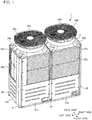
Fig. 1] Fig. 1 is a perspective view of an outdoor unit for an air-conditioning apparatus according toEmbodiment 1 of the present invention. - [
Fig. 2] Fig. 2 is a perspective view of the outdoor unit for an air-conditioning apparatus according toEmbodiment 1 of the present invention, illustrating an internal configuration thereof. - [
Fig. 3] Fig. 3 is a perspective view of one front heat-exchanger unit and two rear heat-exchanger units provided in the outdoor unit for an air-conditioning apparatus according toEmbodiment 1 of the present invention, illustrating the arrangement thereof. - [
Fig. 4] Fig. 4 is a top view of the one front heat-exchanger unit and the two rear heat-exchanger units provided in the outdoor unit for an air-conditioning apparatus according toEmbodiment 1 of the present invention, illustrating the arrangement thereof. - [
Fig. 5] Fig. 5 is a perspective view of the front heat-exchanger unit provided at the front of the outdoor unit for an air-conditioning apparatus according toEmbodiment 1 of the present invention. - [
Fig. 6] Fig. 6 is a perspective view of the rear heat-exchanger unit provided at the rear of the outdoor unit for an air-conditioning apparatus according toEmbodiment 1 of the present invention. - [
Fig. 7] Fig. 7 is a top view of two individual heat-exchanger units provided in an outdoor unit for an air-conditioning apparatus according to Embodiment 2 of the present invention, illustrating the arrangement thereof. - Embodiments of an outdoor unit for an air conditioning apparatus according to the present invention will now be described with reference to the drawings. The illustration in the drawings is only exemplary and does not limit the present invention. In the drawings, like reference numerals denote like or corresponding elements, which also applies to the entirety of this specification. The drawings are not necessarily to scale.
-
Fig. 1 is a perspective view of anoutdoor unit 1 for an air-conditioning apparatus according toEmbodiment 1 of the present invention. - As illustrated in
Fig. 1 , theoutdoor unit 1 includes acasing 11 on an outer periphery thereof. Thecasing 11 includes a front portion facing frontward, a left portion provided on a side of the front portion, a right portion provided on another side of the front portion and opposite the left portion, and a rear portion provided opposite the front portion. Thecasing 11 has a rectangular shape in plan view. - The
casing 11 is provided with a leftfront pillar 21 at a left front corner thereof in front view. Thecasing 11 is further provided with a leftrear pillar 23 at another corner thereof on the rear side of theleft front pillar 21 in front view. Thecasing 11 is further provided with a rightfront pillar 22 at a right front corner thereof in front view. Thecasing 11 is further provided with a right rear pillar, not illustrated, at yet another corner thereof on the rear side of the rightfront pillar 22 in front view. Thecasing 11 is further provided with afront center pillar 24 at the front center thereof. Thecasing 11 is further provided with a rear center pillar, not illustrated, at the rear center thereof. - The
left front pillar 21 and the rightfront pillar 22 are bridged by afront frame 25a at the upper ends thereof. Theleft front pillar 21 and the leftrear pillar 23 are bridged by aleft frame 26a at the upper ends thereof. The rightfront pillar 22 and the right rear pillar are bridged by a right frame, not illustrated, at the upper ends thereof. The leftrear pillar 23 and the right rear pillar are bridged by a rear frame, not illustrated, at the upper ends thereof. - The
casing 11 includes lowerfront panels front panels front panels casing 11. - The
casing 11 further includes a lowerleft panel 28a at the lower left thereof. Thecasing 11 further includes a lower right panel, not illustrated, at the lower right thereof. Thecasing 11 further includes a lower rear panel, not illustrated, at the lower rear thereof. The lowerleft panel 28a, the lower right panel, and the lower rear panel may also be removable or openable/closable, as with the lowerfront panels left panel 28a, the lower right panel, and the lower rear panel are removable or openable/closable when, for example, a worker maintains components provided in thecasing 11. - The
casing 11 hasair inlets casing 11 from theair inlets air inlet 32a provided in the front portion of thecasing 11 is surrounded by the leftfront pillar 21, the rightfront pillar 22, thefront frame 25a, and the lowerfront panels air inlet 32b provided in the left portion of thecasing 11 is surrounded by the leftfront pillar 21, the leftrear pillar 23, theleft frame 26a, and the lowerleft panel 28a. Likewise, the air inlets, not illustrated, are provided in the right portion and the rear portion, respectively, of thecasing 11. - The
casing 11 includes twotop panels top panel 29a has anair outlet 33a as an opening port for blowing air therefrom. Thetop panel 29b has anair outlet 33b as an opening port for blowing air therefrom. Thecasing 11 is provided with two air-sendingfans fans casing 11. The air-sendingfan 34a is provided below theair outlet 33a. The air-sendingfan 34b is provided below theair outlet 33b. - When the two air-sending
fans casing 11. Accordingly, air is taken in from theair inlets casing 11. The air thus taken into thecasing 11 is blown out by the two air-sendingfans air outlets - While the
casing 11 of theoutdoor unit 1 for an air-conditioning apparatus according toEmbodiment 1 has been described above, the present invention is not limited to such an embodiment. The configuration may be changed according to need. For example, another member may be added to thecasing 11. -
Fig. 2 is a perspective view of theoutdoor unit 1 for an air-conditioning apparatus according toEmbodiment 1 of the present invention, illustrating an internal configuration thereof. - As illustrated in
Fig. 2 , theoutdoor unit 1 includes aheat exchanger 50 enclosingair inlet spaces fans fans air inlet spaces heat exchanger 50. - The
heat exchanger 50 includes one front heat-exchanger unit 51 and two rear heat-exchanger units - The
heat exchanger 50 includes two parts each having a rectangular plan-view shape, with side faces thereof being present inside thecasing 11 and on the front side, the left side, the right side, and the rear side, respectively. The two rectangular parts of theheat exchanger 50 enclose the two respectiveair inlet spaces - The one front heat-
exchanger unit 51 has a straight plan-view shape extending along the front portion of thecasing 11. That is, the front heat-exchanger unit 51 has a continuous flat plate-like shape positioned on the front side of and extending over the twoair inlet spaces - The rear heat-
exchanger unit 52a is one of the heat exchanger units arranged in the lateral direction of thecasing 11 in plan view and each having a U shape having a side face 52a1 on the left side, a side face 52a3 on the right side, and a side face 52a2 on the rear side. The left and right side being continuous with the rear side, the continuous portions being bends of the heat exchanger. The rear heat-exchanger unit 52b is one of the heat exchanger units arranged in the lateral direction of thecasing 11 in plan view and each having a U shape having a side face 52b1 on the left side, a side face 52b3 on the right side, and a side face 52b2 on the rear side. The left and right side being continuous with the rear side, the continuous portions being bends of the heat exchanger. - Thus, the
air inlet spaces fans heat exchanger 50. - In addition, a
compressor 36 and a controller to serve a function of circulating the refrigerant through theoutdoor unit 1, and mechanical components such as an electric-device box 37 andpipes 38 are provided below the one front heat-exchanger unit 51 and the two rear heat-exchanger units - Considering the ease of maintenance or attaching of the
compressor 36 and the electric-device box 37, the front heat-exchanger unit 51 is positioned above thecompressor 36 and the electric-device box 37 so that thecompressor 36 and the electric-device box 37 are easily attachable or removable. Therefore, a hollow where theheat exchanger 50 is not present is provided at least at the lower front of thecasing 11, whereby a maintenance space for maintaining the mechanical components is provided. - The rear heat-
exchanger units exchanger unit 51 and are each positioned at the same level as the front heat-exchanger unit 51. That is, the rear heat-exchanger units compressor 36 and the electric-device box 37, as with the front heat-exchanger unit 51. -
Fig. 3 is a perspective view of the one front heat-exchanger unit 51 and the two rear heat-exchanger units outdoor unit 1 for an air-conditioning apparatus according toEmbodiment 1 of the present invention, illustrating the arrangement thereof. - As illustrated in
Fig. 3 , theair inlet spaces exchanger unit 51 and the two rear heat-exchanger units - The front heat-
exchanger unit 51 having a straight shape and is present on the front side of theair inlet spaces - The U-shaped rear heat-
exchanger unit 52a is present on the left side, the right side, and the rear side of theair inlet space 35a. The rear heat-exchanger unit 52a has bends continuous to the side faces 52a1 and 52a3 on the left and right sides, and the side face 52a2 on the rear side. - The U-shaped rear heat-
exchanger unit 52b is present on the left side, the right side, and the rear side of theair inlet space 35b. The rear heat-exchanger unit 52b has bends continuous to the side faces 52b1 and 52b3 on the left and right sides, and the side face 52b2 on the rear side. - The two rear heat-
exchanger units center line 60 passing through the center between the left portion and the right portion of thecasing 11. - The front heat-
exchanger unit 51 has a flat plate-like shape. Therefore, when the front side of theoutdoor unit 1 for an air-conditioning apparatus is desired to be opened at the time of maintenance or in any other like situation, the front heat-exchanger unit 51 is easily attachable or detachable. - The front heat-
exchanger unit 51 provided on the front side of thecasing 11 is positioned closer, than to other, to the right side of thecasing 11. Therefore, an open space extending vertically is provided on the front side of thecasing 11 and on a side opposite the side with which the front heat-exchanger unit 51 is aligned, that is, between the front heat-exchanger unit 51 and the rear heat-exchanger unit 52a. -
Fig. 4 is a top view of the one front heat-exchanger unit 51 and the two rear heat-exchanger units outdoor unit 1 for an air-conditioning apparatus according toEmbodiment 1 of the present invention, illustrating the arrangement thereof. - As illustrated in
Fig. 4 , the front heat-exchanger unit 51 and the rear heat-exchanger units view contours air inlet spaces view contours - In the
heat exchanger 50 forming the sides enclosing theair inlet spaces fans exchanger units casing 11 each have a smaller width than the other side faces 52a1, 52a2, 52b1, and 52b2. The widths of the side faces 52a3 and 52b3 of the rear heat-exchanger units heat exchanger 50. The widths of the side faces 52a3 and 52b3 of the rear heat-exchanger units exchanger units center line 61 in the depth direction of thecasing 11. - On the front side of the
casing 11, a pipe-connectingarea 70a where the front heat-exchanger unit 51 is connected to a pipe included in a refrigerant circuit is provided on the side opposite the right side with which the front heat-exchanger unit 51 is aligned. - Furthermore, a pipe-connecting
area 70b where one of the two rear heat-exchanger units exchanger unit 52a, is connected to a pipe included in the refrigerant circuit is provided on the left side of thecasing 11 and adjacent to the pipe-connectingarea 70a for the front heat-exchanger unit 51. - The pipe-connecting
area 70a and the pipe-connectingarea 70b are provided adjacent to each other, thereby forming a pipe-connectingarea 70 for the front heat-exchanger unit 51 and the rear heat-exchanger unit 52a. The pipe-connectingarea 70 is provided in an open space at the front left, considering the ease of maintenance and attaching. - The pipe-connecting
area 70 may alternatively be provided at the front right with the front heat-exchanger unit 51 positioned closer, than to other, to the left side. In that case, the pipe-connecting area provided in an open space serves as a pipe-connecting area for the front heat-exchanger unit 51 and the rear heat-exchanger unit 52a. - A pipe-connecting
area 71 where the other of the two rear heat-exchanger units exchanger unit 52b, is connected to a pipe included in the refrigerant circuit is provided in the laterally central area of thecasing 11. The pipe-connectingarea 71 for the rear heat-exchanger unit 52b is provided in the central area and on the front side with respect to thecenter line 61 in the depth direction of thecasing 11, so that the pipe can be maintained and connected by being accessed from the lower front of thecasing 11. The pipe-connectingarea 71 for the rear heat-exchanger unit 52b is not provided on the right side of thecasing 11, because the electric-device box 37 is obstructive, and the length of the pipe to be led from thecompressor 36 becomes long. - The position of the pipe-connecting
area 71 may be on the rear side with respect to thecenter line 61 in the depth direction of thecasing 11, as long as the pipes are maintainable and connectable. -
Fig. 5 is a perspective view of the front heat-exchanger unit 51 provided at the front of theoutdoor unit 1 for an air-conditioning apparatus according toEmbodiment 1 of the present invention.Fig. 6 is a perspective view of the rear heat-exchanger unit 52b provided at the rear of theoutdoor unit 1 for an air-conditioning apparatus according toEmbodiment 1 of the present invention. - The one front heat-
exchanger unit 51 and the two rear heat-exchanger units exchanger units exchanger unit 51. That is, awidth 53 of the front heat-exchanger unit 51 is equal to aperipheral length 54 that is the sum of the widths of the side faces 52a1, 52a2, and 52a3 or the side faces 52b1, 52b2, and 52b3 of a corresponding one of the two folded rear heat-exchanger units vertical length 55 of the front heat-exchanger unit 51 is equal to avertical length 56 of each of the two rear heat-exchanger units exchanger unit 51 and the two rear heat-exchanger units - Thus, the one front heat-
exchanger unit 51 and the two rear heat-exchanger units exchanger unit 51 and the two rear heat-exchanger units - According to
Embodiment 1, the four sides, that is, the front portion, the left portion, the right portion, and the rear portion, of thecasing 11 having a rectangular plan-view shape are covered by theheat exchanger 50, and the rear heat-exchanger units casing 11 between the left portion and the right portion. Hence, the side faces of theheat exchanger 50 to which air is to be fed are present along the four respective sides of each of the twoair inlet spaces heat exchanger 50 is maximized. - For comparison, in the technique according to
Patent Literature 1, two L-shaped heat-exchanger units are arranged along the side faces of the casing. Such an arrangement of the heat-exchanger units tends to be restricted in terms of the width and the depth of the casing. Therefore, the capacity of the heat exchanger cannot be maximized. - According to
Embodiment 1, theheat exchanger 50 is present on the four sides of each of theair inlet spaces view contours fans heat exchanger 50 can be maximized. - Specifically, according to
Embodiment 1, theoutdoor unit 1 for an air-conditioning apparatus includes thecasing 11 having a rectangular plan-view shape formed of the front portion, the left portion provided on a side of the front portion, the right portion provided opposite the left portion, and the rear portion provided opposite the front portion. Theoutdoor unit 1 for an air-conditioning apparatus includes, in thecasing 11 thereof, theheat exchanger 50 including two parts each having a rectangular plan-view shape, with the side faces thereof being present on the front side, the left side, the right side, and the rear side, respectively, of thecasing 11. Theoutdoor unit 1 for an air-conditioning apparatus further includes the two air-sendingfans air inlet spaces heat exchanger 50. - In such a configuration, the heat-
exchanger units heat exchanger 50 has a further increased capacity in a casing of a limited size while the volume of air to be fed to theheat exchanger 50 is maximized. - Furthermore, according to
Embodiment 1, theheat exchanger 50 includes one front heat-exchanger unit 51 and two rear heat-exchanger units exchanger unit 51 and the two rear heat-exchanger units - In such a configuration, since heat-exchanger units of the same capacity are employed, no drift currents occur in the refrigerant flowing in the
heat exchanger 50. Accordingly, the refrigerant can be efficiently distributed over theheat exchanger 50, and a simple refrigerant circuit can be realized. Consequently, the product cost can be reduced. Moreover, since the heat-exchanger units of the same kind can be manufactured through a common manufacturing process, productivity can be improved. - For comparison, in the technique according to Patent Literature 2, one U-shaped heat-exchanger unit and one flat heat-exchanger unit are combined, and the two heat-exchanger units have different capacities. Therefore, the technique has a problem in that effective performance cannot be obtained unless the amount of refrigerant to be fed into the U-shaped heat-exchanger unit and the amount of refrigerant to be fed into the flat heat-exchanger unit are well balanced with each other. Such a configuration may require a structure that increases the product cost. For example, a linear expansion valve may need to be added to each of the heat-exchanger units. That is, the product cost cannot be reduced.
- According to
Embodiment 1, theheat exchanger 50 includes two units that are arranged in parallel in the lateral direction of thecasing 11 in plan view. In theheat exchanger 50, the widths of the side faces 52a3 and 52b3 that are present in the laterally central area of thecasing 11 are smaller than the widths of the other side faces 52a1, 52a2, 52b1, and 52b2. - In such a configuration, the volume of air to be fed to the
heat exchanger 50 can be maximized even with the side faces 52a3 and 52b3 that are present in the laterally central area of theheat exchanger 50. The widths of the side faces 52a3 and 52b3 that are present in the laterally central area of theheat exchanger 50 are smaller than the widths of the other side faces. Such a configuration suppresses the increase in the product cost that may occur if theheat exchanger 50 is designed excessively long to extend into an area where no air is fed, making no contribution to the performance. Moreover, the pipe-connectingarea 71 can be provided on the front side of the side faces 52a3 and 52b3 that are present in the laterally central area of theheat exchanger 50. Consequently, the ease of maintenance and attaching can be improved. - According to
Embodiment 1, the one front heat-exchanger unit 51 having a straight shape extending along the front portion of thecasing 11 in plan view is provided as a heat-exchanger unit. The two rear heat-exchanger units casing 11 in plan view and each having a shape having the side faces 52a1, 52a2, and 52a3 or 52b1, 52b2, and 52b3 on the left side, the right side, and the rear side, respectively, are provided as heat-exchanger units. The left and right side being continuous with the rear side, the continuous portions being bends of the heat exchanger. - In such a configuration, the
heat exchanger 50 provided in thecasing 11 can have two parts each having a rectangular plan-view shape with the side faces thereof being present on the front side, the left side, the right side, and the rear side, respectively, of thecasing 11. - According to
Embodiment 1, the two rear heat-exchanger units center line 60 passing through the center between the left portion and the right portion of thecasing 11. - In such a configuration, the two air-sending
fans heat exchanger 50 does not become uneven, that is, the distribution is balanced between the left side and the right side. - According to
Embodiment 1, the front heat-exchanger unit 51 provided on the front side of thecasing 11 is positioned closer, than to other, to the right side of thecasing 11. On the front side of thecasing 11, the pipe-connectingarea 70a where the front heat-exchanger unit 51 is connected to the pipe included in the refrigerant circuit is provided on the left side opposite the side with which the front heat-exchanger unit 51 is aligned. - In such a configuration, the pipe-connecting
area 70a for the front heat-exchanger unit 51 can be provided on the front side, not interfering with the mechanical components. Therefore, the worker can work easily, and the ease of maintenance and attaching can be improved. - According to
Embodiment 1, the pipe-connectingarea 70b where one of the two rear heat-exchanger units exchanger unit 52a, is connected to the pipe included in the refrigerant circuit is provided on the left side of thecasing 11 and adjacent to the pipe-connectingarea 70a for the front heat-exchanger unit 51. The pipe-connectingarea 71 where the other of the two rear heat-exchanger units exchanger unit 52b, is connected to the pipe included in the refrigerant circuit is provided in the laterally central area of thecasing 11. - In such a configuration, the pipe-connecting
area 70b for the one rear heat-exchanger unit 52a can be provided on the front side, not interfering with the mechanical components. Therefore, the worker can work easily, and the ease of maintenance and attaching can be improved. In addition, since the pipe-connectingarea 70b for the one rear heat-exchanger unit 52a is provided adjacent to the pipe-connectingarea 70a for the front heat-exchanger unit 51, a wide pipe-connectingarea 70 is provided. Therefore, the worker can work easily, and the ease of maintenance and attaching can be improved. Furthermore, the pipe-connectingarea 71 for the other rear heat-exchanger unit 52b is solely provided in the laterally central area of thecasing 11. Therefore, a satisfactory work space for the worker is provided. Accordingly, the worker can work easily, and the ease of maintenance and attaching can be improved. - According to
Embodiment 1, a maintenance space for maintaining the mechanical components is provided at least at the lower front of thecasing 11. - Specifically, the lower end of the front heat-
exchanger unit 51 is positioned above the mechanical components such as thecompressor 36 and the electric-device box 37, whereby the maintenance space is provided. Therefore, the ease of maintenance and attaching of the mechanical components such as thecompressor 36 and the electric-device box 37 is not reduced. Thus, the maintenance space of the maximum size can be provided at the lower front of theheat exchanger 50. - In such a configuration, since the space for maintaining the mechanical components is provided in a space where the
heat exchanger 50 is not present, a satisfactory size of a work space is provided for the worker. Therefore, the worker can work easily, and the ease of maintenance and attaching can be improved. - For comparison, in the technique according to Patent Literature 3, pipe areas are concentrated in a front central area of the outdoor unit for an air-conditioning apparatus, and there are not enough room, on the front side, for providing a space for maintaining the mechanical components. Therefore, the ease of maintenance and attaching is reduced.
- The basic configuration of an
outdoor unit 1 for an air-conditioning apparatus according to Embodiment 2 is the same as that of theoutdoor unit 1 for an air-conditioning apparatus according toEmbodiment 1. Therefore, Embodiment 2 will be described focusing on a difference fromEmbodiment 1. - The difference between
Embodiment 1 and Embodiment 2 is the arrangement of a plurality of heat-exchanger units included in theoutdoor unit 1 for an air-conditioning apparatus. InEmbodiment 1, three heat-exchanger units exchanger units -
Fig. 7 is a top view of two individual heat-exchanger units outdoor unit 1 for an air-conditioning apparatus according to Embodiment 2 of the present invention, illustrating the arrangement thereof. - The
heat exchanger 50 includes the two individual heat-exchanger units - The individual heat-
exchanger unit 57a is arranged in parallel with the individual heat-exchanger unit 57b in the lateral direction of thecasing 11 in plan view and having a shape having side faces on the front side, the left side, the right side, and the rear side, respectively. The left and right side being continuous with the rear side, the continuous portions being bends of the heat exchanger. The individual heat-exchanger unit 57a has a side face 57a1 on the front side, a side face 57a2 on the left side, a side face 57a4 on the right side, and a side face 57a3 on the rear side. The left and right side being continuous with the rear side, the continuous portions being bends of the heat exchanger. - The individual heat-
exchanger unit 57b is arranged in parallel with the individual heat-exchanger unit 57a in the lateral direction of thecasing 11 in plan view and having a shape having side faces on the front side, the left side, the right side, and the rear side, respectively. The individual heat-exchanger unit 57b has a side face 57b1 on the front side, a side face 57b2 on the left side, a side face 57b4 on the right side, and a side face 57b3 on the rear side. - The two individual heat-
exchanger units center line 60 passing through the center between the left portion and the right portion of thecasing 11. The two individual heat-exchanger units - Pipe-connecting
areas exchanger units casing 11. The pipe-connectingareas exchanger units center line 61 in the depth direction of thecasing 11, so that the pipes can be easily maintained. - According to Embodiment 2, the two individual heat-
exchanger units casing 11 in plan view and respectively having a shape having the side faces 57a1, 57a2, 57a4, and 57a3 on the front side, the left side, the right side, and the rear side, respectively, and a shape having side faces 57b1, 57b2, 57b4, and 57b3 on the front side, the left side, the right side, and the rear side, respectively, are provided as heat-exchanger units. The left and right sides being continuous with the rear sides, the continuous portions being bends of the heat exchanger. - In such a configuration, the
heat exchanger 50 provided in thecasing 11 can have two parts each having a rectangular plan-view shape with the side faces thereof being present on the front side, the left side, the right side, and the rear side, respectively, of thecasing 11. - According to Embodiment 2, the two individual heat-
exchanger units center line 60 passing through the center between the left portion and the right portion of thecasing 11. - In such a configuration, the two air-sending
fans heat exchanger 50 does not become uneven, that is, the distribution is balanced between the left side and the right side. - According to Embodiment 2, the pipe-connecting
areas exchanger units casing 11. - In such a configuration, the volume of air to be fed to the
heat exchanger 50 can be maximized even with the side faces 57a4 and 57b4 that are present in the laterally central area of theheat exchanger 50. The widths of the side faces 57a4 and 57b4 that are present in the laterally central area of theheat exchanger 50 are smaller than the widths of the other side faces. Such a configuration suppresses the increase in the product cost that may occur if theheat exchanger 50 is designed excessively long to extend into an area where no air is fed, making no contribution to the performance. Moreover, the pipe-connectingareas heat exchanger 50. Consequently, the ease of maintenance and attaching can be improved. - According to Embodiment 2, the number of individual components can be reduced to two each for the respective heat-
exchanger units - While
Embodiments 1 and 2 have been described above, the present invention is not limited thereto. For example, all or some of the features of the embodiments may be combined. - While
Embodiments 1 and 2 each concern a configuration in which two air-sending fans are provided in one casing, the present invention is not limited to such a configuration. For example, three or more air-sending fans may be provided in parallel in one casing. Furthermore, the heat exchanger may be provided in such a manner as to enclose air inlet spaces provided below the three or more air-sending fans, respectively, and to extend along the four sides of each of the air inlet spaces, whereby the air inlet spaces each have a rectangular plan-view shape. Reference Signs List - 1
outdoor unit 11casing 21 leftfront pillar 22 rightfront pillar 23 leftrear pillar 24front center pillar 25a front frame 26a leftframe 27a lowerfront panel 27b lowerfront panel 28a lowerleft panel 29atop panel 29btop panel 32a air inlet 32b air inlet 33a air outlet 33b air outlet 34a air-sendingfan 34b air-sendingfan 35aair inlet space 35bair inlet space 36compressor 37 electric-device box 38pipe 39a fan top-view contour 39b fan top-view contour 50heat exchanger 51 front heat-exchanger unit 52a rear heat-exchanger unit 52a1 side face 52a2 side face 52a3side face 52b rear heat-exchanger unit 52b1 side face 52b2 side face 52b3 side face 53width 54peripheral length 55vertical length 56vertical length 57a individual heat-exchanger unit 57a1 side face 57a2 side face 57a3 side face 57a4side face 57b individual heat-exchanger unit 57b1 side face 57b2 side face 57b3 side face 57b4 side face 60center line 61center line 70 pipe-connectingarea 70a pipe-connectingarea 70b pipe-connectingarea 71 pipe-connectingarea 72 pipe-connectingarea 73 pipe-connecting area
Claims (11)
- An outdoor unit for an air-conditioning apparatus, the outdoor unit comprising:a casing having a rectangular plan-view shape formed of a front portion, a left portion provided on a side of the front portion, a right portion provided opposite the left portion, and a rear portion provided opposite the front portion;a heat exchanger provided in the casing and including a plurality of parts each having a rectangular plan-view shape with side faces being present on a front side, a left side, a right side, and a rear side, respectively, of the casing; anda plurality of air-sending fans provided above a plurality of air inlet spaces, respectively, the air inlet spaces each being provided on an inner side of a corresponding one of the plurality of rectangular parts of the heat exchanger.
- The outdoor unit for an air-conditioning apparatus of claim 1,
wherein the heat exchanger includes a plurality of heat-exchanger units, and
wherein the plurality of heat-exchanger units have a same capacity. - The outdoor unit for an air-conditioning apparatus of claim 1 or 2, wherein the heat exchanger comprises two heat exchangers that are arranged in parallel in a lateral direction of the casing in plan view, and widths of the side faces that are present in a laterally central area of the casing are smaller than widths of the other side faces.
- The outdoor unit for an air-conditioning apparatus of claim 3, wherein the plurality of heat-exchanger units comprise one front heat-exchanger unit having a straight plan-view shape extending along the front portion of the casing, and two rear heat-exchanger units arranged in the lateral direction of the casing in plan view and each having a shape having side faces on a left side, a right side, and a rear side, the left and right side being continuous with the rear side, the continuous portions being bends of the heat exchanger.
- The outdoor unit for an air-conditioning apparatus of claim 4, wherein the two rear heat-exchanger units are shaped line symmetrically with respect to a center line passing through a center between the left portion and the right portion of the casing.
- The outdoor unit for an air-conditioning apparatus of claim 4 or 5,
wherein the front heat-exchanger unit provided on the front side of the casing is positioned closer, than to an other, to one lateral side, and
wherein a pipe-connecting area where the front heat-exchanger unit is connected to a pipe included in a refrigerant circuit is provided on the front side of the casing and on the other lateral side. - The outdoor unit for an air-conditioning apparatus of claim 6,
wherein a pipe-connecting area where one of the two rear heat-exchanger units is connected to a pipe included in the refrigerant circuit is provided on one of the left side and the right side of the casing and adjacent to the pipe-connecting area for the front heat-exchanger unit, and
wherein a pipe-connecting area where an other of the two rear heat-exchanger units is connected to a pipe included in the refrigerant circuit is provided in a laterally central area of the casing. - The outdoor unit for an air-conditioning apparatus of claim 3, wherein the plurality of heat-exchanger units comprise two individual heat-exchanger units arranged in parallel in the lateral direction of the casing in plan view and each having a shape having side faces on a front side, a left side, a right side, and a rear side, the left and right side being continuous with the rear side, the continuous portions being bends of the heat exchanger.
- The outdoor unit for an air-conditioning apparatus of claim 8, wherein the two individual heat-exchanger units are shaped line symmetrically with respect to a center line passing through a center between the left portion and the right portion of the casing.
- The outdoor unit for an air-conditioning apparatus of claim 8 or 9, wherein a pipe-connecting area where the two individual heat-exchanger units are connected to respective pipes included in the refrigerant circuit is provided in a center between the left portion and the right portion of the casing.
- The outdoor unit for an air-conditioning apparatus of any one of claims 1 to 10, wherein a maintenance space for maintaining a mechanical component is provided at least in a lower front part of the casing.
Applications Claiming Priority (1)
| Application Number | Priority Date | Filing Date | Title |
|---|---|---|---|
| PCT/JP2016/064622 WO2017199339A1 (en) | 2016-05-17 | 2016-05-17 | Outdoor unit for air conditioning device |
Publications (3)
| Publication Number | Publication Date |
|---|---|
| EP3460344A1 true EP3460344A1 (en) | 2019-03-27 |
| EP3460344A4 EP3460344A4 (en) | 2019-05-08 |
| EP3460344B1 EP3460344B1 (en) | 2024-02-28 |
Family
ID=60324987
Family Applications (1)
| Application Number | Title | Priority Date | Filing Date |
|---|---|---|---|
| EP16902359.5A Active EP3460344B1 (en) | 2016-05-17 | 2016-05-17 | Outdoor unit for air conditioning device |
Country Status (5)
| Country | Link |
|---|---|
| US (1) | US10837656B2 (en) |
| EP (1) | EP3460344B1 (en) |
| JP (1) | JP6628871B2 (en) |
| CN (1) | CN109196283A (en) |
| WO (1) | WO2017199339A1 (en) |
Families Citing this family (11)
| Publication number | Priority date | Publication date | Assignee | Title |
|---|---|---|---|---|
| JP6269717B2 (en) * | 2016-04-21 | 2018-01-31 | ダイキン工業株式会社 | Heat source unit |
| JP6414265B2 (en) * | 2017-03-30 | 2018-10-31 | ダイキン工業株式会社 | Refrigeration unit heat source unit |
| CN207922420U (en) * | 2018-01-16 | 2018-09-28 | 广东美的暖通设备有限公司 | Central air-conditioning outdoor unit and central air-conditioning with it |
| JP6907964B2 (en) * | 2018-01-31 | 2021-07-21 | ダイキン工業株式会社 | Outdoor unit of air conditioner |
| USD998769S1 (en) * | 2019-08-06 | 2023-09-12 | Mitsubishi Electric Corporation | Chiller unit |
| JP7346181B2 (en) * | 2019-09-11 | 2023-09-19 | 東芝キヤリア株式会社 | heat source device |
| USD940843S1 (en) * | 2019-10-22 | 2022-01-11 | Mitsubishi Electric Corporation | Outdoor unit for air conditioner |
| WO2021134902A1 (en) * | 2019-12-31 | 2021-07-08 | 广东美的制冷设备有限公司 | Air conditioner |
| JP1715459S (en) | 2021-08-30 | 2022-05-19 | Chiller unit | |
| US20230076784A1 (en) * | 2021-09-06 | 2023-03-09 | Inventec (Pudong) Technology Corporation | Heat dissipation assembly and electronic assembly |
| JPWO2023218555A1 (en) * | 2022-05-11 | 2023-11-16 |
Family Cites Families (26)
| Publication number | Priority date | Publication date | Assignee | Title |
|---|---|---|---|---|
| JPS583186B2 (en) * | 1978-08-07 | 1983-01-20 | 三洋電機株式会社 | Outdoor unit of separate air conditioner |
| JPS6086872U (en) * | 1983-11-19 | 1985-06-14 | 三菱重工業株式会社 | Air conditioner outdoor unit |
| JP3710874B2 (en) | 1996-02-23 | 2005-10-26 | 三洋電機株式会社 | Air conditioner outdoor unit |
| US5832733A (en) | 1996-02-23 | 1998-11-10 | Sanyo Electric Co., Ltd | Power controllable type air conditioner |
| JPH10141708A (en) * | 1996-11-12 | 1998-05-29 | Matsushita Electric Ind Co Ltd | Outdoor unit of air conditioner |
| JP4183053B2 (en) * | 2000-01-14 | 2008-11-19 | 東芝キヤリア株式会社 | Air conditioner outdoor unit |
| AU2548601A (en) | 2000-01-14 | 2001-07-24 | Toshiba Carrier Corporation | Outdoor unit of air conditioner |
| JP3846325B2 (en) | 2002-02-07 | 2006-11-15 | ダイキン工業株式会社 | Air conditioner outdoor unit |
| JP2003240276A (en) | 2002-02-13 | 2003-08-27 | Daikin Ind Ltd | Outdoor unit for air conditioner |
| JP4261109B2 (en) * | 2002-02-13 | 2009-04-30 | ダイキン工業株式会社 | Air conditioner outdoor unit |
| JP3714264B2 (en) * | 2002-02-28 | 2005-11-09 | ダイキン工業株式会社 | Air conditioner outdoor unit |
| JP2003279076A (en) | 2002-03-20 | 2003-10-02 | Sanyo Electric Co Ltd | Outdoor unit of air-conditioner |
| JP2004340504A (en) * | 2003-05-16 | 2004-12-02 | Mitsubishi Heavy Ind Ltd | Outdoor unit for air conditioning and air conditioner comprising the same |
| US20070163295A1 (en) * | 2006-01-18 | 2007-07-19 | Martin Lendell Sr | Air treatment systems |
| JP5159158B2 (en) | 2007-05-08 | 2013-03-06 | 株式会社Access | Execution environment software, presence information providing program, terminal device, and presence management system |
| JP2008292068A (en) * | 2007-05-25 | 2008-12-04 | Fujitsu General Ltd | Air conditioner outdoor unit |
| US20090084131A1 (en) * | 2007-10-01 | 2009-04-02 | Nordyne Inc. | Air Conditioning Units with Modular Heat Exchangers, Inventories, Buildings, and Methods |
| US8146373B2 (en) * | 2008-03-10 | 2012-04-03 | Snow Iii Amos A | Accessory sub-cooling unit and method of use |
| EP2354683A3 (en) * | 2010-01-28 | 2013-04-17 | Sanyo Electric Co., Ltd. | Outdoor unit for air conditioner |
| US9273896B2 (en) * | 2011-05-20 | 2016-03-01 | Daikin Industries, Ltd. | Outdoor unit of refrigerating apparatus |
| EP2799786A4 (en) * | 2011-12-26 | 2015-08-26 | Mitsubishi Electric Corp | OUTDOOR UNIT AND AIR CONDITIONER |
| CN102679463A (en) * | 2012-03-14 | 2012-09-19 | 美的集团有限公司 | Outdoor unit of direct-current variable-frequency multi-connected air conditioner |
| CN202792704U (en) * | 2012-08-17 | 2013-03-13 | 广东美的电器股份有限公司 | Air-side heat exchanger, air-cooled heat pump unit and air-conditioning system |
| CN104704304B (en) * | 2012-10-02 | 2016-06-29 | 三菱电机株式会社 | freezer |
| CN204963023U (en) * | 2015-09-30 | 2016-01-13 | 宁波奥克斯电气有限公司 | Big volume air condensing units |
| CN105258243A (en) * | 2015-10-14 | 2016-01-20 | 珠海格力电器股份有限公司 | Outdoor unit of air conditioner |
-
2016
- 2016-05-17 CN CN201680085623.0A patent/CN109196283A/en active Pending
- 2016-05-17 WO PCT/JP2016/064622 patent/WO2017199339A1/en not_active Ceased
- 2016-05-17 EP EP16902359.5A patent/EP3460344B1/en active Active
- 2016-05-17 US US16/080,518 patent/US10837656B2/en active Active
- 2016-05-17 JP JP2018517972A patent/JP6628871B2/en active Active
Also Published As
| Publication number | Publication date |
|---|---|
| EP3460344B1 (en) | 2024-02-28 |
| WO2017199339A1 (en) | 2017-11-23 |
| US10837656B2 (en) | 2020-11-17 |
| US20190072285A1 (en) | 2019-03-07 |
| JPWO2017199339A1 (en) | 2018-11-29 |
| CN109196283A (en) | 2019-01-11 |
| EP3460344A4 (en) | 2019-05-08 |
| JP6628871B2 (en) | 2020-01-15 |
Similar Documents
| Publication | Publication Date | Title |
|---|---|---|
| EP3460344B1 (en) | Outdoor unit for air conditioning device | |
| JP5587060B2 (en) | Built-in air conditioner | |
| EP2023048B1 (en) | Air conditioner having electrical equipment box cooling mechanism | |
| EP2056029B1 (en) | Air conditioner | |
| EP0985889B1 (en) | Ceiling embedded type indoor unit | |
| US11162693B2 (en) | Fan unit, and outdoor unit of air conditioner comprising fan unit | |
| EP2827071A1 (en) | Bidirectional-blow-out, ceiling-embedded air conditioner | |
| US10240805B2 (en) | Indoor unit for air conditioner | |
| JP6126447B2 (en) | Air conditioner | |
| JP5855707B2 (en) | Air conditioning system | |
| EP3048375B1 (en) | Air conditioner | |
| US10047963B2 (en) | Indoor unit for air-conditioning apparatus | |
| EP3961111B1 (en) | Ceiling-embedded indoor unit and air-conditioning device | |
| EP3130860B1 (en) | Air conditioner | |
| KR102137462B1 (en) | Outdoor unit of air conditioner | |
| US11333367B2 (en) | HVACR system including multi-positional and multi-use plenum fans | |
| CN205980042U (en) | Send many spaces of formula air conditioning interior machine under inclining back | |
| WO2019116838A1 (en) | Heat exchange unit and air conditioning device having same mounted therein | |
| JP6658779B2 (en) | Heat exchange equipment | |
| EP3086051A1 (en) | Air conditioner | |
| JP2013113517A (en) | Heat exchanger, and outdoor unit for air conditioner | |
| JP2023087878A (en) | indoor unit of air conditioner | |
| JP2015132424A (en) | Air conditioner indoor unit |
Legal Events
| Date | Code | Title | Description |
|---|---|---|---|
| STAA | Information on the status of an ep patent application or granted ep patent |
Free format text: STATUS: THE INTERNATIONAL PUBLICATION HAS BEEN MADE |
|
| PUAI | Public reference made under article 153(3) epc to a published international application that has entered the european phase |
Free format text: ORIGINAL CODE: 0009012 |
|
| STAA | Information on the status of an ep patent application or granted ep patent |
Free format text: STATUS: REQUEST FOR EXAMINATION WAS MADE |
|
| 17P | Request for examination filed |
Effective date: 20181019 |
|
| AK | Designated contracting states |
Kind code of ref document: A1 Designated state(s): AL AT BE BG CH CY CZ DE DK EE ES FI FR GB GR HR HU IE IS IT LI LT LU LV MC MK MT NL NO PL PT RO RS SE SI SK SM TR |
|
| AX | Request for extension of the european patent |
Extension state: BA ME |
|
| A4 | Supplementary search report drawn up and despatched |
Effective date: 20190409 |
|
| RIC1 | Information provided on ipc code assigned before grant |
Ipc: F24F 1/16 20110101AFI20190403BHEP Ipc: F24F 1/18 20110101ALI20190403BHEP Ipc: F24F 1/56 20110101ALI20190403BHEP Ipc: F24F 1/50 20110101ALI20190403BHEP |
|
| DAV | Request for validation of the european patent (deleted) | ||
| DAX | Request for extension of the european patent (deleted) | ||
| STAA | Information on the status of an ep patent application or granted ep patent |
Free format text: STATUS: EXAMINATION IS IN PROGRESS |
|
| 17Q | First examination report despatched |
Effective date: 20200422 |
|
| GRAP | Despatch of communication of intention to grant a patent |
Free format text: ORIGINAL CODE: EPIDOSNIGR1 |
|
| STAA | Information on the status of an ep patent application or granted ep patent |
Free format text: STATUS: GRANT OF PATENT IS INTENDED |
|
| INTG | Intention to grant announced |
Effective date: 20231026 |
|
| GRAS | Grant fee paid |
Free format text: ORIGINAL CODE: EPIDOSNIGR3 |
|
| GRAA | (expected) grant |
Free format text: ORIGINAL CODE: 0009210 |
|
| STAA | Information on the status of an ep patent application or granted ep patent |
Free format text: STATUS: THE PATENT HAS BEEN GRANTED |
|
| AK | Designated contracting states |
Kind code of ref document: B1 Designated state(s): AL AT BE BG CH CY CZ DE DK EE ES FI FR GB GR HR HU IE IS IT LI LT LU LV MC MK MT NL NO PL PT RO RS SE SI SK SM TR |
|
| REG | Reference to a national code |
Ref country code: GB Ref legal event code: FG4D |
|
| REG | Reference to a national code |
Ref country code: CH Ref legal event code: EP |
|
| P01 | Opt-out of the competence of the unified patent court (upc) registered |
Effective date: 20240205 |
|
| REG | Reference to a national code |
Ref country code: DE Ref legal event code: R096 Ref document number: 602016086093 Country of ref document: DE |
|
| REG | Reference to a national code |
Ref country code: IE Ref legal event code: FG4D |
|
| REG | Reference to a national code |
Ref country code: LT Ref legal event code: MG9D |
|
| PG25 | Lapsed in a contracting state [announced via postgrant information from national office to epo] |
Ref country code: IS Free format text: LAPSE BECAUSE OF FAILURE TO SUBMIT A TRANSLATION OF THE DESCRIPTION OR TO PAY THE FEE WITHIN THE PRESCRIBED TIME-LIMIT Effective date: 20240628 |
|
| REG | Reference to a national code |
Ref country code: NL Ref legal event code: MP Effective date: 20240228 |
|
| PG25 | Lapsed in a contracting state [announced via postgrant information from national office to epo] |
Ref country code: LT Free format text: LAPSE BECAUSE OF FAILURE TO SUBMIT A TRANSLATION OF THE DESCRIPTION OR TO PAY THE FEE WITHIN THE PRESCRIBED TIME-LIMIT Effective date: 20240228 |
|
| PG25 | Lapsed in a contracting state [announced via postgrant information from national office to epo] |
Ref country code: GR Free format text: LAPSE BECAUSE OF FAILURE TO SUBMIT A TRANSLATION OF THE DESCRIPTION OR TO PAY THE FEE WITHIN THE PRESCRIBED TIME-LIMIT Effective date: 20240529 |
|
| PG25 | Lapsed in a contracting state [announced via postgrant information from national office to epo] |
Ref country code: RS Free format text: LAPSE BECAUSE OF FAILURE TO SUBMIT A TRANSLATION OF THE DESCRIPTION OR TO PAY THE FEE WITHIN THE PRESCRIBED TIME-LIMIT Effective date: 20240528 Ref country code: HR Free format text: LAPSE BECAUSE OF FAILURE TO SUBMIT A TRANSLATION OF THE DESCRIPTION OR TO PAY THE FEE WITHIN THE PRESCRIBED TIME-LIMIT Effective date: 20240228 Ref country code: NL Free format text: LAPSE BECAUSE OF FAILURE TO SUBMIT A TRANSLATION OF THE DESCRIPTION OR TO PAY THE FEE WITHIN THE PRESCRIBED TIME-LIMIT Effective date: 20240228 |
|
| PG25 | Lapsed in a contracting state [announced via postgrant information from national office to epo] |
Ref country code: ES Free format text: LAPSE BECAUSE OF FAILURE TO SUBMIT A TRANSLATION OF THE DESCRIPTION OR TO PAY THE FEE WITHIN THE PRESCRIBED TIME-LIMIT Effective date: 20240228 |
|
| PG25 | Lapsed in a contracting state [announced via postgrant information from national office to epo] |
Ref country code: RS Free format text: LAPSE BECAUSE OF FAILURE TO SUBMIT A TRANSLATION OF THE DESCRIPTION OR TO PAY THE FEE WITHIN THE PRESCRIBED TIME-LIMIT Effective date: 20240528 Ref country code: NO Free format text: LAPSE BECAUSE OF FAILURE TO SUBMIT A TRANSLATION OF THE DESCRIPTION OR TO PAY THE FEE WITHIN THE PRESCRIBED TIME-LIMIT Effective date: 20240528 Ref country code: NL Free format text: LAPSE BECAUSE OF FAILURE TO SUBMIT A TRANSLATION OF THE DESCRIPTION OR TO PAY THE FEE WITHIN THE PRESCRIBED TIME-LIMIT Effective date: 20240228 Ref country code: LT Free format text: LAPSE BECAUSE OF FAILURE TO SUBMIT A TRANSLATION OF THE DESCRIPTION OR TO PAY THE FEE WITHIN THE PRESCRIBED TIME-LIMIT Effective date: 20240228 Ref country code: IS Free format text: LAPSE BECAUSE OF FAILURE TO SUBMIT A TRANSLATION OF THE DESCRIPTION OR TO PAY THE FEE WITHIN THE PRESCRIBED TIME-LIMIT Effective date: 20240628 Ref country code: HR Free format text: LAPSE BECAUSE OF FAILURE TO SUBMIT A TRANSLATION OF THE DESCRIPTION OR TO PAY THE FEE WITHIN THE PRESCRIBED TIME-LIMIT Effective date: 20240228 Ref country code: GR Free format text: LAPSE BECAUSE OF FAILURE TO SUBMIT A TRANSLATION OF THE DESCRIPTION OR TO PAY THE FEE WITHIN THE PRESCRIBED TIME-LIMIT Effective date: 20240529 Ref country code: FI Free format text: LAPSE BECAUSE OF FAILURE TO SUBMIT A TRANSLATION OF THE DESCRIPTION OR TO PAY THE FEE WITHIN THE PRESCRIBED TIME-LIMIT Effective date: 20240228 Ref country code: ES Free format text: LAPSE BECAUSE OF FAILURE TO SUBMIT A TRANSLATION OF THE DESCRIPTION OR TO PAY THE FEE WITHIN THE PRESCRIBED TIME-LIMIT Effective date: 20240228 Ref country code: BG Free format text: LAPSE BECAUSE OF FAILURE TO SUBMIT A TRANSLATION OF THE DESCRIPTION OR TO PAY THE FEE WITHIN THE PRESCRIBED TIME-LIMIT Effective date: 20240228 |
|
| PG25 | Lapsed in a contracting state [announced via postgrant information from national office to epo] |
Ref country code: PT Free format text: LAPSE BECAUSE OF FAILURE TO SUBMIT A TRANSLATION OF THE DESCRIPTION OR TO PAY THE FEE WITHIN THE PRESCRIBED TIME-LIMIT Effective date: 20240628 Ref country code: PL Free format text: LAPSE BECAUSE OF FAILURE TO SUBMIT A TRANSLATION OF THE DESCRIPTION OR TO PAY THE FEE WITHIN THE PRESCRIBED TIME-LIMIT Effective date: 20240228 |
|
| REG | Reference to a national code |
Ref country code: AT Ref legal event code: MK05 Ref document number: 1661572 Country of ref document: AT Kind code of ref document: T Effective date: 20240228 |
|
| PG25 | Lapsed in a contracting state [announced via postgrant information from national office to epo] |
Ref country code: SE Free format text: LAPSE BECAUSE OF FAILURE TO SUBMIT A TRANSLATION OF THE DESCRIPTION OR TO PAY THE FEE WITHIN THE PRESCRIBED TIME-LIMIT Effective date: 20240228 Ref country code: PT Free format text: LAPSE BECAUSE OF FAILURE TO SUBMIT A TRANSLATION OF THE DESCRIPTION OR TO PAY THE FEE WITHIN THE PRESCRIBED TIME-LIMIT Effective date: 20240628 Ref country code: PL Free format text: LAPSE BECAUSE OF FAILURE TO SUBMIT A TRANSLATION OF THE DESCRIPTION OR TO PAY THE FEE WITHIN THE PRESCRIBED TIME-LIMIT Effective date: 20240228 Ref country code: LV Free format text: LAPSE BECAUSE OF FAILURE TO SUBMIT A TRANSLATION OF THE DESCRIPTION OR TO PAY THE FEE WITHIN THE PRESCRIBED TIME-LIMIT Effective date: 20240228 |
|
| PG25 | Lapsed in a contracting state [announced via postgrant information from national office to epo] |
Ref country code: DK Free format text: LAPSE BECAUSE OF FAILURE TO SUBMIT A TRANSLATION OF THE DESCRIPTION OR TO PAY THE FEE WITHIN THE PRESCRIBED TIME-LIMIT Effective date: 20240228 |
|
| PG25 | Lapsed in a contracting state [announced via postgrant information from national office to epo] |
Ref country code: SM Free format text: LAPSE BECAUSE OF FAILURE TO SUBMIT A TRANSLATION OF THE DESCRIPTION OR TO PAY THE FEE WITHIN THE PRESCRIBED TIME-LIMIT Effective date: 20240228 |
|
| PG25 | Lapsed in a contracting state [announced via postgrant information from national office to epo] |
Ref country code: CZ Free format text: LAPSE BECAUSE OF FAILURE TO SUBMIT A TRANSLATION OF THE DESCRIPTION OR TO PAY THE FEE WITHIN THE PRESCRIBED TIME-LIMIT Effective date: 20240228 Ref country code: EE Free format text: LAPSE BECAUSE OF FAILURE TO SUBMIT A TRANSLATION OF THE DESCRIPTION OR TO PAY THE FEE WITHIN THE PRESCRIBED TIME-LIMIT Effective date: 20240228 |
|
| PG25 | Lapsed in a contracting state [announced via postgrant information from national office to epo] |
Ref country code: AT Free format text: LAPSE BECAUSE OF FAILURE TO SUBMIT A TRANSLATION OF THE DESCRIPTION OR TO PAY THE FEE WITHIN THE PRESCRIBED TIME-LIMIT Effective date: 20240228 |
|
| PG25 | Lapsed in a contracting state [announced via postgrant information from national office to epo] |
Ref country code: SK Free format text: LAPSE BECAUSE OF FAILURE TO SUBMIT A TRANSLATION OF THE DESCRIPTION OR TO PAY THE FEE WITHIN THE PRESCRIBED TIME-LIMIT Effective date: 20240228 |
|
| PG25 | Lapsed in a contracting state [announced via postgrant information from national office to epo] |
Ref country code: SM Free format text: LAPSE BECAUSE OF FAILURE TO SUBMIT A TRANSLATION OF THE DESCRIPTION OR TO PAY THE FEE WITHIN THE PRESCRIBED TIME-LIMIT Effective date: 20240228 Ref country code: SK Free format text: LAPSE BECAUSE OF FAILURE TO SUBMIT A TRANSLATION OF THE DESCRIPTION OR TO PAY THE FEE WITHIN THE PRESCRIBED TIME-LIMIT Effective date: 20240228 Ref country code: RO Free format text: LAPSE BECAUSE OF FAILURE TO SUBMIT A TRANSLATION OF THE DESCRIPTION OR TO PAY THE FEE WITHIN THE PRESCRIBED TIME-LIMIT Effective date: 20240228 Ref country code: EE Free format text: LAPSE BECAUSE OF FAILURE TO SUBMIT A TRANSLATION OF THE DESCRIPTION OR TO PAY THE FEE WITHIN THE PRESCRIBED TIME-LIMIT Effective date: 20240228 Ref country code: DK Free format text: LAPSE BECAUSE OF FAILURE TO SUBMIT A TRANSLATION OF THE DESCRIPTION OR TO PAY THE FEE WITHIN THE PRESCRIBED TIME-LIMIT Effective date: 20240228 Ref country code: CZ Free format text: LAPSE BECAUSE OF FAILURE TO SUBMIT A TRANSLATION OF THE DESCRIPTION OR TO PAY THE FEE WITHIN THE PRESCRIBED TIME-LIMIT Effective date: 20240228 Ref country code: AT Free format text: LAPSE BECAUSE OF FAILURE TO SUBMIT A TRANSLATION OF THE DESCRIPTION OR TO PAY THE FEE WITHIN THE PRESCRIBED TIME-LIMIT Effective date: 20240228 |
|
| REG | Reference to a national code |
Ref country code: DE Ref legal event code: R097 Ref document number: 602016086093 Country of ref document: DE |
|
| PG25 | Lapsed in a contracting state [announced via postgrant information from national office to epo] |
Ref country code: IT Free format text: LAPSE BECAUSE OF FAILURE TO SUBMIT A TRANSLATION OF THE DESCRIPTION OR TO PAY THE FEE WITHIN THE PRESCRIBED TIME-LIMIT Effective date: 20240228 |
|
| REG | Reference to a national code |
Ref country code: CH Ref legal event code: PL |
|
| PG25 | Lapsed in a contracting state [announced via postgrant information from national office to epo] |
Ref country code: IT Free format text: LAPSE BECAUSE OF FAILURE TO SUBMIT A TRANSLATION OF THE DESCRIPTION OR TO PAY THE FEE WITHIN THE PRESCRIBED TIME-LIMIT Effective date: 20240228 |
|
| PLBE | No opposition filed within time limit |
Free format text: ORIGINAL CODE: 0009261 |
|
| STAA | Information on the status of an ep patent application or granted ep patent |
Free format text: STATUS: NO OPPOSITION FILED WITHIN TIME LIMIT |
|
| PG25 | Lapsed in a contracting state [announced via postgrant information from national office to epo] |
Ref country code: MC Free format text: LAPSE BECAUSE OF FAILURE TO SUBMIT A TRANSLATION OF THE DESCRIPTION OR TO PAY THE FEE WITHIN THE PRESCRIBED TIME-LIMIT Effective date: 20240228 |
|
| PG25 | Lapsed in a contracting state [announced via postgrant information from national office to epo] |
Ref country code: LU Free format text: LAPSE BECAUSE OF NON-PAYMENT OF DUE FEES Effective date: 20240517 |
|
| PG25 | Lapsed in a contracting state [announced via postgrant information from national office to epo] |
Ref country code: MC Free format text: LAPSE BECAUSE OF FAILURE TO SUBMIT A TRANSLATION OF THE DESCRIPTION OR TO PAY THE FEE WITHIN THE PRESCRIBED TIME-LIMIT Effective date: 20240228 Ref country code: LU Free format text: LAPSE BECAUSE OF NON-PAYMENT OF DUE FEES Effective date: 20240517 Ref country code: CH Free format text: LAPSE BECAUSE OF NON-PAYMENT OF DUE FEES Effective date: 20240531 |
|
| 26N | No opposition filed |
Effective date: 20241129 |
|
| REG | Reference to a national code |
Ref country code: BE Ref legal event code: MM Effective date: 20240531 |
|
| PG25 | Lapsed in a contracting state [announced via postgrant information from national office to epo] |
Ref country code: IE Free format text: LAPSE BECAUSE OF NON-PAYMENT OF DUE FEES Effective date: 20240517 |
|
| PG25 | Lapsed in a contracting state [announced via postgrant information from national office to epo] |
Ref country code: SI Free format text: LAPSE BECAUSE OF FAILURE TO SUBMIT A TRANSLATION OF THE DESCRIPTION OR TO PAY THE FEE WITHIN THE PRESCRIBED TIME-LIMIT Effective date: 20240228 Ref country code: BE Free format text: LAPSE BECAUSE OF NON-PAYMENT OF DUE FEES Effective date: 20240531 |
|
| PG25 | Lapsed in a contracting state [announced via postgrant information from national office to epo] |
Ref country code: FR Free format text: LAPSE BECAUSE OF NON-PAYMENT OF DUE FEES Effective date: 20240531 |
|
| PGFP | Annual fee paid to national office [announced via postgrant information from national office to epo] |
Ref country code: DE Payment date: 20250402 Year of fee payment: 10 |
|
| PG25 | Lapsed in a contracting state [announced via postgrant information from national office to epo] |
Ref country code: CY Free format text: LAPSE BECAUSE OF FAILURE TO SUBMIT A TRANSLATION OF THE DESCRIPTION OR TO PAY THE FEE WITHIN THE PRESCRIBED TIME-LIMIT; INVALID AB INITIO Effective date: 20160517 |
|
| PG25 | Lapsed in a contracting state [announced via postgrant information from national office to epo] |
Ref country code: HU Free format text: LAPSE BECAUSE OF FAILURE TO SUBMIT A TRANSLATION OF THE DESCRIPTION OR TO PAY THE FEE WITHIN THE PRESCRIBED TIME-LIMIT; INVALID AB INITIO Effective date: 20160517 |
|
| PGFP | Annual fee paid to national office [announced via postgrant information from national office to epo] |
Ref country code: GB Payment date: 20260323 Year of fee payment: 11 |