EP3460300B1 - Impulse actuated valve - Google Patents
Impulse actuated valve Download PDFInfo
- Publication number
- EP3460300B1 EP3460300B1 EP18204748.0A EP18204748A EP3460300B1 EP 3460300 B1 EP3460300 B1 EP 3460300B1 EP 18204748 A EP18204748 A EP 18204748A EP 3460300 B1 EP3460300 B1 EP 3460300B1
- Authority
- EP
- European Patent Office
- Prior art keywords
- disc
- valve
- central section
- convex surface
- fluid
- Prior art date
- Legal status (The legal status is an assumption and is not a legal conclusion. Google has not performed a legal analysis and makes no representation as to the accuracy of the status listed.)
- Active
Links
- 239000012530 fluid Substances 0.000 claims description 64
- 230000000694 effects Effects 0.000 claims description 9
- 239000002184 metal Substances 0.000 claims description 7
- 230000000977 initiatory effect Effects 0.000 claims description 6
- 230000000903 blocking effect Effects 0.000 claims description 5
- 238000006073 displacement reaction Methods 0.000 claims description 5
- 230000007246 mechanism Effects 0.000 description 14
- 238000010304 firing Methods 0.000 description 8
- 230000004913 activation Effects 0.000 description 5
- 238000004891 communication Methods 0.000 description 4
- 238000004880 explosion Methods 0.000 description 3
- 239000002360 explosive Substances 0.000 description 3
- 230000004044 response Effects 0.000 description 3
- 230000001629 suppression Effects 0.000 description 3
- IJGRMHOSHXDMSA-UHFFFAOYSA-N Atomic nitrogen Chemical compound N#N IJGRMHOSHXDMSA-UHFFFAOYSA-N 0.000 description 2
- 239000003795 chemical substances by application Substances 0.000 description 2
- 238000001514 detection method Methods 0.000 description 2
- 230000009977 dual effect Effects 0.000 description 2
- 238000013467 fragmentation Methods 0.000 description 2
- 238000006062 fragmentation reaction Methods 0.000 description 2
- 239000000463 material Substances 0.000 description 2
- 230000007704 transition Effects 0.000 description 2
- 230000009471 action Effects 0.000 description 1
- 230000003213 activating effect Effects 0.000 description 1
- 230000009172 bursting Effects 0.000 description 1
- 230000006835 compression Effects 0.000 description 1
- 238000007906 compression Methods 0.000 description 1
- 230000001419 dependent effect Effects 0.000 description 1
- 238000007599 discharging Methods 0.000 description 1
- 239000012634 fragment Substances 0.000 description 1
- 238000009434 installation Methods 0.000 description 1
- 238000000034 method Methods 0.000 description 1
- 229910052757 nitrogen Inorganic materials 0.000 description 1
- 238000012856 packing Methods 0.000 description 1
- 230000000149 penetrating effect Effects 0.000 description 1
- 230000035515 penetration Effects 0.000 description 1
- 230000002093 peripheral effect Effects 0.000 description 1
- 230000001681 protective effect Effects 0.000 description 1
- 238000007789 sealing Methods 0.000 description 1
- 238000000926 separation method Methods 0.000 description 1
- 230000035939 shock Effects 0.000 description 1
Images


Classifications
-
- F—MECHANICAL ENGINEERING; LIGHTING; HEATING; WEAPONS; BLASTING
- F16—ENGINEERING ELEMENTS AND UNITS; GENERAL MEASURES FOR PRODUCING AND MAINTAINING EFFECTIVE FUNCTIONING OF MACHINES OR INSTALLATIONS; THERMAL INSULATION IN GENERAL
- F16K—VALVES; TAPS; COCKS; ACTUATING-FLOATS; DEVICES FOR VENTING OR AERATING
- F16K17/00—Safety valves; Equalising valves, e.g. pressure relief valves
- F16K17/02—Safety valves; Equalising valves, e.g. pressure relief valves opening on surplus pressure on one side; closing on insufficient pressure on one side
- F16K17/14—Safety valves; Equalising valves, e.g. pressure relief valves opening on surplus pressure on one side; closing on insufficient pressure on one side with fracturing member
-
- F—MECHANICAL ENGINEERING; LIGHTING; HEATING; WEAPONS; BLASTING
- F16—ENGINEERING ELEMENTS AND UNITS; GENERAL MEASURES FOR PRODUCING AND MAINTAINING EFFECTIVE FUNCTIONING OF MACHINES OR INSTALLATIONS; THERMAL INSULATION IN GENERAL
- F16K—VALVES; TAPS; COCKS; ACTUATING-FLOATS; DEVICES FOR VENTING OR AERATING
- F16K13/00—Other constructional types of cut-off apparatus; Arrangements for cutting-off
- F16K13/04—Other constructional types of cut-off apparatus; Arrangements for cutting-off with a breakable closure member
- F16K13/06—Other constructional types of cut-off apparatus; Arrangements for cutting-off with a breakable closure member constructed to be ruptured by an explosion
-
- F—MECHANICAL ENGINEERING; LIGHTING; HEATING; WEAPONS; BLASTING
- F16—ENGINEERING ELEMENTS AND UNITS; GENERAL MEASURES FOR PRODUCING AND MAINTAINING EFFECTIVE FUNCTIONING OF MACHINES OR INSTALLATIONS; THERMAL INSULATION IN GENERAL
- F16K—VALVES; TAPS; COCKS; ACTUATING-FLOATS; DEVICES FOR VENTING OR AERATING
- F16K17/00—Safety valves; Equalising valves, e.g. pressure relief valves
- F16K17/02—Safety valves; Equalising valves, e.g. pressure relief valves opening on surplus pressure on one side; closing on insufficient pressure on one side
- F16K17/14—Safety valves; Equalising valves, e.g. pressure relief valves opening on surplus pressure on one side; closing on insufficient pressure on one side with fracturing member
- F16K17/16—Safety valves; Equalising valves, e.g. pressure relief valves opening on surplus pressure on one side; closing on insufficient pressure on one side with fracturing member with fracturing diaphragm ; Rupture discs
- F16K17/1606—Safety valves; Equalising valves, e.g. pressure relief valves opening on surplus pressure on one side; closing on insufficient pressure on one side with fracturing member with fracturing diaphragm ; Rupture discs of the reverse-buckling-type
- F16K17/1613—Safety valves; Equalising valves, e.g. pressure relief valves opening on surplus pressure on one side; closing on insufficient pressure on one side with fracturing member with fracturing diaphragm ; Rupture discs of the reverse-buckling-type with additional cutting means
-
- Y—GENERAL TAGGING OF NEW TECHNOLOGICAL DEVELOPMENTS; GENERAL TAGGING OF CROSS-SECTIONAL TECHNOLOGIES SPANNING OVER SEVERAL SECTIONS OF THE IPC; TECHNICAL SUBJECTS COVERED BY FORMER USPC CROSS-REFERENCE ART COLLECTIONS [XRACs] AND DIGESTS
- Y10—TECHNICAL SUBJECTS COVERED BY FORMER USPC
- Y10T—TECHNICAL SUBJECTS COVERED BY FORMER US CLASSIFICATION
- Y10T137/00—Fluid handling
- Y10T137/1624—Destructible or deformable element controlled
- Y10T137/1632—Destructible element
- Y10T137/1647—Explosive actuation
-
- Y—GENERAL TAGGING OF NEW TECHNOLOGICAL DEVELOPMENTS; GENERAL TAGGING OF CROSS-SECTIONAL TECHNOLOGIES SPANNING OVER SEVERAL SECTIONS OF THE IPC; TECHNICAL SUBJECTS COVERED BY FORMER USPC CROSS-REFERENCE ART COLLECTIONS [XRACs] AND DIGESTS
- Y10—TECHNICAL SUBJECTS COVERED BY FORMER USPC
- Y10T—TECHNICAL SUBJECTS COVERED BY FORMER US CLASSIFICATION
- Y10T137/00—Fluid handling
- Y10T137/1624—Destructible or deformable element controlled
- Y10T137/1632—Destructible element
- Y10T137/1692—Rupture disc
- Y10T137/1714—Direct pressure causes disc to burst
- Y10T137/1729—Dome shape
- Y10T137/1737—Reverse buckling
Definitions
- This invention relates to a valve for controlling flow of pressurized fluid leading from a confined area and that is operable to relieve an overpressure condition, as well as to allow flow of fluid along the path thereof in response to a pressure relief command.
- the valve includes a valve body provided with a fluid passage and that is adapted to be mounted in the fluid path.
- a reverse buckling rupture disc in the valve body is in normal blocking relationship to flow of fluid through the valve passage.
- the disc which is oriented such that the convex surface thereof is in facing relationship to the pressurized fluid, is capable of reversing when subjected to a predetermined overpressure condition.
- a selectively actuatable device carried by the valve body adjacent the convex surface thereof is operable upon actuation to disrupt, without puncturing, the disc to an extent that reversal of the disc is initiated by the pressurized fluid to allow flow of fluid through the valve body passage.
- the valve preferably serves a dual function in which the disc reverses and relieves a predetermined fluid overpressure condition, while at the same time being selectively actuatable to cause the disc to reverse and allow flow of pressurized fluid through the valve body at a selected lower fluid pressure.
- Protective overpressure devices provided with a reverse acting rupture disc having a convex-concavo central section, have long been employed to relieve overpressure conditions existing in vessels and conduits leading from a confined area.
- the convex face of the rupture disc has been disposed in facing relationship to the fluid pressure.
- the central section of the disc reversed, thereby opening, and allowing the pressurized fluid to escape from the confined area.
- One or more knives were provided, in certain instances, adjacent the concave face of the disc to sever the central section of the disc upon reversal in order to assure full opening thereof.
- a variety of backup components for the ruptured central section of the disc have been mounted in the overpressure device proximal to the concave face of the disc in disposition to be engaged by and minimize separation of the reversed central section of the disc from the peripheral flange portion thereof.
- valves that utilize a shiftable device for penetrating a rupture disc to effect opening thereof and thereby release a pressurized fluid from a confined area. Included are darts or sharpened members that are propelled into engagement and through the disc, as exemplified by the devices in U.S. Pat. Nos. 2,206,818 , 2,441,011 , 3,134,390 , 3,913,604 , 3,938,704 , 4,566,476 , 4,830,052 , 5,010,911 , 5,076,312 , 5,257,819 , 6,672,616 , 6,748,743 , 6,834,885 , and 6,938,421 .
- Piston-like members have also been provided that are shiftable into and through a rupture disc to effect bursting thereof.
- Examples of piston-type actuators are found in U.S. Pat. Nos. 1,671,368 , 2,417,082 , 3,027,903 , 3,101,733 , 3,129,716 , Re. 29,614 , 4,006,780 , 4,421,005 , 4,542,761 , 4,630,682 , 5,345,876 , 6,234,522 , 6,755,439 , 7,140,381 , 7,143,775 , and 7,143,776 , and Publication No. US 2006/0137742 .
- Other valves rely upon an explosive charge to effect opening of a rupture disc.
- Exemplary explosively actuated valves are disclosed in U.S. Pat. Nos. 2,766,832 , 3,604,511 , 3,811,511 , 4,046,156 , 4,084,602 , 4,263,971 , 4,779,683 , and 6,240,948 .
- US 4,084,602 A (cited above) relates to an explosion discharge valve and discloses a valve apparatus for discharging pressurized fire extinguisher fluid from a container.
- a valve housing includes a valve body and manifold between which a diaphragm which is removably mounted to facilitate field replacement.
- the diaphragm comprises a semi-spherical shell which is mounted across a passage in the housing with a concave side of the shell facing the pressurized fluid.
- the shell is fabricated of a metal which is pre-stressed so that the diaphragm ruptures above a predetermined fluid pressure for relieving over-pressure from the container.
- a dual seal is formed about the rim of the diaphragm by means of an O-ring and an annular knife edge which are disposed within a recess of the manifold body.
- the valve body and manifold are secured together in metal-to-metal contact at their interface to prevent leaking.
- a squib cartridge is mounted in the housing to rupture the diaphragm and permit the fluid to discharge through the passage.
- a screen is mounted in the passage to screen out fragments of the ruptured diaphragm from the flow stream.
- US 2006/0137742 A1 relates to a pyrotechnic relief valve and related systems and methods for use in fluid distribution lines.
- the relief valve comprises a body defining a cavity and comprising at least first and second openings in fluid communication with the cavity.
- a connector piece is connected to the body at the first opening to connect the valve to a fluid distribution line.
- a rupture disc is disposed within and obstructs the first opening. When it is desired that fluid from the fluid distribution line be vented from the system, the rupture disc is punctured and thereby allows for fluid communication through the first opening of the valve.
- US 4,436,159 A relates to a manual/electric activated squib actuated discharge valve for fire extinguishers and describes a discharge valve adapted to be affixed to a container housing pressurized fire extinguishing materials.
- the discharge valve is opened by activating an explosive squib to provide a shock wave which destroys a diaphragm sealing the contents of the fire extinguishing fluid within the container or housing therefore.
- a valve comprising the features defined in independent claim 1 is provided. Preferred embodiments of said valve are defined in the dependent claims.
- valve 20 of this invention has any one of a number of uses for releasing pressure from a confined space when that pressure exceeds a predetermined value, and for effecting selective release of pressurized fluid upon command.
- One form of valve 20, as depicted in the drawings, is especially adapted to be connected to the internally-threaded neck 22 of a vessel 24, shown as being in a conventional upright position, is adapted to contain a source of pressurized fluid, such as a fire or explosion suppression agent. It is to be understood, however, that vessel 24 may be oriented other than upright.
- An O-ring 25 is provided to ensure a fluid-tight seal between valve 20 and vessel 24.
- Valve 20 includes a two-piece body, broadly designated 26, having a cylindrical upper section 28 and a separate cylindrical lower section 30.
- Lower valve body section 30 has an externally threaded lowermost portion 32 that is adapted to be threaded into neck 22 of vessel 24.
- the externally-threaded lower portion 34 of upper cylindrical section 28 of valve 20 is adapted to be threaded into the internally-threaded upper segment 36 of lower body section 30.
- the uppermost segment 38 of upper body section 28 is adapted to be coupled to a suppressant delivery line through conventional piping or the like, that leads to a respective suppressant delivery nozzle.
- the lower valve body section 30 of valve 20 has a fluid flow passage 40 therethrough that is axially-aligned with a fluid flow passage 42 through valve body section 28, that is of essentially the same diameter as passage 40.
- the suppressant delivery segment 38 of valve body 26 has a passage 44 that communicates with passage 42, but is of a smaller diameter, as shown in Fig. 4 .
- a reverse buckling rupture disc 46 is positioned in normal blocking relationship to passages 40 and 42.
- Disc 46 has a circumscribing flange 48 that is trapped between adjacent margins of upper valve body section 28 and lower valve body section 30.
- Disc 46 has a central concavo-convex bulged section 52, in which the convex surface 54 is in facing relationship to the pressurized fluid in vessel 24.
- the bulged central section 52 of disc 46 has a segment 56 ( Fig. 3 ) defining a discrete region in which the metal of segment 56 has altered grain structure that exhibits greater residual stress than the metal of the remainder of the bulged section 52 of disc 46.
- segment 56 is located intermediate the center of rupture disc 46 and the circumferentially-extending transition area between bulged section 52 and flange 48.
- An annular clamping ring 50 and a backup ring 51 are interposed between the lowermost annular edge of upper body section 28 and the flange 48 of disc 46.
- Backup ring 51 presents an inwardly extending flange 53 that functions as a support for the bulged section 52, and particularly the "hinged" portion thereof (i.e., that portion of bulged section 52 which remains attached to flange 48 upon rupture of the disc) and is explained in greater detail below.
- An O-ring 55 is provided in a circumscribing channel 57 formed in lower valve body section 30 to assist in forming a fluid-tight seal between rupture disc flange 48 and lower valve body section 30. Locator pins 49 cooperate with corresponding grooves 43, 45, and 47 formed in rings 50, 51 and disc flange 48, respectively, to ensure proper orientation of rings 50, 51 and disc 46 when installed within valve body 26.
- the lower body section 30 of valve 20 has an integral cylindrical protuberance 58, that is at an angle with respect to the axis of passage 40.
- An outwardly-opening passage 60 in protuberance 58 communicates with a smaller diameter passage 62 that extends to passage 40 in lower body section 30.
- An actuator assembly 64 is received in passages 60, 62 and secured to protuberance 58 by retaining clip 66.
- Actuator assembly 64 generally comprises a cylindrical actuator body 68, through which is received a thruster mechanism 70.
- Thruster mechanism 70 may be a METRON actuator available from Nobel Enterprises, or other similar type of device.
- Actuator assembly 64 includes an elongated rod or strike pin 72 that extends through passage 62 into passage 40 in lower body section 30. As shown in Fig. 4 , strike pin 72 presents a blunt outboard tip 74 that is normally located adjacent, although in spaced relationship with, the convex surface 54 of disc 46 when pin 72 is in its non-actuated position.
- Thruster mechanism 70 is received in actuator body 68 and secured in place by threads 76.
- the throw of strike pin 72 is limited by retainer 78 that is threadably received within protuberance 58.
- An O-ring 84 is disposed in a recessed portion of strike pin 72 to prevent fluid within vessel 24 from escaping the valve through passage 62.
- thruster mechanism 70 comprises a cylindrical chamber 86 in which is disposed a firing pin 88 and a combustible pyrotechnic charge 90.
- Chamber 86 is sealed on one end by a packing plug 92 through which extend a pair of lead wires 94, 96.
- the exposed ends of lead wires 94, 96 positioned within chamber 86 ignite pyrotechnic charge 90. Ignition of charge 90 shifts firing pin 88 to the actuated position as shown in Fig. 12 .
- the throw or linear displacement of firing pin 88 (and consequently of strike pin 72) is between about 6 to about 12 mm, and preferably about 9 mm.
- firing pin 88 contacts and/or acts upon end 100 of strike pin 72 thereby causing strike pin 72 to shift to the actuated position and strike rupture disc 46.
- Lower valve body section 30 also presents a side port 102 extending outwardly and obliquely therefrom.
- Side port 102 presents a frustoconically shaped passage 104 in which a shrader valve 106 is disposed.
- Passage 104 is in communication with a bore 108 presenting a larger diameter.
- a plug 110 is threadably received within bore 108.
- bore 106 may also be outfitted with a pressure gauge so that the pressure of fluid within passage 40 and vessel 24 may be monitored.
- Lower valve body section 30 also presents a laterally extending fill port 112 that may be used to charge vessel 24 with the desired fluid after installation of valve 20 thereon.
- fill port 112 comprises a generally cylindrical bore 114 in which a fill port insert 116 and fill port plug 118 are normally disposed and threadably secured therein.
- Fill port insert 116 is essentially a check valve that presents a first passage 120 that communicates with a second passage 122, the first passage 120 presenting a diameter that is less than the diameter of the second passage 122.
- a ball 124 having a diameter that is greater than the diameter of the first passage 120 is disposed within fill port insert 116 and operates to block communication between first passage 120 and second passage 122 when the fluid pressure within passage 40 and vessel 24 is greater than the fluid pressure within first passage 120.
- fill port insert 116 generally permits only unidirectional flow of fluid from the fill port bore 114 into the lower valve body section passage 40.
- a fritted check disc 126 is provided at the end of bore 114 opposite plug 118 to prevent ball 124 from escaping second passage 122 during filling of vessel 24.
- auxiliary port 128 extends outwardly from lower valve body section 30 and presents a generally cylindrical bore 130 therethrough. As shown in Fig. 5 , a plug 132 is normally threadably received within bore 130. However, auxiliary apparatus, such as an auxiliary pressure gauge, may be coupled to port 128 in place of plug 132. A passageway 134 communicates fill port bore 114 with lower valve body passage 40 and auxiliary bore 130.
- Valve 20 may be used to release pressurized fluid from a confined space through active initiation of the reversal and rupture of rupture disc 46. Valve 20 also provides passive protection against dangerous overpressure conditions within vessel 24 through reversal and rupture of disc 46 should such an overpressure condition come to exist. Thus, reverse buckling rupture disc 46 is capable of withstanding the lower, normal fluid pressures within vessel 24, but also capable of being selectively opened when release of the pressurized fluid is desired.
- valve 20 is mounted in the flow path of fire or explosion suppression apparatus to allow flow of a suppressant agent therethrough in response to a pressure relief command. In certain embodiments, the pressure relief command is automatically generated by a detector or sensor located within a space in which the suppression apparatus is installed, however, such command may also be manually given.
- strike pin 72 is shown proximate to, but spaced apart from, the convex surface 54 of disc 46.
- disc 46 may be provided with pre-stressed, discrete segment 56 having an altered grain structure than the rest of disc bulged section 52.
- strike pin tip 74 is disposed proximate to, but not touching, segment 56. When actuated, tip 74 engages segment 56 to initiate reversal of disc 46.
- disc 46 effectively contains the pressurized fluid present in passage 40 and vessel 24 by blocking the flow path to passage 42.
- an electrical signal is transmitted to actuator assembly 64, and specifically, to thruster mechanism 70 via lead wires 94, 96.
- the electrical signal ignites pyrotechnic charge 90 contained within chamber 86 thereby advancing firing pin 88 toward an extended position as illustrated in Fig. 12 .
- the speed at which the firing pin advances is less than the speed of sound, preferably less than 1100 ft/sec. By limiting the speed in this fashion, piercing of the rupture disc 46 and fragmentation of disc 46 upon opening are more reliably avoided.
- Firing pin 88 contacts the strike pin end 100 thereby causing strike pin to advance along a rectilinear path toward the rupture disc convex surface 54 and come into contact therewith.
- Strike pin tip 74 is of a rounded shape, as opposed to coming to a sharp point.
- contact with convex surface 54 is sufficient to effect disruption thereof without puncturing disc 46.
- strike pin 72 mechanically disrupts and causes a deformation of the disc bulged section 52, but does not penetrate disc 46. Penetration of disc 46 is undesirable as the pin 74 could simply plug the opening created thereby blocking the flow of fluid into passage 42 and causing the disc to fail to open.
- Strike pin 72 imparts sufficient kinetic energy to the disc bulged section 52 such that when combined with the force of the fluid acting upon the disc convex surface 54, disc 46 reverses and opens. More particularly, the force exerted on bulged section 52 by the impact of strike pin 72 coupled with the force exerted by the pressurized fluid is sufficient to initiate reversal and opening of disc 46. In certain embodiments, the central bulged section 52 reverses at a faster rate than the movement of strike pin 72 toward disc 46 upon initiation of reversal of section 52.
- full opening of disc 46 is achieved at fluid pressure conditions as low as 20% (one-fifth) of the rated burst pressure of the disc (i.e., the pressure at which the disc will automatically reverse and rupture without the assistance of actuator assembly 64 to a tolerance of ⁇ 5%).
- full opening of the disc is achieved when the fluid pressure is no more than about one-half of the rated burst pressure.
- full opening of the disc is achieved at between about 25-75% of the rated burst pressure of the disc, and more particularly about 33% of the rated burst pressure of the disc.
- full opening of disc 46 may be achieved in as little as 5-10 msec.
- protuberance 58 and actuator assembly 64 are positioned at an oblique angle relative to the fluid flow path through passages 40 and 42. However, it is within the scope of the present invention for protuberance 58 and actuator assembly 64 to be perpendicular or parallel to this flow path. Further, actuator assembly 64 may be configured so that strike pin 72 contacts rupture disc 46 at any portion of the disc's convex surface 54. In one embodiment, strike pin 72 is movable toward central bulged section 52 in generally tangential relationship to convex surface 54. In another embodiment, strike pin 72 is movable toward central bulged section 52 in generally perpendicular relationship to convex surface 54.
- strike pin 72 is shown contacting the disc proximate the pre-stressed segment 56 formed in bulged section 52. In the case of other discs not presenting a corresponding segment 56, strike pin 72 may contact the disc at a location toward the peak of the bulged section where the disc material is the thinnest. By striking the disc at or near its weakest point, less kinetic energy is required thereby reducing the likelihood that strike pin 72 will pierce the disc. In whatever actuator assembly configuration selected, to achieve successful selective opening of disc 46, the force vector supplied by pin 72 acting on the disc in the same direction as the force vector supplied by the pressurized fluid will need to be sufficient to initiate reversal and opening of disc 46.
- Reverse buckling rupture disc 46 may be provided with a semicircular score line or line of weakness that is located proximate the transition zone 138 between flange 48 and bulged section 52 (see Fig. 10 ).
- the disc bulged section 56 opens proximate the line of weakness leaving only a small hinge portion 140 attached to flange 46.
- hinge portion 140 is supported by flange 53 of backup ring 51. Fluid escaping from vessel 24 through the flow path presented by passages 40, 42 causes disc 46 to fold around flange 53 as shown in Fig. 9 . In this manner, flange 53 assists in preventing undesired fragmentation of disc 46.
- other types of non-fragmenting reverse buckling rupture discs may be employed with different score line configurations, such as discs that form a plurality of petals upon opening.
- FIG. 14 and 15 An alternate embodiment of the present invention is depicted in Figs. 14 and 15 .
- the valve 20 is configured as described above.
- actuator assembly 64 has been replaced with a swinging arm actuator 142.
- Actuator 142 includes a laterally extending toe segment 144 configured to contact, but not puncture, convex surface 54 of rupture disc 46. Shifting of actuator 142 along a curvilinear path may be effected by use of a latch and spring mechanism (not shown) or by other means known to those of skill in the art to cause actuator 142 to shift and toe segment 144 to impact convex surface 54.
- FIG. 17-19 Yet another embodiment of the present invention is depicted in Figs. 17-19 .
- This embodiment is very similar to the embodiment shown in Figs. 1-9 and 16 , except that a spring actuator mechanism 146 is positioned between actuator assembly 64 and protuberance 58.
- One function of the spring actuator 146 is to translate the force generated by thruster mechanism 70 into a much larger force that would act upon strike pin 72.
- spring actuator 146 is particularly suited for those applications in which thruster mechanism 70 is not by itself sufficient to cause strike pin 72 to contact rupture disc bulged portion 54 with the required level of force.
- spring actuator 146 By using spring actuator 146, a relatively large motive force output can be generated by the action of a relatively small motive force input.
- Spring actuator 146 generally comprises a force input housing 148 threadably secured to a force output housing 150.
- Input housing 148 is coupled to actuator body 68 and secured by a retaining clip 152.
- Output housing 150 is secured to protuberance 58 by retaining clip 66.
- An actuation piston 154 is contained within input housing 148 and adjacent a profiled piston 156.
- Profiled piston 156 extends between input housing 148 and output housing 150 into an annular region 158 of plunger 160.
- Profiled piston 156 contains a plurality of recessed portions 162 configured to receive balls 164.
- the head of profiled piston 156 contains a hollowed-out portion 166 in which a spring 168 is received.
- Spring 168 also engages plunger 160 so as to bias profiled piston 156 and plunger 160 apart.
- the head of piston 156 is maintained within annular region 158 by a retaining ring 170.
- a washer 172 overlies ring 170 and effectively closes off annular region 158.
- a second washer 174 is provided so as to cooperate with washer 172 in providing surfaces against which main spring 176 coiled about profiled piston 156 exerts a force biasing plunger 160 toward strike pin 72.
- balls 164 reside in orifices 178 formed in annular region 158 of plunder 160. Balls 164 rest up against seats 180 thus prohibiting shifting of plunger 160 in response to the force exerted thereupon by main spring 176.
- Fig. 19 illustrates spring actuator 146 in its fully deployed position. As can be seen, actuation piston 154 and profiled piston 156 are no longer in contact with each other. Strike pin 72 has contacted bulged section 52 of rupture disc 46 thus initiating reversal and opening of the disc.
- Spring actuator 146 may be actuated by means other than a thruster mechanism 70 which employs a pyrotechnic charge.
- Spring actuator 146 is provided with a plurality of fluid ports 182 that may be connected to a source of pressurized fluid, such as compressed air or nitrogen. Upon detection of conditions requiring activation of valve 20, the pressurized fluid may be delivered to ports 182.
- the ports 182 communicate with the interior of input housing 148 via passages 184.
- the pressurized fluid acts upon the head of actuation piston 154 causing the piston to shift toward valve body 26.
- O-rings 186, 188 located on actuation piston 154 prevent the pressurized fluid from escaping into other portions of spring actuator 146.
- spring actuator 146 may be disconnected from protuberance 58 and reset for reuse.
- plunger 160 is shifted back into output housing 150 thereby compressing main spring 176.
- balls 164 become displaced from recessed portions 162 thereby separating plunger 160 and profiled piston 156.
- Spring 168 shifts profiled piston 156 into contact with actuation piston 154, and both pistons 154 and 156 are returned to their initial position as shown in Fig. 17 .
Description
- This invention relates to a valve for controlling flow of pressurized fluid leading from a confined area and that is operable to relieve an overpressure condition, as well as to allow flow of fluid along the path thereof in response to a pressure relief command. The valve includes a valve body provided with a fluid passage and that is adapted to be mounted in the fluid path. A reverse buckling rupture disc in the valve body is in normal blocking relationship to flow of fluid through the valve passage. The disc, which is oriented such that the convex surface thereof is in facing relationship to the pressurized fluid, is capable of reversing when subjected to a predetermined overpressure condition. A selectively actuatable device carried by the valve body adjacent the convex surface thereof is operable upon actuation to disrupt, without puncturing, the disc to an extent that reversal of the disc is initiated by the pressurized fluid to allow flow of fluid through the valve body passage.
- Thus, the valve preferably serves a dual function in which the disc reverses and relieves a predetermined fluid overpressure condition, while at the same time being selectively actuatable to cause the disc to reverse and allow flow of pressurized fluid through the valve body at a selected lower fluid pressure.
- Protective overpressure devices, provided with a reverse acting rupture disc having a convex-concavo central section, have long been employed to relieve overpressure conditions existing in vessels and conduits leading from a confined area. The convex face of the rupture disc has been disposed in facing relationship to the fluid pressure. When a predetermined overpressure condition arose, the central section of the disc reversed, thereby opening, and allowing the pressurized fluid to escape from the confined area. One or more knives were provided, in certain instances, adjacent the concave face of the disc to sever the central section of the disc upon reversal in order to assure full opening thereof. A variety of backup components for the ruptured central section of the disc have been mounted in the overpressure device proximal to the concave face of the disc in disposition to be engaged by and minimize separation of the reversed central section of the disc from the peripheral flange portion thereof.
- These prior art devices have all been functional to relieve a predetermined overpressure condition, and were not operable to selectively reverse and open at a predetermined fluid overpressure significantly less than the withstand pressure of the central section of the disc.
- The prior art is also replete with valves that utilize a shiftable device for penetrating a rupture disc to effect opening thereof and thereby release a pressurized fluid from a confined area. Included are darts or sharpened members that are propelled into engagement and through the disc, as exemplified by the devices in
U.S. Pat. Nos. 2,206,818 ,2,441,011 ,3,134,390 ,3,913,604 ,3,938,704 ,4,566,476 ,4,830,052 ,5,010,911 ,5,076,312 ,5,257,819 ,6,672,616 ,6,748,743 ,6,834,885 , and6,938,421 . Piston-like members have also been provided that are shiftable into and through a rupture disc to effect bursting thereof. Examples of piston-type actuators are found inU.S. Pat. Nos. 1,671,368 ,2,417,082 ,3,027,903 ,3,101,733 ,3,129,716 ,Re. 29,614 ,4,006,780 ,4,421,005 ,4,542,761 ,4,630,682 ,5,345,876 ,6,234,522 ,6,755,439 ,7,140,381 ,7,143,775 , and7,143,776 , and Publication No.US 2006/0137742 . Other valves rely upon an explosive charge to effect opening of a rupture disc. Exemplary explosively actuated valves are disclosed inU.S. Pat. Nos. 2,766,832 ,3,604,511 ,3,811,511 ,4,046,156 ,4,084,602 ,4,263,971 ,4,779,683 , and6,240,948 . -
US 4,084,602 A (cited above) relates to an explosion discharge valve and discloses a valve apparatus for discharging pressurized fire extinguisher fluid from a container. A valve housing includes a valve body and manifold between which a diaphragm which is removably mounted to facilitate field replacement. The diaphragm comprises a semi-spherical shell which is mounted across a passage in the housing with a concave side of the shell facing the pressurized fluid. The shell is fabricated of a metal which is pre-stressed so that the diaphragm ruptures above a predetermined fluid pressure for relieving over-pressure from the container. A dual seal is formed about the rim of the diaphragm by means of an O-ring and an annular knife edge which are disposed within a recess of the manifold body. The valve body and manifold are secured together in metal-to-metal contact at their interface to prevent leaking. A squib cartridge is mounted in the housing to rupture the diaphragm and permit the fluid to discharge through the passage. A screen is mounted in the passage to screen out fragments of the ruptured diaphragm from the flow stream. -
US 2006/0137742 A1 (cited above) relates to a pyrotechnic relief valve and related systems and methods for use in fluid distribution lines. The relief valve comprises a body defining a cavity and comprising at least first and second openings in fluid communication with the cavity. A connector piece is connected to the body at the first opening to connect the valve to a fluid distribution line. A rupture disc is disposed within and obstructs the first opening. When it is desired that fluid from the fluid distribution line be vented from the system, the rupture disc is punctured and thereby allows for fluid communication through the first opening of the valve. -
US 4,436,159 A relates to a manual/electric activated squib actuated discharge valve for fire extinguishers and describes a discharge valve adapted to be affixed to a container housing pressurized fire extinguishing materials. The discharge valve is opened by activating an explosive squib to provide a shock wave which destroys a diaphragm sealing the contents of the fire extinguishing fluid within the container or housing therefore. There are two explosive squibs, one of which may be electrically operated and the other of which may be manually operated. - According to the invention, a valve comprising the features defined in independent claim 1 is provided. Preferred embodiments of said valve are defined in the dependent claims.
-
-
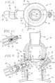
Figure 1 is a perspective view of one side of a valve for controlling flow of pressurized fluid along a path leading from a confined area; -
Fig. 2 is a perspective view of the other side of the valve shown inFig. 1 ; -
Fig. 3 is a plan view of the valve; -
Fig. 4 is a vertical cross-sectional view of the valve taken substantially along the line 4-4 ofFig. 3 and looking in the direction of the arrows; -
Fig. 5 is a vertical cross-sectional view of the valve taken substantially along the line 5-5 ofFig. 3 and looking in the direction of the arrows; -
Fig. 6 is a horizontal cross-sectional view of the valve taken substantially along the line 6-6 ofFig. 4 and looking in the direction of the arrows; -
Fig. 7 a horizontal cross-sectional view of the valve ofFig. 6 with the rupture disc assembly removed; -
Fig. 8 is a vertical cross-sectional view of the valve similar toFig. 4 and diagrammatically illustrating the selectively actuatable device in the disposition thereof that would cause disruption without puncturing the disc, thereby initiating reversal of the central section of the disc; -
Fig. 9 is a vertical cross-section view of the valve as shown inFig. 4 and showing the central section of the bulged reverse buckling rupture disc in its fully open position as a result of disruption of the central section thereof by the shiftable member; -
Fig. 10 is an exploded view of the reverse buckling rupture disc, a backup ring associated with the rupture disc and that has a backup segment positioned to be engaged by the central section of the disc upon reversal and opening thereof, and a clamping ring that engages the backup ring; -
Fig. 11 is a fragmentary cross-sectional view of the selectively actuatable device having a shiftable member movable into engagement with the convex face of the disc, as shown inFig. 4 ; -
Fig. 12 is a fragmentary cross-sectional view of the selectively actuatable device illustrating the shiftable member thereof in its actuated position; -
Fig. 13 is a fragmentary enlarged vertical cross-sectional view of a portion of the structure shown inFig. 4 and better illustrating the disposition of the shiftable member prior to being moved into disrupting engagement with the convex face of the rupture disc; -
Fig. 14 is a fragmentary vertical cross-sectional view through the valve body and illustrating an alternative pivotal selectively actuatable device for disrupting, without puncturing, the disc to effect reversal of the central section of the disc; -
Fig. 15 is a fragmentary vertical cross-sectional view similar toFig. 14 and showing the pivotal device in its disc-disrupting position; -
Fig. 16 is an exploded perspective view of the valve illustrating its component parts; -
Fig. 17 is a vertical cross-sectional view of an alternate embodiment of the present invention comprising a spring actuator shown in the un-deployed position; -
Fig. 18 is a vertical cross-sectional view of the valve ofFig. 17 showing activation of the spring actuator; and -
Fig. 19 is a vertical cross-sectional view of the valve ofFig. 17 showing the spring actuator in the fully deployed position. - The following description sets forth exemplary embodiments according to the present invention. It is to be understood, however, that these embodiments are provided by way of illustration and nothing therein should be taken as a limitation upon the overall scope of the invention.
- Turning now to
Figs. 1 and 2 , thevalve 20 of this invention has any one of a number of uses for releasing pressure from a confined space when that pressure exceeds a predetermined value, and for effecting selective release of pressurized fluid upon command. One form ofvalve 20, as depicted in the drawings, is especially adapted to be connected to the internally-threadedneck 22 of avessel 24, shown as being in a conventional upright position, is adapted to contain a source of pressurized fluid, such as a fire or explosion suppression agent. It is to be understood, however, thatvessel 24 may be oriented other than upright. An O-ring 25 is provided to ensure a fluid-tight seal betweenvalve 20 andvessel 24.Valve 20 includes a two-piece body, broadly designated 26, having a cylindricalupper section 28 and a separate cylindricallower section 30. Lowervalve body section 30 has an externally threadedlowermost portion 32 that is adapted to be threaded intoneck 22 ofvessel 24. The externally-threadedlower portion 34 of uppercylindrical section 28 ofvalve 20 is adapted to be threaded into the internally-threadedupper segment 36 oflower body section 30. Theuppermost segment 38 ofupper body section 28 is adapted to be coupled to a suppressant delivery line through conventional piping or the like, that leads to a respective suppressant delivery nozzle. - The lower
valve body section 30 ofvalve 20 has afluid flow passage 40 therethrough that is axially-aligned with afluid flow passage 42 throughvalve body section 28, that is of essentially the same diameter aspassage 40. Thesuppressant delivery segment 38 ofvalve body 26 has apassage 44 that communicates withpassage 42, but is of a smaller diameter, as shown inFig. 4 . - A reverse buckling
rupture disc 46 is positioned in normal blocking relationship topassages Disc 46 has a circumscribingflange 48 that is trapped between adjacent margins of uppervalve body section 28 and lowervalve body section 30.Disc 46 has a central concavo-convex bulged section 52, in which theconvex surface 54 is in facing relationship to the pressurized fluid invessel 24. In one embodiment of the present invention, the bulgedcentral section 52 ofdisc 46 has a segment 56 (Fig. 3 ) defining a discrete region in which the metal ofsegment 56 has altered grain structure that exhibits greater residual stress than the metal of the remainder of the bulgedsection 52 ofdisc 46. A relatively small diameter region of bulgedsection 52 having the residual stress characteristics ofsegment 56 is described and illustrated in detail in theU.S. Pat. No. 6,945,420 . Preferably,segment 56 is located intermediate the center ofrupture disc 46 and the circumferentially-extending transition area betweenbulged section 52 andflange 48. - An
annular clamping ring 50 and abackup ring 51 are interposed between the lowermost annular edge ofupper body section 28 and theflange 48 ofdisc 46.Backup ring 51 presents an inwardly extendingflange 53 that functions as a support for the bulgedsection 52, and particularly the "hinged" portion thereof (i.e., that portion of bulgedsection 52 which remains attached toflange 48 upon rupture of the disc) and is explained in greater detail below. An O-ring 55 is provided in a circumscribingchannel 57 formed in lowervalve body section 30 to assist in forming a fluid-tight seal betweenrupture disc flange 48 and lowervalve body section 30. Locator pins 49 cooperate withcorresponding grooves rings disc flange 48, respectively, to ensure proper orientation ofrings disc 46 when installed withinvalve body 26. - The
lower body section 30 ofvalve 20 has an integralcylindrical protuberance 58, that is at an angle with respect to the axis ofpassage 40. An outwardly-opening passage 60 inprotuberance 58 communicates with asmaller diameter passage 62 that extends topassage 40 inlower body section 30. Anactuator assembly 64 is received inpassages clip 66.Actuator assembly 64 generally comprises acylindrical actuator body 68, through which is received athruster mechanism 70.Thruster mechanism 70 may be a METRON actuator available from Nobel Enterprises, or other similar type of device. In certain embodiments, the pyrotechnically firedthruster mechanism 70 could be replaced with a solenoid-type thruster mechanism, particularly in applications where activation speed is not critical.Actuator assembly 64 includes an elongated rod orstrike pin 72 that extends throughpassage 62 intopassage 40 inlower body section 30. As shown inFig. 4 ,strike pin 72 presents a bluntoutboard tip 74 that is normally located adjacent, although in spaced relationship with, theconvex surface 54 ofdisc 46 whenpin 72 is in its non-actuated position. -
Thruster mechanism 70 is received inactuator body 68 and secured in place bythreads 76. The throw ofstrike pin 72 is limited byretainer 78 that is threadably received withinprotuberance 58. An O-ring 84 is disposed in a recessed portion ofstrike pin 72 to prevent fluid withinvessel 24 from escaping the valve throughpassage 62. - As shown in
Fig. 11 ,thruster mechanism 70 comprises acylindrical chamber 86 in which is disposed afiring pin 88 and a combustiblepyrotechnic charge 90.Chamber 86 is sealed on one end by a packingplug 92 through which extend a pair oflead wires thruster mechanism 70, the exposed ends oflead wires chamber 86 ignitepyrotechnic charge 90. Ignition ofcharge 90shifts firing pin 88 to the actuated position as shown inFig. 12 . In certain embodiments, the throw or linear displacement of firing pin 88 (and consequently of strike pin 72) is between about 6 to about 12 mm, and preferably about 9 mm. As explained below, upon actuation, firingpin 88 contacts and/or acts uponend 100 ofstrike pin 72 thereby causingstrike pin 72 to shift to the actuated position and strikerupture disc 46. - Lower
valve body section 30 also presents aside port 102 extending outwardly and obliquely therefrom.Side port 102 presents a frustoconically shapedpassage 104 in which ashrader valve 106 is disposed.Passage 104 is in communication with abore 108 presenting a larger diameter. As shown inFig. 4 , aplug 110 is threadably received withinbore 108. However, bore 106 may also be outfitted with a pressure gauge so that the pressure of fluid withinpassage 40 andvessel 24 may be monitored. - Lower
valve body section 30 also presents a laterally extendingfill port 112 that may be used to chargevessel 24 with the desired fluid after installation ofvalve 20 thereon. As shown inFig. 5 , fillport 112 comprises a generallycylindrical bore 114 in which afill port insert 116 and fillport plug 118 are normally disposed and threadably secured therein. Fillport insert 116 is essentially a check valve that presents afirst passage 120 that communicates with asecond passage 122, thefirst passage 120 presenting a diameter that is less than the diameter of thesecond passage 122. Aball 124 having a diameter that is greater than the diameter of thefirst passage 120 is disposed withinfill port insert 116 and operates to block communication betweenfirst passage 120 andsecond passage 122 when the fluid pressure withinpassage 40 andvessel 24 is greater than the fluid pressure withinfirst passage 120. Thus, fillport insert 116 generally permits only unidirectional flow of fluid from the fill port bore 114 into the lower valvebody section passage 40. A frittedcheck disc 126 is provided at the end ofbore 114opposite plug 118 to preventball 124 from escapingsecond passage 122 during filling ofvessel 24. - An
auxiliary port 128 extends outwardly from lowervalve body section 30 and presents a generallycylindrical bore 130 therethrough. As shown inFig. 5 , aplug 132 is normally threadably received withinbore 130. However, auxiliary apparatus, such as an auxiliary pressure gauge, may be coupled toport 128 in place ofplug 132. Apassageway 134 communicates fill port bore 114 with lowervalve body passage 40 andauxiliary bore 130. -
Valve 20 may be used to release pressurized fluid from a confined space through active initiation of the reversal and rupture ofrupture disc 46.Valve 20 also provides passive protection against dangerous overpressure conditions withinvessel 24 through reversal and rupture ofdisc 46 should such an overpressure condition come to exist. Thus, reverse bucklingrupture disc 46 is capable of withstanding the lower, normal fluid pressures withinvessel 24, but also capable of being selectively opened when release of the pressurized fluid is desired. In certain embodiments of the present invention,valve 20 is mounted in the flow path of fire or explosion suppression apparatus to allow flow of a suppressant agent therethrough in response to a pressure relief command. In certain embodiments, the pressure relief command is automatically generated by a detector or sensor located within a space in which the suppression apparatus is installed, however, such command may also be manually given. - In its normal, un-actuated configuration, as shown in
Fig. 13 ,strike pin 72 is shown proximate to, but spaced apart from, theconvex surface 54 ofdisc 46. As previously noted, in certain embodiments,disc 46 may be provided with pre-stressed,discrete segment 56 having an altered grain structure than the rest of disc bulgedsection 52. In one embodiment,strike pin tip 74 is disposed proximate to, but not touching,segment 56. When actuated,tip 74 engagessegment 56 to initiate reversal ofdisc 46. However, in the un-actuated configuration ofvalve 20,disc 46 effectively contains the pressurized fluid present inpassage 40 andvessel 24 by blocking the flow path topassage 42. - Upon detection of a condition (other than an overpressure condition within vessel 24) requiring the release of the pressurized fluid, an electrical signal is transmitted to
actuator assembly 64, and specifically, tothruster mechanism 70 vialead wires pyrotechnic charge 90 contained withinchamber 86 thereby advancingfiring pin 88 toward an extended position as illustrated inFig. 12 . In certain embodiments, the speed at which the firing pin advances is less than the speed of sound, preferably less than 1100 ft/sec. By limiting the speed in this fashion, piercing of therupture disc 46 and fragmentation ofdisc 46 upon opening are more reliably avoided.Firing pin 88 contacts thestrike pin end 100 thereby causing strike pin to advance along a rectilinear path toward the rupture discconvex surface 54 and come into contact therewith.Strike pin tip 74 is of a rounded shape, as opposed to coming to a sharp point. Thus, whenstrike pin 72 is shifted through a predetermined displacement, contact withconvex surface 54 is sufficient to effect disruption thereof without puncturingdisc 46. As shown inFig. 8 ,strike pin 72 mechanically disrupts and causes a deformation of the disc bulgedsection 52, but does not penetratedisc 46. Penetration ofdisc 46 is undesirable as thepin 74 could simply plug the opening created thereby blocking the flow of fluid intopassage 42 and causing the disc to fail to open. -
Strike pin 72 imparts sufficient kinetic energy to the disc bulgedsection 52 such that when combined with the force of the fluid acting upon the discconvex surface 54,disc 46 reverses and opens. More particularly, the force exerted on bulgedsection 52 by the impact ofstrike pin 72 coupled with the force exerted by the pressurized fluid is sufficient to initiate reversal and opening ofdisc 46. In certain embodiments, thecentral bulged section 52 reverses at a faster rate than the movement ofstrike pin 72 towarddisc 46 upon initiation of reversal ofsection 52. Thus, full opening ofdisc 46 is achieved at fluid pressure conditions as low as 20% (one-fifth) of the rated burst pressure of the disc (i.e., the pressure at which the disc will automatically reverse and rupture without the assistance ofactuator assembly 64 to a tolerance of ±5%). However, in certain embodiments, full opening of the disc is achieved when the fluid pressure is no more than about one-half of the rated burst pressure. In still other embodiments, full opening of the disc is achieved at between about 25-75% of the rated burst pressure of the disc, and more particularly about 33% of the rated burst pressure of the disc. In certain embodiments of the present invention, full opening ofdisc 46 may be achieved in as little as 5-10 msec. - In the embodiment shown in
Figs. 1-13 ,protuberance 58 andactuator assembly 64 are positioned at an oblique angle relative to the fluid flow path throughpassages protuberance 58 andactuator assembly 64 to be perpendicular or parallel to this flow path. Further,actuator assembly 64 may be configured so thatstrike pin 72contacts rupture disc 46 at any portion of the disc'sconvex surface 54. In one embodiment,strike pin 72 is movable toward central bulgedsection 52 in generally tangential relationship toconvex surface 54. In another embodiment,strike pin 72 is movable toward central bulgedsection 52 in generally perpendicular relationship toconvex surface 54. Regardless of the relative direction of travel, it is preferable to strike the disc at or near its weakest point. In the case ofdisc 46,strike pin 72 is shown contacting the disc proximate thepre-stressed segment 56 formed in bulgedsection 52. In the case of other discs not presenting a correspondingsegment 56,strike pin 72 may contact the disc at a location toward the peak of the bulged section where the disc material is the thinnest. By striking the disc at or near its weakest point, less kinetic energy is required thereby reducing the likelihood that strikepin 72 will pierce the disc. In whatever actuator assembly configuration selected, to achieve successful selective opening ofdisc 46, the force vector supplied bypin 72 acting on the disc in the same direction as the force vector supplied by the pressurized fluid will need to be sufficient to initiate reversal and opening ofdisc 46. - Reverse buckling
rupture disc 46 may be provided with a semicircular score line or line of weakness that is located proximate thetransition zone 138 betweenflange 48 and bulged section 52 (seeFig. 10 ). Upon actuation ofactuator assembly 64 and contact betweenstrike pin 72 and discconvex surface 54, the disc bulgedsection 56 opens proximate the line of weakness leaving only asmall hinge portion 140 attached toflange 46. Upon opening of the disc,hinge portion 140 is supported byflange 53 ofbackup ring 51. Fluid escaping fromvessel 24 through the flow path presented bypassages disc 46 to fold around flange 53 as shown inFig. 9 . In this manner,flange 53 assists in preventing undesired fragmentation ofdisc 46. It will be appreciated that other types of non-fragmenting reverse buckling rupture discs may be employed with different score line configurations, such as discs that form a plurality of petals upon opening. - An alternate embodiment of the present invention is depicted in
Figs. 14 and 15 . Generally, thevalve 20 is configured as described above. However,actuator assembly 64 has been replaced with a swingingarm actuator 142.Actuator 142 includes a laterally extendingtoe segment 144 configured to contact, but not puncture,convex surface 54 ofrupture disc 46. Shifting ofactuator 142 along a curvilinear path may be effected by use of a latch and spring mechanism (not shown) or by other means known to those of skill in the art to causeactuator 142 to shift andtoe segment 144 to impactconvex surface 54. - Yet another embodiment of the present invention is depicted in
Figs. 17-19 . This embodiment is very similar to the embodiment shown inFigs. 1-9 and16 , except that aspring actuator mechanism 146 is positioned betweenactuator assembly 64 andprotuberance 58. One function of thespring actuator 146 is to translate the force generated bythruster mechanism 70 into a much larger force that would act uponstrike pin 72. Thus,spring actuator 146 is particularly suited for those applications in whichthruster mechanism 70 is not by itself sufficient to causestrike pin 72 to contact rupture disc bulgedportion 54 with the required level of force. By usingspring actuator 146, a relatively large motive force output can be generated by the action of a relatively small motive force input. -
Spring actuator 146 generally comprises aforce input housing 148 threadably secured to aforce output housing 150.Input housing 148 is coupled toactuator body 68 and secured by a retainingclip 152.Output housing 150 is secured toprotuberance 58 by retainingclip 66. Anactuation piston 154 is contained withininput housing 148 and adjacent a profiledpiston 156. Profiledpiston 156 extends betweeninput housing 148 andoutput housing 150 into anannular region 158 ofplunger 160. Profiledpiston 156 contains a plurality of recessedportions 162 configured to receiveballs 164. The head of profiledpiston 156 contains a hollowed-outportion 166 in which aspring 168 is received.Spring 168 also engagesplunger 160 so as to bias profiledpiston 156 andplunger 160 apart. The head ofpiston 156 is maintained withinannular region 158 by a retainingring 170. Awasher 172 overliesring 170 and effectively closes offannular region 158. Asecond washer 174 is provided so as to cooperate withwasher 172 in providing surfaces against whichmain spring 176 coiled about profiledpiston 156 exerts aforce biasing plunger 160 towardstrike pin 72. When in the un-activated position,balls 164 reside inorifices 178 formed inannular region 158 ofplunder 160.Balls 164 rest up againstseats 180 thus prohibiting shifting ofplunger 160 in response to the force exerted thereupon bymain spring 176. - As shown in
Fig. 18 , Upon activation ofthruster mechanism 70, firingpin 88contacts actuation piston 154 thereby shiftingactuation piston 154 towardvalve body 26. The shifting ofactuation piston 154 causes profiledpiston 156 also to shift in the same direction. The shifting of profiledpiston 156 compressesspring 168 and causesorifices 178 to align with recessedportions 162. As a result of this alignment,seats 180force balls 164 into recessedportions 162 and out of engagement with the seats. When in this configuration,balls 164 effectively lock profiledpiston 156 andplunger 160 together to prohibit relative movement therebetween. Further, withballs 164 out of engagement withseats 180,main spring 176, which to this point has been under compression, acts upon the combined profiledpiston 156 andplunger 160 assembly causing it to shift towardvalve body 26 and into contact withstrike pin 72. -
Fig. 19 illustratesspring actuator 146 in its fully deployed position. As can be seen,actuation piston 154 and profiledpiston 156 are no longer in contact with each other.Strike pin 72 has contacted bulgedsection 52 ofrupture disc 46 thus initiating reversal and opening of the disc. -
Spring actuator 146 may be actuated by means other than athruster mechanism 70 which employs a pyrotechnic charge.Spring actuator 146 is provided with a plurality offluid ports 182 that may be connected to a source of pressurized fluid, such as compressed air or nitrogen. Upon detection of conditions requiring activation ofvalve 20, the pressurized fluid may be delivered toports 182. Theports 182 communicate with the interior ofinput housing 148 viapassages 184. The pressurized fluid acts upon the head ofactuation piston 154 causing the piston to shift towardvalve body 26. O-rings actuation piston 154 prevent the pressurized fluid from escaping into other portions ofspring actuator 146. - One of skill in the art would appreciate other means of actuating
spring actuator 146, such as through the use of a solenoid. Therefore, the present invention is not merely limited to the above-described embodiments. - After activation,
spring actuator 146 may be disconnected fromprotuberance 58 and reset for reuse. During resetting,plunger 160 is shifted back intooutput housing 150 thereby compressingmain spring 176. Onceplunger 160 and profiledpiston 156 are sufficiently shifted towardsinput housing 148 andballs 164 have passedseats 180,balls 164 become displaced from recessedportions 162 thereby separatingplunger 160 and profiledpiston 156.Spring 168 shifts profiledpiston 156 into contact withactuation piston 154, and bothpistons Fig. 17 .
Claims (11)
- A valve (20) for controlling flow of pressurized fluid along a path leading from a confined area comprising:a tubular valve body (26) provided with a fluid passage (40, 42) and adapted to be mounted in said fluid path;a reverse buckling rupture disc (46) carried by the valve body (26) in normal blocking relationship to flow of fluid through said passage (40, 42), said disc (46) having a bulged central section (52) presenting a generally convex surface (54) and a concave face, said central section (52) of the disc (46) being operable to resist reversal and rupture thereof under a predetermined first fluid pressure there against, said disc being disposed with the convex surface (54) thereof in facing relationship to the pressurized fluid; anda selectively operable device (64) carried by the body (26) in disposition adjacent the convex surface (54) of the central section (52) of the disc (46) that is operable upon actuation to mechanically disrupt, without puncturing, the central section (52) of the disc (46) to an extent that reversal of the central section (52) of the disc (46) is initiated at a predetermined second fluid pressure that is less than said first predetermined pressure to allow flow of fluid through the valve passage.
- A valve (20) as set forth in claim 1, wherein said device (64) includes a shiftable member (72) normally spaced from the convex surface (54) of the central section (52) of the disc (46) and movable through a displacement to engage the convex surface (54) and effect disruption thereof without puncture of the central section (52).
- A valve (20) as set forth in claim 2, wherein said member (72) is movable toward the central section (52) of the disc (46) in generally tangential relationship to the convex surface (54) thereof, or in generally perpendicular relationship to the convex surface (54) thereof.
- A valve (20) as set forth in claim 2, wherein said member is a rod (72) having a blunt end (74) engageable with the convex surface (54) of the bulged central section (52) of the disc (46).
- A valve (20) as set forth in claim 2, wherein is provided a pyrotechnic charge (90) operable to effect shifting of the member (72) through said displacement thereof upon ignition of the charge (90).
- A valve (20) as set forth in claim 2, wherein said member (72) is movable through a predetermined displacement sufficient only to effect disruption of the convex surface (54) of the central section (52) of the disc (46) without puncturing the central section (52), and/or wherein said member (72) is movable along a generally curvilinear path of travel.
- A valve (20) as set forth in claim 2, wherein the central section (52) of the disc (46) reverses at a faster rate than movement of the member (72) toward the disc (46) upon initiation of reversal of the central section (52) of the disc (46).
- A valve (20) as set forth in claim 2, wherein said member (72) is movable along a generally rectilinear path of travel or along a generally curvilinear path of travel.
- A valve (20) as set forth in claim 1, wherein the rupture disc (46) is of one piece metal and said bulged central section (52) of the disc (46) has a segment (56) defining a discrete region in which the metal of the segment (56) has altered grain structure that exhibits greater residual stress than the metal of the remainder of the central section (52) of the disc (46), reversal of the central section (52) of the disc (46) being initiated at said discrete region thereof.
- A valve (20) as set forth in claim 8, wherein the convex surface (54) and the concave face of the central section (52) of the disc (46) are smooth and of uninterrupted configuration throughout the entire area thereof including the segment (56) defining said discrete region of the bulged central section (52).
- A valve (20) as set forth in claim 8, wherein said device (64) is positioned to engage said discrete region (56) of the disc (46) to effect initiation of disruption of the central section (52) of the disc (46) at said discrete region (56).
Priority Applications (2)
| Application Number | Priority Date | Filing Date | Title |
|---|---|---|---|
| PL18204748T PL3460300T3 (en) | 2008-11-21 | 2009-09-03 | Impulse actuated valve |
| SI200932136T SI3460300T1 (en) | 2008-11-21 | 2009-09-03 | Impulse actuated valve |
Applications Claiming Priority (3)
| Application Number | Priority Date | Filing Date | Title |
|---|---|---|---|
| US12/275,724 US7878215B2 (en) | 2008-11-21 | 2008-11-21 | Impulse actuated valve |
| EP09827920.1A EP2347151B1 (en) | 2008-11-21 | 2009-09-03 | Impulse actuated valve |
| PCT/US2009/055816 WO2010059282A2 (en) | 2008-11-21 | 2009-09-03 | Impulse actuated valve |
Related Parent Applications (1)
| Application Number | Title | Priority Date | Filing Date |
|---|---|---|---|
| EP09827920.1A Division EP2347151B1 (en) | 2008-11-21 | 2009-09-03 | Impulse actuated valve |
Publications (2)
| Publication Number | Publication Date |
|---|---|
| EP3460300A1 EP3460300A1 (en) | 2019-03-27 |
| EP3460300B1 true EP3460300B1 (en) | 2021-05-26 |
Family
ID=42195379
Family Applications (2)
| Application Number | Title | Priority Date | Filing Date |
|---|---|---|---|
| EP18204748.0A Active EP3460300B1 (en) | 2008-11-21 | 2009-09-03 | Impulse actuated valve |
| EP09827920.1A Active EP2347151B1 (en) | 2008-11-21 | 2009-09-03 | Impulse actuated valve |
Family Applications After (1)
| Application Number | Title | Priority Date | Filing Date |
|---|---|---|---|
| EP09827920.1A Active EP2347151B1 (en) | 2008-11-21 | 2009-09-03 | Impulse actuated valve |
Country Status (19)
| Country | Link |
|---|---|
| US (1) | US7878215B2 (en) |
| EP (2) | EP3460300B1 (en) |
| JP (1) | JP5474083B2 (en) |
| KR (1) | KR101595143B1 (en) |
| CN (1) | CN102224365B (en) |
| AU (1) | AU2009318049B2 (en) |
| BR (1) | BRPI0922054B1 (en) |
| CA (1) | CA2742618C (en) |
| EG (1) | EG26798A (en) |
| HK (1) | HK1159730A1 (en) |
| MX (1) | MX2011004806A (en) |
| PL (2) | PL2347151T3 (en) |
| RU (1) | RU2493464C2 (en) |
| SA (1) | SA109300585B1 (en) |
| SG (1) | SG171778A1 (en) |
| SI (2) | SI3460300T1 (en) |
| TR (1) | TR201900717T4 (en) |
| TW (1) | TWI479117B (en) |
| WO (1) | WO2010059282A2 (en) |
Families Citing this family (21)
| Publication number | Priority date | Publication date | Assignee | Title |
|---|---|---|---|---|
| US8757191B2 (en) | 2011-12-08 | 2014-06-24 | Kiddie Technologies, Inc. | High rate discharge (HRD) valve opening mechanism for a fire and explosion protection |
| US8776820B2 (en) | 2011-12-08 | 2014-07-15 | Kidde Technologies, Inc. | High rate discharge (HRD) valve incorporating a collet sleeve release mechanism |
| US8800585B2 (en) | 2011-12-08 | 2014-08-12 | Kidde Technologies, Inc. | High rate discharge (HRD) valve incorporating a rotating lever release mechanism |
| DE102012011988A1 (en) * | 2012-06-16 | 2013-12-19 | Atlas Elektronik Gmbh | Closure device for a pressure accumulator, torpedo with a pressure accumulator and such a closure device for the pressure accumulator and use of such a closure device for the closure of a pressure accumulator of a torpedo |
| EP2747087A1 (en) * | 2012-12-22 | 2014-06-25 | AREVA GmbH | Pipe shut-off device and apparatus for the emergency supply of cooling fluid to the fuel rods arranged in the reactor vessel of an nuclear power station with such a pipe shut-off device |
| US9861846B2 (en) * | 2015-01-22 | 2018-01-09 | Kidde Technologies, Inc. | Spring-collet mechanism for activating a fire extinguisher |
| EP3112732A1 (en) * | 2015-07-02 | 2017-01-04 | Rembe GmbH Safety + Control | Bursting disc assembly with a bursting disc and an actuator |
| US10677365B2 (en) * | 2015-09-04 | 2020-06-09 | S.P.M. Flow Control, Inc. | Pressure relief valve assembly and methods |
| CA3003887A1 (en) | 2015-11-06 | 2017-05-11 | Oklahoma Safety Equipment Company, Inc. | Rupture disc device and method of assembly thereof |
| DE102015014797A1 (en) * | 2015-11-14 | 2017-05-18 | Hydac Technology Gmbh | safety device |
| CA3035300A1 (en) * | 2016-08-29 | 2018-03-08 | John Tomasko | Pressure relief module |
| ES2808959T3 (en) * | 2017-01-25 | 2021-03-02 | Rembe Gmbh Safety Control | Rupture disc arrangement with a rupture disc and actuator for reduction of the rupture pressure |
| US10527183B1 (en) * | 2017-05-01 | 2020-01-07 | KHOLLE Magnolia 2015, LLC | Pressure relief valve |
| US10481620B2 (en) | 2017-05-26 | 2019-11-19 | Goodrich Corporation | Pneumatic inflation system |
| US10794506B2 (en) * | 2018-07-31 | 2020-10-06 | Rembe Gmbh Safety + Control | Rupture disc assembly with a rupture disc and an actuator for reducing the rupture pressure |
| EP3835635A1 (en) | 2019-12-13 | 2021-06-16 | Goodrich Corporation | Pneumatic valve with rupturable membrane |
| IT202000023368A1 (en) | 2020-10-05 | 2022-04-05 | Bind Fire S R L | RELEASE VALVE FOR FIRE-FIGHTING SYSTEMS, FIRE-FIGHTING SYSTEM AND RELATED METHOD OF ACTIVATION |
| EP4237716A1 (en) * | 2020-10-28 | 2023-09-06 | Aerojet Rocketdyne, Inc. | Fuel-isolation system having rupture diaphragm |
| IT202000026257A1 (en) | 2020-11-04 | 2022-05-04 | Bind Fire S R L | HEAT ACTIVATED RELEASE VALVE FOR FIRE-FIGHTING SYSTEMS, FIRE-FIGHTING SYSTEM AND ITS OPERATING METHOD |
| WO2022195519A1 (en) * | 2021-03-17 | 2022-09-22 | Bs&B Innovations Limited | Kinetic hinge for a pressure relief device |
| US11933413B2 (en) * | 2022-07-26 | 2024-03-19 | Oseco Inc. | Support structure for a reverse buckling rupture disc |
Family Cites Families (70)
| Publication number | Priority date | Publication date | Assignee | Title |
|---|---|---|---|---|
| US1671368A (en) | 1926-01-18 | 1928-05-29 | Co Fire Equipment Co | Electromagnetic control for fluid containers |
| US2206818A (en) | 1938-10-26 | 1940-07-02 | Specialties Dev Corp | Self-energizing fluid release device |
| US2417082A (en) | 1944-03-13 | 1947-03-11 | Specialties Dev Corp | Apparatus for discharging fluids under pressure |
| US2441011A (en) | 1946-10-10 | 1948-05-04 | Pyrene Mfg Co | Discharge head for pressure fluid tanks |
| US2766832A (en) | 1953-01-26 | 1956-10-16 | Graviner Manufacturing Co | Appliance for extinguishing fires and suppressing explosions |
| US3027903A (en) | 1958-10-31 | 1962-04-03 | Universal Match Corp | Explosively actuated valves |
| US3101733A (en) | 1961-07-14 | 1963-08-27 | United Aircraft Prod | Explosive valve |
| US3134390A (en) | 1962-01-02 | 1964-05-26 | Futurecraft Corp | Shearable disc butterfly valve |
| US3129716A (en) | 1962-02-05 | 1964-04-21 | Thiokol Chemical Corp | Explosive actuated valve |
| US4421005A (en) | 1962-03-28 | 1983-12-20 | The United States Of America As Represented By The United States Department Of Energy | Explosive actuated valve |
| US3196610A (en) * | 1963-05-03 | 1965-07-27 | Thiokol Chemical Corp | Solid propellant rocket motor having reverse thrust generating means |
| JPS4414588Y1 (en) * | 1966-07-30 | 1969-06-21 | ||
| JPS4522170Y1 (en) * | 1967-06-03 | 1970-09-03 | ||
| US3604511A (en) | 1969-01-16 | 1971-09-14 | Commercial Solvents Corp | Method and apparatus for quenching fires and suppressing explosions |
| DE2118745C3 (en) | 1971-04-17 | 1980-07-17 | Dynamit Nobel Ag | Gas delivery unit for an inflatable occupant impact protection system in vehicles |
| BE786098A (en) | 1971-07-12 | 1972-11-03 | Graviner Colnbrook Ltd | FIRE EXTINGUISHING SYSTEMS |
| JPS4876508U (en) | 1971-12-23 | 1973-09-21 | ||
| US3913604A (en) | 1972-07-13 | 1975-10-21 | David E Hanson | Piston-actuated fluid discharge device |
| US4018457A (en) | 1972-09-05 | 1977-04-19 | Olin Corporation | Inflating device for use with vehicle safety systems |
| SU476398A1 (en) * | 1973-03-15 | 1975-07-05 | Предприятие П/Я В-2289 | Pyro valve |
| US3931604A (en) | 1974-04-10 | 1976-01-06 | Treynor Paul E | Sampling automatic equalizer |
| US3938704A (en) | 1974-05-23 | 1976-02-17 | Offshore Devices, Inc. | Inflation control valves |
| US4046156A (en) | 1975-12-04 | 1977-09-06 | Systron-Donner Corporation | Explosion discharge valve |
| US4006780A (en) | 1976-05-24 | 1977-02-08 | The Protectoseal Company | Rupturing head for fire extinguishers |
| CA1087066A (en) * | 1977-08-15 | 1980-10-07 | Bs & B Safety Systems, Inc. | Fluid pressure relief apparatus |
| IL54139A0 (en) | 1978-02-27 | 1978-04-30 | Spector D | Fire and explosion suppression apparatus |
| SU870830A1 (en) * | 1979-06-11 | 1981-10-07 | Предприятие П/Я Г-4665 | Safety mebrane valve |
| US4245660A (en) * | 1979-11-05 | 1981-01-20 | The United States Of America As Represented By The Secretary Of The Army | Manual override for short stroke valve |
| US4436159A (en) | 1981-05-01 | 1984-03-13 | Kidde, Inc. | Manual/electric activated squib actuated discharge valve for fire extinguishers |
| IE53568B1 (en) * | 1982-01-02 | 1988-12-07 | Imi Marston Ltd | A bursting disc utilising flexible graphite |
| FR2544445B1 (en) | 1983-04-14 | 1985-06-21 | Electricite De France | SAFETY DEVICE WITH MEMBRANE AND BREAKING KNIFE FOR LIMITING THE PRESSURE OF A FLUID |
| US4542761A (en) | 1983-07-11 | 1985-09-24 | Hr Textron Inc. | Fluid delivery system |
| US4779683A (en) | 1983-09-21 | 1988-10-25 | Enk William A | Discharge control head for aircraft fire extinguishant containers |
| US4630682A (en) | 1985-02-21 | 1986-12-23 | Central Sprinkler Corporation | Rapid response sprinkler head |
| US4566476A (en) | 1985-03-29 | 1986-01-28 | Draft Systems, Inc. | Flow control device |
| FR2608720B1 (en) | 1986-12-18 | 1989-03-03 | Electricite De France | MEMBRANE SAFETY DEVICE WITH ACTIVE UPSTREAM BLADE KNIFE |
| US4838447A (en) * | 1987-06-29 | 1989-06-13 | Bs&B Safety Systems, Inc. | Pressure relief device with conical reverse buckling disc |
| EP0308544B1 (en) | 1987-09-21 | 1993-10-06 | Akzo Nobel N.V. | Explosion-safe liquid container |
| US5010911A (en) | 1989-12-15 | 1991-04-30 | Wormald U.S., Inc. | Electromagnetic valve operator |
| US5076312A (en) | 1990-01-25 | 1991-12-31 | Tip Engineering Group, Inc. | Pressure relief device |
| US5022674A (en) | 1990-04-05 | 1991-06-11 | Bendix Atlantic Inflator Company | Dual pyrotechnic hybrid inflator |
| US5257819A (en) | 1990-11-27 | 1993-11-02 | Bendix Atlantic Inflator Company | Hybrid inflator |
| JP2519205Y2 (en) * | 1991-09-04 | 1996-12-04 | 日本発条株式会社 | Suspension device for vehicle seat |
| US5345876A (en) | 1993-02-04 | 1994-09-13 | Atlantic Research Corporation | Hybrid inflator |
| US5934308A (en) * | 1995-10-24 | 1999-08-10 | Bs&B Safety Systems, Inc. | Rupture disk apparatus and methods |
| DE19638838A1 (en) | 1996-09-21 | 1998-03-26 | Dynamit Nobel Ag | Hybrid gas generator for an airbag with a mechanical opening mechanism for the storage chamber |
| US6694975B2 (en) * | 1996-11-21 | 2004-02-24 | Aradigm Corporation | Temperature controlling device for aerosol drug delivery |
| US6006938A (en) | 1997-09-18 | 1999-12-28 | Continental Disc Corporation | Enhanced reverse buckling rupture disc |
| US6240948B1 (en) | 1999-01-05 | 2001-06-05 | Hansen Technologies Corporation | Rupture disk assembly |
| US6178983B1 (en) * | 1999-05-13 | 2001-01-30 | Bs&B Safety Systems, Inc. | Rupture disk assembly |
| IT248945Y1 (en) * | 1999-07-06 | 2003-03-06 | Eusebi Impianti S R L | VALVE FOR HIGH PRESSURE GAS CYLINDERS |
| AU4712801A (en) | 1999-12-09 | 2001-06-18 | Autoliv Asp | Vehicle inflator for generating shock wave that opens burst disc |
| JP2002211346A (en) | 2001-01-15 | 2002-07-31 | Takata Corp | Inflator |
| GB2373310B (en) | 2001-03-15 | 2005-02-02 | Autoliv Dev | Improvements in or relating to an inflator |
| JP2002347567A (en) | 2001-05-29 | 2002-12-04 | Takata Corp | Inflator |
| US6629703B2 (en) | 2001-12-14 | 2003-10-07 | Breed Automotive Technology, Inc. | Opening device for a cold gas inflator |
| FI113155B (en) | 2002-01-17 | 2004-03-15 | Marioff Corp Oy | valve element |
| FI115291B (en) | 2002-01-17 | 2005-04-15 | Marioff Corp Oy | The valve member |
| FI118987B (en) | 2002-04-19 | 2008-06-13 | Marioff Corp Oy | The valve member |
| ATE349239T1 (en) * | 2002-04-26 | 2007-01-15 | Gl Tool And Mfg Co Inc | VALVE |
| US7350535B2 (en) | 2002-04-26 | 2008-04-01 | Gl Tool And Manufacturing Co. Inc. | Valve |
| US6748743B1 (en) | 2002-07-03 | 2004-06-15 | Richard W. Foster-Pegg | Indirectly heated gas turbine control system |
| US6748783B1 (en) | 2002-10-30 | 2004-06-15 | J-Dan | Bend/cut-off gauge for a portable sheet bending brake |
| JP2004274910A (en) * | 2003-03-10 | 2004-09-30 | Yaskawa Electric Corp | Bursting device for gas switch |
| US6945420B2 (en) | 2003-03-28 | 2005-09-20 | Fike Corporation | Reverse buckling sanitary rupture disc assembly |
| US7093451B2 (en) | 2003-09-18 | 2006-08-22 | Delphi Technologies, Inc. | Blowoff valve assembly with integrated pressure switch |
| US7281672B2 (en) | 2004-03-11 | 2007-10-16 | Kidde-Fenwal, Inc. | Dual burst disk |
| US7373944B2 (en) | 2004-12-27 | 2008-05-20 | Autoliv Asp, Inc. | Pyrotechnic relief valve |
| US8038024B2 (en) | 2005-01-14 | 2011-10-18 | Fike Corporation | Holder with V-knife blade for bi-directional rupture disc assembly |
| DE102007022018B4 (en) | 2006-05-13 | 2023-04-20 | Rembe Gmbh Safety + Control | Rupture disc and method of making the same |
-
2008
- 2008-11-21 US US12/275,724 patent/US7878215B2/en active Active
-
2009
- 2009-09-01 TW TW098129370A patent/TWI479117B/en active
- 2009-09-03 EP EP18204748.0A patent/EP3460300B1/en active Active
- 2009-09-03 CN CN2009801470410A patent/CN102224365B/en active Active
- 2009-09-03 WO PCT/US2009/055816 patent/WO2010059282A2/en active Application Filing
- 2009-09-03 SI SI200932136T patent/SI3460300T1/en unknown
- 2009-09-03 RU RU2011139706/06A patent/RU2493464C2/en active
- 2009-09-03 SI SI200931924T patent/SI2347151T1/en unknown
- 2009-09-03 TR TR2019/00717T patent/TR201900717T4/en unknown
- 2009-09-03 PL PL09827920T patent/PL2347151T3/en unknown
- 2009-09-03 EP EP09827920.1A patent/EP2347151B1/en active Active
- 2009-09-03 JP JP2011537446A patent/JP5474083B2/en active Active
- 2009-09-03 MX MX2011004806A patent/MX2011004806A/en active IP Right Grant
- 2009-09-03 BR BRPI0922054A patent/BRPI0922054B1/en active IP Right Grant
- 2009-09-03 SG SG2011036662A patent/SG171778A1/en unknown
- 2009-09-03 AU AU2009318049A patent/AU2009318049B2/en active Active
- 2009-09-03 PL PL18204748T patent/PL3460300T3/en unknown
- 2009-09-03 KR KR1020117009960A patent/KR101595143B1/en active IP Right Grant
- 2009-09-03 CA CA2742618A patent/CA2742618C/en active Active
- 2009-09-28 SA SA109300585A patent/SA109300585B1/en unknown
-
2011
- 2011-05-15 EG EG2011050757A patent/EG26798A/en active
-
2012
- 2012-01-10 HK HK12100278A patent/HK1159730A1/en unknown
Non-Patent Citations (1)
| Title |
|---|
| None * |
Also Published As
Similar Documents
| Publication | Publication Date | Title |
|---|---|---|
| EP3460300B1 (en) | Impulse actuated valve | |
| JP2012509449A5 (en) | ||
| US5230531A (en) | Gas generator ignition assembly using a projectile | |
| US4046156A (en) | Explosion discharge valve | |
| EP1800972B1 (en) | Inflator having an improved closure cap | |
| RU2493892C2 (en) | High-integrity fluid discharge device | |
| AU2010226971B2 (en) | Fire suppression system | |
| EP3023123B1 (en) | Poppet valve with a frangible sealing disc for a pressure vessel | |
| EP0862003B1 (en) | Release mechanism for a pressure vessel | |
| US6076610A (en) | Vehicular fire extinguishing device | |
| US6006842A (en) | Non-fragmenting, non-explosive actuating valve mechanism for fire suppression apparatus | |
| KR102578258B1 (en) | Valve apparatus for automatic fire extinguisher | |
| CN216703237U (en) | Starting device and fire extinguishing apparatus | |
| CN113577621A (en) | Starting device and fire extinguishing apparatus | |
| US4476937A (en) | Rapid acting two stage pyrotechnic valve for fixed fire extinguishers | |
| CN113577623A (en) | Starting device and fire extinguishing apparatus | |
| US20230356016A1 (en) | Release valve for fire protection systems, fire protection system and relative activation method | |
| RU2270710C1 (en) | Shutoff and triggering device for gas fire extinguishing plant |
Legal Events
| Date | Code | Title | Description |
|---|---|---|---|
| PUAI | Public reference made under article 153(3) epc to a published international application that has entered the european phase |
Free format text: ORIGINAL CODE: 0009012 |
|
| STAA | Information on the status of an ep patent application or granted ep patent |
Free format text: STATUS: REQUEST FOR EXAMINATION WAS MADE |
|
| 17P | Request for examination filed |
Effective date: 20181106 |
|
| AC | Divisional application: reference to earlier application |
Ref document number: 2347151 Country of ref document: EP Kind code of ref document: P |
|
| AK | Designated contracting states |
Kind code of ref document: A1 Designated state(s): AT BE BG CH CY CZ DE DK EE ES FI FR GB GR HR HU IE IS IT LI LT LU LV MC MK MT NL NO PL PT RO SE SI SK SM TR |
|
| GRAP | Despatch of communication of intention to grant a patent |
Free format text: ORIGINAL CODE: EPIDOSNIGR1 |
|
| STAA | Information on the status of an ep patent application or granted ep patent |
Free format text: STATUS: GRANT OF PATENT IS INTENDED |
|
| INTG | Intention to grant announced |
Effective date: 20201204 |
|
| GRAS | Grant fee paid |
Free format text: ORIGINAL CODE: EPIDOSNIGR3 |
|
| GRAA | (expected) grant |
Free format text: ORIGINAL CODE: 0009210 |
|
| STAA | Information on the status of an ep patent application or granted ep patent |
Free format text: STATUS: THE PATENT HAS BEEN GRANTED |
|
| AC | Divisional application: reference to earlier application |
Ref document number: 2347151 Country of ref document: EP Kind code of ref document: P |
|
| AK | Designated contracting states |
Kind code of ref document: B1 Designated state(s): AT BE BG CH CY CZ DE DK EE ES FI FR GB GR HR HU IE IS IT LI LT LU LV MC MK MT NL NO PL PT RO SE SI SK SM TR |
|
| REG | Reference to a national code |
Ref country code: GB Ref legal event code: FG4D |
|
| REG | Reference to a national code |
Ref country code: CH Ref legal event code: EP |
|
| REG | Reference to a national code |
Ref country code: AT Ref legal event code: REF Ref document number: 1396558 Country of ref document: AT Kind code of ref document: T Effective date: 20210615 |
|
| REG | Reference to a national code |
Ref country code: NL Ref legal event code: FP |
|
| REG | Reference to a national code |
Ref country code: DE Ref legal event code: R096 Ref document number: 602009063753 Country of ref document: DE |
|
| REG | Reference to a national code |
Ref country code: IE Ref legal event code: FG4D |
|
| REG | Reference to a national code |
Ref country code: LT Ref legal event code: MG9D |
|
| REG | Reference to a national code |
Ref country code: AT Ref legal event code: MK05 Ref document number: 1396558 Country of ref document: AT Kind code of ref document: T Effective date: 20210526 |
|
| PG25 | Lapsed in a contracting state [announced via postgrant information from national office to epo] |
Ref country code: AT Free format text: LAPSE BECAUSE OF FAILURE TO SUBMIT A TRANSLATION OF THE DESCRIPTION OR TO PAY THE FEE WITHIN THE PRESCRIBED TIME-LIMIT Effective date: 20210526 Ref country code: BG Free format text: LAPSE BECAUSE OF FAILURE TO SUBMIT A TRANSLATION OF THE DESCRIPTION OR TO PAY THE FEE WITHIN THE PRESCRIBED TIME-LIMIT Effective date: 20210826 Ref country code: FI Free format text: LAPSE BECAUSE OF FAILURE TO SUBMIT A TRANSLATION OF THE DESCRIPTION OR TO PAY THE FEE WITHIN THE PRESCRIBED TIME-LIMIT Effective date: 20210526 Ref country code: LT Free format text: LAPSE BECAUSE OF FAILURE TO SUBMIT A TRANSLATION OF THE DESCRIPTION OR TO PAY THE FEE WITHIN THE PRESCRIBED TIME-LIMIT Effective date: 20210526 Ref country code: HR Free format text: LAPSE BECAUSE OF FAILURE TO SUBMIT A TRANSLATION OF THE DESCRIPTION OR TO PAY THE FEE WITHIN THE PRESCRIBED TIME-LIMIT Effective date: 20210526 |
|
| PG25 | Lapsed in a contracting state [announced via postgrant information from national office to epo] |
Ref country code: GR Free format text: LAPSE BECAUSE OF FAILURE TO SUBMIT A TRANSLATION OF THE DESCRIPTION OR TO PAY THE FEE WITHIN THE PRESCRIBED TIME-LIMIT Effective date: 20210827 Ref country code: IS Free format text: LAPSE BECAUSE OF FAILURE TO SUBMIT A TRANSLATION OF THE DESCRIPTION OR TO PAY THE FEE WITHIN THE PRESCRIBED TIME-LIMIT Effective date: 20210926 Ref country code: PT Free format text: LAPSE BECAUSE OF FAILURE TO SUBMIT A TRANSLATION OF THE DESCRIPTION OR TO PAY THE FEE WITHIN THE PRESCRIBED TIME-LIMIT Effective date: 20210927 Ref country code: LV Free format text: LAPSE BECAUSE OF FAILURE TO SUBMIT A TRANSLATION OF THE DESCRIPTION OR TO PAY THE FEE WITHIN THE PRESCRIBED TIME-LIMIT Effective date: 20210526 Ref country code: NO Free format text: LAPSE BECAUSE OF FAILURE TO SUBMIT A TRANSLATION OF THE DESCRIPTION OR TO PAY THE FEE WITHIN THE PRESCRIBED TIME-LIMIT Effective date: 20210826 Ref country code: SE Free format text: LAPSE BECAUSE OF FAILURE TO SUBMIT A TRANSLATION OF THE DESCRIPTION OR TO PAY THE FEE WITHIN THE PRESCRIBED TIME-LIMIT Effective date: 20210526 |
|
| PGFP | Annual fee paid to national office [announced via postgrant information from national office to epo] |
Ref country code: TR Payment date: 20210823 Year of fee payment: 13 |
|
| PG25 | Lapsed in a contracting state [announced via postgrant information from national office to epo] |
Ref country code: SM Free format text: LAPSE BECAUSE OF FAILURE TO SUBMIT A TRANSLATION OF THE DESCRIPTION OR TO PAY THE FEE WITHIN THE PRESCRIBED TIME-LIMIT Effective date: 20210526 Ref country code: SK Free format text: LAPSE BECAUSE OF FAILURE TO SUBMIT A TRANSLATION OF THE DESCRIPTION OR TO PAY THE FEE WITHIN THE PRESCRIBED TIME-LIMIT Effective date: 20210526 Ref country code: EE Free format text: LAPSE BECAUSE OF FAILURE TO SUBMIT A TRANSLATION OF THE DESCRIPTION OR TO PAY THE FEE WITHIN THE PRESCRIBED TIME-LIMIT Effective date: 20210526 Ref country code: ES Free format text: LAPSE BECAUSE OF FAILURE TO SUBMIT A TRANSLATION OF THE DESCRIPTION OR TO PAY THE FEE WITHIN THE PRESCRIBED TIME-LIMIT Effective date: 20210526 Ref country code: RO Free format text: LAPSE BECAUSE OF FAILURE TO SUBMIT A TRANSLATION OF THE DESCRIPTION OR TO PAY THE FEE WITHIN THE PRESCRIBED TIME-LIMIT Effective date: 20210526 Ref country code: CZ Free format text: LAPSE BECAUSE OF FAILURE TO SUBMIT A TRANSLATION OF THE DESCRIPTION OR TO PAY THE FEE WITHIN THE PRESCRIBED TIME-LIMIT Effective date: 20210526 Ref country code: DK Free format text: LAPSE BECAUSE OF FAILURE TO SUBMIT A TRANSLATION OF THE DESCRIPTION OR TO PAY THE FEE WITHIN THE PRESCRIBED TIME-LIMIT Effective date: 20210526 |
|
| REG | Reference to a national code |
Ref country code: DE Ref legal event code: R097 Ref document number: 602009063753 Country of ref document: DE |
|
| PLBE | No opposition filed within time limit |
Free format text: ORIGINAL CODE: 0009261 |
|
| STAA | Information on the status of an ep patent application or granted ep patent |
Free format text: STATUS: NO OPPOSITION FILED WITHIN TIME LIMIT |
|
| 26N | No opposition filed |
Effective date: 20220301 |
|
| REG | Reference to a national code |
Ref country code: CH Ref legal event code: PL |
|
| PG25 | Lapsed in a contracting state [announced via postgrant information from national office to epo] |
Ref country code: IS Free format text: LAPSE BECAUSE OF FAILURE TO SUBMIT A TRANSLATION OF THE DESCRIPTION OR TO PAY THE FEE WITHIN THE PRESCRIBED TIME-LIMIT Effective date: 20210926 Ref country code: MC Free format text: LAPSE BECAUSE OF FAILURE TO SUBMIT A TRANSLATION OF THE DESCRIPTION OR TO PAY THE FEE WITHIN THE PRESCRIBED TIME-LIMIT Effective date: 20210526 |
|
| PG25 | Lapsed in a contracting state [announced via postgrant information from national office to epo] |
Ref country code: LU Free format text: LAPSE BECAUSE OF NON-PAYMENT OF DUE FEES Effective date: 20210903 Ref country code: IE Free format text: LAPSE BECAUSE OF NON-PAYMENT OF DUE FEES Effective date: 20210903 |
|
| PG25 | Lapsed in a contracting state [announced via postgrant information from national office to epo] |
Ref country code: LI Free format text: LAPSE BECAUSE OF NON-PAYMENT OF DUE FEES Effective date: 20210930 Ref country code: CH Free format text: LAPSE BECAUSE OF NON-PAYMENT OF DUE FEES Effective date: 20210930 |
|
| PG25 | Lapsed in a contracting state [announced via postgrant information from national office to epo] |
Ref country code: CY Free format text: LAPSE BECAUSE OF FAILURE TO SUBMIT A TRANSLATION OF THE DESCRIPTION OR TO PAY THE FEE WITHIN THE PRESCRIBED TIME-LIMIT Effective date: 20210526 |
|
| P01 | Opt-out of the competence of the unified patent court (upc) registered |
Effective date: 20230529 |
|
| PG25 | Lapsed in a contracting state [announced via postgrant information from national office to epo] |
Ref country code: HU Free format text: LAPSE BECAUSE OF FAILURE TO SUBMIT A TRANSLATION OF THE DESCRIPTION OR TO PAY THE FEE WITHIN THE PRESCRIBED TIME-LIMIT; INVALID AB INITIO Effective date: 20090903 |
|
| PGFP | Annual fee paid to national office [announced via postgrant information from national office to epo] |
Ref country code: NL Payment date: 20230926 Year of fee payment: 15 Ref country code: IT Payment date: 20230921 Year of fee payment: 15 Ref country code: GB Payment date: 20230927 Year of fee payment: 15 |
|
| PGFP | Annual fee paid to national office [announced via postgrant information from national office to epo] |
Ref country code: SI Payment date: 20230821 Year of fee payment: 15 Ref country code: PL Payment date: 20230821 Year of fee payment: 15 Ref country code: FR Payment date: 20230925 Year of fee payment: 15 Ref country code: DE Payment date: 20230927 Year of fee payment: 15 Ref country code: BE Payment date: 20230927 Year of fee payment: 15 |