EP3460253A1 - Pump with a wear ring - Google Patents
Pump with a wear ring Download PDFInfo
- Publication number
- EP3460253A1 EP3460253A1 EP17193189.2A EP17193189A EP3460253A1 EP 3460253 A1 EP3460253 A1 EP 3460253A1 EP 17193189 A EP17193189 A EP 17193189A EP 3460253 A1 EP3460253 A1 EP 3460253A1
- Authority
- EP
- European Patent Office
- Prior art keywords
- wear ring
- pump
- tab
- diffuser
- impeller
- Prior art date
- Legal status (The legal status is an assumption and is not a legal conclusion. Google has not performed a legal analysis and makes no representation as to the accuracy of the status listed.)
- Granted
Links
Images




Classifications
-
- F—MECHANICAL ENGINEERING; LIGHTING; HEATING; WEAPONS; BLASTING
- F04—POSITIVE - DISPLACEMENT MACHINES FOR LIQUIDS; PUMPS FOR LIQUIDS OR ELASTIC FLUIDS
- F04D—NON-POSITIVE-DISPLACEMENT PUMPS
- F04D1/00—Radial-flow pumps, e.g. centrifugal pumps; Helico-centrifugal pumps
- F04D1/06—Multi-stage pumps
- F04D1/063—Multi-stage pumps of the vertically split casing type
-
- F—MECHANICAL ENGINEERING; LIGHTING; HEATING; WEAPONS; BLASTING
- F04—POSITIVE - DISPLACEMENT MACHINES FOR LIQUIDS; PUMPS FOR LIQUIDS OR ELASTIC FLUIDS
- F04D—NON-POSITIVE-DISPLACEMENT PUMPS
- F04D29/00—Details, component parts, or accessories
- F04D29/08—Sealings
- F04D29/16—Sealings between pressure and suction sides
- F04D29/165—Sealings between pressure and suction sides especially adapted for liquid pumps
- F04D29/167—Sealings between pressure and suction sides especially adapted for liquid pumps of a centrifugal flow wheel
Definitions
- This disclosure relates generally to the field of centrifugal pumps and particularly to multistage centrifugal pumps.
- a hydraulic pump is a mechanical source of power that converts mechanical power into flow pressure.
- the hydraulic pump can be driven by an electrical drive motor.
- a flow is generated with sufficient power to overcome pressure induced by the load at the hydraulic pump outlet.
- the hydraulic pump creates a vacuum at the inlet thereby forcing liquid from the reservoir into the inlet line by mechanical action and delivers the liquid to the outlet and into the hydraulic system.
- Centrifugal pumps are used for a wide variety of liquid pumping applications. Centrifugal pumps, generally, have a impeller to pump liquid by centrifugal force. Centrifugal pumps may be constructed in single stage or multi-stage configurations. Each stage includes a stationary diffuser and a mating, rotating impeller driven by a pump shaft connected to a drive motor. The stages are arranged in "series" to provide an enhanced overall pressure capability.
- Wear rings may be used to absorb thrust, help prevent wear and/or provide a seal-like construction between different parts of the pump.
- Conventional wearing rings may be formed of metal, ceramic, plastic or carbon materials. The wear rings become consumed during operation and replacement of worn wear rings is required for normal operations.
- a wear ring may be disposed between the impeller and a diffuser.
- the wear ring may be contained in a substrate that is coupled to the main body of the diffuser or the pump housing.
- a wear ring may be contained in a support structure that is nested or welded to a support surface on the pump housing or the body of the diffuser. Accordingly, in order to replace a worn wear ring, the support structure is first detached from the support surface and the wear ring therein replaced subsequently.
- the present disclosure is directed, at least in part, to improving or overcoming one or more aspects of the prior art system.
- the present disclosure describes a pump comprising at least one impeller; at least one diffuser; and at least one wear ring positioned between the at least one impeller and the at least one diffuser and removably coupled to the diffuser, the at least one wear ring having a plurality of radially extending clutch members wherein the clutch members are configured to hold a portion of the at least one diffuser.
- Fig. 1 illustrates a pump 10.
- Fig. 2 illustrates a enlarged view of a portion of the pump 10.
- the pump 10 comprises at least one impeller 12, at least one diffuser 14 and at least one wear ring 16.
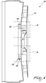
- Figs. 3 and 4 illustrate a section through the pump 10.
- the wear ring 16 is disposed between the impeller 12 and the diffuser 14. Wear ring 16 is disposed at the inlet 34 of the diffuser 14. Wear ring 16 is disposed at the neck 35 of the inlet 34. Wear ring 16 is positioned adjacent the eye 36 of the impeller 12.
- Wear ring 16 is removably coupled to the diffuser 14. Wear ring 16 is removably coupled to the inlet 34 of the diffuser 14. Wear ring 16 is removably coupled to the inner surface of the inlet 34.
- the impeller 12 may be in contact with the wear ring 16 during operation of the pump 10..
- the outer surface of the eye 36 of the impeller 12 may be in slidable contact with the wear ring 16 during operation.
- Wear ring 16 is made of a deformable material. Wear ring 16 is configured to undergo a deformation during mounting to the diffuser 14 and removal from therefrom. In an embodiment, wear ring 16 is made of a plastic material.
- the wear ring 16 has a plurality of radially extending clutch members 18.
- the clutch members 18 are configured to hold a portion of the at least one diffuser 14.
- Clutch members 18 are configured to hold a portion of the inlet 34 of the diffuser 14.
- Clutch members 18 are configured to engage at the inner surface of the neck 35 of the inlet 34.
- Clutch members 18 are configured to engage opposite ends of the inlet 34.
- Fig. 5 illustrates the wear ring 16
- Fig. 6 illustrates a section through the wear ring 16.
- the wear ring 16 is substantially annular.
- Wear ring 16 has an outer surface 30 and an inner surface 32.
- the outer surface 30 may contact the diffuser 14.
- Inner surface 32 may contacts the impeller 12.
- Clutch members 18 extend radially away from the outer surface 30.
- Wear ring 16 has a first side 26 and an opposite second side 27. First and second side 26, 27 extend between the outer surface 30 and the inner surface 32.
- Each clutch member 18 comprises a first and a second tab portions 20, 22.
- the first and second tab portions 20, 22 are spaced apart.
- First and second tab portions 20, 22 are spaced apart on the outer surface 30.
- First and second tab portions 20, 22 are disposed on opposite edges of the outer surface 30.
- Second tab portions 22 extends further from the outer surface 30 than the first tab portions 20.
- First and second tab portions 20, 22 are configured so as to engage opposite ends of the inlet 34 of the diffuser 14.
- first and second tab portions 20, 22 may be vertical relative to the outer surface 30 .
- the first and second tab portions 20, 22 may be substantially perpendicular relative to the outer surface 30.
- Each clutch member 18 may have a substantially U-shaped cross-section formed by the first and second tab portions 20, 22 bordering the outer surface 30.
- the first tab portion 20 is an extension of a tab 24.
- the tab 24 is provided on the first side 26 of the wear ring 16.
- Tab 24 may be formed as a raised platform on the first side 26.
- Tab 24 raises substantially vertically from the first side 26.
- Tab 24 extends across the first side 26.
- Tab 24 has a longitudinal axis D that extends across the first side 26.
- Tab 26 has an inner end 38 opposite to the first tab portion 20. Inner end 38 does not extend over the inner surface 32. Inner end 38 is in line with the inner surface 32. Tab 24 extends over the inner surface 32 through the first tab portion 20.
- First tab portion 20 has a free tab end 40 that is curved across a direction transverse to the longitudinal axis D of the tab 26. Curved free tab end 40 reduces resistance against the inner surface of the inlet 34 of the diffuser 14 during mounting and removal of the wear ring 16.
- Tab 24 has tab sides 42.
- the tab sides 42 may be perpendicular to the first side 26 .Tab sides 42 diverge from the inner end 38 to the first tab portion 20 .
- Tab sides 42 diverge from the inner surface 32 to the outer surface 30 of the wear ring 16 .
- the tab sides 42 have an angle ⁇ that is configured as required. In an embodiment, the tab sides 42 have an angle ⁇ of 10 degrees.
- the wear ring 16 may comprise a number of tabs 24 as required.
- the wear ring 16 may comprises at least two tabs 24 .
- the longitudinal axes D of the two tabs 24 extend radially relative to the wear ring 16 .
- Tabs 24 are mutually angularly spaced on the first side 26 .
- the tabs 24 are mutually angularly spaced at an angle ⁇ that is configured as required.
- the tabs 24 are mutually angularly spaced at an angle ⁇ of 180 degrees.
- the wear ring 16 may comprise three tabs 24 .
- the longitudinal axes D of the three tabs 24 extend radially relative to the wear ring 16 .
- Tabs 24 are mutually angularly spaced on the first side 26 .
- the tabs 24 are mutually angularly spaced at an angle ⁇ that is configured as required.
- the tabs 24 are mutually angularly spaced at an angle ⁇ of 120 degrees.
- the second tab portion 22 is portion of a lip 28 .
- Lip 28 extends laterally from the outer surface 30 of the at least one wear ring 16 .
- the lip 28 extends around the wear ring 16 .
- Lip 28 is configured as a continuous ring around the outer surface 30 .
- Lip 28 has a free lip end 44 that is curved across a direction transverse to the extension of the lip 28. Curved free lip end 44 reduces resistance against the inner surface of the inlet 34 of the diffuser 14 during mounting and removal of the wear ring 16.
- the second tab portion 22 is a discrete structure extending from the outer surface 30.
- Second tab portion 22 extends laterally from the outer surface 30 of the at least one wear ring 16.
- Second tab portion 22 has an end joined to the outer surface and a free lip end 44. Free lip end 44 is curved across a direction transverse to the longitudinal axis of the second tab portion 22. Curved free lip end 44 reduces resistance inner surface of the inlet 34 of the diffuser 14 during mounting and removal of the wear ring 16.
- the wear ring 16 may comprise the same number of second tab portions 22 as tabs 24.
- the longitudinal axes of the second tab portions 22 extend radially relative to the wear ring 16.
- Second tab portions 22 are mutually angularly spaced on the first side 26.
- the wear ring 16 may have a cut-out 21.
- the cut-out 21 may be annular. Cut-out 21 may be positioned between outer surface 30 and an inner surface 32. Cut-out 21 may have an opening on the second side 27. Cut-out 21 may reduce the weight of the wear ring 16.
- Wear ring 16 may have an inclined surface 23 extending between the second side 27 and the inner surface 32.
- Inclined surface 23 may be annular.
- Inclined surface 23 may concentric with the inner surface 32.
- Inclined surface 23 may prevent the wear ring 16 from adhering to the eye 36 of the impeller 12.
- the wear ring 16 is mounted to the diffuser 14 and the clutch member 18 is coupled to the inlet 34 of the diffuser 14. Wear ring 16 is retained in the mounted position by the plurality of clutch members 18 engaging opposite ends of the inlet 34.
- the wear ring 16 is floatingly mounted to the inlet 34.
- the plurality of clutch members 18 may loosely hold the inlet 34.
- the plurality of clutch members 18 engage opposite ends of the inlet 34 with slack to provide for minimal relative movement.
- the wear ring 16 may be capable of angular movement relative to the inlet 34.
- the first tab portion 20 enages a shoulder 48 joined to the neck 35. Shoulder 48 defines the aperture of the inlet 34 into the diffuser 14.
- the plurality of first tab portions 20 is mutually angularly spaced on the shoulder 48 around the aperture of the inlet 34.
- the second tab portion 22 engages a rim 46 of the inlet 34.
- Rim 46 defines the aperture of the inlet 34 to the exterior of the diffuser 14.
- the lip 28 engages the rim 46.
- Clutch member 18 is coupled over the inlet 34 such that the outer surface 30 of the wear ring 16 may contacts the inner surface of the neck 35.
- the first tab portion 20 extends from the tab 24.
- the tab 24 extends axially from the wear ring 16.
- the tab 24 extends axially from the wear ring 16 beyond the shoulder 48.
- At least one tab 24 is configured to abut a vane 50 of the diffuser 14.
- the at least one tab 24 abuts a vane 50 when the wear ring 16 undergoes a rotational movement on the inlet 34.
- the abutting engagement of the tab 24 and the vane 50 serves as an anti-rotation mechanism of the mounted wear ring 16.
- a terminal diffuser 14 does not have a vane 50.
- the tab 24 may be configured to abut a body (not shown) extending from the diffuser 14.
- the body may be soldered to the terminal end of the diffuser 14 and extends from the diffuser.
- Fig. 9 illustrates a portion of the mounted wear ring 16 not having the clutch member 18.
- the outer surface 30 of the wear ring 16 is held against the inner surface of the inlet 34.
- the lip 28 engages the rim 46.
- the side 42 of the tab 24 is available to abut the vane 50 of the diffuser 14.
- the pump 10 is a multi-stage pump comprising a plurality of impellers 12; a plurality of diffusers 14 and a plurality of wear rings 16.
- This disclosure describes a pump 10 having the wear ring 16 that is coupled to the diffuser 14.
- the wear ring 16 is removably coupled to the diffuser 14.
- a worn wear ring 16 is removed with efficiency and ease.
- the clutch members 18 enables the efficient removal and mounting of the wear ring 16. Further, in a multistage pump 10 having a plurality of impellers 12 and diffusers 14, the removably coupled wear rings 16 results in cost savings.
Landscapes
- Engineering & Computer Science (AREA)
- Mechanical Engineering (AREA)
- General Engineering & Computer Science (AREA)
- Structures Of Non-Positive Displacement Pumps (AREA)
Abstract
Description
- This disclosure relates generally to the field of centrifugal pumps and particularly to multistage centrifugal pumps.
- A hydraulic pump is a mechanical source of power that converts mechanical power into flow pressure. The hydraulic pump can be driven by an electrical drive motor. A flow is generated with sufficient power to overcome pressure induced by the load at the hydraulic pump outlet. In operation, the hydraulic pump creates a vacuum at the inlet thereby forcing liquid from the reservoir into the inlet line by mechanical action and delivers the liquid to the outlet and into the hydraulic system.
- Centrifugal pumps are used for a wide variety of liquid pumping applications. Centrifugal pumps, generally, have a impeller to pump liquid by centrifugal force. Centrifugal pumps may be constructed in single stage or multi-stage configurations. Each stage includes a stationary diffuser and a mating, rotating impeller driven by a pump shaft connected to a drive motor. The stages are arranged in "series" to provide an enhanced overall pressure capability.
- Wear rings may be used to absorb thrust, help prevent wear and/or provide a seal-like construction between different parts of the pump. Conventional wearing rings may be formed of metal, ceramic, plastic or carbon materials. The wear rings become consumed during operation and replacement of worn wear rings is required for normal operations.
- In a centrifugal pump, a wear ring may be disposed between the impeller and a diffuser. The wear ring may be contained in a substrate that is coupled to the main body of the diffuser or the pump housing. Generally, a wear ring may be contained in a support structure that is nested or welded to a support surface on the pump housing or the body of the diffuser. Accordingly, in order to replace a worn wear ring, the support structure is first detached from the support surface and the wear ring therein replaced subsequently.
- The present disclosure is directed, at least in part, to improving or overcoming one or more aspects of the prior art system.
- The present disclosure describes a pump comprising at least one impeller; at least one diffuser; and at least one wear ring positioned between the at least one impeller and the at least one diffuser and removably coupled to the diffuser, the at least one wear ring having a plurality of radially extending clutch members wherein the clutch members are configured to hold a portion of the at least one diffuser.
- The foregoing and other features and advantages of the present disclosure will be more fully understood from the following description of various embodiments, when read together with the accompanying drawings, in which:
-
Fig. 1 is a partially sectioned view a pump according to the present disclosure; -
Fig. 2 is an enlarged view of a portion of the pump ofFig. 1 ; -
Fig. 3 is a cross-sectional view of a portion of the pump ofFig. 1 ; -
Fig. 4 is the cross-sectional view of a portion of the pump ofFig. 3 excluding the impeller; -
Fig. 5 is an isometric view a wear ring disposed in the pump ofFig. 1 ; -
Fig. 6 is a cross-sectional view through the wear ring along line C-C' ofFig. 5 ; -
Fig. 7 is a cross-sectional view through a further embodiment of the wear ring along line C-C' ofFig. 5 ; -
Fig. 8 is an enlarged view of part A of the pump ofFig. 4 ; and -
Fig. 9 is an enlarged view of part B of the pump ofFig. 4 . - This disclosure generally relates to a pump having a wear ring removably coupled to a diffuser.
Fig. 1 illustrates apump 10.Fig. 2 illustrates a enlarged view of a portion of thepump 10. Thepump 10 comprises at least oneimpeller 12, at least onediffuser 14 and at least onewear ring 16. -
Figs. 3 and4 illustrate a section through thepump 10. With reference toFigs. 3 and4 , Thewear ring 16 is disposed between theimpeller 12 and thediffuser 14. Wearring 16 is disposed at theinlet 34 of thediffuser 14. Wearring 16 is disposed at theneck 35 of theinlet 34.Wear ring 16 is positioned adjacent theeye 36 of theimpeller 12. -
Wear ring 16 is removably coupled to thediffuser 14.Wear ring 16 is removably coupled to theinlet 34 of thediffuser 14.Wear ring 16 is removably coupled to the inner surface of theinlet 34. Theimpeller 12 may be in contact with thewear ring 16 during operation of thepump 10.. The outer surface of theeye 36 of theimpeller 12 may be in slidable contact with thewear ring 16 during operation. -
Wear ring 16 is made of a deformable material.Wear ring 16 is configured to undergo a deformation during mounting to thediffuser 14 and removal from therefrom. In an embodiment,wear ring 16 is made of a plastic material. - The
wear ring 16 has a plurality of radially extendingclutch members 18. Theclutch members 18 are configured to hold a portion of the at least onediffuser 14. Clutchmembers 18 are configured to hold a portion of theinlet 34 of thediffuser 14. Clutchmembers 18 are configured to engage at the inner surface of theneck 35 of theinlet 34. Clutchmembers 18 are configured to engage opposite ends of theinlet 34. -
Fig. 5 illustrates thewear ring 16 andFig. 6 illustrates a section through thewear ring 16. With reference toFigs. 2 and3 , thewear ring 16 is substantially annular. Wearring 16 has anouter surface 30 and aninner surface 32. Theouter surface 30 may contact thediffuser 14.Inner surface 32 may contacts theimpeller 12. Clutchmembers 18 extend radially away from theouter surface 30. Wear ring 16 has afirst side 26 and an oppositesecond side 27. First andsecond side outer surface 30 and theinner surface 32. - Each
clutch member 18 comprises a first and asecond tab portions second tab portions second tab portions outer surface 30. First andsecond tab portions outer surface 30.Second tab portions 22 extends further from theouter surface 30 than thefirst tab portions 20. First andsecond tab portions inlet 34 of thediffuser 14. - With reference to
Fig. 5 , the first andsecond tab portions second tab portions outer surface 30. Eachclutch member 18 may have a substantially U-shaped cross-section formed by the first andsecond tab portions outer surface 30. - With reference to
Figs. 5 and6 , thefirst tab portion 20 is an extension of atab 24. Thetab 24 is provided on thefirst side 26 of thewear ring 16.Tab 24 may be formed as a raised platform on thefirst side 26.Tab 24 raises substantially vertically from thefirst side 26.Tab 24 extends across thefirst side 26.Tab 24 has a longitudinal axis D that extends across thefirst side 26. -
Tab 26 has aninner end 38 opposite to thefirst tab portion 20.Inner end 38 does not extend over theinner surface 32.Inner end 38 is in line with theinner surface 32.Tab 24 extends over theinner surface 32 through thefirst tab portion 20.First tab portion 20 has afree tab end 40 that is curved across a direction transverse to the longitudinal axis D of thetab 26. Curvedfree tab end 40 reduces resistance against the inner surface of theinlet 34 of thediffuser 14 during mounting and removal of thewear ring 16. -
Tab 24 has tab sides 42. The tab sides 42 may be perpendicular to the first side 26.Tab sides 42 diverge from theinner end 38 to thefirst tab portion 20. Tab sides 42 diverge from theinner surface 32 to theouter surface 30 of thewear ring 16. The tab sides 42 have an angle α that is configured as required. In an embodiment, the tab sides 42 have an angle α of 10 degrees. - The
wear ring 16 may comprise a number oftabs 24 as required. In an embodiment, thewear ring 16 may comprises at least twotabs 24. The longitudinal axes D of the twotabs 24 extend radially relative to thewear ring 16.Tabs 24 are mutually angularly spaced on thefirst side 26. Thetabs 24 are mutually angularly spaced at an angle β that is configured as required. Thetabs 24 are mutually angularly spaced at an angle β of 180 degrees. - In a further embodiment, the
wear ring 16 may comprise threetabs 24. The longitudinal axes D of the threetabs 24 extend radially relative to thewear ring 16.Tabs 24 are mutually angularly spaced on thefirst side 26. Thetabs 24 are mutually angularly spaced at an angle β that is configured as required. Thetabs 24 are mutually angularly spaced at an angle β of 120 degrees. - The
second tab portion 22 is portion of alip 28.Lip 28 extends laterally from theouter surface 30 of the at least onewear ring 16. Thelip 28 extends around thewear ring 16.Lip 28 is configured as a continuous ring around theouter surface 30.Lip 28 has afree lip end 44 that is curved across a direction transverse to the extension of thelip 28. Curvedfree lip end 44 reduces resistance against the inner surface of theinlet 34 of thediffuser 14 during mounting and removal of thewear ring 16. - In an embodiment, the
second tab portion 22 is a discrete structure extending from theouter surface 30.Second tab portion 22 extends laterally from theouter surface 30 of the at least onewear ring 16.Second tab portion 22 has an end joined to the outer surface and afree lip end 44.Free lip end 44 is curved across a direction transverse to the longitudinal axis of thesecond tab portion 22. Curvedfree lip end 44 reduces resistance inner surface of theinlet 34 of thediffuser 14 during mounting and removal of thewear ring 16. - The
wear ring 16 may comprise the same number ofsecond tab portions 22 astabs 24. The longitudinal axes of thesecond tab portions 22 extend radially relative to thewear ring 16.Second tab portions 22 are mutually angularly spaced on thefirst side 26. - With reference to
Fig. 7 , in an embodiment, thewear ring 16 may have a cut-out 21. The cut-out 21 may be annular. Cut-out 21 may be positioned betweenouter surface 30 and aninner surface 32. Cut-out 21 may have an opening on thesecond side 27. Cut-out 21 may reduce the weight of thewear ring 16. -
Wear ring 16 may have aninclined surface 23 extending between thesecond side 27 and theinner surface 32.Inclined surface 23 may be annular.Inclined surface 23 may concentric with theinner surface 32.Inclined surface 23 may prevent thewear ring 16 from adhering to theeye 36 of theimpeller 12. - With reference to
Fig. 8 , thewear ring 16 is mounted to thediffuser 14 and theclutch member 18 is coupled to theinlet 34 of thediffuser 14.Wear ring 16 is retained in the mounted position by the plurality ofclutch members 18 engaging opposite ends of theinlet 34. In an embodiment, thewear ring 16 is floatingly mounted to theinlet 34. The plurality ofclutch members 18 may loosely hold theinlet 34. The plurality ofclutch members 18 engage opposite ends of theinlet 34 with slack to provide for minimal relative movement. Thewear ring 16 may be capable of angular movement relative to theinlet 34. Thefirst tab portion 20 enages ashoulder 48 joined to theneck 35.Shoulder 48 defines the aperture of theinlet 34 into thediffuser 14. The plurality offirst tab portions 20 is mutually angularly spaced on theshoulder 48 around the aperture of theinlet 34. - The
second tab portion 22 engages arim 46 of theinlet 34.Rim 46 defines the aperture of theinlet 34 to the exterior of thediffuser 14. In an embodiment, thelip 28 engages therim 46.Clutch member 18 is coupled over theinlet 34 such that theouter surface 30 of thewear ring 16 may contacts the inner surface of theneck 35. - The
first tab portion 20 extends from thetab 24. Thetab 24 extends axially from thewear ring 16. Thetab 24 extends axially from thewear ring 16 beyond theshoulder 48. At least onetab 24 is configured to abut avane 50 of thediffuser 14. The at least onetab 24 abuts avane 50 when thewear ring 16 undergoes a rotational movement on theinlet 34. The abutting engagement of thetab 24 and thevane 50 serves as an anti-rotation mechanism of the mountedwear ring 16. - In an embodiment, a
terminal diffuser 14 does not have avane 50. Thetab 24 may be configured to abut a body (not shown) extending from thediffuser 14. The body may be soldered to the terminal end of thediffuser 14 and extends from the diffuser. -
Fig. 9 illustrates a portion of the mountedwear ring 16 not having theclutch member 18. Theouter surface 30 of thewear ring 16 is held against the inner surface of theinlet 34. In an embodiment, thelip 28 engages therim 46. Theside 42 of thetab 24 is available to abut thevane 50 of thediffuser 14. - In an embodiment, the
pump 10 is a multi-stage pump comprising a plurality ofimpellers 12; a plurality ofdiffusers 14 and a plurality of wear rings 16. - The skilled person would appreciate that foregoing embodiments may be modified or combined to obtain the
pump 10 of the present disclosure. - This disclosure describes a
pump 10 having thewear ring 16 that is coupled to thediffuser 14. Thewear ring 16 is removably coupled to thediffuser 14. Aworn wear ring 16 is removed with efficiency and ease. Theclutch members 18 enables the efficient removal and mounting of thewear ring 16. Further, in amultistage pump 10 having a plurality ofimpellers 12 anddiffusers 14, the removably coupled wear rings 16 results in cost savings. - Accordingly, this disclosure includes all modifications and equivalents of the subject matter recited in the claims appended hereto as permitted by applicable law. Moreover, any combination of the above-described elements in all possible variations thereof is encompassed by the disclosure unless otherwise indicated herein.
- Where technical features mentioned in any claim are followed by reference signs, the reference signs have been included for the sole purpose of increasing the intelligibility of the claims and accordingly, neither the reference signs nor their absence have any limiting effect on the technical features as described above or on the scope of any claim elements.
- One skilled in the art will realise the disclosure may be embodied in other specific forms without departing from the disclosure or essential characteristics thereof. The foregoing embodiments are therefore to be considered in all respects illustrative rather than limiting of the disclosure described herein. Scope of the invention is thus indicated by the appended claims, rather than the foregoing description, and all changes that come within the meaning and range of equivalence of the claims are therefore intended to be embraced therein.
Claims (10)
- A pump (10) comprising:at least one impeller (12);at least one diffuser (14); andat least one wear ring (16) positioned between the at least one impeller (12) and the at least one diffuser (14) and removably coupled to the diffuser (14), the at least one wear ring (16) having a plurality of radially extending clutch members (18) wherein the clutch members (18) are configured to hold a portion of the at least one diffuser (14).
- The pump (10) of claim 1 wherein the clutch member (18) comprises a first and a second tab portions (20, 22) wherein the first and second tab portions (20, 22) are spaced art.
- The pump (10) of claim 2 wherein the first tab portion (20) is an extension of a tab (24), first tab portion (20) extending from a first side (26) of the at least one wear ring (16).
- The pump (10) of claim 3 wherein the at least one wear ring (16) comprises three tabs (24) mutually angularly spaced on the first side (26).
- The pump (10) of claim 4 wherein the tabs (24) are mutually angularly spaced at an angle (α) of 120 degrees.
- The pump (10) of any one of claims 2 to 5 wherein the second tab portion (22) is portion of a lip (28) extending laterally from an outer surface (30) of the at least one wear ring (16).
- The pump (10) of claim 6 wherein the lip (28) extends around the at least one wear ring (16).
- The pump (10) of any one of preceding claims wherein the at least one wear ring (16) is composed of a deformable material.
- The pump (10) of any one of preceding claims wherein the at least one impeller (12) contacts the inner surface (32) of the at least one wear ring (16).
- The pump (10) of any one of preceding claims wherein the pump (10) is a multi-stage pump comprising a plurality of impellers (12); a plurality of diffusers (14) and a plurality of wear rings (16).
Priority Applications (7)
| Application Number | Priority Date | Filing Date | Title |
|---|---|---|---|
| EP17193189.2A EP3460253B1 (en) | 2017-09-26 | 2017-09-26 | Pump with a wear ring |
| JP2020517178A JP7174754B2 (en) | 2017-09-26 | 2018-09-25 | pump with wear ring |
| AU2018340335A AU2018340335B2 (en) | 2017-09-26 | 2018-09-25 | Pump with a wear ring |
| US16/647,588 US11236750B2 (en) | 2017-09-26 | 2018-09-25 | Pump with a wear ring |
| PCT/EP2018/075975 WO2019063552A1 (en) | 2017-09-26 | 2018-09-25 | Pump with a wear ring |
| CN201880053474.9A CN111033054B (en) | 2017-09-26 | 2018-09-25 | Pumps with wear rings |
| CA3070527A CA3070527A1 (en) | 2017-09-26 | 2018-09-25 | Pump with a wear ring |
Applications Claiming Priority (1)
| Application Number | Priority Date | Filing Date | Title |
|---|---|---|---|
| EP17193189.2A EP3460253B1 (en) | 2017-09-26 | 2017-09-26 | Pump with a wear ring |
Publications (2)
| Publication Number | Publication Date |
|---|---|
| EP3460253A1 true EP3460253A1 (en) | 2019-03-27 |
| EP3460253B1 EP3460253B1 (en) | 2025-03-19 |
Family
ID=59969069
Family Applications (1)
| Application Number | Title | Priority Date | Filing Date |
|---|---|---|---|
| EP17193189.2A Active EP3460253B1 (en) | 2017-09-26 | 2017-09-26 | Pump with a wear ring |
Country Status (7)
| Country | Link |
|---|---|
| US (1) | US11236750B2 (en) |
| EP (1) | EP3460253B1 (en) |
| JP (1) | JP7174754B2 (en) |
| CN (1) | CN111033054B (en) |
| AU (1) | AU2018340335B2 (en) |
| CA (1) | CA3070527A1 (en) |
| WO (1) | WO2019063552A1 (en) |
Families Citing this family (4)
| Publication number | Priority date | Publication date | Assignee | Title |
|---|---|---|---|---|
| ES3061428T3 (en) | 2019-05-29 | 2026-04-01 | Fluid Handling Llc | Bearing-less vertical pump |
| WO2022166204A1 (en) * | 2021-02-04 | 2022-08-11 | 钱江集团温岭正峰动力有限公司 | Centrifugal pump |
| CN114857033B (en) * | 2021-02-04 | 2025-02-28 | 钱江集团温岭正峰动力有限公司 | Centrifugal Pumps |
| CN114857031B (en) * | 2021-02-04 | 2025-02-28 | 钱江集团温岭正峰动力有限公司 | Centrifugal Pumps |
Citations (5)
| Publication number | Priority date | Publication date | Assignee | Title |
|---|---|---|---|---|
| GB1110660A (en) * | 1966-05-20 | 1968-04-24 | Sumo Pumps Ltd | Improvements relating to sealing means for centrifugal pumps |
| EP0257358A2 (en) * | 1986-08-08 | 1988-03-02 | LOWARA S.p.A. | Hydraulic sealing ring on the inlet of the impeller in single-stage and multistage pumps |
| DE19916370A1 (en) * | 1999-04-13 | 2000-10-19 | Iveco Magirus | Centrifugal pump |
| US20060269404A1 (en) * | 2005-05-26 | 2006-11-30 | Franklin Electric Co., Inc. | Multistage pump |
| EP3181909A1 (en) * | 2015-12-14 | 2017-06-21 | Wilo Se | Compact sealing ring unit |
Family Cites Families (8)
| Publication number | Priority date | Publication date | Assignee | Title |
|---|---|---|---|---|
| US2644403A (en) * | 1952-03-05 | 1953-07-07 | Ingersoll Rand Co | Device for preventing clogging in centrifugal pumps |
| JPS60178998A (en) | 1984-02-27 | 1985-09-12 | Hitachi Ltd | Wear ring fixing device for high temperature pump |
| US5295786A (en) * | 1990-12-27 | 1994-03-22 | Ebara Corporation | Liner ring for a pump |
| JPH07224783A (en) | 1994-02-15 | 1995-08-22 | Ebara Corp | Liner ring |
| RU2213271C2 (en) | 1999-05-31 | 2003-09-27 | ОАО "Ливенский завод погружных насосов" | Centrifugal impeller |
| JP4532142B2 (en) * | 2003-12-22 | 2010-08-25 | 株式会社荏原製作所 | Fluid machinery sealing mechanism or centrifugal pump |
| JP4456062B2 (en) * | 2005-12-16 | 2010-04-28 | 株式会社酉島製作所 | Fluid machinery sealing device |
| DE102012218606A1 (en) | 2012-10-12 | 2014-04-17 | Ksb Aktiengesellschaft | Split ring with self-regulating throttle gap |
-
2017
- 2017-09-26 EP EP17193189.2A patent/EP3460253B1/en active Active
-
2018
- 2018-09-25 JP JP2020517178A patent/JP7174754B2/en not_active Expired - Fee Related
- 2018-09-25 AU AU2018340335A patent/AU2018340335B2/en not_active Ceased
- 2018-09-25 WO PCT/EP2018/075975 patent/WO2019063552A1/en not_active Ceased
- 2018-09-25 CN CN201880053474.9A patent/CN111033054B/en active Active
- 2018-09-25 US US16/647,588 patent/US11236750B2/en not_active Expired - Fee Related
- 2018-09-25 CA CA3070527A patent/CA3070527A1/en active Pending
Patent Citations (5)
| Publication number | Priority date | Publication date | Assignee | Title |
|---|---|---|---|---|
| GB1110660A (en) * | 1966-05-20 | 1968-04-24 | Sumo Pumps Ltd | Improvements relating to sealing means for centrifugal pumps |
| EP0257358A2 (en) * | 1986-08-08 | 1988-03-02 | LOWARA S.p.A. | Hydraulic sealing ring on the inlet of the impeller in single-stage and multistage pumps |
| DE19916370A1 (en) * | 1999-04-13 | 2000-10-19 | Iveco Magirus | Centrifugal pump |
| US20060269404A1 (en) * | 2005-05-26 | 2006-11-30 | Franklin Electric Co., Inc. | Multistage pump |
| EP3181909A1 (en) * | 2015-12-14 | 2017-06-21 | Wilo Se | Compact sealing ring unit |
Also Published As
| Publication number | Publication date |
|---|---|
| US20200232467A1 (en) | 2020-07-23 |
| CA3070527A1 (en) | 2019-04-04 |
| EP3460253B1 (en) | 2025-03-19 |
| US11236750B2 (en) | 2022-02-01 |
| AU2018340335A1 (en) | 2020-02-13 |
| JP7174754B2 (en) | 2022-11-17 |
| WO2019063552A1 (en) | 2019-04-04 |
| AU2018340335B2 (en) | 2024-02-01 |
| CN111033054B (en) | 2022-07-26 |
| CN111033054A (en) | 2020-04-17 |
| JP2020535346A (en) | 2020-12-03 |
Similar Documents
| Publication | Publication Date | Title |
|---|---|---|
| AU2018340335B2 (en) | Pump with a wear ring | |
| US5531564A (en) | Centrifugal pump | |
| KR101987930B1 (en) | Fuel pump assembly | |
| EP2971793B1 (en) | Seal for a centrifugal pump | |
| JPH0718436B2 (en) | Steel plate intermediate casing and multi-stage pump using the intermediate casing | |
| US11118508B2 (en) | Variable displacement turbocharger | |
| US10544787B2 (en) | Pump device | |
| AU2015255274B2 (en) | Axially split pump | |
| EP2136084A2 (en) | Centrifugal pump with segmented diffuser | |
| CN108869397B (en) | Volute for centrifugal pump and centrifugal pump | |
| CN108350949A (en) | Shaft coupling and pump | |
| RU2690597C2 (en) | Pump with axial connector | |
| US6398493B1 (en) | Floatable impeller for multistage metal working pump | |
| JP7437540B2 (en) | Removable integrated wear ring impeller skirt | |
| CN112628152A (en) | Pump for conveying fluids | |
| KR101677072B1 (en) | Casing ring having wear ring, and double suction type centrifugal pump including this same | |
| CN102575680B (en) | Submerged centrifugal electric pump | |
| CN120159776B (en) | Multistage impeller pump unit system | |
| KR20150111069A (en) | Oil pump housing for automatic transmission | |
| EP1469204A1 (en) | Impeller | |
| CN108799132B (en) | Impeller pump | |
| CN104074801B (en) | Multistage pump | |
| EP4692563A1 (en) | Casing for centrifugal pump | |
| US20060067811A1 (en) | Impeller with an abradable tip | |
| RU2234620C1 (en) | Submersible multistage centrifugal pump |
Legal Events
| Date | Code | Title | Description |
|---|---|---|---|
| PUAI | Public reference made under article 153(3) epc to a published international application that has entered the european phase |
Free format text: ORIGINAL CODE: 0009012 |
|
| STAA | Information on the status of an ep patent application or granted ep patent |
Free format text: STATUS: THE APPLICATION HAS BEEN PUBLISHED |
|
| AK | Designated contracting states |
Kind code of ref document: A1 Designated state(s): AL AT BE BG CH CY CZ DE DK EE ES FI FR GB GR HR HU IE IS IT LI LT LU LV MC MK MT NL NO PL PT RO RS SE SI SK SM TR |
|
| AX | Request for extension of the european patent |
Extension state: BA ME |
|
| STAA | Information on the status of an ep patent application or granted ep patent |
Free format text: STATUS: REQUEST FOR EXAMINATION WAS MADE |
|
| 17P | Request for examination filed |
Effective date: 20190418 |
|
| RBV | Designated contracting states (corrected) |
Designated state(s): AL AT BE BG CH CY CZ DE DK EE ES FI FR GB GR HR HU IE IS IT LI LT LU LV MC MK MT NL NO PL PT RO RS SE SI SK SM TR |
|
| RAP1 | Party data changed (applicant data changed or rights of an application transferred) |
Owner name: XYLEM EUROPE GMBH |
|
| STAA | Information on the status of an ep patent application or granted ep patent |
Free format text: STATUS: EXAMINATION IS IN PROGRESS |
|
| 17Q | First examination report despatched |
Effective date: 20211221 |
|
| GRAP | Despatch of communication of intention to grant a patent |
Free format text: ORIGINAL CODE: EPIDOSNIGR1 |
|
| STAA | Information on the status of an ep patent application or granted ep patent |
Free format text: STATUS: GRANT OF PATENT IS INTENDED |
|
| INTG | Intention to grant announced |
Effective date: 20241203 |
|
| GRAS | Grant fee paid |
Free format text: ORIGINAL CODE: EPIDOSNIGR3 |
|
| GRAA | (expected) grant |
Free format text: ORIGINAL CODE: 0009210 |
|
| STAA | Information on the status of an ep patent application or granted ep patent |
Free format text: STATUS: THE PATENT HAS BEEN GRANTED |
|
| AK | Designated contracting states |
Kind code of ref document: B1 Designated state(s): AL AT BE BG CH CY CZ DE DK EE ES FI FR GB GR HR HU IE IS IT LI LT LU LV MC MK MT NL NO PL PT RO RS SE SI SK SM TR |
|
| REG | Reference to a national code |
Ref country code: GB Ref legal event code: FG4D |
|
| REG | Reference to a national code |
Ref country code: CH Ref legal event code: EP |
|
| REG | Reference to a national code |
Ref country code: DE Ref legal event code: R096 Ref document number: 602017088383 Country of ref document: DE |
|
| REG | Reference to a national code |
Ref country code: IE Ref legal event code: FG4D |
|
| PG25 | Lapsed in a contracting state [announced via postgrant information from national office to epo] |
Ref country code: RS Free format text: LAPSE BECAUSE OF FAILURE TO SUBMIT A TRANSLATION OF THE DESCRIPTION OR TO PAY THE FEE WITHIN THE PRESCRIBED TIME-LIMIT Effective date: 20250619 |
|
| PG25 | Lapsed in a contracting state [announced via postgrant information from national office to epo] |
Ref country code: FI Free format text: LAPSE BECAUSE OF FAILURE TO SUBMIT A TRANSLATION OF THE DESCRIPTION OR TO PAY THE FEE WITHIN THE PRESCRIBED TIME-LIMIT Effective date: 20250319 |
|
| REG | Reference to a national code |
Ref country code: LT Ref legal event code: MG9D |
|
| PG25 | Lapsed in a contracting state [announced via postgrant information from national office to epo] |
Ref country code: NO Free format text: LAPSE BECAUSE OF FAILURE TO SUBMIT A TRANSLATION OF THE DESCRIPTION OR TO PAY THE FEE WITHIN THE PRESCRIBED TIME-LIMIT Effective date: 20250619 |
|
| PG25 | Lapsed in a contracting state [announced via postgrant information from national office to epo] |
Ref country code: HR Free format text: LAPSE BECAUSE OF FAILURE TO SUBMIT A TRANSLATION OF THE DESCRIPTION OR TO PAY THE FEE WITHIN THE PRESCRIBED TIME-LIMIT Effective date: 20250319 |
|
| PG25 | Lapsed in a contracting state [announced via postgrant information from national office to epo] |
Ref country code: LV Free format text: LAPSE BECAUSE OF FAILURE TO SUBMIT A TRANSLATION OF THE DESCRIPTION OR TO PAY THE FEE WITHIN THE PRESCRIBED TIME-LIMIT Effective date: 20250319 |
|
| PG25 | Lapsed in a contracting state [announced via postgrant information from national office to epo] |
Ref country code: GR Free format text: LAPSE BECAUSE OF FAILURE TO SUBMIT A TRANSLATION OF THE DESCRIPTION OR TO PAY THE FEE WITHIN THE PRESCRIBED TIME-LIMIT Effective date: 20250620 Ref country code: BG Free format text: LAPSE BECAUSE OF FAILURE TO SUBMIT A TRANSLATION OF THE DESCRIPTION OR TO PAY THE FEE WITHIN THE PRESCRIBED TIME-LIMIT Effective date: 20250319 |
|
| REG | Reference to a national code |
Ref country code: NL Ref legal event code: MP Effective date: 20250319 |
|
| REG | Reference to a national code |
Ref country code: AT Ref legal event code: MK05 Ref document number: 1777157 Country of ref document: AT Kind code of ref document: T Effective date: 20250319 |
|
| PG25 | Lapsed in a contracting state [announced via postgrant information from national office to epo] |
Ref country code: NL Free format text: LAPSE BECAUSE OF FAILURE TO SUBMIT A TRANSLATION OF THE DESCRIPTION OR TO PAY THE FEE WITHIN THE PRESCRIBED TIME-LIMIT Effective date: 20250319 |
|
| PG25 | Lapsed in a contracting state [announced via postgrant information from national office to epo] |
Ref country code: SE Free format text: LAPSE BECAUSE OF FAILURE TO SUBMIT A TRANSLATION OF THE DESCRIPTION OR TO PAY THE FEE WITHIN THE PRESCRIBED TIME-LIMIT Effective date: 20250319 |
|
| PG25 | Lapsed in a contracting state [announced via postgrant information from national office to epo] |
Ref country code: SM Free format text: LAPSE BECAUSE OF FAILURE TO SUBMIT A TRANSLATION OF THE DESCRIPTION OR TO PAY THE FEE WITHIN THE PRESCRIBED TIME-LIMIT Effective date: 20250319 |
|
| PG25 | Lapsed in a contracting state [announced via postgrant information from national office to epo] |
Ref country code: ES Free format text: LAPSE BECAUSE OF FAILURE TO SUBMIT A TRANSLATION OF THE DESCRIPTION OR TO PAY THE FEE WITHIN THE PRESCRIBED TIME-LIMIT Effective date: 20250319 Ref country code: PT Free format text: LAPSE BECAUSE OF FAILURE TO SUBMIT A TRANSLATION OF THE DESCRIPTION OR TO PAY THE FEE WITHIN THE PRESCRIBED TIME-LIMIT Effective date: 20250721 |
|
| PG25 | Lapsed in a contracting state [announced via postgrant information from national office to epo] |
Ref country code: PL Free format text: LAPSE BECAUSE OF FAILURE TO SUBMIT A TRANSLATION OF THE DESCRIPTION OR TO PAY THE FEE WITHIN THE PRESCRIBED TIME-LIMIT Effective date: 20250319 |
|
| PGFP | Annual fee paid to national office [announced via postgrant information from national office to epo] |
Ref country code: IT Payment date: 20250919 Year of fee payment: 9 |
|
| PGFP | Annual fee paid to national office [announced via postgrant information from national office to epo] |
Ref country code: GB Payment date: 20250929 Year of fee payment: 9 |
|
| PG25 | Lapsed in a contracting state [announced via postgrant information from national office to epo] |
Ref country code: AT Free format text: LAPSE BECAUSE OF FAILURE TO SUBMIT A TRANSLATION OF THE DESCRIPTION OR TO PAY THE FEE WITHIN THE PRESCRIBED TIME-LIMIT Effective date: 20250319 |
|
| PG25 | Lapsed in a contracting state [announced via postgrant information from national office to epo] |
Ref country code: CZ Free format text: LAPSE BECAUSE OF FAILURE TO SUBMIT A TRANSLATION OF THE DESCRIPTION OR TO PAY THE FEE WITHIN THE PRESCRIBED TIME-LIMIT Effective date: 20250319 Ref country code: EE Free format text: LAPSE BECAUSE OF FAILURE TO SUBMIT A TRANSLATION OF THE DESCRIPTION OR TO PAY THE FEE WITHIN THE PRESCRIBED TIME-LIMIT Effective date: 20250319 |
|
| PG25 | Lapsed in a contracting state [announced via postgrant information from national office to epo] |
Ref country code: RO Free format text: LAPSE BECAUSE OF FAILURE TO SUBMIT A TRANSLATION OF THE DESCRIPTION OR TO PAY THE FEE WITHIN THE PRESCRIBED TIME-LIMIT Effective date: 20250319 |
|
| PG25 | Lapsed in a contracting state [announced via postgrant information from national office to epo] |
Ref country code: SK Free format text: LAPSE BECAUSE OF FAILURE TO SUBMIT A TRANSLATION OF THE DESCRIPTION OR TO PAY THE FEE WITHIN THE PRESCRIBED TIME-LIMIT Effective date: 20250319 |
|
| PG25 | Lapsed in a contracting state [announced via postgrant information from national office to epo] |
Ref country code: IS Free format text: LAPSE BECAUSE OF FAILURE TO SUBMIT A TRANSLATION OF THE DESCRIPTION OR TO PAY THE FEE WITHIN THE PRESCRIBED TIME-LIMIT Effective date: 20250719 |
|
| REG | Reference to a national code |
Ref country code: DE Ref legal event code: R097 Ref document number: 602017088383 Country of ref document: DE |
|
| PG25 | Lapsed in a contracting state [announced via postgrant information from national office to epo] |
Ref country code: DK Free format text: LAPSE BECAUSE OF FAILURE TO SUBMIT A TRANSLATION OF THE DESCRIPTION OR TO PAY THE FEE WITHIN THE PRESCRIBED TIME-LIMIT Effective date: 20250319 |
|
| PLBE | No opposition filed within time limit |
Free format text: ORIGINAL CODE: 0009261 |
|
| STAA | Information on the status of an ep patent application or granted ep patent |
Free format text: STATUS: NO OPPOSITION FILED WITHIN TIME LIMIT |
|
| REG | Reference to a national code |
Ref country code: CH Ref legal event code: L10 Free format text: ST27 STATUS EVENT CODE: U-0-0-L10-L00 (AS PROVIDED BY THE NATIONAL OFFICE) Effective date: 20260128 |
|
| 26N | No opposition filed |
Effective date: 20251222 |
|
| REG | Reference to a national code |
Ref country code: DE Ref legal event code: R119 Ref document number: 602017088383 Country of ref document: DE |
|
| REG | Reference to a national code |
Ref country code: CH Ref legal event code: H13 Free format text: ST27 STATUS EVENT CODE: U-0-0-H10-H13 (AS PROVIDED BY THE NATIONAL OFFICE) Effective date: 20260504 |
|
| PG25 | Lapsed in a contracting state [announced via postgrant information from national office to epo] |
Ref country code: LU Free format text: LAPSE BECAUSE OF NON-PAYMENT OF DUE FEES Effective date: 20250926 |
|
| REG | Reference to a national code |
Ref country code: BE Ref legal event code: MM Effective date: 20250930 |
|
| PG25 | Lapsed in a contracting state [announced via postgrant information from national office to epo] |
Ref country code: LT Free format text: LAPSE BECAUSE OF FAILURE TO SUBMIT A TRANSLATION OF THE DESCRIPTION OR TO PAY THE FEE WITHIN THE PRESCRIBED TIME-LIMIT Effective date: 20250319 |
|
| PG25 | Lapsed in a contracting state [announced via postgrant information from national office to epo] |
Ref country code: MC Free format text: LAPSE BECAUSE OF FAILURE TO SUBMIT A TRANSLATION OF THE DESCRIPTION OR TO PAY THE FEE WITHIN THE PRESCRIBED TIME-LIMIT Effective date: 20250319 |
|
| PG25 | Lapsed in a contracting state [announced via postgrant information from national office to epo] |
Ref country code: DE Free format text: LAPSE BECAUSE OF NON-PAYMENT OF DUE FEES Effective date: 20260401 |
|
| PG25 | Lapsed in a contracting state [announced via postgrant information from national office to epo] |
Ref country code: CH Free format text: LAPSE BECAUSE OF NON-PAYMENT OF DUE FEES Effective date: 20250930 Ref country code: IE Free format text: LAPSE BECAUSE OF NON-PAYMENT OF DUE FEES Effective date: 20250926 Ref country code: BE Free format text: LAPSE BECAUSE OF NON-PAYMENT OF DUE FEES Effective date: 20250930 |
|
| PG25 | Lapsed in a contracting state [announced via postgrant information from national office to epo] |
Ref country code: FR Free format text: LAPSE BECAUSE OF NON-PAYMENT OF DUE FEES Effective date: 20250930 |