EP3460217B1 - Verteiler mit mehreren flüssigkeitskreisläufen - Google Patents
Verteiler mit mehreren flüssigkeitskreisläufen Download PDFInfo
- Publication number
- EP3460217B1 EP3460217B1 EP18196247.3A EP18196247A EP3460217B1 EP 3460217 B1 EP3460217 B1 EP 3460217B1 EP 18196247 A EP18196247 A EP 18196247A EP 3460217 B1 EP3460217 B1 EP 3460217B1
- Authority
- EP
- European Patent Office
- Prior art keywords
- passage
- manifold
- annular
- manifold body
- recited
- Prior art date
- Legal status (The legal status is an assumption and is not a legal conclusion. Google has not performed a legal analysis and makes no representation as to the accuracy of the status listed.)
- Active
Links
Images



Classifications
-
- F—MECHANICAL ENGINEERING; LIGHTING; HEATING; WEAPONS; BLASTING
- F02—COMBUSTION ENGINES; HOT-GAS OR COMBUSTION-PRODUCT ENGINE PLANTS
- F02C—GAS-TURBINE PLANTS; AIR INTAKES FOR JET-PROPULSION PLANTS; CONTROLLING FUEL SUPPLY IN AIR-BREATHING JET-PROPULSION PLANTS
- F02C7/00—Features, components parts, details or accessories, not provided for in, or of interest apart form groups F02C1/00 - F02C6/00; Air intakes for jet-propulsion plants
- F02C7/22—Fuel supply systems
- F02C7/222—Fuel flow conduits, e.g. manifolds
-
- F—MECHANICAL ENGINEERING; LIGHTING; HEATING; WEAPONS; BLASTING
- F23—COMBUSTION APPARATUS; COMBUSTION PROCESSES
- F23R—GENERATING COMBUSTION PRODUCTS OF HIGH PRESSURE OR HIGH VELOCITY, e.g. GAS-TURBINE COMBUSTION CHAMBERS
- F23R3/00—Continuous combustion chambers using liquid or gaseous fuel
- F23R3/02—Continuous combustion chambers using liquid or gaseous fuel characterised by the air-flow or gas-flow configuration
- F23R3/04—Air inlet arrangements
- F23R3/10—Air inlet arrangements for primary air
-
- F—MECHANICAL ENGINEERING; LIGHTING; HEATING; WEAPONS; BLASTING
- F23—COMBUSTION APPARATUS; COMBUSTION PROCESSES
- F23R—GENERATING COMBUSTION PRODUCTS OF HIGH PRESSURE OR HIGH VELOCITY, e.g. GAS-TURBINE COMBUSTION CHAMBERS
- F23R3/00—Continuous combustion chambers using liquid or gaseous fuel
- F23R3/28—Continuous combustion chambers using liquid or gaseous fuel characterised by the fuel supply
- F23R3/34—Feeding into different combustion zones
- F23R3/346—Feeding into different combustion zones for staged combustion
-
- F—MECHANICAL ENGINEERING; LIGHTING; HEATING; WEAPONS; BLASTING
- F23—COMBUSTION APPARATUS; COMBUSTION PROCESSES
- F23R—GENERATING COMBUSTION PRODUCTS OF HIGH PRESSURE OR HIGH VELOCITY, e.g. GAS-TURBINE COMBUSTION CHAMBERS
- F23R3/00—Continuous combustion chambers using liquid or gaseous fuel
- F23R3/28—Continuous combustion chambers using liquid or gaseous fuel characterised by the fuel supply
- F23R3/36—Supply of different fuels
-
- F—MECHANICAL ENGINEERING; LIGHTING; HEATING; WEAPONS; BLASTING
- F05—INDEXING SCHEMES RELATING TO ENGINES OR PUMPS IN VARIOUS SUBCLASSES OF CLASSES F01-F04
- F05D—INDEXING SCHEME FOR ASPECTS RELATING TO NON-POSITIVE-DISPLACEMENT MACHINES OR ENGINES, GAS-TURBINES OR JET-PROPULSION PLANTS
- F05D2220/00—Application
- F05D2220/30—Application in turbines
- F05D2220/32—Application in turbines in gas turbines
-
- F—MECHANICAL ENGINEERING; LIGHTING; HEATING; WEAPONS; BLASTING
- F05—INDEXING SCHEMES RELATING TO ENGINES OR PUMPS IN VARIOUS SUBCLASSES OF CLASSES F01-F04
- F05D—INDEXING SCHEME FOR ASPECTS RELATING TO NON-POSITIVE-DISPLACEMENT MACHINES OR ENGINES, GAS-TURBINES OR JET-PROPULSION PLANTS
- F05D2240/00—Components
- F05D2240/35—Combustors or associated equipment
-
- F—MECHANICAL ENGINEERING; LIGHTING; HEATING; WEAPONS; BLASTING
- F23—COMBUSTION APPARATUS; COMBUSTION PROCESSES
- F23R—GENERATING COMBUSTION PRODUCTS OF HIGH PRESSURE OR HIGH VELOCITY, e.g. GAS-TURBINE COMBUSTION CHAMBERS
- F23R2900/00—Special features of, or arrangements for continuous combustion chambers; Combustion processes therefor
- F23R2900/00012—Details of sealing devices
Definitions
- the present disclosure relates to fluid manifolds, and more particularly to manifolds such as used in gas turbine engines.
- Fuel manifolds can route multiple different types of fuel to suitable injectors within the gas turbine engine.
- Traditional fuel manifolds are relatively complicated and bulky, especially when multiple fuels must be routed to the engine while remaining in fluid isolation from one another en route.
- the complicated nature of fuel manifolds is compounded if it is desired to utilize staged fuel injection, e.g., for improved turn down ratios.
- EP 3348813 A1 which is prior art under Article 54(3) EPC only, discloses a fluid manifold including a manifold body having a first annular passage defined between a first wall of the manifold body and a second wall of the manifold body, wherein the second wall is radially inward from the first wall.
- a second annular passage is nested radially inward of the first annular passage, wherein the second annular passage is defined between the second wall of the manifold body and a third wall of the manifold body radially inward from the second wall of the manifold body.
- WO 2014/133406 discloses a turbine combustor including a head end portion having a head end chamber.
- the head end portion includes an exhaust gas path, a fuel path and an oxidant path.
- the first passage outlet and the second passage outlet are circumferentially offset from one another relative to the manifold axis.
- the fluid manifold can include at least one additional annular passage defined within the manifold body. A first one of the at least one additional annular passage can be nested radially outward of the second annular passage.
- the manifold body can include a cylindrical dividing portion. The first annular passage and the second annular passage can be fluidically isolated from another by the cylindrical dividing portion.
- first passage outlet can be one of a plurality of distinct first passage outlets.
- Each of the first passage outlets can be in fluid communication with the first annular passage through a respective outlet channel branching off from the first annular passage.
- Each of the outlet channels can extend in a radial direction relative to the manifold axis.
- the second passage outlet can be one of a plurality of distinct second passage outlets.
- Each of the second passage outlets can be in fluid communication with the second annular passage through a respective outlet channel branching off from the second annular passage.
- Each of the outlet channels can extend in a radial direction relative to the manifold axis.
- the inlets of the first and second annular passages can be formed in an upstream axial facing surface of the manifold body.
- the manifold body can define a seal groove on an outer surface of the manifold body.
- the seal groove can include an upstream facing seal surface and a radially outward facing seal surface.
- the manifold body, including the first and second annular passages, can be a single monolithic object.
- the manifold body includes a first manifold portion and a second manifold portion. The first and second manifold portions can be joined together to form the first and second annular passages.
- the manifold can include at least two additional annular passages in addition to the first annular passage and the second annular passage, and wherein both of the at least two additional annular passages are in fluid communication with at least a second fuel distributor for dual fuel, dual stage fuel injection.
- the manifold can include at least two additional pairs of annular passages in addition to the first annular passage and the second annular passage, and wherein each of the at least two pairs of additional annular passages is in fluid communication with at least one respective additional fuel distributor for at least three stage, dual fuel injection.
- the system includes an ignitor seated in a central passage of the manifold body for ignition of fuel issued from the fuel distributor.
- the system can include a seal ring between the manifold body and the combustor case.
- the manifold body can define a seal groove on an outer surface of the manifold body.
- the seal ring can rest within the seal groove.
- the seal ring can abut a downstream facing seal surface on the combustor case, an upstream facing seal surface of the seal groove and a radially outward facing seal surface of the seal groove.
- Fig. 1 a partial view of an exemplary embodiment of a manifold in accordance with the disclosure is shown in Fig. 1 and is designated generally by reference character 100.
- Other embodiments of manifolds in accordance with the disclosure, or aspects thereof, are provided in Figs. 2A-6 , as will be described.
- the systems and methods described herein can be used to distribute and/or stage multiple fluids including liquids and gases, such as in dual stage, dual fuel injection for gas turbine engines.
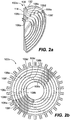
- a fluid manifold 100 includes a manifold body 102 and a plurality of annular passages 104a-f defined within the manifold body 102.
- the annular passages 104a-104f are concentric about a manifold axis A.
- Annular passages 104b-104f after the inner most annular passage 104a are nested radially outward from one another.
- the manifold body 102 includes a first manifold portion 102a and a second manifold portion 102b.
- the first and second manifold portions 102a and 102b, respectively, can be two separate pieces and can be brazed, welded or otherwise secured together.
- the first and second manifold portions 102a and 102b, respectively, can be formed as a single monolithic object by casting or additively manufacturing the manifold body 102.
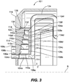
- Each of the passages 104a-104f are separated from one another with a respective cylindrical dividing portion 110a-110e, labeled in Fig. 3 .
- the annular passages 104a-104f are fluidically isolated from another by the cylindrical dividing portions 110a-110e.
- each annular passage 104a-104f includes a respective passage inlet 106a-106f and a plurality of respective passage outlets 108a-f downstream from their respective passage inlets 106a.
- the annular passage 104a as a single inlet 106a with multiple outlets 108a.
- the inlets 106a-106f of the annular passages 104a-104f are formed in an upstream axial facing surface 114 of the manifold body 102.
- the passage outlets 108a-f are all positioned at the same axial position relative to the manifold axis A. It is contemplated that some passage outlets can be positioned at different axial positions from one another.
- passage outlets 108a, 108c, and 108e can be associated with a gas fuel feed and can be at the same axial position
- passage outlets 108b, 108d and 108f can be associated with a liquid fuel feed and can be at the same axial position as one another, but a position different from that of outlets 108a, 108c and 108d.
- the passage outlets 108a-f are circumferentially offset from one another relative to the manifold axis A. It is also contemplated that some passage outlets can be positioned at the same circumferential positions relative to one another.
- passage outlets 108a and 108b can be associated with the first stage fuel distributor and can be at the same circumferential position, while passage outlets 108c and 108d can be associated with the second stage fuel distributor and can be at different circumferential position from passages 108a and 108b.
- each annular passage 104a-104f includes five respective passage outlets 108a-f.
- annular passage 104a includes five passage outlets 108a. While each annular passage is shown with five respective passage outlets, it is contemplated that in some embodiments more or less than five passage outlets can be used.
- Each annular passage 104a-104f is in fluid communication with a respective set of outlet channels 112a-f through its respective set of passage outlets 108a-f. The outlet channels 112a-f, branch off from their associated annular passage 104a-104f and extend in a radial direction relative to the manifold axis A.
- the manifold 100 including manifold body 102 is in a combustor system 101.
- the system 101 includes a combustor case 116 defining a manifold receptacle bore 118 therethrough.
- the manifold body 102 is seated in the manifold receptacle bore 118 to plug seal pressure within the combustor case 116.
- the system 101 includes a plurality of fuel distributors 120a-c. Each fuel distributor 120a-c is in fluid communication with two of annular passages 104a-f to facilitate three stage, dual fuel injection. Fuel distributors 120a-c are in communication with the inside of a combustor 103.
- the system 101 includes an ignitor 122 seated in a central passage of the manifold body 102 for ignition of fuel issued from the fuel distributors 120a-120c. While the embodiments herein show manifolds that facilitate three stage, dual fuel injection, it is contemplated that some embodiments can also be used for single fuel-type injection, and/or injection with any number of stages, such as two-stage injection.
- the system 101 includes sets of transfer tubes 124a-c downstream from the annular passages 104a-f.
- Each passage outlet 108a-f and its associated outlet channel 112a-f is associated with a respective one of the transfer tubes 124a-124c to fluidly connect the passage outlets 108a (and in turn their associated annular passage 104a) to various stages of the fuel distributors 120a-c.
- the number of transfer tubes can vary depending on the number of passage outlets 108 associated with a given annular passage 104.
- annular passages 104a and 104b are in fluid communication with first stage fuel distributor 120a through the first stage transfer tubes 124a.
- Five of the transfer tubes 124a fluidly connect annular passage 104a with first stage fuel distributor 120a, via the outlets 108a and outlet channels 112a of annular passage 104a.
- the other five transfer tubes 124a fluidly connect annular passage 104b with first stage fuel distributor 120a via the outlets 108b and outlet channels 112b of annular passage 104b. This allows system 101 to provide gas fuel to fuel distributor 120a through annular passage 104a and/or liquid fuel to fuel distributor 120a through annular passage 104b.
- annular passages 104c and 104d are in fluid communication with second stage fuel distributor 120b through transfer tubes 124b (10 total). Five of the transfer tubes 124b fluidly connect annular passage 104c with second stage fuel distributor 120b via the outlets 108c and outlet channels 112c of annular passage 104c. The other five transfer tubes 124b fluidly connect annular passage 104d with second stage fuel distributor 120b via the outlets 108d and outlet channels 112d of annular passage 104d. This allows system 101 to provide gas fuel to fuel distributor 120b through annular passage 104c and/or liquid fuel to fuel distributor 120b through annular passage 104d.
- Annular passages 104e and 104f are in fluid communication with third stage fuel distributor 120c through transfer tubes 124c.
- Five of the transfer tubes 124c fluidly connect annular passage 104e with third stage fuel distributor 120c via the outlets 108e and outlet channels 112e of annular passage 104e.
- the other five transfer tubes 124c fluidly connect annular passage 104f with third stage fuel distributor 120c via the outlets 108f and outlet channels 112f of annular passage 104f.
- This allows system 101 to provide gas fuel to fuel distributor 120c through annular passage 104e and/or liquid fuel to fuel distributor 120c through annular passage 104f. While it is described herein that each annular passage is associated with a given fuel distributor with five transfer tubes, it will be appreciated that in other embodiments the number of transfer tubes can vary depending on the number of outlets associated with a given annular passage.
- the manifold body 102 defines a seal groove 128 on an outer surface of the manifold body 102.
- the seal groove 128 includes an upstream facing seal surface 132 and a radially outward facing seal surface 134.
- the system 101 includes seal ring 126 between the manifold body 102 and the combustor case 116 that rests in the seal groove 128.
- the seal ring 126 abuts a downstream facing seal surface 130 on the combustor case 116, an upstream facing seal surface 132 of the seal groove 128 and a radially outward facing seal surface 134 of the seal groove 128.
- the seal ring 126 can be a c-seal ring.
- pressure from inside the combustor 103 pushes the manifold upstream, e.g. to the left as oriented in Fig. 4 , which tightens the seal.
- This arrangement requires a smaller seal surface as compared with traditional assemblies where the nozzle portions of combustors are removable from the outside of the combustor case and therefore must withstand the force from the pressure within the combustor.
- manifolds 100 and combustor systems 101 as described herein can be retrofitted into existing gas turbine engines.
- manifolds 100 as disclosed herein can be used in any suitable application where it is desired to maintain separate fluid circuits in a manifold, such as in food or chemical processing or the like.
- Manifolds as described herein allow for receiving fluids from multiple sources, and for delivering to multiple outlets for each source. It is contemplated that manifolds as described have multiple annular passages acting to divide fluid evenly among multiple individual circuits, e.g., for fuel injection. Manifolds as described herein can operate better at lower flow rates or power levels than traditional manifold arrangements. Manifolds as described herein can minimize manifold size for efficient packaging or advantageous envelope for multiple fluid circuits. Manifolds as described herein can fit within envelopes designed for traditional manifold arrangements, e.g., without taking up room outside a combustor case.
Landscapes
- Engineering & Computer Science (AREA)
- Chemical & Material Sciences (AREA)
- Combustion & Propulsion (AREA)
- Mechanical Engineering (AREA)
- General Engineering & Computer Science (AREA)
- Quick-Acting Or Multi-Walled Pipe Joints (AREA)
- Feeding And Controlling Fuel (AREA)
Claims (15)
- System, umfassend einen Treibstoffverteiler (100), wobei der Treibstoffverteiler (100) Folgendes umfasst:einen Verteilerkörper (102), wobei der Verteilerkörper (102) Folgendes umfasst:einen ersten ringförmigen Durchgang (104a), welcher in dem Verteilerkörper (102) zwischen einem ersten Durchgangseinlass (106a) und einem ersten Durchgangauslass (108a) stromabwärts von dem ersten Durchgangeinlass (106a) angeordnet ist; undein zweiter ringförmiger Durchgang (104b), welcher in dem Verteilerkörper (102) definiert ist, welcher radial nach außen von dem ersten ringförmigen Durchgang (104a) eingenistet ist, und zwischen einem zweiten Durchgangeinlass (106b) und einem zweiten Durchgangsauslass (108b) stromabwärts von dem zweiten Durchgangseinlass (106b), wobei der erste und zweite ringförmige Durchgang (104a, 104b) konzentrisch um eine Verteilerachse (A) sind, wobei der erste Durchgangsauslass (108a) und der zweite Durchgangsauslass (108b) in der gleichen axialen Position bezogen auf die Verteilerachse (A) positioniert sind,wobei das System ferner einen Treibstoffzuteiler (120a) umfasst,dadurch gekennzeichnet, dass der Verteilerkörper (102) ferner Folgendes umfasst:einen ersten Auslasskanal, welcher sich radial von dem ersten ringförmigen Durchgang erstreckt;einen zweiten Auslasskanal, welcher sich radial von dem ersten ringförmigen Durchgang erstreckt;ein erstes Übertragungsrohr (124a) stromabwärts von dem ersten Auslasskanal des Verteilerkörpers; undein zweites Übertragungsrohr (124b) stromabwärts von dem zweiten Auslasskanal des Verteilerkörpers, wobei der Treibstoffzuteiler (120a) über das erste und zweite Übertragungsrohr und den ersten und zweiten Auslasskanal in Fluidkommunikation mit dem ersten und zweiten ringförmigen Durchgang (104a, 104b) steht, wobei jeder des ersten und zweiten ringförmigen Durchgangsauslasses in Fluidkommunikation mit dem entsprechenden ersten und zweiten Auslasskanal steht, wobei der erste und zweite Auslasskanal bezogen auf die Verteilerachse (A) in der gleichen axialen Position positioniert sind.
- System nach Anspruch 1, wobei der erste Durchgangsauslass (108a) und der zweite Durchgangsauslass (108b) bezogen auf die Verteilerachse (A) umlaufend voneinander versetzt sind.
- System nach Anspruch 1 oder 2, ferner umfassend mindestens einen zusätzlichen ringförmigen Durchgang (104c, 104d, 104e, 104f), welcher in dem Verteilerkörper (102) definiert ist, wobei ein erster des mindestens einen zusätzlichen ringförmigen Durchgangs (104c, 104d, 104e, 104f) radial nach außen von dem zweiten ringförmigen Durchgang (104b) eingenistet ist.
- System nach Anspruch 1, 2 oder 3, wobei der Verteilerkörper (102) einen zylindrischen Trennteil (110a) beinhaltet, wobei der erste ringförmige Durchgang (104a) und der zweite ringförmige Durchgang (104b) durch den zylindrischen Trennteil (110a) fluidisch voneinander isoliert sind.
- System nach einem der vorstehenden Ansprüche, wobei der erste Durchgangsauslass (108a) einer von einer Vielzahl von unterschiedlichen ersten Durchgangsauslässen ist und wobei der entsprechende sich radial erstreckende Auslasskanal (112a) einer von einer Vielzahl von sich radial erstreckenden Auslasskanälen ist, wobei jeder der ersten Durchgangsauslässe (108a) mit einem entsprechenden der Vielzahl von sich radial erstreckenden Auslasskanälen (112a) in Fluidkommunikation steht, welche von dem ersten ringförmigen Durchgang (104a) abzweigen.
- System nach einem der vorstehenden Ansprüche, wobei der zweite Durchgangsauslass (108b) einer von einer Vielzahl von unterschiedlichen zweiten Durchgangsauslässen ist und wobei der entsprechende sich radial erstreckende Auslasskanal (112b) einer von einer Vielzahl von sich radial erstreckenden Auslasskanälen ist, wobei jeder der zweiten Durchgangsauslässe (108a) mit einem der Vielzahl von sich radial erstreckenden Auslasskanälen in Fluidkommunikation steht, welche von dem zweiten ringförmigen Durchgang (104b) abzweigen.
- System nach Anspruch 5 oder 6, wobei sich jeder der sich radial erstreckenden Auslasskanäle (112a, 112b) bezogen auf die Verteilerachse (A) in einer radialen Richtung erstreckt.
- System nach einem der vorstehenden Ansprüche, wobei die Einlässe des ersten und zweiten ringförmigen Durchgangs (104a, 104b) in einer stromaufwärtigen in axialer Richtung zeigende Fläche (114) des Verteilerkörpers (102) gebildet sind.
- System nach einem der vorstehenden Ansprüche, wobei der Verteilerkörper (102) eine Dichtungsnut (128) an einer äußeren Fläche des Verteilerkörpers (102) definiert.
- System nach Anspruch 9, wobei die Dichtungsnut (128) eine stromaufwärts zeigende Dichtungsfläche (132) und eine radial nach außen zeigende Dichtungsfläche (134) beinhaltet.
- System nach einem der vorstehenden Ansprüche, wobei der Verteilerkörper (102), welcher den ersten und zweiten ringförmigen Durchgang (104a, 104b) beinhaltet, ein einzelnes monolithisches Objekt ist, oder
wobei der Verteilerkörper (102) einen ersten Verteilerteil (102a) und einen zweiten Verteilerteil (102b) beinhaltet, wobei der erste und zweite Verteilerteil (102a, 102b) zusammengefügt sind, um den ersten und zweiten ringförmigen Durchgang (104a, 104b) zu bilden. - System nach Anspruch 1 und ferner umfassend:ein Brennkammergehäuse (116), welches eine Verteileraufnahmebohrung (118) dort hindurch definiert,wobei der Verteilerkörper (102) in der Verteileraufnahmebohrung (118) sitzt, um Dichtungsdruck in dem Brennkammergehäuse (116) zu verstopfen.
- System nach Anspruch 12, wobei der Verteiler zwei zusätzliche ringförmige Durchgänge zusätzlich zu dem erste ringförmigen Durchgang (104a) und dem zweiten ringförmigen Durchgang (104b) beinhaltet, und wobei beide der zwei zusätzlichen ringförmigen Durchgänge zur zweistufigen doppelten Treibstoffeinspritzung in Fluidkommunikation mit einem zweiten Treibstoffzuteiler (120b) stehen, oder
wobei der Verteiler zwei zusätzliche Paare von ringförmigen Durchgängen zusätzlich zu dem ersten ringförmigen Durchgang (104a) und dem zweiten ringförmigen Durchgang (104b) beinhaltet, und wobei jedes der zwei Paare von zusätzlichen Durchgängen zur dreistufigen doppelten Treibstoffeinspritzung in Fluidkommunikation mit einem entsprechenden zusätzlichen Treibstoffzuteiler (120b, 120c) steht. - System nach Anspruch 12 oder 13, ferner umfassend einen Zünder (122), welcher in einem mittleren Durchgang des Verteilerkörpers (102) sitzt, um Treibstoff zu entzünden, welcher von dem Treibstoffzuteiler (120a) ausgegeben wird.
- System nach Anspruch 12, 13 oder 14, ferner umfassend einen Dichtungsring (126) zwischen dem Verteilerkörper (102) und dem Brennkammergehäuse (116), wobei der Verteilerkörper (102) eine Dichtungsnut (128) an einer äußeren Fläche des Verteilerkörpers (102) definiert, wobei der Dichtungsring (126) in der Dichtungsnut (128) liegt, optional wobei der Dichtungsring (126) an eine stromabwärts zeigende Dichtungsfläche (130) auf dem Brennkammergehäuse (116), an eine stromaufwärtszeigende Dichtungsfläche (132) der Dichtungsnut (128) und an eine radial nach außen zeigende Dichtungsfläche (134) der Dichtungsnut (128) angrenzt.
Applications Claiming Priority (1)
| Application Number | Priority Date | Filing Date | Title |
|---|---|---|---|
| US15/714,265 US10570826B2 (en) | 2017-09-25 | 2017-09-25 | Fuel manifold with nested annular passages and radially extending channels |
Publications (2)
| Publication Number | Publication Date |
|---|---|
| EP3460217A1 EP3460217A1 (de) | 2019-03-27 |
| EP3460217B1 true EP3460217B1 (de) | 2021-10-27 |
Family
ID=63713614
Family Applications (1)
| Application Number | Title | Priority Date | Filing Date |
|---|---|---|---|
| EP18196247.3A Active EP3460217B1 (de) | 2017-09-25 | 2018-09-24 | Verteiler mit mehreren flüssigkeitskreisläufen |
Country Status (2)
| Country | Link |
|---|---|
| US (1) | US10570826B2 (de) |
| EP (1) | EP3460217B1 (de) |
Families Citing this family (1)
| Publication number | Priority date | Publication date | Assignee | Title |
|---|---|---|---|---|
| WO2026096352A1 (en) * | 2024-10-28 | 2026-05-07 | Borgwarner Inc. | Combustor head flange assembly for combustor and associated combustor system |
Family Cites Families (8)
| Publication number | Priority date | Publication date | Assignee | Title |
|---|---|---|---|---|
| US5361586A (en) * | 1993-04-15 | 1994-11-08 | Westinghouse Electric Corporation | Gas turbine ultra low NOx combustor |
| US6092363A (en) * | 1998-06-19 | 2000-07-25 | Siemens Westinghouse Power Corporation | Low Nox combustor having dual fuel injection system |
| GB9813972D0 (en) * | 1998-06-30 | 1998-08-26 | Rolls Royce Plc | A combustion chamber |
| US7134287B2 (en) * | 2003-07-10 | 2006-11-14 | General Electric Company | Turbine combustor endcover assembly |
| ITTO20050441A1 (it) | 2005-06-23 | 2006-12-24 | Ansaldo Energia Spa | Sistema di alimentazione perfezionato di bruciatori di turbine a gas utilizzante collettori anulari e tubazioni di prefissata flessibilita'. |
| US8205452B2 (en) * | 2009-02-02 | 2012-06-26 | General Electric Company | Apparatus for fuel injection in a turbine engine |
| WO2014133406A1 (en) | 2013-02-28 | 2014-09-04 | General Electric Company | System and method for a turbine combustor |
| US10774748B2 (en) | 2017-01-17 | 2020-09-15 | Delavan Inc. | Internal fuel manifolds |
-
2017
- 2017-09-25 US US15/714,265 patent/US10570826B2/en active Active
-
2018
- 2018-09-24 EP EP18196247.3A patent/EP3460217B1/de active Active
Non-Patent Citations (1)
| Title |
|---|
| None * |
Also Published As
| Publication number | Publication date |
|---|---|
| US10570826B2 (en) | 2020-02-25 |
| US20190093560A1 (en) | 2019-03-28 |
| EP3460217A1 (de) | 2019-03-27 |
Similar Documents
| Publication | Publication Date | Title |
|---|---|---|
| US10024238B2 (en) | Cooling system with a bearing compartment bypass | |
| EP2329121B1 (de) | Mehrkanalige brennstoffsammelleitung und konstruktionsverfahren | |
| EP2902605B1 (de) | Brennstoffverteilerleitung und Kraftstoffeinspritzanordnung für eine Gasturbine | |
| EP3643969B1 (de) | Mehrpunkteinspritzungssystem für eine gasturbinenbrennkammer | |
| CN107849937B (zh) | 涡轮中间框架辐条冷却系统及方法 | |
| EP2216596B1 (de) | Brennstoffdüse | |
| EP2182195B1 (de) | Gasturbinenbrennkammer | |
| US6711898B2 (en) | Fuel manifold block and ring with macrolaminate layers | |
| EP3336434B1 (de) | Zweikraftstoffradialstromdüse für eine gasturbine | |
| CA2494950A1 (en) | Nested channel ducts for nozzle construction and the like | |
| CA2520160A1 (en) | Jacketed pipe flange and method | |
| US11713717B2 (en) | Sectional fuel manifolds | |
| US11585275B2 (en) | Internal manifold for multipoint injection | |
| CN106481454A (zh) | 带有管段的燃气涡轮发动机冷却空气歧管 | |
| EP3894750B1 (de) | Kraftstoffinjektor mit lochplatte | |
| EP3460217A1 (de) | Mehrere schaltungsverteiler | |
| CN105579779A (zh) | 用于涡轮引擎的燃料喷射器 | |
| EP3450724B1 (de) | Integrierte sauerstoffentfernungseinheit und kraftstofffilter | |
| US10815805B2 (en) | Apparatus for supplying cooling air to a turbine | |
| CN114144633A (zh) | 管束热交换器 | |
| EP3348813B1 (de) | Interne kraftstoffverteiler und herstellungsverfahren | |
| US20200095935A1 (en) | Fuel manifold assembly | |
| WO2016001301A1 (en) | Fuel distribution device, gas turbine engine and mounting method | |
| US12338932B2 (en) | Pipe branching device and compressor | |
| EP3460218B1 (de) | Transferleitungen |
Legal Events
| Date | Code | Title | Description |
|---|---|---|---|
| PUAI | Public reference made under article 153(3) epc to a published international application that has entered the european phase |
Free format text: ORIGINAL CODE: 0009012 |
|
| STAA | Information on the status of an ep patent application or granted ep patent |
Free format text: STATUS: THE APPLICATION HAS BEEN PUBLISHED |
|
| AK | Designated contracting states |
Kind code of ref document: A1 Designated state(s): AL AT BE BG CH CY CZ DE DK EE ES FI FR GB GR HR HU IE IS IT LI LT LU LV MC MK MT NL NO PL PT RO RS SE SI SK SM TR |
|
| AX | Request for extension of the european patent |
Extension state: BA ME |
|
| STAA | Information on the status of an ep patent application or granted ep patent |
Free format text: STATUS: REQUEST FOR EXAMINATION WAS MADE |
|
| 17P | Request for examination filed |
Effective date: 20190926 |
|
| RBV | Designated contracting states (corrected) |
Designated state(s): AL AT BE BG CH CY CZ DE DK EE ES FI FR GB GR HR HU IE IS IT LI LT LU LV MC MK MT NL NO PL PT RO RS SE SI SK SM TR |
|
| STAA | Information on the status of an ep patent application or granted ep patent |
Free format text: STATUS: EXAMINATION IS IN PROGRESS |
|
| 17Q | First examination report despatched |
Effective date: 20201002 |
|
| GRAP | Despatch of communication of intention to grant a patent |
Free format text: ORIGINAL CODE: EPIDOSNIGR1 |
|
| STAA | Information on the status of an ep patent application or granted ep patent |
Free format text: STATUS: GRANT OF PATENT IS INTENDED |
|
| INTG | Intention to grant announced |
Effective date: 20210511 |
|
| GRAS | Grant fee paid |
Free format text: ORIGINAL CODE: EPIDOSNIGR3 |
|
| GRAA | (expected) grant |
Free format text: ORIGINAL CODE: 0009210 |
|
| STAA | Information on the status of an ep patent application or granted ep patent |
Free format text: STATUS: THE PATENT HAS BEEN GRANTED |
|
| AK | Designated contracting states |
Kind code of ref document: B1 Designated state(s): AL AT BE BG CH CY CZ DE DK EE ES FI FR GB GR HR HU IE IS IT LI LT LU LV MC MK MT NL NO PL PT RO RS SE SI SK SM TR |
|
| REG | Reference to a national code |
Ref country code: GB Ref legal event code: FG4D |
|
| REG | Reference to a national code |
Ref country code: CH Ref legal event code: EP |
|
| REG | Reference to a national code |
Ref country code: AT Ref legal event code: REF Ref document number: 1442001 Country of ref document: AT Kind code of ref document: T Effective date: 20211115 |
|
| REG | Reference to a national code |
Ref country code: DE Ref legal event code: R096 Ref document number: 602018025607 Country of ref document: DE |
|
| REG | Reference to a national code |
Ref country code: IE Ref legal event code: FG4D |
|
| REG | Reference to a national code |
Ref country code: LT Ref legal event code: MG9D |
|
| REG | Reference to a national code |
Ref country code: NL Ref legal event code: MP Effective date: 20211027 |
|
| REG | Reference to a national code |
Ref country code: AT Ref legal event code: MK05 Ref document number: 1442001 Country of ref document: AT Kind code of ref document: T Effective date: 20211027 |
|
| PG25 | Lapsed in a contracting state [announced via postgrant information from national office to epo] |
Ref country code: RS Free format text: LAPSE BECAUSE OF FAILURE TO SUBMIT A TRANSLATION OF THE DESCRIPTION OR TO PAY THE FEE WITHIN THE PRESCRIBED TIME-LIMIT Effective date: 20211027 Ref country code: LT Free format text: LAPSE BECAUSE OF FAILURE TO SUBMIT A TRANSLATION OF THE DESCRIPTION OR TO PAY THE FEE WITHIN THE PRESCRIBED TIME-LIMIT Effective date: 20211027 Ref country code: FI Free format text: LAPSE BECAUSE OF FAILURE TO SUBMIT A TRANSLATION OF THE DESCRIPTION OR TO PAY THE FEE WITHIN THE PRESCRIBED TIME-LIMIT Effective date: 20211027 Ref country code: BG Free format text: LAPSE BECAUSE OF FAILURE TO SUBMIT A TRANSLATION OF THE DESCRIPTION OR TO PAY THE FEE WITHIN THE PRESCRIBED TIME-LIMIT Effective date: 20220127 Ref country code: AT Free format text: LAPSE BECAUSE OF FAILURE TO SUBMIT A TRANSLATION OF THE DESCRIPTION OR TO PAY THE FEE WITHIN THE PRESCRIBED TIME-LIMIT Effective date: 20211027 |
|
| RAP4 | Party data changed (patent owner data changed or rights of a patent transferred) |
Owner name: COLLINS ENGINE NOZZLES, INC. |
|
| PG25 | Lapsed in a contracting state [announced via postgrant information from national office to epo] |
Ref country code: IS Free format text: LAPSE BECAUSE OF FAILURE TO SUBMIT A TRANSLATION OF THE DESCRIPTION OR TO PAY THE FEE WITHIN THE PRESCRIBED TIME-LIMIT Effective date: 20220227 Ref country code: SE Free format text: LAPSE BECAUSE OF FAILURE TO SUBMIT A TRANSLATION OF THE DESCRIPTION OR TO PAY THE FEE WITHIN THE PRESCRIBED TIME-LIMIT Effective date: 20211027 Ref country code: PT Free format text: LAPSE BECAUSE OF FAILURE TO SUBMIT A TRANSLATION OF THE DESCRIPTION OR TO PAY THE FEE WITHIN THE PRESCRIBED TIME-LIMIT Effective date: 20220228 Ref country code: PL Free format text: LAPSE BECAUSE OF FAILURE TO SUBMIT A TRANSLATION OF THE DESCRIPTION OR TO PAY THE FEE WITHIN THE PRESCRIBED TIME-LIMIT Effective date: 20211027 Ref country code: NO Free format text: LAPSE BECAUSE OF FAILURE TO SUBMIT A TRANSLATION OF THE DESCRIPTION OR TO PAY THE FEE WITHIN THE PRESCRIBED TIME-LIMIT Effective date: 20220127 Ref country code: NL Free format text: LAPSE BECAUSE OF FAILURE TO SUBMIT A TRANSLATION OF THE DESCRIPTION OR TO PAY THE FEE WITHIN THE PRESCRIBED TIME-LIMIT Effective date: 20211027 Ref country code: LV Free format text: LAPSE BECAUSE OF FAILURE TO SUBMIT A TRANSLATION OF THE DESCRIPTION OR TO PAY THE FEE WITHIN THE PRESCRIBED TIME-LIMIT Effective date: 20211027 Ref country code: HR Free format text: LAPSE BECAUSE OF FAILURE TO SUBMIT A TRANSLATION OF THE DESCRIPTION OR TO PAY THE FEE WITHIN THE PRESCRIBED TIME-LIMIT Effective date: 20211027 Ref country code: GR Free format text: LAPSE BECAUSE OF FAILURE TO SUBMIT A TRANSLATION OF THE DESCRIPTION OR TO PAY THE FEE WITHIN THE PRESCRIBED TIME-LIMIT Effective date: 20220128 Ref country code: ES Free format text: LAPSE BECAUSE OF FAILURE TO SUBMIT A TRANSLATION OF THE DESCRIPTION OR TO PAY THE FEE WITHIN THE PRESCRIBED TIME-LIMIT Effective date: 20211027 |
|
| REG | Reference to a national code |
Ref country code: DE Ref legal event code: R097 Ref document number: 602018025607 Country of ref document: DE |
|
| PG25 | Lapsed in a contracting state [announced via postgrant information from national office to epo] |
Ref country code: SM Free format text: LAPSE BECAUSE OF FAILURE TO SUBMIT A TRANSLATION OF THE DESCRIPTION OR TO PAY THE FEE WITHIN THE PRESCRIBED TIME-LIMIT Effective date: 20211027 Ref country code: SK Free format text: LAPSE BECAUSE OF FAILURE TO SUBMIT A TRANSLATION OF THE DESCRIPTION OR TO PAY THE FEE WITHIN THE PRESCRIBED TIME-LIMIT Effective date: 20211027 Ref country code: RO Free format text: LAPSE BECAUSE OF FAILURE TO SUBMIT A TRANSLATION OF THE DESCRIPTION OR TO PAY THE FEE WITHIN THE PRESCRIBED TIME-LIMIT Effective date: 20211027 Ref country code: EE Free format text: LAPSE BECAUSE OF FAILURE TO SUBMIT A TRANSLATION OF THE DESCRIPTION OR TO PAY THE FEE WITHIN THE PRESCRIBED TIME-LIMIT Effective date: 20211027 Ref country code: DK Free format text: LAPSE BECAUSE OF FAILURE TO SUBMIT A TRANSLATION OF THE DESCRIPTION OR TO PAY THE FEE WITHIN THE PRESCRIBED TIME-LIMIT Effective date: 20211027 Ref country code: CZ Free format text: LAPSE BECAUSE OF FAILURE TO SUBMIT A TRANSLATION OF THE DESCRIPTION OR TO PAY THE FEE WITHIN THE PRESCRIBED TIME-LIMIT Effective date: 20211027 |
|
| PLBE | No opposition filed within time limit |
Free format text: ORIGINAL CODE: 0009261 |
|
| STAA | Information on the status of an ep patent application or granted ep patent |
Free format text: STATUS: NO OPPOSITION FILED WITHIN TIME LIMIT |
|
| 26N | No opposition filed |
Effective date: 20220728 |
|
| PG25 | Lapsed in a contracting state [announced via postgrant information from national office to epo] |
Ref country code: AL Free format text: LAPSE BECAUSE OF FAILURE TO SUBMIT A TRANSLATION OF THE DESCRIPTION OR TO PAY THE FEE WITHIN THE PRESCRIBED TIME-LIMIT Effective date: 20211027 |
|
| PG25 | Lapsed in a contracting state [announced via postgrant information from national office to epo] |
Ref country code: SI Free format text: LAPSE BECAUSE OF FAILURE TO SUBMIT A TRANSLATION OF THE DESCRIPTION OR TO PAY THE FEE WITHIN THE PRESCRIBED TIME-LIMIT Effective date: 20211027 |
|
| PG25 | Lapsed in a contracting state [announced via postgrant information from national office to epo] |
Ref country code: MC Free format text: LAPSE BECAUSE OF FAILURE TO SUBMIT A TRANSLATION OF THE DESCRIPTION OR TO PAY THE FEE WITHIN THE PRESCRIBED TIME-LIMIT Effective date: 20211027 |
|
| REG | Reference to a national code |
Ref country code: CH Ref legal event code: PL |
|
| REG | Reference to a national code |
Ref country code: BE Ref legal event code: MM Effective date: 20220930 |
|
| PG25 | Lapsed in a contracting state [announced via postgrant information from national office to epo] |
Ref country code: IT Free format text: LAPSE BECAUSE OF FAILURE TO SUBMIT A TRANSLATION OF THE DESCRIPTION OR TO PAY THE FEE WITHIN THE PRESCRIBED TIME-LIMIT Effective date: 20211027 |
|
| PG25 | Lapsed in a contracting state [announced via postgrant information from national office to epo] |
Ref country code: LU Free format text: LAPSE BECAUSE OF NON-PAYMENT OF DUE FEES Effective date: 20220924 |
|
| P01 | Opt-out of the competence of the unified patent court (upc) registered |
Effective date: 20230530 |
|
| PG25 | Lapsed in a contracting state [announced via postgrant information from national office to epo] |
Ref country code: LI Free format text: LAPSE BECAUSE OF NON-PAYMENT OF DUE FEES Effective date: 20220930 Ref country code: IE Free format text: LAPSE BECAUSE OF NON-PAYMENT OF DUE FEES Effective date: 20220924 Ref country code: CH Free format text: LAPSE BECAUSE OF NON-PAYMENT OF DUE FEES Effective date: 20220930 |
|
| PG25 | Lapsed in a contracting state [announced via postgrant information from national office to epo] |
Ref country code: BE Free format text: LAPSE BECAUSE OF NON-PAYMENT OF DUE FEES Effective date: 20220930 |
|
| PG25 | Lapsed in a contracting state [announced via postgrant information from national office to epo] |
Ref country code: HU Free format text: LAPSE BECAUSE OF FAILURE TO SUBMIT A TRANSLATION OF THE DESCRIPTION OR TO PAY THE FEE WITHIN THE PRESCRIBED TIME-LIMIT; INVALID AB INITIO Effective date: 20180924 |
|
| PG25 | Lapsed in a contracting state [announced via postgrant information from national office to epo] |
Ref country code: CY Free format text: LAPSE BECAUSE OF FAILURE TO SUBMIT A TRANSLATION OF THE DESCRIPTION OR TO PAY THE FEE WITHIN THE PRESCRIBED TIME-LIMIT Effective date: 20211027 |
|
| PG25 | Lapsed in a contracting state [announced via postgrant information from national office to epo] |
Ref country code: MK Free format text: LAPSE BECAUSE OF FAILURE TO SUBMIT A TRANSLATION OF THE DESCRIPTION OR TO PAY THE FEE WITHIN THE PRESCRIBED TIME-LIMIT Effective date: 20211027 |
|
| PG25 | Lapsed in a contracting state [announced via postgrant information from national office to epo] |
Ref country code: MT Free format text: LAPSE BECAUSE OF FAILURE TO SUBMIT A TRANSLATION OF THE DESCRIPTION OR TO PAY THE FEE WITHIN THE PRESCRIBED TIME-LIMIT Effective date: 20211027 |
|
| PGFP | Annual fee paid to national office [announced via postgrant information from national office to epo] |
Ref country code: DE Payment date: 20250820 Year of fee payment: 8 |
|
| PGFP | Annual fee paid to national office [announced via postgrant information from national office to epo] |
Ref country code: GB Payment date: 20250822 Year of fee payment: 8 |
|
| PGFP | Annual fee paid to national office [announced via postgrant information from national office to epo] |
Ref country code: FR Payment date: 20250820 Year of fee payment: 8 |
|
| PG25 | Lapsed in a contracting state [announced via postgrant information from national office to epo] |
Ref country code: TR Free format text: LAPSE BECAUSE OF FAILURE TO SUBMIT A TRANSLATION OF THE DESCRIPTION OR TO PAY THE FEE WITHIN THE PRESCRIBED TIME-LIMIT Effective date: 20211027 |