EP3460187A1 - Schaufel für eine strömungsmaschine - Google Patents
Schaufel für eine strömungsmaschine Download PDFInfo
- Publication number
- EP3460187A1 EP3460187A1 EP18193086.8A EP18193086A EP3460187A1 EP 3460187 A1 EP3460187 A1 EP 3460187A1 EP 18193086 A EP18193086 A EP 18193086A EP 3460187 A1 EP3460187 A1 EP 3460187A1
- Authority
- EP
- European Patent Office
- Prior art keywords
- blade
- thickening
- region
- airfoil
- thickness
- Prior art date
- Legal status (The legal status is an assumption and is not a legal conclusion. Google has not performed a legal analysis and makes no representation as to the accuracy of the status listed.)
- Granted
Links
Images


Classifications
-
- F—MECHANICAL ENGINEERING; LIGHTING; HEATING; WEAPONS; BLASTING
- F01—MACHINES OR ENGINES IN GENERAL; ENGINE PLANTS IN GENERAL; STEAM ENGINES
- F01D—NON-POSITIVE DISPLACEMENT MACHINES OR ENGINES, e.g. STEAM TURBINES
- F01D5/00—Blades; Blade-carrying members; Heating, heat-insulating, cooling or antivibration means on the blades or the members
- F01D5/12—Blades
- F01D5/14—Form or construction
- F01D5/141—Shape, i.e. outer, aerodynamic form
-
- F—MECHANICAL ENGINEERING; LIGHTING; HEATING; WEAPONS; BLASTING
- F01—MACHINES OR ENGINES IN GENERAL; ENGINE PLANTS IN GENERAL; STEAM ENGINES
- F01D—NON-POSITIVE DISPLACEMENT MACHINES OR ENGINES, e.g. STEAM TURBINES
- F01D5/00—Blades; Blade-carrying members; Heating, heat-insulating, cooling or antivibration means on the blades or the members
- F01D5/12—Blades
- F01D5/14—Form or construction
- F01D5/147—Construction, i.e. structural features, e.g. of weight-saving hollow blades
-
- F—MECHANICAL ENGINEERING; LIGHTING; HEATING; WEAPONS; BLASTING
- F01—MACHINES OR ENGINES IN GENERAL; ENGINE PLANTS IN GENERAL; STEAM ENGINES
- F01D—NON-POSITIVE DISPLACEMENT MACHINES OR ENGINES, e.g. STEAM TURBINES
- F01D5/00—Blades; Blade-carrying members; Heating, heat-insulating, cooling or antivibration means on the blades or the members
- F01D5/12—Blades
- F01D5/22—Blade-to-blade connections, e.g. for damping vibrations
- F01D5/225—Blade-to-blade connections, e.g. for damping vibrations by shrouding
-
- F—MECHANICAL ENGINEERING; LIGHTING; HEATING; WEAPONS; BLASTING
- F05—INDEXING SCHEMES RELATING TO ENGINES OR PUMPS IN VARIOUS SUBCLASSES OF CLASSES F01-F04
- F05D—INDEXING SCHEME FOR ASPECTS RELATING TO NON-POSITIVE-DISPLACEMENT MACHINES OR ENGINES, GAS-TURBINES OR JET-PROPULSION PLANTS
- F05D2240/00—Components
- F05D2240/10—Stators
- F05D2240/12—Fluid guiding means, e.g. vanes
- F05D2240/123—Fluid guiding means, e.g. vanes related to the pressure side of a stator vane
-
- F—MECHANICAL ENGINEERING; LIGHTING; HEATING; WEAPONS; BLASTING
- F05—INDEXING SCHEMES RELATING TO ENGINES OR PUMPS IN VARIOUS SUBCLASSES OF CLASSES F01-F04
- F05D—INDEXING SCHEME FOR ASPECTS RELATING TO NON-POSITIVE-DISPLACEMENT MACHINES OR ENGINES, GAS-TURBINES OR JET-PROPULSION PLANTS
- F05D2240/00—Components
- F05D2240/20—Rotors
- F05D2240/30—Characteristics of rotor blades, i.e. of any element transforming dynamic fluid energy to or from rotational energy and being attached to a rotor
- F05D2240/301—Cross-sectional characteristics
-
- F—MECHANICAL ENGINEERING; LIGHTING; HEATING; WEAPONS; BLASTING
- F05—INDEXING SCHEMES RELATING TO ENGINES OR PUMPS IN VARIOUS SUBCLASSES OF CLASSES F01-F04
- F05D—INDEXING SCHEME FOR ASPECTS RELATING TO NON-POSITIVE-DISPLACEMENT MACHINES OR ENGINES, GAS-TURBINES OR JET-PROPULSION PLANTS
- F05D2240/00—Components
- F05D2240/20—Rotors
- F05D2240/30—Characteristics of rotor blades, i.e. of any element transforming dynamic fluid energy to or from rotational energy and being attached to a rotor
- F05D2240/305—Characteristics of rotor blades, i.e. of any element transforming dynamic fluid energy to or from rotational energy and being attached to a rotor related to the pressure side of a rotor blade
-
- F—MECHANICAL ENGINEERING; LIGHTING; HEATING; WEAPONS; BLASTING
- F05—INDEXING SCHEMES RELATING TO ENGINES OR PUMPS IN VARIOUS SUBCLASSES OF CLASSES F01-F04
- F05D—INDEXING SCHEME FOR ASPECTS RELATING TO NON-POSITIVE-DISPLACEMENT MACHINES OR ENGINES, GAS-TURBINES OR JET-PROPULSION PLANTS
- F05D2250/00—Geometry
- F05D2250/10—Two-dimensional
- F05D2250/12—Two-dimensional rectangular
-
- F—MECHANICAL ENGINEERING; LIGHTING; HEATING; WEAPONS; BLASTING
- F05—INDEXING SCHEMES RELATING TO ENGINES OR PUMPS IN VARIOUS SUBCLASSES OF CLASSES F01-F04
- F05D—INDEXING SCHEME FOR ASPECTS RELATING TO NON-POSITIVE-DISPLACEMENT MACHINES OR ENGINES, GAS-TURBINES OR JET-PROPULSION PLANTS
- F05D2260/00—Function
- F05D2260/94—Functionality given by mechanical stress related aspects such as low cycle fatigue [LCF] of high cycle fatigue [HCF]
- F05D2260/941—Functionality given by mechanical stress related aspects such as low cycle fatigue [LCF] of high cycle fatigue [HCF] particularly aimed at mechanical or thermal stress reduction
-
- Y—GENERAL TAGGING OF NEW TECHNOLOGICAL DEVELOPMENTS; GENERAL TAGGING OF CROSS-SECTIONAL TECHNOLOGIES SPANNING OVER SEVERAL SECTIONS OF THE IPC; TECHNICAL SUBJECTS COVERED BY FORMER USPC CROSS-REFERENCE ART COLLECTIONS [XRACs] AND DIGESTS
- Y02—TECHNOLOGIES OR APPLICATIONS FOR MITIGATION OR ADAPTATION AGAINST CLIMATE CHANGE
- Y02T—CLIMATE CHANGE MITIGATION TECHNOLOGIES RELATED TO TRANSPORTATION
- Y02T50/00—Aeronautics or air transport
- Y02T50/60—Efficient propulsion technologies, e.g. for aircraft
Definitions
- the invention relates to a blade for a turbomachine, in particular for a gas turbine.
- the invention further relates to a turbomachine, a compressor and a turbine with a stator and / or rotor blading.
- Object of the present invention is to provide a blade for a turbomachine, which has an aerodynamically favorable blade profile with high mechanical stability. Further objects of the invention are to provide a turbomachine, a compressor and a turbine, which each have an aerodynamically favorable stator and / or rotor blading with simultaneously high mechanical stability.
- a first aspect of the invention relates to a blade for a turbomachine, wherein the blade comprises an airfoil with at least one thickening on a pressure side of the airfoil.
- the blade comprises an airfoil with at least one thickening on a pressure side of the airfoil.
- an aerodynamically favorable blade profile at the same time high mechanical stability ensured by the fact that the thickening has a region of constant thickness.
- the thickening is not concave in contrast to the prior art, but at least partially has a constant thickness or thickness.
- the local thickening thus follows, at least in this area of constant thickness, more or less in the manner of a stamp (patch) of the contour of the (imaginary) thinnessless blade profile.
- the remaining regions of the airfoil can have an aerodynamically optimized and comparatively thinner airfoil profile.
- the local thickening of the airfoil reduces the static load on the airfoil. Due to the lower static load of the blade creates a higher reserve for the combination with vibration loads.
- the thickening is an integral part of the airfoil or urgeformt together with the airfoil. This can be done by an appropriate adaptation of possibly existing casting tools.
- the thickening together with the airfoil can be made additive and / or produced by a separation process.
- the thickening can be subsequently produced, for example, by build-up welding or other coating methods, whereby even existing blades can be equipped with the advantageous thickening.
- "one" within the scope of this disclosure are to be read as indefinite articles, that is to say always without expressly stated otherwise as "at least one / at least one”. Conversely, "one” can also be understood as "only one”.
- the area of constant thickness has a surface which corresponds to at least 20% of a total area of the thickening.
- the surface of the constant thickness region will have a proportion or at least a content of 20%, 21%, 22%, 23%, 24%, 25%, 26%, 27%, 28%, 29 %, 30%, 31%, 32%, 33%, 34%, 35%, 36%, 37%, 38%, 39%, 40%, 41%, 42%, 43%, 44%, 45%, 46%, 47%, 48%, 49%, 50%, 51%, 52%, 53%, 54%, 55%, 56%, 57%, 58%, 59%, 60%, 61%, 62% 63% 64% 65% 66% 67% 68% 69% 70% 71% 72% 73% 74% 75% 76% 77% 78% 79 %, 80%, 81%, 82%, 83%, 84%, 85%, 86%, 87%, 88%, 89%,
- a maximum length of the region with constant thickness corresponds to at least 1% and / or at most 90% of a maximum total length of the thickening.
- its maximum length may therefore be, for example, 1%, 2%, 3%, 4%, 5%, 6%, 7%, 8%, 9%, 10%, 11%, 12%.
- the thickening is at least substantially rectangular, the maximum total length corresponds at least substantially to the diagonal, for example if the thickening is essentially circular, the maximum total length corresponds to the diameter.
- the maximum total length of the thickening as well as the maximum length of the area of constant thickness must be determined individually.
- the term “length” and “width” generally refer to an "axial extent”, while the term “height” refers to a "radial extent” in the installed state of the blade.
- the thickening may in particular be formed with a ratio of greater to smaller rectangular side length of ⁇ 10: 1, preferably ⁇ 5: 1, in particular ⁇ 2: 1.
- a particularly high mechanical stability is achieved in a further embodiment of the invention in that the thickening and / or the region of constant thickness is or are at least substantially rectangular.
- at least substantially rectangular geometry are meant both strictly rectangular or square geometries and corresponding geometries with one or more rounded corners.
- the thickening is formed at a distance from a leading edge and / or from a trailing edge of the blade.
- the thickening does not directly adjoin the leading edge and / or trailing edge of the airfoil, but at a minimum distance relative to a chordwise tangent of the airfoil is arranged. This avoids unnecessary damage to the aerodynamic properties of the blade.
- a minimum distance from the chordal longitudinal tangent of the airfoil may be provided which corresponds at least to the edge radius of the leading edge and / or trailing edge. Since the leading and / or trailing edge itself is not changed, the aerodynamic influence of the thickening is particularly low.
- the thickness of the region of constant thickness at least 0.1 mm or at least 4% of a maximum profile thickness, that is, for example, or at least 0.1 mm, 0.2 mm, 0.3 mm , 0.4 mm, 0.5 mm, 0.6 mm, 0.7 mm, 0.8 mm, 0.9 mm, 1.0 mm, 1.1 mm, 1.2 mm, 1.3 mm , 1.4 mm, 1.5 mm, 1.6 mm, 1.7 mm, 1.8 mm, 1.9 mm, 2.0 mm, 2.1 mm, 2.2 mm, 2.3 mm , 2.4 mm, 2.5 mm, 2.6 mm, 2.7 mm, 2.8 mm, 2.9 mm, 3.0 mm, 3.1 mm, 3.2 mm, 3.3 mm , 3.4mm, 3.5mm, 3.6mm, 3.7mm, 3.8mm, 3.9mm, 4.0mm, 4.1mm, 4.2mm, 4.3mm, 0.5 mm, 0.6 mm, 0.7
- the thickening extends from a radially outer end region or end of the blade over a maximum of 20% and / or a minimum of 5% of a channel height.
- the thickening is formed at a radially outer end portion of the airfoil. It may have a height or radial extent inward, for example, or at least 20%, 19%, 18%, 17%, 16%, 15%, 14%, 13%, 12%, 11%, 10%, 9 %, 8%, 7%, 6%, 5%, 4%, 3%, 2%, 1% or less corresponds to a channel height associated with the bucket.
- the channel height can generally correspond to the blade height (radial length), wherein the blade is usually slightly larger than the channel height, at least at the inlet, in order to safely capture the operating medium of the turbomachine and to better take into account inaccuracies and thermal expansions.
- the thickening comprises at least one edge region whose Thickness decreases continuously from the region of constant thickness continuously to a normal profile thickness of the airfoil without thickening.
- the edge region surrounds the region of constant thickness in a U-shape.
- an axial extent, in particular maximum axial extent, of the thickening being a maximum of 70% and / or a minimum of 10% of a chord length of the blade at the level of the thickening.
- extensions of 70%, 69%, 68%, 67%, 66%, 65%, 64%, 63%, 62%, 61%, 60%, 59 are at an extent of up to 70% of the chordal length of the airfoil %, 58%, 57%, 56%, 55%, 54%, 53%, 52%, 51%, 50%, 49%, 48%, 47%, 46%, 45%, 44%, 43%, 42%, 41%, 40%, 39%, 38%, 37%, 36%, 35%, 34%, 33%, 32%, 31%, 30%, 29%, 28%, 27%, 26% , 25%, 24%, 23%, 22%, 21%, 20%, 19%, 18%, 17%, 16%, 15%, 14%, 13%, 12%, 11%, 10% or less
- the blade is designed as a particular adjustable vane or as a blade, the advantages of the invention can be implemented particularly flexible for different blade types and stages of a turbomachine.
- the airfoil is bounded by a radially outer shroud and / or by a radially inner shroud.
- the blade can additionally be stabilized against vibrations and a flow path of the operating medium of the associated turbomachine can be axially sealed.
- two or more blades may optionally be interconnected by a common shroud as a blade cluster.
- a second aspect of the invention relates to a turbomachine, in particular a gas turbine, with a stator and / or rotor blading, which is aerodynamically favorable according to the invention and at the same time has a high mechanical stability, by the stator and / or rotor blading at least one blade according to the first aspect of the invention includes. Further features and the resulting advantages can be found in the descriptions of the first aspect of the invention.
- a third aspect of the invention relates to a compressor of a turbomachine, in particular a low-pressure or high-pressure compressor, with a stator and / or rotor blading, which aerodynamically favorable according to the invention and at the same time has a high mechanical stability by the stator and / or rotor blading at least one Shovel according to the first aspect of the invention comprises. Further features and the resulting advantages can be found in the descriptions of the first aspect of the invention.
- a fourth aspect of the invention relates to a turbine of a turbomachine, in particular a low-pressure or high-pressure turbine, with a stator and / or rotor blading, which is aerodynamically favorable according to the invention and at the same time has a high mechanical stability, by the stator and / or rotor blading at least one Shovel according to the first aspect of the invention comprises. Further features and the resulting advantages can be found in the descriptions of the first aspect of the invention.
- Fig. 1 shows a perspective view of an embodiment of a blade 10 according to the invention for a turbomachine, for example for an aircraft engine.
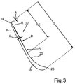
- Fig. 1 is described below in synopsis with Fig. 2 and Fig. 3 explains Fig. 2 a side view of in Fig. 1 shown blade 10 and Fig. 3 a sectional view of the blade 10 in the region of a thickening 22 shows.
- the blade 10 comprises a blade root 12, a radially inner shroud 14, an airfoil 16 and a radially outer shroud 18.
- On a pressure side 20 of the blade 16 there is a thickening 22 in the area marked by the reference character I, which is also referred to as "Patch" can be called.
- the thickening 22 is stamp-like on the pressure side 20 in the radially outer region of the airfoil 16 is placed toward a trailing edge 24 and in the present case has a substantially rectangular shape with two rounded corners.
- the thickening 22 has a region B of constant thickness D, which is surrounded in a U-shape by an edge region R, the thickness D of the edge region R starting from the region B of constant thickness D continuously up to a normal profile thickness of the airfoil 16 without thickening 22 decreases.
- the transition into the original aerodynamic profile takes place continuously starting from the region B of constant thickness D, so that the airfoil 16 outside the thickening 22 again has an aerodynamically optimized blade profile P.
- the thickening 22 Upward or radially outward, the thickening 22 has no edge region R, but adjoins the radially outer shroud 18.
- the thickening 22 is arranged at a distance A from the trailing edge 24.
- the distance A corresponds approximately to a radius HKR of the trailing edge 24.
- the trailing edge 24 itself is therefore not changed by the thickening 22.
- the maximum total length or axial extent AE In the present case, the thickening 22 is about 2/3 of the chord length S of the blade 16 at the level of the thickening 22, so that a leading edge 26 of the blade 16 remains unchanged.
- the region B of constant thickness D extends in the axial direction over about 2/3 of the total length of the thickening 22, so that the edge region R extends over about 1/3 of the total length of the thickening 22.
- the maximum radial extent RE or height of the thickening 22 in the present case is about 15% or less of a channel height H, measured from the outer shroud 18.
- the channel height H will, as in Fig. 2 shown, in the region of the trailing edge 24 determined and corresponds to the radial extent or height of the airfoil 16 between the radial shrouds 14, 18, optionally plus a tolerance.
- the area B of the thickening 22, that is, the area with a constant distance to the original blade profile P, has a thickness D, which in the present case may be selected between 0.1 mm and a value which corresponds to the radius HKR of the trailing edge 24.
Landscapes
- Engineering & Computer Science (AREA)
- Mechanical Engineering (AREA)
- General Engineering & Computer Science (AREA)
- Physics & Mathematics (AREA)
- Fluid Mechanics (AREA)
- Architecture (AREA)
- Structures Of Non-Positive Displacement Pumps (AREA)
Abstract
Description
- Die Erfindung betrifft eine Schaufel für eine Strömungsmaschine, insbesondere für eine Gasturbine. Die Erfindung betrifft weiterhin eine Strömungsmaschine, einen Verdichter sowie eine Turbine mit einer Stator- und/oder Rotorbeschaufelung.
- Bei modernen Strömungsmaschinen, beispielsweise bei Flugturbinen, sind insbesondere die Schaufeln stromabliegender Stufen sehr hoch statisch ausgelastet. Hinzu kommt eine dynamische Anregung durch unterschiedlichste Erregungen bestimmter Ordnungen. Diese Kombination kann im schlimmsten Fall zu einer Beschädigung der Schaufeln führen. Daher ist es bekannt, Schaufeln ausgehend von einem aerodynamisch optimalen Schaufelprofil lokal aufzudicken, um die statischen und/oder dynamischen Belastungen mit möglichst geringer aerodynamischer Beeinträchtigung zu reduzieren. Beispielsweise ist es aus der
WO 2011/015193 A2 bekannt, eine Druckseite des Schaufelblatts einer Schaufel mit einer konvexen Aufdickung zu versehen. - Aufgabe der vorliegenden Erfindung ist es, eine Schaufel für eine Strömungsmaschine bereitzustellen, welche ein aerodynamisch günstiges Schaufelprofil bei gleichzeitig hoher mechanischer Stabilität aufweist. Weitere Aufgaben der Erfindung bestehen darin, eine Strömungsmaschine, einen Verdichter und eine Turbine bereitzustellen, welche jeweils eine aerodynamisch günstige Stator- und/oder Rotorbeschaufelung mit gleichzeitig hoher mechanischer Stabilität aufweisen.
- Die Aufgaben werden erfindungsgemäß durch eine Schaufel mit den Merkmalen des Patentanspruchs 1, durch eine Strömungsmaschine gemäß Patentanspruch 13, einen Verdichter gemäß Patentanspruch 14 sowie durch eine Turbine gemäß Patentanspruch 15 gelöst. Vorteilhafte Ausgestaltungen mit zweckmäßigen Weiterbildungen der Erfindung sind in den Unteransprüchen angegeben, wobei vorteilhafte Ausgestaltungen jedes Erfindungsaspekts als vorteilhafte Ausgestaltungen der jeweils anderen Erfindungsaspekte anzusehen sind.
- Ein erster Aspekt der Erfindung betrifft eine Schaufel für eine Strömungsmaschine, wobei die Schaufel ein Schaufelblatt mit mindestens einer Aufdickung auf einer Druckseite des Schaufelblatts umfasst. Erfindungsgemäß wird ein aerodynamisch günstiges Schaufelprofil bei gleichzeitig hoher mechanischer Stabilität dadurch sichergestellt, dass die Aufdickung einen Bereich mit konstanter Dicke aufweist. Mit anderen Worten ist es vorgesehen, dass die Aufdickung im Unterschied zum Stand der Technik nicht konkav geformt ist, sondern zumindest bereichsweise eine konstante Dicke oder Stärke aufweist. Die lokale Aufdickung folgt damit zumindest in diesem Bereich konstanter Dicke quasi in der Art einer Briefmarke (Patch) der Kontur des (gedachten) aufdickungslosen Schaufelprofils. Die restlichen Bereiche des Schaufelblatts können demgegenüber ein aerodynamisch optimiertes und vergleichsweise dünneres Schaufelblattprofil aufweisen. Durch die lokale Aufdickung des Schaufelblatts wird die statische Belastung der Schaufel reduziert. Durch die geringere statische Belastung der Schaufel entsteht eine höhere Reserve für die Kombination mit Schwingbelastungen. Vorzugsweise ist die Aufdickung integraler Teil des Schaufelblatts bzw. gemeinsam mit dem Schaufelblatt urgeformt. Dies kann durch eine entsprechende Anpassung von gegebenenfalls bereits vorhandenen Gußwerkzeugen erfolgen. Alternativ kann die Aufdickung zusammen mit dem Schaufelblatt additiv hergestellt und/oder durch ein Trennverfahren erzeugt werden. Alternativ kann die Aufdickung beispielsweise durch Auftragsschweißen oder andere Beschichtungsverfahren nachträglich hergestellt werden, wodurch auch bereits vorhandene Schaufeln mit der vorteilhaften Aufdickung ausgestattet werden können. Generell sind "ein/eine" im Rahmen dieser Offenbarung als unbestimmte Artikel zu lesen, also ohne ausdrücklich gegenteilige Angabe immer auch als "mindestens ein/mindestens eine". Umgekehrt können "ein/eine" auch als "nur ein/nur eine" verstanden werden.
- In einer vorteilhaften Ausgestaltung der Erfindung ist vorgesehen, dass der Bereich mit konstanter Dicke eine Oberfläche aufweist, welche mindestens 20 % einer Gesamtfläche der Aufdickung entspricht. Mit anderen Worten ist es vorgesehen, dass die Oberfläche des Bereichs mit konstanter Dicke einen Anteil oder mindestens einen Anteil von 20 %, 21 %, 22 %, 23 %, 24 %, 25 %, 26 %, 27 %, 28 %, 29 %, 30 %, 31 %, 32 %, 33 %, 34 %, 35 %, 36 %, 37 %, 38 %, 39 %, 40 %, 41 %, 42 %, 43 %, 44 %, 45 %, 46 %, 47 %, 48 %, 49 %, 50 %, 51 %, 52 %, 53 %, 54 %, 55 %, 56 %, 57 %, 58 %, 59 %, 60 %, 61 %, 62 %, 63 %, 64 %, 65 %, 66 %, 67 %, 68 %, 69 %, 70 %, 71 %, 72 %, 73 %, 74 %, 75 %, 76 %, 77 %, 78 %, 79 %, 80 %, 81 %, 82 %, 83 %, 84 %, 85 %, 86 %, 87 %, 88 %, 89 %, 90 %, 91 %, 92 %, 93 %, 94 %, 95 %, 96 %, 97 %, 98 %, 99 % oder 100 % an der Gesamtoberfläche der Aufdickung besitzt. Hierdurch kann die mechanische Stabilität optimal unter Berücksichtigung der jeweiligen aerodynamischen Eigenschaften eingestellt werden.
- In einer weiteren vorteilhaften Ausgestaltung der Erfindung ist vorgesehen, dass eine maximale Länge des Bereichs mit konstanter Dicke mindestens 1 % und/oder maximal 90 % einer maximalen Gesamtlänge der Aufdickung entspricht. In Abhängigkeit der Geometrie des Bereichs mit konstanter Dicke kann dessen maximale Länge also beispielsweise 1 %, 2 %, 3 %, 4 %, 5 %, 6 %, 7 %, 8 %, 9 %, 10 %, 11 %, 12 %, 13 %, 14 %, 15 %, 16 %, 17 %, 18 %, 19 %, 20 %, 21 %, 22 %, 23 %, 24 %, 25 %, 26 %, 27 %, 28 %, 29 %, 30 %, 31 %, 32 %, 33 %, 34 %, 35 %, 36 %, 37 %, 38 %, 39 %, 40 %, 41 %, 42 %, 43 %, 44 %, 45 %, 46 %, 47 %, 48 %, 49 %, 50 %, 51 %, 52 %, 53 %, 54 %, 55 %, 56 %, 57 %, 58 %, 59 %, 60 %, 61 %, 62 %, 63 %, 64 %, 65 %, 66 %, 67 %, 68 %, 69 %, 70 %, 71 %, 72 %, 73 %, 74 %, 75 %, 76 %, 77 %, 78 %, 79 %, 80 %, 81 %, 82 %, 83 %, 84 %, 85 %, 86 %, 87 %, 88 %, 89 %, 90 %, 91 %, 92 %, 93 %, 94 %, 95 %, 96 %, 97 %, 98 %, 99 % oder 100 % bzw. 90 %, 89 %, 88 %, 87 %, 86 %, 85 %, 84 %, 83 %, 82 %, 81 %, 80 % oder weniger der maximalen Gesamtlänge der Aufdickung entsprechen. Wenn die Aufdickung beispielsweise zumindest im Wesentlichen rechteckig ausgebildet ist, entspricht die maximale Gesamtlänge zumindest im Wesentlichen der Diagonalen, ist die Aufdickung beispielsweise im Wesentlichen kreisförmig, entspricht die maximale Gesamtlänge dem Durchmesser. Bei anderen Geometrien sind die maximale Gesamtlänge der Aufdickung sowie die maximale Länge des Bereichs konstanter Dicke entsprechend individuell zu bestimmen. Im Rahmen der vorliegenden Offenbarung beziehen sich die Begriff "Länge" bzw. "Breite" generell auf eine "axiale Erstreckung", während sich der Begriff "Höhe" auf eine "radiale Erstreckung" im eingebauten Zustand der Schaufel bezieht. Dabei kann die Aufdickung insbesondere mit einem Verhältnis von größerer zu kleinerer Rechteckseitenlänge von ≤ 10:1, vorzugsweise ≤ 5:1, insbesondere ≤ 2:1 ausgebildet sein.
- Eine besonders hohe mechanische Stabilität wird in weiterer Ausgestaltung der Erfindung dadurch erreicht, dass die Aufdickung und/oder der Bereich mit konstanter Dicke zumindest im Wesentlichen rechteckig ausgebildet ist bzw. sind. Unter einer "zumindest im Wesentlichen rechteckigen" Geometrie sind dabei sowohl streng rechteckige bzw. quadratische Geometrien sowie entsprechende Geometrien mit einer oder mehreren abgerundeten Ecken zu verstehen.
- Weitere Vorteile ergeben sich, indem die Aufdickung von einer Vorderkante und/oder von einer Hinterkante des Schaufelblatts beabstandet ausgebildet ist. Mit anderen Worten ist es vorgesehen, dass die Aufdickung nicht unmittelbar an die Vorderkante und/oder Hinterkante des Schaufelblatts anschließt, sondern in einem Mindestabstand bezogen auf eine Sehnenlängentangente des Schaufelblatts angeordnet ist. Hierdurch werden unnötige Beeinträchtigungen der aerodynamischen Eigenschaften der Schaufel vermieden. Beispielsweise kann ein Mindestabstand von der Sehnenlängentangente des Schaufelblatts vorgesehen sein, der zumindest dem Kantenradius der Vorderkante und/oder Hinterkante entspricht. Da die Vorder- und/oder Hinterkante selbst nicht geändert wird, ist der aerodynamische Einfluss der Aufdickung besonders gering.
- In einer weiteren vorteilhaften Ausgestaltung der Erfindung ist vorgesehen, dass die Dicke des Bereichs mit konstanter Dicke mindestens 0,1 mm oder mindestens 4% einer maximalen Profildicke, also beispielsweise oder auch mindestens 0,1 mm, 0,2 mm, 0,3 mm, 0,4 mm, 0,5 mm, 0,6 mm, 0,7 mm, 0,8 mm, 0,9 mm, 1,0 mm, 1,1 mm, 1,2 mm, 1,3 mm, 1,4 mm, 1,5 mm, 1,6 mm, 1,7 mm, 1,8 mm, 1,9 mm, 2,0 mm, 2,1 mm, 2,2 mm, 2,3 mm, 2,4 mm, 2,5 mm, 2,6 mm, 2,7 mm, 2,8 mm, 2,9 mm, 3,0 mm, 3,1 mm, 3,2 mm, 3,3 mm, 3,4 mm, 3,5 mm, 3,6 mm, 3,7 mm, 3,8 mm, 3,9 mm, 4,0 mm, 4,1 mm, 4,2 mm, 4,3 mm, 4,4 mm, 4,5 mm, 4,6 mm, 4,7 mm, 4,8 mm, 4,9 mm, 5,0 mm beträgt oder mehr beträgt und/oder maximal 1 mm, vorzugsweise 0,5 mm, oder maximal 16% einer maximalen Profildicke beträgt und/oder maximal einem Wert eines Radius der Vorderkante und/oder eines Radius der Hinterkante des Schaufelblatts entspricht. Die maximale Profildicke entspricht dabei dem Durchmesser des größtmöglichen Kreises, der vollständig in einen Profilquerschnitt einbeschrieben werden kann.
- In einer weiteren vorteilhaften Ausgestaltung der Erfindung ist vorgesehen, dass sich die Aufdickung ausgehend von einem radial außenliegenden Endbereich oder Ende des Schaufelblatts über maximal 20 % und/oder minimal 5% einer Kanalhöhe erstreckt. Mit anderen Worten ist die Aufdickung an einem radial äußeren Endbereich des Schaufelblatts ausgebildet. Sie kann eine Höhe bzw. radiale Erstreckung nach innen aufweisen, die beispielsweise oder mindestens 20 %, 19 %, 18 %, 17 %, 16 %, 15 %, 14 %, 13 %, 12 %, 11 %, 10 %, 9 %, 8 %, 7 %, 6 %, 5 %, 4 %, 3 %, 2 %, 1 % oder weniger einer der Schaufel zugeordneten Kanalhöhe entspricht. Die Kanalhöhe kann generell der Schaufelhöhe (radiale Länge) entsprechen, wobei die Schaufel zumindest am Eintritt üblicherweise etwas größer als die Kanalhöhe ist, um das Betriebsmedium der Strömungsmaschine sicher aufzufangen und Ungenauigkeiten und Wärmedehnungen besser zu berücksichtigen.
- Möglichst vorteilhafte aerodynamische Eigenschaften werden in weiterer Ausgestaltung der Erfindung dadurch erreicht, dass die Aufdickung wenigstens einen Randbereich umfasst, dessen Dicke ausgehend vom Bereich mit konstanter Dicke kontinuierlich bis zu einer normalen Profildicke des Schaufelblatts ohne Aufdickung abnimmt. Hierdurch kann die Anströmung der Aufdickung strömungsmechanisch besonders vorteilhaft und störungsarm erfolgen.
- In einer weiteren vorteilhaften Ausgestaltung der Erfindung ist vorgesehen, dass der Randbereich den Bereich mit konstanter Dicke U-förmig umgibt. Hierdurch kann eine strömungsmechanisch besonders günstige An- und Abströmung erreicht werden. Dies ist insbesondere dann von Vorteil, wenn die Aufdickung nach radial außen hin mit einem radialen Endbereich des Schaufelblatts abschließt.
- Weitere Vorteile ergeben sich, indem eine axiale Erstreckung, insbesondere maximale axiale Erstreckung, der Aufdickung maximal 70 % und/oder minimal 10% einer Sehnenlänge des Schaufelblatts auf Höhe der Aufdickung beträgt. Unter einer Erstreckung von maximal 70 % der Sehnenlänge des Schaufelblatts sind dabei insbesondere Erstreckungen von 70 %, 69 %, 68 %, 67 %, 66 %, 65 %, 64 %, 63 %, 62 %, 61 %, 60 %, 59 %, 58 %, 57 %, 56 %, 55 %, 54 %, 53 %, 52 %, 51 %, 50 %, 49 %, 48 %, 47 %, 46 %, 45 %, 44 %, 43 %, 42 %, 41 %, 40 %, 39 %, 38 %, 37 %, 36 %, 35 %, 34 %, 33 %, 32 %, 31 %, 30 %, 29 %, 28 %, 27 %, 26 %, 25 %, 24 %, 23 %, 22 %, 21 %, 20 %, 19 %, 18 %, 17 %, 16 %, 15 %, 14 %, 13 %, 12 %, 11 %, 10 % oder weniger zu verstehen. Die maximale axiale Erstreckung oder Breite kann beispielsweise 2/3 der Sehnenlänge des Schaufelblatts auf Höhe der Aufdickung oder weniger sein.
- Indem die Schaufel als insbesondere verstellbare Leitschaufel oder als Laufschaufel ausgebildet ist, können die erfindungsgemäßen Vorteile besonders flexibel für unterschiedliche Schaufeltypen und Stufen einer Strömungsmaschine realisiert werden.
- In einer weiteren vorteilhaften Ausgestaltung der Erfindung ist vorgesehen, dass das Schaufelblatt durch ein radial äußeres Deckband und/oder durch ein radial inneres Deckband begrenzt ist. Hierdurch kann die Schaufel zusätzlich gegen Schwingungen stabilisiert und ein Strömungspfad des Betriebsmediums der zugeordneten Strömungsmaschine axial abgedichtet werden. Darüber hinaus können zwei oder mehr Schaufeln gegebenenfalls durch ein gemeinsames Deckband als Schaufelcluster miteinander verbunden sein.
- Ein zweiter Aspekt der Erfindung betrifft eine Strömungsmaschine, insbesondere eine Gasturbine, mit einer Stator- und/oder Rotorbeschaufelung, welche erfindungsgemäß aerodynamisch günstig ist und gleichzeitig eine hohe mechanische Stabilität aufweist, indem die Stator- und/oder Rotorbeschaufelung mindestens eine Schaufel gemäß dem ersten Erfindungsaspekt umfasst. Weitere Merkmale und die sich hieraus ergebenden Vorteile sind den Beschreibungen des ersten Erfindungsaspekts zu entnehmen.
- Ein dritter Aspekt der Erfindung betrifft einen Verdichter einer Strömungsmaschine, insbesondere einen Niederdruck- oder Hochdruckverdichter, mit einer Stator- und/oder Rotorbeschaufelung, welche erfindungsgemäß aerodynamisch günstig ist und gleichzeitig eine hohe mechanische Stabilität aufweist, indem die Stator- und/oder Rotorbeschaufelung mindestens eine Schaufel gemäß dem ersten Erfindungsaspekt umfasst. Weitere Merkmale und die sich hieraus ergebenden Vorteile sind den Beschreibungen des ersten Erfindungsaspekts zu entnehmen.
- Ein vierter Aspekt der Erfindung betrifft eine Turbine einer Strömungsmaschine, insbesondere eine Niederdruck- oder Hochdruckturbine, mit einer Stator- und/oder Rotorbeschaufelung, welche erfindungsgemäß aerodynamisch günstig ist und gleichzeitig eine hohe mechanische Stabilität aufweist, indem die Stator- und/oder Rotorbeschaufelung mindestens eine Schaufel gemäß dem ersten Erfindungsaspekt umfasst. Weitere Merkmale und die sich hieraus ergebenden Vorteile sind den Beschreibungen des ersten Erfindungsaspekts zu entnehmen.
- Weitere Merkmale der Erfindung ergeben sich aus den Ansprüchen, den Figuren und der Figurenbeschreibung. Die vorstehend in der Beschreibung genannten Merkmale und Merkmalskombinationen, sowie die nachfolgend in der Figurenbeschreibung genannten und/oder in den Figuren alleine gezeigten Merkmale und Merkmalskombinationen sind nicht nur in der jeweils angegebenen Kombination, sondern auch in anderen Kombinationen verwendbar, ohne den Rahmen der Erfindung zu verlassen. Es sind somit auch Ausführungen von der Erfindung als umfasst und offenbart anzusehen, die in den Figuren nicht explizit gezeigt und erläutert sind, jedoch durch separierte Merkmalskombinationen aus den erläuterten Ausführungen hervorgehen und erzeugbar sind. Es sind auch Ausführungen und Merkmalskombinationen als offenbart anzusehen, die somit nicht alle Merkmale eines ursprünglich formulierten unabhängigen Anspruchs aufweisen. Es sind darüber hinaus Ausführungen und Merkmalskombinationen, insbesondere durch die oben dargelegten Ausführungen, als offenbart anzusehen, die über die in den Rückbezügen der Ansprüche dargelegten Merkmalskombinationen hinausgehen oder von diesen abweichen. Dabei zeigt:
- Fig. 1
- eine Perspektivansicht eines Ausführungsbeispiels einer erfindungsgemäßen Schaufel für eine Strömungsmaschine;
- Fig. 2
- eine Seitenansicht der in
Fig. 1 gezeigten Schaufel; und - Fig. 3
- eine Schnittansicht der Schaufel im Bereich einer Aufdickung.
-
Fig. 1 zeigt eine Perspektivansicht eines Ausführungsbeispiels einer erfindungsgemäßen Schaufel 10 für eine Strömungsmaschine, beispielsweise für ein Flugtriebwerk.Fig. 1 wird im Folgenden in Zusammenschau mitFig. 2 undFig. 3 erläutert, wobeiFig. 2 eine Seitenansicht der inFig. 1 gezeigten Schaufel 10 undFig. 3 eine Schnittansicht der Schaufel 10 im Bereich einer Aufdickung 22 zeigt. Die Schaufel 10 umfasst im gezeigten Ausführungsbeispiel einen Schaufelfuß 12, ein radial inneres Deckband 14, ein Schaufelblatt 16 sowie ein radial äußeres Deckband 18. An einer Druckseite 20 des Schaufelblatts 16 befindet sich im mit dem Bezugszeichen I markierten Bereich eine Aufdickung 22, die auch als "Patch" bezeichnet werden kann. Man erkennt, dass die Aufdickung 22 briefmarkenähnlich an der Druckseite 20 im radial äußeren Bereich des Schaufelblatt 16 zu einer Hinterkante 24 hin platziert ist und vorliegend eine im Wesentlichen rechteckige Form mit zwei abgerundeten Ecken besitzt. Die Aufdickung 22 weist einen Bereich B mit konstanter Dicke D auf, der U-förmig von einem Randbereich R umgeben ist, wobei die Dicke D des Randbereichs R ausgehend vom Bereich B mit konstanter Dicke D kontinuierlich bis zu einer normalen Profildicke des Schaufelblatts 16 ohne Aufdickung 22 abnimmt. Mit anderen Worten erfolgt der Übergang in das ursprüngliche aerodynamische Profil ausgehend vom Bereich B konstanter Dicke D kontinuierlich, so dass das Schaufelblatt 16 außerhalb der Aufdickung 22 wieder ein aerodynamisch optimiertes Schaufelprofil P aufweist. Nach oben bzw. radial außen hin weist die Aufdickung 22 keinen Randbereich R auf, sondern schließt an das radial äußere Deckband 18 an. - Die Aufdickung 22 ist in einem Abstand A von der Hinterkante 24 angeordnet. Der Abstand A entspricht etwa einem Radius HKR der Hinterkante 24. Die Hinterkante 24 selbst wird durch die Aufdickung 22 daher nicht verändert. Die maximale Gesamtlänge oder axiale Erstreckung AE der Aufdickung 22 beträgt vorliegend etwa 2/3 der Sehnenlänge S des Schaufelblatts 16 in Höhe der Aufdickung 22, so dass auch eine Vorderkante 26 des Schaufelblatts 16 unverändert bleibt. Der Bereich B mit konstanten Dicke D erstreckt sich in axialer Richtung vorliegend über etwa 2/3 der Gesamtlänge der Aufdickung 22, so dass der Randbereich R sich über etwa 1/3 der Gesamtlänge der Aufdickung 22 erstreckt.
- Die maximale radiale Erstreckung RE oder Höhe der Aufdickung 22 beträgt vorliegend etwa 15 % oder weniger einer Kanalhöhe H, gemessen vom äußeren Deckband 18 aus. Die Kanalhöhe H wird, wie in
Fig. 2 dargestellt, im Bereich der Hinterkante 24 ermittelt und entspricht der radialen Erstreckung oder Höhe des Schaufelblatts 16 zwischen den radialen Deckbändern 14, 18, gegebenenfalls zuzüglich einer Toleranz. Der Bereich B der Aufdickung 22, das heißt der Bereich mit konstantem Abstand zum ursprünglichen Schaufelprofil P, weist eine Dicke D auf, die vorliegend zwischen 0,1 mm und einem Wert gewählt sein kann, welcher dem Radius HKR der Hinterkante 24 entspricht. - Die in den Unterlagen angegebenen Parameterwerte zur Definition von Messbedingungen für die Charakterisierung von spezifischen Eigenschaften des Erfindungsgegenstands sind auch im Rahmen von Abweichungen - beispielsweise aufgrund von Messfehlern, Systemfehlern, DIN-Toleranzen und dergleichen - als vom Rahmen der Erfindung mitumfasst anzusehen.
-
- 10
- Schaufel
- 12
- Schaufelfuß
- 14
- Deckband
- 14
- Deckbändern
- 16
- Schaufelblatt
- 18
- Deckband
- 20
- Druckseite
- 22
- Aufdickung
- 24
- Hinterkante
- 26
- Vorderkante
- I
- Bereich
- B
- Bereich konstanter Dicke
- D
- Dicke
- R
- Randbereich
- P
- Schaufelblattprofil
- HKR
- Radius der Hinterkante 24
- S
- Sehenlänge
- H
- Kanalhöhe
- RE
- radiale Erstreckung
- AE
- axiale Erstreckung
Claims (15)
- Schaufel (10) für eine Strömungsmaschine, umfassend ein Schaufelblatt (16) mit mindestens einer Aufdickung (22) auf einer Druckseite (20) des Schaufelblatts (16),
dadurch gekennzeichnet, dass
die Aufdickung (22) einen Bereich (B) mit konstanter Dicke (D) aufweist. - Schaufel (10) nach Anspruch 1,
dadurch gekennzeichnet, dass
der Bereich (B) mit konstanter Dicke (D) eine Oberfläche aufweist, welche mindestens 20 % einer Gesamtfläche der Aufdickung (22) entspricht. - Schaufel (10) nach Anspruch 1 oder 2,
dadurch gekennzeichnet, dass
eine maximale Länge des Bereichs (B) mit konstanter Dicke (D) mindestens 1 % und/oder maximal 90 % einer maximalen Gesamtlänge (AE) der Aufdickung (22) entspricht. - Schaufel (10) nach einem der Ansprüche 1 bis 3,
dadurch gekennzeichnet, dass
die Aufdickung (22) und/oder der Bereich (B) mit konstanter Dicke (D) zumindest im Wesentlichen rechteckig ausgebildet ist, insbesondere mit einem Verhältnis von größerer zu kleinerer Rechteckseitenlänge von ≤ 10:1, vorzugsweise ≤ 5:1, insbesondere ≤ 2:1. - Schaufel (10) nach einem der Ansprüche 1 bis 4,
dadurch gekennzeichnet, dass
die Aufdickung (22) von einer Vorderkante (26) und/oder von einer Hinterkante (24) des Schaufelblatts (16) beabstandet ausgebildet ist. - Schaufel (10) nach einem der Ansprüche 1 bis 5,
dadurch gekennzeichnet, dass
die Dicke (D) des Bereichs (B) mit konstanter Dicke (D) mindestens 0,1 mm oder 4% einer maximalen Profildicke beträgt und/oder maximal 1 mm, vorzugsweise 0,5 mm, oder maximal 16% einer maximalen Profildicke beträgt und/oder maximal einem Wert eines Radius der Vorderkante (26) und/oder eines Radius (HKR) der Hinterkante (24) des Schaufelblatts (16) entspricht. - Schaufel (10) nach einem der Ansprüche 1 bis 6,
dadurch gekennzeichnet, dass
sich die Aufdickung (22) ausgehend von einem radial außenliegenden Endbereich oder Ende des Schaufelblatts (16) über maximal 20 % und/oder minimal 5% einer Kanalhöhe (H) erstreckt. - Schaufel (10) nach einem der Ansprüche 1 bis 7,
dadurch gekennzeichnet, dass
die Aufdickung (22) wenigstens einen Randbereich (R) umfasst, dessen Dicke (D) ausgehend vom Bereich (B) mit konstanter Dicke (D) kontinuierlich bis zu einer normalen Profildicke des Schaufelblatts (16) ohne Aufdickung (22) abnimmt. - Schaufel (10) nach Anspruch 8,
dadurch gekennzeichnet, dass
der Randbereich (R) den Bereich (B) mit konstanter Dicke (D) U-förmig umgibt. - Schaufel (10) nach einem der Ansprüche 1 bis 9,
dadurch gekennzeichnet, dass
eine axiale Erstreckung, insbesondere maximale axiale Erstreckung, der Aufdickung (22) maximal 70 % und/oder minimal 10% einer Sehnenlänge (S) des Schaufelblatts (16) auf Höhe der Aufdickung (22) beträgt. - Schaufel (10) nach einem der Ansprüche 1 bis 10,
dadurch gekennzeichnet, dass
diese als insbesondere verstellbare Leitschaufel oder als Laufschaufel ausgebildet ist. - Schaufel (10) nach einem der Ansprüche 1 bis 11,
dadurch gekennzeichnet, dass
das Schaufelblatt (16) durch ein radial äußeres Deckband (18) und/oder durch ein radial inneres Deckband (14) begrenzt ist. - Strömungsmaschine, insbesondere Gasturbine, mit einer Stator- und/oder Rotorbeschaufelung umfassend mindestens eine Schaufel (10) gemäß einem der Ansprüche 1 bis 12.
- Verdichter einer Strömungsmaschine, insbesondere Niederdruck- oder Hochdruckverdichter, mit einer Stator- und/oder Rotorbeschaufelung umfassend mindestens eine Schaufel (10) gemäß einem der Ansprüche 1 bis 12.
- Turbine einer Strömungsmaschine, insbesondere Niederdruck- oder Hochdruckturbine, mit einer Stator- und/oder Rotorbeschaufelung umfassend mindestens eine Schaufel (10) gemäß einem der Ansprüche 1 bis 12.
Applications Claiming Priority (1)
| Application Number | Priority Date | Filing Date | Title |
|---|---|---|---|
| DE102017216620.7A DE102017216620A1 (de) | 2017-09-20 | 2017-09-20 | Schaufel für eine Strömungsmaschine |
Publications (2)
| Publication Number | Publication Date |
|---|---|
| EP3460187A1 true EP3460187A1 (de) | 2019-03-27 |
| EP3460187B1 EP3460187B1 (de) | 2021-07-14 |
Family
ID=63528544
Family Applications (1)
| Application Number | Title | Priority Date | Filing Date |
|---|---|---|---|
| EP18193086.8A Active EP3460187B1 (de) | 2017-09-20 | 2018-09-07 | Schaufel für eine strömungsmaschine |
Country Status (4)
| Country | Link |
|---|---|
| US (1) | US10947850B2 (de) |
| EP (1) | EP3460187B1 (de) |
| DE (1) | DE102017216620A1 (de) |
| ES (1) | ES2881457T3 (de) |
Families Citing this family (3)
| Publication number | Priority date | Publication date | Assignee | Title |
|---|---|---|---|---|
| US11421702B2 (en) | 2019-08-21 | 2022-08-23 | Pratt & Whitney Canada Corp. | Impeller with chordwise vane thickness variation |
| FR3143676A1 (fr) * | 2022-12-16 | 2024-06-21 | Safran Aircraft Engines | système PROPULSIF AERONAUTIQUE |
| FR3143683A1 (fr) * | 2022-12-16 | 2024-06-21 | Safran Aircraft Engines | Systeme propulsif aeronautique |
Citations (4)
| Publication number | Priority date | Publication date | Assignee | Title |
|---|---|---|---|---|
| US20030118447A1 (en) * | 2001-11-16 | 2003-06-26 | Fiatavio S.P.A. | Bladed member, in particular for an axial turbine of an aircraft engine |
| EP1471209A2 (de) * | 2003-04-23 | 2004-10-27 | General Electric Company | Vorrichtung zur Verminderung von Schwingungen einer Gasturbinenschaufel |
| WO2011015193A2 (de) * | 2009-08-06 | 2011-02-10 | Mtu Aero Engines Gmbh | Schaufelblatt |
| US20150361808A1 (en) * | 2014-06-17 | 2015-12-17 | Snecma | Turbomachine vane including an antivortex fin |
Family Cites Families (6)
| Publication number | Priority date | Publication date | Assignee | Title |
|---|---|---|---|---|
| US4257741A (en) * | 1978-11-02 | 1981-03-24 | General Electric Company | Turbine engine blade with airfoil projection |
| DE19612394C2 (de) | 1996-03-28 | 1999-03-11 | Mtu Muenchen Gmbh | Schaufelblatt für Strömungsmaschinen |
| US6457938B1 (en) * | 2001-03-30 | 2002-10-01 | General Electric Company | Wide angle guide vane |
| GB2381298A (en) * | 2001-10-26 | 2003-04-30 | Rolls Royce Plc | A turbine blade having a greater thickness to chord ratio |
| US9506347B2 (en) * | 2012-12-19 | 2016-11-29 | Solar Turbines Incorporated | Compressor blade for gas turbine engine |
| US10895161B2 (en) * | 2016-10-28 | 2021-01-19 | Honeywell International Inc. | Gas turbine engine airfoils having multimodal thickness distributions |
-
2017
- 2017-09-20 DE DE102017216620.7A patent/DE102017216620A1/de not_active Withdrawn
-
2018
- 2018-09-07 ES ES18193086T patent/ES2881457T3/es active Active
- 2018-09-07 US US16/125,104 patent/US10947850B2/en active Active
- 2018-09-07 EP EP18193086.8A patent/EP3460187B1/de active Active
Patent Citations (4)
| Publication number | Priority date | Publication date | Assignee | Title |
|---|---|---|---|---|
| US20030118447A1 (en) * | 2001-11-16 | 2003-06-26 | Fiatavio S.P.A. | Bladed member, in particular for an axial turbine of an aircraft engine |
| EP1471209A2 (de) * | 2003-04-23 | 2004-10-27 | General Electric Company | Vorrichtung zur Verminderung von Schwingungen einer Gasturbinenschaufel |
| WO2011015193A2 (de) * | 2009-08-06 | 2011-02-10 | Mtu Aero Engines Gmbh | Schaufelblatt |
| US20150361808A1 (en) * | 2014-06-17 | 2015-12-17 | Snecma | Turbomachine vane including an antivortex fin |
Also Published As
| Publication number | Publication date |
|---|---|
| EP3460187B1 (de) | 2021-07-14 |
| US20190085700A1 (en) | 2019-03-21 |
| US10947850B2 (en) | 2021-03-16 |
| ES2881457T3 (es) | 2021-11-29 |
| DE102017216620A1 (de) | 2019-03-21 |
Similar Documents
| Publication | Publication Date | Title |
|---|---|---|
| DE602004006323T2 (de) | Verfahren zur Herstellung einer Turbine mit Turbinenschaufeln unterschiedlicher Resonanzfrequenzen samt einer solchen Turbine | |
| DE102017218886A1 (de) | Schaufel und Rotor für eine Strömungsmaschine sowie Strömungsmaschine | |
| EP2927503B1 (de) | Gasturbinenverdichter, Flugtriebwerk und Auslegungsverfahren | |
| EP3536974B1 (de) | Gasturbinenverdichter | |
| DE102009036406A1 (de) | Schaufelblatt | |
| DE102009025814A1 (de) | Unterschneidung an einer Verdichterrotorschaufel | |
| EP3460187B1 (de) | Schaufel für eine strömungsmaschine | |
| EP2811118B1 (de) | Leitschaufelsegment einer Strömungsmaschine und Turbine | |
| DE102015206384A1 (de) | Deckbandanordnung einer Schaufelreihe von Stator- oder Rotorschaufeln | |
| EP2394028B1 (de) | Abdichtvorrichtung an dem Schaufelschaft einer Rotorstufe einer axialen Strömungsmaschine und ihre Verwendung | |
| EP3401504B1 (de) | Schaufelgitter | |
| EP2787178B1 (de) | Leitschaufelanordnung | |
| EP2410131B1 (de) | Rotor einer Turbomaschine | |
| DE102016217093A1 (de) | Koppelbolzen sowie Turbine mit Koppelbolzen | |
| WO2005116404A1 (de) | Schaufelblatt mit übergangszone | |
| EP3358135B1 (de) | Konturierung einer schaufelgitterplattform | |
| DE967498C (de) | Laufschaufelbefestigung bei Axialstroemungsmaschinen | |
| EP3704386A1 (de) | Generativ gefertigter zwischenkanal zur anordnung zwischen einem niederdruckverdichter und einem hochdruckverdichter, sowie entsprechendes fertigungsverfahren | |
| EP2650475B1 (de) | Schaufel für eine Strömungsmaschine, Schaufelanordnung sowie Strömungsmaschine | |
| EP3717748B1 (de) | Laufschaufel einer strömungsmaschine und verfahren zum herstellen derselben | |
| WO2000057030A1 (de) | Turbomaschinenschaufel | |
| EP4400694A1 (de) | Blisk | |
| EP3623576B1 (de) | Gasturbinen-laufschaufel | |
| EP3404211A1 (de) | Schaufelgittersegment für eine turbine mit konturierter plattformoberfläche, zugehörige schaufelgitter, schaufelkanal, plattform, turbine und flugzeugtriebwerk | |
| DE102013220467A1 (de) | Rotor mit einem Rotorgrundkörper und einer Mehrzahl daran angebrachter Laufschaufeln |
Legal Events
| Date | Code | Title | Description |
|---|---|---|---|
| PUAI | Public reference made under article 153(3) epc to a published international application that has entered the european phase |
Free format text: ORIGINAL CODE: 0009012 |
|
| STAA | Information on the status of an ep patent application or granted ep patent |
Free format text: STATUS: THE APPLICATION HAS BEEN PUBLISHED |
|
| AK | Designated contracting states |
Kind code of ref document: A1 Designated state(s): AL AT BE BG CH CY CZ DE DK EE ES FI FR GB GR HR HU IE IS IT LI LT LU LV MC MK MT NL NO PL PT RO RS SE SI SK SM TR |
|
| AX | Request for extension of the european patent |
Extension state: BA ME |
|
| STAA | Information on the status of an ep patent application or granted ep patent |
Free format text: STATUS: REQUEST FOR EXAMINATION WAS MADE |
|
| 17P | Request for examination filed |
Effective date: 20190910 |
|
| RBV | Designated contracting states (corrected) |
Designated state(s): AL AT BE BG CH CY CZ DE DK EE ES FI FR GB GR HR HU IE IS IT LI LT LU LV MC MK MT NL NO PL PT RO RS SE SI SK SM TR |
|
| GRAP | Despatch of communication of intention to grant a patent |
Free format text: ORIGINAL CODE: EPIDOSNIGR1 |
|
| STAA | Information on the status of an ep patent application or granted ep patent |
Free format text: STATUS: GRANT OF PATENT IS INTENDED |
|
| GRAJ | Information related to disapproval of communication of intention to grant by the applicant or resumption of examination proceedings by the epo deleted |
Free format text: ORIGINAL CODE: EPIDOSDIGR1 |
|
| GRAP | Despatch of communication of intention to grant a patent |
Free format text: ORIGINAL CODE: EPIDOSNIGR1 |
|
| GRAJ | Information related to disapproval of communication of intention to grant by the applicant or resumption of examination proceedings by the epo deleted |
Free format text: ORIGINAL CODE: EPIDOSDIGR1 |
|
| INTG | Intention to grant announced |
Effective date: 20200507 |
|
| GRAP | Despatch of communication of intention to grant a patent |
Free format text: ORIGINAL CODE: EPIDOSNIGR1 |
|
| GRAJ | Information related to disapproval of communication of intention to grant by the applicant or resumption of examination proceedings by the epo deleted |
Free format text: ORIGINAL CODE: EPIDOSDIGR1 |
|
| GRAP | Despatch of communication of intention to grant a patent |
Free format text: ORIGINAL CODE: EPIDOSNIGR1 |
|
| STAA | Information on the status of an ep patent application or granted ep patent |
Free format text: STATUS: REQUEST FOR EXAMINATION WAS MADE |
|
| GRAJ | Information related to disapproval of communication of intention to grant by the applicant or resumption of examination proceedings by the epo deleted |
Free format text: ORIGINAL CODE: EPIDOSDIGR1 |
|
| STAA | Information on the status of an ep patent application or granted ep patent |
Free format text: STATUS: EXAMINATION IS IN PROGRESS |
|
| INTG | Intention to grant announced |
Effective date: 20200527 |
|
| INTG | Intention to grant announced |
Effective date: 20200612 |
|
| INTC | Intention to grant announced (deleted) | ||
| 17Q | First examination report despatched |
Effective date: 20200625 |
|
| GRAP | Despatch of communication of intention to grant a patent |
Free format text: ORIGINAL CODE: EPIDOSNIGR1 |
|
| STAA | Information on the status of an ep patent application or granted ep patent |
Free format text: STATUS: GRANT OF PATENT IS INTENDED |
|
| INTG | Intention to grant announced |
Effective date: 20210129 |
|
| GRAS | Grant fee paid |
Free format text: ORIGINAL CODE: EPIDOSNIGR3 |
|
| GRAA | (expected) grant |
Free format text: ORIGINAL CODE: 0009210 |
|
| STAA | Information on the status of an ep patent application or granted ep patent |
Free format text: STATUS: THE PATENT HAS BEEN GRANTED |
|
| AK | Designated contracting states |
Kind code of ref document: B1 Designated state(s): AL AT BE BG CH CY CZ DE DK EE ES FI FR GB GR HR HU IE IS IT LI LT LU LV MC MK MT NL NO PL PT RO RS SE SI SK SM TR |
|
| REG | Reference to a national code |
Ref country code: GB Ref legal event code: FG4D Free format text: NOT ENGLISH |
|
| REG | Reference to a national code |
Ref country code: IE Ref legal event code: FG4D Free format text: LANGUAGE OF EP DOCUMENT: GERMAN |
|
| REG | Reference to a national code |
Ref country code: DE Ref legal event code: R096 Ref document number: 502018006109 Country of ref document: DE |
|
| REG | Reference to a national code |
Ref country code: AT Ref legal event code: REF Ref document number: 1410805 Country of ref document: AT Kind code of ref document: T Effective date: 20210815 |
|
| REG | Reference to a national code |
Ref country code: LT Ref legal event code: MG9D |
|
| REG | Reference to a national code |
Ref country code: NL Ref legal event code: MP Effective date: 20210714 |
|
| REG | Reference to a national code |
Ref country code: ES Ref legal event code: FG2A Ref document number: 2881457 Country of ref document: ES Kind code of ref document: T3 Effective date: 20211129 |
|
| PG25 | Lapsed in a contracting state [announced via postgrant information from national office to epo] |
Ref country code: NL Free format text: LAPSE BECAUSE OF FAILURE TO SUBMIT A TRANSLATION OF THE DESCRIPTION OR TO PAY THE FEE WITHIN THE PRESCRIBED TIME-LIMIT Effective date: 20210714 Ref country code: PT Free format text: LAPSE BECAUSE OF FAILURE TO SUBMIT A TRANSLATION OF THE DESCRIPTION OR TO PAY THE FEE WITHIN THE PRESCRIBED TIME-LIMIT Effective date: 20211115 Ref country code: NO Free format text: LAPSE BECAUSE OF FAILURE TO SUBMIT A TRANSLATION OF THE DESCRIPTION OR TO PAY THE FEE WITHIN THE PRESCRIBED TIME-LIMIT Effective date: 20211014 Ref country code: LT Free format text: LAPSE BECAUSE OF FAILURE TO SUBMIT A TRANSLATION OF THE DESCRIPTION OR TO PAY THE FEE WITHIN THE PRESCRIBED TIME-LIMIT Effective date: 20210714 Ref country code: BG Free format text: LAPSE BECAUSE OF FAILURE TO SUBMIT A TRANSLATION OF THE DESCRIPTION OR TO PAY THE FEE WITHIN THE PRESCRIBED TIME-LIMIT Effective date: 20211014 Ref country code: HR Free format text: LAPSE BECAUSE OF FAILURE TO SUBMIT A TRANSLATION OF THE DESCRIPTION OR TO PAY THE FEE WITHIN THE PRESCRIBED TIME-LIMIT Effective date: 20210714 Ref country code: FI Free format text: LAPSE BECAUSE OF FAILURE TO SUBMIT A TRANSLATION OF THE DESCRIPTION OR TO PAY THE FEE WITHIN THE PRESCRIBED TIME-LIMIT Effective date: 20210714 Ref country code: RS Free format text: LAPSE BECAUSE OF FAILURE TO SUBMIT A TRANSLATION OF THE DESCRIPTION OR TO PAY THE FEE WITHIN THE PRESCRIBED TIME-LIMIT Effective date: 20210714 Ref country code: SE Free format text: LAPSE BECAUSE OF FAILURE TO SUBMIT A TRANSLATION OF THE DESCRIPTION OR TO PAY THE FEE WITHIN THE PRESCRIBED TIME-LIMIT Effective date: 20210714 |
|
| PG25 | Lapsed in a contracting state [announced via postgrant information from national office to epo] |
Ref country code: PL Free format text: LAPSE BECAUSE OF FAILURE TO SUBMIT A TRANSLATION OF THE DESCRIPTION OR TO PAY THE FEE WITHIN THE PRESCRIBED TIME-LIMIT Effective date: 20210714 Ref country code: LV Free format text: LAPSE BECAUSE OF FAILURE TO SUBMIT A TRANSLATION OF THE DESCRIPTION OR TO PAY THE FEE WITHIN THE PRESCRIBED TIME-LIMIT Effective date: 20210714 Ref country code: GR Free format text: LAPSE BECAUSE OF FAILURE TO SUBMIT A TRANSLATION OF THE DESCRIPTION OR TO PAY THE FEE WITHIN THE PRESCRIBED TIME-LIMIT Effective date: 20211015 |
|
| REG | Reference to a national code |
Ref country code: DE Ref legal event code: R097 Ref document number: 502018006109 Country of ref document: DE |
|
| PG25 | Lapsed in a contracting state [announced via postgrant information from national office to epo] |
Ref country code: DK Free format text: LAPSE BECAUSE OF FAILURE TO SUBMIT A TRANSLATION OF THE DESCRIPTION OR TO PAY THE FEE WITHIN THE PRESCRIBED TIME-LIMIT Effective date: 20210714 |
|
| REG | Reference to a national code |
Ref country code: CH Ref legal event code: PL |
|
| PLBE | No opposition filed within time limit |
Free format text: ORIGINAL CODE: 0009261 |
|
| REG | Reference to a national code |
Ref country code: BE Ref legal event code: MM Effective date: 20210930 |
|
| STAA | Information on the status of an ep patent application or granted ep patent |
Free format text: STATUS: NO OPPOSITION FILED WITHIN TIME LIMIT |
|
| PG25 | Lapsed in a contracting state [announced via postgrant information from national office to epo] |
Ref country code: SM Free format text: LAPSE BECAUSE OF FAILURE TO SUBMIT A TRANSLATION OF THE DESCRIPTION OR TO PAY THE FEE WITHIN THE PRESCRIBED TIME-LIMIT Effective date: 20210714 Ref country code: SK Free format text: LAPSE BECAUSE OF FAILURE TO SUBMIT A TRANSLATION OF THE DESCRIPTION OR TO PAY THE FEE WITHIN THE PRESCRIBED TIME-LIMIT Effective date: 20210714 Ref country code: RO Free format text: LAPSE BECAUSE OF FAILURE TO SUBMIT A TRANSLATION OF THE DESCRIPTION OR TO PAY THE FEE WITHIN THE PRESCRIBED TIME-LIMIT Effective date: 20210714 Ref country code: MC Free format text: LAPSE BECAUSE OF FAILURE TO SUBMIT A TRANSLATION OF THE DESCRIPTION OR TO PAY THE FEE WITHIN THE PRESCRIBED TIME-LIMIT Effective date: 20210714 Ref country code: EE Free format text: LAPSE BECAUSE OF FAILURE TO SUBMIT A TRANSLATION OF THE DESCRIPTION OR TO PAY THE FEE WITHIN THE PRESCRIBED TIME-LIMIT Effective date: 20210714 Ref country code: CZ Free format text: LAPSE BECAUSE OF FAILURE TO SUBMIT A TRANSLATION OF THE DESCRIPTION OR TO PAY THE FEE WITHIN THE PRESCRIBED TIME-LIMIT Effective date: 20210714 Ref country code: AL Free format text: LAPSE BECAUSE OF FAILURE TO SUBMIT A TRANSLATION OF THE DESCRIPTION OR TO PAY THE FEE WITHIN THE PRESCRIBED TIME-LIMIT Effective date: 20210714 |
|
| 26N | No opposition filed |
Effective date: 20220419 |
|
| PG25 | Lapsed in a contracting state [announced via postgrant information from national office to epo] |
Ref country code: LU Free format text: LAPSE BECAUSE OF NON-PAYMENT OF DUE FEES Effective date: 20210907 Ref country code: IT Free format text: LAPSE BECAUSE OF FAILURE TO SUBMIT A TRANSLATION OF THE DESCRIPTION OR TO PAY THE FEE WITHIN THE PRESCRIBED TIME-LIMIT Effective date: 20210714 Ref country code: IE Free format text: LAPSE BECAUSE OF NON-PAYMENT OF DUE FEES Effective date: 20210907 Ref country code: BE Free format text: LAPSE BECAUSE OF NON-PAYMENT OF DUE FEES Effective date: 20210930 |
|
| PG25 | Lapsed in a contracting state [announced via postgrant information from national office to epo] |
Ref country code: LI Free format text: LAPSE BECAUSE OF NON-PAYMENT OF DUE FEES Effective date: 20210930 Ref country code: CH Free format text: LAPSE BECAUSE OF NON-PAYMENT OF DUE FEES Effective date: 20210930 |
|
| PGFP | Annual fee paid to national office [announced via postgrant information from national office to epo] |
Ref country code: GB Payment date: 20220927 Year of fee payment: 5 Ref country code: DE Payment date: 20220920 Year of fee payment: 5 |
|
| PGFP | Annual fee paid to national office [announced via postgrant information from national office to epo] |
Ref country code: FR Payment date: 20220920 Year of fee payment: 5 |
|
| PGFP | Annual fee paid to national office [announced via postgrant information from national office to epo] |
Ref country code: ES Payment date: 20221018 Year of fee payment: 5 |
|
| PG25 | Lapsed in a contracting state [announced via postgrant information from national office to epo] |
Ref country code: CY Free format text: LAPSE BECAUSE OF FAILURE TO SUBMIT A TRANSLATION OF THE DESCRIPTION OR TO PAY THE FEE WITHIN THE PRESCRIBED TIME-LIMIT Effective date: 20210714 |
|
| PG25 | Lapsed in a contracting state [announced via postgrant information from national office to epo] |
Ref country code: HU Free format text: LAPSE BECAUSE OF FAILURE TO SUBMIT A TRANSLATION OF THE DESCRIPTION OR TO PAY THE FEE WITHIN THE PRESCRIBED TIME-LIMIT; INVALID AB INITIO Effective date: 20180907 |
|
| REG | Reference to a national code |
Ref country code: DE Ref legal event code: R119 Ref document number: 502018006109 Country of ref document: DE |
|
| PG25 | Lapsed in a contracting state [announced via postgrant information from national office to epo] |
Ref country code: MK Free format text: LAPSE BECAUSE OF FAILURE TO SUBMIT A TRANSLATION OF THE DESCRIPTION OR TO PAY THE FEE WITHIN THE PRESCRIBED TIME-LIMIT Effective date: 20210714 |
|
| GBPC | Gb: european patent ceased through non-payment of renewal fee |
Effective date: 20230907 |
|
| PG25 | Lapsed in a contracting state [announced via postgrant information from national office to epo] |
Ref country code: GB Free format text: LAPSE BECAUSE OF NON-PAYMENT OF DUE FEES Effective date: 20230907 |
|
| PG25 | Lapsed in a contracting state [announced via postgrant information from national office to epo] |
Ref country code: GB Free format text: LAPSE BECAUSE OF NON-PAYMENT OF DUE FEES Effective date: 20230907 Ref country code: FR Free format text: LAPSE BECAUSE OF NON-PAYMENT OF DUE FEES Effective date: 20230930 Ref country code: DE Free format text: LAPSE BECAUSE OF NON-PAYMENT OF DUE FEES Effective date: 20240403 |
|
| PG25 | Lapsed in a contracting state [announced via postgrant information from national office to epo] |
Ref country code: MT Free format text: LAPSE BECAUSE OF FAILURE TO SUBMIT A TRANSLATION OF THE DESCRIPTION OR TO PAY THE FEE WITHIN THE PRESCRIBED TIME-LIMIT Effective date: 20210714 |
|
| REG | Reference to a national code |
Ref country code: ES Ref legal event code: FD2A Effective date: 20241025 |
|
| REG | Reference to a national code |
Ref country code: AT Ref legal event code: MM01 Ref document number: 1410805 Country of ref document: AT Kind code of ref document: T Effective date: 20230907 |
|
| PG25 | Lapsed in a contracting state [announced via postgrant information from national office to epo] |
Ref country code: AT Free format text: LAPSE BECAUSE OF NON-PAYMENT OF DUE FEES Effective date: 20230907 |
|
| PG25 | Lapsed in a contracting state [announced via postgrant information from national office to epo] |
Ref country code: ES Free format text: LAPSE BECAUSE OF NON-PAYMENT OF DUE FEES Effective date: 20230908 |
|
| PG25 | Lapsed in a contracting state [announced via postgrant information from national office to epo] |
Ref country code: ES Free format text: LAPSE BECAUSE OF NON-PAYMENT OF DUE FEES Effective date: 20230908 Ref country code: AT Free format text: LAPSE BECAUSE OF NON-PAYMENT OF DUE FEES Effective date: 20230907 |
|
| PG25 | Lapsed in a contracting state [announced via postgrant information from national office to epo] |
Ref country code: TR Free format text: LAPSE BECAUSE OF FAILURE TO SUBMIT A TRANSLATION OF THE DESCRIPTION OR TO PAY THE FEE WITHIN THE PRESCRIBED TIME-LIMIT Effective date: 20210714 |
|
| PGFP | Annual fee paid to national office [announced via postgrant information from national office to epo] |
Ref country code: AT Payment date: 20260410 Year of fee payment: 5 |