EP3460159A1 - A door mechanism and a control method - Google Patents
A door mechanism and a control method Download PDFInfo
- Publication number
- EP3460159A1 EP3460159A1 EP17192032.5A EP17192032A EP3460159A1 EP 3460159 A1 EP3460159 A1 EP 3460159A1 EP 17192032 A EP17192032 A EP 17192032A EP 3460159 A1 EP3460159 A1 EP 3460159A1
- Authority
- EP
- European Patent Office
- Prior art keywords
- motor
- door
- electricity
- primary
- door mechanism
- Prior art date
- Legal status (The legal status is an assumption and is not a legal conclusion. Google has not performed a legal analysis and makes no representation as to the accuracy of the status listed.)
- Withdrawn
Links
Images

Classifications
-
- E—FIXED CONSTRUCTIONS
- E05—LOCKS; KEYS; WINDOW OR DOOR FITTINGS; SAFES
- E05F—DEVICES FOR MOVING WINGS INTO OPEN OR CLOSED POSITION; CHECKS FOR WINGS; WING FITTINGS NOT OTHERWISE PROVIDED FOR, CONCERNED WITH THE FUNCTIONING OF THE WING
- E05F15/00—Power-operated mechanisms for wings
- E05F15/60—Power-operated mechanisms for wings using electrical actuators
- E05F15/603—Power-operated mechanisms for wings using electrical actuators using rotary electromotors
- E05F15/632—Power-operated mechanisms for wings using electrical actuators using rotary electromotors for horizontally-sliding wings
- E05F15/643—Power-operated mechanisms for wings using electrical actuators using rotary electromotors for horizontally-sliding wings operated by flexible elongated pulling elements, e.g. belts, chains or cables
-
- E—FIXED CONSTRUCTIONS
- E05—LOCKS; KEYS; WINDOW OR DOOR FITTINGS; SAFES
- E05Y—INDEXING SCHEME ASSOCIATED WITH SUBCLASSES E05D AND E05F, RELATING TO CONSTRUCTION ELEMENTS, ELECTRIC CONTROL, POWER SUPPLY, POWER SIGNAL OR TRANSMISSION, USER INTERFACES, MOUNTING OR COUPLING, DETAILS, ACCESSORIES, AUXILIARY OPERATIONS NOT OTHERWISE PROVIDED FOR, APPLICATION THEREOF
- E05Y2400/00—Electronic control; Electrical power; Power supply; Power or signal transmission; User interfaces
- E05Y2400/10—Electronic control
- E05Y2400/30—Electronic control of motors
- E05Y2400/31—Force or torque control
-
- E—FIXED CONSTRUCTIONS
- E05—LOCKS; KEYS; WINDOW OR DOOR FITTINGS; SAFES
- E05Y—INDEXING SCHEME ASSOCIATED WITH SUBCLASSES E05D AND E05F, RELATING TO CONSTRUCTION ELEMENTS, ELECTRIC CONTROL, POWER SUPPLY, POWER SIGNAL OR TRANSMISSION, USER INTERFACES, MOUNTING OR COUPLING, DETAILS, ACCESSORIES, AUXILIARY OPERATIONS NOT OTHERWISE PROVIDED FOR, APPLICATION THEREOF
- E05Y2400/00—Electronic control; Electrical power; Power supply; Power or signal transmission; User interfaces
- E05Y2400/10—Electronic control
- E05Y2400/40—Control units therefor
- E05Y2400/41—Control units therefor for multiple motors
-
- E—FIXED CONSTRUCTIONS
- E05—LOCKS; KEYS; WINDOW OR DOOR FITTINGS; SAFES
- E05Y—INDEXING SCHEME ASSOCIATED WITH SUBCLASSES E05D AND E05F, RELATING TO CONSTRUCTION ELEMENTS, ELECTRIC CONTROL, POWER SUPPLY, POWER SIGNAL OR TRANSMISSION, USER INTERFACES, MOUNTING OR COUPLING, DETAILS, ACCESSORIES, AUXILIARY OPERATIONS NOT OTHERWISE PROVIDED FOR, APPLICATION THEREOF
- E05Y2800/00—Details, accessories and auxiliary operations not otherwise provided for
- E05Y2800/20—Combinations of elements
- E05Y2800/242—Combinations of elements arranged in parallel relationship
Definitions
- This invention relates to a door mechanism and more particularly to a mechanism capable of moving a door and to a control method.
- a door mechanism including a drive element and two electric motors which are driven together by a controller when the door needs to be moved.
- the electric motors are driven simultaneously for moving the door.
- the maximum speed of the door and the maximum torque available is dependent on what the electric motors together can provide.
- the maximum torque is needed in predetermined situations which occur for a very short moment, when considering the entire time period during which the door is moved. This maximum torque needs, however, to be taken into consideration when selecting appropriate motors in order to ensure that the motors are dimensioned to be large enough.
- An object of the present invention is to solve the above mentioned drawback and to provide a door mechanism with an improved energy efficiency and lower costs. This object is achieved with the door mechanism according to independent claim 1 and with the control method according to independent claim 11.
- FIG. 1 illustrates an embodiment of a door mechanism 1.
- the door mechanism is for a sliding door.
- the door mechanism may be utilized also for other door types, such as for swing doors, for instance.
- the door mechanism 1 comprises a drive element 2 which is movably arranged to extend between a primary pulley 3 and a secondary pulley 4.
- the drive element 4 which in praxis may be implemented with an endless belt, such as a toothed belt, is connected by a bracket 7 to a door 5 for moving the door between a closed position 12 and an open position 13, as illustrated by arrow 6.
- a primary motor 8 rotates the primary pulley 3 and moves the drive element 2 and simultaneously also the door 5.
- a secondary motor 9 rotates the secondary pulley 4 and moves the drive element 2 and simultaneously also the door 5.
- a controller 10 controls supply of electricity from a power supply 11 to the primary motor 8 and the secondary motor 9.
- the electric supply to the primary motor 8 and the secondary motor 9 is implemented independently from each other. Mainly, electricity is supplied only to the primary motor 8 while the electric supply to the secondary motor is switched off. Typically, the electric supply to the secondary motor 9 is switched off while the door 5 moves with a constant speed or when the door 5 has reached a predetermined position. To maintain a constant speed, for instance, it is sufficient that only the primary motor 8 participates in driving the drive element 2 and in order to obtain a good energy efficiency it is advantageous to switch off electric supply to the secondary motor 9 during these time periods.
- the controller 10 controls supply of energy simultaneously to both the primary motor 8 and to the secondary motor 9. In this way, when needed, additional power and torque is available to obtain a fast acceleration of even a heavy door (more than 300 kg, for instance).
- a predetermined speed which is an optimal speed for the door in question has been reached
- the controller 10 switches off supply of electricity to the secondary motor 9 and continues supply of electricity to the primary motor 8 only.
- supply of electricity to the secondary motor 9 can be switched off once the door 5 has reached a predetermined position, for instance.
- the motor controller 10 can be implemented with an AC drive output having a triple-H bridge powering 3 phases.
- the motors driven by the controller can be AC synchronous motors or PMDC synchronous motors (Permanent Magnet DC motors).
- the controller can drive the primary motor 8 and the secondary motor 9 with a second phase common to both motors.
- the first and third phases can be connected via motor relays to one of the motors each.
- the common second phase can be kept at about 50% duty cycle of the PWM (Pulse Width Modulation).
- the first phase and third phase may be used in combination with the common second phase to drive both motors with active speed and torque control, enabling maximum motor torque.
- the secondary motor 9 is switched off by disabling the phase (first or third) connected to it alone.
- the rest of the movement is carried out by the primary motor 8 only by the common phase and the phase (the other one of the first or third) connected to it alone.
- the motor controller 10 may be provided with a programmable part including a memory, a processor and control circuits, for instance, which facilitate for a user to store parameters and possibly software controlling the supply of electricity for the installation in question. Additionally the controller may handle door commands forwarded to the controller from one or more triggers or sensors arranged such that a user can trigger opening and/or closing of the door.
- the combination of the secondary pulley 4 and the secondary motor 9 are dimensioned to provide a larger torque than the combination of the primary pulley 3 and the primary motor 8.
- the primary motor can be used to ensure that a suitable speed range is covered for the door, while the secondary motor can be used to ensure that an appropriate torque range is provided.
- Such a solution can be achieved by utilizing a secondary pulley 4 having a smaller diameter D2 than the diameter D1 of the primary pulley 3. In this way a larger torque is obtained from the combination of the secondary motor 9 and the secondary pulley 4, even though the properties of the secondary motor 9 would correspond to the properties of the primary motor 8.
- Figure 2 illustrates the torque and speed during movement of the door 5 of Figure 1 .
- line 14 illustrates the speed V of the door 5 at different moments of time t0 - t10 while the door moves between a closed position 12 and an open position 13, or vice versa.
- Line 15 illustrates the available torque T to drive the drive element and the door at different moments of time.
- a predetermined speed V has been reached.
- the door may have reached a position from where further acceleration is unnecessary, or if needed, further acceleration can be achieved by means of the primary motor only.
- the controller 10 switches off supply of electricity to the secondary motor 9, which can be seen in Figure 2 as a substantial reduction of the torque T illustrated by line 15.
- the primary motor 8 alone is provided with electricity which is sufficient, as line 14 indicates that the speed still slightly increases after moment t1, and after that, the speed remains constant until reduction of speed occurs at the end of the movement of the door.
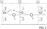
- Figure 3 illustrates electric supply in the door mechanism of Figure 1 .
- Figure 3 shows connection of two PMDC motors on a AC H-bridge, which together with two motor relays 16 and 17 may be integrated into the controller 10.
- a first phase X and a second phase Y supply electricity to the primary motor 8.
- the second phase Y and the third phase Z supply electricity to the secondary motor 9.
- Two first motor relay 16 controls supply of the first phase X and of the second phase Y.
- the second motor relay 17 controls supply of the third phase Z.
- the controller 10 may select to supply both motors 8 and 9 with electricity, or alternatively, only the primary motor 8 with electricity.
Landscapes
- Power-Operated Mechanisms For Wings (AREA)
Abstract
This invention relates to a door mechanism (1) comprising: a drive element (2) which is connected to a door (5) for moving the door. A primary motor (8) rotates the primary pulley (3) and moves the drive element (2). Also a secondary motor (9) rotates a secondary pulley (4) and moves the drive element (2). To obtain a cost efficient and energy efficient door mechanism, the controller (10) controls supply of electricity to the primary motor (8) and the secondary motor (9) independently of each other such that mainly electricity is supplied to the primary motor only, and such that electricity is supplied simultaneously to both to the primary motor (8) and secondary motor (9) only in predetermined situations.
Description
- This invention relates to a door mechanism and more particularly to a mechanism capable of moving a door and to a control method.
- Previously there is known a door mechanism including a drive element and two electric motors which are driven together by a controller when the door needs to be moved. The electric motors are driven simultaneously for moving the door.
- In the above mentioned known solution the maximum speed of the door and the maximum torque available is dependent on what the electric motors together can provide. In praxis the maximum torque is needed in predetermined situations which occur for a very short moment, when considering the entire time period during which the door is moved. This maximum torque needs, however, to be taken into consideration when selecting appropriate motors in order to ensure that the motors are dimensioned to be large enough.
- Consequently, in the known solution relatively large motors need to be selected and these motors run together and consume electricity for the time period during which the door moves. This increases the costs of the door mechanism and results in a solution with a poor energy efficiency.
- An object of the present invention is to solve the above mentioned drawback and to provide a door mechanism with an improved energy efficiency and lower costs. This object is achieved with the door mechanism according to
independent claim 1 and with the control method according toindependent claim 11. - A door mechanism where a controller controls supply of electricity to the primary motor and to the secondary motor independently of each other such that electricity is supplied simultaneously to both the primary and the secondary motor only in predetermined situations, makes it possible to obtain a better energy efficiency and lower costs, as it is no longer necessary to continuously supply energy to both motors.
- Preferred embodiments of the invention are disclosed in the dependent claims.
- In the following the present invention will be described in closer detail by way of example and with reference to the attached drawings, in which
-
Figure 1 illustrates an embodiment of a door mechanism, -
Figure 2 illustrates the torque and speed during movement of the door ofFigure 1 , and -
Figure 3 illustrates electric supply in the door mechanism ofFigure 1 . -
Figure 1 illustrates an embodiment of adoor mechanism 1. In the illustrated example it is by way of example assumed that the door mechanism is for a sliding door. However, in praxis the door mechanism may be utilized also for other door types, such as for swing doors, for instance. - The
door mechanism 1 comprises adrive element 2 which is movably arranged to extend between aprimary pulley 3 and asecondary pulley 4. Thedrive element 4, which in praxis may be implemented with an endless belt, such as a toothed belt, is connected by abracket 7 to adoor 5 for moving the door between a closedposition 12 and anopen position 13, as illustrated byarrow 6. - A
primary motor 8 rotates theprimary pulley 3 and moves thedrive element 2 and simultaneously also thedoor 5. Asecondary motor 9 rotates thesecondary pulley 4 and moves thedrive element 2 and simultaneously also thedoor 5. Acontroller 10 controls supply of electricity from apower supply 11 to theprimary motor 8 and thesecondary motor 9. - The electric supply to the
primary motor 8 and thesecondary motor 9 is implemented independently from each other. Mainly, electricity is supplied only to theprimary motor 8 while the electric supply to the secondary motor is switched off. Typically, the electric supply to thesecondary motor 9 is switched off while thedoor 5 moves with a constant speed or when thedoor 5 has reached a predetermined position. To maintain a constant speed, for instance, it is sufficient that only theprimary motor 8 participates in driving thedrive element 2 and in order to obtain a good energy efficiency it is advantageous to switch off electric supply to thesecondary motor 9 during these time periods. - In predetermined situations, such as during acceleration of the
drive element 2 and thedoor 5 for opening or closing the door, thecontroller 10 controls supply of energy simultaneously to both theprimary motor 8 and to thesecondary motor 9. In this way, when needed, additional power and torque is available to obtain a fast acceleration of even a heavy door (more than 300 kg, for instance). Once a predetermined speed which is an optimal speed for the door in question has been reached, thecontroller 10 switches off supply of electricity to thesecondary motor 9 and continues supply of electricity to theprimary motor 8 only. Alternatively, supply of electricity to thesecondary motor 9 can be switched off once thedoor 5 has reached a predetermined position, for instance. - The
motor controller 10 can be implemented with an AC drive output having a triple-H bridge powering 3 phases. The motors driven by the controller can be AC synchronous motors or PMDC synchronous motors (Permanent Magnet DC motors). The controller can drive theprimary motor 8 and thesecondary motor 9 with a second phase common to both motors. The first and third phases can be connected via motor relays to one of the motors each. In such an implementation the common second phase can be kept at about 50% duty cycle of the PWM (Pulse Width Modulation). The first phase and third phase may be used in combination with the common second phase to drive both motors with active speed and torque control, enabling maximum motor torque. Once thedrive element 2 and thedoor 5 has reached a predefined speed or position, thesecondary motor 9 is switched off by disabling the phase (first or third) connected to it alone. The rest of the movement is carried out by theprimary motor 8 only by the common phase and the phase (the other one of the first or third) connected to it alone. - Additionally, the
motor controller 10 may be provided with a programmable part including a memory, a processor and control circuits, for instance, which facilitate for a user to store parameters and possibly software controlling the supply of electricity for the installation in question. Additionally the controller may handle door commands forwarded to the controller from one or more triggers or sensors arranged such that a user can trigger opening and/or closing of the door. - In the solution according to the illustrated embodiment, advantageously the combination of the
secondary pulley 4 and thesecondary motor 9 are dimensioned to provide a larger torque than the combination of theprimary pulley 3 and theprimary motor 8. In this way the primary motor can be used to ensure that a suitable speed range is covered for the door, while the secondary motor can be used to ensure that an appropriate torque range is provided. Such a solution can be achieved by utilizing asecondary pulley 4 having a smaller diameter D2 than the diameter D1 of theprimary pulley 3. In this way a larger torque is obtained from the combination of thesecondary motor 9 and thesecondary pulley 4, even though the properties of thesecondary motor 9 would correspond to the properties of theprimary motor 8. Naturally, as an alternative to this, it is possible to use a secondary pulley having the same diameter as the primary pulley, and instead obtain a larger torque from the combination of the secondary pulley and secondary motor by selecting a secondary motor which is more powerful that the primary motor. -
Figure 2 illustrates the torque and speed during movement of thedoor 5 ofFigure 1 . - In
Figure 2 line 14 illustrates the speed V of thedoor 5 at different moments of time t0 - t10 while the door moves between a closedposition 12 and anopen position 13, or vice versa.Line 15 illustrates the available torque T to drive the drive element and the door at different moments of time. - From
Figure 2 it can be seen, that during the acceleration phase between moments t0 and t1 both theprimary motor 8 and thesecondary motor 9 are supplied with electricity, and the torque T accelerating the drive element and the door is consequently very high as both motors participate in generating this torque. - At moment t1 a predetermined speed V has been reached. Alternatively the door may have reached a position from where further acceleration is unnecessary, or if needed, further acceleration can be achieved by means of the primary motor only. At that moment the
controller 10 switches off supply of electricity to thesecondary motor 9, which can be seen inFigure 2 as a substantial reduction of the torque T illustrated byline 15. From that moment theprimary motor 8 alone is provided with electricity which is sufficient, asline 14 indicates that the speed still slightly increases after moment t1, and after that, the speed remains constant until reduction of speed occurs at the end of the movement of the door. -
Figure 3 illustrates electric supply in the door mechanism ofFigure 1 .Figure 3 shows connection of two PMDC motors on a AC H-bridge, which together with twomotor relays controller 10. - A first phase X and a second phase Y supply electricity to the
primary motor 8. The second phase Y and the third phase Z supply electricity to thesecondary motor 9. - Two
first motor relay 16 controls supply of the first phase X and of the second phase Y. Thesecond motor relay 17 controls supply of the third phase Z. In this way, by appropriately controlling the first and second motor relays 16 and 17, thecontroller 10 may select to supply bothmotors primary motor 8 with electricity. - It is to be understood that the above description and the accompanying figures are only intended to illustrate the present invention. It will be obvious to a person skilled in the art that the invention can be varied and modified without departing from the scope of the invention.
Claims (13)
- A door mechanism (1) comprising:a drive element (2) which movably extends between a primary pulley (3) and a secondary pulley (4) and which is connected to a door (5) for moving the door,a primary motor (8) for rotating the primary pulley (3) and moving the drive element (2),a secondary motor (9) for rotating the secondary pulley (4) and moving the drive element (2), anda controller (10) controlling supply of electricity to the primary motor (8) and to the secondary motor (9), characterized in thatthe controller (10) controls supply of electricity to the primary motor (8) and the secondary motor (9) independently of each other such that mainly electricity is supplied to the primary motor only, and such that electricity is supplied simultaneously to both to the primary motor (8) and secondary motor (9) only in predetermined situations.
- The door mechanism according to claim 1, wherein the controller (10) controls supply of electricity such that electricity is supplied to both the primary motor (8) and to the secondary motor (9) simultaneously during acceleration of the drive element (2).
- The door mechanism according to claim 1 or 2, wherein the controller (10) controls supply of electricity by switching off supply of electricity to the secondary motor (9) and by continuing supply of electricity to the primary motor (8) when drive element has reached a predetermined speed or the door (5) has reached a predetermined position.
- The door mechanism according to one of claims 1 to 3, wherein
the combination of the secondary pulley (4) and secondary motor (9) are dimensioned to provide a larger torque than the combination of the primary pulley (3) and the primary motor (8). - The door mechanism according to one of claims 1 to 4, wherein
the primary motor (8) and the secondary motor (9) provide an equal torque, and
the diameter (D2) of the secondary pulley (4) is smaller that the diameter (D1) of the primary pulley (3). - The door mechanism according to one of claims 1 to 5, wherein the drive element (2) is an endless belt.
- The door mechanism according to one of claims 1 to 6, wherein the door mechanism (1) is a mechanism for a slide door or for a swing door.
- The door mechanism according to one of claims 1 to 7, wherein
the primary motor (8) is supplied with electricity by a first (X) and a second phase (Y),
the secondary motor (9) is supplied with electricity by the second phase (Y) and a third phase (Z), and
the controller (10) controls supply of electricity to the secondary motor (9) via the third phase (Z) only in said predetermined situations. - The door mechanism according to claim 8, wherein the door mechanism comprises a first relay (16) and second relay (17) controlling supply of the first, second and third phase to the primary motor (8) and secondary motor (9).
- The door mechanism according to claim 9, wherein the door mechanism (1) comprises a triple H-bridge providing the first (X), second (Y) and third (Y) phase to the primary motor (8) and the secondary motor (9).
- A method for controlling a primary motor (8) and a secondary motor (9) of a door mechanism, characterized in that the method comprises:supplying electricity independently to the primary motor (8) and to the secondary motor (9), bysupplying electricity mainly only to the primary motor (9), andsupplying electricity simultaneously to both the primary motor (8) and to the secondary motor (9) only in predetermined situations.
- The method according to claim 11, wherein
electricity is supplied to both the primary motor (8) and to the secondary motor (9) simultaneously during acceleration of a door operated by the door (5) mechanism. - The method according to claim 11 or 12, wherein
supply of electricity to the secondary motor (9) is switched off and supply of electricity to the primary motor (8) only is continued when a door (5) operated by the door mechanism has reached a predetermined speed or the door (5) has reached a predetermined position.
Priority Applications (1)
| Application Number | Priority Date | Filing Date | Title |
|---|---|---|---|
| EP17192032.5A EP3460159A1 (en) | 2017-09-20 | 2017-09-20 | A door mechanism and a control method |
Applications Claiming Priority (1)
| Application Number | Priority Date | Filing Date | Title |
|---|---|---|---|
| EP17192032.5A EP3460159A1 (en) | 2017-09-20 | 2017-09-20 | A door mechanism and a control method |
Publications (1)
| Publication Number | Publication Date |
|---|---|
| EP3460159A1 true EP3460159A1 (en) | 2019-03-27 |
Family
ID=59923289
Family Applications (1)
| Application Number | Title | Priority Date | Filing Date |
|---|---|---|---|
| EP17192032.5A Withdrawn EP3460159A1 (en) | 2017-09-20 | 2017-09-20 | A door mechanism and a control method |
Country Status (1)
| Country | Link |
|---|---|
| EP (1) | EP3460159A1 (en) |
Citations (2)
| Publication number | Priority date | Publication date | Assignee | Title |
|---|---|---|---|---|
| EP0947658A2 (en) * | 1998-03-28 | 1999-10-06 | GEZE GmbH | Drive for a door |
| DE19835632C1 (en) * | 1998-08-06 | 1999-12-09 | Agta Record Ag Fehraltorf | Automatic door drive, esp. for a sliding door with at least one door panel |
-
2017
- 2017-09-20 EP EP17192032.5A patent/EP3460159A1/en not_active Withdrawn
Patent Citations (2)
| Publication number | Priority date | Publication date | Assignee | Title |
|---|---|---|---|---|
| EP0947658A2 (en) * | 1998-03-28 | 1999-10-06 | GEZE GmbH | Drive for a door |
| DE19835632C1 (en) * | 1998-08-06 | 1999-12-09 | Agta Record Ag Fehraltorf | Automatic door drive, esp. for a sliding door with at least one door panel |
Similar Documents
| Publication | Publication Date | Title |
|---|---|---|
| US6741050B2 (en) | Method of controlling and switching for braking an electronically commutated electrical motor | |
| JP7464357B2 (en) | Short circuit brake for long stator linear motor | |
| EP3150335B1 (en) | Power tool with a control unit | |
| US11173584B2 (en) | Waveform shaping in power tool powered by alternating-current power supply | |
| WO2005002036A3 (en) | Position sensorless control algorithm for ac machine | |
| GB2455631A (en) | Control of motors using open and closed loop controllers | |
| US8884562B1 (en) | Current control in brushless DC motors | |
| DE602004016410D1 (en) | Motor driving device | |
| MY126919A (en) | Starting control method of and control apparatus for synchronous motor, and air conditioner, refrigerator, washing machine and vacuum cleaner each provided with the control apparatus | |
| WO2008094762A3 (en) | Method and apparatus for battery-backed power supply and battery charging | |
| WO2003100957A3 (en) | Method, apparatus, and system for drive control, power conversion, and start-up control | |
| JP2004140995A5 (en) | ||
| WO2004082119A3 (en) | Control circuit for a switched mode power supply unit | |
| CN106337618B (en) | Operate sub-controlling unit | |
| JPH08259139A (en) | Emergency operation device of elevator motor | |
| US20160336793A1 (en) | On-Board Battery Charging and Regenerative Braking | |
| PL1695437T3 (en) | Control for a brushless dc motor | |
| JP2008296323A5 (en) | ||
| MY203251A (en) | Air compressor and control method of air compressor | |
| EP3295537B1 (en) | On-board battery charging and regenerative braking | |
| JP4901555B2 (en) | refrigerator | |
| US7474074B2 (en) | Variable speed induction motor with wye-delta switching with reduced drive volt-amp requirement | |
| JP2008005656A (en) | Automatic opening/closing device for vehicle | |
| JP2005217774A5 (en) | ||
| JP3124474U (en) | Brushless DC motor controller |
Legal Events
| Date | Code | Title | Description |
|---|---|---|---|
| PUAI | Public reference made under article 153(3) epc to a published international application that has entered the european phase |
Free format text: ORIGINAL CODE: 0009012 |
|
| AK | Designated contracting states |
Kind code of ref document: A1 Designated state(s): AL AT BE BG CH CY CZ DE DK EE ES FI FR GB GR HR HU IE IS IT LI LT LU LV MC MK MT NL NO PL PT RO RS SE SI SK SM TR |
|
| AX | Request for extension of the european patent |
Extension state: BA ME |
|
| STAA | Information on the status of an ep patent application or granted ep patent |
Free format text: STATUS: THE APPLICATION IS DEEMED TO BE WITHDRAWN |
|
| 18D | Application deemed to be withdrawn |
Effective date: 20190928 |