EP3459801A1 - Electric brake system and operating methods thereof - Google Patents
Electric brake system and operating methods thereof Download PDFInfo
- Publication number
- EP3459801A1 EP3459801A1 EP18196503.9A EP18196503A EP3459801A1 EP 3459801 A1 EP3459801 A1 EP 3459801A1 EP 18196503 A EP18196503 A EP 18196503A EP 3459801 A1 EP3459801 A1 EP 3459801A1
- Authority
- EP
- European Patent Office
- Prior art keywords
- hydraulic
- pressure
- flow path
- valve
- chamber
- Prior art date
- Legal status (The legal status is an assumption and is not a legal conclusion. Google has not performed a legal analysis and makes no representation as to the accuracy of the status listed.)
- Granted
Links
- 238000011017 operating method Methods 0.000 title claims abstract description 23
- 238000006073 displacement reaction Methods 0.000 claims abstract description 32
- 238000007689 inspection Methods 0.000 claims abstract description 14
- 230000002159 abnormal effect Effects 0.000 claims abstract description 5
- 238000004088 simulation Methods 0.000 claims description 65
- 238000006243 chemical reaction Methods 0.000 claims description 19
- 241000931526 Acer campestre Species 0.000 claims description 3
- 230000004044 response Effects 0.000 abstract description 8
- 238000007599 discharging Methods 0.000 abstract 1
- 238000010586 diagram Methods 0.000 description 30
- 238000004891 communication Methods 0.000 description 20
- 238000007789 sealing Methods 0.000 description 10
- 238000000034 method Methods 0.000 description 3
- 230000008859 change Effects 0.000 description 2
- 230000006835 compression Effects 0.000 description 2
- 238000007906 compression Methods 0.000 description 2
- 230000006837 decompression Effects 0.000 description 2
- 230000000694 effects Effects 0.000 description 2
- 238000005516 engineering process Methods 0.000 description 2
- 239000000463 material Substances 0.000 description 2
- 230000009467 reduction Effects 0.000 description 2
- 230000007257 malfunction Effects 0.000 description 1
- 230000007246 mechanism Effects 0.000 description 1
- 230000008569 process Effects 0.000 description 1
- 238000011144 upstream manufacturing Methods 0.000 description 1
Images


Classifications
-
- B—PERFORMING OPERATIONS; TRANSPORTING
- B60—VEHICLES IN GENERAL
- B60T—VEHICLE BRAKE CONTROL SYSTEMS OR PARTS THEREOF; BRAKE CONTROL SYSTEMS OR PARTS THEREOF, IN GENERAL; ARRANGEMENT OF BRAKING ELEMENTS ON VEHICLES IN GENERAL; PORTABLE DEVICES FOR PREVENTING UNWANTED MOVEMENT OF VEHICLES; VEHICLE MODIFICATIONS TO FACILITATE COOLING OF BRAKES
- B60T13/00—Transmitting braking action from initiating means to ultimate brake actuator with power assistance or drive; Brake systems incorporating such transmitting means, e.g. air-pressure brake systems
- B60T13/10—Transmitting braking action from initiating means to ultimate brake actuator with power assistance or drive; Brake systems incorporating such transmitting means, e.g. air-pressure brake systems with fluid assistance, drive, or release
- B60T13/66—Electrical control in fluid-pressure brake systems
- B60T13/662—Electrical control in fluid-pressure brake systems characterised by specified functions of the control system components
-
- B—PERFORMING OPERATIONS; TRANSPORTING
- B60—VEHICLES IN GENERAL
- B60T—VEHICLE BRAKE CONTROL SYSTEMS OR PARTS THEREOF; BRAKE CONTROL SYSTEMS OR PARTS THEREOF, IN GENERAL; ARRANGEMENT OF BRAKING ELEMENTS ON VEHICLES IN GENERAL; PORTABLE DEVICES FOR PREVENTING UNWANTED MOVEMENT OF VEHICLES; VEHICLE MODIFICATIONS TO FACILITATE COOLING OF BRAKES
- B60T13/00—Transmitting braking action from initiating means to ultimate brake actuator with power assistance or drive; Brake systems incorporating such transmitting means, e.g. air-pressure brake systems
- B60T13/10—Transmitting braking action from initiating means to ultimate brake actuator with power assistance or drive; Brake systems incorporating such transmitting means, e.g. air-pressure brake systems with fluid assistance, drive, or release
- B60T13/66—Electrical control in fluid-pressure brake systems
- B60T13/68—Electrical control in fluid-pressure brake systems by electrically-controlled valves
- B60T13/686—Electrical control in fluid-pressure brake systems by electrically-controlled valves in hydraulic systems or parts thereof
-
- B—PERFORMING OPERATIONS; TRANSPORTING
- B60—VEHICLES IN GENERAL
- B60T—VEHICLE BRAKE CONTROL SYSTEMS OR PARTS THEREOF; BRAKE CONTROL SYSTEMS OR PARTS THEREOF, IN GENERAL; ARRANGEMENT OF BRAKING ELEMENTS ON VEHICLES IN GENERAL; PORTABLE DEVICES FOR PREVENTING UNWANTED MOVEMENT OF VEHICLES; VEHICLE MODIFICATIONS TO FACILITATE COOLING OF BRAKES
- B60T13/00—Transmitting braking action from initiating means to ultimate brake actuator with power assistance or drive; Brake systems incorporating such transmitting means, e.g. air-pressure brake systems
- B60T13/10—Transmitting braking action from initiating means to ultimate brake actuator with power assistance or drive; Brake systems incorporating such transmitting means, e.g. air-pressure brake systems with fluid assistance, drive, or release
- B60T13/12—Transmitting braking action from initiating means to ultimate brake actuator with power assistance or drive; Brake systems incorporating such transmitting means, e.g. air-pressure brake systems with fluid assistance, drive, or release the fluid being liquid
- B60T13/16—Transmitting braking action from initiating means to ultimate brake actuator with power assistance or drive; Brake systems incorporating such transmitting means, e.g. air-pressure brake systems with fluid assistance, drive, or release the fluid being liquid using pumps directly, i.e. without interposition of accumulators or reservoirs
- B60T13/161—Systems with master cylinder
- B60T13/165—Master cylinder integrated or hydraulically coupled with booster
-
- B—PERFORMING OPERATIONS; TRANSPORTING
- B60—VEHICLES IN GENERAL
- B60T—VEHICLE BRAKE CONTROL SYSTEMS OR PARTS THEREOF; BRAKE CONTROL SYSTEMS OR PARTS THEREOF, IN GENERAL; ARRANGEMENT OF BRAKING ELEMENTS ON VEHICLES IN GENERAL; PORTABLE DEVICES FOR PREVENTING UNWANTED MOVEMENT OF VEHICLES; VEHICLE MODIFICATIONS TO FACILITATE COOLING OF BRAKES
- B60T13/00—Transmitting braking action from initiating means to ultimate brake actuator with power assistance or drive; Brake systems incorporating such transmitting means, e.g. air-pressure brake systems
- B60T13/10—Transmitting braking action from initiating means to ultimate brake actuator with power assistance or drive; Brake systems incorporating such transmitting means, e.g. air-pressure brake systems with fluid assistance, drive, or release
- B60T13/58—Combined or convertible systems
-
- B—PERFORMING OPERATIONS; TRANSPORTING
- B60—VEHICLES IN GENERAL
- B60T—VEHICLE BRAKE CONTROL SYSTEMS OR PARTS THEREOF; BRAKE CONTROL SYSTEMS OR PARTS THEREOF, IN GENERAL; ARRANGEMENT OF BRAKING ELEMENTS ON VEHICLES IN GENERAL; PORTABLE DEVICES FOR PREVENTING UNWANTED MOVEMENT OF VEHICLES; VEHICLE MODIFICATIONS TO FACILITATE COOLING OF BRAKES
- B60T13/00—Transmitting braking action from initiating means to ultimate brake actuator with power assistance or drive; Brake systems incorporating such transmitting means, e.g. air-pressure brake systems
- B60T13/74—Transmitting braking action from initiating means to ultimate brake actuator with power assistance or drive; Brake systems incorporating such transmitting means, e.g. air-pressure brake systems with electrical assistance or drive
- B60T13/745—Transmitting braking action from initiating means to ultimate brake actuator with power assistance or drive; Brake systems incorporating such transmitting means, e.g. air-pressure brake systems with electrical assistance or drive acting on a hydraulic system, e.g. a master cylinder
-
- B—PERFORMING OPERATIONS; TRANSPORTING
- B60—VEHICLES IN GENERAL
- B60T—VEHICLE BRAKE CONTROL SYSTEMS OR PARTS THEREOF; BRAKE CONTROL SYSTEMS OR PARTS THEREOF, IN GENERAL; ARRANGEMENT OF BRAKING ELEMENTS ON VEHICLES IN GENERAL; PORTABLE DEVICES FOR PREVENTING UNWANTED MOVEMENT OF VEHICLES; VEHICLE MODIFICATIONS TO FACILITATE COOLING OF BRAKES
- B60T15/00—Construction arrangement, or operation of valves incorporated in power brake systems and not covered by groups B60T11/00 or B60T13/00
- B60T15/02—Application and release valves
- B60T15/025—Electrically controlled valves
- B60T15/028—Electrically controlled valves in hydraulic systems
-
- B—PERFORMING OPERATIONS; TRANSPORTING
- B60—VEHICLES IN GENERAL
- B60T—VEHICLE BRAKE CONTROL SYSTEMS OR PARTS THEREOF; BRAKE CONTROL SYSTEMS OR PARTS THEREOF, IN GENERAL; ARRANGEMENT OF BRAKING ELEMENTS ON VEHICLES IN GENERAL; PORTABLE DEVICES FOR PREVENTING UNWANTED MOVEMENT OF VEHICLES; VEHICLE MODIFICATIONS TO FACILITATE COOLING OF BRAKES
- B60T17/00—Component parts, details, or accessories of power brake systems not covered by groups B60T8/00, B60T13/00 or B60T15/00, or presenting other characteristic features
- B60T17/18—Safety devices; Monitoring
- B60T17/22—Devices for monitoring or checking brake systems; Signal devices
- B60T17/221—Procedure or apparatus for checking or keeping in a correct functioning condition of brake systems
-
- B—PERFORMING OPERATIONS; TRANSPORTING
- B60—VEHICLES IN GENERAL
- B60T—VEHICLE BRAKE CONTROL SYSTEMS OR PARTS THEREOF; BRAKE CONTROL SYSTEMS OR PARTS THEREOF, IN GENERAL; ARRANGEMENT OF BRAKING ELEMENTS ON VEHICLES IN GENERAL; PORTABLE DEVICES FOR PREVENTING UNWANTED MOVEMENT OF VEHICLES; VEHICLE MODIFICATIONS TO FACILITATE COOLING OF BRAKES
- B60T7/00—Brake-action initiating means
- B60T7/02—Brake-action initiating means for personal initiation
- B60T7/04—Brake-action initiating means for personal initiation foot actuated
- B60T7/042—Brake-action initiating means for personal initiation foot actuated by electrical means, e.g. using travel or force sensors
-
- B—PERFORMING OPERATIONS; TRANSPORTING
- B60—VEHICLES IN GENERAL
- B60T—VEHICLE BRAKE CONTROL SYSTEMS OR PARTS THEREOF; BRAKE CONTROL SYSTEMS OR PARTS THEREOF, IN GENERAL; ARRANGEMENT OF BRAKING ELEMENTS ON VEHICLES IN GENERAL; PORTABLE DEVICES FOR PREVENTING UNWANTED MOVEMENT OF VEHICLES; VEHICLE MODIFICATIONS TO FACILITATE COOLING OF BRAKES
- B60T8/00—Arrangements for adjusting wheel-braking force to meet varying vehicular or ground-surface conditions, e.g. limiting or varying distribution of braking force
- B60T8/17—Using electrical or electronic regulation means to control braking
-
- B—PERFORMING OPERATIONS; TRANSPORTING
- B60—VEHICLES IN GENERAL
- B60T—VEHICLE BRAKE CONTROL SYSTEMS OR PARTS THEREOF; BRAKE CONTROL SYSTEMS OR PARTS THEREOF, IN GENERAL; ARRANGEMENT OF BRAKING ELEMENTS ON VEHICLES IN GENERAL; PORTABLE DEVICES FOR PREVENTING UNWANTED MOVEMENT OF VEHICLES; VEHICLE MODIFICATIONS TO FACILITATE COOLING OF BRAKES
- B60T8/00—Arrangements for adjusting wheel-braking force to meet varying vehicular or ground-surface conditions, e.g. limiting or varying distribution of braking force
- B60T8/32—Arrangements for adjusting wheel-braking force to meet varying vehicular or ground-surface conditions, e.g. limiting or varying distribution of braking force responsive to a speed condition, e.g. acceleration or deceleration
- B60T8/34—Arrangements for adjusting wheel-braking force to meet varying vehicular or ground-surface conditions, e.g. limiting or varying distribution of braking force responsive to a speed condition, e.g. acceleration or deceleration having a fluid pressure regulator responsive to a speed condition
- B60T8/341—Systems characterised by their valves
-
- B—PERFORMING OPERATIONS; TRANSPORTING
- B60—VEHICLES IN GENERAL
- B60T—VEHICLE BRAKE CONTROL SYSTEMS OR PARTS THEREOF; BRAKE CONTROL SYSTEMS OR PARTS THEREOF, IN GENERAL; ARRANGEMENT OF BRAKING ELEMENTS ON VEHICLES IN GENERAL; PORTABLE DEVICES FOR PREVENTING UNWANTED MOVEMENT OF VEHICLES; VEHICLE MODIFICATIONS TO FACILITATE COOLING OF BRAKES
- B60T8/00—Arrangements for adjusting wheel-braking force to meet varying vehicular or ground-surface conditions, e.g. limiting or varying distribution of braking force
- B60T8/32—Arrangements for adjusting wheel-braking force to meet varying vehicular or ground-surface conditions, e.g. limiting or varying distribution of braking force responsive to a speed condition, e.g. acceleration or deceleration
- B60T8/34—Arrangements for adjusting wheel-braking force to meet varying vehicular or ground-surface conditions, e.g. limiting or varying distribution of braking force responsive to a speed condition, e.g. acceleration or deceleration having a fluid pressure regulator responsive to a speed condition
- B60T8/40—Arrangements for adjusting wheel-braking force to meet varying vehicular or ground-surface conditions, e.g. limiting or varying distribution of braking force responsive to a speed condition, e.g. acceleration or deceleration having a fluid pressure regulator responsive to a speed condition comprising an additional fluid circuit including fluid pressurising means for modifying the pressure of the braking fluid, e.g. including wheel driven pumps for detecting a speed condition, or pumps which are controlled by means independent of the braking system
- B60T8/4072—Systems in which a driver input signal is used as a control signal for the additional fluid circuit which is normally used for braking
- B60T8/4081—Systems with stroke simulating devices for driver input
- B60T8/409—Systems with stroke simulating devices for driver input characterised by details of the stroke simulating device
-
- B—PERFORMING OPERATIONS; TRANSPORTING
- B60—VEHICLES IN GENERAL
- B60T—VEHICLE BRAKE CONTROL SYSTEMS OR PARTS THEREOF; BRAKE CONTROL SYSTEMS OR PARTS THEREOF, IN GENERAL; ARRANGEMENT OF BRAKING ELEMENTS ON VEHICLES IN GENERAL; PORTABLE DEVICES FOR PREVENTING UNWANTED MOVEMENT OF VEHICLES; VEHICLE MODIFICATIONS TO FACILITATE COOLING OF BRAKES
- B60T2270/00—Further aspects of brake control systems not otherwise provided for
- B60T2270/10—ABS control systems
-
- B—PERFORMING OPERATIONS; TRANSPORTING
- B60—VEHICLES IN GENERAL
- B60T—VEHICLE BRAKE CONTROL SYSTEMS OR PARTS THEREOF; BRAKE CONTROL SYSTEMS OR PARTS THEREOF, IN GENERAL; ARRANGEMENT OF BRAKING ELEMENTS ON VEHICLES IN GENERAL; PORTABLE DEVICES FOR PREVENTING UNWANTED MOVEMENT OF VEHICLES; VEHICLE MODIFICATIONS TO FACILITATE COOLING OF BRAKES
- B60T2270/00—Further aspects of brake control systems not otherwise provided for
- B60T2270/40—Failsafe aspects of brake control systems
- B60T2270/402—Back-up
-
- B—PERFORMING OPERATIONS; TRANSPORTING
- B60—VEHICLES IN GENERAL
- B60T—VEHICLE BRAKE CONTROL SYSTEMS OR PARTS THEREOF; BRAKE CONTROL SYSTEMS OR PARTS THEREOF, IN GENERAL; ARRANGEMENT OF BRAKING ELEMENTS ON VEHICLES IN GENERAL; PORTABLE DEVICES FOR PREVENTING UNWANTED MOVEMENT OF VEHICLES; VEHICLE MODIFICATIONS TO FACILITATE COOLING OF BRAKES
- B60T2270/00—Further aspects of brake control systems not otherwise provided for
- B60T2270/40—Failsafe aspects of brake control systems
- B60T2270/404—Brake-by-wire or X-by-wire failsafe
-
- B—PERFORMING OPERATIONS; TRANSPORTING
- B60—VEHICLES IN GENERAL
- B60T—VEHICLE BRAKE CONTROL SYSTEMS OR PARTS THEREOF; BRAKE CONTROL SYSTEMS OR PARTS THEREOF, IN GENERAL; ARRANGEMENT OF BRAKING ELEMENTS ON VEHICLES IN GENERAL; PORTABLE DEVICES FOR PREVENTING UNWANTED MOVEMENT OF VEHICLES; VEHICLE MODIFICATIONS TO FACILITATE COOLING OF BRAKES
- B60T2270/00—Further aspects of brake control systems not otherwise provided for
- B60T2270/40—Failsafe aspects of brake control systems
- B60T2270/406—Test-mode; Self-diagnosis
-
- B—PERFORMING OPERATIONS; TRANSPORTING
- B60—VEHICLES IN GENERAL
- B60T—VEHICLE BRAKE CONTROL SYSTEMS OR PARTS THEREOF; BRAKE CONTROL SYSTEMS OR PARTS THEREOF, IN GENERAL; ARRANGEMENT OF BRAKING ELEMENTS ON VEHICLES IN GENERAL; PORTABLE DEVICES FOR PREVENTING UNWANTED MOVEMENT OF VEHICLES; VEHICLE MODIFICATIONS TO FACILITATE COOLING OF BRAKES
- B60T2270/00—Further aspects of brake control systems not otherwise provided for
- B60T2270/82—Brake-by-Wire, EHB
Abstract
Description
- This application is based on and claims priority under 35 U.S.C. §119 to Korean Patent Application No.
10-2017-0127467 10-2017-0123547, filed on May 17, 2017 - The disclosure relates to an electric brake system and an operating method thereof, more particularly, to an electric brake system configured to generate a braking force using an electrical signal corresponding to displacement of a brake pedal and an operating method thereof.
- A vehicle is essentially equipped with a brake system for braking. Recently, various types of brake systems have been proposed for the safety of driver and passenger.
- According to a conventional brake system, a hydraulic pressure for braking is supplied to a wheel cylinder by a booster, which is mechanically connected, upon stepping a brake pedal by a driver. However, since there is a growing need of various braking functions that accurately correspond to vehicle operating conditions, the electric brake system having a hydraulic pressure supplier has been widely used, wherein the hydraulic pressure supplier is configured to supply hydraulic pressure for braking to the wheel cylinder by receiving an electrical signal corresponding to a braking intention of a driver, from a pedal displacement sensor detecting displacement of a pedal when a driver presses the brake pedal.
- When the electric brake system is in a normal operation mode, the brake pedal operation of the driver leads to the generation and the provision of the electrical signal. Accordingly, the hydraulic supplier is electrically operated and controlled to generate a hydraulic pressure for braking and transmit the hydraulic pressure to the wheel cylinder. As mentioned above, since the electric brake system is electrically operated and controlled, the electric brake system can implement complicated and various braking operations. However, when a technical problem occurs in a component of automotive electronics, a hydraulic pressure for braking is not stably formed and it threatens the safety of the passenger.
- Therefore, the electric brake system may be switched to an abnormal operation mode when one component element fails or is out of control. In this case, a mechanism is required in which the operation of the driver's brake pedal must be directly linked to the wheel cylinder. That is, in the abnormal operation mode of the electric brake system, as the driver applies pressure to the brake pedal, the hydraulic pressure for braking should be directly generated and directly transmitted to the wheel cylinder.
-
EP 2 520 473 A1 (Honda Motor Co., Ltd.) 2012. 11. 7. - Therefore, it is an aspect of the present disclosure to provide an electric brake system capable of stably providing a braking pressure of a vehicle, and an operating method thereof.
- It is another aspect of the present disclosure to provide an electric brake system capable of improving the product productivity by simplifying a structure and by reducing the number of valves, and an operating method thereof.
- It is another aspect of the present disclosure to provide an electric brake system capable of providing the stable braking effect in various operating conditions of the vehicle and an operating method thereof.
- It is another aspect of the present disclosure to provide an electric brake system capable of having an improved performance and operational reliability, and an operating method thereof.
- It is another aspect of the present disclosure to provide an electric brake system capable of having an improved durability of the product, and an operating method thereof.
- It is another aspect of the present disclosure to provide an electric brake system capable of reducing the size of the product, and an operating method thereof.
- Additional aspects of the present disclosure will be set forth in part in the description which follows and, in part, will be obvious from the description, or may be learned by practice of the present disclosure.
- In accordance with an aspect of the disclosure, an electric brake system includes a hydraulic supplier configured to generate hydraulic pressure by operating a hydraulic piston by an electrical signal, which is output corresponding to a displacement of a brake pedal, and provided with a first pressure chamber provided on one side of the hydraulic piston movably accommodated in a cylinder block and a second pressure chamber provided on the other side of the hydraulic piston; and a hydraulic control unit provided with a first hydraulic circuit configured to control hydraulic pressure transmitted to two wheel cylinders, and a second hydraulic circuit configured to control hydraulic pressure transmitted to other two wheel cylinders. The hydraulic control unit includes a first hydraulic flow path communicated with the first pressure chamber, a second hydraulic flow path diverged from the first hydraulic flow path, a third hydraulic flow path diverged from the first hydraulic flow path and then connected to the second hydraulic circuit, a fourth hydraulic flow path communicated with the second pressure chamber and connected to the first hydraulic circuit, a fifth hydraulic flow path configured to connect the second hydraulic flow path to the first hydraulic circuit and the fourth hydraulic flow path, and a sixth hydraulic flow path configured to connect the second hydraulic flow path to the third hydraulic flow path.
- The hydraulic control unit may include a first valve disposed on the second hydraulic flow path to control a flow of pressure medium, a second valve disposed on the third hydraulic flow path to control a flow of pressure medium, a third valve disposed on the fourth hydraulic flow path to control a flow of pressure medium, and a fourth valve disposed on the sixth hydraulic flow path to control a flow of pressure medium.
- The first, third and fourth valves may be provided as a solenoid valve configured to control the flow of the pressure medium in two ways, and the second valve may be provided as a check valve configured to allow only the flow of the pressure medium flowing to the second hydraulic circuit from the first pressure chamber.
- The electric brake system may further include a reservoir configured to store pressure medium; a master cylinder provided with a master chamber and a master piston displaceable by an operation of the brake pedal to compress and discharge the pressure medium accommodated in the master chamber according to a displacement; a simulator provided with a simulation chamber, and a simulation piston displaceable by the pressure medium discharged from the maser chamber to compress and discharge the pressure medium accommodated in the simulation chamber according to a displacement; and a reservoir flow path configured to communicate among the master chamber, the simulation chamber and the reservoir.
- The electric brake system may further include a simulator check valve disposed on the reservoir flow path to allow only the flow of the pressure medium flowing from the reservoir to the master chamber and the simulation chamber; and a simulator valve disposed on a bypass flow path in parallel with the simulator check valve on the reservoir flow path to control the flow of the pressure medium in two ways.
- The master piston may include a first master piston directly pressed by the brake pedal, and a second master piston indirectly pressed by the first master piston. The master chamber may include a first master chamber in which the first master piston is placed, and a second master chamber in which the second master piston is placed. The simulation piston may be configured to be displaceable by the pressure medium compressed and discharged from the first maser chamber, and the reservoir flow path may communicate among the first master chamber, the simulation chamber and the reservoir.
- The simulator may further include a reaction force spring configured to elastically support the simulation piston.
- The electric brake system may further include a first dump flow path configured to connect the first pressure chamber to the reservoir; a second dump flow path configured to connect the second pressure chamber to the reservoir; a first dump valve disposed on the first dump flow path to control the flow of the pressure medium, and provided as a check valve configured to allow only the flow of the pressure medium flowing into the first pressure chamber from the reservoir; a second dump valve disposed on the second dump flow path to control the flow of the pressure medium, and provided as a check valve configured to allow only the flow of the pressure medium flowing into the second pressure chamber from the reservoir; and a third dump valve disposed on a bypass flow path in parallel with the second dump valve on the second dump flow path to control the flow of the pressure, and provided as a solenoid valve configured to control the flow of the pressure medium in two ways between the reservoir and the second pressure chamber.
- The electric brake system may further include a first backup flow path configured to connect the first master chamber to the first hydraulic circuit; a second backup flow path configured to connect the second master chamber to the second hydraulic circuit; a first cut valve provided in the first backup flow path to control the flow of the pressure medium; and a second cut valve provided in the second backup flow path to control the flow of the pressure medium.
- The first and fourth valves may be provided as a solenoid valve configured to control the flow of the pressure medium in two ways, the second valve may be provided as a check valve configured to allow only the flow of the pressure medium flowing to the second hydraulic circuit from the first pressure chamber; and the third valve may be provided as a check valve configured to allow only the flow of the pressure medium flowing to the first hydraulic circuit or the fifth hydraulic flow path from the second pressure chamber.
- The hydraulic control unit may include a first valve disposed on the second hydraulic flow path to control a flow of pressure medium, a second valve disposed on the third hydraulic flow path to control a flow of pressure medium, a third valve disposed on the fourth hydraulic flow path to control a flow of pressure medium, and a fourth valve disposed on the fifth hydraulic flow path to control a flow of pressure medium.
- The first and fourth valves may be provided as a solenoid valve configured to control the flow of the pressure medium in two ways, the second valve may be provided as a check valve configured to allow only the flow of the pressure medium flowing to the second hydraulic circuit from the first pressure chamber; and the third valve may be provided as a check valve configured to allow only the flow of the pressure medium flowing to the first hydraulic circuit or the fifth hydraulic flow path from the second pressure chamber.
- A normal operation mode may include sequentially performing a low pressure mode providing a relatively low hydraulic pressure and a high pressure mode providing a relatively high hydraulic pressure, according to a hydraulic level transmitted to the wheel cylinder from the hydraulic supplier.
- The low pressure mode may include opening the first and fourth valves; and providing hydraulic pressure, which is generated in the first pressure chamber by the forward movement of the hydraulic piston, to the first hydraulic circuit and the second hydraulic circuit.
- The high pressure mode may include opening the first and fourth valves; providing some of hydraulic pressure, which is generated in the first pressure chamber by the forward movement of the hydraulic piston, to the first hydraulic circuit and the second hydraulic circuit after the low pressure mode; opening the third valve; providing some of the remaining hydraulic pressure, which is generated in the first pressure chamber, to the second hydraulic circuit.
- A release of the low pressure mode may include opening the first and fourth valves; and allowing the pressure medium of the first hydraulic circuit and the second hydraulic circuit to be collected to the first pressure chamber by generating a negative pressure in the first pressure chamber by the backward movement of the hydraulic piston.
- A release of the high pressure mode may include opening the first and fourth valves; allowing the pressure medium of the first hydraulic circuit and the second hydraulic circuit to be collected to the first pressure chamber by generating a negative pressure in the first pressure chamber by the backward movement of the hydraulic piston; opening the third valve; and supplying the pressure medium of the second pressure chamber to the first pressure chamber.
- An abnormal operation mode may include communicating the first master chamber with the first hydraulic circuit by opening the first cut valve; and communicating the second master chamber with the second hydraulic circuit by opening the second cut valve.
- A normal operation mode may include opening the simulator valve, generating a displacement of the simulation piston by the pressure medium discharged from the first master chamber; and supplying the pressure medium accommodated in the simulation chamber to the reservoir along the reservoir flow path.
- An inspection mode configured to identify the presence of a leakage in the master cylinder or the simulator valve may include closing the simulator valve and the second cut valve and opening the first cut valve; providing hydraulic pressure, which is generated by operating the hydraulic supplier, to the first master chamber; and comparing a hydraulic pressure value of the pressure medium estimated based on displacement amount of the hydraulic piston, with a hydraulic pressure value of the pressure medium supplied to the first master chamber.
- These and/or other aspects of the disclosure will become apparent and more readily appreciated from the following description of embodiments, taken in conjunction with the accompanying drawings of which:
-
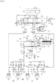
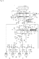
FIG. 1 is a hydraulic circuit diagram illustrating an electric brake system according to a first embodiment; -
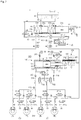
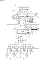
FIG. 2 is a hydraulic circuit diagram illustrating a state in which a hydraulic piston of the electric brake system according to the first embodiment moves forward and provides a braking pressure in a low pressure mode; -
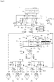
FIG. 3 is a hydraulic circuit diagram illustrating a state in which the hydraulic piston of the electric brake system according to the first embodiment moves forward and provides a braking pressure in a high pressure mode; -
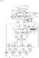
FIG. 4 is a hydraulic circuit diagram illustrating a state in which the hydraulic piston of the electric brake system according to the first embodiment moves backward and provides a braking pressure; -
FIG. 5 is a hydraulic circuit diagram illustrating a state in which the hydraulic piston of the electric brake system according to the first embodiment moves backward and provides a braking pressure in the high pressure mode; -
FIG. 6 is a hydraulic circuit diagram illustrating a state in which the hydraulic piston of the electric brake system according to the first embodiment moves backward and provides a braking pressure in a low pressure mode; -
FIG. 7 is a hydraulic circuit diagram illustrating a state in which the hydraulic piston of the electric brake system according to the first embodiment moves forward and releases a braking pressure; -
FIG. 8 is a hydraulic circuit diagram illustrating a state in which the electric brake system according to the first embodiment is abnormally operated; -
FIG. 9 is a hydraulic circuit diagram illustrating a state in which the electric brake system according to the first embodiment is in an inspection mode; -
FIG. 10 is a hydraulic circuit diagram illustrating an electric brake system according to a second embodiment; -
FIG. 11 is a hydraulic circuit diagram illustrating a state in which a hydraulic piston of the electric brake system according to the second embodiment moves forward and provides a braking pressure; -
FIG. 12 is a hydraulic circuit diagram illustrating a state in which the hydraulic piston of the electric brake system according to the second embodiment moves backward and provides a braking pressure; -
FIG. 13 is a hydraulic circuit diagram illustrating an electric brake system according to a third embodiment; -
FIG. 14 is a hydraulic circuit diagram illustrating a state in which a hydraulic piston of the electric brake system according to the third embodiment moves forward and provides a braking pressure; and -
FIG. 15 is a hydraulic circuit diagram illustrating a state in which the hydraulic piston of the electric brake system according to the third embodiment moves backward and provides a braking pressure. - The present disclosure will now be described more fully with reference to the accompanying drawings, in which embodiments of the disclosure are shown. Embodiments are provided so that this disclosure will be thorough and complete, and will fully convey the concept of the disclosure to those skilled in the art. In the description of the present disclosure, if it is determined that a detailed description of commonly-used technologies or structures related to the embodiments of the present disclosure may unnecessarily obscure the subject matter of the disclosure, the detailed description may be omitted and parts of the elements may be exaggerated in order to facilitate understanding.
-
FIG. 1 is a hydraulic circuit diagram illustrating anelectric brake system 1 according to a first embodiment. - Referring to
FIG. 1 , anelectric brake system 1 according to the first embodiment may include amaster cylinder 20, areservoir 30, awheel cylinder 40, a simulator, ahydraulic supplier 100, ahydraulic control unit 200, and an electronic control unit (ECU; not shown). Themaster cylinder 20 is configured to press and discharge pressure medium such as brake oil contained therein, by a pedal effort of abrake pedal 10. Thereservoir 30 is configured to store the pressure medium by being communicated with themaster cylinder 20. Thewheel cylinder 40 is configured to brake each vehicle wheel; rear right wheel (RR), rear left wheel (RL), front right wheel (FR) and front left wheel (FL) by receiving a hydraulic pressure of the pressure medium. Thesimulator 50 is configured to provide a reaction force against the pedal effort of thebrake pedal 10, to a driver. Thehydraulic supplier 100 is configured to generate a hydraulic pressure of the pressure medium through a mechanical operation, by receiving an electrical signal corresponding to a braking intention of a driver, from apedal displacement sensor 11 detecting a displacement of thebrake pedal 10. Thehydraulic control unit 200 is configured to control the hydraulic pressure transmitted to thewheel cylinder 40. The ECU is configured to control thehydraulic supplier 100 and a variety of valves based on the hydraulic pressure information and the pedal displacement information. - The
master cylinder 20 may press and discharge the pressure medium provided therein, by having at least one chamber. Themaster cylinder 20 may include first andsecond master chambers second mater pistons master chambers - The
first master chamber 20a is provided with thefirst master piston 21a connected to aninput rod 12 and thesecond master chamber 20b is provided with thesecond master piston 22a. In addition, in thefirst master chamber 20a, the pressure medium may be introduced and discharged through a firsthydraulic port 24a, and in thesecond master chamber 20b, the pressure medium may be introduced and discharged through a secondhydraulic port 24b. As an example, the firsthydraulic port 24a may be connected to a firstbackup flow path 251 described later, and the secondhydraulic port 24b may be connected to a secondbackup flow path 252 described later. In addition, a third hydraulic port 24c connected to a firstreservoir flow path 61 described later may be provided in thefirst master chamber 20a. - According to embodiments, by having two
master chambers master cylinder 20 may secure the safety when failure of components occurs. For example, any one of twomaster chambers master chambers - As an example, any one of two master chambers may be connected to the front left wheel (FL) and the rear left wheel (RL), and the other of two mater chambers may be connected to the rear right wheel (RR) and the front right wheel (FR). Alternatively, any one of two master chambers may be connected to the front left wheel (FL) and the rear left wheel (RL), and the other of two mater chambers may be connected to the rear right wheel (RR) and the front right wheel (FR). That is, the position of the wheel connected to the master chamber of the
master cylinder 20 is not limited to any one structure and thus the position thereof may have a variety of structures. - A
first spring 21b may be provided between thefirst master piston 21a and thesecond master piston 22a of themaster cylinder 20, and asecond spring 22b may be provided between thesecond master piston 22a and an end of themaster cylinder 20. That is, thefirst master piston 21b may be accommodated in thefirst master chamber 20a, and thesecond master piston 22a may be accommodated in thesecond master chamber 20b. - When the
first master piston 21a and thesecond master piston 22a move according to the displacement caused by the operation of the brake pedal by a driver, thefirst spring 21b and thesecond spring 22b may be compressed. When the pedal effort of thebrake pedal 10 is released, thefirst spring 21b and thesecond spring 22b may expand due to the elastic force and thus the first andsecond master pistons - Meanwhile, the
brake pedal 10 and thefirst master piston 21a of themaster cylinder 20 may be connected by theinput rod 12. Theinput rod 12 may be directly connected to thefirst master piston 21a or may be provided in close contact with thefirst master piston 21a without a gap. Therefore, when the driver puts thebrake pedal 10, theinput rod 12 may directly press themaster cylinder 20 without a pedal invalid stroke section. - The
first master chamber 20a may be connected to asimulation chamber 51 of thesimulator 50, which is described later, together with thereservoir 30 through the firstreservoir flow path 61. Thesecond master chamber 20b may be connected to thereservoir 30 through a secondreservoir flow path 62. The firstreservoir flow path 61 may be connected to communicate among the rear end of thesimulation chamber 51 of thesimulator 50, thefirst master chamber 20a and thereservoir 30. On the firstreservoir flow path 61, abypass flow path 63, asimulator valve 54 and acheck valve 55, which is described later, may be provided. A detailed description thereof will be described later. - The
master cylinder 20 may include two sealing members 25a and 25b disposed on the front and rear sides of the firstreservoir flow path 61 connected to thefirst master chamber 20a. Themaster cylinder 20 may include two sealing members 25c and 25d disposed on the front and rear sides of the secondreservoir flow path 62. The sealing member 25a, 25b, 25c and 25d may be provided in the form of a ring structure that protrudes on an inner wall of themaster cylinder 20 or an outer circumferential surface of thepiston - The
simulator 50 may be connected to the firstbackup flow path 251, which is described later, and receive the hydraulic pressure discharged from themaster chamber 20a so as to provide the reaction force against the pedal effort of thebrake pedal 10, to the driver. Since thesimulator 50 provides the reaction force against the pedal effort applied to thebrake pedal 10 by the driver, it may be possible to accurately operate thebrake pedal 10 by providing the sense of the pedal to the driver and thus it may be possible to accurately regulate the braking force of the vehicle. - Referring to
FIG. 1 , thesimulator 50 may include asimulation piston 52, thesimulation chamber 51, a pedal simulator and asimulator valve 54. Thesimulation piston 52 is provided to be displaceable by the pressure medium discharged from the firsthydraulic port 24a of themaster cylinder 20. Thesimulation chamber 51 is configured to allow the pressure medium stored therein to be pressed or discharged by the displacement of thesimulation piston 52. The pedal simulator is provided with areaction force spring 53 elastically supporting thesimulation piston 52. Thesimulator valve 54 is provided on a downstream side of thesimulation chamber 51 on the firstreservoir flow path 61. - The
simulation piston 52 and thereaction force spring 53 may be configured to have a displacement in a certain range, in thefirst simulation chamber 51 by the pressure medium, wherein the pressure medium flows to thesimulation chamber 51 through the firstbackup flow path 251, which is described later, from thefirst master chamber 20a. Thesimulator valve 54 may be arranged in parallel with thecheck valve 55 on the first thereservoir flow path 61 connecting the rear end of thesimulation chamber 51 to thereservoir 30. Even when thesimulation piston 52 is returned to the original position by thecheck valve 55, the pressure medium may be introduced from thereservoir 30 and thus thesimulation chamber 51 may be always filled with the pressure medium. - Meanwhile, the
reaction force spring 53 shown in the drawings, is merely an example configured to provide the elastic force to thesimulation piston 52, and thus a variety of structure may be used if it is able to store the elastic force. For example, it may be formed of a material such as rubber, or various members capable of storing an elastic force by having a coil or a plate shape. - The
check valve 55 may be configured to allow the flow of pressure medium flowing to thefirst master chamber 20a and thesimulation chamber 51 from thereservoir 30, and configured to block the flow of pressure medium flowing to thereservoir 30 from thefirst master chamber 20a and thesimulation chamber 51. In other words, thecheck valve 55 may be configured to allow only the flow of the pressure medium in the direction towards thefirst master chamber 20a and thesimulation chamber 51 from thereservoir 30. - The
bypass flow path 63 may be in parallel to thecheck valve 55 on the firstreservoir flow path 61. Thesimulator valve 54 configured to control the flow of the pressure medium in both directions may be provided on thebypass flow path 63. Particularly, thebypass flow path 63 may be provided by bypassing the front and rear sides of thecheck valve 55 on the firstreservoir flow path 61. Thesimulator valve 54 may be provided as a normally closed solenoid valve that normally operates to close and operates to open the valve when receiving an electrical signal from the ECU described later. - Since the
simulator valve 54 is opened when the driver applies pressure to thebrake pedal 10 in the normal operation mode, the pressure medium, which is accommodated in the rear side of thesimulation piston 52 of the simulation chamber 51 (i.e., the right side of the simulation piston with respect to the drawing), may be transmitted to thereservoir 30 through the firstreservoir flow path 61. Accordingly, the pressure medium in thefirst master chamber 20a may be moved to the front side of thesimulation piston 52 of the simulation chamber 51 (i.e., the left side of the simulation piston with respect to the drawing), so as to compress thereaction force spring 53, thereby providing the sense of the pedal to the driver. - Meanwhile, as the
first master piston 21a is advanced by the driver's operation of thebrake pedal 10, the third hydraulic port 24c may be blocked and sealed by thefirst master piston 21a and the two sealing members 25a and 25b. Therefore, it may be possible to prevent the pressure medium, which is accommodated in the rear side of thesimulation piston 52, from being reintroduced into thefirst master chamber 20a through the firstreservoir flow path 61. - As for the operation of the
simulator 50, when the driver applies pressure by operating thebrake pedal 10, thesimulator valve 54 may be opened, and thefirst master piston 21a may be moved. Accordingly, the pressure medium in thefirst master chamber 20a may be supplied to the front side of thesimulation piston 52 in thesimulation chamber 51 so as to generate the displacement of thesimulation piston 52. At this time, the pressure medium filled in the rear side of thesimulation piston 52 in thesimulation chamber 51 may move to thereservoir 30 along the firstreservoir flow path 61, wherein the firstreservoir flow path 61 is opened due to the open of thesimulator valve 54. Therefore, thesimulation piston 52 may compress thereaction force spring 53 and thus the reaction force may be provided to the driver as the sense of the pedal. - When the driver releases the pedal effort on the
brake pedal 10, thereaction force spring 53 may be expanded by the elastic force and thesimulation piston 52 may return to the original position. The pressure medium filled in the front side of thesimulation piston 52 in thesimulation chamber 51 may be discharged to thefirst master chamber 20a or the firstbackup flow path 251, and the inside of thesimulation chamber 51 may be filled with the pressure medium again since the rear side of thesimulation piston 52 in thesimulation chamber 51 is supplied with the pressure medium from thereservoir 30 through the firstreservoir flow path 61. - As mentioned above, since the inside of the
simulation chamber 51 is always filled with the pressure medium, the friction of thesimulation piston 52 may be minimized upon the operation of thesimulator 50, and thus it may be possible to improve the durability of thesimulator 50 and prevent foreign materials from being introduced into the inside from the outside. - In addition, the
simulator valve 54 may also function as an inspection valve that operates in an inspection mode of theelectric brake system 1 according to embodiments. A detailed description thereof will be described later. - The drawing illustrates a number of
reservoirs 30, and eachreservoir 30 uses the same reference numerals. The reservoir may be provided as the same component or different components. For example, thereservoir 30 connected to thesimulator 50 may be the same as thereservoir 30 connected to themaster cylinder 20, or thereservoir 30 connected to thesimulator 50 may be a storage that stores the pressure medium and that is independent of thereservoir 30 connected to themaster cylinder 20. - The
hydraulic supplier 100 may be configured to generate the hydraulic pressure of the pressure medium through a mechanical operation by receiving an electrical signal corresponding to a braking intention of a driver, from thepedal displacement sensor 11 detecting displacement of thebrake pedal 10. - The
hydraulic supplier 100 may include a hydraulicpressure supply unit 110, amotor 120, and apower converter 130. The hydraulicpressure supply unit 110 is configured to provide a pressure of the pressure medium that is to be transmitted to thewheel cylinder 40. Themotor 120 is configured to generate a rotational force by an electrical signal of thepedal displacement sensor 11. Thepower converter 130 is configured to convert the rotational motion of themotor 120 into a linear motion and transmit the linear motion to the hydraulicpressure supply unit 110. The hydraulicpressure supply unit 110 may be operated not by the driving force supplied from themotor 120 but by the pressure provided by a high pressure accumulator. - The hydraulic
pressure supply unit 110 may include acylinder block 111 having a pressure chamber in which the pressure medium is supplied and stored, ahydraulic piston 114 accommodated in thecylinder block 111, a sealing member disposed between thehydraulic piston 114 and thecylinder block 111 to seal the pressure chamber, and adrive shaft 133 configured to transmit the power output from thepower converter 130, to thehydraulic piston 114. - The pressure chamber may include a
first pressure chamber 112 disposed in the front side of the hydraulic piston 114 (i.e., a forward direction or the left side of the hydraulic piston with respect to the drawing), and asecond pressure chamber 113 disposed in the rear side of the hydraulic piston 114 (i.e., a backward direction or the right side of the hydraulic piston with respect to the drawing). That is, thefirst pressure chamber 112 is divided by thecylinder block 111 and the front end of thehydraulic piston 114 so that the volume of thefirst pressure chamber 112 is changed according to the movement of thehydraulic piston 114, and thesecond pressure chamber 113 is divided by thecylinder block 111 and the rear end of thehydraulic piston 114 so that the volume of thesecond pressure chamber 113 is changed according to the movement of thehydraulic piston 114. - The
first pressure chamber 112 is connected to a firsthydraulic flow path 211, which is described later, through a first communication hole 111a formed in thecylinder block 111. Thesecond pressure chamber 113 is connected to a fourthhydraulic flow path 214, which is described later, through a second communication hole 111b formed in thecylinder block 111. - The sealing member includes a
piston sealing member 115 provided between thehydraulic piston 114 and thecylinder block 111 to seal between thefirst pressure chamber 112 and thesecond pressure chamber 113, and a drive shaft sealing member (not shown) provided between thedrive shaft 133 and thecylinder block 111 to seal thesecond pressure chamber 113 and an opening of thecylinder block 111. Hydraulic pressure or negative pressure of the first andsecond pressure chambers hydraulic piston 114 may be sealed by thepiston sealing member 115 and thus the hydraulic pressure or the negative pressure may be transmitted to the first and fourthhydraulic flow paths second pressure chamber 113. Hydraulic pressure or negative pressure of thesecond pressure chamber 113 generated by the forward or backward movement of thehydraulic piston 114 may be sealed by thepiston sealing member 115 so as not to be leaked to the outside of thecylinder block 111. - The first and
second pressure chambers reservoir 30 through first and seconddump flow paths second pressure chambers reservoir 30 by the first and seconddump flow paths second pressure chambers reservoir 30. For this, the firstdump flow path 116 may be communicated with thefirst pressure chamber 112 by the third communication hole 111c formed in thecylinder block 111 and then connected to thereservoir 30. The seconddump flow path 117 may be communicated with thesecond pressure chamber 113 by the fourth communication hole 111d formed in thecylinder block 111 and then connected to thereservoir 30. - The
motor 120 is configured to generate a driving force by an electrical signal output from the electronic control unit (ECU). Themotor 120 may include astator 121 and arotor 122 and rotate in a normal direction or a reverse direction, thereby providing the power for generating the displacement of thehydraulic piston 114. The rotation angular velocity and the rotation angle of themotor 120 may be precisely controlled by a motor position sensor (MPS). Since themotor 120 is a well-known technology, a detailed description will be omitted. - The
power converter 130 is configured to convert the rotational force of themotor 120 into the linear motion. For example, thepower converter 130 may include aworm shaft 131, aworm wheel 132 and thedrive shaft 133. - The
worm shaft 131 may be formed integrally with the rotation shaft of themotor 120. The worm may be formed on an outer circumferential surface thereof to be engaged with theworm wheel 132 so as to rotate theworm wheel 132. Theworm wheel 132 may be connected to be engaged with thedrive shaft 133 so as to linearly move thedrive shaft 133. Since thedrive shaft 133 is connected to thehydraulic piston 114, thehydraulic piston 114 may be moved in thecylinder block 111 in a sliding manner. - As the above mentioned operation is described again, when the displacement of the
brake pedal 10 is detected by thepedal displacement sensor 11, the detected signal is transmitted to the ECU and the ECU drives themotor 120 to rotate theworm shaft 131 in one direction. The rotational force of theworm shaft 131 is transmitted to thedrive shaft 133 via theworm wheel 132, and thehydraulic piston 114 connected to thedrive shaft 133 moves forward in thecylinder block 111 to generate the hydraulic pressure in thefirst pressure chamber 112. - On the other hand, when the pedal effort of the
brake pedal 10 is released, the ECU drives themotor 120 to rotate theworm shaft 131 in the opposite direction. Theworm wheel 132 also rotates in the opposite direction and thehydraulic piston 114 connected to thedrive shaft 133 moves backward in thecylinder block 111 to generate the negative pressure in thefirst pressure chamber 112. - The generation of the hydraulic pressure and the negative pressure in the
second pressure chamber 113 may be realized by the operation performed in a direction opposite to the direction mentioned above. That is, when the displacement of thebrake pedal 10 is detected by thepedal displacement sensor 11, the detected signal is transmitted to the ECU and the ECU drives themotor 120 to rotate theworm shaft 131 in the opposite direction. The rotational force of theworm shaft 131 is transmitted to thedrive shaft 133 via theworm wheel 132, and thehydraulic piston 114 connected to thedrive shaft 133 moves backward in thecylinder block 111 to generate the negative pressure in thesecond pressure chamber 113. - On the other hand, when the pedal effort of the
brake pedal 10 is released, the ECU drives themotor 120 in one direction to rotate theworm shaft 131 in the one direction. Theworm wheel 132 also rotates in the opposite direction and thehydraulic piston 114 connected to thedrive shaft 133 moves forward in thecylinder block 111 to generate the negative pressure in thesecond pressure chamber 113. - As mentioned above, since the hydraulic pressure and the negative pressure are generated in the
first pressure chamber 112 and thesecond pressure chamber 113 according to the rotation direction of theworm shaft 131 caused by the drive of themotor 120, thehydraulic supplier 100 may determine whether to realize a braking by transmitting the hydraulic pressure or to release the braking by using the negative pressure, by controlling the valves. A detailed description of that will be described later. - Although not shown in the drawings, the
power converter 130 may be configured with a ball-screw nut assembly. For example, thepower converter 130 may be configured with a screw formed integrally with the rotating shaft of themotor 120 or a screw connected to be rotated together with the rotating shaft of themotor 120, and a ball nut having a linear movement according to the rotation of the screw by being screwed with the screw in a state in which a rotation is limited. Since the structure of the ball screw nut assembly is a well-known technique, a detailed description thereof will be omitted. In addition, according to an embodiment, there is no limitation in the structure of thepower converter 130 and thepower converter 130 may employ a variety of structures and methods if it is able to convert the rotational motion into the linear motion. - The
hydraulic control unit 200 may be configured to control the hydraulic pressure transmitted to thewheel cylinder 40. The ECU controls thehydraulic supplier 100 and various valves, based on the hydraulic pressure information and the pedal displacement information. - The
hydraulic control unit 200 may include a firsthydraulic circuit 201 for controlling the flow of hydraulic pressure to be transmitted to the twowheel cylinders 40 and a secondhydraulic circuit 201 for controlling the flow of hydraulic pressure to the other twowheel cylinders 40. Thehydraulic control unit 200 may further include a variety of flow paths and valves to control the hydraulic pressure transmitted from themaster cylinder 20 and thehydraulic supplier 100 to thewheel cylinder 40. - Hereinafter, the
hydraulic control unit 200 will be described with reference toFIG. 1 . - Referring to
FIG. 1 , the firsthydraulic flow path 211 may connect thefirst pressure chamber 112 to the first and secondhydraulic circuits hydraulic flow path 211 may be branched into a secondhydraulic flow path 212 and a thirdhydraulic flow path 213. The thirdhydraulic flow path 213 may be connected to the secondhydraulic circuit 202. Therefore, the hydraulic pressure generated in thefirst pressure chamber 112 by the advance of thehydraulic piston 114 may be transmitted to the secondhydraulic circuit 202 through the firsthydraulic flow path 211 and the thirdhydraulic flow path 213. The hydraulic pressure may be transmitted to the firsthydraulic circuit 201 through the firsthydraulic flow path 211, the secondhydraulic flow path 212, and a fifthhydraulic flow path 215 described later. - A
first valve 231 and asecond valve 232 configured to control the flow of the pressure medium may be provided on the secondhydraulic flow path 212 and the thirdhydraulic flow path 213, respectively. - The
first valve 231 may employ a two-way valve configured to control the flow of the pressure medium transmitted through the secondhydraulic flow path 212. Thefirst valve 231 may be provided as a normally closed solenoid valve that normally operates to close and operates to open the valve when receiving an electrical signal from the ECU. - The
second valve 232 may employ a check valve configured to allow the flow of pressure medium flowing to the secondhydraulic circuit 202 from thefirst pressure chamber 122 and configured to block the flow of pressure medium flowing in the opposite direction. That is, thesecond valve 232 may allow the hydraulic pressure generated in thefirst pressure chamber 112 to be transmitted to the secondhydraulic circuit 202 while preventing the hydraulic pressure of the secondhydraulic circuit 202 from being leaked to in thefirst pressure chamber 112 through the thirdhydraulic flow path 213. - The fourth
hydraulic flow path 214 may be communicated with thesecond pressure chamber 113. The fifthhydraulic flow path 215 may connect the secondhydraulic flow path 212 to the firsthydraulic circuit 201 and the fourthhydraulic flow path 214. For this, one end of the fifth hydraulic circuit may be connected to the rear end of thefirst valve 231 on the secondhydraulic flow path 212, and the other end of the fifth hydraulic circuit may be connected to the fourthhydraulic flow path 214 and the firsthydraulic circuit 201. Opposite ends of sixth hydraulic circuit may be communicated with the rear end of the first andsecond valves hydraulic flow path hydraulic flow path 212 to the thirdhydraulic flow path 213. - A
third valve 233 and afourth valve 234 configured to control the flow of the pressure medium may be provided on the fourth and sixthhydraulic flow paths - The
third valve 233 may employ a two-way valve configured to control the flow of the pressure medium between the fourthhydraulic flow path 214 and the fifthhydraulic flow path 215 communicated with thesecond pressure chamber 113 or the hydraulic flow path connected to the firsthydraulic circuit 201. Thethird valve 233 may be provided as a normally closed solenoid valve that normally operates to close and operates to open the valve when receiving an electrical signal from the ECU. - The
fourth valve 234 may employ a two-way valve configured to control the flow of the pressure medium between the secondhydraulic flow path 212 and the thirdhydraulic flow path 213 communicated with opposite ends of the sixthhydraulic flow path 216 while controlling the flow of the pressure medium flowing through the fourth and the fifthhydraulic flow path fourth valve 234 may be provided as a normally closed solenoid valve that normally operates to close and operates to open the valve when receiving an electrical signal from the ECU. - By using the above mentioned flow path and valve, the hydraulic pressure generated in the
first pressure chamber 112 by the forward movement of thehydraulic piston 114 may be transmitted to the first and secondhydraulic circuits second pressure chamber 113 by the backward movement of thehydraulic piston 114 may be transmitted to the first and secondhydraulic circuits hydraulic flow paths - Further, since the opposite ends of the sixth
hydraulic flow path 216 are communicated with the rear end of the first andsecond valves hydraulic flow paths fourth valve 234 may be opened when a failure occurs infirst valve 231 or thesecond valve 232. Therefore, the hydraulic pressure generated in thefirst pressure chamber 112 may be stably transmitted to the firsthydraulic circuit 201 and the secondhydraulic circuit 202. Alternatively, since the third andfourth valves second pressure chamber 113 may be stably transmitted to the firsthydraulic circuit 201 and the secondhydraulic circuit 202. - When the pressure medium is extracted from the
wheel cylinder 40 to supply the pressure medium to thefirst pressure chamber 112 so as to release the pressure medium applied to thewheel cylinder 40, thefirst valve 231 and thefourth valve 234 may be opened. This is because thesecond valve 232 provided in the thirdhydraulic flow path 213 may employ a check valve configured to allow the flow of the pressure medium in one direction. - Hereinafter the first
hydraulic circuit 201 and the secondhydraulic circuit 202 of thehydraulic control unit 200 will be described. - The first
hydraulic circuit 201 may control the hydraulic pressure of thewheel cylinders 40 provided on any two wheels among the front left wheel (FL), the front right wheel (FR), the rear left wheel (RL) and the rear right wheel (RR), and the secondhydraulic circuit 202 may control the hydraulic pressure of thewheel cylinders 40 provided on the other two wheels among the front left wheel (FL), the front right wheel (FR), the rear left wheel (RL) and the rear right wheel (RR). As described above, the positions of thetarget wheel cylinders 40 controlled by the firsthydraulic circuit 201 and the secondhydraulic circuit 202 are not limited to any one arrangement, and thus various combinations thereof may be allowed. - The first
hydraulic circuit 201 may receive the hydraulic pressure from thefirst pressure chamber 112 of thehydraulic supplier 100 through the firsthydraulic flow path 211, the secondhydraulic flow path 212 and the fifthhydraulic flow path 215 or from thesecond pressure chamber 113 of thehydraulic supplier 100 through the fourthhydraulic flow path 214. The firsthydraulic circuit 201 may be branched into two flow paths connected to two vehicle wheels. The firsthydraulic circuit 201 may receive the hydraulic pressure from thefirst pressure chamber 112 of thehydraulic supplier 100, by the pressure medium that sequentially passes through the firsthydraulic flow path 211, the thirdhydraulic flow path 213, the sixthhydraulic flow path 216, and the fifthhydraulic flow path 215. - The second
hydraulic circuit 202 may receive the hydraulic pressure from thefirst pressure chamber 112 of thehydraulic supplier 100 through the firsthydraulic flow path 211 and the thirdhydraulic flow path 213 or from thesecond pressure chamber 113 of thehydraulic supplier 100 through the fourth to sixthhydraulic flow paths hydraulic circuit 202 may be branched into two flow paths connected to two vehicle wheels. The secondhydraulic circuit 202 may receive the hydraulic pressure from thefirst pressure chamber 112 of thehydraulic supplier 100, by the pressure medium that passes through the firsthydraulic flow path 211, the secondhydraulic flow path 212, and the sixthhydraulic flow path 216 and then bypasses. - The first and second
hydraulic circuits inlet valves hydraulic flow path 212 to control the hydraulic pressure transmitted to the twowheel cylinders 40 may be provided in the firsthydraulic circuit 201. Twoinlet valves hydraulic flow path 213 to control the hydraulic pressure transmitted to the twowheel cylinders 40 may be provided in the secondhydraulic circuit 202. - The inlet valves 221 may be provided as a normally open solenoid valve that is disposed upstream of the
wheel cylinder 40, and normally operates to open and operates to close the valve when receiving an electrical signal from the ECU. - The first and second
hydraulic circuits check valves inlet valve check valves inlet valve hydraulic circuits check valves wheel cylinder 40 to the hydraulicpressure supply unit 110, and configured to block the flow of the pressure medium from the hydraulicpressure supply unit 110 to thewheel cylinder 40. Thecheck valves wheel cylinder 40 and although theinlet valve check valves wheel cylinder 40 to be introduced into the hydraulicpressure supply unit 110. - The first and second
hydraulic circuits reservoir 30 to improve the performance upon releasing the braking. Each outlet valve 222 may be connected to eachwheel cylinder 40 to control the flow in which the pressure medium is discharged from thewheel cylinder 40 of each vehicle wheel RR, RL, FR, and FL. That is, the outlet valve 222 may control the decompression of the pressure such that the outlet valve 222 detects the braking pressure of the each vehicle wheel RR, RL, FR, and FL and the outlet valve 222 is selectively opened as decompression braking is needed. - The outlet valve 222 may be provided as a normally closed solenoid valve that normally operates to close and operates to open the valve when receiving an electrical signal from the ECU.
- First and
second dump valves dump flow path FIG. 1 , the first andsecond dump valves second pressure chamber reservoir 30, and configured to block the flow of the pressure medium to the opposite direction. That is, thefirst dump valve 241 may allow the pressure medium to flow to thefirst pressure chamber 112 from thereservoir 30 and prevent the pressure medium from flowing from thefirst pressure chamber 112 to thereservoir 30. Thesecond dump valve 242 may allow the pressure medium to flow to thesecond pressure chamber 113 from thereservoir 30 and prevent the pressure medium from flowing from thesecond pressure chamber 113 to thereservoir 30. - In addition, a bypass flow path may be in parallel to the
second dump valve 242 on the seconddump flow path 117. Particularly, the bypass flow path may be configured to bypass the front and rear sides of thesecond dump valve 242 on the seconddump flow path 117. Athird dump valve 243 configured to control the flow of the pressure medium may be disposed between thesecond pressure chamber 113 and thereservoir 30. - The
third dump valve 243 may employ a two-way valve configured to control the flow of the pressure medium between thesecond pressure chamber 113 and thereservoir 30. Thethird dump valve 243 may be provided as a normally open solenoid valve that normally operates to open and operates to close the valve when receiving an electrical signal from the ECU. - According to an embodiment, the
hydraulic supply unit 110 of theelectric brake system 1 may be operated in a double-action manner. - Particularly, as the
hydraulic piston 114 moves forward, the hydraulic pressure generated in thefirst pressure chamber 112 may be transmitted to the firsthydraulic circuit 201 through the firsthydraulic flow path 211, the secondhydraulic flow path 212, and the fifthhydraulic flow path 215 so as to realize the braking of twowheel cylinder 40, and the hydraulic pressure may be transmitted to the secondhydraulic circuit 202 through the firsthydraulic flow path 211 and the thirdhydraulic flow path 213 so as to realize the braking of the other twowheel cylinder 40. - In the same way, as the
hydraulic piston 114 moves backward, the hydraulic pressure generated in thesecond pressure chamber 113 may be transmitted to the firsthydraulic circuit 201 through the fourthhydraulic flow path 214 so as to realize the braking of twowheel cylinder 40, and the hydraulic pressure may be transmitted to the secondhydraulic circuit 202 through the fourthhydraulic flow path 214 and the fifth and sixthhydraulic flow path wheel cylinder 40. - In addition, as the
hydraulic piston 114 moves backward, the negative pressure generated in thefirst pressure chamber 112 may suction the pressure medium of thewheel cylinder 40 installed in the firsthydraulic circuit 201 to allow the pressure medium to return to thefirst pressure chamber 112 through the fifthhydraulic flow path 215, the secondhydraulic flow path 212 and the firsthydraulic flow path 211, and suction the pressure medium of thewheel cylinder 40 installed in the secondhydraulic circuit 202 to allow the pressure medium to return to thefirst pressure chamber 112 through the thirdhydraulic flow path 213 and the firsthydraulic flow path 211. - According to an embodiment, the
electric brake system 1 may include the first and secondbackup flow path backup flow path master cylinder 20, to thewheel cylinder 40 when the electric brake system is not normally operated. A mode in which the hydraulic pressure of themaster cylinder 20 is directly transmitted to thewheel cylinder 40 is referred to as a fallback mode. - The first
backup flow path 251 may connect the firsthydraulic port 24a of themaster cylinder 20 to the firsthydraulic circuit 201, and the secondbackup flow path 252 may connect the secondhydraulic port 24b of themaster cylinder 20 to the secondhydraulic circuit 202. Particularly, the firstbackup flow path 251 may be connected to the rear end of the first orsecond inlet valve hydraulic circuit 201, and the secondbackup flow path 252 may be connected to the rear end of the third orfourth inlet valve hydraulic circuit 202. - A
first cut valve 261 configured to control the flow of the pressure medium may be disposed on the firstbackup flow path 251, and asecond cut valve 262 configured to control the flow of the pressure medium may be disposed on the secondbackup flow path 252. The first andsecond cut valves - Therefore, when the first and
second cut valves hydraulic supplier 100 may be supplied to thewheel cylinder 40 through the first and secondhydraulic circuits second cut valves master cylinder 20 may be supplied to thewheel cylinder 40 through the first and secondbackup flow paths - According to an embodiment, the
electric brake system 1 may include a backup flow path pressure sensor PS1 configured to detect the hydraulic pressure of themaster cylinder 20 and a flow path pressure sensor (PS2) configured to detect the hydraulic pressure of the first and secondhydraulic circuits first cut valve 262 on the firstbackup flow path 251 to detect the hydraulic pressure generated from themaster cylinder 20, and the flow path pressure sensor (PS2) may be disposed on the front end of any one inlet valve 221 between the firsthydraulic circuit 201 and the secondhydraulic circuit 202 to detect the hydraulic pressure applied to the firsthydraulic circuit 201 and the secondhydraulic circuit 202. Although the flow path pressure sensor (PS2) is illustrated to be disposed in the front end of the inlet valve 221 of the firsthydraulic circuit 201, but the position of the flow path pressure sensor (PS2) is not limited thereto. The flow path pressure sensor (PS2) may be provided in various numbers or in various positions, if it is configured to detect the hydraulic pressure applied to thehydraulic circuit - Hereinafter an operation of the
electric brake system 1 according to a first embodiment will be described. - According to the first embodiment, the
electric brake system 1 may operate thehydraulic supplier 100 with a low pressure mode and a high pressure mode. The low pressure mode and the high pressure mode may be switched according to the operation of thehydraulic control unit 200. In the high pressure mode, thehydraulic supplier 100 may provide a high hydraulic pressure without increasing the output of themotor 120, and reduce a load applied to themotor 120. Therefore, it may be possible to reduce the cost and weight of the brake system and it may be possible to secure the stable braking force and improve the durability and operational reliability of the brake system. - When the
hydraulic piston 114 moves forward by the driving of themotor 120, the hydraulic pressure is generated in thefirst pressure chamber 112. As thehydraulic piston 114 moves more forward from an initial position, that is a working stroke of thehydraulic piston 114 is increased, a supply amount of the pressure medium transmitted to thewheel cylinders 40 may be increased and the braking pressure may be increased. However, since thehydraulic piston 114 has a valid stroke, there is a maximum pressure by the forward movement of thehydraulic piston 114. - A maximum pressure in the low pressure mode is less than a maximum pressure in the low pressure mode. The rate of pressure increase per stroke of
hydraulic piston 114 in the high pressure mode is less than the rate of pressure increase per stroke ofhydraulic piston 114 in the low pressure mode. This is because all of the pressure medium discharged from thefirst pressure chamber 112 may be not transmitted to thewheel cylinder 40, but some of the pressure medium may be transmitted to thesecond pressure chamber 113. A description thereof will be described with reference toFIG. 3 . - Therefore, on an early stage of braking in which a braking response is important, it may be possible to use the low pressure mode in which the rate of pressure increase per stroke is great. On a late stage of braking in which the maximum braking force is important, it may be possible to use the high pressure mode in which the maximum pressure is great.
-
FIG. 2 is a hydraulic circuit diagram illustrating a state in which thehydraulic piston 114 of theelectric brake system 1 according to the first embodiment moves forward and provides a braking pressure in the low pressure mode, andFIG. 3 is a hydraulic circuit diagram illustrating a state in which thehydraulic piston 114 of theelectric brake system 1 according to the first embodiment moves forward and provides a braking pressure in the high pressure mode. - Referring to
FIG. 2 , when a driver presses thebrake pedal 10 in the early stage of the braking, themotor 120 is rotated in one direction and the rotational force of themotor 120 is transmitted to the hydraulicpressure supply unit 110 by thepower converter 130. As thehydraulic piston 114 of the hydraulicpressure supply unit 110 moves forward, the hydraulic pressure is generated in thefirst pressure chamber 112. The hydraulic pressure discharged from thefirst pressure chamber 112 is transmitted to thewheel cylinders 40 provided on the four wheels through the firsthydraulic circuit 201 and the secondhydraulic circuit 202 so as to generate the braking force. - Particularly, the hydraulic pressure supplied from the
first pressure chamber 112 is directly transmitted to the twowheel cylinders 40 provided in the firsthydraulic circuit 201 through the firsthydraulic flow path 211, the secondhydraulic flow path 212, and the fifthhydraulic flow path 215 connected to the first communication hole 111a. At this time, the first andsecond inlet valves hydraulic circuit 201, are opened and the first andsecond outlet valves hydraulic circuit 201, are maintained in the closed state. Therefore, it may be possible to prevent the hydraulic pressure from being leaked to thereservoir 30. - In addition, the hydraulic pressure supplied from the
first pressure chamber 112 is directly transmitted to the twowheel cylinders 40 provided in the secondhydraulic circuit 202 through the firsthydraulic flow path 211 and the thirdhydraulic flow path 213, connected to the first communication hole 111a. At this time, the third andfourth inlet valves hydraulic flow path 213, are opened and the third andfourth outlet valves hydraulic circuit 202, are maintained in the closed state. Therefore, it may be possible to prevent the hydraulic pressure from being leaked to thereservoir 30. - Further, since the
fourth valve 234 is switched to the open state, thefourth valve 234 may open the sixthhydraulic flow path 216. When the sixthhydraulic flow path 216 is opened, the hydraulic pressure supplied from thefirst pressure chamber 112 may be transmitted to the secondhydraulic circuit 202 after passing through the firsthydraulic flow path 211, the secondhydraulic flow path 212, and the sixthhydraulic flow path 216, sequentially. In contrast, the hydraulic pressure supplied from thefirst pressure chamber 112 may be transmitted to the firsthydraulic circuit 201 after passing through the firsthydraulic flow path 211, the secondhydraulic flow path 212, the sixthhydraulic flow path 216 and the fifthhydraulic flow path 215, sequentially. - At this time, since the
third valve 233 is maintained in the closed state, thethird valve 233 may block the fourthhydraulic flow path 214. Therefore, it may be possible to prevent the hydraulic pressure generated in thefirst pressure chamber 112 from being transmitted to thesecond pressure chamber 113 through the fourthhydraulic flow path 214 so as to improve the rate of pressure increase per stroke of thehydraulic piston 114. Accordingly, it may be possible to secure the quick braking response at the early stage of the braking. - In addition, when the hydraulic pressure of the pressure medium is generated by the
hydraulic supplier 100, the first andsecond cut valve backup flow paths master cylinder 20 from being transmitted to thewheel cylinder 40. The hydraulic pressure generated in themaster cylinder 20 due to the pedal effort of thebrake pedal 10 may be transmitted to thesimulator 50 connected to themaster cylinder 20. In this time, thesimulator valve 54 provided in thereservoir flow path 61 is opened and the pressure medium discharged from thefirst master chamber 20a of themaster cylinder 20 is transmitted to the front side of thesimulation piston 52 so as to move thesimulation piston 52. Therefore, thereaction force spring 53 is compressed and the pressure medium accommodated in thesimulation chamber 51 is transmitted to thereservoir 30 through the firstreservoir flow path 61 opened by thesimulator valve 54. By the elastic restoring force that is generated by the compression of thereaction force spring 53, it may be possible to provide the proper sense of the pedal to the driver by the application of the reaction force corresponding to the pedal effort. - The flow path pressure sensor (PS2) configured to detect the hydraulic pressure of at least one of the first
hydraulic circuit 201 and the secondhydraulic circuit 202 may detect the hydraulic pressure transmitted to thewheel cylinder 40. Accordingly, the flow path pressure sensor (PS2) may control the amount or the hydraulic pressure of the pressure medium transmitted to thewheel cylinder 40, by controlling the operation of thehydraulic supplier 100. When the hydraulic pressure transmitted to thewheel cylinder 40 is higher than a target pressure value according to the pedal effort of thebrake pedal 10, the flow path pressure sensor (PS2) may open at least one of the first to fourth outlet valves 222 to control the hydraulic pressure so that the hydraulic pressure corresponds to the target pressure value. - According to the first embodiment, the
hydraulic supplier 100 of theelectric brake system 1 may be switched from the low pressure mode ofFIG. 2 into the high pressure mode ofFIG. 3 before thehydraulic piston 114 moves forward to the maximum. - Referring to
FIG. 3 , when the hydraulic pressure detected by the flow path pressure sensor (PS2) is higher than a predetermined pressure level, the ECU may switch the low pressure mode into the high pressure mode. In the high pressure mode, thethird valve 233 is switched to the open state to open the fourthhydraulic flow path 214. Therefore, some of the hydraulic pressure generated in thefirst pressure chamber 112 may be transmitted to thesecond pressure chamber 113 after passing through the firsthydraulic flow path 211, the secondhydraulic flow path 212, the fifthhydraulic flow path 215 and the fourthhydraulic flow path 214, sequentially, and thus the hydraulic pressure may move thehydraulic piston 114 more forward while reducing the load applied to themotor 120. - Since some of the pressure medium discharged from the
first pressure chamber 112 flows into thesecond pressure chamber 113 in the high pressure mode, the rate of pressure increase per stroke may decrease. However, since some of the hydraulic pressure generated in thefirst pressure chamber 112 is utilized to move thehydraulic piston 114 more forward, the maximum pressure of the pressure medium may increase. This is because the rate of volume change per stroke of thehydraulic piston 114 in thefirst pressure chamber 112 is relatively greater than the rate of volume change per stroke of thehydraulic piston 114 in thesecond pressure chamber 113 since thedrive shaft 133 passes through thesecond pressure chamber 113. - In addition, since the hydraulic pressure is increased as the
hydraulic piston 114 moves forward, a force, in which the hydraulic pressure of thefirst pressure chamber 112 moves thehydraulic piston 114 backward, is increased. Accordingly, the load applied to themotor 120 may be also increased. However, since the fourthhydraulic flow path 214 is opened by the control of thethird valve 233, some of the pressure medium discharged from thefirst pressure chamber 112 may be transmitted to thesecond pressure chamber 113 and thus the hydraulic pressure may be generated in thesecond pressure chamber 113 thereby reducing the load applied to themotor 120. - At this time, the
third dump valve 243 may be switched to a closed state. Since thethird dump valve 243 is closed, the pressure medium in thefirst pressure chamber 112 may be rapidly introduced into thesecond pressure chamber 113 in the negative pressure state and the hydraulic pressure may be also applied to thesecond pressure chamber 113. However, as needed, thethird dump valve 243 is maintained in the open state and thus the pressure medium in thesecond pressure chamber 113 may be controlled to be introduced into thereservoir 30. - Hereinafter, an operating state in which the
hydraulic piston 114 moves backward to provide the braking pressure to thewheel cylinder 40 will be described. -
FIG. 4 is a hydraulic circuit diagram illustrating a state in which thehydraulic piston 114 of theelectric brake system 1 according to the first embodiment moves backward and provides a braking pressure. Referring toFIG. 4 , when a driver presses thebrake pedal 10 in the early stage of the braking, themotor 120 is rotated in the opposite direction and the rotational force of themotor 120 is transmitted to the hydraulicpressure supply unit 110 by thepower converter 130. As thehydraulic piston 114 of the hydraulicpressure supply unit 110 moves backward, the hydraulic pressure is generated in thesecond pressure chamber 113. The hydraulic pressure discharged from thesecond pressure chamber 113 is transmitted to thewheel cylinders 40 provided on the four wheels through the firsthydraulic circuit 201 and the secondhydraulic circuit 202 so as to generate the braking force. - Particularly, the hydraulic pressure supplied from the
second pressure chamber 113 is directly transmitted to thewheel cylinders 40 of the firsthydraulic circuit 201 through the fourthhydraulic flow path 214, and the fifthhydraulic flow path 215 connected to the second communication hole 111b. At this time, the first andsecond inlet valves second outlet valves reservoir 30. - In addition, the hydraulic pressure supplied from the
second pressure chamber 113 is directly transmitted to thewheel cylinders 40 of the secondhydraulic circuit 202 through the fourthhydraulic flow path 214, the fifthhydraulic flow path 215, and the sixthhydraulic flow path 216 connected to the second communication hole 111b. At this time, the third andfourth inlet valves fourth outlet valves reservoir 30. - At this time, since the
third valve 233 and thefourth valve 234 are switched to the open state, the fourthhydraulic flow path 214 and the sixthhydraulic flow path 216 may be opened. - Further, since the
first valve 231 is maintained in the closed state, thefirst valve 231 may block the secondhydraulic flow path 212. Therefore, it may be possible to prevent the hydraulic pressure generated in thesecond pressure chamber 113 from being transmitted to thefirst pressure chamber 112 through the secondhydraulic flow path 212 so as to improve the rate of pressure increase per stroke of thehydraulic piston 114. Accordingly, it may be possible to secure the quick braking response at the early stage of the braking. - The
third dump valve 243 may be switched to the closed state. Since thethird dump valve 243 is closed, the hydraulic pressure of the pressure medium may be rapidly and stably generated in thesecond pressure chamber 113, and the hydraulic pressure generated in thesecond pressure chamber 113 may be discharged to only the fourthhydraulic flow path 214. - Hereinafter, an operation state of releasing the braking pressure in the normal operating state of the
electronic brake system 1 according to the first embodiment will be described. -
FIG. 5 is a hydraulic circuit diagram illustrating a state in which thehydraulic piston 114 of theelectric brake system 1 according to the first embodiment moves backward and provides a braking pressure in a high pressure mode andFIG. 6 is a hydraulic circuit diagram illustrating a state in which thehydraulic piston 114 of theelectric brake system 1 according to the first embodiment moves backward and provides a braking pressure in a low pressure mode. - Referring to
FIG. 5 , when the pedal effort applied to thebrake pedal 10 is released, themotor 120 may generate the rotational force in a direction opposite to the braking direction and transmit the rotational force to thepower converter 130. Theworm shaft 131, theworm wheel 132, and thedrive shaft 133 of thepower converter 130 may rotate in the direction opposite to the braking direction to move thehydraulic piston 114 back to its original position. Therefore, it may be possible to release the hydraulic pressure of thefirst pressure chamber 112 and to generate the negative pressure. At the same time, the pressure medium discharged from thewheel cylinder 40 may be transmitted to thefirst pressure chamber 112 through the first and secondhydraulic circuits - Particularly, the negative pressure generated in the
first pressure chamber 112 releases the pressure of thewheel cylinders 40 provided in the firsthydraulic circuit 201 through the firsthydraulic flow path 211, the secondhydraulic flow path 212, and the fifthhydraulic flow path 215 connected to the first communication hole 111a. At this time, the first andsecond inlet valves hydraulic circuit 201, are opened and the first andsecond outlet valves hydraulic circuit 201, are maintained in the closed state. Therefore, it may be possible to prevent the pressure medium of thereservoir 30 from being introduced into thefirst pressure chamber 112. - In addition, the negative pressure generated in the
first pressure chamber 112 releases the pressure of thewheel cylinders 40 provided in the secondhydraulic circuit 202 through the firsthydraulic flow path 211 and the thirdhydraulic flow path 213, connected to the first communication hole 111a. At this time, the third andfourth inlet valves hydraulic circuit 202, are opened and the third andfourth outlet valves hydraulic circuit 202, are maintained in the closed state. Therefore, it may be possible to prevent the pressure medium of thereservoir 30 from being introduced into thefirst pressure chamber 112. - In addition, since the
third valve 233 is switched to the open state, the fourthhydraulic flow path 214 may be opened and thus thefirst pressure chamber 112 and thesecond pressure chamber 113 may be communicated with each other. - That is, it is required that the
hydraulic piston 114 moves backward to generate the negative pressure in thefirst pressure chamber 112. However, when the hydraulic pressure of the pressure medium is present in thesecond pressure chamber 113, a resistance may occur against the backward movement of thehydraulic piston 114. Therefore, thethird valve 233 may be switched to the open state and thus thefirst pressure chamber 112 and thesecond pressure chamber 113 may be communicated with each other, thereby supplying the hydraulic pressure in thesecond pressure chamber 113 to thefirst pressure chamber 112. - At this time, the
third dump valve 243 may be switched to the closed state. Since thethird dump valve 243 is closed, the pressure medium in thesecond pressure chamber 113 may be discharged to only the fourthhydraulic flow path 214. However, as needed, thethird dump valve 243 is maintained in the open state and thus the pressure medium in thesecond pressure chamber 113 may be controlled to be introduced into thereservoir 30. - In addition, when the negative pressure transmitted to the first and second
hydraulic circuits brake pedal 10, it may be possible to open at least one of the first to fourth outlet valve 222 to control the negative pressure so that the negative pressure corresponds to the target pressure value. In addition, the first andsecond cut valve backup flow path master cylinder 20 from being transmitted to thehydraulic control unit 200. - As the high pressure mode of
FIG. 5 , the pressure medium in thesecond pressure chamber 113 as well as the pressure medium in thewheel cylinder 40 may be supplied to thefirst pressure chamber 112 by the negative pressure in thefirst pressure chamber 112 that is generated by the backward movement of thehydraulic piston 114. Therefore, the pressure reduction rate of thewheel cylinder 40 may be small. Therefore, it may be difficult to quickly release the braking pressure in the high pressure mode. For this reason, the braking pressure release operation of the high pressure mode is only used in the high pressure condition of the braking pressure, and thus when the braking pressure is equal to or less than a predetermined level, it may be possible to switch the operation into the braking pressure release operation of the low pressure mode so as to rapidly release of the braking pressure, as illustrated inFIG. 6 . - Referring to
FIG. 6 , when the braking pressure is released in the low pressure mode, thethird dump valve 243 may be switched into the open state or maintained in the open state so as to communicate thesecond pressure chamber 113 with thereservoir 30, rather than that thethird valve 233 may be maintained in the closed state or switched into the closed state to close the fourthhydraulic flow path 214. - Upon releasing the braking pressure in the low pressure mode, the negative pressure generated in the
first pressure chamber 112 is used to collect the pressure medium of thewheel cylinder 40, and thus the rate of the pressure reduction per stroke of thehydraulic piston 114 may be increased compared with the release of the braking pressure in the high pressure mode. In this time, the hydraulic pressure generated in thesecond pressure chamber 113 by the backward movement of thehydraulic piston 114 is transmitted to thereservoir 30 since thethird dump valve 243 is switched to the opened state. - Unlike
FIG. 6 , it may be possible to release the braking pressure of thewheel cylinder 40 although thehydraulic piston 114 moves forward. -
FIG. 7 is a hydraulic circuit diagram illustrating a state in which thehydraulic piston 114 of the electric brake system1 according to the first embodiment moves forward and releases a braking pressure. - Referring to
FIG. 7 , when the pedal effort applied to thebrake pedal 10 is released, themotor 120 may generate the rotational force in a direction opposite to the braking direction and transmit the rotational force to thepower converter 130. Theworm shaft 131, theworm wheel 132, and thedrive shaft 133 of thepower converter 130 may rotate in the direction opposite to the braking direction to move thehydraulic piston 114 back to its original position. Therefore, it may be possible to release the hydraulic pressure of thefirst pressure chamber 112 and to generate the negative pressure. At the same time, the pressure medium discharged from thewheel cylinder 40 may be transmitted to thesecond pressure chamber 113 through the first and secondhydraulic circuits - Particularly, the negative pressure generated in the
second pressure chamber 113 releases the pressure of thewheel cylinders 40 provided in the firsthydraulic circuit 201 through the fourthhydraulic flow path 214 and the fifthhydraulic flow path 215 connected to the second communication hole 111b. At this time, the first andsecond inlet valves hydraulic circuit 201, are opened and the first andsecond outlet valves hydraulic circuit 201, are maintained in the closed state. Therefore, it may be possible to prevent the pressure medium of thereservoir 30 from being introduced into thesecond pressure chamber 113. - In addition, the negative pressure generated in the
second pressure chamber 113 releases the pressure of thewheel cylinders 40 provided in the secondhydraulic circuit 202 through the fourthhydraulic flow path 214, the fifthhydraulic flow path 215, and the sixthhydraulic flow path 216 connected to the second communication hole 111b. At this time, the third andfourth inlet valves hydraulic circuit 202, are opened and the third andfourth outlet valves hydraulic circuit 202, are maintained in the closed state. Therefore, it may be possible to prevent the pressure medium of thereservoir 30 from being introduced into thesecond pressure chamber 113. - At this time, since the
third valve 233 is switched to the open state, the fourthhydraulic flow path 214 may be opened. Since thefourth valve 234 is switched to the open state, the sixthhydraulic flow path 216 may be opened. - In addition, since the
third dump valve 243 is switched to the closed state, the negative pressure generated in thesecond chamber 113 may quickly collect the pressure medium of thewheel cylinder 40. - In addition, when the negative pressure transmitted to the first and second
hydraulic circuits brake pedal 10, it may be possible to open at least one of the first to fourth outlet valve 222 to control the negative pressure so that the negative pressure corresponds to the target pressure value. In addition, the first and second first andsecond cut valve backup flow path master cylinder 20 from being transmitted to thehydraulic control unit 200. - Hereinafter, an operating state in which the
electronic brake system 1 according to the embodiment is not operated normally will be described. -
FIG. 8 is a hydraulic circuit diagram illustrating a state in which theelectric brake system 1 according to the first embodiment is abnormally operated. - Referring to
FIG. 8 , when theelectronic brake system 1 is not operated normally, the valves are controlled to be a braking initial state corresponding to a non-operation state. When the driver presses thebrake pedal 10, thefirst piston 21a connected to thebrake pedal 10 moves forward, and thesecond piston 22a moves forward due to the movement of thefirst piston 21a. Accordingly, hydraulic pressure may be generated in the pressure medium accommodated in thefirst master chamber 20a and thesecond master chamber 20b, and then the hydraulic pressure generated in the first andsecond master chambers wheel cylinder 40 through the first and secondbackup flow paths - The first and
second cut valves backup flow paths simulator valve 54 and the outlet valve 222 are provided as a normally closed solenoid valve. Therefore, it may be possible to directly transmit the hydraulic pressure generated in the first andsecond master chambers master cylinder 20, to thewheel cylinder 40 and thus it may be possible to improve the braking stability and to secure the rapid braking. - Hereinafter, an inspection mode operation of the
electronic brake system 1 according to the first embodiment will be described. - The inspection mode includes a mode configured to inspect whether a leakage occurs in the
simulator 50, and a mode configured to inspect whether air is present in themaster cylinder 20. - The inspection mode may inspect the presence of the leakage in the
master cylinder 20 or the presence of the leakage in thesimulator 50. Thebrake system 1 according to the embodiment may periodically or frequently inspect whether the apparatus is operated normally, by performing the inspection mode before the driver starts driving, during the driver stops the vehicle or during the driver drives the vehicle. -
FIG. 9 is a hydraulic circuit diagram illustrating a state in which theelectric brake system 1 according to the first embodiment inspects the presence of the leakage in themaster cylinder 20 or the presence of the leakage in thesimulator 50. - In the inspection mode of the
brake system 1, the valves may be controlled to be a braking initial state corresponding to a non-operation state and the hydraulic pressure may be provided to only the firstbackup flow path 251 connected to thesimulator 50 between the first and secondbackup flow paths second cut valve 262 may be switched into the closed state to prevent the hydraulic pressure discharged from thehydraulic supplier 100 from being transmitted to themaster cylinder 20 along the secondbackup flow path 252. In addition, since thesimulator valve 54 is switched into the closed state, the hydraulic pressure, which is transmitted from thehydraulic supplier 100 to themaster cylinder 20, may be prevented from being leaked to thereservoir 30 through thesimulator 50 and the firstreservoir flow path 61. - In the inspection mode, after the hydraulic pressure is generated by the
hydraulic supplier 100, the ECU may identify the presence of the leakage in themaster cylinder 20 or the presence of the leakage in thesimulator 50, by analyzing a pressure value of themaster cylinder 20 that is measured by the flow path pressure sensor (PS2). By comparing a hydraulic pressure value of the pressure medium, which is estimated based on an operation amount of thehydraulic supplier 100, with a real internal pressure of thefirst master chamber 20a measured by the flow path pressure sensor (PS2), the ECU may inspect the presence of the leakage or the air in themaster cylinder 20, and the presence of the leakage in thesimulator 50. Particularly, after the hydraulic pressure value that is calculated and estimated based on the operation amount of thehydraulic supplier 100 is compared with the real hydraulic pressure value of themaster cylinder 20 that is measured by the flow path pressure sensor (PS2), when two hydraulic pressure values are identical to each other, it may be identified that the leakage does not occur in themaster cylinder 20 and thesimulator 50 and the air is not present in themaster cylinder 20. In addition, when the real hydraulic pressure value of themaster cylinder 20 that is measured by the flow path pressure sensor (PS2) is less than the hydraulic pressure value that is calculated and estimated based on the operation amount of thehydraulic supplier 100, it may be identified that the leakage occurs in themaster cylinder 20 or thesimulator 50 or the air is present in themaster cylinder 20 since some of the hydraulic pressure of the pressure medium supplied to thefirst master chamber 20a is loss, and then it may be possible to inform the driver of information related to the leak. -
FIG. 9 illustrates the case in which the hydraulic pressure is generated in thefirst pressure chamber 112 due to the forward movement of thehydraulic piston 114 of thehydraulic supplier 100 and the inspection mode is performed by opening thefirst valve 231, but is not limited thereto. It should be understood that a case, in which the hydraulic pressure is generated in thesecond pressure chamber 113 due to the backward movement of thehydraulic piston 114 and the inspection mode is performed by opening thethird valve 233, is the same as the above mentioned case. - According to an embodiment, the
electric brake system 1 may be configured to realize a selective braking by individually controlling the hydraulic pressure of eachwheel cylinder 40. For example, when it is needed to realize the selective braking on thewheel cylinder 40 in thefirst inlet valve 221a side among the fourinlet valves first outlet valve 222a side, theelectric brake system 1 may generate the hydraulic pressure in thefirst pressure chamber 112 as thehydraulic piston 114 moves forward. Thefirst inlet valve 221a may be controlled to be the open state and thus the hydraulic pressure, which is transmitted to the firsthydraulic circuit 201 through the hydraulic pressure flow path and the valve, may be transmitted to thewheel cylinder 40 connected to thefirst inlet valve 221a, thereby generating the braking force. - At this time, other second to
fourth inlet valves fourth outlet valve third dump valve 243 is controlled to be the open state and thus it may be possible to fill thesecond pressure chamber 113 in the negative pressure state with the pressure medium from thereservoir 30 through the seconddump flow path 117. - On the contrary, the
electric brake system 1 may selectively control the hydraulic pressure of thewheel cylinder 40 even when thehydraulic piston 114 moves backward. For example, theelectric brake system 1 may generate the hydraulic pressure in thesecond pressure chamber 113 and control thefirst inlet valve 221a to be the open state, and thus the hydraulic pressure, which is transmitted to the firsthydraulic circuit 201 through the hydraulic flow path and the valve, may be transmitted to thewheel cylinder 40 in thefirst inlet valve 221a and thefirst outlet valve 222a side, thereby generating the braking force. - At this time, other second to
fourth inlet valves fourth outlet valve - According to an embodiment, the
electric brake system 1 may control themotor 120 and each valves independently of each other. Therefore, theelectric brake system 1 may selectively transmit or discharge the hydraulic pressure to thewheel cylinder 40 of each vehicle wheels RL, RR, FL and FR according to a required pressure, and thus it may be possible to realize accurate control on the braking pressure such as anti-lock braking system (ABS). - According to an embodiment, the
electric brake system 1 may discharge braking pressure, which is transmitted to atarget wheel cylinder 40, through first tofourth outlet valve wheel cylinder 40 in thefourth inlet valve 221d andfourth outlet valve 222d side, the first tofourth inlet valves third outlet valve fourth outlet valve 222d may be controlled to be the open state and thus the hydraulic pressure of thewheel cylinder 40 in thefourth inlet valve 221d andfourth outlet valve 222d side may be discharged to thereservoir 30 through thefourth outlet valve 222d. - The reason that the hydraulic pressure of the
wheel cylinder 40 is discharged to thereservoir 30 through the outlet valve 222 is that the internal pressure of thereservoir 30 is less than the pressure of thewheel cylinder 40. The pressure of thereservoir 30 is typically atmospheric pressure, but the pressure of thewheel cylinder 40 is higher atmospheric pressure, and thus when the outlet valve 222 is opened, the hydraulic pressure of thewheel cylinder 40 may be quickly discharged to thereservoir 30. - Although not shown in the drawing, while the
fourth outlet valve 222d is opened to discharge the hydraulic pressure of thewheel cylinder 40, the first tothird inlet valves - As described above, according to an embodiment, the
electric brake system 1 may control an operation of eachvalves hydraulic control unit 200, independently of each other. Therefore, theelectric brake system 1 may selectively transmit or discharge the hydraulic pressure to thewheel cylinder 40 of each vehicle wheels RL, RR, FL and FR according to a required pressure, and thus it may be possible to realize accurate control on the braking pressure. - Further, according to an embodiment, the
electric brake system 1 may perform a balance mode configured to balance thefirst pressure chamber 112 and thesecond pressure chamber 113. The balance mode may be performed when the pressure of thefirst pressure chamber 112 is not balanced with the pressure of thesecond pressure chamber 113. For example, when the leakage occurs since thehydraulic supplier 100 is frequently operated, or when the ABS is suddenly performed, the pressure balance between thefirst pressure chamber 112 and thesecond pressure chamber 113 may be broken, and thus the malfunction may occur since thehydraulic piston 114 is not placed in an estimated position. - In the balanced mode, a balancing process may be performed to balance the pressure by communicating the
first pressure chamber 112 with thesecond pressure chamber 113 of the hydraulicpressure supply unit 110. The ECU may identify whether the pressure is unbalanced or not, by detecting the hydraulic pressure of the firsthydraulic circuit 201 and the secondhydraulic circuit 202 by using the flow path pressure sensor (PS2). - For example, when the pressure of the
first pressure chamber 112 is greater than the pressure of thesecond pressure chamber 113, it may be possible to balance between the pressure of the first andsecond pressure chambers first pressure chamber 112 with thesecond pressure chamber 113. - For this, in the balance mode, the hydraulic flow path and the valve of the
hydraulic control unit 200, particularly, thefirst valve 231 and thethird valve 233 may be controlled to be the open state and thus the secondhydraulic flow path 212 and the fourthhydraulic flow path 214 may be opened. That is, the firsthydraulic flow path 211, the secondhydraulic flow path 212, the fifthhydraulic flow path 215 and the fourthhydraulic flow path 214 may be opened and thus thefirst pressure chamber 112 and thesecond pressure chamber 113 may be communicated with other, thereby balancing the pressure of thefirst pressure chamber 112 with the pressure of thesecond pressure chamber 113. - At this time, the first to fourth inlet valves 221 may be controlled to be the closed state and the
motor 120 may be rotated to partially move thehydraulic piston 114 forward or backward, thereby quickly performing the balance mode. - Hereinafter, an
electric brake system 2 according to a second embodiment of will be described. - In the following description of the
electric brake system 2 according to the second embodiment, except for an additional description with a different reference numeral, a description of the same parts as those shown in theelectric brake system 1 according to the first embodiment will be omitted to prevent duplication. -
FIG. 10 is a hydraulic circuit diagram illustrating anelectric brake system 2 according to the second embodiment. - Referring to
FIG. 10 , according to the second embodiment, a firsthydraulic flow path 211 of theelectric brake system 2 may connect afirst pressure chamber 112 to first and secondhydraulic circuits hydraulic flow path 211 may be branched into a secondhydraulic flow path 212 and a thirdhydraulic flow path 213. The thirdhydraulic flow path 213 may be connected to the secondhydraulic circuit 202. Therefore, the hydraulic pressure generated in thefirst pressure chamber 112 by the forward movement of thehydraulic piston 114 may be transmitted to the secondhydraulic circuit 202 through the firsthydraulic flow path 211 and the thirdhydraulic flow path 213. The hydraulic pressure may be transmitted to the firsthydraulic circuit 201 through the firsthydraulic flow path 211, the secondhydraulic flow path 212, and a fifthhydraulic flow path 215 described later. - A
first valve 231 and asecond valve 232 configured to control the flow of the pressure medium may be provided on the secondhydraulic flow path 212 and the thirdhydraulic flow path 213, respectively. - The
first valve 231 may employ a two-way valve configured to control the flow of the pressure medium transmitted through the secondhydraulic flow path 212. Thefirst valve 231 may be provided as a normally closed solenoid valve that normally operates to close and operates to open the valve when receiving an electrical signal from the ECU. - The
second valve 232 may employ a check valve configured to allow only the flow of pressure medium flowing to the secondhydraulic circuit 202 from thefirst pressure chamber 112 and configured to block the flow of pressure medium flowing to the opposite direction. That is, thesecond valve 232 may allow the hydraulic pressure generated in thefirst pressure chamber 112 to be transmitted to the secondhydraulic circuit 202 while preventing the hydraulic pressure of the secondhydraulic circuit 202 from being leaked to thefirst pressure chamber 112 through the thirdhydraulic flow path 213. - The fourth
hydraulic flow path 214 may be communicated with thesecond pressure chamber 113. The fifthhydraulic flow path 215 may connect the secondhydraulic flow path 212 to the firsthydraulic circuit 201 and the fourthhydraulic flow path 214. For this, one end of the fifth hydraulic circuit may be connected to the rear end of thefirst valve 231 on the secondhydraulic flow path 212, and the other end of the fifth hydraulic circuit may be connected to the fourthhydraulic flow path 214 and the firsthydraulic circuit 201. Opposite ends of sixth hydraulic flow path may be communicated with the rear end of the first andsecond valves hydraulic flow path hydraulic flow path 212 to the thirdhydraulic flow path 213. - A
third valve 233 and afourth valve 234 configured to control the flow of the pressure medium may be provided on the fourth and sixthhydraulic flow paths - The
third valve 233 may employ a check valve configured to allow only the flow of pressure medium flowing to the firsthydraulic circuit 201 or the fifthhydraulic flow path 215 from thesecond pressure chamber 113 and configured to block the flow of pressure medium flowing to the opposite direction. That is, thethird valve 233 may allow the hydraulic pressure generated in thesecond pressure chamber 113 to be transmitted to the firsthydraulic circuit 201 or the fifthhydraulic flow path 215 while preventing the hydraulic pressure of the firsthydraulic circuit 201 or the fifthhydraulic flow path 215 from being leaked to thesecond pressure chamber 113 through the fourthhydraulic flow path 214. - The
fourth valve 234 may employ a two-way valve configured to control the flow of the pressure medium between the secondhydraulic flow path 212 and the thirdhydraulic flow path 213 communicated with opposite ends of the sixthhydraulic flow path 216 while controlling the flow of the pressure medium flowing through the fourth and the fifthhydraulic flow path fourth valve 234 may be provided as a normally closed solenoid valve that normally operates to close and operates to open the valve when receiving an electrical signal from the ECU. - By using the above mentioned flow path and valve, the hydraulic pressure generated in the
first pressure chamber 112 by the forward movement of thehydraulic piston 114 may be transmitted to the first and secondhydraulic circuits second pressure chamber 113 by the backward movement of thehydraulic piston 114 may be transmitted to the first and secondhydraulic circuits hydraulic flow paths - Further, since the opposite ends of the sixth
hydraulic flow path 216 are communicated with the rear end of the first andsecond valves hydraulic flow paths fourth valve 234 may be opened when a failure occurs in thefirst valve 231 or thesecond valve 232. Therefore, the hydraulic pressure generated in thefirst pressure chamber 112 may be stably transmitted to the firsthydraulic circuit 201 and the secondhydraulic circuit 202. On the contrary, it may be possible that the hydraulic pressure generated in thesecond pressure chamber 113 is controlled to be stably transmitted to the firsthydraulic circuit 201 and the secondhydraulic circuit 202. - When the
first valve 231 and thefourth valve 234 extract the pressure medium from thewheel cylinder 40 to supply the pressure medium to thefirst pressure chamber 112 to release the hydraulic pressure applied to thewheel cylinder 40, thefirst valve 231 and thefourth valve 234 may be opened. This is because thesecond valve 232 provided in the thirdhydraulic flow path 213 may employ a check valve configured to allow only the flow of the pressure medium in one direction. - Hereinafter, the
electric brake system 2 according to the second embodiment of will be described. -
FIG. 11 is a hydraulic circuit diagram illustrating a state in which thehydraulic piston 114 of theelectric brake system 2 according to the second embodiment moves forward and provides a braking pressure, andFIG. 12 is a hydraulic circuit diagram illustrating a state in which thehydraulic piston 114 of theelectric brake system 2 according to the second embodiment moves backward and provides a braking pressure. - Referring to
FIG. 11 , when a driver presses thebrake pedal 10 to realize the braking, themotor 120 is rotated in one direction and the rotational force of themotor 120 is transmitted to the hydraulicpressure supply unit 110 by thepower converter 130. As thehydraulic piston 114 of the hydraulicpressure supply unit 110 moves forward, the hydraulic pressure is generated in thefirst pressure chamber 112. The hydraulic pressure discharged from thefirst pressure chamber 112 is transmitted to thewheel cylinders 40 provided on the four wheels through the firsthydraulic circuit 201 and the secondhydraulic circuit 202 so as to generate the braking force. - Particularly, the hydraulic pressure supplied from the
first pressure chamber 112 is directly transmitted to the twowheel cylinders 40 provided in the firsthydraulic circuit 201 through the firsthydraulic flow path 211, the secondhydraulic flow path 212, and the fifthhydraulic flow path 215 connected to the first communication hole 111a. At this time, the first andsecond inlet valves hydraulic circuit 201, are opened and the first andsecond outlet valves hydraulic circuit 201, are maintained in the closed state. Therefore, it may be possible to prevent the hydraulic pressure from being leaked to thereservoir 30. - In addition, the hydraulic pressure supplied from the
first pressure chamber 112 is directly transmitted to the twowheel cylinders 40 provided in the secondhydraulic circuit 202 through the firsthydraulic flow path 211 and the thirdhydraulic flow path 213, connected to the first communication hole 111a. At this time, the third andfourth inlet valves hydraulic circuit 202, are opened and the third andfourth outlet valves hydraulic circuit 202, are maintained in the closed state. Therefore, it may be possible to prevent the hydraulic pressure from being leaked to thereservoir 30. - Further, since the
fourth valve 234 is switched to the open state, thefourth valve 234 may open the sixthhydraulic flow path 216. When the sixthhydraulic flow path 216 is opened, the hydraulic pressure supplied from thefirst pressure chamber 112 may be transmitted to the secondhydraulic circuit 202 after passing through the firsthydraulic flow path 211, the secondhydraulic flow path 212, and the sixthhydraulic flow path 216, sequentially. In contrast, the hydraulic pressure supplied from thefirst pressure chamber 112 may be transmitted to the firsthydraulic circuit 201 after passing through the firsthydraulic flow path 211, the secondhydraulic flow path 212, the sixthhydraulic flow path 216 and the fifthhydraulic flow path 215, sequentially. - At this time, the
third valve 333 may employ a one-way check valve configured to allow only the flow of the pressure medium flowing to the firsthydraulic circuit 201 or the fifthhydraulic flow path 215 from thesecond pressure chamber 113. Therefore, it may be possible to prevent the hydraulic pressure generated in thefirst pressure chamber 112 from being transmitted to thesecond pressure chamber 113 through the fourthhydraulic flow path 214 so as to improve the rate of pressure increase per stroke of thehydraulic piston 114. Accordingly, it may be possible to secure the quick braking response at the early stage of the braking. - In addition, when the hydraulic pressure of the pressure medium is generated by the
hydraulic supplier 100, the first andsecond cut valve backup flow paths master cylinder 20 from being transmitted to thewheel cylinder 40. The hydraulic pressure generated in themaster cylinder 20 due to the pedal effort of thebrake pedal 10 may be transmitted to thesimulator 50 connected to themaster cylinder 20. In this time, thesimulator valve 54 provided in the firstreservoir flow path 61 is opened and the pressure medium discharged from thefirst master chamber 20a of themaster cylinder 20 is transmitted to the front side of thesimulation piston 52 so as to move thereaction force piston 52. Therefore, thereaction force spring 53 is compressed and the pressure medium accommodated in thesimulation chamber 51 is transmitted to thereservoir 30 through the firstreservoir flow path 61 opened by thesimulator valve 54. By the elastic restoring force that is generated by the compression of thereaction force spring 53, it may be possible to provide the proper sense of the pedal to the driver by the application of the reaction force corresponding to the pedal effort. - The flow path pressure sensor (PS2) configured to detect the hydraulic pressure of at least one of the first
hydraulic circuit 201 and the secondhydraulic circuit 202 may detect the hydraulic pressure transmitted to thewheel cylinder 40. Accordingly, the flow path pressure sensor (PS2) may control the amount or the hydraulic pressure of the pressure medium transmitted to thewheel cylinder 40, by controlling the operation of thehydraulic supplier 100. When the hydraulic pressure transmitted to thewheel cylinder 40 is higher than a target pressure value according to the pedal effort of thebrake pedal 10, the flow path pressure sensor (PS2) may open at least one of the first to fourth outlet valves 222 to control the hydraulic pressure so that the hydraulic pressure corresponds to the target pressure value. - Hereinafter, an operating state in which the
hydraulic piston 114 moves backward to provide the braking pressure to thewheel cylinder 40 will be described. - Referring to
FIG. 12 , when a driver presses thebrake pedal 10 to realize the braking , themotor 120 is rotated in the opposite direction and the rotational force of themotor 120 is transmitted to the hydraulicpressure supply unit 110 by thepower converter 130. As thehydraulic piston 114 of the hydraulicpressure supply unit 110 moves backward, the hydraulic pressure is generated in thesecond pressure chamber 113. The hydraulic pressure discharged from thesecond pressure chamber 113 is transmitted to thewheel cylinders 40 provided on the four wheels through the firsthydraulic circuit 201 and the secondhydraulic circuit 202, thereby generating the braking force. - Particularly, the hydraulic pressure supplied from the
second pressure chamber 113 is directly transmitted to thewheel cylinders 40 of the firsthydraulic circuit 201 through the fourthhydraulic flow path 214 connected to the second communication hole 111b. At this time, the first andsecond inlet valves second outlet valves reservoir 30. - In addition, the hydraulic pressure supplied from the
second pressure chamber 113 is directly transmitted to the twowheel cylinders 40 of the secondhydraulic circuit 202 through the fourthhydraulic flow path 214, the fifthhydraulic flow path 215, and the sixthhydraulic flow path 216 connected to the second communication hole 111b. At this time, the third andfourth inlet valves fourth outlet valves reservoir 30. - At this time, the
third valve 333 may employ a one-way check valve configured to allow the flow of the pressure medium flowing to the firsthydraulic circuit 201 or the fifthhydraulic flow path 215 from thesecond pressure chamber 113. Therefore, it may be possible to transmit the pressure medium from thesecond pressure chamber 113 to the firsthydraulic circuit 201 and the fifthhydraulic flow path 215, and since thefourth valve 234 is switched to the open state, the sixthhydraulic flow path 216 may be opened. - Further, since the
first valve 231 is maintained in the closes state, thefirst valve 231 may block the secondhydraulic flow path 212. Therefore, it may be possible to prevent the hydraulic pressure generated in thesecond pressure chamber 113 from being transmitted to thefirst pressure chamber 112 through the secondhydraulic flow path 212 so as to improve the rate of pressure increase per stroke of thehydraulic piston 114. Accordingly, it may be possible to secure the quick braking response at the early stage of the braking. - The
third dump valve 243 may be switched to the closed state. Since thethird dump valve 243 is closed, the hydraulic pressure of the pressure medium may be rapidly and stably generated in thesecond pressure chamber 113, and the hydraulic pressure generated in thesecond pressure chamber 113 may be discharged to only the fourthhydraulic flow path 214. - Hereinafter, an
electric brake system 3 according to a third embodiment of will be described. - In the following description of the
electric brake system 3 according to the third embodiment, except for an additional description with a different reference numeral, a description of the same parts as those shown in theelectric brake systems -
FIG. 13 is a hydraulic circuit diagram illustrating theelectric brake system 3 according to the third embodiment. - Referring to
FIG. 13 , according to the third embodiment, a firsthydraulic flow path 211 of theelectric brake system 3 may connect afirst pressure chamber 112 to first and secondhydraulic circuits hydraulic flow path 211 may be branched into a secondhydraulic flow path 212 and a thirdhydraulic flow path 213. The thirdhydraulic flow path 213 may be connected to the secondhydraulic circuit 202. Therefore, the hydraulic pressure generated in thefirst pressure chamber 112 by the forward movement of thehydraulic piston 114 may be transmitted to the secondhydraulic circuit 202 through the firsthydraulic flow path 211 and the thirdhydraulic flow path 213. The hydraulic pressure may be transmitted to the firsthydraulic circuit 201 through the firsthydraulic flow path 211, the secondhydraulic flow path 212, and a fifthhydraulic flow path 215 described later. - A
first valve 231 and asecond valve 232 configured to control the flow of the pressure medium may be provided on the secondhydraulic flow path 212 and the thirdhydraulic flow path 213, respectively. - The
first valve 231 may employ a two-way valve configured to control the flow of the pressure medium transmitted through the secondhydraulic flow path 212. Thefirst valve 231 may be provided as a normally closed solenoid valve that normally operates to close and operates to open the valve when receiving an electrical signal from the ECU. - The
second valve 232 may employ a check valve configured to allow only the flow of pressure medium flowing to the secondhydraulic circuit 202 from thefirst pressure chamber 112 and configured to block the flow of pressure medium flowing to the opposite direction. That is, thesecond valve 232 may allow the hydraulic pressure generated in thefirst pressure chamber 112 to be transmitted to the secondhydraulic circuit 202 while preventing the hydraulic pressure of the secondhydraulic circuit 202 from being leaked to thefirst pressure chamber 112 through the thirdhydraulic flow path 213. - The fourth
hydraulic flow path 214 may be communicated with thefirst pressure chamber 112. The fifthhydraulic flow path 215 may connect the secondhydraulic flow path 212 to the firsthydraulic circuit 201 and the fourthhydraulic flow path 214. For this, one end of the fifthhydraulic circuit 215 may be connected to the rear end of thefirst valve 231 on the secondhydraulic flow path 212, and the other end of the fifth hydraulic circuit may be connected to the fourthhydraulic flow path 214 and the firsthydraulic circuit 201. Opposite ends of sixthhydraulic flow path 216 may be communicated with the rear end of the first andsecond valves hydraulic flow path hydraulic flow path 212 to the thirdhydraulic flow path 213. - A
third valve 333 and afourth valve 434 configured to control the flow of the pressure medium may be provided on the fourth and fifthhydraulic flow paths - The
third valve 333 may employ a check valve configured to allow the flow of pressure medium flowing to the firsthydraulic circuit 201 or the fifthhydraulic flow path 215 from thesecond pressure chamber 113 and configured to block the flow of pressure medium flowing to the opposite direction. That is, thethird valve 333 may allow the hydraulic pressure generated in thesecond pressure chamber 113 to be transmitted to the firsthydraulic circuit 201 or the fifthhydraulic flow path 215 while preventing the hydraulic pressure of the firsthydraulic circuit 201 or the fifthhydraulic flow path 215 from being leaked to thesecond pressure chamber 113 through the fourthhydraulic flow path 214. - The
fourth valve 434 may employ a two-way valve configured to control the flow of the pressure medium transmitted through the fifthhydraulic flow path 215. Thefourth valve 434 may be provided as a normally closed solenoid valve that normally operates to close and operates to open the valve when receiving an electrical signal from the ECU. - By using the above mentioned flow path and valve, the hydraulic pressure generated in the
first pressure chamber 112 by the forward movement of thehydraulic piston 114 may be transmitted to the first and secondhydraulic circuits second pressure chamber 113 by the backward movement of thehydraulic piston 114 may be transmitted to the first and secondhydraulic circuits hydraulic flow paths - Further, since the opposite ends of the sixth
hydraulic flow path 216 are communicated with the rear end of the first andsecond valves hydraulic flow paths fourth valve 434 may be opened when a failure occurs in thefirst valve 231 or thesecond valve 232. Therefore, the hydraulic pressure generated in thefirst pressure chamber 112 may be stably transmitted to the firsthydraulic circuit 201 and the secondhydraulic circuit 202. On the contrary, it may be possible that the hydraulic pressure generated in thesecond pressure chamber 113 is controlled to be stably transmitted to the firsthydraulic circuit 201 and the secondhydraulic circuit 202. - Hereinafter, the
electric brake system 3 according to the third embodiment of will be described. -
FIG. 14 is a hydraulic circuit diagram illustrating a state in which ahydraulic piston 114 of theelectric brake system 3 according to the third embodiment moves forward and provides a braking pressure andFIG. 15 is a hydraulic circuit diagram illustrating a state in which thehydraulic piston 114 of theelectric brake system 3 according to the third embodiment moves backward and provides a braking pressure - Referring to
FIG. 14 , when a driver presses thebrake pedal 10 to realize the braking, themotor 120 is rotated in one direction and the rotational force of themotor 120 is transmitted to the hydraulicpressure supply unit 110 by thepower converter 130. As thehydraulic piston 114 of the hydraulicpressure supply unit 110 moves forward, the hydraulic pressure is generated in thefirst pressure chamber 112. The hydraulic pressure discharged from thefirst pressure chamber 112 is transmitted to thewheel cylinders 40 provided on the four wheels through the firsthydraulic circuit 201 and the secondhydraulic circuit 202, thereby generating the braking force. - Particularly, the hydraulic pressure supplied from the
first pressure chamber 112 is directly transmitted to the twowheel cylinders 40 provided in the firsthydraulic circuit 201 through the firsthydraulic flow path 211, the secondhydraulic flow path 212, and the fifthhydraulic flow path 215 connected to the first communication hole 111a. At this time, the first andsecond inlet valves hydraulic circuit 201, are opened and the first andsecond outlet valves hydraulic circuit 201, are maintained in the closed state. Therefore, it may be possible to prevent the hydraulic pressure from being leaked to thereservoir 30. - In addition, the hydraulic pressure supplied from the
first pressure chamber 112 is directly transmitted to the twowheel cylinders 40 provided in the secondhydraulic circuit 202 through the firsthydraulic flow path 211 and the thirdhydraulic flow path 213, connected to the first communication hole 111a. At this time, the third andfourth inlet valves hydraulic circuit 202, are opened and the third andfourth outlet valves hydraulic circuit 202, are maintained in the closed state. Therefore, it may be possible to prevent the hydraulic pressure from being leaked to thereservoir 30. - At this time, since the
fourth valve 434 is switched to the open state, thefourth valve 434 may open the fifthhydraulic flow path 215. When the fifthhydraulic flow path 215 is opened, the hydraulic pressure supplied from thefirst pressure chamber 112 may be transmitted to the firsthydraulic circuit 201 after passing through the firsthydraulic flow path 211, the secondhydraulic flow path 212, and the fifthhydraulic flow path 215, sequentially. In addition, the hydraulic pressure supplied from thefirst pressure chamber 112 may be transmitted to the firsthydraulic circuit 201 after passing through the firsthydraulic flow path 211, the thirdhydraulic flow path 213, the sixthhydraulic flow path 216 and the fifthhydraulic flow path 215, sequentially. On the contrary, the hydraulic pressure supplied from thefirst pressure chamber 112 may be transmitted to the secondhydraulic circuit 202 after passing through the firsthydraulic flow path 211, the secondhydraulic flow path 212, and the sixthhydraulic flow path 216, sequentially. - At this time, the
third valve 333 may employ a one-way check valve configured to allow only the flow of the pressure medium flowing to the firsthydraulic circuit 201 or the fifthhydraulic flow path 215 from thesecond pressure chamber 113. Therefore, it may be possible to prevent the hydraulic pressure generated in thefirst pressure chamber 112 from being transmitted to thesecond pressure chamber 113 through the fourthhydraulic flow path 214 so as to improve the rate of pressure increase per stroke of thehydraulic piston 114. Accordingly, it may be possible to secure the quick braking response at the early stage of the braking. - Hereinafter, an operating state in which the
hydraulic piston 114 moves backward to provide the braking pressure to thewheel cylinder 40 will be described. - Referring to
FIG. 15 , when a driver presses thebrake pedal 10 to realize the braking , themotor 120 is rotated in the opposite direction and the rotational force of themotor 120 is transmitted to the hydraulicpressure supply unit 110 by thepower converter 130. As thehydraulic piston 114 of the hydraulicpressure supply unit 110 moves backward, the hydraulic pressure is generated in thesecond pressure chamber 113. The hydraulic pressure discharged from thesecond pressure chamber 113 is transmitted to thewheel cylinders 40 provided on the four wheels through the firsthydraulic circuit 201 and the secondhydraulic circuit 202, thereby generating the braking force. - Particularly, the hydraulic pressure supplied from the
second pressure chamber 113 is directly transmitted to thewheel cylinders 40 of the firsthydraulic circuit 201 through the fourthhydraulic flow path 214 connected to the second communication hole 111b. At this time, the first andsecond inlet valves second outlet valves reservoir 30. - In addition, the hydraulic pressure supplied from the
second pressure chamber 113 is directly transmitted to the twowheel cylinders 40 of the secondhydraulic circuit 202 through the fourthhydraulic flow path 214, the fifthhydraulic flow path 215, and the sixthhydraulic flow path 216 connected to the second communication hole 111b. At this time, the third andfourth inlet valves fourth outlet valves reservoir 30. - At this time, the
third valve 333 may employ a one-way check valve configured to allow the flow of the pressure medium flowing to the firsthydraulic circuit 201 or the fifthhydraulic flow path 215 from thesecond pressure chamber 113. Therefore, it may be possible to transmit the pressure medium from thesecond pressure chamber 113 to the firsthydraulic circuit 201 and the fifthhydraulic flow path 215, and since thefourth valve 434 is switched to the open state, the fifthhydraulic flow path 215 may be opened. - Further, since the
first valve 231 is maintained in the closes state, thefirst valve 231 may block the secondhydraulic flow path 212. Therefore, it may be possible to prevent the hydraulic pressure generated in thesecond pressure chamber 113 from being leaked to thefirst pressure chamber 112 through the secondhydraulic flow path 212 so as to improve the rate of pressure increase per stroke of thehydraulic piston 114. Accordingly, it may be possible to secure the quick braking response at the early stage of the braking. - The
third dump valve 243 may be switched to the closed state. Since thethird dump valve 243 is closed, the hydraulic pressure of the pressure medium may be rapidly and stably generated in thesecond pressure chamber 113, and the hydraulic pressure generated in thesecond pressure chamber 113 may be discharged to only the fourthhydraulic flow path 214. - As is apparent from the above description, the electric brake system and the operating method thereof stably and effectively provide the braking in various operating conditions of the vehicle.
- The electric brake system and the operating method thereof reduce the size and the weight of the product by having a simple structure and reducing the number of valves.
- The electric brake system and the operating method thereof have an improved performance and operational reliability.
- The electric brake system and the operating method thereof provide the stable braking effect even when a component thereof fails or the pressure medium is leaked.
- The electric brake system and the operating method thereof improve the product productivity while reducing the cost of the product.
- Although a few embodiments of the present disclosure have been shown and described, it would be appreciated by those skilled in the art that changes may be made in these embodiments without departing from the principles and spirit of the disclosure, the scope of which is defined in the claims and their equivalents.
-
- 10: brake pedal 11: pedal displacement sensor
- 20: master cylinder 30: reservoir
- 40: wheel cylinder 50: simulator
- 54:
simulator valve 61 , 62: reservoir flow path - 100: hydraulic supplier 110: hydraulic pressure supply unit
- 120: motor 130: power converter
- 200, 300, 400, 500 : hydraulic control unit
- 201: first hydraulic circuit 202: second hydraulic circuit
- 211, 511: first
hydraulic flow path 212, 512 : second hydraulic flow path - 213, 513: third
hydraulic flow path 214, 514 : fourth hydraulic flow path - 215, 515: fifth
hydraulic flow path 216, 516 : sixth hydraulic flow path - 517: seventh hydraulic flow path 518 :eighth hydraulic flow path
- 221: inlet valve 222: outlet valve
- 231: first valve 232: second valve
- 233, 333:
third valve 234, 434 : fourth valve - 241: first dump valve 242: second dump valve
- 243: third dump valve 251: first backup flow path
- 252: second backup flow path 261: first cut valve
- 262: second cut valve
Claims (20)
- An electric brake system (1; 2; 3) comprising:a hydraulic supplier (100) configured to generate hydraulic pressure by operating a hydraulic piston (114) by an electrical signal, which is output corresponding to a displacement of a brake pedal (10), and provided with a first pressure chamber (112) provided on one side of the hydraulic piston (114) movably accommodated in a cylinder block (111) and a second pressure chamber (113) provided on the other side of the hydraulic piston (114); anda hydraulic control unit (200) provided with a first hydraulic circuit (201) configured to control hydraulic pressure transmitted to two wheel cylinders (40), and a second hydraulic circuit (202) configured to control hydraulic pressure transmitted to other two wheel cylinders (40),wherein the hydraulic control unit (200) comprises a first hydraulic flow path (211) communicated with the first pressure chamber (112), a second hydraulic flow path (212) diverged from the first hydraulic flow path (212), a third hydraulic flow path (213) diverged from the first hydraulic flow path (211) and then connected to the second hydraulic circuit (202), a fourth hydraulic flow path (214) communicated with the second pressure chamber (113) and connected to the first hydraulic circuit (201), a fifth hydraulic flow path (215) configured to connect the second hydraulic flow path (212) to the first hydraulic circuit (201) and the fourth hydraulic flow path (214), and a sixth hydraulic flow path (216) configured to connect the second hydraulic flow path (212) to the third hydraulic flow path (213).
- The electric brake system (1) of claim 1, wherein
the hydraulic control unit (200) comprises a first valve (231) disposed on the second hydraulic flow path (212) to control a flow of pressure medium, a second valve (232) disposed on the third hydraulic flow path (213) to control a flow of pressure medium, a third valve (233; 333) disposed on the fourth hydraulic flow path (214) to control a flow of pressure medium, and a fourth valve (234) disposed on the sixth hydraulic flow path (216) to control a flow of pressure medium. - The electric brake system (1) of claim 2, wherein
the first, third and fourth valves (231, 233, 234) are provided as a solenoid valve configured to control the flow of the pressure medium in two ways, and
the second valve (232) is provided as a check valve configured to allow only the flow of the pressure medium flowing to the second hydraulic circuit (202) from the first pressure chamber (112). - The electric brake system (1; 2; 3) of any of claims 1 to 3, further comprising:a reservoir (30) configured to store pressure medium;a master cylinder (20) provided with a master chamber (20a, 20b) and a master piston (21a, 22a) displaceable by an operation of the brake pedal (10) to compress and discharge the pressure medium accommodated in the master chamber (20a, 20b) according to a displacement;a simulator (50) provided with a simulation chamber (51), and a simulation piston (52) displaceable by the pressure medium discharged from the master chamber (20a) to compress and discharge the pressure medium accommodated in the simulation chamber (51) according to a displacement; anda reservoir flow path (61) configured to communicate among the master chamber (20a), the simulation chamber (51) and the reservoir (30).
- The electric brake system (1; 2; 3) of claim 4, further comprising:a simulator check valve (55) disposed on the reservoir flow (61) path to allow only the flow of the pressure medium flowing from the reservoir (30) to the master chamber (20a) and the simulation chamber (51); anda simulator valve (54) disposed on a bypass flow path (63) in parallel with the simulator check valve (55) on the reservoir flow path (61) to control the flow of the pressure medium in two ways.
- The electric brake system (1; 2; 3) of any of claims 4 or 5, wherein
the master piston (21a, 22a) comprises a first master piston (21a) directly pressed by the brake pedal (10), and a second master piston (22a) indirectly pressed by the first master piston (21a),
wherein the master chamber (20a, 20b) comprises a first master chamber (20a) in which the first master piston (21a) is placed, and a second master chamber (20b) in which the second master piston (22a) is placed,
wherein the simulation piston (52) is configured to be displaceable by the pressure medium compressed and discharged from the first maser chamber (20a), and
the reservoir flow path (61) communicates among the first master chamber (20a), the simulation chamber (51) and the reservoir (30). - The electric brake system (1; 2; 3) of claim 6, wherein
the simulator (50) further comprises a reaction force spring (53) configured to elastically support the simulation piston (52). - The electric brake system (1; 2; 3) of any of claims 6 or 7, further comprising:a first dump flow path (116) configured to connect the first pressure chamber (112) to the reservoir (30);a second dump flow path (117) configured to connect the second pressure chamber (113) to the reservoir (30);a first dump valve (241) disposed on the first dump flow path (116) to control the flow of the pressure medium, and provided as a check valve configured to allow only the flow of the pressure medium flowing into the first pressure chamber (112) from the reservoir (30);a second dump valve (242) disposed on the second dump flow path (117) to control the flow of the pressure medium, and provided as a check valve configured to allow only the flow of the pressure medium flowing into the second pressure chamber (113) from the reservoir (30); anda third dump valve (243) disposed on a bypass flow path in parallel with the second dump valve (242) on the second dump flow path (117) to control the flow of the pressure, and provided as a solenoid valve configured to control the flow of the pressure medium in two ways between the reservoir (30) and the second pressure chamber (113).
- The electric brake system (1; 2; 3) of any of claims 6 to 8, further comprising:a first backup flow path (251) configured to connect the first master chamber (20a) to the first hydraulic circuit (201);a second backup flow path (252) configured to connect the second master chamber (20b) to the second hydraulic circuit (202);a first cut valve (261) provided in the first backup flow path (251) to control the flow of the pressure medium; anda second cut valve (262) provided in the second backup flow path (252) to control the flow of the pressure medium.
- The electric brake system (2) of claim 2 or any of claims 4 to 9 insofar as they depend on claim 2, wherein
the first and fourth valves (231, 234) are provided as a solenoid valve configured to control the flow of the pressure medium in two ways,
the second valve (232) is provided as a check valve configured to allow only the flow of the pressure medium flowing to the second hydraulic circuit (202) from the first pressure chamber (112); and
the third valve (333) is provided as a check valve configured to allow only the flow of the pressure medium flowing to the first hydraulic circuit (201) or the fifth hydraulic flow path (215) from the second pressure chamber (113). - The electric brake system (3) of any of claims 1 or 4 to 9, wherein
the hydraulic control unit (200) comprises a first valve (231) disposed on the second hydraulic flow path (212) to control a flow of pressure medium, a second valve (232) disposed on the third hydraulic flow path (213) to control a flow of pressure medium, a third valve (333) disposed on the fourth hydraulic flow path (214) to control a flow of pressure medium, and a fourth valve (434) disposed on the fifth hydraulic flow path (215) to control a flow of pressure medium. - The electric brake system (3) of claim 11, wherein
the first and fourth valves (231, 434) are provided as a solenoid valve configured to control the flow of the pressure medium in two ways,
the second valve (232) is provided as a check valve configured to allow only the flow of the pressure medium flowing to the second hydraulic circuit (202) from the first pressure chamber (112); and
the third valve (333) is provided as a check valve configured to allow only the flow of the pressure medium flowing to the first hydraulic circuit (201) or the fifth hydraulic flow path (215) from the second pressure chamber (113). - An operating method of the electric brake system (1) of claim 3 or any of claims 4 to 9 insofar as they depend on claim 3, wherein
a normal operation mode comprises sequentially performing a low pressure mode providing a relatively low hydraulic pressure and a high pressure mode providing a relatively high hydraulic pressure, according to a hydraulic level transmitted to the wheel cylinder (40) from the hydraulic supplier (100). - The operating method of claim 13, wherein
the low pressure mode comprising
opening the first and fourth valves (231, 234); and
providing hydraulic pressure, which is generated in the first pressure chamber (112) by the forward movement of the hydraulic piston (52), to the first hydraulic circuit (201) and the second hydraulic circuit (201). - The operating method of any of claims 13 or 14, wherein
the high pressure mode comprising
opening the first and fourth valves (231, 234);
providing some of hydraulic pressure, which is generated in the first pressure chamber (112) by the forward movement of the hydraulic piston (52), to the first hydraulic circuit (201) and the second hydraulic circuit (202) after the low pressure mode;
opening the third valve (233);
providing some of the remaining hydraulic pressure, which is generated in the first pressure chamber (112), to the second hydraulic circuit (202). - The operating method of claim 14 or claim 15 insofar as claim 15 depends on claim 14, wherein
a release of the low pressure mode comprising
opening the first and fourth valves (231, 234); and
allowing the pressure medium of the first hydraulic circuit (201) and the second hydraulic circuit (202) to be collected to the first pressure chamber (112) by generating a negative pressure in the first pressure chamber (112) by the backward movement of the hydraulic piston (52). - The operating method of claim 15 or claim 16 insofar as claim 16 depends on claim 15, wherein
a release of the high pressure mode comprising
opening the first and fourth valves (231, 234);
allowing the pressure medium of the first hydraulic circuit (201) and the second hydraulic circuit (202) to be collected to the first pressure chamber (112) by generating a negative pressure (112) in the first pressure chamber by the backward movement of the hydraulic piston (52);
opening the third valve (233); and
supplying the pressure medium of the second pressure chamber (113) to the first pressure chamber (112). - An operating method of the electronic brake system (1; 2; 3) of claim 9 or any of claims 10 to 12 insofar as they depend on claim 9, wherein
an abnormal operation mode comprises
communicating the first master chamber (112) with the first hydraulic circuit (201) by opening the first cut valve (261); and communicating the second master chamber (113) with the second hydraulic circuit (202) by opening the second cut valve (262). - An operating method of the electric brake system (1; 2; 3) of claims 6 to 9 or any of claims 10 to 12 insofar as they depend on claim 6, wherein
a normal operation mode comprises
opening the simulator valve (54),
generating a displacement of the simulation piston (52) by the pressure medium discharged from the first master chamber (20); and
supplying the pressure medium accommodated in the simulation chamber (51) to the reservoir (30) along the reservoir flow path (61). - An operating method of the electric brake system (1; 2; 3) of claim 9 ar any of claims 10 to 12 insofar as they depend on claim 9, wherein
an inspection mode configured to identify the presence of a leakage in the master cylinder (20) or the simulator valve (54) comprises
closing the simulator valve (54) and the second cut valve (262) and opening the first cut valve (261);
providing hydraulic pressure, which is generated by operating the hydraulic supplier (100), to the first master chamber (20a); and
comparing a hydraulic pressure value of the pressure medium estimated based on displacement amount of the hydraulic piston (52), with a hydraulic pressure value of the pressure medium supplied to the first master chamber (20a).
Applications Claiming Priority (2)
| Application Number | Priority Date | Filing Date | Title |
|---|---|---|---|
| KR1020170123547A KR102431715B1 (en) | 2017-09-25 | 2017-09-25 | Electric brake system |
| KR1020170127467A KR102431723B1 (en) | 2017-09-29 | 2017-09-29 | Electric brake system |
Publications (2)
| Publication Number | Publication Date |
|---|---|
| EP3459801A1 true EP3459801A1 (en) | 2019-03-27 |
| EP3459801B1 EP3459801B1 (en) | 2021-06-30 |
Family
ID=63683718
Family Applications (1)
| Application Number | Title | Priority Date | Filing Date |
|---|---|---|---|
| EP18196503.9A Active EP3459801B1 (en) | 2017-09-25 | 2018-09-25 | Electric brake system and operating methods thereof |
Country Status (3)
| Country | Link |
|---|---|
| US (1) | US10696281B2 (en) |
| EP (1) | EP3459801B1 (en) |
| CN (1) | CN109552291B (en) |
Cited By (1)
| Publication number | Priority date | Publication date | Assignee | Title |
|---|---|---|---|---|
| CN111907495A (en) * | 2020-08-07 | 2020-11-10 | 格陆博科技有限公司 | Bypass energy storage device for electric control hydraulic braking system and control method thereof |
Families Citing this family (12)
| Publication number | Priority date | Publication date | Assignee | Title |
|---|---|---|---|---|
| KR102382574B1 (en) * | 2017-05-17 | 2022-04-05 | 주식회사 만도 | Electric brake system |
| KR102356598B1 (en) * | 2017-05-23 | 2022-01-28 | 주식회사 만도 | Electric brake system and Control Method thereof |
| KR102431715B1 (en) * | 2017-09-25 | 2022-08-12 | 주식회사 만도 | Electric brake system |
| CN109552290B (en) * | 2017-09-25 | 2022-12-23 | 株式会社万都 | Electronic brake system and operating method |
| JP7135386B2 (en) * | 2018-03-30 | 2022-09-13 | 株式会社アドヴィックス | vehicle braking device |
| KR102602921B1 (en) * | 2018-12-11 | 2023-11-16 | 현대자동차주식회사 | Electric brake system |
| KR20200128281A (en) * | 2019-05-02 | 2020-11-12 | 주식회사 만도 | Electric brake system and Operating method of thereof |
| KR20200138582A (en) * | 2019-05-31 | 2020-12-10 | 주식회사 만도 | Electric brake system and Operating method of therof |
| KR20210128170A (en) * | 2020-04-16 | 2021-10-26 | 주식회사 만도 | Operating method of electric brake system |
| EP4147926A4 (en) * | 2020-05-27 | 2023-06-28 | Huawei Technologies Co., Ltd. | Hydraulic regulating unit, and braking system and control method therefor |
| EP4147930A4 (en) * | 2020-07-21 | 2023-08-09 | Huawei Technologies Co., Ltd. | Brake control device, brake control system, and control method |
| EP4180289A4 (en) * | 2020-07-29 | 2023-08-30 | Huawei Technologies Co., Ltd. | Hydraulic adjusting unit, braking system, vehicle, and control method |
Citations (3)
| Publication number | Priority date | Publication date | Assignee | Title |
|---|---|---|---|---|
| EP2520473A1 (en) | 2010-02-26 | 2012-11-07 | Honda Motor Co., Ltd. | Vehicle brake device and vehicle brake device control method |
| WO2016087506A1 (en) * | 2014-12-02 | 2016-06-09 | Ipgate Ag | Actuation system for at least one hydraulically actuatable device, in particular a vehicle brake |
| US20170158180A1 (en) * | 2015-12-04 | 2017-06-08 | Mando Corporation | Electric brake system |
Family Cites Families (13)
| Publication number | Priority date | Publication date | Assignee | Title |
|---|---|---|---|---|
| JP4375139B2 (en) * | 2004-06-23 | 2009-12-02 | トヨタ自動車株式会社 | Brake fluid pressure generator and brake system |
| DE102010040097A1 (en) | 2009-09-11 | 2011-03-31 | Continental Teves Ag & Co. Ohg | Brake system for motor vehicles |
| DE102010041853A1 (en) | 2010-10-01 | 2012-04-05 | Continental Teves Ag & Co. Ohg | Method for controlling a motor vehicle brake system |
| DE102011005822A1 (en) | 2011-03-21 | 2012-09-27 | Robert Bosch Gmbh | Braking systems and method for operating a braking system for a vehicle |
| DE102012211278A1 (en) * | 2012-06-29 | 2014-01-02 | Robert Bosch Gmbh | Method for operating a recuperative braking system of a vehicle, control device for a recuperative braking system of a vehicle and recuperative braking system |
| DE102013223861A1 (en) | 2013-11-21 | 2015-05-21 | Continental Teves Ag & Co. Ohg | Brake system for motor vehicles |
| EP3135549B1 (en) | 2014-04-24 | 2020-09-23 | Hitachi Automotive Systems, Ltd. | Brake control device, braking system, and brake hydraulic pressure generation method |
| KR20170059042A (en) * | 2015-11-19 | 2017-05-30 | 주식회사 만도 | Electric brake system |
| KR20170059039A (en) * | 2015-11-19 | 2017-05-30 | 주식회사 만도 | Electric brake system |
| KR102461255B1 (en) * | 2015-11-19 | 2022-11-01 | 에이치엘만도 주식회사 | Electric brake system |
| US20190092295A1 (en) | 2017-09-25 | 2019-03-28 | Mando Corporation | Electronic brake system and method of operating the same |
| CN109552290B (en) | 2017-09-25 | 2022-12-23 | 株式会社万都 | Electronic brake system and operating method |
| KR102431715B1 (en) | 2017-09-25 | 2022-08-12 | 주식회사 만도 | Electric brake system |
-
2018
- 2018-09-21 CN CN201811105974.0A patent/CN109552291B/en active Active
- 2018-09-21 US US16/138,914 patent/US10696281B2/en active Active
- 2018-09-25 EP EP18196503.9A patent/EP3459801B1/en active Active
Patent Citations (3)
| Publication number | Priority date | Publication date | Assignee | Title |
|---|---|---|---|---|
| EP2520473A1 (en) | 2010-02-26 | 2012-11-07 | Honda Motor Co., Ltd. | Vehicle brake device and vehicle brake device control method |
| WO2016087506A1 (en) * | 2014-12-02 | 2016-06-09 | Ipgate Ag | Actuation system for at least one hydraulically actuatable device, in particular a vehicle brake |
| US20170158180A1 (en) * | 2015-12-04 | 2017-06-08 | Mando Corporation | Electric brake system |
Cited By (2)
| Publication number | Priority date | Publication date | Assignee | Title |
|---|---|---|---|---|
| CN111907495A (en) * | 2020-08-07 | 2020-11-10 | 格陆博科技有限公司 | Bypass energy storage device for electric control hydraulic braking system and control method thereof |
| WO2022028519A1 (en) * | 2020-08-07 | 2022-02-10 | 格陆博科技有限公司 | Bypass energy accumulating device for electronically controlled hydraulic braking system and control method thereof |
Also Published As
| Publication number | Publication date |
|---|---|
| US20190092300A1 (en) | 2019-03-28 |
| EP3459801B1 (en) | 2021-06-30 |
| CN109552291A (en) | 2019-04-02 |
| CN109552291B (en) | 2022-12-23 |
| US10696281B2 (en) | 2020-06-30 |
Similar Documents
| Publication | Publication Date | Title |
|---|---|---|
| EP3459801B1 (en) | Electric brake system and operating methods thereof | |
| EP3459803B1 (en) | Electric brake system and operating and diagnosing methods therof | |
| EP3461704B1 (en) | Electronic brake systems and operating methods thereof | |
| CN107985288B (en) | Electronic brake system | |
| US10583819B2 (en) | Electronic brake system | |
| US10077036B2 (en) | Electric brake system | |
| CN107042816B (en) | Electronic brake system | |
| US11541859B2 (en) | Electric brake system and operating method of thereof | |
| CN108928333B (en) | Electronic brake system and control method thereof | |
| KR102431728B1 (en) | Electric brake system | |
| KR102068995B1 (en) | Electric brake system and controlling method thereof | |
| US20190232935A1 (en) | Master cylinder and electronic brake system including the same | |
| CN108928334B (en) | Electronic brake system | |
| KR102291118B1 (en) | Electric brake system | |
| US20220219664A1 (en) | Electronic brake system and method for operating same | |
| US20220242381A1 (en) | Electronic brake system and method for operating same | |
| KR102373394B1 (en) | Electric brake system | |
| US20220017052A1 (en) | Electronic brake system and method for operating same | |
| US20220203949A1 (en) | Electronic brake system and operation method therefor | |
| KR102431733B1 (en) | Electric brake system | |
| KR102431719B1 (en) | Electric brake system | |
| US20220396250A1 (en) | Electronic brake system and operation method therefor | |
| KR102431731B1 (en) | Electric brake system | |
| KR102431723B1 (en) | Electric brake system | |
| KR102567761B1 (en) | Electric brake system |
Legal Events
| Date | Code | Title | Description |
|---|---|---|---|
| PUAI | Public reference made under article 153(3) epc to a published international application that has entered the european phase |
Free format text: ORIGINAL CODE: 0009012 |
|
| STAA | Information on the status of an ep patent application or granted ep patent |
Free format text: STATUS: REQUEST FOR EXAMINATION WAS MADE |
|
| 17P | Request for examination filed |
Effective date: 20181005 |
|
| AK | Designated contracting states |
Kind code of ref document: A1 Designated state(s): AL AT BE BG CH CY CZ DE DK EE ES FI FR GB GR HR HU IE IS IT LI LT LU LV MC MK MT NL NO PL PT RO RS SE SI SK SM TR |
|
| AX | Request for extension of the european patent |
Extension state: BA ME |
|
| STAA | Information on the status of an ep patent application or granted ep patent |
Free format text: STATUS: EXAMINATION IS IN PROGRESS |
|
| 17Q | First examination report despatched |
Effective date: 20191218 |
|
| GRAP | Despatch of communication of intention to grant a patent |
Free format text: ORIGINAL CODE: EPIDOSNIGR1 |
|
| STAA | Information on the status of an ep patent application or granted ep patent |
Free format text: STATUS: GRANT OF PATENT IS INTENDED |
|
| INTG | Intention to grant announced |
Effective date: 20210113 |
|
| GRAS | Grant fee paid |
Free format text: ORIGINAL CODE: EPIDOSNIGR3 |
|
| GRAA | (expected) grant |
Free format text: ORIGINAL CODE: 0009210 |
|
| STAA | Information on the status of an ep patent application or granted ep patent |
Free format text: STATUS: THE PATENT HAS BEEN GRANTED |
|
| AK | Designated contracting states |
Kind code of ref document: B1 Designated state(s): AL AT BE BG CH CY CZ DE DK EE ES FI FR GB GR HR HU IE IS IT LI LT LU LV MC MK MT NL NO PL PT RO RS SE SI SK SM TR |
|
| REG | Reference to a national code |
Ref country code: CH Ref legal event code: EP |
|
| REG | Reference to a national code |
Ref country code: DE Ref legal event code: R096 Ref document number: 602018019252 Country of ref document: DE Ref country code: AT Ref legal event code: REF Ref document number: 1406096 Country of ref document: AT Kind code of ref document: T Effective date: 20210715 |
|
| REG | Reference to a national code |
Ref country code: IE Ref legal event code: FG4D |
|
| REG | Reference to a national code |
Ref country code: LT Ref legal event code: MG9D |
|
| PG25 | Lapsed in a contracting state [announced via postgrant information from national office to epo] |
Ref country code: HR Free format text: LAPSE BECAUSE OF FAILURE TO SUBMIT A TRANSLATION OF THE DESCRIPTION OR TO PAY THE FEE WITHIN THE PRESCRIBED TIME-LIMIT Effective date: 20210630 Ref country code: FI Free format text: LAPSE BECAUSE OF FAILURE TO SUBMIT A TRANSLATION OF THE DESCRIPTION OR TO PAY THE FEE WITHIN THE PRESCRIBED TIME-LIMIT Effective date: 20210630 Ref country code: BG Free format text: LAPSE BECAUSE OF FAILURE TO SUBMIT A TRANSLATION OF THE DESCRIPTION OR TO PAY THE FEE WITHIN THE PRESCRIBED TIME-LIMIT Effective date: 20210930 |
|
| REG | Reference to a national code |
Ref country code: NL Ref legal event code: MP Effective date: 20210630 |
|
| REG | Reference to a national code |
Ref country code: AT Ref legal event code: MK05 Ref document number: 1406096 Country of ref document: AT Kind code of ref document: T Effective date: 20210630 |
|
| PG25 | Lapsed in a contracting state [announced via postgrant information from national office to epo] |
Ref country code: LV Free format text: LAPSE BECAUSE OF FAILURE TO SUBMIT A TRANSLATION OF THE DESCRIPTION OR TO PAY THE FEE WITHIN THE PRESCRIBED TIME-LIMIT Effective date: 20210630 Ref country code: NO Free format text: LAPSE BECAUSE OF FAILURE TO SUBMIT A TRANSLATION OF THE DESCRIPTION OR TO PAY THE FEE WITHIN THE PRESCRIBED TIME-LIMIT Effective date: 20210930 Ref country code: RS Free format text: LAPSE BECAUSE OF FAILURE TO SUBMIT A TRANSLATION OF THE DESCRIPTION OR TO PAY THE FEE WITHIN THE PRESCRIBED TIME-LIMIT Effective date: 20210630 Ref country code: SE Free format text: LAPSE BECAUSE OF FAILURE TO SUBMIT A TRANSLATION OF THE DESCRIPTION OR TO PAY THE FEE WITHIN THE PRESCRIBED TIME-LIMIT Effective date: 20210630 Ref country code: GR Free format text: LAPSE BECAUSE OF FAILURE TO SUBMIT A TRANSLATION OF THE DESCRIPTION OR TO PAY THE FEE WITHIN THE PRESCRIBED TIME-LIMIT Effective date: 20211001 |
|
| PG25 | Lapsed in a contracting state [announced via postgrant information from national office to epo] |
Ref country code: SK Free format text: LAPSE BECAUSE OF FAILURE TO SUBMIT A TRANSLATION OF THE DESCRIPTION OR TO PAY THE FEE WITHIN THE PRESCRIBED TIME-LIMIT Effective date: 20210630 Ref country code: SM Free format text: LAPSE BECAUSE OF FAILURE TO SUBMIT A TRANSLATION OF THE DESCRIPTION OR TO PAY THE FEE WITHIN THE PRESCRIBED TIME-LIMIT Effective date: 20210630 Ref country code: ES Free format text: LAPSE BECAUSE OF FAILURE TO SUBMIT A TRANSLATION OF THE DESCRIPTION OR TO PAY THE FEE WITHIN THE PRESCRIBED TIME-LIMIT Effective date: 20210630 Ref country code: EE Free format text: LAPSE BECAUSE OF FAILURE TO SUBMIT A TRANSLATION OF THE DESCRIPTION OR TO PAY THE FEE WITHIN THE PRESCRIBED TIME-LIMIT Effective date: 20210630 Ref country code: CZ Free format text: LAPSE BECAUSE OF FAILURE TO SUBMIT A TRANSLATION OF THE DESCRIPTION OR TO PAY THE FEE WITHIN THE PRESCRIBED TIME-LIMIT Effective date: 20210630 Ref country code: AT Free format text: LAPSE BECAUSE OF FAILURE TO SUBMIT A TRANSLATION OF THE DESCRIPTION OR TO PAY THE FEE WITHIN THE PRESCRIBED TIME-LIMIT Effective date: 20210630 Ref country code: RO Free format text: LAPSE BECAUSE OF FAILURE TO SUBMIT A TRANSLATION OF THE DESCRIPTION OR TO PAY THE FEE WITHIN THE PRESCRIBED TIME-LIMIT Effective date: 20210630 Ref country code: PT Free format text: LAPSE BECAUSE OF FAILURE TO SUBMIT A TRANSLATION OF THE DESCRIPTION OR TO PAY THE FEE WITHIN THE PRESCRIBED TIME-LIMIT Effective date: 20211102 Ref country code: NL Free format text: LAPSE BECAUSE OF FAILURE TO SUBMIT A TRANSLATION OF THE DESCRIPTION OR TO PAY THE FEE WITHIN THE PRESCRIBED TIME-LIMIT Effective date: 20210630 |
|
| PG25 | Lapsed in a contracting state [announced via postgrant information from national office to epo] |
Ref country code: PL Free format text: LAPSE BECAUSE OF FAILURE TO SUBMIT A TRANSLATION OF THE DESCRIPTION OR TO PAY THE FEE WITHIN THE PRESCRIBED TIME-LIMIT Effective date: 20210630 |
|
| REG | Reference to a national code |
Ref country code: DE Ref legal event code: R097 Ref document number: 602018019252 Country of ref document: DE |
|
| PG25 | Lapsed in a contracting state [announced via postgrant information from national office to epo] |
Ref country code: DK Free format text: LAPSE BECAUSE OF FAILURE TO SUBMIT A TRANSLATION OF THE DESCRIPTION OR TO PAY THE FEE WITHIN THE PRESCRIBED TIME-LIMIT Effective date: 20210630 |
|
| PLBE | No opposition filed within time limit |
Free format text: ORIGINAL CODE: 0009261 |
|
| STAA | Information on the status of an ep patent application or granted ep patent |
Free format text: STATUS: NO OPPOSITION FILED WITHIN TIME LIMIT |
|
| REG | Reference to a national code |
Ref country code: CH Ref legal event code: PL |
|
| REG | Reference to a national code |
Ref country code: BE Ref legal event code: MM Effective date: 20210930 |
|
| PG25 | Lapsed in a contracting state [announced via postgrant information from national office to epo] |
Ref country code: MC Free format text: LAPSE BECAUSE OF FAILURE TO SUBMIT A TRANSLATION OF THE DESCRIPTION OR TO PAY THE FEE WITHIN THE PRESCRIBED TIME-LIMIT Effective date: 20210630 Ref country code: AL Free format text: LAPSE BECAUSE OF FAILURE TO SUBMIT A TRANSLATION OF THE DESCRIPTION OR TO PAY THE FEE WITHIN THE PRESCRIBED TIME-LIMIT Effective date: 20210630 |
|
| 26N | No opposition filed |
Effective date: 20220331 |
|
| PG25 | Lapsed in a contracting state [announced via postgrant information from national office to epo] |
Ref country code: LU Free format text: LAPSE BECAUSE OF NON-PAYMENT OF DUE FEES Effective date: 20210925 Ref country code: IT Free format text: LAPSE BECAUSE OF FAILURE TO SUBMIT A TRANSLATION OF THE DESCRIPTION OR TO PAY THE FEE WITHIN THE PRESCRIBED TIME-LIMIT Effective date: 20210630 Ref country code: IE Free format text: LAPSE BECAUSE OF NON-PAYMENT OF DUE FEES Effective date: 20210925 Ref country code: FR Free format text: LAPSE BECAUSE OF NON-PAYMENT OF DUE FEES Effective date: 20210930 Ref country code: BE Free format text: LAPSE BECAUSE OF NON-PAYMENT OF DUE FEES Effective date: 20210930 |
|
| PG25 | Lapsed in a contracting state [announced via postgrant information from national office to epo] |
Ref country code: LI Free format text: LAPSE BECAUSE OF NON-PAYMENT OF DUE FEES Effective date: 20210930 Ref country code: CH Free format text: LAPSE BECAUSE OF NON-PAYMENT OF DUE FEES Effective date: 20210930 |
|
| REG | Reference to a national code |
Ref country code: DE Ref legal event code: R081 Ref document number: 602018019252 Country of ref document: DE Owner name: HL MANDO CORPORATION, PYEONGTAEK-SI, KR Free format text: FORMER OWNER: MANDO CORPORATION, PYEONGTAEK-SI, GYEONGGI-DO, KR |
|
| PG25 | Lapsed in a contracting state [announced via postgrant information from national office to epo] |
Ref country code: LT Free format text: LAPSE BECAUSE OF FAILURE TO SUBMIT A TRANSLATION OF THE DESCRIPTION OR TO PAY THE FEE WITHIN THE PRESCRIBED TIME-LIMIT Effective date: 20210630 |
|
| GBPC | Gb: european patent ceased through non-payment of renewal fee |
Effective date: 20220925 |
|
| PG25 | Lapsed in a contracting state [announced via postgrant information from national office to epo] |
Ref country code: CY Free format text: LAPSE BECAUSE OF FAILURE TO SUBMIT A TRANSLATION OF THE DESCRIPTION OR TO PAY THE FEE WITHIN THE PRESCRIBED TIME-LIMIT Effective date: 20210630 |
|
| PG25 | Lapsed in a contracting state [announced via postgrant information from national office to epo] |
Ref country code: HU Free format text: LAPSE BECAUSE OF FAILURE TO SUBMIT A TRANSLATION OF THE DESCRIPTION OR TO PAY THE FEE WITHIN THE PRESCRIBED TIME-LIMIT; INVALID AB INITIO Effective date: 20180925 |
|
| PG25 | Lapsed in a contracting state [announced via postgrant information from national office to epo] |
Ref country code: GB Free format text: LAPSE BECAUSE OF NON-PAYMENT OF DUE FEES Effective date: 20220925 |
|
| PGFP | Annual fee paid to national office [announced via postgrant information from national office to epo] |
Ref country code: DE Payment date: 20230607 Year of fee payment: 6 |
|
| PG25 | Lapsed in a contracting state [announced via postgrant information from national office to epo] |
Ref country code: MK Free format text: LAPSE BECAUSE OF FAILURE TO SUBMIT A TRANSLATION OF THE DESCRIPTION OR TO PAY THE FEE WITHIN THE PRESCRIBED TIME-LIMIT Effective date: 20210630 |