EP3459704A1 - Induction forming and curing of thermoset composite charges - Google Patents
Induction forming and curing of thermoset composite charges Download PDFInfo
- Publication number
- EP3459704A1 EP3459704A1 EP18179721.8A EP18179721A EP3459704A1 EP 3459704 A1 EP3459704 A1 EP 3459704A1 EP 18179721 A EP18179721 A EP 18179721A EP 3459704 A1 EP3459704 A1 EP 3459704A1
- Authority
- EP
- European Patent Office
- Prior art keywords
- smart susceptor
- tooling
- thermoset composite
- die
- composite charge
- Prior art date
- Legal status (The legal status is an assumption and is not a legal conclusion. Google has not performed a legal analysis and makes no representation as to the accuracy of the status listed.)
- Pending
Links
- 239000002131 composite material Substances 0.000 title claims description 228
- 229920001187 thermosetting polymer Polymers 0.000 title claims description 224
- 230000006698 induction Effects 0.000 title claims description 156
- 239000000463 material Substances 0.000 claims abstract description 185
- 239000012528 membrane Substances 0.000 claims abstract description 71
- 239000002184 metal Substances 0.000 claims abstract description 62
- 239000004020 conductor Substances 0.000 claims description 76
- 238000010438 heat treatment Methods 0.000 claims description 52
- 238000000034 method Methods 0.000 claims description 49
- 238000001816 cooling Methods 0.000 claims description 32
- 238000003825 pressing Methods 0.000 claims description 2
- 238000004519 manufacturing process Methods 0.000 description 34
- 239000002826 coolant Substances 0.000 description 14
- 238000006243 chemical reaction Methods 0.000 description 7
- 238000010586 diagram Methods 0.000 description 7
- 238000012423 maintenance Methods 0.000 description 5
- 239000000835 fiber Substances 0.000 description 4
- 239000004744 fabric Substances 0.000 description 3
- 230000010354 integration Effects 0.000 description 3
- 238000012986 modification Methods 0.000 description 3
- 230000004048 modification Effects 0.000 description 3
- 238000012545 processing Methods 0.000 description 3
- 229920005989 resin Polymers 0.000 description 3
- 239000011347 resin Substances 0.000 description 3
- 230000007423 decrease Effects 0.000 description 2
- 238000013461 design Methods 0.000 description 2
- 238000010030 laminating Methods 0.000 description 2
- 239000002699 waste material Substances 0.000 description 2
- 239000012141 concentrate Substances 0.000 description 1
- 230000003247 decreasing effect Effects 0.000 description 1
- 230000002500 effect on skin Effects 0.000 description 1
- 230000007613 environmental effect Effects 0.000 description 1
- 238000009787 hand lay-up Methods 0.000 description 1
- 238000003475 lamination Methods 0.000 description 1
- 239000003562 lightweight material Substances 0.000 description 1
- 239000011159 matrix material Substances 0.000 description 1
- 230000008520 organization Effects 0.000 description 1
- 238000013021 overheating Methods 0.000 description 1
- 239000002952 polymeric resin Substances 0.000 description 1
- 238000009419 refurbishment Methods 0.000 description 1
- 239000012783 reinforcing fiber Substances 0.000 description 1
- 229920003002 synthetic resin Polymers 0.000 description 1
- 238000012546 transfer Methods 0.000 description 1
Images


Classifications
-
- B—PERFORMING OPERATIONS; TRANSPORTING
- B29—WORKING OF PLASTICS; WORKING OF SUBSTANCES IN A PLASTIC STATE IN GENERAL
- B29C—SHAPING OR JOINING OF PLASTICS; SHAPING OF MATERIAL IN A PLASTIC STATE, NOT OTHERWISE PROVIDED FOR; AFTER-TREATMENT OF THE SHAPED PRODUCTS, e.g. REPAIRING
- B29C33/00—Moulds or cores; Details thereof or accessories therefor
- B29C33/02—Moulds or cores; Details thereof or accessories therefor with incorporated heating or cooling means
- B29C33/06—Moulds or cores; Details thereof or accessories therefor with incorporated heating or cooling means using radiation, e.g. electro-magnetic waves, induction heating
-
- B—PERFORMING OPERATIONS; TRANSPORTING
- B29—WORKING OF PLASTICS; WORKING OF SUBSTANCES IN A PLASTIC STATE IN GENERAL
- B29C—SHAPING OR JOINING OF PLASTICS; SHAPING OF MATERIAL IN A PLASTIC STATE, NOT OTHERWISE PROVIDED FOR; AFTER-TREATMENT OF THE SHAPED PRODUCTS, e.g. REPAIRING
- B29C70/00—Shaping composites, i.e. plastics material comprising reinforcements, fillers or preformed parts, e.g. inserts
- B29C70/04—Shaping composites, i.e. plastics material comprising reinforcements, fillers or preformed parts, e.g. inserts comprising reinforcements only, e.g. self-reinforcing plastics
- B29C70/28—Shaping operations therefor
- B29C70/30—Shaping by lay-up, i.e. applying fibres, tape or broadsheet on a mould, former or core; Shaping by spray-up, i.e. spraying of fibres on a mould, former or core
- B29C70/34—Shaping by lay-up, i.e. applying fibres, tape or broadsheet on a mould, former or core; Shaping by spray-up, i.e. spraying of fibres on a mould, former or core and shaping or impregnating by compression, i.e. combined with compressing after the lay-up operation
-
- B—PERFORMING OPERATIONS; TRANSPORTING
- B29—WORKING OF PLASTICS; WORKING OF SUBSTANCES IN A PLASTIC STATE IN GENERAL
- B29C—SHAPING OR JOINING OF PLASTICS; SHAPING OF MATERIAL IN A PLASTIC STATE, NOT OTHERWISE PROVIDED FOR; AFTER-TREATMENT OF THE SHAPED PRODUCTS, e.g. REPAIRING
- B29C70/00—Shaping composites, i.e. plastics material comprising reinforcements, fillers or preformed parts, e.g. inserts
- B29C70/04—Shaping composites, i.e. plastics material comprising reinforcements, fillers or preformed parts, e.g. inserts comprising reinforcements only, e.g. self-reinforcing plastics
- B29C70/28—Shaping operations therefor
- B29C70/40—Shaping or impregnating by compression not applied
- B29C70/42—Shaping or impregnating by compression not applied for producing articles of definite length, i.e. discrete articles
- B29C70/44—Shaping or impregnating by compression not applied for producing articles of definite length, i.e. discrete articles using isostatic pressure, e.g. pressure difference-moulding, vacuum bag-moulding, autoclave-moulding or expanding rubber-moulding
-
- B—PERFORMING OPERATIONS; TRANSPORTING
- B29—WORKING OF PLASTICS; WORKING OF SUBSTANCES IN A PLASTIC STATE IN GENERAL
- B29C—SHAPING OR JOINING OF PLASTICS; SHAPING OF MATERIAL IN A PLASTIC STATE, NOT OTHERWISE PROVIDED FOR; AFTER-TREATMENT OF THE SHAPED PRODUCTS, e.g. REPAIRING
- B29C35/00—Heating, cooling or curing, e.g. crosslinking or vulcanising; Apparatus therefor
- B29C35/02—Heating or curing, e.g. crosslinking or vulcanizing during moulding, e.g. in a mould
- B29C35/08—Heating or curing, e.g. crosslinking or vulcanizing during moulding, e.g. in a mould by wave energy or particle radiation
- B29C35/0805—Heating or curing, e.g. crosslinking or vulcanizing during moulding, e.g. in a mould by wave energy or particle radiation using electromagnetic radiation
-
- B—PERFORMING OPERATIONS; TRANSPORTING
- B29—WORKING OF PLASTICS; WORKING OF SUBSTANCES IN A PLASTIC STATE IN GENERAL
- B29C—SHAPING OR JOINING OF PLASTICS; SHAPING OF MATERIAL IN A PLASTIC STATE, NOT OTHERWISE PROVIDED FOR; AFTER-TREATMENT OF THE SHAPED PRODUCTS, e.g. REPAIRING
- B29C70/00—Shaping composites, i.e. plastics material comprising reinforcements, fillers or preformed parts, e.g. inserts
- B29C70/04—Shaping composites, i.e. plastics material comprising reinforcements, fillers or preformed parts, e.g. inserts comprising reinforcements only, e.g. self-reinforcing plastics
- B29C70/28—Shaping operations therefor
- B29C70/54—Component parts, details or accessories; Auxiliary operations, e.g. feeding or storage of prepregs or SMC after impregnation or during ageing
-
- B—PERFORMING OPERATIONS; TRANSPORTING
- B30—PRESSES
- B30B—PRESSES IN GENERAL
- B30B5/00—Presses characterised by the use of pressing means other than those mentioned in the preceding groups
- B30B5/02—Presses characterised by the use of pressing means other than those mentioned in the preceding groups wherein the pressing means is in the form of a flexible element, e.g. diaphragm, urged by fluid pressure
-
- B—PERFORMING OPERATIONS; TRANSPORTING
- B29—WORKING OF PLASTICS; WORKING OF SUBSTANCES IN A PLASTIC STATE IN GENERAL
- B29C—SHAPING OR JOINING OF PLASTICS; SHAPING OF MATERIAL IN A PLASTIC STATE, NOT OTHERWISE PROVIDED FOR; AFTER-TREATMENT OF THE SHAPED PRODUCTS, e.g. REPAIRING
- B29C35/00—Heating, cooling or curing, e.g. crosslinking or vulcanising; Apparatus therefor
- B29C35/02—Heating or curing, e.g. crosslinking or vulcanizing during moulding, e.g. in a mould
- B29C35/08—Heating or curing, e.g. crosslinking or vulcanizing during moulding, e.g. in a mould by wave energy or particle radiation
- B29C35/0805—Heating or curing, e.g. crosslinking or vulcanizing during moulding, e.g. in a mould by wave energy or particle radiation using electromagnetic radiation
- B29C2035/0811—Heating or curing, e.g. crosslinking or vulcanizing during moulding, e.g. in a mould by wave energy or particle radiation using electromagnetic radiation using induction
- B29C2035/0816—Heating or curing, e.g. crosslinking or vulcanizing during moulding, e.g. in a mould by wave energy or particle radiation using electromagnetic radiation using induction using eddy currents
-
- B—PERFORMING OPERATIONS; TRANSPORTING
- B29—WORKING OF PLASTICS; WORKING OF SUBSTANCES IN A PLASTIC STATE IN GENERAL
- B29K—INDEXING SCHEME ASSOCIATED WITH SUBCLASSES B29B, B29C OR B29D, RELATING TO MOULDING MATERIALS OR TO MATERIALS FOR MOULDS, REINFORCEMENTS, FILLERS OR PREFORMED PARTS, e.g. INSERTS
- B29K2101/00—Use of unspecified macromolecular compounds as moulding material
- B29K2101/10—Thermosetting resins
Definitions
- the present disclosure relates generally to induction tooling, and more specifically, to induction tooling for performing manufacturing operations on thermoset composite charges. Yet more specifically, the present disclosure relates to an induction system configured to both form and cure a thermoset composite charge.
- Composite materials are tough, light-weight materials created by combining two or more functional components.
- a composite material may include reinforcing fibers bound in a polymer resin matrix.
- the fibers may be unidirectional or may take the form of a woven cloth or fabric.
- the fibers and resin are arranged and cured to form a composite material.
- Thermoset composite materials are composite materials having a resin that cures upon application of at least one of temperature or pressure, thus forming the final composite structure.
- Thermoset composite materials are shaped prior to curing.
- the layers may be comprised of fibers in sheets. These sheets may take the form of fabrics, tape, tows, or other suitable forms. In some cases, resin may be infused or pre-impregnated into the sheets. These types of sheets are commonly referred to as prepreg.
- thermoset composite structures with complex cross-sections are formed by laying up the complex cross-section layer by layer by hand or using automated lamination equipment such as a tape laminating machine or a fiber placement system.
- laying up complex cross-sections layer by layer may take an undesirable amount of time. Laying up complex cross-sections layer by layer may impact at least one of the amount of manufacturing time for a component, the amount of in-process flow time for a layup tool, or the amount of human operator time.
- thermoset composite structures with complex cross-sections may be created by forming thermoset composite charges.
- a thermoset composite charge has multiple layers of thermoset prepreg laid up substantially flat.
- a thermoset composite charge may be laid up flat by a tape laminating machine.
- thermoset composite charge After laying up a thermoset composite charge, the thermoset composite charge may be drape-formed to a complex cross-section. Drape forming uses a forming tool operating at a forming temperature. After drape forming, the formed thermoset composite charge is transferred to a cure tool, such as an autoclave. Separate forming and curing steps may impact overall manufacturing time by adding transfer processes. Additionally, separate forming and curing steps use separate forming and curing tooling.
- thermosets with complex cross-sections with at least one of reduced manufacturing time, reduced manufacturing costs, or reduced utilities.
- An illustrative embodiment of the present disclosure provides an induction system configured to provide temperature and pressure control for forming and curing of a thermoset composite charge.
- the induction system comprises a first tooling die and a second tooling die, a first smart susceptor material, a second smart susceptor material, and a flexible membrane.
- the first tooling die and the second tooling die are movable with respect to each other.
- the first tooling die and the second tooling die form a die cavity.
- the first tooling die and the second tooling die comprise a plurality of stacked metal sheets. A plurality of air gaps is defined between adjacent stacked metal sheets.
- the first smart susceptor material is within the die cavity and connected to the first tooling die.
- the first smart susceptor material has a first Curie temperature.
- the second smart susceptor material is within the die cavity and associated with the second tooling die.
- the second smart susceptor material has a second Curie temperature lower than the first Curie temperature.
- the flexible membrane is between the second tooling die and the first smart susceptor material. The flexible membrane is configured to receive pressure.
- the induction system comprises an induction tool and a conformable smart susceptor blanket positioned within a die cavity of the induction tool.
- the induction tool comprises a first tooling die and a second tooling die, a first set of conductors, a first smart susceptor surface, and a second smart susceptor surface.
- the first tooling die and the second tooling die are movable with respect to each other.
- the first tooling die and the second tooling die comprise a plurality of stacked metal sheets. A plurality of air gaps is defined between adjacent stacked metal sheets.
- the first smart susceptor surface is connected to the first tooling die.
- the second smart susceptor surface is connected to the second tooling die.
- a further illustrative embodiment of the present disclosure provides a method.
- a thermoset composite charge is placed within a die cavity of an induction tool, wherein the induction tool comprises a first tooling die and a second tooling die movable with respect to each other, wherein the first tooling die and the second tooling die form the die cavity, the first tooling die and the second tooling die comprising a plurality of stacked metal sheets, a plurality of air gaps defined between adjacent stacked metal sheets.
- the thermoset composite charge within the die cavity is heated to a forming temperature using a second smart susceptor material within the die cavity.
- the thermoset composite charge within the die cavity is moved towards a first smart susceptor surface connected to the first tooling die after heating the thermoset composite charge to the forming temperature.
- Pressure is applied to the thermoset composite charge using a flexible membrane to conform the thermoset composite charge to the first smart susceptor surface.
- the thermoset composite charge is heated to a curing temperature using the first smart susceptor surface.
- the illustrative embodiments recognize and take into account one or more different considerations. For example, the illustrative embodiments recognize and take into account that current processing systems for complex small thermoset components require undesirable amounts of labor for hand lay-up and curing. The illustrative embodiments recognize and take into account that heated presses/ovens operating at separate temperatures for forming and curing requires multiple set-ups and processing runs.
- Manufacturing environment 100 includes induction system 102 for forming and curing thermoset composite charge 104.
- Induction system 102 is configured to provide temperature and pressure control for forming and curing of thermoset composite charge 104.
- induction system 102 comprises induction tool 106 and conformable smart susceptor blanket 108 positioned within die cavity 110 of induction tool 106.
- Induction tool 106 comprises first tooling die 112, second tooling die 114, first set of conductors 116, first smart susceptor surface 118, and second smart susceptor surface 120.
- First tooling die 112 and second tooling die 114 are movable with respect to each other.
- First tooling die 112 and second tooling die 114 comprise a plurality of stacked metal sheets. A plurality of air gaps is defined between the adjacent stacked metal sheets.
- First tooling die 112 comprises plurality of stacked metal sheets 122.
- Plurality of air gaps 124 are defined between adjacent stacked metal sheets of plurality of stacked metal sheets 122.
- Second tooling die 114 comprises plurality of stacked metal sheets 126.
- Plurality of air gaps 128 are defined between adjacent stacked metal sheets of plurality of stacked metal sheets 126.
- First smart susceptor material 130 of first smart susceptor surface 118 and second smart susceptor surface 120 has a higher Curie temperature than second smart susceptor material 132 in conformable smart susceptor blanket 108.
- First Curie temperature 134 of first smart susceptor material 130 is higher than second Curie temperature 136 of second smart susceptor material 132.
- Conformable smart susceptor blanket 108 comprises second set of conductors 138 configured to generate second frequency range 140.
- second frequency range 140 is 100 kHz-400 kHz.
- second set of conductors 138 is situated to generate a magnetic field cancels out over a short distance.
- second set of conductors 138 generating second frequency range 140 will not appreciably affect first smart susceptor surface 118 and second smart susceptor surface 120.
- second frequency range 140 and first frequency range 142 of first set of conductors 116 may have overlapping frequencies.
- second Curie temperature 136 of second smart susceptor material 132 protects second smart susceptor material 132 from overheating.
- second frequency range 140 is separate from first frequency range 142 of first set of conductors 116.
- First frequency range 142 and second frequency range 140 may be separated by a gap.
- first frequency range 142 may be 120 Hz-1300 Hz while second frequency range 140 is 100 kHz-400 kHz.
- second set of conductors 138 are oriented at different angles than first set of conductors 116. In some illustrative examples, second set of conductors 138 are oriented at 90 degrees (orthogonal) relative to first set of conductors 116. In some illustrative examples, second set of conductors 138 are oriented at 90 degrees (orthogonal) relative to first set of conductors 116 and used at a different frequency.
- the difference in orientation of a magnetic field of second set of conductors 138 and a magnetic field of first set of conductors 116 allows second set of conductors 138 to couple well with second smart susceptor material 132, but leave first smart susceptor material 130 relatively alone.
- the difference in orientation of a magnetic field of second set of conductors 138 and a magnetic field of first set of conductors 116 along with the difference in frequency between first frequency range 142 and second frequency range 140 allows second set of conductors 138 to couple well with second smart susceptor material 132, but leave first smart susceptor material 130 relatively alone.
- induction system 102 has first pressure region 144, second pressure region 146, and third pressure region 148.
- First pressure region 144 is formed by first smart susceptor surface 118 and vacuum film 150.
- Second pressure region 146 is formed by vacuum film 150 and conformable smart susceptor blanket 108.
- Third pressure region 148 is formed by conformable smart susceptor blanket 108 and second smart susceptor surface 120.
- first pressure region 144, second pressure region 146, and third pressure region 148 has an independently controlled pressure.
- First pressure region 144, second pressure region 146, and third pressure region 148 are controlled to apply desirable pressures to form and then cure thermoset composite charge 104 positioned between vacuum film 150 and conformable smart susceptor blanket 108.
- each of first pressure region 144, second pressure region 146, and third pressure region 148 is independently controlled, each of first pressure region 144, second pressure region 146, and third pressure region 148 is controlled in concert to form and cure thermoset composite charge 104.
- first pressure region 144 is held at a higher pressure than second pressure region 146 and third pressure region 148 during heating of thermoset composite charge 104 to a forming temperature.
- the pressure of third pressure region 148 is increased to greater than first pressure region 144 and second pressure region 146 to form thermoset composite charge 104 against first smart susceptor surface 118.
- the pressure in first pressure region 144 is reduced.
- pressure in third pressure region 148 is greater than the pressures in first pressure region 144 and second pressure region 146.
- cooling system 152 is configured to provide cooling medium 154 to a first set of the stacked metal sheets such that the cooling medium passes through the air gaps between the first set of stacked metal sheets.
- cooling system 152 is configured to provide cooling medium 154 to plurality of stacked metal sheets 122 such that cooling medium 154 passes through plurality of air gaps 124 of plurality of stacked metal sheets 122.
- cooling system 152 may be used to provide cooling medium 154 to a subset of plurality of air gaps 124. By controlling the application of cooling medium 154, cooling system 152 may be used to provide directed cooling to selected portions of first smart susceptor surface 118.
- cooling system 152 is configured to provide cooling medium 154 to plurality of stacked metal sheets 126 such that cooling medium 154 passes through plurality of air gaps 128 of plurality of stacked metal sheets 126.
- cooling system 152 may be used to provide cooling medium 154 to a subset of plurality of air gaps 128. By controlling the application of cooling medium 154, cooling system 152 may be used to provide directed cooling to selected portions of second smart susceptor surface 120.
- induction system 102 comprises first tooling die 112 and second tooling die 114, first smart susceptor material 130, second smart susceptor material 132, and flexible membrane 155.
- first tooling die 112 and second tooling die 114 are movable with respect to each other.
- First tooling die 112 and second tooling die 114 form die cavity 110.
- First tooling die 112 and second tooling die 114 comprise a plurality of stacked metal sheets, and a plurality of air gaps defined between adjacent stacked metal sheets.
- First smart susceptor material 130 is within die cavity 110 and connected to first tooling die 112.
- First smart susceptor material 130 has first Curie temperature 134.
- Second smart susceptor material 132 is within die cavity 110 and associated with second tooling die 114. Second smart susceptor material 132 has second Curie temperature 136 lower than first Curie temperature 134.
- Flexible membrane 155 is between second tooling die 114 and first smart susceptor material 130. Flexible membrane 155 is configured to receive pressure. More specifically, flexible membrane 155 is configured to receive pressure to form thermoset composite charge 104 against first smart susceptor surface 118.
- Induction system 102 has first pressure region 144, second pressure region 146, and third pressure region 148.
- First pressure region 144 is within die cavity 110 and is formed by first smart susceptor material 130 and vacuum film 150.
- Second pressure region 146 is within the die cavity 110 and is formed by vacuum film 150 and flexible membrane 155.
- Third pressure region 148 is within die cavity 110 and is formed by flexible membrane 155 and tooling surface 162 connected to second tooling die 114.
- Induction system 102 comprises first set of conductors 116 and second set of conductors 138.
- First set of conductors 116 generates first frequency range 142.
- First smart susceptor material 130 is configured to be heated by first frequency range 142.
- first set of conductors 116 is a first set of induction coils extending through first tooling die 112 and second tooling die 114.
- first set of conductors 116 could be a number of large beds placed inside die cavity 110 of induction tool 106. It is more energy efficient to have first set of conductors 116 closer to first smart susceptor surface 118 and second smart susceptor surface 120.
- first set of conductors 116 is a number of large beds, it may be possible to remove first set of conductors 116 and place them into a different induction tool other than induction tool 106.
- Second set of conductors 138 generates second frequency range 140.
- Second smart susceptor material 132 is configured to be heated by second frequency range 140.
- second set of conductors 138 may take the form of conductive threads.
- second set of conductors 138 may be a second plurality of induction coils.
- second set of conductors 138 may be incorporated into flexible membrane 155.
- conformable smart susceptor blanket 108 includes second smart susceptor material 132 wrapped in a spiral around second set of conductors 138 in the form of a litz wire.
- the material and pattern of second set of conductors 138 and second smart susceptor material 132 affects the flexibility of conformable smart susceptor blanket 108. In these illustrative examples, the material and pattern of second set of conductors 138 and second smart susceptor material 132 affects the degree to which conformable smart susceptor blanket 108 stretches.
- Second smart susceptor material 132 can be incorporated into any desirable format.
- second smart susceptor material 132 is a component of conformable smart susceptor blanket 108 positioned within die cavity 110.
- conformable smart susceptor blanket 108 further comprises flexible membrane 155. When conformable smart susceptor blanket 108 comprises flexible membrane 155, pressure is applied to conformable smart susceptor blanket 108 to form thermoset composite charge 104 to first smart susceptor surface 118.
- second smart susceptor material 132 is smart susceptor plate 156 beneath flexible membrane 155.
- smart susceptor plate 156 is used to heat thermoset composite charge 104 prior to forming thermoset composite charge 104 to first smart susceptor surface 118 using separate flexible membrane 155.
- first smart susceptor material 130 is part of tooling surface 158 with smart susceptor circuits 160 embedded in tooling surface 158.
- Tooling surface 158 is connected to first tooling die 112.
- Tooling surface 158 may also be referred to as a first tooling surface.
- first smart susceptor material 130 is part of tooling surface 162 with smart susceptor circuits 164 embedded in tooling surface 162.
- Tooling surface 162 is connected to second tooling die 114.
- Tooling surface 162 may also be referred to as a second tooling surface.
- smart susceptor circuits 160 and smart susceptor circuits 164 include first smart susceptor material 130 and first set of conductors 116. In some illustrative examples, smart susceptor circuits 160 and smart susceptor circuits 164 include only first smart susceptor material 130.
- first smart susceptor material 130 connected to first tooling die 112 is part of a first tooling surface, tooling surface 158, connected to first tooling die 112.
- a second tooling surface, tooling surface 162 is connected to second tooling die 114.
- the second tooling surface, tooling surface 162 comprises first smart susceptor material 130.
- First smart susceptor material 130 and second smart susceptor material 132 are used to heat thermoset composite charge 104. First, at least one of first smart susceptor material 130 or second smart susceptor material 132 are used to heat thermoset composite charge 104 to a forming temperature.
- second smart susceptor material 132 is used to heat thermoset composite charge 104 to a forming temperature. In some illustrative examples, both first smart susceptor material 130 and second smart susceptor material 132 are used to heat thermoset composite charge 104. In some illustrative examples, second smart susceptor material 132 is used to heat at least a portion of thermoset composite charge 104 while first smart susceptor material 130 is used to heat die cavity 110. In some illustrative examples, second smart susceptor material 132 is used to heat first side 166 of thermoset composite charge 104 that faces the second smart susceptor material 132 while first smart susceptor material 130 is used to heat die cavity 110.
- thermoset composite charge 104 After heating thermoset composite charge 104 to a forming temperature, thermoset composite charge 104 is moved towards first smart susceptor material 130.
- First smart susceptor material 130 is used to heat thermoset composite charge 104 to a curing temperature.
- Thermoset composite charge 104 is held at the curing temperature for a desired period of time.
- At least one of first smart susceptor material 130 or cooling system 152 are used to maintain thermoset composite charge 104 at the curing temperature.
- at least one of first smart susceptor material 130, second smart susceptor material 132, or cooling system 152 are used to cool thermoset composite charge 104 in a controlled fashion.
- FIG. 1 The illustration of manufacturing environment 100 in Figure 1 is not meant to imply physical or architectural limitations to the manner in which an illustrative embodiment may be implemented. Other components in addition to or in place of the ones illustrated may be used. Some components may be unnecessary. Also, the blocks are presented to illustrate some functional components. One or more of these blocks may be combined, divided, or combined and divided into different blocks when implemented in an illustrative embodiment.
- second smart susceptor material 132 is present in flexible membrane 155 while second set of conductors 138 is outside of flexible membrane 155.
- flexible membrane 155 may have increased flexibility.
- second smart susceptor material 132 is discontinuous within flexible membrane 155. Having second smart susceptor material 132 discontinuous with flexible membrane may increase the flexibility of flexible membrane 155.
- first smart susceptor material 130 and second smart susceptor material 132 operate independently due to at least one of design of second set of conductors 138 or shape of second smart susceptor material 132.
- the skin effect may be used to selectively heat large susceptors over small susceptors.
- first frequency range 142 is a low frequency (120-3,000 Hz)
- first set of conductors 116 would not couple well with second smart susceptor material 132.
- the magnetic field from first set of conductors 116 would selectively couple with first smart susceptor material 130.
- second smart susceptor material 132 When second frequency range 140 for second set of conductors 138 is a high frequency (100-400 kHz), second smart susceptor material 132 will couple. In some of these illustrative examples, first smart susceptor material 130 may also couple to second frequency range 140. At least one of geometry of second smart susceptor material 132 or wave guides may be used to selectively couple second set of conductors 138 to second smart susceptor material 132.
- geometry of second smart susceptor material 132 is used to selectively heat small susceptors over large susceptors.
- second set of conductors 138 may be arranged to concentrate a magnetic field from second set of conductors 138 into flexible membrane 155 using at least one of geometry or wave guides.
- second smart susceptor material 132 may be shaped to couple with a magnetic field generated by second set of conductors 138.
- Manufacturing environment 200 is a physical implementation of manufacturing environment 100 of Figure 1 .
- thermoset composite charge 202 is present on layup tool 204 in manufacturing environment 200. As depicted, thermoset composite charge 202 is substantially flat.
- Layup tool 204 may be one of a plurality of layup tools for thermoset composite charges. When a plurality of layup tools is present, a plurality of thermoset composite charges may be laid up substantially simultaneously. Laying up thermoset composite charge 202 on layup tool 204 may take less time than laying up a thermoset composite structure with a complex cross-section on a complex layup mandrel.
- Induction system 206 is present in manufacturing environment 200.
- Induction system 206 is a physical implementation of induction system 102 of Figure 1 .
- Induction system 206 is configured to both form and cure thermoset composite charge 202.
- Thermoset composite charge 202 is placed into a die cavity of induction system 206.
- Induction system 206 forms and then cures thermoset composite charge 202.
- a cured thermoset composite structure with a complex cross-section is removed from induction system 206.
- Induction system 206 may have a smaller footprint than separate forming and curing tools. In some illustrative examples, induction system 206 may be smaller than an autoclave. In some illustrative examples, induction system 206 reduces the footprint of manufacturing environment 200 dedicated to manufacturing a thermoset composite structure with a complex cross-section.
- operating induction system 206 may take fewer resources than an autoclave. In some illustrative examples, operating induction system 206 may take less processing time than operating an autoclave.
- Induction system 300 is a physical implementation of induction system 102 of Figure 1 .
- Induction system 300 may be an implementation of induction system 206 of Figure 2 .
- Induction system 300 is configured to provide temperature and pressure control for forming and curing of thermoset composite charge 302.
- Induction system 300 comprises induction tool 304 and conformable smart susceptor blanket 306.
- Induction tool 304 comprises first tooling die 308 and second tooling die 310, first set of conductors 312, first smart susceptor surface 314, and second smart susceptor surface 316.
- First tooling die 308 and second tooling die 310 are movable with respect to each other.
- First tooling die 308 and second tooling die 310 comprise a plurality of stacked metal sheets, and a plurality of air gaps defined between adjacent stacked metal sheets.
- First tooling die 308 comprises plurality of stacked metal sheets 318.
- Plurality of air gaps 320 is defined between adjacent stacked metal sheets of plurality of stacked metal sheets 318.
- Second tooling die 310 comprises plurality of stacked metal sheets 322.
- Plurality of air gaps 324 is defined between adjacent stacked metal sheets of plurality of stacked metal sheets 322.
- First set of conductors 312 is configured to generate a first frequency range.
- the first frequency range causes first smart susceptor material 325 to generate heat.
- first set of conductors 312 takes the form of first set of induction coils 323 extending through first tooling die 308 and second tooling die 310.
- First smart susceptor surface 314 is connected to first tooling die 308.
- First smart susceptor surface 314 is formed of first smart susceptor material 325.
- Second smart susceptor surface 316 is connected to second tooling die 310.
- Second smart susceptor surface 316 is formed of first smart susceptor material 325.
- Conformable smart susceptor blanket 306 is positioned within die cavity 326 of induction tool 304.
- Conformable smart susceptor blanket 306 includes second smart susceptor material 328.
- First side 329 of thermoset composite charge 302 faces second smart susceptor material 328.
- First smart susceptor material 325 has a higher Curie temperature than second smart susceptor material 328.
- thermoset composite charge 302 is lower than the curing temperature of thermoset composite charge 302. Having two smart susceptor materials with two different Curie temperatures allows for controlled application of heat to thermoset composite charge 302 at two different temperatures. Second smart susceptor material 328 is used to control heating of thermoset composite charge 302 to the forming temperature. The second Curie temperature allows for controlled heating to the forming temperature.
- First smart susceptor material 325 is used to control heating of thermoset composite charge 302 to the curing temperature.
- the first Curie temperature allows for controlled heating to the curing temperature.
- Conformable smart susceptor blanket 306 also has second set of conductors 330.
- Second set of conductors 330 are configured to generate a second frequency range separate from the first frequency range of first set of conductors 312.
- thermoset composite charge 302 To form thermoset composite charge 302, induction system 300 heats thermoset composite charge 302 to a forming temperature.
- conformable smart susceptor blanket 306 heats thermoset composite charge 302 to the forming temperature.
- first smart susceptor surface 314 and second smart susceptor surface 316 are used to heat die cavity 326 in addition to conformable smart susceptor blanket 306 heating thermoset composite charge 302.
- first smart susceptor surface 314 and second smart susceptor surface 316 may be heated to a temperature below the forming temperature.
- thermoset composite charge 302 To cure thermoset composite charge 302, induction system 300 heats thermoset composite charge 302 to a curing temperature.
- first smart susceptor surface 314 heats thermoset composite charge 302 to the curing temperature.
- first smart susceptor surface 314 heats thermoset composite charge 302 while cooling system 331 simultaneously cools portions of first smart susceptor surface 314.
- thermoset composite charge 302 may have exothermic curing reactions. The exothermic reactions during curing may heat first smart susceptor surface 314 past the first Curie temperature. Cooling system 331 may cool first smart susceptor surface 314 to below the first Curie temperature.
- Induction system 300 has first pressure region 332, second pressure region 334, and third pressure region 336.
- First pressure region 332 is formed by first smart susceptor surface 314 and vacuum film 338.
- Second pressure region 334 is formed by vacuum film 338 and conformable smart susceptor blanket 306.
- Thermoset composite charge 302 is positioned between vacuum film 338 and conformable smart susceptor blanket 306.
- Third pressure region 336 is formed by conformable smart susceptor blanket 306 and second smart susceptor surface 316.
- Conformable smart susceptor blanket 306 acts as a flexible membrane. When an increased pressure is introduced to third pressure region 336, conformable smart susceptor blanket 306 applies pressure to thermoset composite charge 302 to form thermoset composite charge 302 against first smart susceptor surface 314.
- first pressure region 332, second pressure region 334, and third pressure region 336 are individually controlled to form and cure thermoset composite charge 302.
- First pressure region 332, second pressure region 334, and third pressure region 336 work in concert to form and cure thermoset composite charge 302.
- first smart susceptor surface 314 is depicted as a "top” tooling surface. In other non-depicted illustrative examples, first smart susceptor surface 314 is a "bottom" tooling surface.
- third pressure region 336 may not be formed by conformable smart susceptor blanket 306.
- third pressure region 336 may be formed by a separate flexible membrane.
- conformable smart susceptor blanket 306 remains stationary.
- Induction system 400 is a physical implementation of induction system 102 of Figure 1 .
- Induction system 400 may be an implementation of induction system 206 of Figure 2 .
- Induction system 400 is configured to provide temperature and pressure control for forming and curing of thermoset composite charge 402.
- Induction system 400 comprises induction tool 404 and conformable smart susceptor blanket 406.
- Induction tool 404 comprises first tooling die 408, second tooling die 410, first set of conductors 412, tooling surface 414, and second tooling surface 416.
- First tooling die 408 and second tooling die 410 are movable with respect to each other.
- First tooling die 408 and second tooling die 410 comprise a plurality of stacked metal sheets, and a plurality of air gaps defined between adjacent stacked metal sheets.
- First tooling die 408 comprises plurality of stacked metal sheets 418.
- Plurality of air gaps 420 is defined between adjacent stacked metal sheets of plurality of stacked metal sheets 418.
- Second tooling die 410 comprises plurality of stacked metal sheets 422.
- Plurality of air gaps 424 is defined between adjacent stacked metal sheets of plurality of stacked metal sheets 422.
- First set of conductors 412 is configured to generate a first frequency range. As depicted, first set of conductors 412 takes the form of smart susceptor circuits 423 extending through first tooling die 408 and second tooling die 410.
- Tooling surface 414 is connected to first tooling die 408. Tooling surface 414 has embedded smart susceptor circuits 423. Tooling surface 414 has first smart susceptor material 425. Tooling surface 416 is connected to second tooling die 410. Tooling surface 416 has embedded smart susceptor circuits 423. Tooling surface 416 has first smart susceptor material 425.
- Conformable smart susceptor blanket 406 is positioned within die cavity 426 of induction tool 404. Conformable smart susceptor blanket 406 includes second smart susceptor material 428. First side 429 of thermoset composite charge 402 faces second smart susceptor material 428. First smart susceptor material 425 has a higher Curie temperature than second smart susceptor material 428.
- thermoset composite charge 402 is lower than the curing temperature of thermoset composite charge 402. Having two smart susceptor materials with two different Curie temperatures allows for controlled application of heat to thermoset composite charge 402 at two different temperatures. Second smart susceptor material 428 is used to control heating of thermoset composite charge 402 to the forming temperature. The second Curie temperature allows for controlled heating to the forming temperature.
- First smart susceptor material 425 is used to control heating of thermoset composite charge 402 to the curing temperature.
- the first Curie temperature allows for controlled heating to the curing temperature.
- Conformable smart susceptor blanket 406 also has second set of conductors 430.
- Second set of conductors 430 are configured to generate a second frequency range separate from the first frequency range of first set of conductors 412.
- thermoset composite charge 402 To form thermoset composite charge 402, induction system 400 heats thermoset composite charge 402 to a forming temperature.
- conformable smart susceptor blanket 406 heats thermoset composite charge 402 to the forming temperature.
- tooling surface 414 and tooling surface 416 are used to heat die cavity 426 in addition to conformable smart susceptor blanket 406 heating thermoset composite charge 402. In these illustrative examples, tooling surface 414 and tooling surface 416 may be heated to a temperature below the forming temperature.
- thermoset composite charge 402 To cure thermoset composite charge 402, induction system 400 heats thermoset composite charge 402 to a curing temperature.
- tooling surface 414 heats thermoset composite charge 402 to the curing temperature.
- tooling surface 414 heats thermoset composite charge 402 while cooling system 431 simultaneously cools portions of tooling surface 414.
- thermoset composite charge 402 may have exothermic curing reactions. The exothermic reactions may heat tooling surface 414 past the first Curie temperature. Cooling system 431 may cool tooling surface 414 to below the first Curie temperature.
- Induction system 400 has first pressure region 432, second pressure region 434, and third pressure region 436.
- First pressure region 432 is formed by tooling surface 414 and vacuum film 438.
- Second pressure region 434 is formed by vacuum film 438 and conformable smart susceptor blanket 406.
- Thermoset composite charge 402 is positioned between vacuum film 438 and conformable smart susceptor blanket 406.
- Third pressure region 436 is formed by conformable smart susceptor blanket 406 and tooling surface 416.
- Conformable smart susceptor blanket 406 acts as a flexible membrane. When an increased pressure is introduced to third pressure region 436, conformable smart susceptor blanket 406 applies pressure to thermoset composite charge 402 to form thermoset composite charge 402 against tooling surface 414.
- first pressure region 432, second pressure region 434, and third pressure region 436 are individually controlled to form and cure thermoset composite charge 402.
- First pressure region 432, second pressure region 434, and third pressure region 436 work in concert to form and cure thermoset composite charge 402.
- tooling surface 414 is depicted as a "top” tooling surface. In other non-depicted illustrative examples, tooling surface 414 is a "bottom” tooling surface.
- third pressure region 436 may not be formed by conformable smart susceptor blanket 406.
- third pressure region 436 may be formed by a separate flexible membrane.
- conformable smart susceptor blanket 406 remains stationary.
- conformable smart susceptor blanket 406 is not present.
- a different structure containing second smart susceptor material 428 is present.
- a smart susceptor plate containing second smart susceptor material 428 may be present.
- Induction system 500 is a physical implementation of induction system 102 of Figure 1 .
- Induction system 500 may be an implementation of induction system 206 of Figure 2 .
- Induction system 500 is configured to provide temperature and pressure control for forming and curing of thermoset composite charge 502.
- Induction system 500 comprises first tooling die 504 and second tooling die 506, first smart susceptor material 508, second smart susceptor material 510, and flexible membrane 512.
- First tooling die 504 and second tooling die 506 are movable with respect to each other.
- First tooling die 504 and second tooling die 506 form die cavity 514.
- First tooling die 504 and second tooling die 506 comprise a plurality of stacked metal sheets, and a plurality of air gaps defined between adjacent stacked metal sheets.
- First tooling die 504 comprises plurality of stacked metal sheets 516.
- Plurality of air gaps 518 is defined between adjacent stacked metal sheets of plurality of stacked metal sheets 516.
- Second tooling die 506 comprises plurality of stacked metal sheets 520.
- Plurality of air gaps 522 is defined between adjacent stacked metal sheets of plurality of stacked metal sheets 520.
- First smart susceptor material 508 is within die cavity 514 and is connected to first tooling die 504.
- First smart susceptor material 508 connected to first tooling die 504 forms first smart susceptor surface 524.
- First smart susceptor material 508 connected to second tooling die 506 forms second smart susceptor surface 526.
- First smart susceptor material 508 has a first Curie temperature.
- Second smart susceptor material 510 is within die cavity 514 and is associated with second tooling die 506. As depicted, second smart susceptor material 510 takes the form of smart susceptor plate 528. Smart susceptor plate 528 is positioned beneath flexible membrane 512. Smart susceptor plate 528 is positioned between flexible membrane 512 and second smart susceptor surface 526. Smart susceptor plate 528 rests on second smart susceptor surface 526. Second smart susceptor material 510 has a second Curie temperature which is lower than the first Curie temperature.
- thermoset composite charge 502 is lower than the curing temperature of thermoset composite charge 502. Having two smart susceptor materials with two different Curie temperatures allows for controlled application of heat to thermoset composite charge 502 at two different temperatures. Second smart susceptor material 510 is used to control heating of thermoset composite charge 502 to the forming temperature. The second Curie temperature allows for controlled heating to the forming temperature.
- First smart susceptor material 508 is used to control heating of thermoset composite charge 502 to the curing temperature.
- the first Curie temperature allows for controlled heating to the curing temperature.
- Flexible membrane 512 is positioned between second tooling die 506 and first smart susceptor material 508 connected to first tooling die 504. Flexible membrane 512 is configured to receive pressure.
- First set of conductors 530 is configured to generate a first frequency range.
- the first frequency range causes first smart susceptor material 508 to generate heat.
- first set of conductors 530 takes the form of first set of induction coils 532 extending through first tooling die 504 and second tooling die 506.
- Second set of conductors 534 generates a second frequency range.
- Second smart susceptor material 510 is configured to be heated by the second frequency range.
- thermoset composite charge 502 To form thermoset composite charge 502, induction system 500 heats thermoset composite charge 502 to a forming temperature.
- smart susceptor plate 528 heats thermoset composite charge 502 to the forming temperature.
- first smart susceptor surface 524 and second smart susceptor surface 526 are used to heat die cavity 514 in addition to smart susceptor plate 528 heating thermoset composite charge 502.
- first smart susceptor surface 524 and second smart susceptor surface 526 may be heated to a temperature below the forming temperature.
- smart susceptor plate 528 heats first side 529 of thermoset charge 502.
- thermoset composite charge 502 To cure thermoset composite charge 502, induction system 500 heats thermoset composite charge 502 to a curing temperature.
- first smart susceptor surface 524 heats thermoset composite charge 502 to the curing temperature.
- first smart susceptor surface 524 heats thermoset composite charge 502 while cooling system 536 simultaneously cools portions of first smart susceptor surface 524.
- thermoset composite charge 502 may have exothermic curing reactions. The exothermic reactions may heat first smart susceptor surface 524 past the first Curie temperature. Cooling system 536 may cool first smart susceptor surface 524 to below the first Curie temperature.
- Induction system 500 has first pressure region 538, second pressure region 540, and third pressure region 542.
- First pressure region 538 is formed by first smart susceptor surface 524 and vacuum film 544.
- Second pressure region 540 is formed by vacuum film 544 and flexible membrane 512.
- Thermoset composite charge 502 is positioned between vacuum film 544 and flexible membrane 512.
- Third pressure region 542 is formed by flexible membrane 512 and second smart susceptor surface 526.
- first pressure region 538, second pressure region 540, and third pressure region 542 is individually controlled to form and cure thermoset composite charge 502.
- First pressure region 538, second pressure region 540, and third pressure region 542 work in concert to form and cure thermoset composite charge 502.
- first smart susceptor surface 524 is depicted as a "top" tooling surface. In other non-depicted illustrative examples, first smart susceptor surface 524 is a "bottom" tooling surface. As another example, first set of conductors 530 may instead be smart susceptor circuits.
- Chart 600 is an illustrative example of pressures within pressure regions, such as first pressure region 144, second pressure region 146, and third pressure region 148, of induction system 102 of Figure 1 .
- Chart 600 is an illustrative example of pressures within pressure regions of induction system 206 of Figure 2 .
- Chart 600 is an illustrative example of pressures within pressure regions, such as first pressure region 332, second pressure region 334, and third pressure region 336, of induction system 300 of Figure 3 .
- Chart 600 is an illustrative example of pressures within pressure regions, such as first pressure region 432, second pressure region 434, and third pressure region 436, of induction system 400 of Figure 4 .
- Chart 600 is an illustrative example of pressures within pressure regions, such as first pressure region 538, second pressure region 540, and third pressure region 542, of induction system 500 of Figure 5 .
- Chart 600 has x-axis 602 and y-axis 604.
- X-axis 602 is a representation of time.
- Y-axis 604 is a representation of pressure.
- Line 606 is representative of a first pressure region in an induction system. The first pressure zone is within a die cavity of the induction system and is formed by a first smart susceptor material and a vacuum film.
- Line 608 is representative of a second pressure region in the induction system. The second pressure region is within the die cavity and is formed by the vacuum film and a flexible membrane.
- Line 610 is representative of a third pressure region in the induction system. The third pressure region is within the die cavity and is formed by the flexible membrane and a second smart susceptor surface connected to the second tooling die of the induction system.
- line 608 and line 610 Prior to forming, line 608 and line 610 start below line 606.
- line 606 begins at pressure 612 while line 608 and line 610 begin at pressure 614.
- Pressure 614 is less than pressure 612.
- Line 606 having a higher pressure than line 608 and line 610 allows the flexible membrane to capture the thermoset composite charge for movement.
- line 606 begins at ambient pressure while line 608 and line 610 begin at vacuum pressure. In some illustrative examples, line 608 and line 610 may begin at ambient pressure while line 606 is at an elevated pressure.
- Forming begins at time 616.
- line 610 begins to increase in pressure.
- line 606 decreases in pressure.
- the thermoset composite charge between the flexible membrane and the vacuum film is propelled towards the first smart susceptor material.
- gas does not prevent the thermoset composite charge from forming against the first smart susceptor material.
- line 610 has reached pressure 620.
- Pressure 620 is a desired curing pressure. Line 610 is maintained at pressure 620 during curing of the thermoset composite charge.
- Line 610 is maintained at pressure 620 during a controlled cooldown of the thermoset composite charge. After curing and cooling down of the thermoset composite charge, pressure is released from the third pressure region.
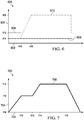
- Chart 700 is an illustrative example of temperatures of thermoset composite charge 104 during forming and curing in induction system 102 of Figure 1 .
- Chart 700 is an illustrative example of temperatures of a thermoset composite charge 202 during forming and curing in induction system 206 of Figure 2 .
- Chart 700 is an illustrative example of temperatures of thermoset composite charge 302 during forming and curing in induction system 300 of Figure 3 .
- Chart 700 is an illustrative example of temperatures of thermoset composite charge 402 during forming and curing in induction system 400 of Figure 4 .
- Chart 700 is an illustrative example of temperatures of thermoset composite charge 502 during forming and curing in induction system 500 of Figure 5 .
- Chart 700 is an illustrative example of temperatures of a thermoset composite charge formed and cured using the pressures shown in chart 600 of Figure 6 .
- Chart 700 has x-axis 702 and y-axis 704.
- X-axis 702 is a representation of time.
- Y-axis 704 is a representation of temperature.
- Line 706 is representative of a temperature of a thermoset composite charge between a flexible membrane and a vacuum film in an induction system.
- Line 706 starts at temperature 708 and heats to temperature 710 by time 616.
- Increasing the temperature of a thermoset composite charge represented by line 706 is performed by heating a second smart susceptor material within a die cavity of the induction system.
- the second smart susceptor material has a second Curie temperature and is configured to heat the thermoset composite charge to temperature 710.
- a first smart susceptor material having a first Curie temperature higher than the second Curie temperature may be used to heat the die cavity of the induction system.
- the first smart susceptor material is heated to a temperature below the forming temperature. Heating the die cavity using the first smart susceptor material aids in heating the entirety of the thermoset composite charge to the forming temperature.
- Forming of the thermoset composite charge by application of pressure begins at time 616. Forming takes place from time 616 to time 618. The application of pressure during forming can be seen in Figure 6 between time 616 and time 618. During forming, line 706 maintains temperature 710 from time 616 to time 618. Temperature 710 may be referred to as a forming temperature.
- thermoset composite charge has been shaped to the first smart susceptor material.
- thermoset composite charge has been shaped to the first smart susceptor material.
- line 706 starts at temperature 710 and heats to temperature 712 by time 714. Increasing the temperature of a thermoset composite charge represented by line 706 is performed by heating the first smart susceptor material.
- Temperature 712 is a curing temperature for the thermoset composite charge.
- Line 706 is maintained at temperature 712 from time 714 to time 716.
- Line 706 is maintained at temperature 712 using the first smart susceptor material.
- a cooling system is used to cool the first smart susceptor material if the first smart susceptor material exceeds a Curie temperature of the first smart susceptor material.
- exothermic reactions of the thermoset composite charge cause the first smart susceptor material to locally exceed the Curie temperature.
- a combination of heating using the first smart susceptor material and cooling using the cooling system is used to maintain line 706 at temperature 712.
- thermoset composite charge is cured from time 714 to 716.
- a controlled cooldown of the thermoset composite charge begins.
- line 706 decreases in temperature from temperature 712 to temperature 708.
- the controlled cooldown includes the application of both heat and cooling to the thermoset composite charge.
- the controlled cooldown includes simultaneously cooling the first smart susceptor surface and applying heat using a conformable smart susceptor blanket.
- Method 800 may be used to form and cure thermoset composite charge 104 using induction system 102 of Figure 1 .
- Method 800 may be used to form and cure thermoset composite charge 202 using induction system 206 of Figure 2 .
- Method 800 may be used to form and cure thermoset composite charge 302 using induction system 300 of Figure 3 .
- Method 800 may be used to form and cure thermoset composite charge 402 using induction system 400 of Figure 4 .
- Method 800 may be used to form and cure thermoset composite charge 502 using induction system 500 of Figure 5 .
- Method 800 places a thermoset composite charge within a die cavity of an induction tool, wherein the induction tool comprises a first tooling die and a second tooling die movable with respect to each other, and wherein the first tooling die and the second tooling die form the die cavity, the first tooling die and the second tooling die comprising a plurality of stacked metal sheets, a plurality of air gaps defined between adjacent stacked metal sheets (operation 802 ).
- Method 800 heats the thermoset composite charge within the die cavity to a forming temperature using a second smart susceptor material within the die cavity (operation 804 ).
- the second smart susceptor material is a component of any desirable structure.
- the second smart susceptor material is a component of a conformable smart susceptor blanket. In other illustrative examples, the second smart susceptor material is part of a smart susceptor plate. In one illustrative example, the second smart susceptor material is part of a smart susceptor plate with smart susceptor circuits.
- heating the thermoset composite charge to the forming temperature comprises heating the thermoset composite charge using a conformable smart susceptor blanket positioned within the die cavity, wherein the conformable smart susceptor blanket comprises the second smart susceptor material.
- heating the thermoset composite charge within the die cavity to the forming temperature using the second smart susceptor material comprises heating a first side of the thermoset composite charge using the second smart susceptor material, and heating the die cavity using the first smart susceptor surface.
- heating the thermoset composite charge to the forming temperature comprises generating a second frequency range using a second set of conductors in the conformable smart susceptor blanket.
- Method 800 moves the thermoset composite charge within the die cavity towards a first smart susceptor surface connected to the first tooling die after heating the thermoset composite charge to the forming temperature (operation 806 ).
- Method 800 moves the thermoset composite charge using a flexible membrane.
- a conformable smart susceptor blanket comprises the flexible membrane.
- moving the thermoset composite charge within the die cavity comprises increasing a pressure between the conformable smart susceptor blanket and a second smart susceptor surface connected to the second tooling die, wherein the conformable smart susceptor blanket comprises the flexible membrane.
- Method 800 applies pressure to the thermoset composite charge using a flexible membrane to conform the thermoset composite charge to the first smart susceptor surface (operation 808 ). Method 800 heats the thermoset composite charge to a curing temperature using the first smart susceptor surface (operation 810 ). Afterwards, the method terminates.
- heating the thermoset composite charge to the curing temperature comprises generating a first frequency range using a first plurality of conductors, wherein the first smart susceptor material is configured to be heated by the first frequency range.
- each block in the flowcharts or block diagrams may represent a module, a segment, a function, and/or a portion of an operation or step.
- the function or functions noted in the blocks may occur out of the order noted in the figures.
- two blocks shown in succession may be executed substantially concurrently, or the blocks may sometimes be performed in the reverse order, depending upon the functionality involved.
- other blocks may be added, in addition to the illustrated blocks, in a flowchart or block diagram.
- method 800 further comprises cooling portions of the first smart susceptor surface to below a first Curie temperature of the first smart susceptor surface. In some illustrative examples, method 800 further comprises cooling the thermoset composite charge in a controlled fashion by simultaneously cooling the first smart susceptor surface using cooling medium flowing through the plurality of air gaps of the first tooling die and applying heat from the conformable smart susceptor blanket.
- aircraft manufacturing and service method 900 may be described in the context of aircraft manufacturing and service method 900 as shown in Figure 9 and aircraft 1000 as shown in Figure 10 .
- Figure 9 an illustration of an aircraft manufacturing and service method is depicted in accordance with an illustrative embodiment.
- aircraft manufacturing and service method 900 may include specification and design 902 of aircraft 1000 in Figure 10 and material procurement 904.
- aircraft 1000 During production, component and subassembly manufacturing 906 and system integration 908 of aircraft 1000 takes place. Thereafter, aircraft 1000 may go through certification and delivery 910 in order to be placed in service 912. While in service 912 by a customer, aircraft 1000 is scheduled for routine maintenance and service 914, which may include modification, reconfiguration, refurbishment, or other maintenance and service.
- Each of the processes of aircraft manufacturing and service method 900 may be performed or carried out by a system integrator, a third party, and/or an operator.
- the operator may be a customer.
- a system integrator may include, without limitation, any number of aircraft manufacturers and major-system subcontractors
- a third party may include, without limitation, any number of vendors, subcontractors, and suppliers
- an operator may be an airline, a leasing company, a military entity, a service organization, and so on.
- aircraft 1000 is produced by aircraft manufacturing and service method 900 of Figure 9 and may include airframe 1002 with plurality of systems 1004 and interior 1006.
- systems 1004 include one or more of propulsion system 1008, electrical system 1010, hydraulic system 1012, and environmental system 1014. Any number of other systems may be included.
- propulsion system 1008 electrical system 1010, hydraulic system 1012, and environmental system 1014. Any number of other systems may be included.
- an aerospace example is shown, different illustrative embodiments may be applied to other industries, such as the automotive industry.
- Apparatuses and methods embodied herein may be employed during at least one of the stages of aircraft manufacturing and service method 900.
- One or more illustrative embodiments may be used during at least one of component and subassembly manufacturing 906, system integration 908, or maintenance and service 914 of Figure 9 .
- induction system 102 of Figure 1 may be used during component and subassembly manufacturing 906 to form and cure thermoset composite charge 104.
- Thermoset composite charge 104 of Figure 1 may be formed and cured during component and subassembly manufacturing 906 using method 800 of Figure 8 .
- the phrase "at least one of,” when used with a list of items, means different combinations of one or more of the listed items may be used, and only one of each item in the list may be needed. In other words, “at least one of” means any combination of items and number of items may be used from the list, but not all of the items in the list are required.
- the item may be a particular object, a thing, or a category.
- “at least one of item A, item B, or item C” may include, without limitation, item A, item A and item B, or item B. This example also may include item A, item B, and item C, or item B and item C. Of course, any combination of these items may be present. In other examples, "at least one of” may be, for example, without limitation, two of item A, one of item B, and ten of item C; four of item B and seven of item C; or other suitable combinations.
- Thermoset composite charge 106 of Figure 1 may be a formed and cured into a component of aircraft 1000 joined during system integration 908.
- Induction system 102 of Figure 1 may be used to form replacement components used during maintenance and service 914 of Figure 9 .
- induction system 102 of Figure 1 may be used to create composite structure from thermoset composite charge 104 to form a replacement component used during maintenance and service 914 of Figure 9 .
- Thermoset composite charge 104 of Figure 1 may be formed and cured into a component for at least one of airframe 1002 or interior 1006.
- the illustrative examples provide a first smart susceptor material and a second smart susceptor material to form and cure a thermoset composite charge in an induction system.
- Both forming and curing in a single induction system may reduce at least one of overall tooling costs, tooling footprint, manufacturing time, manufacturing utilities, or manufacturing waste.
- forming and curing using induction heating may use less energy than curing in an autoclave.
- forming and curing using a single induction system may reduce material waste from bagging and rebagging a thermoset composite charge for separate forming and curing steps.
- the induction system combines the use of a flexible smart susceptor blanket style heater with an inductively heated laminated tool using smart susceptor shells.
- the conformable smart susceptor blanket is heated to the optimal forming temperature and the lay-up is formed against the surface of the laminated tool using pneumatic pressure against a flexible membrane.
- the conformable smart susceptor blanket is the flexible membrane.
- a separate flexible membrane is provided for applying pneumatic pressure.
- the laminated tooling is then rapidly heated to the curing temperature and the charge is cured.
- This process enables the forming of initial flat or simply shaped charges into more complicated cure parts in a seamlessly combined forming and curing step.
- This process uses the quick lay-up of simple shapes along with the efficient and rapid forming and curing using less labor for improved affordability.
Abstract
Description
- The present disclosure relates generally to induction tooling, and more specifically, to induction tooling for performing manufacturing operations on thermoset composite charges. Yet more specifically, the present disclosure relates to an induction system configured to both form and cure a thermoset composite charge.
- Composite materials are tough, light-weight materials created by combining two or more functional components. For example, a composite material may include reinforcing fibers bound in a polymer resin matrix. The fibers may be unidirectional or may take the form of a woven cloth or fabric. The fibers and resin are arranged and cured to form a composite material.
- Thermoset composite materials are composite materials having a resin that cures upon application of at least one of temperature or pressure, thus forming the final composite structure. Thermoset composite materials are shaped prior to curing.
- In manufacturing composite structures, layers of composite material are laid up. The layers may be comprised of fibers in sheets. These sheets may take the form of fabrics, tape, tows, or other suitable forms. In some cases, resin may be infused or pre-impregnated into the sheets. These types of sheets are commonly referred to as prepreg.
- In some examples, thermoset composite structures with complex cross-sections are formed by laying up the complex cross-section layer by layer by hand or using automated lamination equipment such as a tape laminating machine or a fiber placement system. However, laying up complex cross-sections layer by layer may take an undesirable amount of time. Laying up complex cross-sections layer by layer may impact at least one of the amount of manufacturing time for a component, the amount of in-process flow time for a layup tool, or the amount of human operator time.
- Thermoset composite structures with complex cross-sections may be created by forming thermoset composite charges. A thermoset composite charge has multiple layers of thermoset prepreg laid up substantially flat. A thermoset composite charge may be laid up flat by a tape laminating machine.
- After laying up a thermoset composite charge, the thermoset composite charge may be drape-formed to a complex cross-section. Drape forming uses a forming tool operating at a forming temperature. After drape forming, the formed thermoset composite charge is transferred to a cure tool, such as an autoclave. Separate forming and curing steps may impact overall manufacturing time by adding transfer processes. Additionally, separate forming and curing steps use separate forming and curing tooling.
- Therefore, it would be desirable to have a method and apparatus that take into account at least some of the issues discussed above, as well as other possible issues. For example, it may be desirable to provide an apparatus and method for forming thermosets with complex cross-sections with at least one of reduced manufacturing time, reduced manufacturing costs, or reduced utilities. As another example, it may be desirable to provide an apparatus for both forming and curing a thermoset composite charge.
- An illustrative embodiment of the present disclosure provides an induction system configured to provide temperature and pressure control for forming and curing of a thermoset composite charge. The induction system comprises a first tooling die and a second tooling die, a first smart susceptor material, a second smart susceptor material, and a flexible membrane. The first tooling die and the second tooling die are movable with respect to each other. The first tooling die and the second tooling die form a die cavity. The first tooling die and the second tooling die comprise a plurality of stacked metal sheets. A plurality of air gaps is defined between adjacent stacked metal sheets. The first smart susceptor material is within the die cavity and connected to the first tooling die. The first smart susceptor material has a first Curie temperature. The second smart susceptor material is within the die cavity and associated with the second tooling die. The second smart susceptor material has a second Curie temperature lower than the first Curie temperature. The flexible membrane is between the second tooling die and the first smart susceptor material. The flexible membrane is configured to receive pressure.
- Another illustrative embodiment of the present disclosure provides an induction system configured to provide temperature and pressure control for forming and curing of a thermoset composite charge. The induction system comprises an induction tool and a conformable smart susceptor blanket positioned within a die cavity of the induction tool. The induction tool comprises a first tooling die and a second tooling die, a first set of conductors, a first smart susceptor surface, and a second smart susceptor surface. The first tooling die and the second tooling die are movable with respect to each other. The first tooling die and the second tooling die comprise a plurality of stacked metal sheets. A plurality of air gaps is defined between adjacent stacked metal sheets. The first smart susceptor surface is connected to the first tooling die. The second smart susceptor surface is connected to the second tooling die.
- A further illustrative embodiment of the present disclosure provides a method. A thermoset composite charge is placed within a die cavity of an induction tool, wherein the induction tool comprises a first tooling die and a second tooling die movable with respect to each other, wherein the first tooling die and the second tooling die form the die cavity, the first tooling die and the second tooling die comprising a plurality of stacked metal sheets, a plurality of air gaps defined between adjacent stacked metal sheets. The thermoset composite charge within the die cavity is heated to a forming temperature using a second smart susceptor material within the die cavity. The thermoset composite charge within the die cavity is moved towards a first smart susceptor surface connected to the first tooling die after heating the thermoset composite charge to the forming temperature. Pressure is applied to the thermoset composite charge using a flexible membrane to conform the thermoset composite charge to the first smart susceptor surface. The thermoset composite charge is heated to a curing temperature using the first smart susceptor surface.
- The features and functions can be achieved independently in various embodiments of the present disclosure or may be combined in yet other embodiments in which further details can be seen with reference to the following description and drawings.
- The novel features believed characteristic of the illustrative embodiments are set forth in the appended claims. The illustrative embodiments, however, as well as a preferred mode of use, further objectives and features thereof, will best be understood by reference to the following detailed description of an illustrative embodiment of the present disclosure when read in conjunction with the accompanying drawings, wherein:
-
Figure 1 is an illustration of a block diagram of a manufacturing environment in accordance with an illustrative embodiment; -
Figure 2 is an illustration of an isometric view of a manufacturing environment with an induction system for forming and curing thermoset composite charges in accordance with an illustrative embodiment; -
Figure 3 is an illustration of a cross-sectional view of an induction system for forming and curing thermoset composite charges in accordance with an illustrative embodiment; -
Figure 4 is an illustration of a cross-sectional view of an induction system for forming and curing thermoset composite charges in accordance with an illustrative embodiment; -
Figure 5 is an illustration of a cross-sectional view of an induction system for forming and curing thermoset composite charges in accordance with an illustrative embodiment; -
Figure 6 is an illustration of a pressure versus time chart of forming and curing a thermoset composite charge in an induction system in accordance with an illustrative embodiment; -
Figure 7 is an illustration of a temperature versus time chart of forming and curing a thermoset composite charge in an induction system in accordance with an illustrative embodiment; -
Figure 8 is an illustration of a flowchart of a process for forming and curing a thermoset composite charge in accordance with an illustrative embodiment; -
Figure 9 is an illustration of an aircraft manufacturing and service method in the form of a block diagram in accordance with an illustrative embodiment; and -
Figure 10 is an illustration of an aircraft in the form of a block diagram in which an illustrative embodiment may be implemented. - The illustrative embodiments recognize and take into account one or more different considerations. For example, the illustrative embodiments recognize and take into account that current processing systems for complex small thermoset components require undesirable amounts of labor for hand lay-up and curing. The illustrative embodiments recognize and take into account that heated presses/ovens operating at separate temperatures for forming and curing requires multiple set-ups and processing runs.
- Referring now to the figures and, in particular, with reference to
Figure 1 , an illustration of a block diagram of a manufacturing environment is depicted in accordance with an illustrative embodiment. -
Manufacturing environment 100 includesinduction system 102 for forming and curing thermosetcomposite charge 104.Induction system 102 is configured to provide temperature and pressure control for forming and curing of thermosetcomposite charge 104. - In one illustrative example,
induction system 102 comprisesinduction tool 106 and conformablesmart susceptor blanket 108 positioned withindie cavity 110 ofinduction tool 106.Induction tool 106 comprises first tooling die 112, second tooling die 114, first set ofconductors 116, firstsmart susceptor surface 118, and secondsmart susceptor surface 120. First tooling die 112 and second tooling die 114 are movable with respect to each other. First tooling die 112 and second tooling die 114 comprise a plurality of stacked metal sheets. A plurality of air gaps is defined between the adjacent stacked metal sheets. - First tooling die 112 comprises plurality of
stacked metal sheets 122. Plurality ofair gaps 124 are defined between adjacent stacked metal sheets of plurality ofstacked metal sheets 122. - Second tooling die 114 comprises plurality of
stacked metal sheets 126. Plurality ofair gaps 128 are defined between adjacent stacked metal sheets of plurality ofstacked metal sheets 126. - First
smart susceptor material 130 of firstsmart susceptor surface 118 and secondsmart susceptor surface 120 has a higher Curie temperature than secondsmart susceptor material 132 in conformablesmart susceptor blanket 108.First Curie temperature 134 of firstsmart susceptor material 130 is higher thansecond Curie temperature 136 of secondsmart susceptor material 132. - Conformable
smart susceptor blanket 108 comprises second set ofconductors 138 configured to generatesecond frequency range 140. In some illustrative examples,second frequency range 140 is 100 kHz-400 kHz. In some illustrative examples, second set ofconductors 138 is situated to generate a magnetic field cancels out over a short distance. In these illustrative examples, second set ofconductors 138 generatingsecond frequency range 140 will not appreciably affect firstsmart susceptor surface 118 and secondsmart susceptor surface 120. - In some illustrative examples,
second frequency range 140 andfirst frequency range 142 of first set ofconductors 116 may have overlapping frequencies. In these illustrative examples,second Curie temperature 136 of secondsmart susceptor material 132 protects secondsmart susceptor material 132 from overheating. - In some illustrative examples,
second frequency range 140 is separate fromfirst frequency range 142 of first set ofconductors 116.First frequency range 142 andsecond frequency range 140 may be separated by a gap. In some illustrative examples,first frequency range 142 may be 120 Hz-1300 Hz whilesecond frequency range 140 is 100 kHz-400 kHz. - In some illustrative examples, second set of
conductors 138 are oriented at different angles than first set ofconductors 116. In some illustrative examples, second set ofconductors 138 are oriented at 90 degrees (orthogonal) relative to first set ofconductors 116. In some illustrative examples, second set ofconductors 138 are oriented at 90 degrees (orthogonal) relative to first set ofconductors 116 and used at a different frequency. In some illustrative examples, the difference in orientation of a magnetic field of second set ofconductors 138 and a magnetic field of first set ofconductors 116 allows second set ofconductors 138 to couple well with secondsmart susceptor material 132, but leave firstsmart susceptor material 130 relatively alone. In some illustrative examples, the difference in orientation of a magnetic field of second set ofconductors 138 and a magnetic field of first set ofconductors 116 along with the difference in frequency betweenfirst frequency range 142 andsecond frequency range 140 allows second set ofconductors 138 to couple well with secondsmart susceptor material 132, but leave firstsmart susceptor material 130 relatively alone. - In these illustrative examples,
induction system 102 hasfirst pressure region 144,second pressure region 146, andthird pressure region 148.First pressure region 144 is formed by firstsmart susceptor surface 118 and vacuum film 150.Second pressure region 146 is formed by vacuum film 150 and conformablesmart susceptor blanket 108.Third pressure region 148 is formed by conformablesmart susceptor blanket 108 and secondsmart susceptor surface 120. - Each of
first pressure region 144,second pressure region 146, andthird pressure region 148 has an independently controlled pressure.First pressure region 144,second pressure region 146, andthird pressure region 148 are controlled to apply desirable pressures to form and then cure thermosetcomposite charge 104 positioned between vacuum film 150 and conformablesmart susceptor blanket 108. Although each offirst pressure region 144,second pressure region 146, andthird pressure region 148 is independently controlled, each offirst pressure region 144,second pressure region 146, andthird pressure region 148 is controlled in concert to form and cure thermosetcomposite charge 104. - For example,
first pressure region 144 is held at a higher pressure thansecond pressure region 146 andthird pressure region 148 during heating of thermosetcomposite charge 104 to a forming temperature. As another example, the pressure ofthird pressure region 148 is increased to greater thanfirst pressure region 144 andsecond pressure region 146 to form thermosetcomposite charge 104 against firstsmart susceptor surface 118. To form thermosetcomposite charge 104, the pressure infirst pressure region 144 is reduced. During curing of thermosetcomposite charge 104, pressure inthird pressure region 148 is greater than the pressures infirst pressure region 144 andsecond pressure region 146. - In some illustrative examples,
induction system 102 includescooling system 152.Cooling system 152 is configured to provide cooling medium 154 to a first set of the stacked metal sheets such that the cooling medium passes through the air gaps between the first set of stacked metal sheets. For example,cooling system 152 is configured to provide cooling medium 154 to plurality ofstacked metal sheets 122 such that cooling medium 154 passes through plurality ofair gaps 124 of plurality ofstacked metal sheets 122. In some illustrative examples,cooling system 152 may be used to provide cooling medium 154 to a subset of plurality ofair gaps 124. By controlling the application of cooling medium 154,cooling system 152 may be used to provide directed cooling to selected portions of firstsmart susceptor surface 118. - In some illustrative examples,
cooling system 152 is configured to provide cooling medium 154 to plurality ofstacked metal sheets 126 such that cooling medium 154 passes through plurality ofair gaps 128 of plurality ofstacked metal sheets 126. In some illustrative examples,cooling system 152 may be used to provide cooling medium 154 to a subset of plurality ofair gaps 128. By controlling the application of cooling medium 154,cooling system 152 may be used to provide directed cooling to selected portions of secondsmart susceptor surface 120. - In some illustrative examples,
induction system 102 comprises first tooling die 112 and second tooling die 114, firstsmart susceptor material 130, secondsmart susceptor material 132, andflexible membrane 155. In these illustrative examples, first tooling die 112 and second tooling die 114 are movable with respect to each other. First tooling die 112 and second tooling die 114 form diecavity 110. First tooling die 112 and second tooling die 114 comprise a plurality of stacked metal sheets, and a plurality of air gaps defined between adjacent stacked metal sheets. - First
smart susceptor material 130 is withindie cavity 110 and connected to first tooling die 112. Firstsmart susceptor material 130 hasfirst Curie temperature 134. - Second
smart susceptor material 132 is withindie cavity 110 and associated with second tooling die 114. Secondsmart susceptor material 132 hassecond Curie temperature 136 lower thanfirst Curie temperature 134. -
Flexible membrane 155 is between second tooling die 114 and firstsmart susceptor material 130.Flexible membrane 155 is configured to receive pressure. More specifically,flexible membrane 155 is configured to receive pressure to form thermosetcomposite charge 104 against firstsmart susceptor surface 118. -
Induction system 102 hasfirst pressure region 144,second pressure region 146, andthird pressure region 148.First pressure region 144 is withindie cavity 110 and is formed by firstsmart susceptor material 130 and vacuum film 150.Second pressure region 146 is within thedie cavity 110 and is formed by vacuum film 150 andflexible membrane 155.Third pressure region 148 is withindie cavity 110 and is formed byflexible membrane 155 andtooling surface 162 connected to second tooling die 114. -
Induction system 102 comprises first set ofconductors 116 and second set ofconductors 138. First set ofconductors 116 generatesfirst frequency range 142. Firstsmart susceptor material 130 is configured to be heated byfirst frequency range 142. In some illustrative examples, first set ofconductors 116 is a first set of induction coils extending through first tooling die 112 and second tooling die 114. In other illustrative examples, first set ofconductors 116 could be a number of large beds placed insidedie cavity 110 ofinduction tool 106. It is more energy efficient to have first set ofconductors 116 closer to firstsmart susceptor surface 118 and secondsmart susceptor surface 120. When first set ofconductors 116 is a number of large beds, it may be possible to remove first set ofconductors 116 and place them into a different induction tool other thaninduction tool 106. - Second set of
conductors 138 generatessecond frequency range 140. Secondsmart susceptor material 132 is configured to be heated bysecond frequency range 140. In some illustrative examples, when secondsmart susceptor material 132 is part of conformablesmart susceptor blanket 108, second set ofconductors 138 may take the form of conductive threads. In some illustrative examples, second set ofconductors 138 may be a second plurality of induction coils. In some illustrative examples, second set ofconductors 138 may be incorporated intoflexible membrane 155. In some illustrative examples, conformablesmart susceptor blanket 108 includes secondsmart susceptor material 132 wrapped in a spiral around second set ofconductors 138 in the form of a litz wire. In these illustrative examples, the material and pattern of second set ofconductors 138 and secondsmart susceptor material 132 affects the flexibility of conformablesmart susceptor blanket 108. In these illustrative examples, the material and pattern of second set ofconductors 138 and secondsmart susceptor material 132 affects the degree to which conformablesmart susceptor blanket 108 stretches. - Second
smart susceptor material 132 can be incorporated into any desirable format. In some illustrative examples, secondsmart susceptor material 132 is a component of conformablesmart susceptor blanket 108 positioned withindie cavity 110. In some illustrative examples, conformablesmart susceptor blanket 108 further comprisesflexible membrane 155. When conformablesmart susceptor blanket 108 comprisesflexible membrane 155, pressure is applied to conformablesmart susceptor blanket 108 to form thermosetcomposite charge 104 to firstsmart susceptor surface 118. - In some other illustrative examples, second
smart susceptor material 132 issmart susceptor plate 156 beneathflexible membrane 155. In these illustrative examples,smart susceptor plate 156 is used to heat thermosetcomposite charge 104 prior to forming thermosetcomposite charge 104 to firstsmart susceptor surface 118 using separateflexible membrane 155. - In some illustrative examples, first
smart susceptor material 130 is part oftooling surface 158 withsmart susceptor circuits 160 embedded intooling surface 158.Tooling surface 158 is connected to first tooling die 112.Tooling surface 158 may also be referred to as a first tooling surface. In some illustrative examples, firstsmart susceptor material 130 is part oftooling surface 162 withsmart susceptor circuits 164 embedded intooling surface 162.Tooling surface 162 is connected to second tooling die 114.Tooling surface 162 may also be referred to as a second tooling surface. - In some illustrative examples,
smart susceptor circuits 160 andsmart susceptor circuits 164 include firstsmart susceptor material 130 and first set ofconductors 116. In some illustrative examples,smart susceptor circuits 160 andsmart susceptor circuits 164 include only firstsmart susceptor material 130. - As depicted, first
smart susceptor material 130 connected to first tooling die 112 is part of a first tooling surface,tooling surface 158, connected to first tooling die 112. A second tooling surface,tooling surface 162, is connected to second tooling die 114. The second tooling surface,tooling surface 162, comprises firstsmart susceptor material 130. - First
smart susceptor material 130 and secondsmart susceptor material 132 are used to heat thermosetcomposite charge 104. First, at least one of firstsmart susceptor material 130 or secondsmart susceptor material 132 are used to heat thermosetcomposite charge 104 to a forming temperature. - In some illustrative examples, second
smart susceptor material 132 is used to heat thermosetcomposite charge 104 to a forming temperature. In some illustrative examples, both firstsmart susceptor material 130 and secondsmart susceptor material 132 are used to heat thermosetcomposite charge 104. In some illustrative examples, secondsmart susceptor material 132 is used to heat at least a portion of thermosetcomposite charge 104 while firstsmart susceptor material 130 is used to heatdie cavity 110. In some illustrative examples, secondsmart susceptor material 132 is used to heatfirst side 166 of thermosetcomposite charge 104 that faces the secondsmart susceptor material 132 while firstsmart susceptor material 130 is used to heatdie cavity 110. - After heating thermoset
composite charge 104 to a forming temperature, thermosetcomposite charge 104 is moved towards firstsmart susceptor material 130. Firstsmart susceptor material 130 is used to heat thermosetcomposite charge 104 to a curing temperature. Thermosetcomposite charge 104 is held at the curing temperature for a desired period of time. At least one of firstsmart susceptor material 130 orcooling system 152 are used to maintain thermosetcomposite charge 104 at the curing temperature. Afterwards, at least one of firstsmart susceptor material 130, secondsmart susceptor material 132, orcooling system 152 are used to cool thermosetcomposite charge 104 in a controlled fashion. - The illustration of
manufacturing environment 100 inFigure 1 is not meant to imply physical or architectural limitations to the manner in which an illustrative embodiment may be implemented. Other components in addition to or in place of the ones illustrated may be used. Some components may be unnecessary. Also, the blocks are presented to illustrate some functional components. One or more of these blocks may be combined, divided, or combined and divided into different blocks when implemented in an illustrative embodiment. - For example, in some illustrative examples, second
smart susceptor material 132 is present inflexible membrane 155 while second set ofconductors 138 is outside offlexible membrane 155. When second set ofconductors 138 is present outside offlexible membrane 155,flexible membrane 155 may have increased flexibility. In some illustrative examples, when second set ofconductors 138 is outside offlexible membrane 155, secondsmart susceptor material 132 is discontinuous withinflexible membrane 155. Having secondsmart susceptor material 132 discontinuous with flexible membrane may increase the flexibility offlexible membrane 155. - When the second set of
conductors 138 is outside offlexible membrane 155, firstsmart susceptor material 130 and secondsmart susceptor material 132 operate independently due to at least one of design of second set ofconductors 138 or shape of secondsmart susceptor material 132. In some illustrative examples, the skin effect may be used to selectively heat large susceptors over small susceptors. In some illustrative examples in which secondsmart susceptor material 132 is small, whenfirst frequency range 142 is a low frequency (120-3,000 Hz), first set ofconductors 116 would not couple well with secondsmart susceptor material 132. In these illustrative examples, the magnetic field from first set ofconductors 116 would selectively couple with firstsmart susceptor material 130. Whensecond frequency range 140 for second set ofconductors 138 is a high frequency (100-400 kHz), secondsmart susceptor material 132 will couple. In some of these illustrative examples, firstsmart susceptor material 130 may also couple tosecond frequency range 140. At least one of geometry of secondsmart susceptor material 132 or wave guides may be used to selectively couple second set ofconductors 138 to secondsmart susceptor material 132. - In some illustrative examples, geometry of second
smart susceptor material 132 is used to selectively heat small susceptors over large susceptors. For example, second set ofconductors 138 may be arranged to concentrate a magnetic field from second set ofconductors 138 intoflexible membrane 155 using at least one of geometry or wave guides. In some illustrative examples, secondsmart susceptor material 132 may be shaped to couple with a magnetic field generated by second set ofconductors 138. - Turning now to
Figure 2 , an illustration of an isometric view of a manufacturing environment with an induction system for forming and curing thermoset composite charges is depicted in accordance with an illustrative embodiment.Manufacturing environment 200 is a physical implementation ofmanufacturing environment 100 ofFigure 1 . - Thermoset
composite charge 202 is present onlayup tool 204 inmanufacturing environment 200. As depicted, thermosetcomposite charge 202 is substantially flat. -
Layup tool 204 may be one of a plurality of layup tools for thermoset composite charges. When a plurality of layup tools is present, a plurality of thermoset composite charges may be laid up substantially simultaneously. Laying up thermosetcomposite charge 202 onlayup tool 204 may take less time than laying up a thermoset composite structure with a complex cross-section on a complex layup mandrel. -
Induction system 206 is present inmanufacturing environment 200.Induction system 206 is a physical implementation ofinduction system 102 ofFigure 1 .Induction system 206 is configured to both form and cure thermosetcomposite charge 202. - Thermoset
composite charge 202 is placed into a die cavity ofinduction system 206.Induction system 206 forms and then cures thermosetcomposite charge 202. Afterwards, a cured thermoset composite structure with a complex cross-section is removed frominduction system 206. -
Induction system 206 may have a smaller footprint than separate forming and curing tools. In some illustrative examples,induction system 206 may be smaller than an autoclave. In some illustrative examples,induction system 206 reduces the footprint ofmanufacturing environment 200 dedicated to manufacturing a thermoset composite structure with a complex cross-section. - In some illustrative examples, operating
induction system 206 may take fewer resources than an autoclave. In some illustrative examples, operatinginduction system 206 may take less processing time than operating an autoclave. - Turning now to
Figure 3 , an illustration of a cross-sectional view of an induction system for forming and curing thermoset composite charges is depicted in accordance with an illustrative embodiment.Induction system 300 is a physical implementation ofinduction system 102 ofFigure 1 .Induction system 300 may be an implementation ofinduction system 206 ofFigure 2 . -
Induction system 300 is configured to provide temperature and pressure control for forming and curing of thermosetcomposite charge 302.Induction system 300 comprisesinduction tool 304 and conformablesmart susceptor blanket 306. -
Induction tool 304 comprises first tooling die 308 and second tooling die 310, first set ofconductors 312, firstsmart susceptor surface 314, and secondsmart susceptor surface 316. First tooling die 308 and second tooling die 310 are movable with respect to each other. First tooling die 308 and second tooling die 310 comprise a plurality of stacked metal sheets, and a plurality of air gaps defined between adjacent stacked metal sheets. - First tooling die 308 comprises plurality of
stacked metal sheets 318. Plurality ofair gaps 320 is defined between adjacent stacked metal sheets of plurality ofstacked metal sheets 318. - Second tooling die 310 comprises plurality of
stacked metal sheets 322. Plurality ofair gaps 324 is defined between adjacent stacked metal sheets of plurality ofstacked metal sheets 322. - First set of
conductors 312 is configured to generate a first frequency range. The first frequency range causes firstsmart susceptor material 325 to generate heat. As depicted, first set ofconductors 312 takes the form of first set ofinduction coils 323 extending through first tooling die 308 and second tooling die 310. - First
smart susceptor surface 314 is connected to first tooling die 308. Firstsmart susceptor surface 314 is formed of firstsmart susceptor material 325. Secondsmart susceptor surface 316 is connected to second tooling die 310. Secondsmart susceptor surface 316 is formed of firstsmart susceptor material 325. - Conformable
smart susceptor blanket 306 is positioned withindie cavity 326 ofinduction tool 304. Conformablesmart susceptor blanket 306 includes secondsmart susceptor material 328.First side 329 of thermosetcomposite charge 302 faces secondsmart susceptor material 328. Firstsmart susceptor material 325 has a higher Curie temperature than secondsmart susceptor material 328. - The forming temperature of thermoset
composite charge 302 is lower than the curing temperature of thermosetcomposite charge 302. Having two smart susceptor materials with two different Curie temperatures allows for controlled application of heat to thermosetcomposite charge 302 at two different temperatures. Secondsmart susceptor material 328 is used to control heating of thermosetcomposite charge 302 to the forming temperature. The second Curie temperature allows for controlled heating to the forming temperature. - First
smart susceptor material 325 is used to control heating of thermosetcomposite charge 302 to the curing temperature. The first Curie temperature allows for controlled heating to the curing temperature. - Conformable
smart susceptor blanket 306 also has second set ofconductors 330. Second set ofconductors 330 are configured to generate a second frequency range separate from the first frequency range of first set ofconductors 312. - To form thermoset
composite charge 302,induction system 300 heats thermosetcomposite charge 302 to a forming temperature. In some illustrative examples, conformablesmart susceptor blanket 306 heats thermosetcomposite charge 302 to the forming temperature. In some illustrative examples, firstsmart susceptor surface 314 and secondsmart susceptor surface 316 are used to heatdie cavity 326 in addition to conformablesmart susceptor blanket 306 heating thermosetcomposite charge 302. In these illustrative examples, firstsmart susceptor surface 314 and secondsmart susceptor surface 316 may be heated to a temperature below the forming temperature. - To cure thermoset
composite charge 302,induction system 300 heats thermosetcomposite charge 302 to a curing temperature. In some illustrative examples, firstsmart susceptor surface 314 heats thermosetcomposite charge 302 to the curing temperature. In some illustrative examples, firstsmart susceptor surface 314 heats thermosetcomposite charge 302 while cooling system 331 simultaneously cools portions of firstsmart susceptor surface 314. For example, thermosetcomposite charge 302 may have exothermic curing reactions. The exothermic reactions during curing may heat firstsmart susceptor surface 314 past the first Curie temperature. Cooling system 331 may cool firstsmart susceptor surface 314 to below the first Curie temperature. -
Induction system 300 hasfirst pressure region 332,second pressure region 334, andthird pressure region 336.First pressure region 332 is formed by firstsmart susceptor surface 314 andvacuum film 338.Second pressure region 334 is formed byvacuum film 338 and conformablesmart susceptor blanket 306. Thermosetcomposite charge 302 is positioned betweenvacuum film 338 and conformablesmart susceptor blanket 306.Third pressure region 336 is formed by conformablesmart susceptor blanket 306 and secondsmart susceptor surface 316. - Conformable
smart susceptor blanket 306 acts as a flexible membrane. When an increased pressure is introduced tothird pressure region 336, conformablesmart susceptor blanket 306 applies pressure to thermosetcomposite charge 302 to form thermosetcomposite charge 302 against firstsmart susceptor surface 314. - Each of
first pressure region 332,second pressure region 334, andthird pressure region 336 are individually controlled to form and cure thermosetcomposite charge 302.First pressure region 332,second pressure region 334, andthird pressure region 336 work in concert to form and cure thermosetcomposite charge 302. - The illustration of
induction system 300 inFigure 3 is not meant to imply architectural limitations as to the manner in which different illustrative embodiments may be implemented. For example, firstsmart susceptor surface 314 is depicted as a "top" tooling surface. In other non-depicted illustrative examples, firstsmart susceptor surface 314 is a "bottom" tooling surface. - As another example,
third pressure region 336 may not be formed by conformablesmart susceptor blanket 306. In this non-depicted example,third pressure region 336 may be formed by a separate flexible membrane. In this non-depicted example, conformablesmart susceptor blanket 306 remains stationary. - Turning now to
Figure 4 , an illustration of a cross-sectional view of an induction system for forming and curing thermoset composite charges is depicted in accordance with an illustrative embodiment.Induction system 400 is a physical implementation ofinduction system 102 ofFigure 1 .Induction system 400 may be an implementation ofinduction system 206 ofFigure 2 . -
Induction system 400 is configured to provide temperature and pressure control for forming and curing of thermosetcomposite charge 402.Induction system 400 comprisesinduction tool 404 and conformablesmart susceptor blanket 406. -
Induction tool 404 comprises first tooling die 408, second tooling die 410, first set ofconductors 412,tooling surface 414, andsecond tooling surface 416. First tooling die 408 and second tooling die 410 are movable with respect to each other. First tooling die 408 and second tooling die 410 comprise a plurality of stacked metal sheets, and a plurality of air gaps defined between adjacent stacked metal sheets. - First tooling die 408 comprises plurality of
stacked metal sheets 418. Plurality ofair gaps 420 is defined between adjacent stacked metal sheets of plurality ofstacked metal sheets 418. - Second tooling die 410 comprises plurality of
stacked metal sheets 422. Plurality ofair gaps 424 is defined between adjacent stacked metal sheets of plurality ofstacked metal sheets 422. - First set of
conductors 412 is configured to generate a first frequency range. As depicted, first set ofconductors 412 takes the form ofsmart susceptor circuits 423 extending through first tooling die 408 and second tooling die 410. -
Tooling surface 414 is connected to first tooling die 408.Tooling surface 414 has embeddedsmart susceptor circuits 423.Tooling surface 414 has firstsmart susceptor material 425.Tooling surface 416 is connected to second tooling die 410.Tooling surface 416 has embeddedsmart susceptor circuits 423.Tooling surface 416 has firstsmart susceptor material 425. - Conformable
smart susceptor blanket 406 is positioned withindie cavity 426 ofinduction tool 404. Conformablesmart susceptor blanket 406 includes secondsmart susceptor material 428.First side 429 of thermosetcomposite charge 402 faces secondsmart susceptor material 428. Firstsmart susceptor material 425 has a higher Curie temperature than secondsmart susceptor material 428. - The forming temperature of thermoset
composite charge 402 is lower than the curing temperature of thermosetcomposite charge 402. Having two smart susceptor materials with two different Curie temperatures allows for controlled application of heat to thermosetcomposite charge 402 at two different temperatures. Secondsmart susceptor material 428 is used to control heating of thermosetcomposite charge 402 to the forming temperature. The second Curie temperature allows for controlled heating to the forming temperature. - First
smart susceptor material 425 is used to control heating of thermosetcomposite charge 402 to the curing temperature. The first Curie temperature allows for controlled heating to the curing temperature. - Conformable
smart susceptor blanket 406 also has second set ofconductors 430. Second set ofconductors 430 are configured to generate a second frequency range separate from the first frequency range of first set ofconductors 412. - To form thermoset
composite charge 402,induction system 400 heats thermosetcomposite charge 402 to a forming temperature. In some illustrative examples, conformablesmart susceptor blanket 406 heats thermosetcomposite charge 402 to the forming temperature. In some illustrative examples,tooling surface 414 andtooling surface 416 are used to heatdie cavity 426 in addition to conformablesmart susceptor blanket 406 heating thermosetcomposite charge 402. In these illustrative examples,tooling surface 414 andtooling surface 416 may be heated to a temperature below the forming temperature. - To cure thermoset
composite charge 402,induction system 400 heats thermosetcomposite charge 402 to a curing temperature. In some illustrative examples,tooling surface 414 heats thermosetcomposite charge 402 to the curing temperature. In some illustrative examples,tooling surface 414 heats thermosetcomposite charge 402 while coolingsystem 431 simultaneously cools portions oftooling surface 414. For example, thermosetcomposite charge 402 may have exothermic curing reactions. The exothermic reactions may heattooling surface 414 past the first Curie temperature.Cooling system 431 may cool toolingsurface 414 to below the first Curie temperature. -
Induction system 400 hasfirst pressure region 432,second pressure region 434, andthird pressure region 436.First pressure region 432 is formed by toolingsurface 414 andvacuum film 438.Second pressure region 434 is formed byvacuum film 438 and conformablesmart susceptor blanket 406. Thermosetcomposite charge 402 is positioned betweenvacuum film 438 and conformablesmart susceptor blanket 406.Third pressure region 436 is formed by conformablesmart susceptor blanket 406 andtooling surface 416. - Conformable
smart susceptor blanket 406 acts as a flexible membrane. When an increased pressure is introduced tothird pressure region 436, conformablesmart susceptor blanket 406 applies pressure to thermosetcomposite charge 402 to form thermosetcomposite charge 402 againsttooling surface 414. - Each of
first pressure region 432,second pressure region 434, andthird pressure region 436 are individually controlled to form and cure thermosetcomposite charge 402.First pressure region 432,second pressure region 434, andthird pressure region 436 work in concert to form and cure thermosetcomposite charge 402. - The illustration of
induction system 400 inFigure 4 is not meant to imply architectural limitations as to the manner in which different illustrative embodiments may be implemented. For example,tooling surface 414 is depicted as a "top" tooling surface. In other non-depicted illustrative examples,tooling surface 414 is a "bottom" tooling surface. - As another example,
third pressure region 436 may not be formed by conformablesmart susceptor blanket 406. In this non-depicted example,third pressure region 436 may be formed by a separate flexible membrane. In this non-depicted example, conformablesmart susceptor blanket 406 remains stationary. - As yet another example, conformable
smart susceptor blanket 406 is not present. In this example, a different structure containing secondsmart susceptor material 428 is present. In one non-depicted example, a smart susceptor plate containing secondsmart susceptor material 428 may be present. - Turning now to
Figure 5 , an illustration of a cross-sectional view of an induction system for forming and curing thermoset composite charges is depicted in accordance with an illustrative embodiment.Induction system 500 is a physical implementation ofinduction system 102 ofFigure 1 .Induction system 500 may be an implementation ofinduction system 206 ofFigure 2 . -
Induction system 500 is configured to provide temperature and pressure control for forming and curing of thermosetcomposite charge 502.Induction system 500 comprises first tooling die 504 and second tooling die 506, firstsmart susceptor material 508, secondsmart susceptor material 510, andflexible membrane 512. - First tooling die 504 and second tooling die 506 are movable with respect to each other. First tooling die 504 and second tooling die 506 form die
cavity 514. First tooling die 504 and second tooling die 506 comprise a plurality of stacked metal sheets, and a plurality of air gaps defined between adjacent stacked metal sheets. - First tooling die 504 comprises plurality of
stacked metal sheets 516. Plurality ofair gaps 518 is defined between adjacent stacked metal sheets of plurality ofstacked metal sheets 516. - Second tooling die 506 comprises plurality of
stacked metal sheets 520. Plurality ofair gaps 522 is defined between adjacent stacked metal sheets of plurality ofstacked metal sheets 520. - First
smart susceptor material 508 is withindie cavity 514 and is connected to first tooling die 504. Firstsmart susceptor material 508 connected to first tooling die 504 forms firstsmart susceptor surface 524. Firstsmart susceptor material 508 connected to second tooling die 506 forms secondsmart susceptor surface 526. Firstsmart susceptor material 508 has a first Curie temperature. - Second
smart susceptor material 510 is withindie cavity 514 and is associated with second tooling die 506. As depicted, secondsmart susceptor material 510 takes the form ofsmart susceptor plate 528.Smart susceptor plate 528 is positioned beneathflexible membrane 512.Smart susceptor plate 528 is positioned betweenflexible membrane 512 and secondsmart susceptor surface 526.Smart susceptor plate 528 rests on secondsmart susceptor surface 526. Secondsmart susceptor material 510 has a second Curie temperature which is lower than the first Curie temperature. - The forming temperature of thermoset
composite charge 502 is lower than the curing temperature of thermosetcomposite charge 502. Having two smart susceptor materials with two different Curie temperatures allows for controlled application of heat to thermosetcomposite charge 502 at two different temperatures. Secondsmart susceptor material 510 is used to control heating of thermosetcomposite charge 502 to the forming temperature. The second Curie temperature allows for controlled heating to the forming temperature. - First
smart susceptor material 508 is used to control heating of thermosetcomposite charge 502 to the curing temperature. The first Curie temperature allows for controlled heating to the curing temperature. -
Flexible membrane 512 is positioned between second tooling die 506 and firstsmart susceptor material 508 connected to first tooling die 504.Flexible membrane 512 is configured to receive pressure. - First set of
conductors 530 is configured to generate a first frequency range. The first frequency range causes firstsmart susceptor material 508 to generate heat. As depicted, first set ofconductors 530 takes the form of first set ofinduction coils 532 extending through first tooling die 504 and second tooling die 506. - Second set of
conductors 534 generates a second frequency range. Secondsmart susceptor material 510 is configured to be heated by the second frequency range. - To form thermoset
composite charge 502,induction system 500 heats thermosetcomposite charge 502 to a forming temperature. In some illustrative examples,smart susceptor plate 528 heats thermosetcomposite charge 502 to the forming temperature. In some illustrative examples, firstsmart susceptor surface 524 and secondsmart susceptor surface 526 are used to heatdie cavity 514 in addition tosmart susceptor plate 528 heating thermosetcomposite charge 502. In these illustrative examples, firstsmart susceptor surface 524 and secondsmart susceptor surface 526 may be heated to a temperature below the forming temperature. In these illustrative examples,smart susceptor plate 528 heatsfirst side 529 ofthermoset charge 502. - To cure thermoset
composite charge 502,induction system 500 heats thermosetcomposite charge 502 to a curing temperature. In some illustrative examples, firstsmart susceptor surface 524 heats thermosetcomposite charge 502 to the curing temperature. In some illustrative examples, firstsmart susceptor surface 524 heats thermosetcomposite charge 502 while coolingsystem 536 simultaneously cools portions of firstsmart susceptor surface 524. For example, thermosetcomposite charge 502 may have exothermic curing reactions. The exothermic reactions may heat firstsmart susceptor surface 524 past the first Curie temperature.Cooling system 536 may cool firstsmart susceptor surface 524 to below the first Curie temperature. -
Induction system 500 hasfirst pressure region 538,second pressure region 540, andthird pressure region 542.First pressure region 538 is formed by firstsmart susceptor surface 524 andvacuum film 544.Second pressure region 540 is formed byvacuum film 544 andflexible membrane 512. Thermosetcomposite charge 502 is positioned betweenvacuum film 544 andflexible membrane 512.Third pressure region 542 is formed byflexible membrane 512 and secondsmart susceptor surface 526. When an increased pressure is introduced tothird pressure region 542,flexible membrane 512 applies pressure to thermosetcomposite charge 502 to form thermosetcomposite charge 502 against firstsmart susceptor surface 524. - Each of
first pressure region 538,second pressure region 540, andthird pressure region 542 is individually controlled to form and cure thermosetcomposite charge 502.First pressure region 538,second pressure region 540, andthird pressure region 542 work in concert to form and cure thermosetcomposite charge 502. - The illustration of
induction system 500 inFigure 5 is not meant to imply architectural limitations as to the manner in which different illustrative embodiments may be implemented. For example, firstsmart susceptor surface 524 is depicted as a "top" tooling surface. In other non-depicted illustrative examples, firstsmart susceptor surface 524 is a "bottom" tooling surface. As another example, first set ofconductors 530 may instead be smart susceptor circuits. - Turning now to
Figure 6 , an illustration of a pressure versus time chart of forming and curing a thermoset composite charge in an induction system is depicted in accordance with an illustrative embodiment.Chart 600 is an illustrative example of pressures within pressure regions, such asfirst pressure region 144,second pressure region 146, andthird pressure region 148, ofinduction system 102 ofFigure 1 .Chart 600 is an illustrative example of pressures within pressure regions ofinduction system 206 ofFigure 2 .Chart 600 is an illustrative example of pressures within pressure regions, such asfirst pressure region 332,second pressure region 334, andthird pressure region 336, ofinduction system 300 ofFigure 3 .Chart 600 is an illustrative example of pressures within pressure regions, such asfirst pressure region 432,second pressure region 434, andthird pressure region 436, ofinduction system 400 ofFigure 4 .Chart 600 is an illustrative example of pressures within pressure regions, such asfirst pressure region 538,second pressure region 540, andthird pressure region 542, ofinduction system 500 ofFigure 5 . -
Chart 600 hasx-axis 602 and y-axis 604.X-axis 602 is a representation of time. Y-axis 604 is a representation of pressure.Line 606 is representative of a first pressure region in an induction system. The first pressure zone is within a die cavity of the induction system and is formed by a first smart susceptor material and a vacuum film.Line 608 is representative of a second pressure region in the induction system. The second pressure region is within the die cavity and is formed by the vacuum film and a flexible membrane.Line 610 is representative of a third pressure region in the induction system. The third pressure region is within the die cavity and is formed by the flexible membrane and a second smart susceptor surface connected to the second tooling die of the induction system. - Prior to forming,
line 608 andline 610 start belowline 606. In this illustrative example,line 606 begins atpressure 612 whileline 608 andline 610 begin atpressure 614.Pressure 614 is less thanpressure 612. By startingline 606 atpressure 612 greater thanpressure 614, a thermoset composite charge between the flexible membrane and the vacuum film is encouraged towards the flexible membrane.Line 606 having a higher pressure thanline 608 andline 610 allows the flexible membrane to capture the thermoset composite charge for movement. - In some illustrative examples,
line 606 begins at ambient pressure whileline 608 andline 610 begin at vacuum pressure. In some illustrative examples,line 608 andline 610 may begin at ambient pressure whileline 606 is at an elevated pressure. - Forming begins at
time 616. Attime 616,line 610 begins to increase in pressure. At or slightly aftertime 616,line 606 decreases in pressure. By increasing the pressure between the flexible membrane and a tooling surface connected to the second tooling die, represented byline 610, the thermoset composite charge between the flexible membrane and the vacuum film is propelled towards the first smart susceptor material. By decreasing the pressure between the first smart susceptor material and the vacuum film, represented byline 606, gas does not prevent the thermoset composite charge from forming against the first smart susceptor material. - At
time 618,line 610 has reachedpressure 620.Pressure 620 is a desired curing pressure.Line 610 is maintained atpressure 620 during curing of the thermoset composite charge. -
Line 610 is maintained atpressure 620 during a controlled cooldown of the thermoset composite charge. After curing and cooling down of the thermoset composite charge, pressure is released from the third pressure region. - Turning now to
Figure 7 , an illustration of a temperature versus time chart of forming and curing a thermoset composite charge in an induction system is depicted in accordance with an illustrative embodiment.Chart 700 is an illustrative example of temperatures of thermosetcomposite charge 104 during forming and curing ininduction system 102 ofFigure 1 .Chart 700 is an illustrative example of temperatures of a thermosetcomposite charge 202 during forming and curing ininduction system 206 ofFigure 2 .Chart 700 is an illustrative example of temperatures of thermosetcomposite charge 302 during forming and curing ininduction system 300 ofFigure 3 .Chart 700 is an illustrative example of temperatures of thermosetcomposite charge 402 during forming and curing ininduction system 400 ofFigure 4 .Chart 700 is an illustrative example of temperatures of thermosetcomposite charge 502 during forming and curing ininduction system 500 ofFigure 5 .Chart 700 is an illustrative example of temperatures of a thermoset composite charge formed and cured using the pressures shown inchart 600 ofFigure 6 . -
Chart 700 hasx-axis 702 and y-axis 704.X-axis 702 is a representation of time. Y-axis 704 is a representation of temperature.Line 706 is representative of a temperature of a thermoset composite charge between a flexible membrane and a vacuum film in an induction system. -
Line 706 starts attemperature 708 and heats totemperature 710 bytime 616. Increasing the temperature of a thermoset composite charge represented byline 706 is performed by heating a second smart susceptor material within a die cavity of the induction system. The second smart susceptor material has a second Curie temperature and is configured to heat the thermoset composite charge totemperature 710. In some illustrative examples, a first smart susceptor material having a first Curie temperature higher than the second Curie temperature may be used to heat the die cavity of the induction system. In these illustrative examples, the first smart susceptor material is heated to a temperature below the forming temperature. Heating the die cavity using the first smart susceptor material aids in heating the entirety of the thermoset composite charge to the forming temperature. - Forming of the thermoset composite charge by application of pressure begins at
time 616. Forming takes place fromtime 616 totime 618. The application of pressure during forming can be seen inFigure 6 betweentime 616 andtime 618. During forming,line 706 maintainstemperature 710 fromtime 616 totime 618.Temperature 710 may be referred to as a forming temperature. - Following forming, the thermoset composite charge has been shaped to the first smart susceptor material. At
time 618, the thermoset composite charge has been shaped to the first smart susceptor material. - At
time 618,line 706 starts attemperature 710 and heats totemperature 712 bytime 714. Increasing the temperature of a thermoset composite charge represented byline 706 is performed by heating the first smart susceptor material. -
Temperature 712 is a curing temperature for the thermoset composite charge.Line 706 is maintained attemperature 712 fromtime 714 totime 716.Line 706 is maintained attemperature 712 using the first smart susceptor material. In some illustrative examples, a cooling system is used to cool the first smart susceptor material if the first smart susceptor material exceeds a Curie temperature of the first smart susceptor material. In some illustrative examples, exothermic reactions of the thermoset composite charge cause the first smart susceptor material to locally exceed the Curie temperature. In these illustrative examples, a combination of heating using the first smart susceptor material and cooling using the cooling system is used to maintainline 706 attemperature 712. - The thermoset composite charge is cured from
time 714 to 716. Attime 716, a controlled cooldown of the thermoset composite charge begins. Attime 716,line 706 decreases in temperature fromtemperature 712 totemperature 708. The controlled cooldown includes the application of both heat and cooling to the thermoset composite charge. In some illustrative examples, the controlled cooldown includes simultaneously cooling the first smart susceptor surface and applying heat using a conformable smart susceptor blanket. - Turning now to
Figure 8 , an illustration of a flowchart of a process for forming and curing a thermoset composite charge is depicted in accordance with an illustrative embodiment.Method 800 may be used to form and cure thermosetcomposite charge 104 usinginduction system 102 ofFigure 1 .Method 800 may be used to form and cure thermosetcomposite charge 202 usinginduction system 206 ofFigure 2 .Method 800 may be used to form and cure thermosetcomposite charge 302 usinginduction system 300 ofFigure 3 .Method 800 may be used to form and cure thermosetcomposite charge 402 usinginduction system 400 ofFigure 4 .Method 800 may be used to form and cure thermosetcomposite charge 502 usinginduction system 500 ofFigure 5 . -
Method 800 places a thermoset composite charge within a die cavity of an induction tool, wherein the induction tool comprises a first tooling die and a second tooling die movable with respect to each other, and wherein the first tooling die and the second tooling die form the die cavity, the first tooling die and the second tooling die comprising a plurality of stacked metal sheets, a plurality of air gaps defined between adjacent stacked metal sheets (operation 802).Method 800 heats the thermoset composite charge within the die cavity to a forming temperature using a second smart susceptor material within the die cavity (operation 804). The second smart susceptor material is a component of any desirable structure. - In some illustrative examples, the second smart susceptor material is a component of a conformable smart susceptor blanket. In other illustrative examples, the second smart susceptor material is part of a smart susceptor plate. In one illustrative example, the second smart susceptor material is part of a smart susceptor plate with smart susceptor circuits.
- In some illustrative examples, heating the thermoset composite charge to the forming temperature comprises heating the thermoset composite charge using a conformable smart susceptor blanket positioned within the die cavity, wherein the conformable smart susceptor blanket comprises the second smart susceptor material. In some illustrative examples, heating the thermoset composite charge within the die cavity to the forming temperature using the second smart susceptor material comprises heating a first side of the thermoset composite charge using the second smart susceptor material, and heating the die cavity using the first smart susceptor surface. In some illustrative examples, heating the thermoset composite charge to the forming temperature comprises generating a second frequency range using a second set of conductors in the conformable smart susceptor blanket.
-
Method 800 moves the thermoset composite charge within the die cavity towards a first smart susceptor surface connected to the first tooling die after heating the thermoset composite charge to the forming temperature (operation 806).Method 800 moves the thermoset composite charge using a flexible membrane. In some illustrative examples, a conformable smart susceptor blanket comprises the flexible membrane. In some illustrative examples, moving the thermoset composite charge within the die cavity comprises increasing a pressure between the conformable smart susceptor blanket and a second smart susceptor surface connected to the second tooling die, wherein the conformable smart susceptor blanket comprises the flexible membrane. -
Method 800 applies pressure to the thermoset composite charge using a flexible membrane to conform the thermoset composite charge to the first smart susceptor surface (operation 808).Method 800 heats the thermoset composite charge to a curing temperature using the first smart susceptor surface (operation 810). Afterwards, the method terminates. - In some illustrative examples, heating the thermoset composite charge to the curing temperature comprises generating a first frequency range using a first plurality of conductors, wherein the first smart susceptor material is configured to be heated by the first frequency range.
- The flowcharts and block diagrams in the different depicted embodiments illustrate the architecture, functionality, and operation of some possible implementations of apparatus and methods in an illustrative embodiment. In this regard, each block in the flowcharts or block diagrams may represent a module, a segment, a function, and/or a portion of an operation or step.
- In some alternative implementations of an illustrative embodiment, the function or functions noted in the blocks may occur out of the order noted in the figures. For example, in some cases, two blocks shown in succession may be executed substantially concurrently, or the blocks may sometimes be performed in the reverse order, depending upon the functionality involved. Also, other blocks may be added, in addition to the illustrated blocks, in a flowchart or block diagram.
- In some illustrative examples,
method 800 further comprises cooling portions of the first smart susceptor surface to below a first Curie temperature of the first smart susceptor surface. In some illustrative examples,method 800 further comprises cooling the thermoset composite charge in a controlled fashion by simultaneously cooling the first smart susceptor surface using cooling medium flowing through the plurality of air gaps of the first tooling die and applying heat from the conformable smart susceptor blanket. - Illustrative embodiments of the present disclosure may be described in the context of aircraft manufacturing and
service method 900 as shown inFigure 9 andaircraft 1000 as shown inFigure 10 . Turning first toFigure 9 , an illustration of an aircraft manufacturing and service method is depicted in accordance with an illustrative embodiment. During pre-production, aircraft manufacturing andservice method 900 may include specification anddesign 902 ofaircraft 1000 inFigure 10 andmaterial procurement 904. - During production, component and
subassembly manufacturing 906 andsystem integration 908 ofaircraft 1000 takes place. Thereafter,aircraft 1000 may go through certification anddelivery 910 in order to be placed inservice 912. While inservice 912 by a customer,aircraft 1000 is scheduled for routine maintenance andservice 914, which may include modification, reconfiguration, refurbishment, or other maintenance and service. - Each of the processes of aircraft manufacturing and
service method 900 may be performed or carried out by a system integrator, a third party, and/or an operator. In these examples, the operator may be a customer. For the purposes of this description, a system integrator may include, without limitation, any number of aircraft manufacturers and major-system subcontractors; a third party may include, without limitation, any number of vendors, subcontractors, and suppliers; and an operator may be an airline, a leasing company, a military entity, a service organization, and so on. - With reference now to
Figure 10 , an illustration of an aircraft is depicted in which an illustrative embodiment may be implemented. In this example,aircraft 1000 is produced by aircraft manufacturing andservice method 900 ofFigure 9 and may includeairframe 1002 with plurality ofsystems 1004 and interior 1006. Examples ofsystems 1004 include one or more ofpropulsion system 1008,electrical system 1010,hydraulic system 1012, and environmental system 1014. Any number of other systems may be included. Although an aerospace example is shown, different illustrative embodiments may be applied to other industries, such as the automotive industry. - Apparatuses and methods embodied herein may be employed during at least one of the stages of aircraft manufacturing and
service method 900. One or more illustrative embodiments may be used during at least one of component andsubassembly manufacturing 906,system integration 908, or maintenance andservice 914 ofFigure 9 . For example,induction system 102 ofFigure 1 may be used during component andsubassembly manufacturing 906 to form and cure thermosetcomposite charge 104. Thermosetcomposite charge 104 ofFigure 1 may be formed and cured during component andsubassembly manufacturing 906 usingmethod 800 ofFigure 8 . - As used herein, the phrase "at least one of," when used with a list of items, means different combinations of one or more of the listed items may be used, and only one of each item in the list may be needed. In other words, "at least one of" means any combination of items and number of items may be used from the list, but not all of the items in the list are required. The item may be a particular object, a thing, or a category.
- For example, "at least one of item A, item B, or item C" may include, without limitation, item A, item A and item B, or item B. This example also may include item A, item B, and item C, or item B and item C. Of course, any combination of these items may be present. In other examples, "at least one of" may be, for example, without limitation, two of item A, one of item B, and ten of item C; four of item B and seven of item C; or other suitable combinations.
- Thermoset
composite charge 106 ofFigure 1 may be a formed and cured into a component ofaircraft 1000 joined duringsystem integration 908.Induction system 102 ofFigure 1 may be used to form replacement components used during maintenance andservice 914 ofFigure 9 . For example,induction system 102 ofFigure 1 may be used to create composite structure from thermosetcomposite charge 104 to form a replacement component used during maintenance andservice 914 ofFigure 9 . Thermosetcomposite charge 104 ofFigure 1 may be formed and cured into a component for at least one ofairframe 1002 or interior 1006. - The illustrative examples provide a first smart susceptor material and a second smart susceptor material to form and cure a thermoset composite charge in an induction system. Both forming and curing in a single induction system may reduce at least one of overall tooling costs, tooling footprint, manufacturing time, manufacturing utilities, or manufacturing waste. For example, forming and curing using induction heating may use less energy than curing in an autoclave. As another example, forming and curing using a single induction system may reduce material waste from bagging and rebagging a thermoset composite charge for separate forming and curing steps.
- In some illustrative examples, the induction system combines the use of a flexible smart susceptor blanket style heater with an inductively heated laminated tool using smart susceptor shells. In these illustrative examples, the conformable smart susceptor blanket is heated to the optimal forming temperature and the lay-up is formed against the surface of the laminated tool using pneumatic pressure against a flexible membrane. In some illustrative examples, the conformable smart susceptor blanket is the flexible membrane. In other illustrative examples, a separate flexible membrane is provided for applying pneumatic pressure.
- The laminated tooling is then rapidly heated to the curing temperature and the charge is cured. This process enables the forming of initial flat or simply shaped charges into more complicated cure parts in a seamlessly combined forming and curing step. This process uses the quick lay-up of simple shapes along with the efficient and rapid forming and curing using less labor for improved affordability.
- Further, the disclosure comprises examples as described in the following enumerated paragraphs:
-
Clause 1. An induction system (102) configured to provide temperature and pressure control for forming and curing of a thermoset composite charge (104), the induction system (102) comprising: a first tooling die (112) and a second tooling die (114) movable with respect to each other, wherein the first tooling die (112) and the second tooling die (114) form a die cavity (110), the first tooling die (112) and the second tooling die (114) comprising a plurality of stacked metal sheets (122, 126), a plurality of air gaps (124, 128) defined between adjacent stacked metal sheets; a first smart susceptor material (130) within the die cavity (110) and connected to the first tooling die (112), wherein the first smart susceptor material (130) has a first Curie temperature (134); a second smart susceptor material (132) within the die cavity (110) and associated with the second tooling die (114), wherein the second smart susceptor material (132) has a second Curie temperature (136) lower than the first Curie temperature (134); and a flexible membrane (155) between the second tooling die (114) and the first smart susceptor material (130), wherein the flexible membrane (155) is configured to receive pressure. -
Clause 2. The induction system (102) ofClause 1 further comprising: a first set of conductors (116) extending through the first tooling die (112) and the second tooling die (114) generating a first frequency range (142), wherein the first smart susceptor material (130) is configured to be heated by the first frequency range (142); and a second set of conductors (138) generating a second frequency range (140), wherein the second smart susceptor material (132) is configured to be heated by the second frequency range (140). 3. The induction system (102) ofClause 1, wherein the second smart susceptor material (132) is a component of a conformable smart susceptor blanket (108) positioned within the die cavity (110). - Clause 4. The induction system (102) of Clause 3, wherein the conformable smart susceptor blanket (108) further comprises the flexible membrane (155).
- Clause 5. The induction system (102) of
Clause 1, wherein the second smart susceptor material (132) is a smart susceptor plate (156) beneath the flexible membrane (155) . - Clause 6. The induction system (102) of
Clause 1 further comprising: a cooling system (152) configured to provide a cooling medium (154) to a first set of stacked metal sheets such that the cooling medium (154) passes through the air gaps between the first set of stacked metal sheets. - Clause 7. The induction system (102) of
Clause 1, wherein the first smart susceptor material (130) is part of a tooling surface (158) with smart susceptor circuits (160) embedded in the tooling surface (158), and wherein the tooling surface (158) is connected to the first tooling die (112). - Clause 8. The induction system (102) of
Clause 1, wherein the first smart susceptor material (130) connected to the first tooling die (112) is part of a first tooling surface (158) connected to the first tooling die (112), and the induction system (102) further comprises: a second tooling surface (162) connected to the second tooling die (114), wherein the second tooling surface (162) comprises the first smart susceptor material (130). - Clause 9. The induction system (102) of
Clause 1 further comprising: a first pressure region (144) within the die cavity (110) formed by the first smart susceptor material (130) and a vacuum film (150); a second pressure region (146) within the die cavity (110) formed by the vacuum film (150) and the flexible membrane (155); and a third pressure region (148) formed by the flexible membrane (155) and a tooling surface (162) connected to the second tooling die (114). - Clause 10. An induction system (102) configured to provide temperature and pressure control for forming and curing of a thermoset composite charge (104), the induction system (102) comprising: an induction tool (106) comprising: a first tooling die (112) and a second tooling die (114) movable with respect to each other, the first tooling die (112) and the second tooling die (114) comprising a plurality of stacked metal sheets (122, 126), a plurality of air gaps (124, 128) defined between adjacent stacked metal sheets; a first set of conductors (116); a first smart susceptor surface (118) connected to the first tooling die (112); and a second smart susceptor surface (120) connected to the second tooling die (114); and a conformable smart susceptor blanket (108) positioned within a die cavity (110) of the induction tool (106).
- Clause 11. The induction system (102) of Clause 10, wherein a first smart susceptor material (130) of the first smart susceptor surface (118) and the second smart susceptor surface (120) has a higher Curie temperature than a second smart susceptor material (132) in the conformable smart susceptor blanket (108).
- Clause 12. The induction system (102) of Clause 10, wherein the conformable smart susceptor blanket (108) comprises a second set of conductors (138) configured to generate a second frequency range (140) separate from a first frequency range (142) of the first set of conductors (116).
- Clause 13. The induction system (102) of Clause 10 further comprising: a first pressure region (144) formed by the first smart susceptor surface (118) and a vacuum film (150); a second pressure region (146) formed by the vacuum film (150) and the conformable smart susceptor blanket (108); and a third pressure region (148) formed by the conformable smart susceptor blanket (108) and the second smart susceptor surface (120).
- Clause 14. A method comprising: placing (802) a thermoset composite charge (104) within a die cavity (110) of an induction tool (106), wherein the induction tool (106) comprises a first tooling die (112) and a second tooling die (114) movable with respect to each other, and wherein the first tooling die (112) and the second tooling die (114) form the die cavity (110), the first tooling die (112) and the second tooling die (114) comprising a plurality of stacked metal sheets (122, 126), a plurality of air gaps (124, 128) defined between adjacent stacked metal sheets; heating (804) the thermoset composite charge (104) within the die cavity (110) to a forming temperature using a second smart susceptor material (132) within the die cavity (110); moving (806) the thermoset composite charge (104) within the die cavity (110) towards a first smart susceptor surface (118) connected to the first tooling die (112) after heating the thermoset composite charge (104) to the forming temperature; applying pressure (808) to the thermoset composite charge (104) using a flexible membrane (155) to conform the thermoset composite charge (104) to the first smart susceptor surface (118); and heating (810) the thermoset composite charge (104) to a curing temperature using the first smart susceptor surface (118).
- Clause 15. The method of Clause 14 further comprising: cooling portions of the first smart susceptor surface (118) to below a first Curie temperature (134) of the first smart susceptor surface (118) .
- Clause 16. The method of Clause 14 wherein heating the thermoset composite charge (104) to the forming temperature comprises heating the thermoset composite charge (104) using a conformable smart susceptor blanket (108) positioned within the die cavity (110), wherein the conformable smart susceptor blanket (108) comprises the second smart susceptor material (132).
- Clause 17. The method of Clause 16 wherein moving the thermoset composite charge (104) within the die cavity (110) comprises increasing a pressure between the conformable smart susceptor blanket (108) and a second smart susceptor surface (162) connected to the second tooling die (114), wherein the conformable smart susceptor blanket (108) comprises the flexible membrane (155) .
- Clause 18. The method of Clause 16 further comprising: cooling the thermoset composite charge (104) in a controlled fashion by simultaneously cooling the first smart susceptor surface (118) using a cooling medium (154) flowing through the plurality of air gaps (124, 128) of the first tooling die (112) and applying heat from the conformable smart susceptor blanket (108).
- Clause 19. The method of Clause 16 wherein heating the thermoset composite charge (104) to the forming temperature comprises generating a second frequency range (140) using a second plurality of conductors in the conformable smart susceptor blanket (108).
- Clause 20. The method of Clause 19 wherein heating the thermoset composite charge (104) to the curing temperature comprises generating a first frequency range (142) using a first plurality of conductors, wherein a first smart susceptor material (130) of the first smart susceptor surface (118) is configured to be heated by the first frequency range (142), and wherein the first frequency range (142) is separate from the second frequency range (140).
- Clause 21. The method of Clause 14, wherein heating the thermoset composite charge (104) within the die cavity (110) to the forming temperature using the second smart susceptor material (132) comprises: heating a first side (166) of the thermoset composite charge (104) using the second smart susceptor material (132); and heating the die cavity (110) using the first smart susceptor surface (118).
- The description of the different illustrative embodiments has been presented for purposes of illustration and description, and is not intended to be exhaustive or limited to the embodiments in the form disclosed. Many modifications and variations will be apparent to those of ordinary skill in the art. Further, different illustrative embodiments may provide different features as compared to other illustrative embodiments. The embodiment or embodiments selected are chosen and described in order to best explain the principles of the embodiments, the practical application, and to enable others of ordinary skill in the art to understand the disclosure for various embodiments with various modifications as are suited to the particular use contemplated.
Claims (15)
- An induction system (102) configured to provide temperature and pressure control for forming and curing of a thermoset composite charge (104), the induction system (102) comprising:a first tooling die (112) and a second tooling die (114) movable with respect to each other, wherein the first tooling die (112) and the second tooling die (114) form a die cavity (110), the first tooling die (112) and the second tooling die (114) comprising a plurality of stacked metal sheets (122, 126), a plurality of air gaps (124, 128) defined between adjacent stacked metal sheets;a first smart susceptor material (130) within the die cavity (110) and connected to the first tooling die (112), wherein the first smart susceptor material (130) has a first Curie temperature (134);a second smart susceptor material (132) within the die cavity (110) and associated with the second tooling die (114), wherein the second smart susceptor material (132) has a second Curie temperature (136) lower than the first Curie temperature (134); anda flexible membrane (155) between the second tooling die (114) and the first smart susceptor material (130), wherein the flexible membrane (155) is configured to receive pressure.
- The induction system (102) of claim 1 further comprising:a first set of conductors (116) extending through the first tooling die (112) and the second tooling die (114) generating a first frequency range (142), wherein the first smart susceptor material (130) is configured to be heated by the first frequency range (142); anda second set of conductors (138) generating a second frequency range (140), wherein the second smart susceptor material (132) is configured to be heated by the second frequency range (140).
- The induction system (102) of claim 1 or 2, wherein the second smart susceptor material (132) is a component of a conformable smart susceptor blanket (108) positioned within the die cavity (110).
- The induction system (102) of claim 3, wherein the conformable smart susceptor blanket (108) further comprises the flexible membrane (155).
- The induction system (102) of any of claims 1 to 4, wherein the second smart susceptor material (132) is a smart susceptor plate (156) beneath the flexible membrane (155) .
- The induction system (102) of any of claims 1 to 5, wherein the first smart susceptor material (130) is part of a tooling surface (158) with smart susceptor circuits (160) embedded in the tooling surface (158), and wherein the tooling surface (158) is connected to the first tooling die (112).
- The induction system (102) of any of claims 1 to 6, wherein the first smart susceptor material (130) connected to the first tooling die (112) is part of a first tooling surface (158) connected to the first tooling die (112), and the induction system (102) further comprises:
a second tooling surface (162) connected to the second tooling die (114), wherein the second tooling surface (162) comprises the first smart susceptor material (130). - The induction system (102) of any of claims 1 to 7 further comprising:a first pressure region (144) within the die cavity (110) formed by the first smart susceptor material (130) and a vacuum film (150);a second pressure region (146) within the die cavity (110) formed by the vacuum film (150) and the flexible membrane (155); anda third pressure region (148) formed by the flexible membrane (155) and a tooling surface (162) connected to the second tooling die (114).
- A method comprising:placing (802) a thermoset composite charge (104) within a die cavity (110) of an induction tool (106), wherein the induction tool (106) comprises a first tooling die (112) and a second tooling die (114) movable with respect to each other, and wherein the first tooling die (112) and the second tooling die (114) form the die cavity (110), the first tooling die (112) and the second tooling die (114) comprising a plurality of stacked metal sheets (122, 126), a plurality of air gaps (124, 128) defined between adjacent stacked metal sheets;heating (804) the thermoset composite charge (104) within the die cavity (110) to a forming temperature using a second smart susceptor material (132) within the die cavity (110);moving (806) the thermoset composite charge (104) within the die cavity (110) towards a first smart susceptor surface (118) connected to the first tooling die (112) after heating the thermoset composite charge (104) to the forming temperature;applying pressure (808) to the thermoset composite charge (104) using a flexible membrane (155) to conform the thermoset composite charge (104) to the first smart susceptor surface (118); andheating (810) the thermoset composite charge (104) to a curing temperature using the first smart susceptor surface (118).
- The method of claim 9 further comprising:
cooling portions of the first smart susceptor surface (118) to below a first Curie temperature (134) of the first smart susceptor surface (118). - The method of claim 9 or 10 wherein heating the thermoset composite charge (104) to the forming temperature comprises heating the thermoset composite charge (104) using a conformable smart susceptor blanket (108) positioned within the die cavity (110), wherein the conformable smart susceptor blanket (108) comprises the second smart susceptor material (132).
- The method of claim 11 wherein moving the thermoset composite charge (104) within the die cavity (110) comprises increasing a pressure between the conformable smart susceptor blanket (108) and a second smart susceptor surface (162) connected to the second tooling die (114), wherein the conformable smart susceptor blanket (108) comprises the flexible membrane (155) .
- The method of claim 11 or 12 wherein heating the thermoset composite charge (104) to the forming temperature comprises generating a second frequency range (140) using a second plurality of conductors in the conformable smart susceptor blanket (108).
- The method of claim 13 wherein heating the thermoset composite charge (104) to the curing temperature comprises generating a first frequency range (142) using a first plurality of conductors, wherein a first smart susceptor material (130) of the first smart susceptor surface (118) is configured to be heated by the first frequency range (142), and wherein the first frequency range (142) is separate from the second frequency range (140) .
- The method of any of claims 9 to 14, wherein heating the thermoset composite charge (104) within the die cavity (110) to the forming temperature using the second smart susceptor material (132) comprises:heating a first side (166) of the thermoset composite charge (104) using the second smart susceptor material (132); andheating the die cavity (110) using the first smart susceptor surface (118).
Applications Claiming Priority (1)
| Application Number | Priority Date | Filing Date | Title |
|---|---|---|---|
| US15/713,424 US10814526B2 (en) | 2017-09-22 | 2017-09-22 | Induction forming and curing of thermoset composite charges |
Publications (1)
| Publication Number | Publication Date |
|---|---|
| EP3459704A1 true EP3459704A1 (en) | 2019-03-27 |
Family
ID=62784061
Family Applications (1)
| Application Number | Title | Priority Date | Filing Date |
|---|---|---|---|
| EP18179721.8A Pending EP3459704A1 (en) | 2017-09-22 | 2018-06-26 | Induction forming and curing of thermoset composite charges |
Country Status (4)
| Country | Link |
|---|---|
| US (2) | US10814526B2 (en) |
| EP (1) | EP3459704A1 (en) |
| JP (1) | JP7253341B2 (en) |
| CN (1) | CN109532056A (en) |
Families Citing this family (2)
| Publication number | Priority date | Publication date | Assignee | Title |
|---|---|---|---|---|
| US10814526B2 (en) | 2017-09-22 | 2020-10-27 | The Boeing Company | Induction forming and curing of thermoset composite charges |
| US20230391025A1 (en) * | 2022-06-03 | 2023-12-07 | Rohr, Inc. | Smart materials to form nacelle core structure |
Citations (6)
| Publication number | Priority date | Publication date | Assignee | Title |
|---|---|---|---|---|
| US5407610A (en) * | 1990-02-06 | 1995-04-18 | Honda Giken Kogyo Kabushiki Kaisha | Method for molding fiber-reinforced resin |
| US20110229720A1 (en) * | 2010-03-16 | 2011-09-22 | The Boeing Company | Method and Apparatus For Curing a Composite Part Layup |
| US8410409B1 (en) * | 2009-12-22 | 2013-04-02 | The Boeing Company | Flexible coil segments for high efficiency inductors |
| US8480823B1 (en) * | 2007-09-13 | 2013-07-09 | The Boeing Company | Induction forming of metal components with integral heat treatment |
| US20160159057A1 (en) * | 2014-12-05 | 2016-06-09 | The Boeing Company | Forming of staged thermoset composite materials |
| US20170036310A1 (en) * | 2015-08-05 | 2017-02-09 | The Boeing Company | Method and apparatus for forming tooling and associated materials therefrom |
Family Cites Families (20)
| Publication number | Priority date | Publication date | Assignee | Title |
|---|---|---|---|---|
| US5808281A (en) * | 1991-04-05 | 1998-09-15 | The Boeing Company | Multilayer susceptors for achieving thermal uniformity in induction processing of organic matrix composites or metals |
| US6180932B1 (en) * | 1998-12-30 | 2001-01-30 | The Boeing Company | Brazing honeycomb panels with controlled net tooling pressure |
| US6979807B2 (en) | 2003-08-13 | 2005-12-27 | The Boeing Company | Forming apparatus and method |
| US8372327B2 (en) | 2007-09-13 | 2013-02-12 | The Boeing Company | Method for resin transfer molding composite parts |
| US8343402B1 (en) | 2007-09-13 | 2013-01-01 | The Boeing Company | Consolidation of composite material |
| US8017059B2 (en) | 2007-09-13 | 2011-09-13 | The Boeing Company | Composite fabrication apparatus and method |
| FR2928808B1 (en) | 2008-03-17 | 2012-04-20 | Roctool | DEVICE FOR TRANSFORMING MATERIALS USING INDUCTION HEATING AND DEFORMABLE COMPACTION MEANS |
| US9174398B2 (en) | 2009-12-15 | 2015-11-03 | The Boeing Company | Smart heating blanket |
| US8330086B2 (en) | 2009-12-15 | 2012-12-11 | The Boeing Company | Magnetic heating blanket |
| NZ591102A (en) * | 2010-02-15 | 2012-08-31 | Siemens Ag | Mould for manufacturing a composite part including at least one fibre reinforced matrix |
| US8963058B2 (en) * | 2011-11-28 | 2015-02-24 | The Boeing Company | System and method of adjusting the equilibrium temperature of an inductively-heated susceptor |
| US20140083155A1 (en) | 2012-09-24 | 2014-03-27 | The Boeing Company | Compliant Layer for Matched Tool Molding of Uneven Composite Preforms |
| US9314975B1 (en) * | 2013-04-25 | 2016-04-19 | The Boeing Company | High rate fabrication of compression molded components |
| CN104827682A (en) * | 2014-02-10 | 2015-08-12 | 汉达精密电子(昆山)有限公司 | Manufacturing method for composite plate and manufactured composite plate |
| CN103963317B (en) * | 2014-04-22 | 2016-05-04 | 湖南大学 | A kind of heater of preparing fiber reinforced polymer matrix composite |
| US9981421B2 (en) * | 2014-07-16 | 2018-05-29 | The Boeing Company | Adaptive composite structure using shape memory alloys |
| US10112229B2 (en) | 2015-08-17 | 2018-10-30 | The Boeing Company | Apparatus and method for forming three-sheet panels |
| US11452178B2 (en) | 2015-11-10 | 2022-09-20 | The Boeing Company | Highly formable smart susceptor blankets |
| CN206106200U (en) | 2016-10-08 | 2017-04-19 | 黄遵建 | Compression molding mould based on electromagnetic induction heating |
| US10814526B2 (en) | 2017-09-22 | 2020-10-27 | The Boeing Company | Induction forming and curing of thermoset composite charges |
-
2017
- 2017-09-22 US US15/713,424 patent/US10814526B2/en active Active
-
2018
- 2018-06-26 EP EP18179721.8A patent/EP3459704A1/en active Pending
- 2018-09-07 JP JP2018167907A patent/JP7253341B2/en active Active
- 2018-09-17 CN CN201811079877.9A patent/CN109532056A/en active Pending
-
2020
- 2020-09-18 US US17/026,066 patent/US11541575B2/en active Active
Patent Citations (6)
| Publication number | Priority date | Publication date | Assignee | Title |
|---|---|---|---|---|
| US5407610A (en) * | 1990-02-06 | 1995-04-18 | Honda Giken Kogyo Kabushiki Kaisha | Method for molding fiber-reinforced resin |
| US8480823B1 (en) * | 2007-09-13 | 2013-07-09 | The Boeing Company | Induction forming of metal components with integral heat treatment |
| US8410409B1 (en) * | 2009-12-22 | 2013-04-02 | The Boeing Company | Flexible coil segments for high efficiency inductors |
| US20110229720A1 (en) * | 2010-03-16 | 2011-09-22 | The Boeing Company | Method and Apparatus For Curing a Composite Part Layup |
| US20160159057A1 (en) * | 2014-12-05 | 2016-06-09 | The Boeing Company | Forming of staged thermoset composite materials |
| US20170036310A1 (en) * | 2015-08-05 | 2017-02-09 | The Boeing Company | Method and apparatus for forming tooling and associated materials therefrom |
Also Published As
| Publication number | Publication date |
|---|---|
| JP7253341B2 (en) | 2023-04-06 |
| JP2019073002A (en) | 2019-05-16 |
| US11541575B2 (en) | 2023-01-03 |
| US10814526B2 (en) | 2020-10-27 |
| US20210001515A1 (en) | 2021-01-07 |
| CN109532056A (en) | 2019-03-29 |
| US20190091893A1 (en) | 2019-03-28 |
Similar Documents
| Publication | Publication Date | Title |
|---|---|---|
| US10000026B2 (en) | Composite induction consolidation apparatus and method | |
| EP3360666B1 (en) | Method of making thermoplastic composite structures and prepreg tape used therein | |
| JP6289503B2 (en) | Fabrication of thermoplastic reinforced composite parts | |
| US10377084B2 (en) | Conformable induction coils for induction joining | |
| US11541575B2 (en) | Induction forming and curing of thermoset composite charges | |
| US9314975B1 (en) | High rate fabrication of compression molded components | |
| US10016947B2 (en) | High rate production fiber placement system and method | |
| EP2982494B1 (en) | In-situ induction cured radius filler | |
| EP3498465B1 (en) | Induction heating cell with cauls over mandrels and method of using it | |
| US9469087B2 (en) | Thermoplastic and titanium sandwich structures | |
| US20220105659A1 (en) | Heating of thermoplastic interlayers in a preform tool for producing a preform of a composite member | |
| EP3666487A1 (en) | Method and system for curing of thermoset composites | |
| GB2582221A (en) | Induction heating cells with controllable thermal expansion of bladders and methods of using thereof | |
| US11498293B2 (en) | Method and apparatus for forming a composite fuselage structure | |
| EP4331819A1 (en) | Dimensional control structure for curing a composite panel, unduction curing system and method of curing a composite panel | |
| CN113733599A (en) | System and method for curing thermoset composites | |
| US20220396012A1 (en) | Inductively heated slip sheet and methods of using | |
| JP2022190684A (en) | Inductively heated slip sheet and method of using the same | |
| US11383461B2 (en) | Method and apparatus for forming a composite fuselage structure | |
| US11541579B2 (en) | Method and apparatus for forming a composite fuselage structure |
Legal Events
| Date | Code | Title | Description |
|---|---|---|---|
| PUAI | Public reference made under article 153(3) epc to a published international application that has entered the european phase |
Free format text: ORIGINAL CODE: 0009012 |
|
| STAA | Information on the status of an ep patent application or granted ep patent |
Free format text: STATUS: REQUEST FOR EXAMINATION WAS MADE |
|
| STAA | Information on the status of an ep patent application or granted ep patent |
Free format text: STATUS: EXAMINATION IS IN PROGRESS |
|
| 17P | Request for examination filed |
Effective date: 20180626 |
|
| AK | Designated contracting states |
Kind code of ref document: A1 Designated state(s): AL AT BE BG CH CY CZ DE DK EE ES FI FR GB GR HR HU IE IS IT LI LT LU LV MC MK MT NL NO PL PT RO RS SE SI SK SM TR |
|
| AX | Request for extension of the european patent |
Extension state: BA ME |
|
| 17Q | First examination report despatched |
Effective date: 20190315 |
|
| STAA | Information on the status of an ep patent application or granted ep patent |
Free format text: STATUS: EXAMINATION IS IN PROGRESS |
|
| STAA | Information on the status of an ep patent application or granted ep patent |
Free format text: STATUS: EXAMINATION IS IN PROGRESS |
|
| RAP3 | Party data changed (applicant data changed or rights of an application transferred) |
Owner name: THE BOEING COMPANY |
|
| GRAP | Despatch of communication of intention to grant a patent |
Free format text: ORIGINAL CODE: EPIDOSNIGR1 |
|
| STAA | Information on the status of an ep patent application or granted ep patent |
Free format text: STATUS: GRANT OF PATENT IS INTENDED |
|
| RIC1 | Information provided on ipc code assigned before grant |
Ipc: B30B 5/02 20060101ALI20240131BHEP Ipc: B29C 70/44 20060101ALI20240131BHEP Ipc: B29C 35/08 20060101AFI20240131BHEP |
|
| INTG | Intention to grant announced |
Effective date: 20240216 |