EP3459231B1 - Device for generating audio output - Google Patents
Device for generating audio output Download PDFInfo
- Publication number
- EP3459231B1 EP3459231B1 EP17718191.4A EP17718191A EP3459231B1 EP 3459231 B1 EP3459231 B1 EP 3459231B1 EP 17718191 A EP17718191 A EP 17718191A EP 3459231 B1 EP3459231 B1 EP 3459231B1
- Authority
- EP
- European Patent Office
- Prior art keywords
- sound
- filter
- signal
- audio signal
- user
- Prior art date
- Legal status (The legal status is an assumption and is not a legal conclusion. Google has not performed a legal analysis and makes no representation as to the accuracy of the status listed.)
- Active
Links
- 230000005236 sound signal Effects 0.000 claims description 142
- 230000006870 function Effects 0.000 description 26
- 230000000694 effects Effects 0.000 description 15
- 238000001228 spectrum Methods 0.000 description 13
- 230000008447 perception Effects 0.000 description 9
- 238000010586 diagram Methods 0.000 description 7
- 238000004891 communication Methods 0.000 description 6
- 210000005069 ears Anatomy 0.000 description 5
- 238000000034 method Methods 0.000 description 5
- 241000282414 Homo sapiens Species 0.000 description 4
- 208000016354 hearing loss disease Diseases 0.000 description 4
- 230000003044 adaptive effect Effects 0.000 description 3
- 238000012360 testing method Methods 0.000 description 3
- 206010011878 Deafness Diseases 0.000 description 2
- 241000282412 Homo Species 0.000 description 2
- 230000001413 cellular effect Effects 0.000 description 2
- 230000010370 hearing loss Effects 0.000 description 2
- 231100000888 hearing loss Toxicity 0.000 description 2
- 230000008569 process Effects 0.000 description 2
- 238000012545 processing Methods 0.000 description 2
- 230000001953 sensory effect Effects 0.000 description 2
- 230000000007 visual effect Effects 0.000 description 2
- 230000003416 augmentation Effects 0.000 description 1
- 230000003190 augmentative effect Effects 0.000 description 1
- 238000013461 design Methods 0.000 description 1
- 210000000613 ear canal Anatomy 0.000 description 1
- 238000005516 engineering process Methods 0.000 description 1
- 210000003128 head Anatomy 0.000 description 1
- 238000010295 mobile communication Methods 0.000 description 1
- 238000012986 modification Methods 0.000 description 1
- 230000004048 modification Effects 0.000 description 1
- 230000006855 networking Effects 0.000 description 1
- 230000000149 penetrating effect Effects 0.000 description 1
- 238000012552 review Methods 0.000 description 1
- 239000007787 solid Substances 0.000 description 1
- 230000003068 static effect Effects 0.000 description 1
- 230000001052 transient effect Effects 0.000 description 1
Images


Classifications
-
- H—ELECTRICITY
- H04—ELECTRIC COMMUNICATION TECHNIQUE
- H04R—LOUDSPEAKERS, MICROPHONES, GRAMOPHONE PICK-UPS OR LIKE ACOUSTIC ELECTROMECHANICAL TRANSDUCERS; DEAF-AID SETS; PUBLIC ADDRESS SYSTEMS
- H04R5/00—Stereophonic arrangements
- H04R5/04—Circuit arrangements, e.g. for selective connection of amplifier inputs/outputs to loudspeakers, for loudspeaker detection, or for adaptation of settings to personal preferences or hearing impairments
-
- G—PHYSICS
- G06—COMPUTING; CALCULATING OR COUNTING
- G06F—ELECTRIC DIGITAL DATA PROCESSING
- G06F3/00—Input arrangements for transferring data to be processed into a form capable of being handled by the computer; Output arrangements for transferring data from processing unit to output unit, e.g. interface arrangements
- G06F3/16—Sound input; Sound output
- G06F3/165—Management of the audio stream, e.g. setting of volume, audio stream path
-
- H—ELECTRICITY
- H04—ELECTRIC COMMUNICATION TECHNIQUE
- H04M—TELEPHONIC COMMUNICATION
- H04M1/00—Substation equipment, e.g. for use by subscribers
- H04M1/60—Substation equipment, e.g. for use by subscribers including speech amplifiers
- H04M1/6016—Substation equipment, e.g. for use by subscribers including speech amplifiers in the receiver circuit
-
- H—ELECTRICITY
- H04—ELECTRIC COMMUNICATION TECHNIQUE
- H04M—TELEPHONIC COMMUNICATION
- H04M1/00—Substation equipment, e.g. for use by subscribers
- H04M1/60—Substation equipment, e.g. for use by subscribers including speech amplifiers
- H04M1/6033—Substation equipment, e.g. for use by subscribers including speech amplifiers for providing handsfree use or a loudspeaker mode in telephone sets
- H04M1/6041—Portable telephones adapted for handsfree use
- H04M1/6058—Portable telephones adapted for handsfree use involving the use of a headset accessory device connected to the portable telephone
-
- H—ELECTRICITY
- H04—ELECTRIC COMMUNICATION TECHNIQUE
- H04R—LOUDSPEAKERS, MICROPHONES, GRAMOPHONE PICK-UPS OR LIKE ACOUSTIC ELECTROMECHANICAL TRANSDUCERS; DEAF-AID SETS; PUBLIC ADDRESS SYSTEMS
- H04R1/00—Details of transducers, loudspeakers or microphones
- H04R1/10—Earpieces; Attachments therefor ; Earphones; Monophonic headphones
- H04R1/1008—Earpieces of the supra-aural or circum-aural type
-
- H—ELECTRICITY
- H04—ELECTRIC COMMUNICATION TECHNIQUE
- H04R—LOUDSPEAKERS, MICROPHONES, GRAMOPHONE PICK-UPS OR LIKE ACOUSTIC ELECTROMECHANICAL TRANSDUCERS; DEAF-AID SETS; PUBLIC ADDRESS SYSTEMS
- H04R29/00—Monitoring arrangements; Testing arrangements
- H04R29/001—Monitoring arrangements; Testing arrangements for loudspeakers
-
- H—ELECTRICITY
- H04—ELECTRIC COMMUNICATION TECHNIQUE
- H04R—LOUDSPEAKERS, MICROPHONES, GRAMOPHONE PICK-UPS OR LIKE ACOUSTIC ELECTROMECHANICAL TRANSDUCERS; DEAF-AID SETS; PUBLIC ADDRESS SYSTEMS
- H04R5/00—Stereophonic arrangements
- H04R5/033—Headphones for stereophonic communication
-
- H—ELECTRICITY
- H04—ELECTRIC COMMUNICATION TECHNIQUE
- H04M—TELEPHONIC COMMUNICATION
- H04M1/00—Substation equipment, e.g. for use by subscribers
- H04M1/60—Substation equipment, e.g. for use by subscribers including speech amplifiers
- H04M1/6008—Substation equipment, e.g. for use by subscribers including speech amplifiers in the transmitter circuit
-
- H—ELECTRICITY
- H04—ELECTRIC COMMUNICATION TECHNIQUE
- H04R—LOUDSPEAKERS, MICROPHONES, GRAMOPHONE PICK-UPS OR LIKE ACOUSTIC ELECTROMECHANICAL TRANSDUCERS; DEAF-AID SETS; PUBLIC ADDRESS SYSTEMS
- H04R1/00—Details of transducers, loudspeakers or microphones
- H04R1/10—Earpieces; Attachments therefor ; Earphones; Monophonic headphones
- H04R1/1041—Mechanical or electronic switches, or control elements
-
- H—ELECTRICITY
- H04—ELECTRIC COMMUNICATION TECHNIQUE
- H04R—LOUDSPEAKERS, MICROPHONES, GRAMOPHONE PICK-UPS OR LIKE ACOUSTIC ELECTROMECHANICAL TRANSDUCERS; DEAF-AID SETS; PUBLIC ADDRESS SYSTEMS
- H04R1/00—Details of transducers, loudspeakers or microphones
- H04R1/10—Earpieces; Attachments therefor ; Earphones; Monophonic headphones
- H04R1/1083—Reduction of ambient noise
-
- H—ELECTRICITY
- H04—ELECTRIC COMMUNICATION TECHNIQUE
- H04R—LOUDSPEAKERS, MICROPHONES, GRAMOPHONE PICK-UPS OR LIKE ACOUSTIC ELECTROMECHANICAL TRANSDUCERS; DEAF-AID SETS; PUBLIC ADDRESS SYSTEMS
- H04R2430/00—Signal processing covered by H04R, not provided for in its groups
- H04R2430/03—Synergistic effects of band splitting and sub-band processing
-
- H—ELECTRICITY
- H04—ELECTRIC COMMUNICATION TECHNIQUE
- H04R—LOUDSPEAKERS, MICROPHONES, GRAMOPHONE PICK-UPS OR LIKE ACOUSTIC ELECTROMECHANICAL TRANSDUCERS; DEAF-AID SETS; PUBLIC ADDRESS SYSTEMS
- H04R2460/00—Details of hearing devices, i.e. of ear- or headphones covered by H04R1/10 or H04R5/033 but not provided for in any of their subgroups, or of hearing aids covered by H04R25/00 but not provided for in any of its subgroups
- H04R2460/01—Hearing devices using active noise cancellation
-
- H—ELECTRICITY
- H04—ELECTRIC COMMUNICATION TECHNIQUE
- H04R—LOUDSPEAKERS, MICROPHONES, GRAMOPHONE PICK-UPS OR LIKE ACOUSTIC ELECTROMECHANICAL TRANSDUCERS; DEAF-AID SETS; PUBLIC ADDRESS SYSTEMS
- H04R2460/00—Details of hearing devices, i.e. of ear- or headphones covered by H04R1/10 or H04R5/033 but not provided for in any of their subgroups, or of hearing aids covered by H04R25/00 but not provided for in any of its subgroups
- H04R2460/05—Electronic compensation of the occlusion effect
-
- H—ELECTRICITY
- H04—ELECTRIC COMMUNICATION TECHNIQUE
- H04R—LOUDSPEAKERS, MICROPHONES, GRAMOPHONE PICK-UPS OR LIKE ACOUSTIC ELECTROMECHANICAL TRANSDUCERS; DEAF-AID SETS; PUBLIC ADDRESS SYSTEMS
- H04R3/00—Circuits for transducers, loudspeakers or microphones
- H04R3/005—Circuits for transducers, loudspeakers or microphones for combining the signals of two or more microphones
Definitions
- the present disclosure is generally related to devices that generate audio output.
- wireless telephones such as mobile and smart phones, tablets and laptop computers are small, lightweight, and easily carried by users. These devices can communicate voice and data packets over wireless networks. Further, many such devices incorporate additional functionality, such as a digital still camera, a digital video camera, a digital recorder, and an audio file player. Also, such devices can process executable instructions, including software applications, such as a web browser application, that can be used to access the Internet. As such, these devices can include significant computing and networking capabilities.
- a virtual reality system may present virtual (e.g., computer generated) sensory information (e.g., visual information, audio information, etc.) to a user.
- a virtual reality system may include a display device that displays virtual (e.g., computer generated) objects along with real world objects to a user. Accordingly, the user may perceive the virtual objects alongside the real world objects.
- virtual reality systems may include an audio output device that presents virtual (e.g., computer generated) sounds to the user.
- a virtual sound may correspond to a virtual object.
- a virtual sound may correspond to computer generated speech associated with a virtual character.
- open-type audio systems e.g., audio systems that do not cover an individual's ear completely
- closed-type audio systems e.g., audio systems that cover the individual's ear completely
- the occlusion of the user's ear caused by the closed-type audio system may distort sounds travelling to the user's ear from the real world environment.
- US 2012/020485 A1 discloses a multi-microphone system for performing location-selective processing of an acoustic signal, wherein source location is indicated by directions of arrival relative to microphone pairs at opposite sides of a midsagittal plane of a user's head.
- US 2012/215519 A1 describes spatially selective augmentation of a multichannel audio signal in active noise cancellation (ANC) headsets.
- a headset device as defined in claim 1 is provided. Preferred features of the headset device are defined in claims 2-8.
- an ordinal term e.g., "first,” “second,” “third,” etc.
- an element such as a structure, a component, an operation, etc.
- the term “set” refers to a grouping of one or more elements
- the term “plurality” refers to multiple elements.
- a device for outputting audio may be included in a closed-type audio system.
- the device may reproduce sounds from a sound source outside the closed-type audio system to compensate for distortion of the sounds due to occlusion of an individual's ear caused by the closed-type audio system.
- the device of the present invention reproduces the sounds in such a way as to indicate the direction of the sound source to the individual.
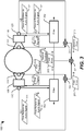
- the headset device 100 is configured to generate audio output.
- the headset device 100 may be configured to reproduce a reference sound originating from outside the headset device 100.
- the headset device 100 may reproduce the reference sound in a way that preserves an indication of a direction of origin of the reference sound (e.g., a phase difference between the sound as detected at a right ear of a user and the sound as detected at a left ear of the user, loudness of the sound as detected by a right ear of the user and as detected by the left ear of the user, etc.).
- a direction of origin of the reference sound e.g., a phase difference between the sound as detected at a right ear of a user and the sound as detected at a left ear of the user, loudness of the sound as detected by a right ear of the user and as detected by the left ear of the user, etc.
- the headset device 100 includes a first earpiece 108 and a second earpiece 118.
- the headset device 100 may correspond to closed type headset. Accordingly, the earpieces 108, 118 may correspond to over the ear earpieces configured to cover a user's ears or to earbuds configured to cover the user's ear canal.
- the first earpiece 108 may include a first microphone 110 (e.g., a reference microphone) and a first speaker 112.
- the second earpiece 118 may include a second microphone 120 (e.g., a reference microphone) and a second speaker 122.
- the first speaker 112 and the second speaker 122 may be positioned to output audio to the user's ear when the headset device 100 is worn by the user.
- the first microphone 110 and the second microphone 120 may be positioned to capture sounds that reach the outside of the earpieces 108, 118. Since the earpieces 108, 118 are configured to cover the ears of the user, the microphones 110, 120 may receive a sounds as the sound would ordinarily be received by the ears of the user in the absence of the headset device 100.
- the first earpiece 108 may further include a third microphone 114 (e.g., a feedback microphone).
- the third microphone 114 may be positioned so that the third microphone 114 receives (e.g., detects) sounds that reach the first ear while the user is wearing the headset device 100.
- the third microphone 114 may be positioned inside an earphone (e.g., with the first speaker 112) or on a portion of an earbud configured to be inserted into a human ear (e.g., with the first speaker 112).
- the third microphone 114 may receive sounds that originate outside the headset device 100 as distorted by the first earpiece 108 covering the first ear.
- the third microphone 114 may receive sound output by the first speaker 112.
- the second earpiece 118 may further include a fourth microphone 124 (e.g., a feedback microphone).
- the fourth microphone 124 may be positioned so that the fourth microphone 124 receives (e.g., detects) sounds that reach the second ear while the user is wearing the headset device 100.
- the fourth microphone 124 may be positioned inside an earphone (e.g., with the second speaker 122) or on a portion of an earbud configured to be inserted into a human ear (e.g., with the second speaker 122).
- the fourth microphone 124 may receive sounds that originate outside the headset device 100 as distorted by the second earpiece 118 covering the second ear.
- the fourth microphone 124 may receive sound output by the second speaker 122.
- the headset device 100 further includes a controller 102 and a memory 104.
- the controller 102 may correspond to a processor (e.g., a central processor unit, a digital signal processor, etc.). As explained further below with reference to FIG. 6 , the controller 102 may be included in a different device that is in communication with the headset device 100 in some examples.
- the memory 104 may include random access memory, static random access memory, a solid state drive, a hard disc drive, or any other type of memory device.
- the memory 104 may store filter data 106 (e.g., one or more filter coefficients).
- the filter data 106 may correspond to a single filter or to a plurality of filters (e.g., each of the earpieces 108, 118 may have a different corresponding filter).
- the first earpiece 108 and the second earpiece 118 may each have a distinct corresponding controller.
- the first earpiece 108 and the second earpiece 118 may each have a distinct corresponding memory device.
- the one or more filters may include hardware filters, software filters, or a combination thereof.
- the first microphone 110 receives a reference sound from a sound source.
- the reference sound may correspond to a test tone or other sound output by a speaker as part of a calibration process for the headset device 100.
- the reference sound may correspond to any other sound originating from a source other than the speakers 112, 122.
- the reference sound may correspond to a human talking, to a dog barking, to a car horn, or to any other sound.
- the first microphone 110 generates a first reference audio signal 111 based on the reference sound as detected by the first microphone 110.
- the second microphone 120 may also receive the reference sound from the sound source.
- properties of the reference sound as received at the first microphone 110 and as received at the second microphone 120 may be different.
- the reference sound as detected at the first microphone 110 may have a different amplitude (e.g., be louder, or quieter) than the reference sound as detected at the second microphone 120.
- a first phase of the reference sound as detected at the first microphone 110 may be different than a second phase of the reference sound as detected at the second microphone 120.
- the second microphone 120 generates a second reference audio signal 121 based on the reference sound as detected by the second microphone 120.
- the first reference audio signal 111 and the second reference audio signal 121 may have different properties due to positioning of the first microphone 110 and the second microphone 120 relative to the sound source.
- the first reference audio signal 111 may have a different phase than the second reference audio signal 121, a different amplitude (e.g., indicating volume) than the second reference audio signal 121, or a combination thereof.
- Human beings may utilize properties of sound to determine a location of a sound source.
- a difference in volume of a sound as detected by a person's left ear and the sound as detected by the person's right ear may indicate which ear is closer to the sound.
- the person may be able to determine a specific direction the sound originated from based on a magnitude of the difference.
- a phase difference (e.g., caused by the sound reaching one ear before the other) between the sound as detected by the left ear and the sound as detected by the right ear may indicate the direction.
- the controller 102 may generate a first signal 107 based on the first reference audio signal 111 and a second signal 117 based on the second reference audio signal 121.
- the controller 102 may correspond to different controllers associated with each of the earpieces 108, 118 and each of the first signal 107 and the second signal 117 may be generated by a different one of the controllers.
- the controller 102 may generate the first signal 107 and the second signal 117 using the filter data 106.
- the controller 102 may apply the filter data 106 to the first reference audio signal 111 to generate the first signal 107.
- the first signal 107 may correspond to a filtered version of the reference sound.
- the controller 102 may apply the filter data 106 to the second reference audio signal 121 to generate the second signal 117.
- the second signal 117 may correspond to a filtered version of the reference sound.
- the filter data 106 corresponds to more than one filter.
- a first filter may be used to generate the first signal 107
- a second filter may be used to generate the second signal 117.
- the first speaker 112 may generate first audio output based on the first signal 107
- the second speaker 122 may generate second audio output based on the second signal 117.
- the filter data 106 may be configured to reduce sound interference experienced by a user of the headset device 100.
- the reference sound may penetrate the first earpiece 108 so that the user's left ear may detect a first distorted (e.g., by the body of the first earpiece 108) version of the reference sound as well as the first audio output.
- the filter data 106 may be configured to reduce an effect of the first distorted version of the reference sound, as explained further below.
- the filter data 106 may be configured to generate the first signal 107 so that a sum of the first audio output and the first distorted version of the reference sound approximates the reference sound.
- the reference sound may penetrate the second earpiece 118 so that the user's right ear may detect a second distorted (e.g., by the body of the second earpiece 118) version of the reference sound as well as the second audio output.
- the filter data 106 may be configured to reduce an effect of the second distorted version of the reference sound, as explained further below. To illustrate, the filter data 106 may be configured to generate the second signal 117 so that a sum of the second audio output and the second distorted version of the reference sound approximates the reference sound.
- the third microphone 114 may receive the first audio output from the first speaker 112. In addition, the third microphone 114 may receive the first distorted version of the reference sound through the body of the first earpiece 108. The third microphone 114 may generate a first feedback audio signal 115 based on the first audio output and the first distorted version of the reference sound. Similarly, the fourth microphone 124 may receive the second audio output from the second speaker 122 and the second distorted version of the reference sound through the body of the second earpiece 118. The fourth microphone 124 may generate a second feedback audio signal 125 based on the second audio output and the second distorted version of the reference sound. The controller 102 may adjust the filter data 106 based on the first feedback audio signal 115 and the second feedback audio signal 125 to compensate (e.g., filter out) effects of the distorted versions of the reference sounds on the first and second outputs.
- compensate e.g., filter out
- the controller 102 may generate the first signal 107 and the second signal 117 based on a phase relationship (or other direction indicating relationship) between the first reference audio signal (e.g., the reference sound as detected at the first microphone 110) and the second reference audio signal 121 (e.g., the reference sound as detected at the second microphone 120). According to the invention, the controller 102 generates the first signal 107 and the second signal 117 so that a first phase difference between the first reference audio signal 111 and the second reference audio signal 121 is substantially equal to a second phase difference between the first feedback audio signal 115 and the second feedback audio signal 125.
- a phase relationship or other direction indicating relationship
- the controller 102 may constrain one or more filters corresponding to the filter data 106 when generating the first signal 107 and the second signal 117 so that the first phase difference is substantially equal to the second phase difference, as explained further below. Since the first feedback audio signal 115 corresponds to sound presented to a first ear of the user (e.g., a left ear or a right ear) and the second feedback audio signal 125 corresponds to sound presented to a second ear of the user, the user may be able to determine a location of the sound source of the reference sound.
- the controller 102 may generate the first signal 107 and the second signal 117 based on an amplitude relationship between the first reference audio signal 111 and the second reference audio signal 121.
- the controller 102 may generate the first signal 107 and the second signal 117 so that a first ratio of a first amplitude of the first reference audio signal 111 to a second amplitude of the second reference audio signal 121 is substantially equal to a second ratio of a third amplitude of the first feedback audio signal 115 to a fourth amplitude of the second feedback audio signal 125.
- the controller 102 may constrain one or more filters corresponding to the filter data 106 when generating the first signal 107 and the second signal 117 so that the first ratio is substantially equal to the second ratio, as explained further below. Since the first feedback audio signal 115 corresponds to sound presented to a first ear of the user (e.g., a left ear or a right ear) and the second feedback audio signal 125 corresponds to sound presented to a second ear of the user, the user may be able to determine a location of the sound source of the reference sound.
- the headset device 100 may enable pass through of a sound (e.g., the reference sound) originating from a source outside of the headset device 100. Further, the headset device 100 may determine one or more sound properties (e.g., amplitude, phase, etc.) of the sound as detected outside of each earpiece of the headset device 100. The headset device 100 may preserve one or more relationships between sound properties as detected at each of the earpieces and maintain the relationship(s) to generate pass through sound. Accordingly, the user may be able to determine a location of the source based on the pass through sound.
- a sound e.g., the reference sound
- the headset device 100 may determine one or more sound properties (e.g., amplitude, phase, etc.) of the sound as detected outside of each earpiece of the headset device 100.
- the headset device 100 may preserve one or more relationships between sound properties as detected at each of the earpieces and maintain the relationship(s) to generate pass through sound. Accordingly, the user may be able to determine a location of the
- a user of the headset device 100 may be located in a noisy environment, such as a coffee shop.
- the reference sound illustrated in FIG. 1 may correspond to a sound generated within the coffee shop.
- the reference sound may correspond to a voice of a barista asking the user for his or her order. Since the reference sound is passed through to the user as the first audio output and the second audio output, the user may be able to hear the barista even while wearing the headset device 100.
- the first audio output and the second audio output may have one or more location indicating relationships (e.g., phase difference, amplitude ratios) that are based on the reference sound as detected at each of the earpieces 108, 118. Accordingly, the user may be able to locate the barista based on the first audio output and the second audio output even if, for example, the user's back is turned to the barista.
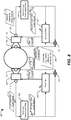
- the headset device 100 includes the first earpiece 108, the second earpiece 118, the first microphone 110, the second microphone 120, the third microphone 114, and the fourth microphone 124. While not shown, the headset device 100 of FIG. 2 may include the first speaker 112, the second speaker 122, the controller 102, and the memory 104.
- the headset device 100 includes a first filter 202 and a second filter 204.
- FIG. 2 illustrates an example of the filter data 106 corresponding to two different filters.
- the first filter 202 may include hardware or software.
- the second filter 204 may include hardware or software.
- the first filter 202 and the second filter 204 may correspond to the same hardware or software.
- the first filter 202 and the second filter 204 may operate differently based on different data (e.g., filter coefficients, such as the filter data 106) being applied to the common hardware or software.
- the first filter 202 may correspond to the first earpiece 108
- the second filter 204 may correspond to the second earpiece 118.
- the headset device 100 as illustrated in FIG. 2 further includes a first mixer 201 and a second mixer 211.
- the first filter 202 and the second filter 204 may operate on one or more sub-bands of a sound spectrum (e.g., corresponding to the range of sound frequencies audible to humans).
- the first filter 202 and 204 may operate separately on multiple different sub-bands within the sound spectrum.
- the first feedback audio signal 115 may correspond to sound as presented to a first ear of the user of the headset device 100.
- k corresponds to a sub-band of the sound spectrum
- the second feedback audio signal 125 may correspond to sound as presented to a second ear of the user of the headset device 100.
- the first signal 107 may be described by the expression H 1 adapt (k) x 1 ( k , t - t d )
- the second signal 117 may be described by the expression H 2 adapt (k) x 2 ( k,t - t d ) .
- the controller 102 may configure the filters 202, 204 according to the function argmin H 1 adapt k , H 2 adapt k ⁇ y 1 k t ⁇ x 1 k , t ⁇ t d ⁇ 2 + ⁇ y 2 k t ⁇ x 2 k , t ⁇ t d ⁇ 2 .
- the controller 102 may configure the first filter 202 (e.g., H 1 adapt (k)) and the second filter 204 (e.g., H 2 adapt (k)) to reduce a difference between sound detected by the third microphone 114 (e.g., y 1 ( k,t )) and sound detected by the first microphone 110 (e.g., x 1 ( k,t - t d )) and a difference between sound detected by the fourth microphone 124 (e.g., y 2 ( k , t )) and sound detected by the second microphone 120 (e.g., x 2 ( k,t - t d )) .
- the headset device 100 may pass through a sound detected outside the headset device 100 and the filters 202, 204 may reduce effects of distorted versions of the sound on a perception of a user.
- the first mixer 201 may generate a first error signal 203 based on a difference between feedback from the third microphone 114 (e.g., the first feedback audio signal 115) and the first reference audio signal 111.
- the first error signal 203 may be represented by the expression y 1 ( k,t ) - x 1 ( k,t - t d ) or or
- the controller may set the first filter 202 to reduce or minimize
- the second mixer 211 may generate a second error signal 213 based on a difference between feedback from the fourth microphone 124 (e.g., the second feedback audio signal 125) and the second reference audio signal 121.
- the second error signal 213 may be represented by the expression y 2 ( k , t ) - x 2 ( k , t - t d ) or
- the controller may set the second filter 204 to reduce or minimize
- the controller 102 may set the first filter 202 and the second filter 204 based on the function argmin H 1 adapt k , H 2 adapt k ⁇ y 1 k t ⁇ x 1 k , t ⁇ t d ⁇ 2 + ⁇ y 2 k t ⁇ x 2 k , t ⁇ t d ⁇ 2 , as explained above.
- the controller 102 may update the first filter 202 and the second filter 204 as new sounds are detected by the headset device 100. Accordingly, the first filter 202 and the second filter 204 may be adaptive filters.
- the controller 102 may apply one or more constraint(s) 206 when setting the first filter 202 and the second filter 204.
- the one or more constraints may be based on one or more relationship(s) between sound properties of x 1 ( k,t - t d ) and x 2 ( k,t-t d ) .
- the one or more constraints 206 may be based on a phase relationship (e.g., a phase difference) between x 1 ( k,t - t d ) and x 2 ( k,t - t d ) , based on an amplitude relationship between x 1 ( k,t - t d ) and x 2 ( k,t - t d ) , based on another relationship between x 1 ( k,t - t d ) and x 2 ( k,t - t d ) , or a combination thereof.
- a phase relationship e.g., a phase difference
- the controller 102 may determine filter coefficients (e.g., corresponding to the filter data 106) of the first filter 202 and the second filter 204 based on: argmin H 1 adapt k , H 2 adapt k ⁇ y 1 k t ⁇ x 1 k , t ⁇ t d ⁇ 2 + ⁇ y 2 k t ⁇ x 2 k , t ⁇ t d ⁇ 2 with the constraint that a first ratio of amplitudes of the first feedback audio signal 115 and the second feedback audio signal 125 is equal to (or substantially equal to) a second ratio of amplitudes of the first reference audio signal 111 and the second reference audio signal 121.
- the controller 102 may solve argmin H 1 adapt k , H 2 adapt k ⁇ y 1 k t ⁇ x 1 k , t ⁇ t d ⁇ 2 + ⁇ y 2 k t ⁇ x 2 k , t ⁇ t d ⁇ 2 with the constraint that a first phase difference between first feedback audio signal 115 and the second feedback audio signal 125 is equal to (or substantially equal to) a second phase difference between the first reference audio signal 111 and the second reference audio signal 121.
- the symbol " ⁇ " denotes phase.
- the controller 102 may apply more than one constraint.
- the filters 202, 204 may correspond to self-updating devices (e.g., adaptive filter devices with dedicated controllers).
- the one or more constraints 206 may correspond to a value indicating the phase relationship between x 1 ( k,t - t d ) and x 2 ( k,t - t d ) (e.g., the phase difference), a value indicating the amplitude relationship between x 1 ( k,t - t d ) and x 2 ( k,t - t d ) (e.g., the amplitude ratio), or a combination thereof.
- the controller 102 may send the one or more constraints 206 to the filters 202, 204.
- the first filter 202 may self-update based on the first error signal 203 and the one or more constraints 206.
- the second filter 204 may self-update based on the second error signal 213 and the one or more constraints 206.
- a signal output at one of earpieces 108, 118 may be based on an indication of sound detected at the other earpiece.
- the first signal 107 may be generated using the first filter 202 based on an indication of the second reference audio signal 121 (e.g., the one or more constraints 206 that is based on the second reference audio signal 121).
- the indication of the second reference audio signal 121 may include an indication of a phase value or of an amplitude value of the second reference audio signal 121.
- the first signal 107 may further be based on an indication of the second feedback audio signal 125 (e.g., the one or more constraints 206 that are based on the second feedback audio signal 125).
- the controller 102 may enable a sound passed through the headset device 100 by speakers 112, 122 and detected by the microphones 114, 124 to maintain sound properties of the sound as detected by the microphones 110, 120. Therefore, the headset device 100 may present the passed through sound to a user to enable the user to determine an origin point of a source of the sound.
- the headset device 100 includes the first earpiece 108, the second earpiece 118, the first microphone 110, the second microphone 120, the third microphone 114, the fourth microphone 124, the first mixer 201, and the second mixer 211. While not shown, the headset device 100 of FIG. 3 may include the first speaker 112, the second speaker 122, the controller 102, and the memory 104.
- the headset device 100 includes a filter 302.
- FIG. 3 illustrates an example of the filter data 106 corresponding to one filter.
- the filter 302 may include hardware or software.
- the filter 302 may be used to generate both the first signal 107 and the second signal 117.
- the headset device 100 of FIG. 3 further includes a third mixer 321.
- the filter 302 may operate on one or more sub-bands of a sound spectrum (e.g., corresponding to the range of sound frequencies audible to humans).
- the first filter 202 and 204 may operate separately on multiple different sub-bands within the sound spectrum.
- the first signal 107 may be described by the expression H adapt (k) x 1 ( k,t - t d ) and the second signal 117 may be described by the expression H adapt (k) x 2 ( k,t - t d ) .
- the controller 102 may configure the filter 302 according to the function argmin H adapt k ⁇ y 1 k t ⁇ x 1 k , t ⁇ t d ⁇ 2 + ⁇ y 2 k t ⁇ x 2 k , t ⁇ t d ⁇ 2 .
- the controller 102 may configure the filter 302 (e.g., H adapt (k)) to reduce a difference between sound detected by the third microphone 114 (e.g., y 1 ( k,t)) and sound detected by the first microphone 110 (e.g., x 1 ( k,t - t d )) and a difference between sound detected by the fourth microphone 124 (e.g., y 2 ( k,t )) and sound detected by the second microphone 120 (e.g., x 2 ( k,t - t d )) .
- the headset device 100 may pass through a sound detected outside the headset device 100, and the filter 302 may reduce effects of distorted versions of the sound on a perception of a user.
- the first mixer 201 may generate the first error signal 203 based on a difference between feedback from the third microphone 114 (e.g., the first feedback audio signal 115) and the first reference audio signal 111.
- the first error signal 203 may be represented by the expression y 1 ( k,t ) - x 1 ( k,t - t d ) or
- the second mixer 211 may generate the second error signal 213 based on a difference between feedback from the fourth microphone 124 (e.g., the second feedback audio signal 125) and the second reference audio signal 121.
- the second error signal 213 may be represented by the expression y 2 ( k,t ) - x 2 ( k, t - t d ) or
- the third mixer 321 may generate a third error signal 315 based on the first error signal 203 and the second error signal 213.
- the third error signal 315 may be represented by the expression
- the controller may set the filter 302 to reduce or minimize
- the controller set the filter 302 (e.g., set coefficients such as the filter data 106) based on the function argmin H adapt k ⁇ y 1 k t ⁇ x 1 k , t ⁇ t d ⁇ 2 + ⁇ y 2 k t ⁇ x 2 k , t ⁇ t d ⁇ 2 , as explained above.
- the controller 102 may update the filter 302 as sounds are detected by the headset device 100. Accordingly, the filter 302 may be an adaptive filter.
- the filter 302 (e.g., the filter data 106) is updated based on indications of sound detected at both earpieces 108, 118, sound generated at one earpiece may be based on sound detected at the other earpiece.
- the first signal 107 may be generated using the filter 302 which is updated based in part on the second reference audio signal 121.
- the headset device 100 may maintain one or more relationships between x 1 ( k,t - t d ) (e.g., the first reference audio signal 111) and x 2 ( k,t - t d ) (e.g., the second reference audio signal 121) in y 1 ( k,t ) (e.g., the first feedback audio signal 115) and y 2 ( k,t ) (e.g., the second feedback audio signal 125) without applying a constraint.
- x 1 ( k,t - t d ) e.g., the first reference audio signal 111
- x 2 ( k,t - t d ) e.g., the second reference audio signal 121
- y 1 ( k,t ) e.g., the first feedback audio signal 115
- y 2 ( k,t ) e.g., the second feedback audio signal 125
- a first amplitude relationship between the first feedback audio signal 115 and the second feedback audio signal 125 may substantially equal a second amplitude relationship between the first reference audio signal 111 and the second reference audio signal 121 (e.g., x 1 k , t ⁇ t d x 2 k , t ⁇ t d ).
- a first phase relationship between the first feedback audio signal 115 and the second feedback audio signal 125 may substantially equal a second phase relationship between the first reference audio signal 111 and the second reference audio signal 121 (e.g., ⁇ x 1 ( k,t - t d ) - ⁇ x 2 ( k,t - t d )) . That is, the headset device 100 may pass a sound through to a user's ears so that the passed through sound received at each ear maintains direction indicating properties.
- the headset device 100 includes the first earpiece 108 and the second earpiece 118, the first microphone 110, the second microphone 120, the third microphone 114, the fourth microphone 124, the first filter 202, the second filter 204, the first mixer 201, and the second mixer 211. While not shown, the headset device 100 of FIG. 4 may include the first speaker 112, the second speaker 122, the controller 102, and the memory 104.
- the headset device 100 further includes a first user-customized filter 402 and a second user-customized filter 404.
- FIG. 4 illustrates an example of the filter data 106 corresponding to four different filters.
- the first user-customized filter 402 may correspond to the first earpiece 108
- the second user-customized filter 404 may correspond to the second earpiece 118.
- FIG. 4 illustrates user-customized filters added to the two filter implementation of FIG. 2
- one or more user-customized filters may be incorporated into other implementations, such as the single filter implementation illustrated in FIG. 3 .
- the first user-customized filter 402 is applied (e.g., by the controller 102) to the first reference audio signal 111 to generate the first customized audio signal 411.
- the first user-customized filter 402 corresponds to a first ear of a user.
- the first user-customized filter 402 may be configured to apply one or more gains to frequency sub-bands of signals input into the first user-customized filter 402.
- the controller 102 may determine the first user-customized filter 402 based on user input indicating a user's perception of a plurality of frequency sub-bands of the sound spectrum via the first ear.
- the user input may be responsive to one or more test tones output to the first ear (e.g., by the first earpiece 108) over the plurality of frequency sub-bands.
- the user input may indicate user hearing perception over each of the frequency sub-bands.
- the first user-customized filter 402 may adjust sounds based on user hearing perception (e.g., due to hearing loss or other variations) of sounds via the first ear.
- the second user-customized filter 404 may be applied (e.g., by the controller 102) to the second reference audio signal 121 to generate the second customized audio signal 421.
- the second user-customized filter 404 may correspond to a second ear of the user.
- the second user-customized filter 404 may be configured to apply one or more gains to frequency sub-bands of signals input into the second user-customized filter 404.
- the controller 102 may determine the second user-customized filter 404 based on user input indicating the user's perception of a plurality of frequency sub-bands of the sound spectrum via the second ear.
- the user input may be responsive to one or more test tones output to the second ear (e.g., by the second earpiece 118) over the plurality of frequency sub-bands.
- the user input may indicate user hearing perception over each of the frequency sub-bands.
- the second user-customized filter 404 may adjust sounds based on a user hearing perception (e.g., due to hearing loss or other variations) of sounds via the first ear.
- the first customized audio signal 411 may replace the first reference audio signal 111 as input to the first filter 202.
- the second customized audio signal 421 may replace the second reference audio signal 121 as input to the second filter 204. Accordingly, the amplitudes of a plurality of frequency sub-bands of the first signal 107 may be tailored to the user's first ear, and amplitudes of a plurality of frequency sub-bands of the second signal 117 may be tailored to the user's second ear.
- the second feedback audio signal 125 may correspond to sound as presented to a second ear of the user of the headset device 100.
- the first signal 107 may be described by the expression H 1 adapt (k) x 1 ( k,t - t d )
- the second signal 117 may be described by the expression H 2 adapt (k) x 2 ( k,t - t d ) .
- the controller 102 may configure the filters 202, 204 according to the function argmin H 1 adapt k , H 2 adapt k ⁇ y 1 k t ⁇ H 1 user k x 1 k , t ⁇ t d ⁇ 2 + ⁇ y 2 ( k , t ) - H 2 user ( k ) x 2 ( k,t - t d ) ⁇ 2 , where H 1 user ( k ) x 1 corresponds to the first customized audio signal 411 and H 2 user ( k ) x 2 corresponds to the second customized audio signal 421.
- the controller 102 may configure the first filter 202 (e.g., H 1 adapt (k)) and the second filter 204 (e.g., H 2 adapt (k)) to reduce a difference between sound detected by the third microphone 114 (e.g., y 1 ( k,t)) and output of the first user-customized filter 402 (e.g., H 1 user ( k ) x 1 ( k,t - t d )) and a difference between sound detected by the fourth microphone 124 (e.g., y 2 ( k,t )) and output of the second user-customized filter 404 (e.g., H 2 user ( k ) x 2 ( k,t - t d )) .
- the headset device 100 may pass through an adjusted version of a sound detected outside the headset device 100, and the filters 202, 204 may reduce effects of distorted versions of the sound on a perception of a user.
- the controller 102 may apply one or more of the constraint(s) 206 when setting the first filter 202 and the second filter 204.
- the one or more constraints may be based on one or more relationship(s) between sound properties of H 1 user ( k ) x 1 ( k,t - t d ) and H 2 user ( k ) x 2 ( k,t - t d ) .
- the one or more constraints 206 may be based on a phase relationship (e.g., a phase difference) between H 1 user ( k ) x 1 ( k,t - t d ) and H 2 user ( k ) x 2 ( k,t - t d ) , based on an amplitude relationship between H 1 user ( k ) x 1 ( k,t - t d ) and H 2 user ( k ) x 2 ( k,t - t d ) , based on another relationship between H 1 user ( k ) x 1 ( k, t - t d ) and H 2 user ( k ) x 2 ( k,t - t d ) , or a combination thereof.
- a phase relationship e.g., a phase difference
- the controller 102 may determine filter coefficients (e.g,. corresponding to the filter data 106) of the first filter 202 and the second filter 204 based on: argmin H 1 adapt k , H 2 adapt k ⁇ y 1 k t ⁇ H 1 user k x 1 k , t ⁇ t d ⁇ 2 + ⁇ y 2 ( k,t ) - H 2 user ( k ) x 2 ( k,t - t d ⁇ 2 with the constraint that a first ratio of amplitudes of the first feedback audio signal 115 and the second feedback audio signal 125 is equal to (or substantially equal to) a second ratio of amplitudes of the first customized audio signal 411 and the second customized audio signal 421.
- the controller 102 may solve argmin H 1 adapt k , H 2 adapt k ⁇ y 1 k t ⁇ H 1 user k x 1 k , t ⁇ t d ⁇ 2 + ⁇ y 2 ( k,t ) - H 2 user ( k ) x 2 ( k,t - t d ) ⁇ 2 with the constraint that a first phase difference between first feedback audio signal 115 and the second feedback audio signal 125 is equal to a second phase difference between the first customized audio signal 411 and the second customized audio signal 421.
- the controller 102 may apply more than one constraint.
- the controller 102 may enable a user-customized sound passed through the headset device 100 by speakers 112, 122 and detected by the microphones 114, 124 to maintain sound properties of the sound as detected by the microphones 110, 120. Therefore, the headset device 100 may present the passed through sound to a user to enable the user to determine an origin point of a source of the sound.
- the user may have a hearing impairment in one or both ears that affects one or more sub-bands of the audio spectrum.
- the first user-customized filter 402 may apply one or more gains to sub-bands of the first reference audio signal 111 based on a profile associated with the user's left ear.
- the second user-customized filter 404 may apply one or more gains to sub-bands of the second reference audio signal. Accordingly, the user may be able to hear and to locate the barista despite the hearing impairment.
- the headset device 100 includes the first earpiece 108, the second earpiece 118, the first microphone 110, the second microphone 120, the third microphone 114, the fourth microphone 124, the first filter 202, the second filter 204, the first user-customized filter 402, the second user-customized filter 404, the first mixer 201, and the second mixer 211.
- the headset device 100 of FIG. 5 may include the first speaker 112, the second speaker 122, the controller 102, and the memory 104.
- the implementation illustrated in FIG. 5 may operate as described with reference to FIG. 4 except the first user-customized filter 402 and the second user-customized filter 404 may further receive sound data from an additional sound source.
- the first user-customized filter 402 may receive a first virtual sound signal and the second user-customized filter 404 may receive a second virtual sound signal.
- the first user-customized filter 402 may mix the first virtual sound with the first reference audio signal 111 and apply a plurality of gains to frequency sub-bands of the mixed signal to generate the first customized audio signal 411.
- the first virtual sound signal may correspond to a first component (e.g., left ear or right ear) of a virtual sound (e.g., a computer generated sound).
- the virtual sound may be generated by the controller 102 or received at the headset device 100 from another computing device.
- the first customized audio signal 411 may represent the reference sound and the virtual sound.
- the second user-customized filter 404 may mix the second virtual sound with the second reference audio signal 121 and apply a plurality of gains to frequency sub-bands of the mixed signal to generate the second customized audio signal 421.
- the second virtual sound signal may correspond to a second component (e.g., left ear or right ear) of the virtual sound.
- the second customized audio signal 421 may represent the reference sound and the virtual sound.
- FIG. 5 illustrates that the headset device 100 may pass a detected sound through to a user and may include a virtual sound in the passed-through sound.
- the passed-through sound may be adjusted using one or more filters to compensate for the sound penetrating the body of the headset device 100. Further, the sound may be passed through to each ear of the user in a way that maintains direction indicating relationships between sound heard at the left ear and sound heard at the right ear.
- the examples of the headset device 100 illustrated in FIGS. 2 and 3 may also support virtual sounds being mixed with pass through sounds.
- the first filter 202 may mix the first reference audio signal 111 with a virtual sound
- the second filter 204 may mix the second reference audio signal 121 with a virtual sound
- the filter 302 may mix the first reference audio signal 111 with a virtual sound
- the filter 302 may mix the second reference audio signal 121 with a virtual sound.
- any of the embodiments described herein may support mixing a virtual sound with a sound passed through to a user.
- the first virtual sound and the second virtual sound may correspond to left and right audio channels of a music output.
- the first signal 107 may include the barista's voice and the left audio channel of the music output.
- the second audio signal 117 may include the barista's voice and the music output. Accordingly, the user may be able to hear and locate the barista while listening to music with the headset device 100.
- FIG. 6 a block diagram of a particular illustrative implementation of a device (e.g., a wireless communication device) is depicted and generally designated 600.
- the device 600 may have more or fewer components than illustrated in FIG. 6 .
- the device 600 includes a processor 610, such as a central processing unit (CPU) or a digital signal processor (DSP), coupled to a memory 632.
- the processor 610 may include or correspond to the controller 102 illustrated in FIG. 1 .
- the memory 632 includes instructions 668 (e.g., executable instructions) such as computer-readable instructions or processor-readable instructions.
- the instructions 668 may include one or more instructions that are executable by a computer, such as the processor 610.
- FIG. 6 also illustrates a display controller 626 that is coupled to the processor 610 and to a display 628.
- a coder/decoder (CODEC) 634 may also be coupled to the processor 610.
- Speakers 636 and microphones 638 may be coupled to the CODEC 634.
- the speakers 636 may correspond to the first speaker 112 and the second speaker 122.
- the microphones 638 may correspond to the first microphone 110, the second microphone 120, the third microphone 114, and the fourth microphone 124.
- FIG. 6 also illustrates that a wireless interface 640, such as a wireless controller, and a transceiver 646 may be coupled to the processor 610 and to an antenna 642, such that wireless data received via the antenna 642, the transceiver 646, and the wireless interface 640 may be provided to the processor 610.
- the processor 610, the display controller 626, the memory 632, the CODEC 634, the wireless interface 640, and the transceiver 646 are included in a system-in-package or system-on-chip device 622.
- an input device 630 and a power supply 644 are coupled to the system-on-chip device 622.
- FIG. 6 illustrates that a wireless interface 640, such as a wireless controller, and a transceiver 646 may be coupled to the processor 610 and to an antenna 642, such that wireless data received via the antenna 642, the transceiver 646, and the wireless interface 640 may be provided to the processor 610.
- each of the display 628, the input device 630, the speakers 636, the microphones 638, the antenna 642, and the power supply 644 is external to the system-on-chip device 622.
- each of the display 628, the input device 630, the speakers 636, the microphones 638, the antenna 642, and the power supply 644 may be coupled to a component of the system-on-chip device 622, such as an interface or a controller.
- the device 600 may include a headset, such as the headset device 100.
- the headset may correspond to a virtual or augmented reality headset configured to present artificial (e.g., computer generated) auditory or visual sensory input to a user.
- the device 600 may include a mobile communication device, a smart phone, a cellular phone, a laptop computer, a computer, a tablet, a personal digital assistant, a display device, a television, a gaming console, a music player, a radio, a digital video player, a digital video disc (DVD) player, a tuner, a camera, a navigation device, a vehicle, a component of a vehicle, or any combination thereof in communication with or integrated with a headset.
- a mobile communication device such as the headset device 100.
- the headset may correspond to a virtual or augmented reality headset configured to present artificial (e.g., computer generated) auditory or visual sensory input to a user.
- the device 600 may include a mobile communication device, a smart phone, a cellular phone
- the memory 632 includes or stores the instructions 668 (e.g., executable instructions), such as computer-readable instructions or processor-readable instructions.
- the memory 632 may include or correspond to a non-transitory computer readable medium storing the instructions 668.
- the instructions 668 may include one or more instructions that are executable by a computer, such as the processor 610.
- the instructions 668 when executed by the processor 610, may cause the processor 610 to perform any of the operations described above with reference to FIGS. 1-5 .
- the instructions 668 may cause the processor 610 to operate as the controller 102 described above.
- the memory 632 further includes filter data 680.
- the filter data 680 may correspond to the filter data 106, the first filter 202, the second filter 204, the filter 302, the first user-customized filter 402, the second user-customized filter 404, or a combination thereof.
- the processor 610 may apply the filter data 680 to reference audio signals to generate new signals.
- the filter data 680 may correspond to one or more hardware filters accessible to the processor 610 rather than to software stored in the memory 632.
- the memory 632 further includes constraint data 682.
- the constraint data 682 may correspond to the one or more constraints 206 described above.
- the processor 610 may apply the constraint data 682 to the filter data 680 when generating filtered audio signals in order to maintain one or more direction indicating relationships, as explained above.
- the memory 632 may not include the constraint data 682, but the processor 610 may maintain the one or more direction indicating relationships as described, for example, with reference to FIG. 3 above.
- a headset device includes means for generating a first audio output.
- the means for generating the first audio output is configured to generate a first reference audio signal based on a reference sound.
- the means for generating the first audio output may correspond to the first earpiece 108, one or more components of the first earpiece 108, the controller 102, the filter data 106, the first filter 202, the filter 302, the first user-customized filter 402, the processor 610, the instructions 668, the filter data 680, the speakers 636, the CODEC 634, or a combination thereof.
- the headset device further includes means for generating a second audio output.
- the means for generating the second audio output is configured to generate a second reference audio signal based on the reference sound.
- the means for generating the second audio output may correspond to the second earpiece 118, one or more components of the second earpiece 118, the controller 102, the filter data 106, the second filter 204, the filter 302, the second user-customized filter 404, the processor 610, the instructions 668, the filter data 680, the speakers 636, the CODEC 634, or to a combination thereof.
- the headset device further includes means for generating a first signal and a second signal based on a phase relationship between the first reference audio signal and the second reference audio signal.
- the means for generating the first signal and the second signal is configured to output the first signal to the means for generating the first audio output and to output the second signal to the means for generating the second audio output.
- the means for generating the first signal and the second signal may correspond to the controller 102, the filter data 106, the first filter 202, the second filter 204, the first user-customized filter 402, the second user-customized filter 404, the processor 610, the instructions 668, the filter data 680, the codec 634, or a combination thereof.
- the headset device may further include first means for detecting the reference sound.
- the first means for detecting is included in the means for generating the first output.
- the first means for detecting is configured to generate the reference audio signal based on the reference sound.
- the first means for detecting may correspond to the third microphone 114 or to the microphones 638.
- the headset device may further include second means for detecting the reference sound.
- the second means for detecting is included in the means for generating the second output.
- the second means for detecting is configured to generate the reference audio signal based on the reference sound.
- the second means for detecting may correspond to the fourth microphone 124 or to the microphones 638.
- the device 600 may correspond to the headset device 100 or to another device in communication with the headset device 100.
- the processor 610 of the device 600 may correspond to the controller 102.
- the headset device 100 may include a wired and/or a wireless interface to exchange signals with the device 600. Accordingly, the device 600 may control the headset device 100, as described above.
- the device 600 may include a communications device, a fixed location data unit, a mobile location data unit, a mobile phone, a cellular phone, a satellite phone, a computer, a tablet, a portable computer, a display device, a media player, or a desktop computer.
- a communications device a fixed location data unit, a mobile location data unit, a mobile phone, a cellular phone, a satellite phone, a computer, a tablet, a portable computer, a display device, a media player, or a desktop computer.
- the device 600 may include a set top box, an entertainment unit, a navigation device, a personal digital assistant (PDA), a monitor, a computer monitor, a television, a radio, a satellite radio, a music player, a digital music player, a portable music player, a video player, a digital video player, a digital video disc (DVD) player, a portable digital video player, a vehicle, a component integrated within a vehicle, any other device that includes a processor or that stores or retrieves data or computer instructions, or a combination thereof.
- PDA personal digital assistant
- DVD digital video disc
- the system or the apparatus may include remote units, such as handheld personal communication systems (PCS) units, portable data units such as global positioning system (GPS) enabled devices, meter reading equipment, or any other device that includes a processor or that stores or retrieves data or computer instructions, or any combination thereof.
- remote units such as handheld personal communication systems (PCS) units, portable data units such as global positioning system (GPS) enabled devices, meter reading equipment, or any other device that includes a processor or that stores or retrieves data or computer instructions, or any combination thereof.
- PCS personal communication systems
- GPS global positioning system
- the device 600 may receive the first reference audio signal 111, the second reference audio signal 121, or a combination thereof from the headset device 100.
- the device 600 may receive the first reference audio signal 111, the second reference audio signal 121, or a combination thereof via a wired interface (not shown), the antenna 642, the transceiver 646, the wireless interface 640, or a combination thereof.
- the processor 600 may generate the first signal 107, the second signal 117, or a combination thereof, as described above with reference to FIGS. 1-5 .
- the device 600 may transmit the first signal 107, the second signal 117, or a combination thereof to the headset device 100 (e.g., via the wired interface, the antenna 642, the transceiver 646, the wireless interface 640, or a combination thereof).
- the device 600 operating in conjunction with the headset device 100 may perform the operations described above with reference to FIGS. 1-5 .
- the device 600 and the headset device 100 may exchange a different combination of signals in order to perform the operations described above with reference to FIGS. 1-5 .
- FIGS. 1-6 may illustrate systems, apparatuses, or methods according to the teachings of the disclosure, the disclosure is not limited to these illustrated systems, apparatuses, or methods.
- One or more functions or components of any of FIGS. 1-6 as illustrated or described herein may be combined with one or more other portions of another of FIGS. 1-6 . Accordingly, no single implementation described herein should be construed as limiting and implementations of the disclosure may be suitably combined without departing form the teachings of the disclosure.
- a software module may reside in random access memory (RAM), flash memory, read-only memory (ROM), programmable read-only memory (PROM), erasable programmable read-only memory (EPROM), electrically erasable programmable read-only memory (EEPROM), registers, hard disk, a removable disk, a compact disc read-only memory (CD-ROM), or any other form of non-transient storage medium known in the art.
- An exemplary storage medium is coupled to the processor such that the processor can read information from, and write information to, the storage medium.
- the storage medium may be integral to the processor.
- the processor and the storage medium may reside in an application-specific integrated circuit (ASIC).
- the ASIC may reside in a computing device or a user terminal.
- the processor and the storage medium may reside as discrete components in a computing device or user terminal.
Landscapes
- Engineering & Computer Science (AREA)
- Signal Processing (AREA)
- Physics & Mathematics (AREA)
- Acoustics & Sound (AREA)
- Health & Medical Sciences (AREA)
- General Health & Medical Sciences (AREA)
- Theoretical Computer Science (AREA)
- Otolaryngology (AREA)
- Multimedia (AREA)
- General Engineering & Computer Science (AREA)
- General Physics & Mathematics (AREA)
- Human Computer Interaction (AREA)
- Audiology, Speech & Language Pathology (AREA)
- Soundproofing, Sound Blocking, And Sound Damping (AREA)
- Headphones And Earphones (AREA)
- Stereophonic System (AREA)
Description
- The present application claims priority from commonly owned
U.S. Non-Provisional Patent Application No. 15/158,505 filed on May 18, 2016 - The present disclosure is generally related to devices that generate audio output.
- Advances in technology have resulted in smaller and more powerful computing devices. For example, a variety of portable personal computing devices, including wireless telephones, such as mobile and smart phones, tablets and laptop computers are small, lightweight, and easily carried by users. These devices can communicate voice and data packets over wireless networks. Further, many such devices incorporate additional functionality, such as a digital still camera, a digital video camera, a digital recorder, and an audio file player. Also, such devices can process executable instructions, including software applications, such as a web browser application, that can be used to access the Internet. As such, these devices can include significant computing and networking capabilities.
- Some computing devices are incorporated into virtual reality systems. Such a system may present virtual (e.g., computer generated) sensory information (e.g., visual information, audio information, etc.) to a user. For example, a virtual reality system may include a display device that displays virtual (e.g., computer generated) objects along with real world objects to a user. Accordingly, the user may perceive the virtual objects alongside the real world objects. In addition or in the alternative, virtual reality systems may include an audio output device that presents virtual (e.g., computer generated) sounds to the user. For example, a virtual sound may correspond to a virtual object. To illustrate, a virtual sound may correspond to computer generated speech associated with a virtual character. However, open-type audio systems (e.g., audio systems that do not cover an individual's ear completely) may broadcast sound to individuals other than the user. Further, closed-type audio systems (e.g., audio systems that cover the individual's ear completely) may occlude or partially occlude a user's ear. The occlusion of the user's ear caused by the closed-type audio system may distort sounds travelling to the user's ear from the real world environment.
-
US 2012/020485 A1 discloses a multi-microphone system for performing location-selective processing of an acoustic signal, wherein source location is indicated by directions of arrival relative to microphone pairs at opposite sides of a midsagittal plane of a user's head. -
US 2012/215519 A1 describes spatially selective augmentation of a multichannel audio signal in active noise cancellation (ANC) headsets. - In a particular aspect, a headset device as defined in claim 1 is provided. Preferred features of the headset device are defined in claims 2-8.
- Other aspects, advantages, and features of the present disclosure will become apparent after review of the entire application, including the following sections: Brief Description of the Drawings, Detailed Description, and the Claims.
-
-
FIG. 1 is a diagram of an illustrative example of a headset device according to the present invention; -
FIG. 2 is a diagram of another illustrative example of a headset device according to the present invention; -
FIG. 3 is a diagram of another illustrative example of a headset device, useful for understanding the present invention, but outside the scope of protection of the claims; -
FIG. 4 is a diagram of another illustrative example of a headset device, useful for understanding the present invention, but outside the scope of protection of the claims; -
FIG. 5 is a diagram of another illustrative example of a headset device, useful for understanding the present invention, but outside the scope of protection of the claims; and -
FIG. 6 is a block diagram of a device that may include a headset device, outside the scope of protection of the claims. - Particular aspects of the present disclosure are described below with reference to the drawings. In the description, common features are designated by common reference numbers throughout the drawings. As used herein, various terminology is used for the purpose of describing particular implementations only and is not intended to be limiting. For example, the singular forms "a," "an," and "the" are intended to include the plural forms as well, unless the context clearly indicates otherwise. It may be further understood that the terms "comprises" and "comprising" may be used interchangeably with "includes" or "including." Additionally, it will be understood that the term "wherein" may be used interchangeably with "where." As used herein, "exemplary" may indicate an example, an implementation, or an aspect, and should not be construed as limiting or as indicating a preference or a preferred implementation. As used herein, an ordinal term (e.g., "first," "second," "third," etc.) used to modify an element, such as a structure, a component, an operation, etc., does not by itself indicate any priority or order of the element with respect to another element, but rather merely distinguishes the element from another element having a same name (but for use of the ordinal term). As used herein, the term "set" refers to a grouping of one or more elements, and the term "plurality" refers to multiple elements.
- A device for outputting audio is disclosed. The device may be included in a closed-type audio system. The device may reproduce sounds from a sound source outside the closed-type audio system to compensate for distortion of the sounds due to occlusion of an individual's ear caused by the closed-type audio system. The device of the present invention reproduces the sounds in such a way as to indicate the direction of the sound source to the individual.
- Referring to
FIG. 1 , an illustrative implementation of a headset device is shown and generally designated 100. Theheadset device 100 is configured to generate audio output. For example, theheadset device 100 may be configured to reproduce a reference sound originating from outside theheadset device 100. Theheadset device 100 may reproduce the reference sound in a way that preserves an indication of a direction of origin of the reference sound (e.g., a phase difference between the sound as detected at a right ear of a user and the sound as detected at a left ear of the user, loudness of the sound as detected by a right ear of the user and as detected by the left ear of the user, etc.). - The
headset device 100 includes afirst earpiece 108 and asecond earpiece 118. Theheadset device 100 may correspond to closed type headset. Accordingly, theearpieces first earpiece 108 may include a first microphone 110 (e.g., a reference microphone) and afirst speaker 112. Thesecond earpiece 118 may include a second microphone 120 (e.g., a reference microphone) and asecond speaker 122. - The
first speaker 112 and thesecond speaker 122 may be positioned to output audio to the user's ear when theheadset device 100 is worn by the user. Thefirst microphone 110 and thesecond microphone 120 may be positioned to capture sounds that reach the outside of theearpieces earpieces microphones headset device 100. - The
first earpiece 108 may further include a third microphone 114 (e.g., a feedback microphone). Thethird microphone 114 may be positioned so that thethird microphone 114 receives (e.g., detects) sounds that reach the first ear while the user is wearing theheadset device 100. To illustrate, thethird microphone 114 may be positioned inside an earphone (e.g., with the first speaker 112) or on a portion of an earbud configured to be inserted into a human ear (e.g., with the first speaker 112). Thethird microphone 114 may receive sounds that originate outside theheadset device 100 as distorted by thefirst earpiece 108 covering the first ear. In addition, thethird microphone 114 may receive sound output by thefirst speaker 112. - The
second earpiece 118 may further include a fourth microphone 124 (e.g., a feedback microphone). Thefourth microphone 124 may be positioned so that thefourth microphone 124 receives (e.g., detects) sounds that reach the second ear while the user is wearing theheadset device 100. To illustrate, thefourth microphone 124 may be positioned inside an earphone (e.g., with the second speaker 122) or on a portion of an earbud configured to be inserted into a human ear (e.g., with the second speaker 122). Thefourth microphone 124 may receive sounds that originate outside theheadset device 100 as distorted by thesecond earpiece 118 covering the second ear. In addition, thefourth microphone 124 may receive sound output by thesecond speaker 122. - The
headset device 100 further includes acontroller 102 and amemory 104. Thecontroller 102 may correspond to a processor (e.g., a central processor unit, a digital signal processor, etc.). As explained further below with reference toFIG. 6 , thecontroller 102 may be included in a different device that is in communication with theheadset device 100 in some examples. Thememory 104 may include random access memory, static random access memory, a solid state drive, a hard disc drive, or any other type of memory device. Thememory 104 may store filter data 106 (e.g., one or more filter coefficients). In particular examples, the filter data 106 may correspond to a single filter or to a plurality of filters (e.g., each of theearpieces first earpiece 108 and thesecond earpiece 118 may each have a distinct corresponding controller. In addition, or in the alternative, thefirst earpiece 108 and thesecond earpiece 118 may each have a distinct corresponding memory device. The one or more filters may include hardware filters, software filters, or a combination thereof. - In operation, the
first microphone 110 receives a reference sound from a sound source. For example, the reference sound may correspond to a test tone or other sound output by a speaker as part of a calibration process for theheadset device 100. Alternatively, the reference sound may correspond to any other sound originating from a source other than thespeakers first microphone 110 generates a firstreference audio signal 111 based on the reference sound as detected by thefirst microphone 110. - The
second microphone 120 may also receive the reference sound from the sound source. However, properties of the reference sound as received at thefirst microphone 110 and as received at thesecond microphone 120 may be different. For example, due to an orientation of theheadset device 100 relative to the sound source, the reference sound as detected at thefirst microphone 110 may have a different amplitude (e.g., be louder, or quieter) than the reference sound as detected at thesecond microphone 120. As another example, a first phase of the reference sound as detected at thefirst microphone 110 may be different than a second phase of the reference sound as detected at thesecond microphone 120. Thesecond microphone 120 generates a secondreference audio signal 121 based on the reference sound as detected by thesecond microphone 120. The firstreference audio signal 111 and the secondreference audio signal 121 may have different properties due to positioning of thefirst microphone 110 and thesecond microphone 120 relative to the sound source. To illustrate, the firstreference audio signal 111 may have a different phase than the secondreference audio signal 121, a different amplitude (e.g., indicating volume) than the secondreference audio signal 121, or a combination thereof. - Human beings may utilize properties of sound to determine a location of a sound source. To illustrate, a difference in volume of a sound as detected by a person's left ear and the sound as detected by the person's right ear may indicate which ear is closer to the sound. Further, the person may be able to determine a specific direction the sound originated from based on a magnitude of the difference. Similarly, a phase difference (e.g., caused by the sound reaching one ear before the other) between the sound as detected by the left ear and the sound as detected by the right ear may indicate the direction.
- The
controller 102 may generate afirst signal 107 based on the firstreference audio signal 111 and asecond signal 117 based on the secondreference audio signal 121. Thecontroller 102 may correspond to different controllers associated with each of theearpieces first signal 107 and thesecond signal 117 may be generated by a different one of the controllers. - In particular implementations, the
controller 102 may generate thefirst signal 107 and thesecond signal 117 using the filter data 106. For example, thecontroller 102 may apply the filter data 106 to the firstreference audio signal 111 to generate thefirst signal 107. Thus, thefirst signal 107 may correspond to a filtered version of the reference sound. Similarly, thecontroller 102 may apply the filter data 106 to the secondreference audio signal 121 to generate thesecond signal 117. Thus, thesecond signal 117 may correspond to a filtered version of the reference sound. In particular examples, the filter data 106 corresponds to more than one filter. To illustrate, a first filter may be used to generate thefirst signal 107, and a second filter may be used to generate thesecond signal 117. Thefirst speaker 112 may generate first audio output based on thefirst signal 107, and thesecond speaker 122 may generate second audio output based on thesecond signal 117. - The filter data 106 may be configured to reduce sound interference experienced by a user of the
headset device 100. For example, the reference sound may penetrate thefirst earpiece 108 so that the user's left ear may detect a first distorted (e.g., by the body of the first earpiece 108) version of the reference sound as well as the first audio output. The filter data 106 may be configured to reduce an effect of the first distorted version of the reference sound, as explained further below. To illustrate, the filter data 106 may be configured to generate thefirst signal 107 so that a sum of the first audio output and the first distorted version of the reference sound approximates the reference sound. Similarly, the reference sound may penetrate thesecond earpiece 118 so that the user's right ear may detect a second distorted (e.g., by the body of the second earpiece 118) version of the reference sound as well as the second audio output. The filter data 106 may be configured to reduce an effect of the second distorted version of the reference sound, as explained further below. To illustrate, the filter data 106 may be configured to generate thesecond signal 117 so that a sum of the second audio output and the second distorted version of the reference sound approximates the reference sound. - The
third microphone 114 may receive the first audio output from thefirst speaker 112. In addition, thethird microphone 114 may receive the first distorted version of the reference sound through the body of thefirst earpiece 108. Thethird microphone 114 may generate a firstfeedback audio signal 115 based on the first audio output and the first distorted version of the reference sound. Similarly, thefourth microphone 124 may receive the second audio output from thesecond speaker 122 and the second distorted version of the reference sound through the body of thesecond earpiece 118. Thefourth microphone 124 may generate a secondfeedback audio signal 125 based on the second audio output and the second distorted version of the reference sound. Thecontroller 102 may adjust the filter data 106 based on the firstfeedback audio signal 115 and the secondfeedback audio signal 125 to compensate (e.g., filter out) effects of the distorted versions of the reference sounds on the first and second outputs. - The
controller 102 may generate thefirst signal 107 and thesecond signal 117 based on a phase relationship (or other direction indicating relationship) between the first reference audio signal (e.g., the reference sound as detected at the first microphone 110) and the second reference audio signal 121 (e.g., the reference sound as detected at the second microphone 120). According to the invention, thecontroller 102 generates thefirst signal 107 and thesecond signal 117 so that a first phase difference between the firstreference audio signal 111 and the secondreference audio signal 121 is substantially equal to a second phase difference between the firstfeedback audio signal 115 and the secondfeedback audio signal 125. For example, thecontroller 102 may constrain one or more filters corresponding to the filter data 106 when generating thefirst signal 107 and thesecond signal 117 so that the first phase difference is substantially equal to the second phase difference, as explained further below. Since the firstfeedback audio signal 115 corresponds to sound presented to a first ear of the user (e.g., a left ear or a right ear) and the secondfeedback audio signal 125 corresponds to sound presented to a second ear of the user, the user may be able to determine a location of the sound source of the reference sound. - In addition or in the alternative, the
controller 102 may generate thefirst signal 107 and thesecond signal 117 based on an amplitude relationship between the firstreference audio signal 111 and the secondreference audio signal 121. To illustrate, thecontroller 102 may generate thefirst signal 107 and thesecond signal 117 so that a first ratio of a first amplitude of the firstreference audio signal 111 to a second amplitude of the secondreference audio signal 121 is substantially equal to a second ratio of a third amplitude of the firstfeedback audio signal 115 to a fourth amplitude of the secondfeedback audio signal 125. For example, thecontroller 102 may constrain one or more filters corresponding to the filter data 106 when generating thefirst signal 107 and thesecond signal 117 so that the first ratio is substantially equal to the second ratio, as explained further below. Since the firstfeedback audio signal 115 corresponds to sound presented to a first ear of the user (e.g., a left ear or a right ear) and the secondfeedback audio signal 125 corresponds to sound presented to a second ear of the user, the user may be able to determine a location of the sound source of the reference sound. - Therefore, the
headset device 100 may enable pass through of a sound (e.g., the reference sound) originating from a source outside of theheadset device 100. Further, theheadset device 100 may determine one or more sound properties (e.g., amplitude, phase, etc.) of the sound as detected outside of each earpiece of theheadset device 100. Theheadset device 100 may preserve one or more relationships between sound properties as detected at each of the earpieces and maintain the relationship(s) to generate pass through sound. Accordingly, the user may be able to determine a location of the source based on the pass through sound. - In an illustrative use case, a user of the
headset device 100 may be located in a noisy environment, such as a coffee shop. In such an example, the reference sound illustrated inFIG. 1 may correspond to a sound generated within the coffee shop. For example, the reference sound may correspond to a voice of a barista asking the user for his or her order. Since the reference sound is passed through to the user as the first audio output and the second audio output, the user may be able to hear the barista even while wearing theheadset device 100. Further, since the first audio output and the second audio output may have one or more location indicating relationships (e.g., phase difference, amplitude ratios) that are based on the reference sound as detected at each of theearpieces - Referring to
FIG. 2 , another example of theheadset device 100 is shown. As illustrated inFIG. 2 , theheadset device 100 includes thefirst earpiece 108, thesecond earpiece 118, thefirst microphone 110, thesecond microphone 120, thethird microphone 114, and thefourth microphone 124. While not shown, theheadset device 100 ofFIG. 2 may include thefirst speaker 112, thesecond speaker 122, thecontroller 102, and thememory 104. - In the example of
FIG. 2 , theheadset device 100 includes afirst filter 202 and asecond filter 204. Thus,FIG. 2 illustrates an example of the filter data 106 corresponding to two different filters. Thefirst filter 202 may include hardware or software. Similarly, thesecond filter 204 may include hardware or software. In some embodiments, thefirst filter 202 and thesecond filter 204 may correspond to the same hardware or software. Thefirst filter 202 and thesecond filter 204 may operate differently based on different data (e.g., filter coefficients, such as the filter data 106) being applied to the common hardware or software. Thefirst filter 202 may correspond to thefirst earpiece 108, and thesecond filter 204 may correspond to thesecond earpiece 118. Theheadset device 100 as illustrated inFIG. 2 further includes afirst mixer 201 and asecond mixer 211. - The
first filter 202 and thesecond filter 204 may operate on one or more sub-bands of a sound spectrum (e.g., corresponding to the range of sound frequencies audible to humans). Thefirst filter feedback audio signal 115 may correspond to sound as presented to a first ear of the user of theheadset device 100. The firstfeedback audio signal 115 may be described by the equation y 1(k,t) = H1 adapt (k)x 1(k,t - td ) + H1 occlusion (k)x 1(k,t - td ), where k corresponds to a sub-band of the sound spectrum, t - td corresponds to a period of time, x 1(k, t - td ) is a function describing sound (e.g., the reference sound) in the sub-band detected by thefirst microphone 110 over the period of time, H1 adapt (k) is a function corresponding to thefirst filter 202, and H1 occlusion (k) is a function describing a distortion effect in the sub-band (e.g., to the reference sound) caused by the body of thefirst earpiece 108. The secondfeedback audio signal 125 may correspond to sound as presented to a second ear of the user of theheadset device 100. The secondfeedback audio signal 125 may be described by the equation y 2 (k,t) = H2 adapt (k)x 2(k, t - td ) + H2 occlusion (k)x 2(k,t - td ), where k corresponds to the sub-band of the sound spectrum, t - td corresponds to the period of time, x 2(k,t - td ) is a function describing sound (e.g., the reference sound) in the sub-band detected by the second microphone over the period of time, H2 adapt (k) is a function corresponding to thesecond filter 204, and H2 occlusion (k) is a function describing a distortion effect (e.g., to the reference sound) in the sub-band caused by the body of thesecond earpiece 118. Thefirst signal 107 may be described by the expression H1 adapt (k)x 1(k,t - td ), and thesecond signal 117 may be described by the expression H2 adapt (k)x 2(k,t - td ). - In order to reduce effects of H1 occlusion (k)x 1(k,t - td ) and H2 occlusion (k)x 2(k,t - td ) on sound presented to the first ear and the second ear, the
controller 102 may configure thefilters 
controller 102 may configure the first filter 202 (e.g., H1 adapt (k)) and the second filter 204 (e.g., H2 adapt (k)) to reduce a difference between sound detected by the third microphone 114 (e.g., y 1(k,t)) and sound detected by the first microphone 110 (e.g., x 1(k,t - td )) and a difference between sound detected by the fourth microphone 124 (e.g., y 2(k,t)) and sound detected by the second microphone 120 (e.g., x 2(k,t - td )). Accordingly, theheadset device 100 may pass through a sound detected outside theheadset device 100 and thefilters - In an illustrative example, the
first mixer 201 may generate afirst error signal 203 based on a difference between feedback from the third microphone 114 (e.g., the first feedback audio signal 115) and the firstreference audio signal 111. Thefirst error signal 203 may be represented by the expression y 1(k,t) - x 1(k,t - td ) or or ||y 1(k,t) - x 1(k,t - td )||2. The controller may set thefirst filter 202 to reduce or minimize ||y 1(k,t) - x 1(k,t - td )||2. Thesecond mixer 211 may generate asecond error signal 213 based on a difference between feedback from the fourth microphone 124 (e.g., the second feedback audio signal 125) and the secondreference audio signal 121. Thesecond error signal 213 may be represented by the expression y 2(k,t) - x2 (k,t - td ) or ||y 2(k,t) - x 2(k,t - td )∥2 . The controller may set thesecond filter 204 to reduce or minimize ||y 2 (k,t) - x 2(k,t - td )||2. Accordingly, thecontroller 102 may set thefirst filter 202 and thesecond filter 204 based on the function
controller 102 may update thefirst filter 202 and thesecond filter 204 as new sounds are detected by theheadset device 100. Accordingly, thefirst filter 202 and thesecond filter 204 may be adaptive filters. - The
controller 102 may apply one or more constraint(s) 206 when setting thefirst filter 202 and thesecond filter 204. The one or more constraints may be based on one or more relationship(s) between sound properties of x 1(k,t - td ) and x 2(k,t-td ). To illustrate, the one ormore constraints 206 may be based on a phase relationship (e.g., a phase difference) between x 1(k,t - td ) and x 2(k,t - td ), based on an amplitude relationship between x 1(k,t - td ) and x 2(k,t - td ), based on another relationship between x 1(k,t - td ) and x 2(k,t - td ), or a combination thereof. - In a particular example, the
controller 102 may determine filter coefficients (e.g., corresponding to the filter data 106) of thefirst filter 202 and thesecond filter 204 based on:
feedback audio signal 115 and the secondfeedback audio signal 125 is equal to (or substantially equal to) a second ratio of amplitudes of the firstreference audio signal 111 and the secondreference audio signal 121. The constraint may be expressed as
- In another example, the
controller 102 may solve
feedback audio signal 115 and the secondfeedback audio signal 125 is equal to (or substantially equal to) a second phase difference between the firstreference audio signal 111 and the secondreference audio signal 121. The constraint may be expressed as < y 1(k,t) -<y 1(k,t) = < x 1(k,t - td ) - < x 2(k,t - td ). As used herein, the symbol "<" denotes phase. In some examples, thecontroller 102 may apply more than one constraint. For example, thecontroller 102 may apply both constraints
- In some examples, the
filters more constraints 206 may correspond to a value indicating the phase relationship between x 1(k,t - td ) and x 2(k,t - td ) (e.g., the phase difference), a value indicating the amplitude relationship between x 1(k,t - td ) and x 2(k,t - td ) (e.g., the amplitude ratio), or a combination thereof. In such examples, thecontroller 102 may send the one ormore constraints 206 to thefilters first filter 202 may self-update based on thefirst error signal 203 and the one ormore constraints 206. Thesecond filter 204 may self-update based on thesecond error signal 213 and the one ormore constraints 206. - Thus, a signal output at one of
earpieces first signal 107 may be generated using thefirst filter 202 based on an indication of the second reference audio signal 121 (e.g., the one ormore constraints 206 that is based on the second reference audio signal 121). The indication of the secondreference audio signal 121 may include an indication of a phase value or of an amplitude value of the secondreference audio signal 121. Thefirst signal 107 may further be based on an indication of the second feedback audio signal 125 (e.g., the one ormore constraints 206 that are based on the second feedback audio signal 125). - By applying the constraint(s) 206 to the
filters controller 102 may enable a sound passed through theheadset device 100 byspeakers microphones microphones headset device 100 may present the passed through sound to a user to enable the user to determine an origin point of a source of the sound. - Referring to
FIG. 3 , another example of theheadset device 100 is shown. As illustrated inFIG. 3 , theheadset device 100 includes thefirst earpiece 108, thesecond earpiece 118, thefirst microphone 110, thesecond microphone 120, thethird microphone 114, thefourth microphone 124, thefirst mixer 201, and thesecond mixer 211. While not shown, theheadset device 100 ofFIG. 3 may include thefirst speaker 112, thesecond speaker 122, thecontroller 102, and thememory 104. - In the example of
FIG. 3 , theheadset device 100 includes afilter 302. Thus,FIG. 3 illustrates an example of the filter data 106 corresponding to one filter. Thefilter 302 may include hardware or software. Thefilter 302 may be used to generate both thefirst signal 107 and thesecond signal 117. Theheadset device 100 ofFIG. 3 further includes athird mixer 321. - The
filter 302 may operate on one or more sub-bands of a sound spectrum (e.g., corresponding to the range of sound frequencies audible to humans). Thefirst filter feedback audio signal 115 may be described by the equation y 1(k,t) = Hadapt (k)x 1(k,t - td ) + H1 occlusion (k)x 1(k,t - td ), where k corresponds to a sub-band of the sound spectrum, t - td corresponds to a period of time, x 1(k,t - td ) is a function describing sound (e.g., the reference sound) in the sub-band detected by thefirst microphone 110 over the period of time, Hadapt (k) is a function corresponding to thefilter 302, and H1 occlusion (k) is a function describing a distortion effect in the sub-band (e.g., to the reference sound) caused by the body of thefirst earpiece 108. The secondfeedback audio signal 125 may be described by the equation y 2(k,t) = Hadapt (k)x 2(k,t - td ) + H2 occlusion (k)x 2 (k,t - td ), where k corresponds to the sub-band of the sound spectrum, t - td corresponds to the period of time, x 2(k,t - td ) is a function describing sound (e.g., the reference sound) in the sub-band detected by the second microphone over the period of time, H2 adapt (k) is a function corresponding to thesecond filter 204, and H2 occlusion (k) is a function describing a distortion effect (e.g., to the reference sound) in the sub-band caused by the body of thesecond earpiece 118. Thus, thefirst signal 107 may be described by the expression Hadapt (k)x 1(k,t - td ) and thesecond signal 117 may be described by the expression Hadapt (k)x 2(k,t - td ). - In order to reduce effects of H1 occlusion (k)x 1(k,t - td ) and H2 occlusion (k)x 2 (k, t - td ), the
controller 102 may configure thefilter 302 according to the function
controller 102 may configure the filter 302 (e.g., Hadapt (k)) to reduce a difference between sound detected by the third microphone 114 (e.g., y 1(k,t)) and sound detected by the first microphone 110 (e.g., x 1(k,t - td )) and a difference between sound detected by the fourth microphone 124 (e.g., y 2(k,t)) and sound detected by the second microphone 120 (e.g., x 2(k,t - td )). Accordingly, theheadset device 100 may pass through a sound detected outside theheadset device 100, and thefilter 302 may reduce effects of distorted versions of the sound on a perception of a user. - In an illustrative example, the
first mixer 201 may generate thefirst error signal 203 based on a difference between feedback from the third microphone 114 (e.g., the first feedback audio signal 115) and the firstreference audio signal 111. Thefirst error signal 203 may be represented by the expression y 1(k,t) - x 1(k,t - td ) or ||y 1(k,t) - x 1(k, t - td )||2. Thesecond mixer 211 may generate thesecond error signal 213 based on a difference between feedback from the fourth microphone 124 (e.g., the second feedback audio signal 125) and the secondreference audio signal 121. Thesecond error signal 213 may be represented by the expression y 2(k,t) - x 2(k, t - td ) or ||y 2(k,t) - x 2(k,t - td )∥2. Thethird mixer 321 may generate athird error signal 315 based on thefirst error signal 203 and thesecond error signal 213. Thethird error signal 315 may be represented by the expression ||y 1(k,t) - x 1(k,t - td )∥2 + ∥y 2(k,t) - x 2(k,t - td )∥2 . The controller may set thefilter 302 to reduce or minimize ||y 1(k, t) - x 1(k, t - td)||2 + ||y 2(k,t) - x 2(k,t - td )2. Accordingly, the controller set the filter 302 (e.g., set coefficients such as the filter data 106) based on the function
controller 102 may update thefilter 302 as sounds are detected by theheadset device 100. Accordingly, thefilter 302 may be an adaptive filter. - Since the filter 302 (e.g., the filter data 106) is updated based on indications of sound detected at both
earpieces first signal 107 may be generated using thefilter 302 which is updated based in part on the secondreference audio signal 121. - By using the same filter (e.g., the filter 302) the
headset device 100 may maintain one or more relationships between x 1(k,t - td ) (e.g., the first reference audio signal 111) and x 2(k,t - td ) (e.g., the second reference audio signal 121) in y 1(k,t) (e.g., the first feedback audio signal 115) and y 2(k,t) (e.g., the second feedback audio signal 125) without applying a constraint. For example, a first amplitude relationship between the firstfeedback audio signal 115 and the second feedback audio signal 125 (e.g.,
reference audio signal 111 and the second reference audio signal 121 (e.g.,
feedback audio signal 115 and the second feedback audio signal 125 (e.g., < y 1(k,t) -<y 1(k,t)) may substantially equal a second phase relationship between the firstreference audio signal 111 and the second reference audio signal 121 (e.g., < x 1(k,t - td ) - < x 2(k,t - td )). That is, theheadset device 100 may pass a sound through to a user's ears so that the passed through sound received at each ear maintains direction indicating properties. - Referring to
FIG. 4 , another example of theheadset device 100 is shown. As illustrated inFIG. 4 , theheadset device 100 includes thefirst earpiece 108 and thesecond earpiece 118, thefirst microphone 110, thesecond microphone 120, thethird microphone 114, thefourth microphone 124, thefirst filter 202, thesecond filter 204, thefirst mixer 201, and thesecond mixer 211. While not shown, theheadset device 100 ofFIG. 4 may include thefirst speaker 112, thesecond speaker 122, thecontroller 102, and thememory 104. - In the example of
FIG. 4 , theheadset device 100 further includes a first user-customizedfilter 402 and a second user-customizedfilter 404. Thus,FIG. 4 illustrates an example of the filter data 106 corresponding to four different filters. The first user-customizedfilter 402 may correspond to thefirst earpiece 108, and the second user-customizedfilter 404 may correspond to thesecond earpiece 118. It should be noted that whileFIG. 4 illustrates user-customized filters added to the two filter implementation ofFIG. 2 , in other examples, one or more user-customized filters may be incorporated into other implementations, such as the single filter implementation illustrated inFIG. 3 . - In
FIG. 4 , the first user-customizedfilter 402 is applied (e.g., by the controller 102) to the firstreference audio signal 111 to generate the first customizedaudio signal 411. In a particular example, the first user-customizedfilter 402 corresponds to a first ear of a user. The first user-customizedfilter 402 may be configured to apply one or more gains to frequency sub-bands of signals input into the first user-customizedfilter 402. For example, thecontroller 102 may determine the first user-customizedfilter 402 based on user input indicating a user's perception of a plurality of frequency sub-bands of the sound spectrum via the first ear. The user input may be responsive to one or more test tones output to the first ear (e.g., by the first earpiece 108) over the plurality of frequency sub-bands. The user input may indicate user hearing perception over each of the frequency sub-bands. Accordingly, the first user-customizedfilter 402 may adjust sounds based on user hearing perception (e.g., due to hearing loss or other variations) of sounds via the first ear. - The second user-customized
filter 404 may be applied (e.g., by the controller 102) to the secondreference audio signal 121 to generate the second customizedaudio signal 421. The second user-customizedfilter 404 may correspond to a second ear of the user. The second user-customizedfilter 404 may be configured to apply one or more gains to frequency sub-bands of signals input into the second user-customizedfilter 404. For example, thecontroller 102 may determine the second user-customizedfilter 404 based on user input indicating the user's perception of a plurality of frequency sub-bands of the sound spectrum via the second ear. The user input may be responsive to one or more test tones output to the second ear (e.g., by the second earpiece 118) over the plurality of frequency sub-bands. The user input may indicate user hearing perception over each of the frequency sub-bands. Accordingly, the second user-customizedfilter 404 may adjust sounds based on a user hearing perception (e.g., due to hearing loss or other variations) of sounds via the first ear. - As compared to
FIG. 2 , the first customizedaudio signal 411 may replace the firstreference audio signal 111 as input to thefirst filter 202. Similarly, the second customizedaudio signal 421 may replace the secondreference audio signal 121 as input to thesecond filter 204. Accordingly, the amplitudes of a plurality of frequency sub-bands of thefirst signal 107 may be tailored to the user's first ear, and amplitudes of a plurality of frequency sub-bands of thesecond signal 117 may be tailored to the user's second ear. - In
FIG.4 , the firstfeedback audio signal 115 may be described by the equation y 1(k,t) = H1 adapt (k)H1 user (k)x 1(k,t-td )+ H1 occlusion (k)x 1(k,t - td ), where k corresponds to a sub-band of the sound spectrum, t - td corresponds to a period of time, x 1(k, t - td ) is a function describing sound (e.g., the reference sound) in the sub-band detected by thefirst microphone 110 over the period of time, H1 user (k) is a function corresponding to the first user-customizedfilter 402, H1 adapt (k) is a function corresponding to thefirst filter 202, and H1 occlusion (k) is a function describing a distortion effect in the sub-band (e.g., to the reference sound) caused by the body of thefirst earpiece 108. The secondfeedback audio signal 125 may correspond to sound as presented to a second ear of the user of theheadset device 100. The secondfeedback audio signal 125 may be described by the equation y 2(k,t) = H2 adapt (k)H2 user (k)x 2(k,t - td ) + H2 occlusion (k)x 2(k,t - td ), where k corresponds to the sub-band of the sound spectrum, t - td corresponds to the period of time, x 2(k, t - td ) is a function describing sound (e.g., the reference sound) in the sub-band detected by the second microphone over the period of time, H2 user (k) is a function corresponding to the second user-customizedfilter 404, H2 adapt (k) is a function corresponding to thesecond filter 204, and H2 occlusion (k) is a function describing a distortion effect (e.g., to the reference sound) in the sub-band caused by the body of thesecond earpiece 118. Thefirst signal 107 may be described by the expression H1 adapt (k)x 1(k,t - td ), and thesecond signal 117 may be described by the expression H2 adapt (k)x 2(k,t - td ). - In order to reduce effects of H1 occlusion (k)x 1(k,t - td ) and H2 occlusion (k)x2 (k,t - td ) on sound presented to the first ear and the second ear, the
controller 102 may configure thefilters 
audio signal 411 and H2 user (k)x 2 corresponds to the second customizedaudio signal 421. Thus, thecontroller 102 may configure the first filter 202 (e.g., H1 adapt (k)) and the second filter 204 (e.g., H2 adapt (k)) to reduce a difference between sound detected by the third microphone 114 (e.g., y 1(k,t)) and output of the first user-customized filter 402 (e.g., H1 user (k)x 1(k,t - td )) and a difference between sound detected by the fourth microphone 124 (e.g., y 2(k,t)) and output of the second user-customized filter 404 (e.g., H2 user (k)x 2 (k,t - td )). Accordingly, theheadset device 100 may pass through an adjusted version of a sound detected outside theheadset device 100, and thefilters - Further, the
controller 102 may apply one or more of the constraint(s) 206 when setting thefirst filter 202 and thesecond filter 204. The one or more constraints may be based on one or more relationship(s) between sound properties of H1 user (k)x 1(k,t - td ) and H2 user (k)x 2(k,t - td ). To illustrate, the one ormore constraints 206 may be based on a phase relationship (e.g., a phase difference) between H1 user (k)x 1(k,t - td ) and H2 user (k)x 2(k,t - td ), based on an amplitude relationship between H1 user (k)x1 (k,t - td ) and H2 user (k)x 2(k,t - td ), based on another relationship between H1 user (k)x 1(k, t - td ) and H2 user (k)x 2 (k,t - td ), or a combination thereof. - In a particular example, the
controller 102 may determine filter coefficients (e.g,. corresponding to the filter data 106) of thefirst filter 202 and thesecond filter 204 based on:
feedback audio signal 115 and the secondfeedback audio signal 125 is equal to (or substantially equal to) a second ratio of amplitudes of the first customizedaudio signal 411 and the second customizedaudio signal 421. That is, the constraint may be expressed as
- In another example, the
controller 102 may solve
feedback audio signal 115 and the secondfeedback audio signal 125 is equal to a second phase difference between the first customizedaudio signal 411 and the second customizedaudio signal 421. That is, the constraint may be expressed as< y 1(k,t) - < y 1(k,t) = < H1 user (k)x 1(k,t - td ) - < H2 user (k)x 2(k,t - td ). In some examples, thecontroller 102 may apply more than one constraint. For example, thecontroller 102 may apply both constraints
- By applying the constraint(s) 206 to the
filters controller 102 may enable a user-customized sound passed through theheadset device 100 byspeakers microphones microphones headset device 100 may present the passed through sound to a user to enable the user to determine an origin point of a source of the sound. - In the use case of the user of the
headset device 100 in the coffee shop, the user may have a hearing impairment in one or both ears that affects one or more sub-bands of the audio spectrum. The first user-customizedfilter 402 may apply one or more gains to sub-bands of the firstreference audio signal 111 based on a profile associated with the user's left ear. In addition or in the alternative, the second user-customizedfilter 404 may apply one or more gains to sub-bands of the second reference audio signal. Accordingly, the user may be able to hear and to locate the barista despite the hearing impairment. - Referring to
FIG. 5 , another example of theheadset device 100 is shown. As illustrated inFIG. 5 , theheadset device 100 includes thefirst earpiece 108, thesecond earpiece 118, thefirst microphone 110, thesecond microphone 120, thethird microphone 114, thefourth microphone 124, thefirst filter 202, thesecond filter 204, the first user-customizedfilter 402, the second user-customizedfilter 404, thefirst mixer 201, and thesecond mixer 211. While not shown, theheadset device 100 ofFIG. 5 may include thefirst speaker 112, thesecond speaker 122, thecontroller 102, and thememory 104. - The implementation illustrated in
FIG. 5 may operate as described with reference toFIG. 4 except the first user-customizedfilter 402 and the second user-customizedfilter 404 may further receive sound data from an additional sound source. For example, the first user-customizedfilter 402 may receive a first virtual sound signal and the second user-customizedfilter 404 may receive a second virtual sound signal. The first user-customizedfilter 402 may mix the first virtual sound with the firstreference audio signal 111 and apply a plurality of gains to frequency sub-bands of the mixed signal to generate the first customizedaudio signal 411. The first virtual sound signal may correspond to a first component (e.g., left ear or right ear) of a virtual sound (e.g., a computer generated sound). The virtual sound may be generated by thecontroller 102 or received at theheadset device 100 from another computing device. Thus, the first customizedaudio signal 411 may represent the reference sound and the virtual sound. - The second user-customized
filter 404 may mix the second virtual sound with the secondreference audio signal 121 and apply a plurality of gains to frequency sub-bands of the mixed signal to generate the second customizedaudio signal 421. The second virtual sound signal may correspond to a second component (e.g., left ear or right ear) of the virtual sound. Thus, the second customizedaudio signal 421 may represent the reference sound and the virtual sound. - Therefore,
FIG. 5 illustrates that theheadset device 100 may pass a detected sound through to a user and may include a virtual sound in the passed-through sound. The passed-through sound may be adjusted using one or more filters to compensate for the sound penetrating the body of theheadset device 100. Further, the sound may be passed through to each ear of the user in a way that maintains direction indicating relationships between sound heard at the left ear and sound heard at the right ear. It should be noted that the examples of theheadset device 100 illustrated inFIGS. 2 and3 may also support virtual sounds being mixed with pass through sounds. For example, thefirst filter 202 may mix the firstreference audio signal 111 with a virtual sound, thesecond filter 204 may mix the secondreference audio signal 121 with a virtual sound, thefilter 302 may mix the firstreference audio signal 111 with a virtual sound, or thefilter 302 may mix the secondreference audio signal 121 with a virtual sound. Accordingly, any of the embodiments described herein may support mixing a virtual sound with a sound passed through to a user. - In the use case of the user of the
headset device 100 in the coffee shop, the first virtual sound and the second virtual sound may correspond to left and right audio channels of a music output. Thefirst signal 107 may include the barista's voice and the left audio channel of the music output. Similarly, thesecond audio signal 117 may include the barista's voice and the music output. Accordingly, the user may be able to hear and locate the barista while listening to music with theheadset device 100. - Referring to
FIG. 6 , a block diagram of a particular illustrative implementation of a device (e.g., a wireless communication device) is depicted and generally designated 600. In various implementations, thedevice 600 may have more or fewer components than illustrated inFIG. 6 . - In a particular implementation, the
device 600 includes aprocessor 610, such as a central processing unit (CPU) or a digital signal processor (DSP), coupled to amemory 632. Theprocessor 610 may include or correspond to thecontroller 102 illustrated inFIG. 1 . - The
memory 632 includes instructions 668 (e.g., executable instructions) such as computer-readable instructions or processor-readable instructions. Theinstructions 668 may include one or more instructions that are executable by a computer, such as theprocessor 610. -
FIG. 6 also illustrates adisplay controller 626 that is coupled to theprocessor 610 and to adisplay 628. A coder/decoder (CODEC) 634 may also be coupled to theprocessor 610.Speakers 636 andmicrophones 638 may be coupled to theCODEC 634. Thespeakers 636 may correspond to thefirst speaker 112 and thesecond speaker 122. Themicrophones 638 may correspond to thefirst microphone 110, thesecond microphone 120, thethird microphone 114, and thefourth microphone 124. -
FIG. 6 also illustrates that awireless interface 640, such as a wireless controller, and atransceiver 646 may be coupled to theprocessor 610 and to anantenna 642, such that wireless data received via theantenna 642, thetransceiver 646, and thewireless interface 640 may be provided to theprocessor 610. In some implementations, theprocessor 610, thedisplay controller 626, thememory 632, theCODEC 634, thewireless interface 640, and thetransceiver 646 are included in a system-in-package or system-on-chip device 622. In some implementations, aninput device 630 and apower supply 644 are coupled to the system-on-chip device 622. Moreover, in a particular implementation, as illustrated inFIG. 6 , thedisplay 628, theinput device 630, thespeakers 636, themicrophones 638, theantenna 642, and thepower supply 644 are external to the system-on-chip device 622. In a particular implementation, each of thedisplay 628, theinput device 630, thespeakers 636, themicrophones 638, theantenna 642, and thepower supply 644 may be coupled to a component of the system-on-chip device 622, such as an interface or a controller. - The
device 600 may include a headset, such as theheadset device 100. The headset may correspond to a virtual or augmented reality headset configured to present artificial (e.g., computer generated) auditory or visual sensory input to a user. In alternative embodiments, thedevice 600 may include a mobile communication device, a smart phone, a cellular phone, a laptop computer, a computer, a tablet, a personal digital assistant, a display device, a television, a gaming console, a music player, a radio, a digital video player, a digital video disc (DVD) player, a tuner, a camera, a navigation device, a vehicle, a component of a vehicle, or any combination thereof in communication with or integrated with a headset. - In an illustrative implementation, the
memory 632 includes or stores the instructions 668 (e.g., executable instructions), such as computer-readable instructions or processor-readable instructions. For example, thememory 632 may include or correspond to a non-transitory computer readable medium storing theinstructions 668. Theinstructions 668 may include one or more instructions that are executable by a computer, such as theprocessor 610. Theinstructions 668, when executed by theprocessor 610, may cause theprocessor 610 to perform any of the operations described above with reference toFIGS. 1-5 . In particular, theinstructions 668 may cause theprocessor 610 to operate as thecontroller 102 described above. - The
memory 632 further includesfilter data 680. Thefilter data 680 may correspond to the filter data 106, thefirst filter 202, thesecond filter 204, thefilter 302, the first user-customizedfilter 402, the second user-customizedfilter 404, or a combination thereof. Theprocessor 610 may apply thefilter data 680 to reference audio signals to generate new signals. In alternative embodiments, thefilter data 680 may correspond to one or more hardware filters accessible to theprocessor 610 rather than to software stored in thememory 632. - The
memory 632 further includesconstraint data 682. Theconstraint data 682 may correspond to the one ormore constraints 206 described above. Theprocessor 610 may apply theconstraint data 682 to thefilter data 680 when generating filtered audio signals in order to maintain one or more direction indicating relationships, as explained above. In some examples, thememory 632 may not include theconstraint data 682, but theprocessor 610 may maintain the one or more direction indicating relationships as described, for example, with reference toFIG. 3 above. - In conjunction with the described aspects, a headset device includes means for generating a first audio output. The means for generating the first audio output is configured to generate a first reference audio signal based on a reference sound. The means for generating the first audio output may correspond to the
first earpiece 108, one or more components of thefirst earpiece 108, thecontroller 102, the filter data 106, thefirst filter 202, thefilter 302, the first user-customizedfilter 402, theprocessor 610, theinstructions 668, thefilter data 680, thespeakers 636, theCODEC 634, or a combination thereof. - The headset device further includes means for generating a second audio output. The means for generating the second audio output is configured to generate a second reference audio signal based on the reference sound. The means for generating the second audio output may correspond to the
second earpiece 118, one or more components of thesecond earpiece 118, thecontroller 102, the filter data 106, thesecond filter 204, thefilter 302, the second user-customizedfilter 404, theprocessor 610, theinstructions 668, thefilter data 680, thespeakers 636, theCODEC 634, or to a combination thereof. - The headset device further includes means for generating a first signal and a second signal based on a phase relationship between the first reference audio signal and the second reference audio signal. The means for generating the first signal and the second signal is configured to output the first signal to the means for generating the first audio output and to output the second signal to the means for generating the second audio output. The means for generating the first signal and the second signal may correspond to the
controller 102, the filter data 106, thefirst filter 202, thesecond filter 204, the first user-customizedfilter 402, the second user-customizedfilter 404, theprocessor 610, theinstructions 668, thefilter data 680, thecodec 634, or a combination thereof. - The headset device may further include first means for detecting the reference sound. The first means for detecting is included in the means for generating the first output. The first means for detecting is configured to generate the reference audio signal based on the reference sound. The first means for detecting may correspond to the
third microphone 114 or to themicrophones 638. - The headset device may further include second means for detecting the reference sound. The second means for detecting is included in the means for generating the second output. The second means for detecting is configured to generate the reference audio signal based on the reference sound. The second means for detecting may correspond to the
fourth microphone 124 or to themicrophones 638. - One or more of the disclosed aspects may be implemented in a system or an apparatus, such as the
device 600. Thedevice 600 may correspond to theheadset device 100 or to another device in communication with theheadset device 100. For example, theprocessor 610 of thedevice 600 may correspond to thecontroller 102. While not illustrated inFIGS. 1-5 , theheadset device 100 may include a wired and/or a wireless interface to exchange signals with thedevice 600. Accordingly, thedevice 600 may control theheadset device 100, as described above. - The
device 600 may include a communications device, a fixed location data unit, a mobile location data unit, a mobile phone, a cellular phone, a satellite phone, a computer, a tablet, a portable computer, a display device, a media player, or a desktop computer. Alternatively or additionally, thedevice 600 may include a set top box, an entertainment unit, a navigation device, a personal digital assistant (PDA), a monitor, a computer monitor, a television, a radio, a satellite radio, a music player, a digital music player, a portable music player, a video player, a digital video player, a digital video disc (DVD) player, a portable digital video player, a vehicle, a component integrated within a vehicle, any other device that includes a processor or that stores or retrieves data or computer instructions, or a combination thereof. As another illustrative, nonlimiting example, the system or the apparatus may include remote units, such as handheld personal communication systems (PCS) units, portable data units such as global positioning system (GPS) enabled devices, meter reading equipment, or any other device that includes a processor or that stores or retrieves data or computer instructions, or any combination thereof. - In an illustrative example, the
device 600 may receive the firstreference audio signal 111, the secondreference audio signal 121, or a combination thereof from theheadset device 100. For example, thedevice 600 may receive the firstreference audio signal 111, the secondreference audio signal 121, or a combination thereof via a wired interface (not shown), theantenna 642, thetransceiver 646, thewireless interface 640, or a combination thereof. Theprocessor 600 may generate thefirst signal 107, thesecond signal 117, or a combination thereof, as described above with reference toFIGS. 1-5 . Further, thedevice 600 may transmit thefirst signal 107, thesecond signal 117, or a combination thereof to the headset device 100 (e.g., via the wired interface, theantenna 642, thetransceiver 646, thewireless interface 640, or a combination thereof). Thus, thedevice 600 operating in conjunction with theheadset device 100 may perform the operations described above with reference toFIGS. 1-5 . In alternate examples, thedevice 600 and theheadset device 100 may exchange a different combination of signals in order to perform the operations described above with reference toFIGS. 1-5 . - Although one or more of
FIGS. 1-6 may illustrate systems, apparatuses, or methods according to the teachings of the disclosure, the disclosure is not limited to these illustrated systems, apparatuses, or methods. One or more functions or components of any ofFIGS. 1-6 as illustrated or described herein may be combined with one or more other portions of another ofFIGS. 1-6 . Accordingly, no single implementation described herein should be construed as limiting and implementations of the disclosure may be suitably combined without departing form the teachings of the disclosure. - Those of skill would further appreciate that the various illustrative logical blocks, configurations, modules, circuits, and algorithm steps described in connection with the implementations disclosed herein may be implemented as electronic hardware, computer software executed by a processor, or combinations of both. Various illustrative components, blocks, configurations, modules, circuits, and steps have been described above generally in terms of their functionality. Whether such functionality is implemented as hardware or processor executable instructions depends upon the particular application and design constraints imposed on the overall system. Skilled artisans may implement the described functionality in varying ways for each particular application, but such implementation decisions should not be interpreted as causing a departure from the scope of the present disclosure.
- The steps of a method or algorithm described in connection with the disclosure herein may be implemented directly in hardware, in a software module executed by a processor, or in a combination of the two. A software module may reside in random access memory (RAM), flash memory, read-only memory (ROM), programmable read-only memory (PROM), erasable programmable read-only memory (EPROM), electrically erasable programmable read-only memory (EEPROM), registers, hard disk, a removable disk, a compact disc read-only memory (CD-ROM), or any other form of non-transient storage medium known in the art. An exemplary storage medium is coupled to the processor such that the processor can read information from, and write information to, the storage medium. In the alternative, the storage medium may be integral to the processor. The processor and the storage medium may reside in an application-specific integrated circuit (ASIC). The ASIC may reside in a computing device or a user terminal. In the alternative, the processor and the storage medium may reside as discrete components in a computing device or user terminal.
- The previous description is provided to enable a person skilled in the art to make or use the disclosed implementations. Various modifications to these implementations will be readily apparent to those skilled in the art, and the principles defined herein may be applied to other implementations within the scope of the claims. Thus, the present disclosure is not intended to be limited to the implementations shown herein but is to be accorded the widest scope possible consistent with the principles and novel features as defined by the following claims.
Claims (8)
- A headset device (100) comprising:a first earpiece (108) configured to:receive a reference sound at a first reference microphone (110);generate, at the first reference microphone, a first reference audio signal (111) based on the reference sound;receive a first signal (107) from a controller (102);generate, at a first speaker (112), first audio output based on the first signal; andgenerate, at a first feedback microphone (114), a first feedback audio signal (115) based on detecting the first audio output and the reference sound;a second earpiece (118) configured to:receive the reference sound at a second reference microphone (120);generate, at the second reference microphone, a second reference audio signal (121) based on the reference sound, the second reference audio signal having a first phase difference relative to the first reference audio signal;receive a second signal (117) from the controller;generate, at a second speaker (122), second audio output based on the second signal; andgenerate, at a second feedback microphone (124), a second feedback audio signal (125) based on detecting the second audio output and the reference sound; andthe controller coupled to the first earpiece and to the second earpiece and configured to:generate the first signal and the second signal based on the first phase difference so that a second phase difference between the first feedback audio signal and the second feedback audio signal is substantially equal to the first phase difference;provide the first signal to the first earpiece; andprovide the second signal to the second earpiece.
- The headset device of claim 1, wherein the controller is configured to generate the first signal so that a difference between the first feedback audio signal and the first reference audio signal is reduced.
- The headset device of claim 1, wherein the controller is configured to:generate an error signal (203) based on a difference between the first feedback audio signal and the first reference audio signal;determine filter coefficients of a filter (202) to reduce the error signal, wherein the filter coefficients are based on the first phase difference; andgenerate the first signal by applying the filter, based on the filter coefficients, to the first reference audio signal.
- The headset device of claim 1, wherein the controller is configured to generate the first signal and the second signal based further on an amplitude relationship between the first reference audio signal and the second reference audio signal.
- The headset device of claim 4, wherein the amplitude relationship corresponds to a first ratio between a first amplitude of the first reference audio signal and a second amplitude of the second reference audio signal.
- The headset device of claim 1, wherein the controller is configured to generate the first signal by applying a first filter (202) to the first reference audio signal.
- The headset device of claim 6, wherein the controller is configured to generate the second signal by applying a second filter (204) to the second reference audio signal.
- The headset device of claim 7, wherein the first filter and the second filter are the same filter.
Priority Applications (1)
| Application Number | Priority Date | Filing Date | Title |
|---|---|---|---|
| EP20161929.3A EP3720106B1 (en) | 2016-05-18 | 2017-03-30 | Device for generating audio output |
Applications Claiming Priority (2)
| Application Number | Priority Date | Filing Date | Title |
|---|---|---|---|
| US15/158,505 US10547947B2 (en) | 2016-05-18 | 2016-05-18 | Device for generating audio output |
| PCT/US2017/025051 WO2017200646A1 (en) | 2016-05-18 | 2017-03-30 | Device for generating audio output |
Related Child Applications (2)
| Application Number | Title | Priority Date | Filing Date |
|---|---|---|---|
| EP20161929.3A Division EP3720106B1 (en) | 2016-05-18 | 2017-03-30 | Device for generating audio output |
| EP20161929.3A Division-Into EP3720106B1 (en) | 2016-05-18 | 2017-03-30 | Device for generating audio output |
Publications (2)
| Publication Number | Publication Date |
|---|---|
| EP3459231A1 EP3459231A1 (en) | 2019-03-27 |
| EP3459231B1 true EP3459231B1 (en) | 2020-04-15 |
Family
ID=58549217
Family Applications (2)
| Application Number | Title | Priority Date | Filing Date |
|---|---|---|---|
| EP20161929.3A Active EP3720106B1 (en) | 2016-05-18 | 2017-03-30 | Device for generating audio output |
| EP17718191.4A Active EP3459231B1 (en) | 2016-05-18 | 2017-03-30 | Device for generating audio output |
Family Applications Before (1)
| Application Number | Title | Priority Date | Filing Date |
|---|---|---|---|
| EP20161929.3A Active EP3720106B1 (en) | 2016-05-18 | 2017-03-30 | Device for generating audio output |
Country Status (9)
| Country | Link |
|---|---|
| US (1) | US10547947B2 (en) |
| EP (2) | EP3720106B1 (en) |
| JP (1) | JP6705020B2 (en) |
| KR (1) | KR102161962B1 (en) |
| CN (1) | CN109155802B (en) |
| BR (1) | BR112018073494A2 (en) |
| ES (1) | ES2806681T3 (en) |
| HU (1) | HUE049458T2 (en) |
| WO (1) | WO2017200646A1 (en) |
Families Citing this family (7)
| Publication number | Priority date | Publication date | Assignee | Title |
|---|---|---|---|---|
| US9906885B2 (en) | 2016-07-15 | 2018-02-27 | Qualcomm Incorporated | Methods and systems for inserting virtual sounds into an environment |
| US10978039B2 (en) * | 2018-05-18 | 2021-04-13 | Oshkosh Corporation | In-seat sound suppression |
| US10507138B1 (en) | 2018-06-08 | 2019-12-17 | Alvin J. Halfaker | Noise reduction earmuffs system and method |
| WO2019236110A1 (en) * | 2018-06-08 | 2019-12-12 | Halfaker Alvin J | Noise reduction earmuffs system and method |
| WO2020165667A1 (en) * | 2019-02-12 | 2020-08-20 | Rapture Innovation Labs Private Limited | An headphone system |
| SE543749C2 (en) | 2019-11-15 | 2021-07-13 | Hearezanz Ab | Volume dependent audio compensation |
| US11671752B2 (en) * | 2021-05-10 | 2023-06-06 | Qualcomm Incorporated | Audio zoom |
Family Cites Families (22)
| Publication number | Priority date | Publication date | Assignee | Title |
|---|---|---|---|---|
| WO1993026085A1 (en) | 1992-06-05 | 1993-12-23 | Noise Cancellation Technologies | Active/passive headset with speech filter |
| US5815582A (en) | 1994-12-02 | 1998-09-29 | Noise Cancellation Technologies, Inc. | Active plus selective headset |
| JP4126025B2 (en) * | 2004-03-16 | 2008-07-30 | 松下電器産業株式会社 | Sound processing apparatus, sound processing method, and sound processing program |
| US8189803B2 (en) | 2004-06-15 | 2012-05-29 | Bose Corporation | Noise reduction headset |
| WO2006036262A2 (en) | 2004-09-23 | 2006-04-06 | Thomson Licensing | Method and apparatus for controlling a headphone |
| JP2008167319A (en) * | 2006-12-28 | 2008-07-17 | Yamaha Corp | Headphone system, headphone drive controlling device, and headphone |
| EP2133866B1 (en) * | 2008-06-13 | 2016-02-17 | Harman Becker Automotive Systems GmbH | Adaptive noise control system |
| US8416959B2 (en) * | 2009-08-17 | 2013-04-09 | SPEAR Labs, LLC. | Hearing enhancement system and components thereof |
| JP2013530420A (en) | 2010-05-06 | 2013-07-25 | ドルビー ラボラトリーズ ライセンシング コーポレイション | Audio system equalization processing for portable media playback devices |
| JP5629372B2 (en) | 2010-06-17 | 2014-11-19 | ドルビー ラボラトリーズ ライセンシング コーポレイション | Method and apparatus for reducing the effects of environmental noise on a listener |
| US9025782B2 (en) | 2010-07-26 | 2015-05-05 | Qualcomm Incorporated | Systems, methods, apparatus, and computer-readable media for multi-microphone location-selective processing |
| JP5610945B2 (en) * | 2010-09-15 | 2014-10-22 | 株式会社オーディオテクニカ | Noise canceling headphones and noise canceling earmuffs |
| US9037458B2 (en) * | 2011-02-23 | 2015-05-19 | Qualcomm Incorporated | Systems, methods, apparatus, and computer-readable media for spatially selective audio augmentation |
| US9368096B2 (en) | 2011-12-20 | 2016-06-14 | Texas Instruments Incorporated | Method and system for active noise cancellation according to a type of noise |
| US20130304476A1 (en) * | 2012-05-11 | 2013-11-14 | Qualcomm Incorporated | Audio User Interaction Recognition and Context Refinement |
| JP5880340B2 (en) * | 2012-08-02 | 2016-03-09 | ソニー株式会社 | Headphone device, wearing state detection device, wearing state detection method |
| US20140126733A1 (en) | 2012-11-02 | 2014-05-08 | Daniel M. Gauger, Jr. | User Interface for ANR Headphones with Active Hear-Through |
| KR20140125969A (en) | 2013-04-19 | 2014-10-30 | 삼성전자주식회사 | Headset for removing noise sound |
| US9271077B2 (en) | 2013-12-17 | 2016-02-23 | Personics Holdings, Llc | Method and system for directional enhancement of sound using small microphone arrays |
| US10051371B2 (en) * | 2014-03-31 | 2018-08-14 | Bose Corporation | Headphone on-head detection using differential signal measurement |
| US9881619B2 (en) | 2016-03-25 | 2018-01-30 | Qualcomm Incorporated | Audio processing for an acoustical environment |
| US9906885B2 (en) | 2016-07-15 | 2018-02-27 | Qualcomm Incorporated | Methods and systems for inserting virtual sounds into an environment |
-
2016
- 2016-05-18 US US15/158,505 patent/US10547947B2/en active Active
-
2017
- 2017-03-30 WO PCT/US2017/025051 patent/WO2017200646A1/en active Search and Examination
- 2017-03-30 BR BR112018073494-2A patent/BR112018073494A2/en not_active IP Right Cessation
- 2017-03-30 EP EP20161929.3A patent/EP3720106B1/en active Active
- 2017-03-30 KR KR1020187032925A patent/KR102161962B1/en active IP Right Grant
- 2017-03-30 EP EP17718191.4A patent/EP3459231B1/en active Active
- 2017-03-30 HU HUE17718191A patent/HUE049458T2/en unknown
- 2017-03-30 ES ES17718191T patent/ES2806681T3/en active Active
- 2017-03-30 CN CN201780028354.9A patent/CN109155802B/en active Active
- 2017-03-30 JP JP2018560629A patent/JP6705020B2/en active Active
Non-Patent Citations (1)
| Title |
|---|
| None * |
Also Published As
| Publication number | Publication date |
|---|---|
| WO2017200646A1 (en) | 2017-11-23 |
| US10547947B2 (en) | 2020-01-28 |
| EP3720106A1 (en) | 2020-10-07 |
| JP2019518989A (en) | 2019-07-04 |
| EP3720106B1 (en) | 2022-11-23 |
| ES2806681T3 (en) | 2021-02-18 |
| JP6705020B2 (en) | 2020-06-03 |
| CN109155802B (en) | 2021-11-19 |
| KR20190008529A (en) | 2019-01-24 |
| HUE049458T2 (en) | 2020-09-28 |
| EP3459231A1 (en) | 2019-03-27 |
| BR112018073494A2 (en) | 2019-03-26 |
| KR102161962B1 (en) | 2020-10-21 |
| CN109155802A (en) | 2019-01-04 |
| US20170339491A1 (en) | 2017-11-23 |
Similar Documents
| Publication | Publication Date | Title |
|---|---|---|
| EP3459231B1 (en) | Device for generating audio output | |
| US11676568B2 (en) | Apparatus, method and computer program for adjustable noise cancellation | |
| US9992587B2 (en) | Binaural hearing system configured to localize a sound source | |
| US10269369B2 (en) | System and method of noise reduction for a mobile device | |
| US9508335B2 (en) | Active noise control and customized audio system | |
| US11740859B2 (en) | Media-compensated pass-through and mode-switching | |
| EP2992686B1 (en) | Earphone active noise control | |
| US10622005B2 (en) | Method and device for spectral expansion for an audio signal | |
| US10034087B2 (en) | Audio signal processing for listening devices | |
| WO2012114155A1 (en) | A transducer apparatus with in-ear microphone | |
| US10636436B2 (en) | Method and device for spectral expansion for an audio signal | |
| EP3840402B1 (en) | Wearable electronic device with low frequency noise reduction | |
| US20160173969A1 (en) | Multiple position earphone cable exit | |
| KR101971608B1 (en) | Wearable sound convertor | |
| US20170195779A9 (en) | Psycho-acoustic noise suppression | |
| US20230359430A1 (en) | Media-compensated pass-through and mode-switching | |
| US20230292032A1 (en) | Dual-speaker system |
Legal Events
| Date | Code | Title | Description |
|---|---|---|---|
| STAA | Information on the status of an ep patent application or granted ep patent |
Free format text: STATUS: UNKNOWN |
|
| STAA | Information on the status of an ep patent application or granted ep patent |
Free format text: STATUS: THE INTERNATIONAL PUBLICATION HAS BEEN MADE |
|
| PUAI | Public reference made under article 153(3) epc to a published international application that has entered the european phase |
Free format text: ORIGINAL CODE: 0009012 |
|
| STAA | Information on the status of an ep patent application or granted ep patent |
Free format text: STATUS: REQUEST FOR EXAMINATION WAS MADE |
|
| 17P | Request for examination filed |
Effective date: 20181207 |
|
| AK | Designated contracting states |
Kind code of ref document: A1 Designated state(s): AL AT BE BG CH CY CZ DE DK EE ES FI FR GB GR HR HU IE IS IT LI LT LU LV MC MK MT NL NO PL PT RO RS SE SI SK SM TR |
|
| AX | Request for extension of the european patent |
Extension state: BA ME |
|
| DAV | Request for validation of the european patent (deleted) | ||
| DAX | Request for extension of the european patent (deleted) | ||
| GRAP | Despatch of communication of intention to grant a patent |
Free format text: ORIGINAL CODE: EPIDOSNIGR1 |
|
| STAA | Information on the status of an ep patent application or granted ep patent |
Free format text: STATUS: GRANT OF PATENT IS INTENDED |
|
| INTG | Intention to grant announced |
Effective date: 20191009 |
|
| GRAS | Grant fee paid |
Free format text: ORIGINAL CODE: EPIDOSNIGR3 |
|
| GRAA | (expected) grant |
Free format text: ORIGINAL CODE: 0009210 |
|
| STAA | Information on the status of an ep patent application or granted ep patent |
Free format text: STATUS: THE PATENT HAS BEEN GRANTED |
|
| AK | Designated contracting states |
Kind code of ref document: B1 Designated state(s): AL AT BE BG CH CY CZ DE DK EE ES FI FR GB GR HR HU IE IS IT LI LT LU LV MC MK MT NL NO PL PT RO RS SE SI SK SM TR |
|
| REG | Reference to a national code |
Ref country code: CH Ref legal event code: EP |
|
| REG | Reference to a national code |
Ref country code: DE Ref legal event code: R096 Ref document number: 602017014807 Country of ref document: DE |
|
| REG | Reference to a national code |
Ref country code: IE Ref legal event code: FG4D |
|
| REG | Reference to a national code |
Ref country code: AT Ref legal event code: REF Ref document number: 1258657 Country of ref document: AT Kind code of ref document: T Effective date: 20200515 |
|
| REG | Reference to a national code |
Ref country code: CH Ref legal event code: NV Representative=s name: MAUCHER JENKINS PATENTANWAELTE AND RECHTSANWAE, DE |
|
| REG | Reference to a national code |
Ref country code: FI Ref legal event code: FGE |
|
| REG | Reference to a national code |
Ref country code: NL Ref legal event code: FP |
|
| REG | Reference to a national code |
Ref country code: LT Ref legal event code: MG4D |
|
| REG | Reference to a national code |
Ref country code: HU Ref legal event code: AG4A Ref document number: E049458 Country of ref document: HU |
|
| PG25 | Lapsed in a contracting state [announced via postgrant information from national office to epo] |
Ref country code: SE Free format text: LAPSE BECAUSE OF FAILURE TO SUBMIT A TRANSLATION OF THE DESCRIPTION OR TO PAY THE FEE WITHIN THE PRESCRIBED TIME-LIMIT Effective date: 20200415 Ref country code: NO Free format text: LAPSE BECAUSE OF FAILURE TO SUBMIT A TRANSLATION OF THE DESCRIPTION OR TO PAY THE FEE WITHIN THE PRESCRIBED TIME-LIMIT Effective date: 20200715 Ref country code: GR Free format text: LAPSE BECAUSE OF FAILURE TO SUBMIT A TRANSLATION OF THE DESCRIPTION OR TO PAY THE FEE WITHIN THE PRESCRIBED TIME-LIMIT Effective date: 20200716 Ref country code: LT Free format text: LAPSE BECAUSE OF FAILURE TO SUBMIT A TRANSLATION OF THE DESCRIPTION OR TO PAY THE FEE WITHIN THE PRESCRIBED TIME-LIMIT Effective date: 20200415 Ref country code: PT Free format text: LAPSE BECAUSE OF FAILURE TO SUBMIT A TRANSLATION OF THE DESCRIPTION OR TO PAY THE FEE WITHIN THE PRESCRIBED TIME-LIMIT Effective date: 20200817 Ref country code: IS Free format text: LAPSE BECAUSE OF FAILURE TO SUBMIT A TRANSLATION OF THE DESCRIPTION OR TO PAY THE FEE WITHIN THE PRESCRIBED TIME-LIMIT Effective date: 20200815 |
|
| REG | Reference to a national code |
Ref country code: AT Ref legal event code: MK05 Ref document number: 1258657 Country of ref document: AT Kind code of ref document: T Effective date: 20200415 |
|
| PG25 | Lapsed in a contracting state [announced via postgrant information from national office to epo] |
Ref country code: BG Free format text: LAPSE BECAUSE OF FAILURE TO SUBMIT A TRANSLATION OF THE DESCRIPTION OR TO PAY THE FEE WITHIN THE PRESCRIBED TIME-LIMIT Effective date: 20200715 Ref country code: RS Free format text: LAPSE BECAUSE OF FAILURE TO SUBMIT A TRANSLATION OF THE DESCRIPTION OR TO PAY THE FEE WITHIN THE PRESCRIBED TIME-LIMIT Effective date: 20200415 Ref country code: LV Free format text: LAPSE BECAUSE OF FAILURE TO SUBMIT A TRANSLATION OF THE DESCRIPTION OR TO PAY THE FEE WITHIN THE PRESCRIBED TIME-LIMIT Effective date: 20200415 Ref country code: HR Free format text: LAPSE BECAUSE OF FAILURE TO SUBMIT A TRANSLATION OF THE DESCRIPTION OR TO PAY THE FEE WITHIN THE PRESCRIBED TIME-LIMIT Effective date: 20200415 |
|
| PG25 | Lapsed in a contracting state [announced via postgrant information from national office to epo] |
Ref country code: AL Free format text: LAPSE BECAUSE OF FAILURE TO SUBMIT A TRANSLATION OF THE DESCRIPTION OR TO PAY THE FEE WITHIN THE PRESCRIBED TIME-LIMIT Effective date: 20200415 |
|
| REG | Reference to a national code |
Ref country code: DE Ref legal event code: R097 Ref document number: 602017014807 Country of ref document: DE |
|
| PG25 | Lapsed in a contracting state [announced via postgrant information from national office to epo] |
Ref country code: IT Free format text: LAPSE BECAUSE OF FAILURE TO SUBMIT A TRANSLATION OF THE DESCRIPTION OR TO PAY THE FEE WITHIN THE PRESCRIBED TIME-LIMIT Effective date: 20200415 Ref country code: RO Free format text: LAPSE BECAUSE OF FAILURE TO SUBMIT A TRANSLATION OF THE DESCRIPTION OR TO PAY THE FEE WITHIN THE PRESCRIBED TIME-LIMIT Effective date: 20200415 Ref country code: DK Free format text: LAPSE BECAUSE OF FAILURE TO SUBMIT A TRANSLATION OF THE DESCRIPTION OR TO PAY THE FEE WITHIN THE PRESCRIBED TIME-LIMIT Effective date: 20200415 Ref country code: SM Free format text: LAPSE BECAUSE OF FAILURE TO SUBMIT A TRANSLATION OF THE DESCRIPTION OR TO PAY THE FEE WITHIN THE PRESCRIBED TIME-LIMIT Effective date: 20200415 Ref country code: EE Free format text: LAPSE BECAUSE OF FAILURE TO SUBMIT A TRANSLATION OF THE DESCRIPTION OR TO PAY THE FEE WITHIN THE PRESCRIBED TIME-LIMIT Effective date: 20200415 Ref country code: AT Free format text: LAPSE BECAUSE OF FAILURE TO SUBMIT A TRANSLATION OF THE DESCRIPTION OR TO PAY THE FEE WITHIN THE PRESCRIBED TIME-LIMIT Effective date: 20200415 Ref country code: CZ Free format text: LAPSE BECAUSE OF FAILURE TO SUBMIT A TRANSLATION OF THE DESCRIPTION OR TO PAY THE FEE WITHIN THE PRESCRIBED TIME-LIMIT Effective date: 20200415 |
|
| REG | Reference to a national code |
Ref country code: ES Ref legal event code: FG2A Ref document number: 2806681 Country of ref document: ES Kind code of ref document: T3 Effective date: 20210218 |
|
| PLBE | No opposition filed within time limit |
Free format text: ORIGINAL CODE: 0009261 |
|
| STAA | Information on the status of an ep patent application or granted ep patent |
Free format text: STATUS: NO OPPOSITION FILED WITHIN TIME LIMIT |
|
| PG25 | Lapsed in a contracting state [announced via postgrant information from national office to epo] |
Ref country code: PL Free format text: LAPSE BECAUSE OF FAILURE TO SUBMIT A TRANSLATION OF THE DESCRIPTION OR TO PAY THE FEE WITHIN THE PRESCRIBED TIME-LIMIT Effective date: 20200415 Ref country code: SK Free format text: LAPSE BECAUSE OF FAILURE TO SUBMIT A TRANSLATION OF THE DESCRIPTION OR TO PAY THE FEE WITHIN THE PRESCRIBED TIME-LIMIT Effective date: 20200415 |
|
| 26N | No opposition filed |
Effective date: 20210118 |
|
| PGFP | Annual fee paid to national office [announced via postgrant information from national office to epo] |
Ref country code: FI Payment date: 20210223 Year of fee payment: 5 |
|
| PG25 | Lapsed in a contracting state [announced via postgrant information from national office to epo] |
Ref country code: SI Free format text: LAPSE BECAUSE OF FAILURE TO SUBMIT A TRANSLATION OF THE DESCRIPTION OR TO PAY THE FEE WITHIN THE PRESCRIBED TIME-LIMIT Effective date: 20200415 |
|
| PGFP | Annual fee paid to national office [announced via postgrant information from national office to epo] |
Ref country code: HU Payment date: 20210222 Year of fee payment: 5 |
|
| PG25 | Lapsed in a contracting state [announced via postgrant information from national office to epo] |
Ref country code: MC Free format text: LAPSE BECAUSE OF FAILURE TO SUBMIT A TRANSLATION OF THE DESCRIPTION OR TO PAY THE FEE WITHIN THE PRESCRIBED TIME-LIMIT Effective date: 20200415 |
|
| REG | Reference to a national code |
Ref country code: BE Ref legal event code: MM Effective date: 20210331 |
|
| PG25 | Lapsed in a contracting state [announced via postgrant information from national office to epo] |
Ref country code: IE Free format text: LAPSE BECAUSE OF NON-PAYMENT OF DUE FEES Effective date: 20210330 Ref country code: LU Free format text: LAPSE BECAUSE OF NON-PAYMENT OF DUE FEES Effective date: 20210330 |
|
| PG25 | Lapsed in a contracting state [announced via postgrant information from national office to epo] |
Ref country code: BE Free format text: LAPSE BECAUSE OF NON-PAYMENT OF DUE FEES Effective date: 20210331 |
|
| REG | Reference to a national code |
Ref country code: FI Ref legal event code: MAE |
|
| PG25 | Lapsed in a contracting state [announced via postgrant information from national office to epo] |
Ref country code: FI Free format text: LAPSE BECAUSE OF NON-PAYMENT OF DUE FEES Effective date: 20220330 |
|
| PG25 | Lapsed in a contracting state [announced via postgrant information from national office to epo] |
Ref country code: HU Free format text: LAPSE BECAUSE OF NON-PAYMENT OF DUE FEES Effective date: 20220331 |
|
| PG25 | Lapsed in a contracting state [announced via postgrant information from national office to epo] |
Ref country code: CY Free format text: LAPSE BECAUSE OF FAILURE TO SUBMIT A TRANSLATION OF THE DESCRIPTION OR TO PAY THE FEE WITHIN THE PRESCRIBED TIME-LIMIT Effective date: 20200415 |
|
| PGFP | Annual fee paid to national office [announced via postgrant information from national office to epo] |
Ref country code: NL Payment date: 20240212 Year of fee payment: 8 |
|
| PG25 | Lapsed in a contracting state [announced via postgrant information from national office to epo] |
Ref country code: MK Free format text: LAPSE BECAUSE OF FAILURE TO SUBMIT A TRANSLATION OF THE DESCRIPTION OR TO PAY THE FEE WITHIN THE PRESCRIBED TIME-LIMIT Effective date: 20200415 |
|
| PGFP | Annual fee paid to national office [announced via postgrant information from national office to epo] |
Ref country code: DE Payment date: 20240209 Year of fee payment: 8 Ref country code: GB Payment date: 20240208 Year of fee payment: 8 |
|
| PGFP | Annual fee paid to national office [announced via postgrant information from national office to epo] |
Ref country code: FR Payment date: 20240209 Year of fee payment: 8 |
|
| PGFP | Annual fee paid to national office [announced via postgrant information from national office to epo] |
Ref country code: CH Payment date: 20240401 Year of fee payment: 8 |
|
| PGFP | Annual fee paid to national office [announced via postgrant information from national office to epo] |
Ref country code: ES Payment date: 20240408 Year of fee payment: 8 |