EP3458716B1 - System for mounting a refrigerant compressor housing to a base plate - Google Patents
System for mounting a refrigerant compressor housing to a base plate Download PDFInfo
- Publication number
- EP3458716B1 EP3458716B1 EP17798686.6A EP17798686A EP3458716B1 EP 3458716 B1 EP3458716 B1 EP 3458716B1 EP 17798686 A EP17798686 A EP 17798686A EP 3458716 B1 EP3458716 B1 EP 3458716B1
- Authority
- EP
- European Patent Office
- Prior art keywords
- clip
- slot
- base plate
- screw pin
- neck portion
- Prior art date
- Legal status (The legal status is an assumption and is not a legal conclusion. Google has not performed a legal analysis and makes no representation as to the accuracy of the status listed.)
- Active
Links
Images



Classifications
-
- F—MECHANICAL ENGINEERING; LIGHTING; HEATING; WEAPONS; BLASTING
- F04—POSITIVE - DISPLACEMENT MACHINES FOR LIQUIDS; PUMPS FOR LIQUIDS OR ELASTIC FLUIDS
- F04B—POSITIVE-DISPLACEMENT MACHINES FOR LIQUIDS; PUMPS
- F04B39/00—Component parts, details, or accessories, of pumps or pumping systems specially adapted for elastic fluids, not otherwise provided for in, or of interest apart from, groups F04B25/00 - F04B37/00
- F04B39/12—Casings; Cylinders; Cylinder heads; Fluid connections
- F04B39/121—Casings
-
- F—MECHANICAL ENGINEERING; LIGHTING; HEATING; WEAPONS; BLASTING
- F04—POSITIVE - DISPLACEMENT MACHINES FOR LIQUIDS; PUMPS FOR LIQUIDS OR ELASTIC FLUIDS
- F04B—POSITIVE-DISPLACEMENT MACHINES FOR LIQUIDS; PUMPS
- F04B39/00—Component parts, details, or accessories, of pumps or pumping systems specially adapted for elastic fluids, not otherwise provided for in, or of interest apart from, groups F04B25/00 - F04B37/00
-
- F—MECHANICAL ENGINEERING; LIGHTING; HEATING; WEAPONS; BLASTING
- F04—POSITIVE - DISPLACEMENT MACHINES FOR LIQUIDS; PUMPS FOR LIQUIDS OR ELASTIC FLUIDS
- F04B—POSITIVE-DISPLACEMENT MACHINES FOR LIQUIDS; PUMPS
- F04B39/00—Component parts, details, or accessories, of pumps or pumping systems specially adapted for elastic fluids, not otherwise provided for in, or of interest apart from, groups F04B25/00 - F04B37/00
- F04B39/14—Provisions for readily assembling or disassembling
-
- F—MECHANICAL ENGINEERING; LIGHTING; HEATING; WEAPONS; BLASTING
- F04—POSITIVE - DISPLACEMENT MACHINES FOR LIQUIDS; PUMPS FOR LIQUIDS OR ELASTIC FLUIDS
- F04B—POSITIVE-DISPLACEMENT MACHINES FOR LIQUIDS; PUMPS
- F04B39/00—Component parts, details, or accessories, of pumps or pumping systems specially adapted for elastic fluids, not otherwise provided for in, or of interest apart from, groups F04B25/00 - F04B37/00
- F04B39/0027—Pulsation and noise damping means
Definitions
- the present invention relates to a system for mounting a refrigerant compressor housing to a base plate having threaded holes, the system comprising at least two screw pins and one clip to connect the two screw pins.
- the system according to the invention can be used for refrigerant compressors which are situated in a compressor housing, e.g. consisting of two parts, namely a compressor housing base and a compressor housing cover.
- a compressor housing hermetically encloses a cylinder housing and a drive assembly, the refrigerant compressor further comprising a cylinder and a piston which are arranged inside the cylinder housing, said piston being drivable by the drive assembly, in order to move back and forth in the cylinder for compressing a refrigerant.
- the compressor housing For mounting a compressor housing in a refrigerator, the compressor housing often first has to be fixed to a base plate. Normally the compressor housing has some kind of legs with openings in the legs for that purpose. There are several methods to quickly and simply mount the compressor housing to the base plate. One method is to use screws with heads larger than the openings of the legs of the compressor housing and to simply screw the legs to the base plate which has corresponding threaded holes.
- Another possibility is to use bolts which press the legs to one side of the base plate and which bolts are secured on the other side of the base plate by using clips. Such clips are only snapped on the bolts which is faster than screwing screws into the base plate. However, during production access to both sides of the base plate is necessary.
- CN 104 279 814 A shows a system for mounting a refrigerant compressor housing to a base plate having holes, comprising at least two pins, but no screw pins, and one clip to connect the two pins.
- Each pin as seen in its longitudinal direction, has a middle portion to be inserted into a respective opening of a refrigerant compressor housing, the middle portion being followed by a neck portion having a smaller diameter than the middle portion, the neck portion being followed by a head portion having a larger diameter than the neck portion.
- the elongate clip has one slot in each of its two end portions, the first slot being oriented in longitudinal direction of the clip, the second slot being oriented normal to the longitudinal direction of the clip.
- CN 203 035 489 U and CN 102 947 656 A disclose clips with slots which are not oriented normal to each other.
- a system for mounting a refrigerant compressor housing to a base plate having threaded holes comprising at least two screw pins and one clip to connect the two screw pins, whereas each screw pin, as seen in its longitudinal direction, has a threaded portion for screwing the screw pin into a threaded hole of a base plate, the threaded portion being followed by a middle portion to be inserted into a respective opening of a refrigerant compressor housing, the middle portion being followed by a neck portion having a smaller diameter than the middle portion, the neck portion being followed by a head portion, the head portion having a larger diameter than the neck portion, the system being further characterized in that the elongate clip has one slot in each of its two end portions, the first slot having a width equal to the diameter of the neck portion of the screw pin and being oriented in longitudinal direction of the clip, the second slot narrowing to a width smaller than the diameter of the neck portion of the screw pin and then enlarging to a diameter equal to the
- the enlarging portion of the second slot is again followed by a second narrowing portion which portions correspond to the outer dimensions of the neck portion of the screw pin in order to hold the neck portion within the enlarging portion and the second narrowing portion of the second slot.
- a preferred embodiment of the invention provides that the clip is made of sheet metal.
- the clip or clips can be produced easily and nevertheless have the necessary stability.
- the clip has at least one flap which is formed from the sheet metal of the clip by folding the sheet metal normal to the plane of the clip.
- a first flap can be oriented parallel to the second slot.
- a second flap can be oriented normal to the second slot and facing away from the entrance of the second slot.
- the system comprises four screw pins and two clips and that the first clip is the mirror image of the second clip.
- the head portion of the screw pin has indentations or lobes in order to allow the screw pin to be screwed in by hand or with a tool.
- the system in a preferred embodiment further comprises a refrigerant compressor housing and a base plate having four threaded holes, four screw pins being screwed into the base plate, the middle portion of each screw pin being in a respective opening of a leg of the refrigerant compressor housing, the leg of the refrigerant compressor housing contacting the base plate, the first clip having its first slot around the neck portion of a first screw pin and the second slot around the neck portion of a second screw pin, the second clip having its first slot around the neck portion of a third screw pin and the second slot around the neck portion of a fourth screw pin.
- Fig. 1 shows a screw pin 1 according to the present invention.
- the screw pin 1 When seen in its longitudinal direction, that is from bottom to top in Fig. 1 , the screw pin 1 has at its bottom a threaded portion 3 for screwing the screw pin into a threaded hole 10 (see Fig. 3 ) of a base plate 9 (see Fig. 3 ).
- the threaded portion 3 is followed by a middle portion 4 which can be inserted into a respective opening of a refrigerant compressor housing 11 (see Fig. 4 ).
- the middle portion 4 here has cylindrical form and has a larger diameter than the threaded portion 3.
- the middle portion 4 is followed by a neck portion 5 having a smaller diameter than the middle portion 4.
- the neck portion 4 here also has cylindrical form.
- the neck portion 5 connects to the middle portion 4 via a tapered portion.
- the neck portion 5 is followed by a head portion 6, which again has a larger diameter than the neck portion 5.
- the head portion 6 of the screw pin 1 here has lobes 12 in order to allow the screw pin 1 to be screwed in by hand or with a tool.
- the screw pin 1 is made of metal.
- Fig. 2 shows a schematic top view of a clip 2 according to the present invention.
- the clip 2 is elongate and has one slot 7,8 in each of its two end portions.
- the first slot 7 has a width equal to the diameter of the neck portion 5 of the screw pin 1 and is oriented in longitudinal direction of the clip 2, that is from left to right in Fig. 2 .
- the second slot 8 has its entrance on the bottom of Fig. 2 .
- the second slot 8 narrows from its entrance to a width smaller than the diameter of the neck portion 5 of the screw pin 1 and then enlarges to a diameter equal to the diameter of the neck portion 5. This enlarging portion of the second slot 8 is again followed by a second narrowing portion.
- the enlarging portion and the second narrowing portion correspond to the outer dimensions of the neck portion 5 of the screw pin 1 in order to hold the neck portion 5 within the enlarging portion and the second narrowing portion of the second slot 8.
- the enlarging portion and the second narrowing portion here have the form of a circular arc.
- the circular arcs correspond to the neck portion 5 which has cylindrical form.
- the second slot 8 is oriented normal to the longitudinal direction of the clip 2, that is from bottom to top in the drawing of Fig. 2 .
- the clip 2 is made of sheet metal.
- the clip 2 has two flaps 13, 14 around the second slot 8 which are formed from the sheet metal of the clip 2 by folding the sheet metal normal to the plane of the clip 2.
- the first flap 13 is oriented parallel to the second slot 8.
- the second flap 14 is oriented normal to the second slot 8 and facing away from the entrance of the second slot 8.
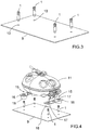
- Fig. 3 shows a schematic three-dimensional view of a base plate 9 for a refrigerant compressor with four screw pins 1 to be installed, see the arrows below the screw pins 1.
- the base plate 9 has four threaded holes 10 and the four screw pins 1 will be screwed into the base plate with their respective threaded portions 3.
- the middle portions 4, the neck portions 5 and the head portions 6 of the screw pins 1 protrude from the top of the base plate 9.
- FIG. 4 where a refrigerant compressor housing 11 to be installed is depicted above the base plate 9.
- the refrigerant compressor housing has two legs 15.
- Each leg 15 has a plate 16, which plates 16 here are oriented parallel to the base plate 9.
- Each plate 16 has two circular openings 17.
- Each opening 17 is surrounded by a cylindrical sleeve 18, here in the form of a rubber grommet, which in mounting position is situated below the plate 16.
- the height of the sleeve 18 and the thickness of the plate 16 together correspond to the height of the middle portion 4 of the screw pin 1.
- the flaps 13,14 are used as grip or handles to move the clip 2.
- First flap 13 is used to press the first slot 7 of the clip 2 around the first screw pin 1, see Fig. 5 .
- the second flap 14 is used to to press the second slot 8 of the clip 2 around the second screw pin 1, see Fig. 6 .
- the clip 2 has its first slot 7 around the neck portion 5 of the first screw pin 1 and the second slot 8 around the neck portion 5 of the second screw pin 1. That means that the neck portion 5 of the bottom screw pin 1 in Fig. 7 is within the circular arcs of the second slot 8 of clip 2, thus the clip 2 is locked and the housing 11 is pressed against the base plate 9.
- a second clip which is not identical to the clip 2 in Fig 2 but which is its mirror image.
- This second clip can be constructed by a mirror plane which is normal to the plane of projection of Fig. 2 and which runs from left to right in Fig. 2 . So the second clip has the entrance of the second slot 8 at the top (and not at the bottom as clip 2 in Fig. 2 ) .
- This second clip can be inserted with its first slot 7 around the neck portion 5 of top left screw pin 1 in Fig. 4 , then the second clip can be turned right and the second slot 8 will be pressed around the neck portion 5 of bottom left screw pin 1 in Fig. 4 from the left so that the neck portion 5 of the bottom left screw pin 1 of Fig. 4 is within the circular arcs of the second slot 8 of the second clip.
- the clip 2 and the second clip can be mounted manually at the same time, the clip 2 from the right (e.g. with the right hand), as depicted in Fig. 5-7 , and the second clip from the left (e.g. with the left hand), with reference to Fig. 4 .
- operation time for mounting and work load can be reduced.
Landscapes
- Engineering & Computer Science (AREA)
- Mechanical Engineering (AREA)
- General Engineering & Computer Science (AREA)
- Compressor (AREA)
Description
- The present invention relates to a system for mounting a refrigerant compressor housing to a base plate having threaded holes, the system comprising at least two screw pins and one clip to connect the two screw pins.
- The system according to the invention can be used for refrigerant compressors which are situated in a compressor housing, e.g. consisting of two parts, namely a compressor housing base and a compressor housing cover. Such a compressor housing hermetically encloses a cylinder housing and a drive assembly, the refrigerant compressor further comprising a cylinder and a piston which are arranged inside the cylinder housing, said piston being drivable by the drive assembly, in order to move back and forth in the cylinder for compressing a refrigerant.
- For mounting a compressor housing in a refrigerator, the compressor housing often first has to be fixed to a base plate. Normally the compressor housing has some kind of legs with openings in the legs for that purpose. There are several methods to quickly and simply mount the compressor housing to the base plate. One method is to use screws with heads larger than the openings of the legs of the compressor housing and to simply screw the legs to the base plate which has corresponding threaded holes.
- Another possibility is to use bolts which press the legs to one side of the base plate and which bolts are secured on the other side of the base plate by using clips. Such clips are only snapped on the bolts which is faster than screwing screws into the base plate. However, during production access to both sides of the base plate is necessary.
-
CN 104 279 814 A shows a system for mounting a refrigerant compressor housing to a base plate having holes, comprising at least two pins, but no screw pins, and one clip to connect the two pins. Each pin, as seen in its longitudinal direction, has a middle portion to be inserted into a respective opening of a refrigerant compressor housing, the middle portion being followed by a neck portion having a smaller diameter than the middle portion, the neck portion being followed by a head portion having a larger diameter than the neck portion. The elongate clip has one slot in each of its two end portions, the first slot being oriented in longitudinal direction of the clip, the second slot being oriented normal to the longitudinal direction of the clip. -
CN 203 035 489 U andCN 102 947 656 A disclose clips with slots which are not oriented normal to each other. - It is thus an objective of the present invention to provide a system for mounting a refrigerant compressor housing to a base plate which base plate already has threaded holes in it but which system does not need access to both sides of the base plate.
- According to the invention a system for mounting a refrigerant compressor housing to a base plate having threaded holes is provided, the system comprising at least two screw pins and one clip to connect the two screw pins, whereas each screw pin, as seen in its longitudinal direction, has a threaded portion for screwing the screw pin into a threaded hole of a base plate, the threaded portion being followed by a middle portion to be inserted into a respective opening of a refrigerant compressor housing, the middle portion being followed by a neck portion having a smaller diameter than the middle portion, the neck portion being followed by a head portion, the head portion having a larger diameter than the neck portion, the system being further characterized in that the elongate clip has one slot in each of its two end portions, the first slot having a width equal to the diameter of the neck portion of the screw pin and being oriented in longitudinal direction of the clip, the second slot narrowing to a width smaller than the diameter of the neck portion of the screw pin and then enlarging to a diameter equal to the diameter of the neck portion and the second slot being oriented normal to the longitudinal direction of the clip.
- Using this system one can screw two screw pins into the base plate from the top side of the base plate, each screw pin into one threaded hole. Then the compressor housing is put onto the base plate from the top side of the base plate so that the screw pins protrude through the openings of the legs of the compressor housing. Then - again working on the top side of the base plate - the neck of the first screw pin is inserted into the first slot of the clip. The clip is turned around the neck of the first screw pin - in a plane parallel to the base plate - so that the neck of the second screw pin is inserted into the second slot of the clip and by pressing the clip further against the neck of the second screw pin the neck passes the narrowing portion of the second slot and is securely fixed in the second slot. As a result the legs of the compressor housing are held in place, that is, they are pressed against the base plate by the clip.
- In order to secure the clip against lateral displacement, that is displacement parallel to the base plate when mounted on the base plate, in a preferred embodiment of the present invention, it is provided that the enlarging portion of the second slot is again followed by a second narrowing portion which portions correspond to the outer dimensions of the neck portion of the screw pin in order to hold the neck portion within the enlarging portion and the second narrowing portion of the second slot.
- A preferred embodiment of the invention provides that the clip is made of sheet metal. Thus the clip or clips can be produced easily and nevertheless have the necessary stability.
- In order to provide a grip for manually mounting the clip, it is provided in a preferred embodiment of the present invention that around the second slot the clip has at least one flap which is formed from the sheet metal of the clip by folding the sheet metal normal to the plane of the clip.
- In this case a first flap can be oriented parallel to the second slot. A second flap can be oriented normal to the second slot and facing away from the entrance of the second slot.
- In a preferred embodiment of the present invention it is provided that the system comprises four screw pins and two clips and that the first clip is the mirror image of the second clip. Thus it is possible to mount one clip from the left of the compressor housing and one clip from the right of the compressor housing.
- In a preferred embodiment of the present invention it is provided that the head portion of the screw pin has indentations or lobes in order to allow the screw pin to be screwed in by hand or with a tool.
- Once the system is mounted the system in a preferred embodiment further comprises a refrigerant compressor housing and a base plate having four threaded holes, four screw pins being screwed into the base plate, the middle portion of each screw pin being in a respective opening of a leg of the refrigerant compressor housing, the leg of the refrigerant compressor housing contacting the base plate, the first clip having its first slot around the neck portion of a first screw pin and the second slot around the neck portion of a second screw pin, the second clip having its first slot around the neck portion of a third screw pin and the second slot around the neck portion of a fourth screw pin.
- The invention will be explained in closer detail by reference to a preferred embodiment, with
- Fig. 1
- showing a schematic side view of a screw pin according to the present invention
- Fig. 2
- showing a schematic top view of a clip according to the present invention,
- Fig. 3
- showing a schematic three-dimensional view of a base plate for a refrigerant compressor with screw pins to be installed,
- Fig. 4
- showing a schematic three-dimensional view of the base plate of
Fig. 3 with a refrigerant compressor housing to be installed, - Fig. 5
- showing a schematic three-dimensional view of one leg of the refrigerant compressor housing of
Fig. 4 mounted on the base plate and a clip to be inserted, - Fig. 6
- showing the leg of
Fig. 5 with the clip inserted into one screw pin, - Fig. 7
- showing the leg of
Fig. 5 and 6 with the clip inserted into both screw pins. -
Fig. 1 shows ascrew pin 1 according to the present invention. When seen in its longitudinal direction, that is from bottom to top inFig. 1 , thescrew pin 1 has at its bottom a threadedportion 3 for screwing the screw pin into a threaded hole 10 (seeFig. 3 ) of a base plate 9 (seeFig. 3 ). The threadedportion 3 is followed by a middle portion 4 which can be inserted into a respective opening of a refrigerant compressor housing 11 (seeFig. 4 ). The middle portion 4 here has cylindrical form and has a larger diameter than the threadedportion 3. The middle portion 4 is followed by aneck portion 5 having a smaller diameter than the middle portion 4. The neck portion 4 here also has cylindrical form. Theneck portion 5 connects to the middle portion 4 via a tapered portion. Theneck portion 5 is followed by a head portion 6, which again has a larger diameter than theneck portion 5. The head portion 6 of thescrew pin 1 here haslobes 12 in order to allow thescrew pin 1 to be screwed in by hand or with a tool. - The
screw pin 1 is made of metal. -
Fig. 2 shows a schematic top view of aclip 2 according to the present invention. Theclip 2 is elongate and has oneslot first slot 7 has a width equal to the diameter of theneck portion 5 of thescrew pin 1 and is oriented in longitudinal direction of theclip 2, that is from left to right inFig. 2 . Thesecond slot 8 has its entrance on the bottom ofFig. 2 . Thesecond slot 8 narrows from its entrance to a width smaller than the diameter of theneck portion 5 of thescrew pin 1 and then enlarges to a diameter equal to the diameter of theneck portion 5. This enlarging portion of thesecond slot 8 is again followed by a second narrowing portion. The enlarging portion and the second narrowing portion correspond to the outer dimensions of theneck portion 5 of thescrew pin 1 in order to hold theneck portion 5 within the enlarging portion and the second narrowing portion of thesecond slot 8. The enlarging portion and the second narrowing portion here have the form of a circular arc. The circular arcs correspond to theneck portion 5 which has cylindrical form. - The
second slot 8 is oriented normal to the longitudinal direction of theclip 2, that is from bottom to top in the drawing ofFig. 2 . - The
clip 2 is made of sheet metal. - In order to provide a grip for manually mounting the
clip 2 theclip 2 has twoflaps second slot 8 which are formed from the sheet metal of theclip 2 by folding the sheet metal normal to the plane of theclip 2. Thefirst flap 13 is oriented parallel to thesecond slot 8. Thesecond flap 14 is oriented normal to thesecond slot 8 and facing away from the entrance of thesecond slot 8. -
Fig. 3 shows a schematic three-dimensional view of abase plate 9 for a refrigerant compressor with fourscrew pins 1 to be installed, see the arrows below the screw pins 1. Thebase plate 9 has four threadedholes 10 and the fourscrew pins 1 will be screwed into the base plate with their respective threadedportions 3. The middle portions 4, theneck portions 5 and the head portions 6 of the screw pins 1 protrude from the top of thebase plate 9. - This can be seen in
Fig. 4 , where arefrigerant compressor housing 11 to be installed is depicted above thebase plate 9. The refrigerant compressor housing has twolegs 15. Eachleg 15 has aplate 16, whichplates 16 here are oriented parallel to thebase plate 9. Eachplate 16 has twocircular openings 17. Eachopening 17 is surrounded by acylindrical sleeve 18, here in the form of a rubber grommet, which in mounting position is situated below theplate 16. The height of thesleeve 18 and the thickness of theplate 16 together correspond to the height of the middle portion 4 of thescrew pin 1. Thus only theneck portion 5 and the head portion 6 of the screw pins 1 protrude out of theleg 15 once thehousing 11 is mounted on thebase plate 9, that is, once thesleeves 18 are put around the screw pins 1 and contact and stand on thebase plate 9. The inner diameter of thesleeves 18 is dimensioned according to the diameter of the middle portions 4 of the screw pins 1 so that thehousing 11 is secured against lateral movement (=parallel to the base plate 9) by the screw pins 1. - Next the
clip 2 ofFig. 2 is inserted with itsfirst slot 7 into theneck portion 5 of a first screw pin, namely the one near the top right corner of thebase plate 9 inFig. 4 . This is depicted inFig. 5 . - In
Fig. 6 one can see that thefirst slot 7 ofclip 2 is inserted or put around theneck portion 5 of thefirst screw pin 1 until the end of thefirst slot 7. Then theclip 2 is rotated around thefirst screw pin 1 so that thesecond slot 8 reaches thesecond screw pin 1, the one in the bottom right corner ofFig. 4 . The distance between the end of thefirst slot 7 and thesecond slot 8 equals the distance of the twoscrew pins 1 inFig. 5-7 . - The
flaps clip 2.First flap 13 is used to press thefirst slot 7 of theclip 2 around thefirst screw pin 1, seeFig. 5 . Thesecond flap 14 is used to to press thesecond slot 8 of theclip 2 around thesecond screw pin 1, seeFig. 6 . - In
Fig. 7 , theclip 2 has itsfirst slot 7 around theneck portion 5 of thefirst screw pin 1 and thesecond slot 8 around theneck portion 5 of thesecond screw pin 1. That means that theneck portion 5 of thebottom screw pin 1 inFig. 7 is within the circular arcs of thesecond slot 8 ofclip 2, thus theclip 2 is locked and thehousing 11 is pressed against thebase plate 9. - In order to mount also the
left leg 15 of thehousing 11 inFig. 4 , one needs a second clip which is not identical to theclip 2 inFig 2 but which is its mirror image. This second clip can be constructed by a mirror plane which is normal to the plane of projection ofFig. 2 and which runs from left to right inFig. 2 . So the second clip has the entrance of thesecond slot 8 at the top (and not at the bottom asclip 2 inFig. 2 ) . - This second clip can be inserted with its
first slot 7 around theneck portion 5 of topleft screw pin 1 inFig. 4 , then the second clip can be turned right and thesecond slot 8 will be pressed around theneck portion 5 of bottomleft screw pin 1 inFig. 4 from the left so that theneck portion 5 of the bottomleft screw pin 1 ofFig. 4 is within the circular arcs of thesecond slot 8 of the second clip. - With the present invention it is possible to us a snap on mounting technique also for
base plates 9 with screw holes. Although snap on clips for single pins are known, these clips for single pins have to be mounted on the back side of thebase plate 9 which includes one more mounting step for turning around thebase plate 9. And more space on the back side of thebase plate 9 is needed which consumes valuable space of a refrigerator. - With the present invention it is possible to work only on the top side of the
base plate 9 when mounting thehousing 11. No space on the back side of thebase plate 9 is wasted. Theclip 2 and the second clip can be mounted manually at the same time, theclip 2 from the right (e.g. with the right hand), as depicted inFig. 5-7 , and the second clip from the left (e.g. with the left hand), with reference toFig. 4 . Thus operation time for mounting and work load can be reduced. - No tools are needed to snap the
clips 2 into the locking position. So even if thehousing 11 is very large and/or other objects like controller boxes or tubes relating to the compressor are around thehousing 11, it is normally possible to insert theclip 2 with itsfirst slot 7 into the screw pins 1 at the top of thebase plate 9, assuming that the assembler sits in front of thebase plate 9 as inFig. 4 . -
- 1
- screw pin
- 2
- clip
- 3
- threaded portion
- 4
- middle portion
- 5
- neck portion
- 6
- head portion
- 7
- first slot
- 8
- second slot
- 9
- base plate
- 10
- threaded hole
- 11
- refrigerant compressor housing (housing)
- 12
- lobe
- 13
- first flap
- 14
- second flap
- 15
- leg
- 16
- plate
- 17
- opening of
plate 16 - 18
- sleeve (grommet)
Claims (9)
- System for mounting a refrigerant compressor housing (11) to a base plate (9) having threaded holes (10), the system comprising at least two screw pins (1) and one clip (2) to connect the two screw pins, wherein each screw pin (1), as seen in its longitudinal direction, has a threaded portion (3) for screwing the screw pin (1) into a threaded hole (10) of a base plate (9), the threaded portion (3) being followed by a middle portion (4) to be inserted into a respective opening (17) of a refrigerant compressor housing (11), the middle portion (4) being followed by a neck portion (5) having a smaller diameter than the middle portion (4), the neck portion (5) being followed by a head portion (6), the head portion (6) having a larger diameter than the neck portion (5), wherein the elongate clip (2) has one slot (7,8) in each of its two end portions, the first slot (7) having a width equal to the diameter of the neck portion (5) of the screw pin (1) and being oriented in longitudinal direction of the clip (2), the second slot (8) narrowing to a width smaller than the diameter of the neck portion (5) of the screw pin (1) and then enlarging to a diameter equal to the diameter of the neck portion (5) and the second slot (8) being oriented normal to the longitudinal direction of the clip (2).
- System according to claim 1, characterised in that the enlarging portion of the second slot (8) is again followed by a second narrowing portion which portions correspond to the outer dimensions of the neck portion (5) of the screw pin (1) in order to hold the neck portion (5) within the enlarging portion and the second narrowing portion of the second slot (8).
- System according to claim 1, characterised in that the clip (2) is made of sheet metal.
- System according to claim 3, characterised in that around the second slot (8) the clip (2) has at least one flap (13,14) which is formed from the sheet metal of the clip (2) by folding the sheet metal normal to the plane of the clip (2).
- System according to claim 4, characterised in that a first flap (13) is oriented parallel to the second slot (8).
- System according to claim 5, characterised in that a second flap (14) is oriented normal to the second slot (8) and facing away from the entrance of the second slot (8).
- System according to claim 1, characterised in that it comprises four screw pins (1) and two clips (2) and that the first clip is the mirror image of the second clip.
- System according to claim 1, characterised in that the head portion (6) of the screw pin (1) has indentations or lobes (12) in order to allow the screw pin (1) to be screwed in by hand or with a tool.
- System according to claim 1, characterised in that the system further comprises a refrigerant compressor housing (11) and a base plate (9) having four threaded holes (10), four screw pins (1) being screwed into the base plate (9), the middle portion (4) of each screw pin (1) being in a respective opening (17) of a leg (15) of the refrigerant compressor housing (11), the leg (15) of the refrigerant compressor housing (11) contacting the base plate (9), the first clip (2) having its first slot around the neck portion (5) of a first screw pin and the second slot (7) around the neck portion (5) of a second screw pin (1), the second clip having its first slot (7) around the neck portion (5) of a third screw pin (1) and the second slot (8) around the neck portion of a fourth screw pin (1).
Applications Claiming Priority (2)
| Application Number | Priority Date | Filing Date | Title |
|---|---|---|---|
| CN201620455294.1U CN205689383U (en) | 2016-05-18 | 2016-05-18 | Refrigeration compressor shell is installed to the system with the substrate in threaded hole |
| PCT/CN2017/084320 WO2017198123A1 (en) | 2016-05-18 | 2017-05-15 | System for mounting a refrigerant compressor housing to a base plate |
Publications (3)
| Publication Number | Publication Date |
|---|---|
| EP3458716A1 EP3458716A1 (en) | 2019-03-27 |
| EP3458716A4 EP3458716A4 (en) | 2019-05-29 |
| EP3458716B1 true EP3458716B1 (en) | 2020-07-15 |
Family
ID=57263023
Family Applications (1)
| Application Number | Title | Priority Date | Filing Date |
|---|---|---|---|
| EP17798686.6A Active EP3458716B1 (en) | 2016-05-18 | 2017-05-15 | System for mounting a refrigerant compressor housing to a base plate |
Country Status (4)
| Country | Link |
|---|---|
| US (1) | US10859079B2 (en) |
| EP (1) | EP3458716B1 (en) |
| CN (1) | CN205689383U (en) |
| WO (1) | WO2017198123A1 (en) |
Families Citing this family (4)
| Publication number | Priority date | Publication date | Assignee | Title |
|---|---|---|---|---|
| CN205689383U (en) | 2016-05-18 | 2016-11-16 | 思科普压缩机(天津)有限公司 | Refrigeration compressor shell is installed to the system with the substrate in threaded hole |
| US10823167B2 (en) * | 2019-01-31 | 2020-11-03 | Wilden Pump And Engineering Llc | Pump assembly |
| EP4414525B1 (en) * | 2023-02-07 | 2025-08-06 | Gatemaster Ltd | Gate fastener with locking pin and method for securing a double gate with such a gate fastener |
| CN116465136B (en) * | 2023-05-29 | 2026-01-09 | 青岛海容商用冷链股份有限公司 | Round Barrel Cabinet and its Installation Method |
Family Cites Families (16)
| Publication number | Priority date | Publication date | Assignee | Title |
|---|---|---|---|---|
| US6067700A (en) * | 1997-06-24 | 2000-05-30 | Rheem Manufacturing, Company | Prestressed compressor mount installation methods |
| US6354558B1 (en) * | 1998-11-20 | 2002-03-12 | Carrier Corporation | Compressor mounting |
| KR20070099814A (en) * | 2006-04-05 | 2007-10-10 | 삼성광주전자 주식회사 | Compressor Fixing Bracket |
| DE102006020506B4 (en) * | 2006-04-22 | 2014-05-15 | Rittal Gmbh & Co. Kg | cooling unit |
| US20090272872A1 (en) * | 2008-04-30 | 2009-11-05 | Hoffman Loren D | Mounting assembly to secure a grommet to a compressor foot including dimpled slot |
| DE102008033764B4 (en) * | 2008-07-18 | 2017-04-06 | Secop Gmbh | Hermetically sealed refrigerant compressor |
| DE102010002045A1 (en) | 2010-02-17 | 2011-08-18 | BSH Bosch und Siemens Hausgeräte GmbH, 81739 | Refrigerating appliance with a fastening device for a compressor and method for mounting a compressor |
| JP2013024069A (en) | 2011-07-19 | 2013-02-04 | Panasonic Corp | Hermetic type electric compressor |
| CN203035489U (en) * | 2012-12-31 | 2013-07-03 | 泰州乐金电子冷机有限公司 | Compressor fixing device |
| CN104279814B (en) * | 2013-07-11 | 2017-11-21 | 泰州乐金电子冷机有限公司 | The fixing device of refrigeration plant compressor |
| CN203570527U (en) | 2013-11-01 | 2014-04-30 | 湖南江麓重工科技有限公司 | Ai-conditioner compressor support |
| DE102014206718A1 (en) * | 2014-04-08 | 2015-10-08 | BSH Hausgeräte GmbH | household appliance |
| CN204774499U (en) | 2015-06-08 | 2015-11-18 | 南京金龙新能源汽车研究院有限公司 | Novel air condition compressor installing support |
| US10359225B2 (en) * | 2016-03-07 | 2019-07-23 | Whirlpool Corporation | Refrigerator vibration isolating compressor mount |
| CN205689383U (en) | 2016-05-18 | 2016-11-16 | 思科普压缩机(天津)有限公司 | Refrigeration compressor shell is installed to the system with the substrate in threaded hole |
| KR101865517B1 (en) * | 2017-10-24 | 2018-06-07 | 엘지전자 주식회사 | Reciprocating compressor and a method manufacturing the same |
-
2016
- 2016-05-18 CN CN201620455294.1U patent/CN205689383U/en not_active Expired - Lifetime
-
2017
- 2017-05-15 EP EP17798686.6A patent/EP3458716B1/en active Active
- 2017-05-15 US US16/302,507 patent/US10859079B2/en active Active
- 2017-05-15 WO PCT/CN2017/084320 patent/WO2017198123A1/en not_active Ceased
Non-Patent Citations (1)
| Title |
|---|
| None * |
Also Published As
| Publication number | Publication date |
|---|---|
| CN205689383U (en) | 2016-11-16 |
| WO2017198123A1 (en) | 2017-11-23 |
| US10859079B2 (en) | 2020-12-08 |
| EP3458716A4 (en) | 2019-05-29 |
| US20190170132A1 (en) | 2019-06-06 |
| EP3458716A1 (en) | 2019-03-27 |
Similar Documents
| Publication | Publication Date | Title |
|---|---|---|
| US10859079B2 (en) | System for mounting a refrigerant compressor housing to a base plate | |
| US9827663B2 (en) | Hand tool frame | |
| US20130170895A1 (en) | Floating fastener with expanded application flexibility | |
| US6874984B2 (en) | Expansion bolt having internal spherical member and rear driving bolt | |
| GB2371976A (en) | Mounting for a towel rail | |
| EP3424644B1 (en) | Ball-and-socket joint puller | |
| US20180306232A1 (en) | Precision holding and locating pin | |
| US7331104B2 (en) | Device for the assembly of standard elements intended for the creation of precision mechanical structures | |
| GB2255036A (en) | Punch press with several punch pressing units. | |
| JP2014129843A (en) | Attachment structure of cylinder | |
| KR20200005095A (en) | Connecting Apparatus for Plate Type Member | |
| WO2001007210A1 (en) | Multi-socket wrench | |
| US6442847B1 (en) | Portable punching machine | |
| US20060117916A1 (en) | Sleeve device with stepped structure | |
| KR20190069098A (en) | A driver bit capable of mounting bolts and nuts of various sizes and an electric screwdriver with the same | |
| CA2596630A1 (en) | Storage system with adjustable pole | |
| US9970592B2 (en) | Detachable mounting device | |
| JP2008501542A (en) | Tool holder assembly | |
| US20050050642A1 (en) | Chain detaching handle tool | |
| US20160107280A1 (en) | Press mechanism | |
| KR20190107471A (en) | Kit type vise | |
| KR102148101B1 (en) | Driver | |
| JP6321480B2 (en) | Offset type floating nut | |
| CN109702459B (en) | Combined type crimping block of crimping machine | |
| CN222903989U (en) | Adjustable workbench |
Legal Events
| Date | Code | Title | Description |
|---|---|---|---|
| STAA | Information on the status of an ep patent application or granted ep patent |
Free format text: STATUS: THE INTERNATIONAL PUBLICATION HAS BEEN MADE |
|
| PUAI | Public reference made under article 153(3) epc to a published international application that has entered the european phase |
Free format text: ORIGINAL CODE: 0009012 |
|
| STAA | Information on the status of an ep patent application or granted ep patent |
Free format text: STATUS: REQUEST FOR EXAMINATION WAS MADE |
|
| 17P | Request for examination filed |
Effective date: 20181206 |
|
| AK | Designated contracting states |
Kind code of ref document: A1 Designated state(s): AL AT BE BG CH CY CZ DE DK EE ES FI FR GB GR HR HU IE IS IT LI LT LU LV MC MK MT NL NO PL PT RO RS SE SI SK SM TR |
|
| AX | Request for extension of the european patent |
Extension state: BA ME |
|
| A4 | Supplementary search report drawn up and despatched |
Effective date: 20190429 |
|
| RIC1 | Information provided on ipc code assigned before grant |
Ipc: F04B 39/00 20060101AFI20190423BHEP Ipc: F04B 39/12 20060101ALI20190423BHEP Ipc: F04B 39/14 20060101ALI20190423BHEP |
|
| DAV | Request for validation of the european patent (deleted) | ||
| DAX | Request for extension of the european patent (deleted) | ||
| GRAP | Despatch of communication of intention to grant a patent |
Free format text: ORIGINAL CODE: EPIDOSNIGR1 |
|
| STAA | Information on the status of an ep patent application or granted ep patent |
Free format text: STATUS: GRANT OF PATENT IS INTENDED |
|
| RIC1 | Information provided on ipc code assigned before grant |
Ipc: F04B 39/00 20060101AFI20200120BHEP Ipc: F04B 39/12 20060101ALI20200120BHEP Ipc: F04B 39/14 20060101ALI20200120BHEP |
|
| INTG | Intention to grant announced |
Effective date: 20200207 |
|
| GRAS | Grant fee paid |
Free format text: ORIGINAL CODE: EPIDOSNIGR3 |
|
| GRAA | (expected) grant |
Free format text: ORIGINAL CODE: 0009210 |
|
| STAA | Information on the status of an ep patent application or granted ep patent |
Free format text: STATUS: THE PATENT HAS BEEN GRANTED |
|
| AK | Designated contracting states |
Kind code of ref document: B1 Designated state(s): AL AT BE BG CH CY CZ DE DK EE ES FI FR GB GR HR HU IE IS IT LI LT LU LV MC MK MT NL NO PL PT RO RS SE SI SK SM TR |
|
| REG | Reference to a national code |
Ref country code: CH Ref legal event code: EP Ref country code: GB Ref legal event code: FG4D |
|
| REG | Reference to a national code |
Ref country code: IE Ref legal event code: FG4D |
|
| REG | Reference to a national code |
Ref country code: DE Ref legal event code: R096 Ref document number: 602017019952 Country of ref document: DE |
|
| REG | Reference to a national code |
Ref country code: AT Ref legal event code: REF Ref document number: 1291316 Country of ref document: AT Kind code of ref document: T Effective date: 20200815 |
|
| REG | Reference to a national code |
Ref country code: DE Ref legal event code: R082 Ref document number: 602017019952 Country of ref document: DE Representative=s name: KUHNEN & WACKER PATENT- UND RECHTSANWALTSBUERO, DE Ref country code: DE Ref legal event code: R081 Ref document number: 602017019952 Country of ref document: DE Owner name: SECOP COMPRESSORS (TIANJIN) CO., LTD., CN Free format text: FORMER OWNER: NIDEC COMPRESSORS (TIANJIN) CO., LTD., TIANJIN, CN |
|
| REG | Reference to a national code |
Ref country code: SK Ref legal event code: T3 Ref document number: E 35122 Country of ref document: SK |
|
| REG | Reference to a national code |
Ref country code: LT Ref legal event code: MG4D |
|
| REG | Reference to a national code |
Ref country code: AT Ref legal event code: MK05 Ref document number: 1291316 Country of ref document: AT Kind code of ref document: T Effective date: 20200715 |
|
| REG | Reference to a national code |
Ref country code: NL Ref legal event code: MP Effective date: 20200715 |
|
| PG25 | Lapsed in a contracting state [announced via postgrant information from national office to epo] |
Ref country code: NO Free format text: LAPSE BECAUSE OF FAILURE TO SUBMIT A TRANSLATION OF THE DESCRIPTION OR TO PAY THE FEE WITHIN THE PRESCRIBED TIME-LIMIT Effective date: 20201015 Ref country code: GR Free format text: LAPSE BECAUSE OF FAILURE TO SUBMIT A TRANSLATION OF THE DESCRIPTION OR TO PAY THE FEE WITHIN THE PRESCRIBED TIME-LIMIT Effective date: 20201016 Ref country code: ES Free format text: LAPSE BECAUSE OF FAILURE TO SUBMIT A TRANSLATION OF THE DESCRIPTION OR TO PAY THE FEE WITHIN THE PRESCRIBED TIME-LIMIT Effective date: 20200715 Ref country code: HR Free format text: LAPSE BECAUSE OF FAILURE TO SUBMIT A TRANSLATION OF THE DESCRIPTION OR TO PAY THE FEE WITHIN THE PRESCRIBED TIME-LIMIT Effective date: 20200715 Ref country code: SE Free format text: LAPSE BECAUSE OF FAILURE TO SUBMIT A TRANSLATION OF THE DESCRIPTION OR TO PAY THE FEE WITHIN THE PRESCRIBED TIME-LIMIT Effective date: 20200715 Ref country code: FI Free format text: LAPSE BECAUSE OF FAILURE TO SUBMIT A TRANSLATION OF THE DESCRIPTION OR TO PAY THE FEE WITHIN THE PRESCRIBED TIME-LIMIT Effective date: 20200715 Ref country code: LT Free format text: LAPSE BECAUSE OF FAILURE TO SUBMIT A TRANSLATION OF THE DESCRIPTION OR TO PAY THE FEE WITHIN THE PRESCRIBED TIME-LIMIT Effective date: 20200715 Ref country code: AT Free format text: LAPSE BECAUSE OF FAILURE TO SUBMIT A TRANSLATION OF THE DESCRIPTION OR TO PAY THE FEE WITHIN THE PRESCRIBED TIME-LIMIT Effective date: 20200715 Ref country code: PT Free format text: LAPSE BECAUSE OF FAILURE TO SUBMIT A TRANSLATION OF THE DESCRIPTION OR TO PAY THE FEE WITHIN THE PRESCRIBED TIME-LIMIT Effective date: 20201116 Ref country code: BG Free format text: LAPSE BECAUSE OF FAILURE TO SUBMIT A TRANSLATION OF THE DESCRIPTION OR TO PAY THE FEE WITHIN THE PRESCRIBED TIME-LIMIT Effective date: 20201015 |
|
| PG25 | Lapsed in a contracting state [announced via postgrant information from national office to epo] |
Ref country code: RS Free format text: LAPSE BECAUSE OF FAILURE TO SUBMIT A TRANSLATION OF THE DESCRIPTION OR TO PAY THE FEE WITHIN THE PRESCRIBED TIME-LIMIT Effective date: 20200715 Ref country code: PL Free format text: LAPSE BECAUSE OF FAILURE TO SUBMIT A TRANSLATION OF THE DESCRIPTION OR TO PAY THE FEE WITHIN THE PRESCRIBED TIME-LIMIT Effective date: 20200715 Ref country code: LV Free format text: LAPSE BECAUSE OF FAILURE TO SUBMIT A TRANSLATION OF THE DESCRIPTION OR TO PAY THE FEE WITHIN THE PRESCRIBED TIME-LIMIT Effective date: 20200715 Ref country code: IS Free format text: LAPSE BECAUSE OF FAILURE TO SUBMIT A TRANSLATION OF THE DESCRIPTION OR TO PAY THE FEE WITHIN THE PRESCRIBED TIME-LIMIT Effective date: 20201115 |
|
| RAP2 | Party data changed (patent owner data changed or rights of a patent transferred) |
Owner name: SECOP COMPRESSORS (TIANJIN) CO., LTD. |
|
| PG25 | Lapsed in a contracting state [announced via postgrant information from national office to epo] |
Ref country code: NL Free format text: LAPSE BECAUSE OF FAILURE TO SUBMIT A TRANSLATION OF THE DESCRIPTION OR TO PAY THE FEE WITHIN THE PRESCRIBED TIME-LIMIT Effective date: 20200715 |
|
| REG | Reference to a national code |
Ref country code: DE Ref legal event code: R097 Ref document number: 602017019952 Country of ref document: DE |
|
| PG25 | Lapsed in a contracting state [announced via postgrant information from national office to epo] |
Ref country code: SM Free format text: LAPSE BECAUSE OF FAILURE TO SUBMIT A TRANSLATION OF THE DESCRIPTION OR TO PAY THE FEE WITHIN THE PRESCRIBED TIME-LIMIT Effective date: 20200715 Ref country code: EE Free format text: LAPSE BECAUSE OF FAILURE TO SUBMIT A TRANSLATION OF THE DESCRIPTION OR TO PAY THE FEE WITHIN THE PRESCRIBED TIME-LIMIT Effective date: 20200715 Ref country code: RO Free format text: LAPSE BECAUSE OF FAILURE TO SUBMIT A TRANSLATION OF THE DESCRIPTION OR TO PAY THE FEE WITHIN THE PRESCRIBED TIME-LIMIT Effective date: 20200715 Ref country code: CZ Free format text: LAPSE BECAUSE OF FAILURE TO SUBMIT A TRANSLATION OF THE DESCRIPTION OR TO PAY THE FEE WITHIN THE PRESCRIBED TIME-LIMIT Effective date: 20200715 Ref country code: DK Free format text: LAPSE BECAUSE OF FAILURE TO SUBMIT A TRANSLATION OF THE DESCRIPTION OR TO PAY THE FEE WITHIN THE PRESCRIBED TIME-LIMIT Effective date: 20200715 |
|
| PLBE | No opposition filed within time limit |
Free format text: ORIGINAL CODE: 0009261 |
|
| STAA | Information on the status of an ep patent application or granted ep patent |
Free format text: STATUS: NO OPPOSITION FILED WITHIN TIME LIMIT |
|
| PG25 | Lapsed in a contracting state [announced via postgrant information from national office to epo] |
Ref country code: AL Free format text: LAPSE BECAUSE OF FAILURE TO SUBMIT A TRANSLATION OF THE DESCRIPTION OR TO PAY THE FEE WITHIN THE PRESCRIBED TIME-LIMIT Effective date: 20200715 |
|
| 26N | No opposition filed |
Effective date: 20210416 |
|
| PG25 | Lapsed in a contracting state [announced via postgrant information from national office to epo] |
Ref country code: SI Free format text: LAPSE BECAUSE OF FAILURE TO SUBMIT A TRANSLATION OF THE DESCRIPTION OR TO PAY THE FEE WITHIN THE PRESCRIBED TIME-LIMIT Effective date: 20200715 |
|
| REG | Reference to a national code |
Ref country code: CH Ref legal event code: PL |
|
| GBPC | Gb: european patent ceased through non-payment of renewal fee |
Effective date: 20210515 |
|
| PG25 | Lapsed in a contracting state [announced via postgrant information from national office to epo] |
Ref country code: LU Free format text: LAPSE BECAUSE OF NON-PAYMENT OF DUE FEES Effective date: 20210515 Ref country code: MC Free format text: LAPSE BECAUSE OF FAILURE TO SUBMIT A TRANSLATION OF THE DESCRIPTION OR TO PAY THE FEE WITHIN THE PRESCRIBED TIME-LIMIT Effective date: 20200715 Ref country code: LI Free format text: LAPSE BECAUSE OF NON-PAYMENT OF DUE FEES Effective date: 20210531 Ref country code: CH Free format text: LAPSE BECAUSE OF NON-PAYMENT OF DUE FEES Effective date: 20210531 |
|
| REG | Reference to a national code |
Ref country code: BE Ref legal event code: MM Effective date: 20210531 |
|
| PG25 | Lapsed in a contracting state [announced via postgrant information from national office to epo] |
Ref country code: IE Free format text: LAPSE BECAUSE OF NON-PAYMENT OF DUE FEES Effective date: 20210515 Ref country code: GB Free format text: LAPSE BECAUSE OF NON-PAYMENT OF DUE FEES Effective date: 20210515 |
|
| PG25 | Lapsed in a contracting state [announced via postgrant information from national office to epo] |
Ref country code: FR Free format text: LAPSE BECAUSE OF NON-PAYMENT OF DUE FEES Effective date: 20210531 |
|
| PG25 | Lapsed in a contracting state [announced via postgrant information from national office to epo] |
Ref country code: BE Free format text: LAPSE BECAUSE OF NON-PAYMENT OF DUE FEES Effective date: 20210531 |
|
| P01 | Opt-out of the competence of the unified patent court (upc) registered |
Effective date: 20230517 |
|
| PG25 | Lapsed in a contracting state [announced via postgrant information from national office to epo] |
Ref country code: CY Free format text: LAPSE BECAUSE OF FAILURE TO SUBMIT A TRANSLATION OF THE DESCRIPTION OR TO PAY THE FEE WITHIN THE PRESCRIBED TIME-LIMIT Effective date: 20200715 |
|
| PG25 | Lapsed in a contracting state [announced via postgrant information from national office to epo] |
Ref country code: HU Free format text: LAPSE BECAUSE OF FAILURE TO SUBMIT A TRANSLATION OF THE DESCRIPTION OR TO PAY THE FEE WITHIN THE PRESCRIBED TIME-LIMIT; INVALID AB INITIO Effective date: 20170515 |
|
| PG25 | Lapsed in a contracting state [announced via postgrant information from national office to epo] |
Ref country code: MK Free format text: LAPSE BECAUSE OF FAILURE TO SUBMIT A TRANSLATION OF THE DESCRIPTION OR TO PAY THE FEE WITHIN THE PRESCRIBED TIME-LIMIT Effective date: 20200715 |
|
| PG25 | Lapsed in a contracting state [announced via postgrant information from national office to epo] |
Ref country code: MT Free format text: LAPSE BECAUSE OF FAILURE TO SUBMIT A TRANSLATION OF THE DESCRIPTION OR TO PAY THE FEE WITHIN THE PRESCRIBED TIME-LIMIT Effective date: 20200715 |
|
| PGFP | Annual fee paid to national office [announced via postgrant information from national office to epo] |
Ref country code: DE Payment date: 20250528 Year of fee payment: 9 |
|
| PGFP | Annual fee paid to national office [announced via postgrant information from national office to epo] |
Ref country code: IT Payment date: 20250522 Year of fee payment: 9 |
|
| PGFP | Annual fee paid to national office [announced via postgrant information from national office to epo] |
Ref country code: SK Payment date: 20250429 Year of fee payment: 9 |
|
| PG25 | Lapsed in a contracting state [announced via postgrant information from national office to epo] |
Ref country code: TR Free format text: LAPSE BECAUSE OF FAILURE TO SUBMIT A TRANSLATION OF THE DESCRIPTION OR TO PAY THE FEE WITHIN THE PRESCRIBED TIME-LIMIT Effective date: 20200715 |