EP3458285B1 - Reifen mit einer schutzschicht mit verbesserten dauerfestigkeitseigenschaften - Google Patents
Reifen mit einer schutzschicht mit verbesserten dauerfestigkeitseigenschaften Download PDFInfo
- Publication number
- EP3458285B1 EP3458285B1 EP17730856.6A EP17730856A EP3458285B1 EP 3458285 B1 EP3458285 B1 EP 3458285B1 EP 17730856 A EP17730856 A EP 17730856A EP 3458285 B1 EP3458285 B1 EP 3458285B1
- Authority
- EP
- European Patent Office
- Prior art keywords
- layer
- reinforcing elements
- phr
- protective layer
- calendering
- Prior art date
- Legal status (The legal status is an assumption and is not a legal conclusion. Google has not performed a legal analysis and makes no representation as to the accuracy of the status listed.)
- Active
Links
- 239000011241 protective layer Substances 0.000 title claims description 53
- 239000010410 layer Substances 0.000 claims description 166
- 230000003014 reinforcing effect Effects 0.000 claims description 106
- 239000000203 mixture Substances 0.000 claims description 68
- 229920001971 elastomer Polymers 0.000 claims description 57
- 238000003490 calendering Methods 0.000 claims description 48
- 239000000945 filler Substances 0.000 claims description 46
- 230000002787 reinforcement Effects 0.000 claims description 46
- 239000005060 rubber Substances 0.000 claims description 35
- 239000006229 carbon black Substances 0.000 claims description 34
- 235000019241 carbon black Nutrition 0.000 claims description 34
- 238000012360 testing method Methods 0.000 claims description 30
- 239000012763 reinforcing filler Substances 0.000 claims description 24
- 230000006870 function Effects 0.000 claims description 23
- 229910052751 metal Inorganic materials 0.000 claims description 23
- 239000000806 elastomer Substances 0.000 claims description 22
- VYPSYNLAJGMNEJ-UHFFFAOYSA-N Silicium dioxide Chemical compound O=[Si]=O VYPSYNLAJGMNEJ-UHFFFAOYSA-N 0.000 claims description 20
- 239000002184 metal Substances 0.000 claims description 19
- 244000043261 Hevea brasiliensis Species 0.000 claims description 17
- 229920003244 diene elastomer Polymers 0.000 claims description 17
- 229920003052 natural elastomer Polymers 0.000 claims description 17
- 229920001194 natural rubber Polymers 0.000 claims description 17
- 239000006185 dispersion Substances 0.000 claims description 16
- 229920003051 synthetic elastomer Polymers 0.000 claims description 16
- 229910020175 SiOH Inorganic materials 0.000 claims description 14
- 229910000323 aluminium silicate Inorganic materials 0.000 claims description 9
- 230000015572 biosynthetic process Effects 0.000 claims description 9
- 230000035699 permeability Effects 0.000 claims description 9
- 239000000377 silicon dioxide Substances 0.000 claims description 9
- 238000003786 synthesis reaction Methods 0.000 claims description 9
- PNEYBMLMFCGWSK-UHFFFAOYSA-N aluminium oxide Inorganic materials [O-2].[O-2].[O-2].[Al+3].[Al+3] PNEYBMLMFCGWSK-UHFFFAOYSA-N 0.000 claims description 8
- 241000872198 Serjania polyphylla Species 0.000 claims description 6
- 150000001875 compounds Chemical class 0.000 claims description 6
- 238000010521 absorption reaction Methods 0.000 claims description 4
- 239000011324 bead Substances 0.000 claims description 4
- 238000005096 rolling process Methods 0.000 description 13
- 238000005259 measurement Methods 0.000 description 11
- 239000003795 chemical substances by application Substances 0.000 description 10
- 239000004816 latex Substances 0.000 description 10
- 229920000126 latex Polymers 0.000 description 10
- YXFVVABEGXRONW-UHFFFAOYSA-N Toluene Chemical compound CC1=CC=CC=C1 YXFVVABEGXRONW-UHFFFAOYSA-N 0.000 description 9
- 239000004594 Masterbatch (MB) Substances 0.000 description 8
- 238000002156 mixing Methods 0.000 description 8
- 239000011159 matrix material Substances 0.000 description 7
- 238000000034 method Methods 0.000 description 7
- 230000035515 penetration Effects 0.000 description 7
- 241000447437 Gerreidae Species 0.000 description 6
- 230000015271 coagulation Effects 0.000 description 6
- 238000005345 coagulation Methods 0.000 description 6
- 230000001747 exhibiting effect Effects 0.000 description 6
- OKTJSMMVPCPJKN-UHFFFAOYSA-N Carbon Chemical compound [C] OKTJSMMVPCPJKN-UHFFFAOYSA-N 0.000 description 5
- 238000007906 compression Methods 0.000 description 5
- 230000006835 compression Effects 0.000 description 5
- 238000005520 cutting process Methods 0.000 description 5
- 239000004914 cyclooctane Substances 0.000 description 5
- 239000007800 oxidant agent Substances 0.000 description 5
- MYRTYDVEIRVNKP-UHFFFAOYSA-N 1,2-Divinylbenzene Chemical compound C=CC1=CC=CC=C1C=C MYRTYDVEIRVNKP-UHFFFAOYSA-N 0.000 description 4
- 239000005062 Polybutadiene Substances 0.000 description 4
- 230000004308 accommodation Effects 0.000 description 4
- 238000009960 carding Methods 0.000 description 4
- 230000008878 coupling Effects 0.000 description 4
- 239000007822 coupling agent Substances 0.000 description 4
- 238000010168 coupling process Methods 0.000 description 4
- 238000005859 coupling reaction Methods 0.000 description 4
- 238000013461 design Methods 0.000 description 4
- 230000004907 flux Effects 0.000 description 4
- 239000000463 material Substances 0.000 description 4
- 238000006116 polymerization reaction Methods 0.000 description 4
- 229920003048 styrene butadiene rubber Polymers 0.000 description 4
- HIGRAKVNKLCVCA-UHFFFAOYSA-N alumine Chemical compound C1=CC=[Al]C=C1 HIGRAKVNKLCVCA-UHFFFAOYSA-N 0.000 description 3
- 230000008859 change Effects 0.000 description 3
- 239000002131 composite material Substances 0.000 description 3
- 238000005260 corrosion Methods 0.000 description 3
- 230000007797 corrosion Effects 0.000 description 3
- 238000005336 cracking Methods 0.000 description 3
- 229940082150 encore Drugs 0.000 description 3
- 239000012530 fluid Substances 0.000 description 3
- 238000004519 manufacturing process Methods 0.000 description 3
- 239000003921 oil Substances 0.000 description 3
- 230000001698 pyrogenic effect Effects 0.000 description 3
- 230000008961 swelling Effects 0.000 description 3
- OWRCNXZUPFZXOS-UHFFFAOYSA-N 1,3-diphenylguanidine Chemical compound C=1C=CC=CC=1NC(=N)NC1=CC=CC=C1 OWRCNXZUPFZXOS-UHFFFAOYSA-N 0.000 description 2
- IJGRMHOSHXDMSA-UHFFFAOYSA-N Atomic nitrogen Chemical compound N#N IJGRMHOSHXDMSA-UHFFFAOYSA-N 0.000 description 2
- 101000826116 Homo sapiens Single-stranded DNA-binding protein 3 Proteins 0.000 description 2
- 239000002202 Polyethylene glycol Substances 0.000 description 2
- 102100023008 Single-stranded DNA-binding protein 3 Human genes 0.000 description 2
- 239000004115 Sodium Silicate Substances 0.000 description 2
- 229910000831 Steel Inorganic materials 0.000 description 2
- 239000002174 Styrene-butadiene Substances 0.000 description 2
- XLOMVQKBTHCTTD-UHFFFAOYSA-N Zinc monoxide Chemical compound [Zn]=O XLOMVQKBTHCTTD-UHFFFAOYSA-N 0.000 description 2
- REUQOSNMSWLNPD-UHFFFAOYSA-N [2-(diethylamino)phenyl]-phenylmethanone Chemical compound CCN(CC)C1=CC=CC=C1C(=O)C1=CC=CC=C1 REUQOSNMSWLNPD-UHFFFAOYSA-N 0.000 description 2
- 239000002253 acid Substances 0.000 description 2
- 230000009471 action Effects 0.000 description 2
- 125000003545 alkoxy group Chemical group 0.000 description 2
- 229910052782 aluminium Inorganic materials 0.000 description 2
- -1 aluminum compound Chemical class 0.000 description 2
- ANBBXQWFNXMHLD-UHFFFAOYSA-N aluminum;sodium;oxygen(2-) Chemical compound [O-2].[O-2].[Na+].[Al+3] ANBBXQWFNXMHLD-UHFFFAOYSA-N 0.000 description 2
- 150000001412 amines Chemical group 0.000 description 2
- 239000007900 aqueous suspension Substances 0.000 description 2
- 239000006085 branching agent Substances 0.000 description 2
- RTACIUYXLGWTAE-UHFFFAOYSA-N buta-1,3-diene;2-methylbuta-1,3-diene;styrene Chemical compound C=CC=C.CC(=C)C=C.C=CC1=CC=CC=C1 RTACIUYXLGWTAE-UHFFFAOYSA-N 0.000 description 2
- 238000004364 calculation method Methods 0.000 description 2
- 150000004649 carbonic acid derivatives Chemical class 0.000 description 2
- 125000002915 carbonyl group Chemical group [*:2]C([*:1])=O 0.000 description 2
- 125000003178 carboxy group Chemical group [H]OC(*)=O 0.000 description 2
- 230000015556 catabolic process Effects 0.000 description 2
- 238000010276 construction Methods 0.000 description 2
- 229920001577 copolymer Polymers 0.000 description 2
- 238000004132 cross linking Methods 0.000 description 2
- 238000006731 degradation reaction Methods 0.000 description 2
- 125000000118 dimethyl group Chemical group [H]C([H])([H])* 0.000 description 2
- 238000006073 displacement reaction Methods 0.000 description 2
- 238000001035 drying Methods 0.000 description 2
- 239000000839 emulsion Substances 0.000 description 2
- 150000002191 fatty alcohols Chemical class 0.000 description 2
- 230000002349 favourable effect Effects 0.000 description 2
- 238000007306 functionalization reaction Methods 0.000 description 2
- 125000001475 halogen functional group Chemical group 0.000 description 2
- RSKGMYDENCAJEN-UHFFFAOYSA-N hexadecyl(trimethoxy)silane Chemical group CCCCCCCCCCCCCCCC[Si](OC)(OC)OC RSKGMYDENCAJEN-UHFFFAOYSA-N 0.000 description 2
- 239000007788 liquid Substances 0.000 description 2
- 239000007791 liquid phase Substances 0.000 description 2
- 239000012263 liquid product Substances 0.000 description 2
- 230000003647 oxidation Effects 0.000 description 2
- 238000007254 oxidation reaction Methods 0.000 description 2
- 239000012071 phase Substances 0.000 description 2
- 229920002857 polybutadiene Polymers 0.000 description 2
- 229920001223 polyethylene glycol Polymers 0.000 description 2
- 229920001021 polysulfide Polymers 0.000 description 2
- 239000005077 polysulfide Substances 0.000 description 2
- 150000008117 polysulfides Polymers 0.000 description 2
- 238000012545 processing Methods 0.000 description 2
- 230000009467 reduction Effects 0.000 description 2
- 229910052710 silicon Inorganic materials 0.000 description 2
- 239000010703 silicon Substances 0.000 description 2
- 229920002545 silicone oil Polymers 0.000 description 2
- 229910001388 sodium aluminate Inorganic materials 0.000 description 2
- NTHWMYGWWRZVTN-UHFFFAOYSA-N sodium silicate Chemical compound [Na+].[Na+].[O-][Si]([O-])=O NTHWMYGWWRZVTN-UHFFFAOYSA-N 0.000 description 2
- 229910052911 sodium silicate Inorganic materials 0.000 description 2
- 239000012265 solid product Substances 0.000 description 2
- 239000002904 solvent Substances 0.000 description 2
- 239000010959 steel Substances 0.000 description 2
- 239000000126 substance Substances 0.000 description 2
- 238000004441 surface measurement Methods 0.000 description 2
- 229920001897 terpolymer Polymers 0.000 description 2
- VTHOKNTVYKTUPI-UHFFFAOYSA-N triethoxy-[3-(3-triethoxysilylpropyltetrasulfanyl)propyl]silane Chemical compound CCO[Si](OCC)(OCC)CCCSSSSCCC[Si](OCC)(OCC)OCC VTHOKNTVYKTUPI-UHFFFAOYSA-N 0.000 description 2
- QQQSFSZALRVCSZ-UHFFFAOYSA-N triethoxysilane Chemical compound CCO[SiH](OCC)OCC QQQSFSZALRVCSZ-UHFFFAOYSA-N 0.000 description 2
- XLYOFNOQVPJJNP-UHFFFAOYSA-N water Substances O XLYOFNOQVPJJNP-UHFFFAOYSA-N 0.000 description 2
- 238000004804 winding Methods 0.000 description 2
- OVSKIKFHRZPJSS-UHFFFAOYSA-N 2,4-D Chemical compound OC(=O)COC1=CC=C(Cl)C=C1Cl OVSKIKFHRZPJSS-UHFFFAOYSA-N 0.000 description 1
- FAPWRFPIFSIZLT-UHFFFAOYSA-M Sodium chloride Chemical compound [Na+].[Cl-] FAPWRFPIFSIZLT-UHFFFAOYSA-M 0.000 description 1
- 235000021355 Stearic acid Nutrition 0.000 description 1
- NINIDFKCEFEMDL-UHFFFAOYSA-N Sulfur Chemical compound [S] NINIDFKCEFEMDL-UHFFFAOYSA-N 0.000 description 1
- 239000003963 antioxidant agent Substances 0.000 description 1
- 230000003078 antioxidant effect Effects 0.000 description 1
- 230000000712 assembly Effects 0.000 description 1
- 238000000429 assembly Methods 0.000 description 1
- 230000009286 beneficial effect Effects 0.000 description 1
- 238000012512 characterization method Methods 0.000 description 1
- 230000001112 coagulating effect Effects 0.000 description 1
- 239000011248 coating agent Substances 0.000 description 1
- 238000000576 coating method Methods 0.000 description 1
- 150000001868 cobalt Chemical class 0.000 description 1
- 238000011161 development Methods 0.000 description 1
- 238000010586 diagram Methods 0.000 description 1
- 150000001993 dienes Chemical class 0.000 description 1
- HNPSIPDUKPIQMN-UHFFFAOYSA-N dioxosilane;oxo(oxoalumanyloxy)alumane Chemical compound O=[Si]=O.O=[Al]O[Al]=O HNPSIPDUKPIQMN-UHFFFAOYSA-N 0.000 description 1
- 238000005516 engineering process Methods 0.000 description 1
- 239000006260 foam Substances 0.000 description 1
- 238000009472 formulation Methods 0.000 description 1
- 229910021485 fumed silica Inorganic materials 0.000 description 1
- 230000006872 improvement Effects 0.000 description 1
- 229910052757 nitrogen Inorganic materials 0.000 description 1
- QIQXTHQIDYTFRH-UHFFFAOYSA-N octadecanoic acid Chemical compound CCCCCCCCCCCCCCCCCC(O)=O QIQXTHQIDYTFRH-UHFFFAOYSA-N 0.000 description 1
- OQCDKBAXFALNLD-UHFFFAOYSA-N octadecanoic acid Natural products CCCCCCCC(C)CCCCCCCCC(O)=O OQCDKBAXFALNLD-UHFFFAOYSA-N 0.000 description 1
- 239000003960 organic solvent Substances 0.000 description 1
- 239000002245 particle Substances 0.000 description 1
- 229920003023 plastic Polymers 0.000 description 1
- 239000004033 plastic Substances 0.000 description 1
- 230000035755 proliferation Effects 0.000 description 1
- 230000002035 prolonged effect Effects 0.000 description 1
- 230000001681 protective effect Effects 0.000 description 1
- 230000001012 protector Effects 0.000 description 1
- 230000004044 response Effects 0.000 description 1
- 238000007493 shaping process Methods 0.000 description 1
- 239000002356 single layer Substances 0.000 description 1
- 239000002002 slurry Substances 0.000 description 1
- 239000007787 solid Substances 0.000 description 1
- 239000008117 stearic acid Substances 0.000 description 1
- 229910052717 sulfur Inorganic materials 0.000 description 1
- 239000011593 sulfur Substances 0.000 description 1
- 230000002459 sustained effect Effects 0.000 description 1
- 239000004636 vulcanized rubber Substances 0.000 description 1
- 238000005303 weighing Methods 0.000 description 1
- 239000011787 zinc oxide Substances 0.000 description 1
Images
Classifications
-
- B—PERFORMING OPERATIONS; TRANSPORTING
- B60—VEHICLES IN GENERAL
- B60C—VEHICLE TYRES; TYRE INFLATION; TYRE CHANGING; CONNECTING VALVES TO INFLATABLE ELASTIC BODIES IN GENERAL; DEVICES OR ARRANGEMENTS RELATED TO TYRES
- B60C9/00—Reinforcements or ply arrangement of pneumatic tyres
- B60C9/18—Structure or arrangement of belts or breakers, crown-reinforcing or cushioning layers
- B60C9/20—Structure or arrangement of belts or breakers, crown-reinforcing or cushioning layers built-up from rubberised plies each having all cords arranged substantially parallel
- B60C9/22—Structure or arrangement of belts or breakers, crown-reinforcing or cushioning layers built-up from rubberised plies each having all cords arranged substantially parallel the plies being arranged with all cords disposed along the circumference of the tyre
-
- B—PERFORMING OPERATIONS; TRANSPORTING
- B60—VEHICLES IN GENERAL
- B60C—VEHICLE TYRES; TYRE INFLATION; TYRE CHANGING; CONNECTING VALVES TO INFLATABLE ELASTIC BODIES IN GENERAL; DEVICES OR ARRANGEMENTS RELATED TO TYRES
- B60C19/00—Tyre parts or constructions not otherwise provided for
- B60C19/08—Electric-charge-dissipating arrangements
-
- B—PERFORMING OPERATIONS; TRANSPORTING
- B60—VEHICLES IN GENERAL
- B60C—VEHICLE TYRES; TYRE INFLATION; TYRE CHANGING; CONNECTING VALVES TO INFLATABLE ELASTIC BODIES IN GENERAL; DEVICES OR ARRANGEMENTS RELATED TO TYRES
- B60C1/00—Tyres characterised by the chemical composition or the physical arrangement or mixture of the composition
- B60C2001/0066—Compositions of the belt layers
-
- B—PERFORMING OPERATIONS; TRANSPORTING
- B60—VEHICLES IN GENERAL
- B60C—VEHICLE TYRES; TYRE INFLATION; TYRE CHANGING; CONNECTING VALVES TO INFLATABLE ELASTIC BODIES IN GENERAL; DEVICES OR ARRANGEMENTS RELATED TO TYRES
- B60C9/00—Reinforcements or ply arrangement of pneumatic tyres
- B60C9/18—Structure or arrangement of belts or breakers, crown-reinforcing or cushioning layers
- B60C9/20—Structure or arrangement of belts or breakers, crown-reinforcing or cushioning layers built-up from rubberised plies each having all cords arranged substantially parallel
- B60C2009/2012—Structure or arrangement of belts or breakers, crown-reinforcing or cushioning layers built-up from rubberised plies each having all cords arranged substantially parallel with particular configuration of the belt cords in the respective belt layers
- B60C2009/2016—Structure or arrangement of belts or breakers, crown-reinforcing or cushioning layers built-up from rubberised plies each having all cords arranged substantially parallel with particular configuration of the belt cords in the respective belt layers comprising cords at an angle of 10 to 30 degrees to the circumferential direction
-
- B—PERFORMING OPERATIONS; TRANSPORTING
- B60—VEHICLES IN GENERAL
- B60C—VEHICLE TYRES; TYRE INFLATION; TYRE CHANGING; CONNECTING VALVES TO INFLATABLE ELASTIC BODIES IN GENERAL; DEVICES OR ARRANGEMENTS RELATED TO TYRES
- B60C9/00—Reinforcements or ply arrangement of pneumatic tyres
- B60C9/18—Structure or arrangement of belts or breakers, crown-reinforcing or cushioning layers
- B60C9/20—Structure or arrangement of belts or breakers, crown-reinforcing or cushioning layers built-up from rubberised plies each having all cords arranged substantially parallel
- B60C2009/2012—Structure or arrangement of belts or breakers, crown-reinforcing or cushioning layers built-up from rubberised plies each having all cords arranged substantially parallel with particular configuration of the belt cords in the respective belt layers
- B60C2009/2019—Structure or arrangement of belts or breakers, crown-reinforcing or cushioning layers built-up from rubberised plies each having all cords arranged substantially parallel with particular configuration of the belt cords in the respective belt layers comprising cords at an angle of 30 to 60 degrees to the circumferential direction
-
- B—PERFORMING OPERATIONS; TRANSPORTING
- B60—VEHICLES IN GENERAL
- B60C—VEHICLE TYRES; TYRE INFLATION; TYRE CHANGING; CONNECTING VALVES TO INFLATABLE ELASTIC BODIES IN GENERAL; DEVICES OR ARRANGEMENTS RELATED TO TYRES
- B60C9/00—Reinforcements or ply arrangement of pneumatic tyres
- B60C9/18—Structure or arrangement of belts or breakers, crown-reinforcing or cushioning layers
- B60C9/20—Structure or arrangement of belts or breakers, crown-reinforcing or cushioning layers built-up from rubberised plies each having all cords arranged substantially parallel
- B60C2009/2061—Physical properties or dimensions of the belt coating rubber
- B60C2009/2064—Modulus; Hardness; Loss modulus or "tangens delta"
-
- B—PERFORMING OPERATIONS; TRANSPORTING
- B60—VEHICLES IN GENERAL
- B60C—VEHICLE TYRES; TYRE INFLATION; TYRE CHANGING; CONNECTING VALVES TO INFLATABLE ELASTIC BODIES IN GENERAL; DEVICES OR ARRANGEMENTS RELATED TO TYRES
- B60C9/00—Reinforcements or ply arrangement of pneumatic tyres
- B60C9/18—Structure or arrangement of belts or breakers, crown-reinforcing or cushioning layers
- B60C9/20—Structure or arrangement of belts or breakers, crown-reinforcing or cushioning layers built-up from rubberised plies each having all cords arranged substantially parallel
- B60C9/22—Structure or arrangement of belts or breakers, crown-reinforcing or cushioning layers built-up from rubberised plies each having all cords arranged substantially parallel the plies being arranged with all cords disposed along the circumference of the tyre
- B60C2009/2228—Structure or arrangement of belts or breakers, crown-reinforcing or cushioning layers built-up from rubberised plies each having all cords arranged substantially parallel the plies being arranged with all cords disposed along the circumference of the tyre characterised by special physical properties of the zero degree plies
- B60C2009/2233—Modulus of the zero degree ply
-
- B—PERFORMING OPERATIONS; TRANSPORTING
- B60—VEHICLES IN GENERAL
- B60C—VEHICLE TYRES; TYRE INFLATION; TYRE CHANGING; CONNECTING VALVES TO INFLATABLE ELASTIC BODIES IN GENERAL; DEVICES OR ARRANGEMENTS RELATED TO TYRES
- B60C9/00—Reinforcements or ply arrangement of pneumatic tyres
- B60C9/18—Structure or arrangement of belts or breakers, crown-reinforcing or cushioning layers
- B60C9/20—Structure or arrangement of belts or breakers, crown-reinforcing or cushioning layers built-up from rubberised plies each having all cords arranged substantially parallel
- B60C9/22—Structure or arrangement of belts or breakers, crown-reinforcing or cushioning layers built-up from rubberised plies each having all cords arranged substantially parallel the plies being arranged with all cords disposed along the circumference of the tyre
- B60C2009/2238—Physical properties or dimensions of the ply coating rubber
- B60C2009/2242—Modulus; Hardness; Loss modulus or "tangens delta"
-
- B—PERFORMING OPERATIONS; TRANSPORTING
- B60—VEHICLES IN GENERAL
- B60C—VEHICLE TYRES; TYRE INFLATION; TYRE CHANGING; CONNECTING VALVES TO INFLATABLE ELASTIC BODIES IN GENERAL; DEVICES OR ARRANGEMENTS RELATED TO TYRES
- B60C9/00—Reinforcements or ply arrangement of pneumatic tyres
- B60C9/18—Structure or arrangement of belts or breakers, crown-reinforcing or cushioning layers
- B60C9/20—Structure or arrangement of belts or breakers, crown-reinforcing or cushioning layers built-up from rubberised plies each having all cords arranged substantially parallel
- B60C9/22—Structure or arrangement of belts or breakers, crown-reinforcing or cushioning layers built-up from rubberised plies each having all cords arranged substantially parallel the plies being arranged with all cords disposed along the circumference of the tyre
- B60C2009/2252—Physical properties or dimension of the zero degree ply cords
- B60C2009/2261—Modulus of the cords
-
- B—PERFORMING OPERATIONS; TRANSPORTING
- B60—VEHICLES IN GENERAL
- B60C—VEHICLE TYRES; TYRE INFLATION; TYRE CHANGING; CONNECTING VALVES TO INFLATABLE ELASTIC BODIES IN GENERAL; DEVICES OR ARRANGEMENTS RELATED TO TYRES
- B60C2200/00—Tyres specially adapted for particular applications
- B60C2200/06—Tyres specially adapted for particular applications for heavy duty vehicles
-
- C—CHEMISTRY; METALLURGY
- C08—ORGANIC MACROMOLECULAR COMPOUNDS; THEIR PREPARATION OR CHEMICAL WORKING-UP; COMPOSITIONS BASED THEREON
- C08K—Use of inorganic or non-macromolecular organic substances as compounding ingredients
- C08K2201/00—Specific properties of additives
- C08K2201/002—Physical properties
- C08K2201/006—Additives being defined by their surface area
-
- C—CHEMISTRY; METALLURGY
- C08—ORGANIC MACROMOLECULAR COMPOUNDS; THEIR PREPARATION OR CHEMICAL WORKING-UP; COMPOSITIONS BASED THEREON
- C08K—Use of inorganic or non-macromolecular organic substances as compounding ingredients
- C08K3/00—Use of inorganic substances as compounding ingredients
- C08K3/02—Elements
- C08K3/04—Carbon
Definitions
- the present invention relates to a tire with a radial carcass reinforcement and more particularly to a tire intended for fitting vehicles carrying heavy loads and traveling at sustained speed, such as, for example, trucks, tractors, trailers or road buses.
- the carcass reinforcement is anchored on both sides in the bead zone and is surmounted radially by a crown reinforcement made up of at least two superimposed layers. and formed of parallel wires or cables in each layer and crossed from one layer to the next making angles of between 10 ° and 45 ° with the circumferential direction.
- Said working layers, forming the working reinforcement may also be covered with at least one so-called protective layer and formed from advantageously metallic and extensible reinforcing elements, called elastic.
- triangulation ply may also comprise a layer of low extensibility metal wires or cables forming an angle of between 45 ° and 90 ° with the circumferential direction, this ply, called triangulation ply, being located radially between the carcass reinforcement and the first ply of so-called working top, formed of parallel wires or cables having angles at most equal to 45 ° in absolute value.
- the triangulation ply forms with at least said working ply a triangulated reinforcement, which presents, under the various stresses to which it is subjected, little deformation, the triangulation ply having the essential role of taking up the transverse compressive forces of which is the 'object all the reinforcement elements in the region of the crown of the tire.
- a single protective layer is usually present and its protective elements are, in most cases, oriented in the same direction and with the same angle in absolute value as those of reinforcing elements of the radially outermost and therefore radially adjacent working layer.
- the presence of two layers of protection is advantageous, the reinforcing elements being crossed from one layer to the next and the reinforcing elements of the radially inner protective layer being crossed with the inextensible reinforcing elements of the radially outer working layer and adjacent to said radially protective layer interior.
- the protective layers are usually present to ensure the protection of the other layers of the crown reinforcement, in particular against mechanical or physicochemical attacks, liable to propagate through the tread radially inwards. of the tire to ensure the desired endurance performance of the crown reinforcement.
- the protective layers can have axial widths greater than those of the other layers of the crown reinforcement. According to other configurations, they are narrower and centered on the circumferential median plane of the tire.
- Cables are said to be inextensible when said cables have, under a tensile force equal to 10% of the breaking force, a relative elongation at most equal to 0.2%.
- Cables are said to be elastic when said cables have, under a tensile force equal to the breaking load, a relative elongation at least equal to 3% with a maximum tangent modulus of less than 150 GPa.
- Circumferential reinforcing elements are reinforcing elements which form angles with the circumferential direction in the range + 2.5 °, - 2.5 ° around 0 °.
- the circumferential direction of the tire is the direction corresponding to the periphery of the tire and defined by the rolling direction of the tire.
- the transverse or axial direction of the tire is parallel to the axis of rotation of the tire.
- the radial direction is a direction intersecting the axis of rotation of the tire and perpendicular to the latter.
- the axis of rotation of the tire is the axis around which it rotates in normal use.
- a radial or meridian plane is a plane which contains the axis of rotation of the tire.
- the circumferential median plane is a plane perpendicular to the axis of rotation of the tire and which divides the tire into two halves.
- the modulus measurements are carried out in tension according to the AFNOR-NFT-46002 standard of September 1988: the nominal secant modulus (or, after an accommodation cycle) is measured in second elongation (ie, after an accommodation cycle). apparent stress, in MPa) at 10% elongation (normal temperature and humidity conditions according to the AFNOR-NFT-40101 standard of December 1979).
- Certain current tires are intended to be driven at high speed and over increasingly long journeys, due to the improvement of the road network and the growth of the motorway network in the world.
- the set of conditions under which such a tire is called upon to run undoubtedly allows an increase in the number of kilometers traveled, the wear of the tire being less; on the other hand, the endurance of the latter and in particular of the crown reinforcement is penalized.
- the layer of circumferential reinforcing elements is usually formed by at least one metallic cable wound to form a turn, the laying angle of which with respect to the circumferential direction is less than 2.5 °.
- Retreading consists of removing the worn tread from the tire and replacing it with a new tread.
- the first step in retreading which is usually called the carding step, therefore consists in removing what remains of the worn tread in order to put in place the new tread during a final step.
- the carding step the aim being to eliminate as much as possible what remains of the tread, it is possible that the mechanical tools come as close as possible to the reinforcing elements of the layer of reinforcing elements most of the crown reinforcement of the tire.
- the layer of reinforcing elements concerned is usually a protective layer which, as explained above, has been subjected to various attacks which may lead to degradation of said reinforcing elements and in particular to breaks. Such a layer can however continue to fully play its role of protection against the various attacks that a tire can undergo at this level.
- the documents FR 3 022 843 A1 , FR 3 022 841 A1 and FR 3 022 839 A1 describe mixtures for calendering the working ply of tires whose modulus of elasticity under tension at 10% elongation is less than 8.5 MPa and comprising specific loads. Furthermore, they describe the score Z of a layer of rubber mixture constituting the tire.
- An object of the invention is thus to provide tires for “Heavy-Duty” vehicles, the endurance and wear performance of which are maintained, for road uses whatever the conditions of use, said tires possibly being retread more reliably
- a tire with a radial carcass reinforcement comprising a crown reinforcement formed of at least two working crown layers of reinforcing elements forming an angle with the circumferential direction and at least one.
- protective layer metallic reinforcing elements inserted between two calendering layers of an elastomeric mixture comprising a reinforcing filler consisting of at least carbon black, said protective layer being radially outside said at least two working crown layers, 'crown reinforcement being radially capped with a tread, said tread being joined to two beads by means of two sidewalls, the modulus of elasticity under tension at 10% elongation, measured in accordance with the standard September AFNOR-NFT-46002 1988, at least the radially outermost calendering layer of at least one protective layer being less than 8.5 MPa and at least said radially outermost calendering layer of at least one protective layer has a Z score of macro dispersion, measured in accordance with the ISO 11345 standard, of macro disper
- a Z score of macro dispersion greater than 85 of a filled elastomeric mixture means that the filler is dispersed in the elastomeric matrix of the composition with a Z dispersion score greater than or equal to 85.
- the dispersion of filler in an elastomeric matrix is characterized by the score Z, which is measured, after crosslinking, according to the method described by S. Otto and A1 in Kautschuk Kunststoffe, 58 Cipheral Press, NR 7-8 / 2005 , in accordance with ISO 11345.
- the percentage of non-dispersed surface is, for its part, measured by means of a camera observing the surface of the sample under incident light at 30 °.
- the bright spots are associated with filler and agglomerates, while the dark spots are associated with the rubber matrix; digital processing transforms the image into a black and white image, and allows the determination of the percentage of non-dispersed surface, as described by S. Otto in the aforementioned document.
- a Z score greater than or equal to 80 corresponds to a surface exhibiting very good dispersion of the filler in the elastomeric matrix.
- the elastomeric mixtures constituting at least said radially outermost calendering layer of at least one protective layer are prepared according to known methods.
- the elastomeric mixture can advantageously be prepared by forming a masterbatch of diene elastomer and reinforcing filler.
- masterbatch (commonly designated by its English name “masterbatch”) means an elastomer-based composite into which a filler has been introduced.
- one type of solution consists, in order to improve the dispersion of the filler in the elastomer matrix, in mixing the elastomer and the filler in the “liquid” phase.
- an elastomer in the form of a latex which is in the form of elastomer particles dispersed in water
- an aqueous dispersion of the filler that is to say a dispersed filler. in water, commonly called "slurry”.
- the masterbatch is obtained by mixing in the liquid phase from a diene elastomer latex comprising natural rubber and an aqueous dispersion of a filler comprising carbon black. .
- the elastomer-filler bond of the first layer S of polymeric mixture is characterized by a rate of “bond rubber”, measured before crosslinking, greater than 35%.
- the level of elastomer not extractable with toluene is measured, after swelling for 15 days of a sample of rubber composition (typically 300-350 mg) in this solvent (for example in 80-100 cm3 of toluene), followed by a drying step for 24 hours at 100 ° C., under vacuum, before weighing the sample of rubber composition thus treated.
- the above swelling step is conducted at room temperature (about 20 ° C) and protected from light, and the solvent (toluene) is changed once, for example after the first five days of swelling.
- the rate of "bound rubber” (% by weight) is calculated in a known manner by the difference between the initial weight and the final weight of the sample of rubber composition, after taking into account and eliminating, in the calculation, the fraction components insoluble in nature, other than the elastomer, initially present in the rubber composition.
- the tests carried out have shown that the use of the elastomeric mixtures according to the invention comprising a reinforcing filler constituted by at least carbon black, exhibiting a modulus of elasticity under tension at 10% elongation of less than 8.5 MPa and a Z score of macro dispersion greater than 85, to produce the radially outermost calendering layer of at least one protective layer makes it possible to improve the properties of the tire in terms of endurance.
- the volume electrical resistivity p is measured statically according to the ASTM D 257 standard, p being expressed in ohm.cm.
- the BET specific surface measurement is carried out according to the method of BRUNAUER, EMMET and TELLER described in "The Journal of the American Chemical Society", vol. 60, page 309, February 1938 , corresponding to the NFT 45007 standard of November 1987.
- a coupling and / or covering agent chosen from agents known to those skilled in the art.
- preferential coupling agents mention may be made of sulfurized alkoxysilanes of the bis- (3-trialkoxysilylpropyl) polysulfide type, and among these in particular bis- (3-triethoxysilylpropyl) tetrasulfide sold by the company DEGUSSA under the denominations Si69 for the pure liquid product and X50S for the solid product (50/50 blend by weight with N330 black).
- covering agents mention may be made of a fatty alcohol, an alkylalkoxysilane such as a hexadecyltrimethoxy or triethoxysilane, respectively sold by the company DEGUSSA under the names Si116 and Si216, diphenylguanidine, a polyethylene glycol, a silicone oil optionally modified by means of OH or alkoxy functions.
- a fatty alcohol an alkylalkoxysilane such as a hexadecyltrimethoxy or triethoxysilane, respectively sold by the company DEGUSSA under the names Si116 and Si216, diphenylguanidine, a polyethylene glycol, a silicone oil optionally modified by means of OH or alkoxy functions.
- the covering and / or coupling agent is used in a weight ratio with respect to the load ⁇ to 1/100 and ⁇ to 20/100, and preferably between 2/100 and 15/100 when the clear load represents the all of the reinforcing filler and between 1/100 and 20/100 when the reinforcing filler consists of a cut of carbon black and a light filler.
- reinforcing fillers having the morphology and the SiOH and / or AlOH surface functions of the materials of silica and / or alumina type described above and which can be used according to the invention as a partial or total replacement thereof, it is possible to cite carbon blacks modified either during the synthesis by adding a silicon and / or aluminum compound to the furnace feed oil or after the synthesis by adding, to an aqueous suspension of carbon black in a solution of sodium silicate and / or aluminate, an acid so as to at least partially cover the surface of the carbon black with SiOH and / or AlOH functions.
- a polybutadiene (BR) preferably with a majority of cis-1,4 chains
- SBR styrene-butadiene copolymer
- BIR butadiene-isoprene copolymer
- SBIR styrene-butadiene-isoprene terpolymer
- elastomers can be elastomers modified during polymerization or after polymerization by means of branching agents such as a divinylbenzene or of starring agents such as carbonates, halo tins, halosilicums or even by means of agents of functionalization leading to grafting onto the chain or at the end of the chain of oxygenated carbonyl or carboxyl functions or else of an amine function such as for example by the action of dimethyl or of diethylamino benzophenone.
- branching agents such as a divinylbenzene or of starring agents such as carbonates, halo tins, halosilicums
- agents of functionalization leading to grafting onto the chain or at the end of the chain of oxygenated carbonyl or carboxyl functions or else of an amine function such as for example by the action of dimethyl or of diethylamino benzophenone.
- natural rubber or synthetic polyisoprene is preferably used at a majority rate. and more preferably at a rate greater than 70 phr.
- the metallic reinforcing elements of at least said protective layer are cables exhibiting, in the so-called permeability test, a flow rate of less than 5 cm 3 / min.
- the so-called permeability test makes it possible to determine the longitudinal permeability to air of the cables tested, by measuring the volume of air passing through a test piece under constant pressure for a given time.
- the principle of such a test is to demonstrate the effectiveness of the treatment of a cable to make it impermeable to air; it has been described for example in standard ASTM D2692-98.
- the test is carried out on cables extracted directly, by hulling, from the vulcanized rubber sheets which they reinforce, and therefore penetrated by the cured rubber.
- the test is carried out over 2 cm of cable length, therefore coated with its surrounding rubber composition (or coating gum) in the baked state, as follows: air is sent to the entry of the cable , under a pressure of 1 bar, and the volume of air at the outlet is measured using a flowmeter (calibrated for example from 0 to 500 cm 3 / min). During the measurement, the cable sample is blocked in a compressed airtight seal (e.g. a dense foam or rubber seal) such that only the amount of air passing through the cable from one end to the other, along its longitudinal axis, is taken into account by the measurement; the tightness of the waterproof seal itself is checked beforehand using a solid rubber test piece, that is to say without cable.
- a compressed airtight seal e.g. a dense foam or rubber seal
- the measured average air flow rate (average over 10 specimens) is lower the higher the longitudinal impermeability of the cable.
- the measurement being made with an accuracy of ⁇ 0.2 cm 3 / min, the measured values less than or equal to 0.2 cm 3 / min are considered to be zero; they correspond to a cable which can be qualified as airtight (totally airtight) along its axis (ie, in its longitudinal direction).
- This permeability test also constitutes a simple means of indirectly measuring the rate of penetration of the cord by a rubber composition.
- the measured flow rate is lower the higher the rate of penetration of the cable by the rubber.
- Cables exhibiting in the so-called permeability test a flow rate of less than 2 cm3 / min have a penetration rate greater than 90%.
- the value in the so-called permeability test of the mixtures for producing at least the radially outermost calendering layer of a protective layer can be obtained by a fluidity greater than those of the more usual mixtures.
- Such values in the so-called permeability test seem to further improve the endurance of tires, in particular during particularly severe attacks on the tires leading to access for the oxidizing agents to the reinforcing elements of the protective layer.
- greater penetration of the metallic reinforcing elements of the protective layer by the calendering mixtures is beneficial to less propagation of the oxidizing agents within the reinforcing elements.
- penetration of the reinforcing elements limits direct contact between the oxidizing agents and the metallic reinforcing elements.
- the oxidation of the reinforcing elements then continues to take place essentially due to the passage of the oxidizing agents up to the calendering layer, the intensity of the oxidation being reduced by the choice of the mixtures constituting the radially outer calendering of the layer. protectors that exhibit low electrical conductivity.
- the crown reinforcement comprising a single protective layer, the metallic reinforcing elements of said at least one protective layer are oriented with respect to the circumferential direction with an angle of between 10 ° and 45 ° and in the same direction as the angle formed by the reinforcing elements of the working layer which is radially adjacent to it.
- the metallic reinforcing elements of said at least one protective layer are elastic.
- a protective layer may have an axial width less than the axial width of the narrowest working layer.
- Said layer of protection may also have an axial width greater than the axial width of the narrowest working layer, such that it covers the edges of the narrower working layer.
- the maximum value of tan ( ⁇ ), denoted tan ( ⁇ ) max, of at least said radially outermost calendering layer of at least one protective layer is less than 0.080 and preferably less than 0.070.
- the loss factor tan ( ⁇ ) is a dynamic property of the rubber compound layer. It is measured on a viscoanalyst (Metravib VA4000), according to standard ASTM D 5992-96. The response of a sample of vulcanized composition (cylindrical test piece 2 mm thick and 78 mm 2 in section) is recorded, subjected to a sinusoidal stress in alternating simple shear, at a frequency of 10 Hz, at a temperature of 100 ° C. A strain amplitude sweep is carried out from 0.1 to 50% (outward cycle), then from 50% to 1% (return cycle). The results used are the complex dynamic shear modulus (G *) and the loss factor tan ( ⁇ ) measured on the return cycle. For the return cycle, we indicate the maximum value of tan ( ⁇ ) observed, denoted tan ( ⁇ ) max .
- Rolling resistance is the resistance that appears when the tire is rolling. It is represented by the hysteretic losses linked to the deformation of the tire during one revolution.
- the frequency values linked to the revolution of the tire correspond to values of tan ( ⁇ ) measured between 30 and 100 ° C.
- the value of tan ( ⁇ ) at 100 ° C thus corresponds to an indicator of the rolling resistance of the tire when rolling.
- the inventors have also been able to demonstrate that the choice of mixtures according to this preferred embodiment of the invention to produce at least the radially outermost calendering layer of a protective layer makes it possible to improve the properties of the tire by rolling resistance material, due to the relatively low value of the maximum value of tan ( ⁇ ), denoted tan ( ⁇ ) max.
- the modulus of elasticity under tension at 10% elongation of the two calendering layers of a protective layer is less than 8.5 MPa
- the maximum value of tan ( ⁇ ), denoted tan ( ⁇ ) max, of the two calendering layers of a protective layer is less than 0.080 and preferably less than 0.070.
- the crown reinforcement comprises at least one layer of circumferential reinforcement elements.
- the modulus of elasticity under tension at 10% elongation of at least one layer calendering layer of at least one working crown layer is less than 8.5 MPa and the tan ( ⁇ ) max value of at least one calendering layer of at least one working crown layer is less than 0.100.
- the modulus of elasticity under tension at 10% elongation of the calendering layers of said at least two layers of working crown is less than 8.5 MPa and the tan ( ⁇ ) max value of the calendering layers of said at least two working crown layers is less than 0.100.
- the elastic moduli under tension at 10% elongation of the calenders of the working crown layers are greater than 8.5 MPa and most often greater than 10 MPa.
- Such moduli of elasticity are required in particular to make it possible to limit the compression of the reinforcing elements of the working crown layers, in particular when the vehicle follows a winding path, when maneuvering in car parks or when passing roundabouts. points.
- the shears in the axial direction which take place on the tread in the zone of the contact surface with the ground lead to the compression of the reinforcing elements of a working crown layer.
- the inventors have been able to demonstrate that the layer of circumferential reinforcing element allows choices of modulus of elasticity of the rubber mixtures of the calendering layers of the weaker working crown layers without harming the endurance properties of the tire due to compressing the reinforcing elements of said working crown layers as described above.
- the inventors have also been able to demonstrate that the cohesion of the calendering layers of the working crown layers, when they have a modulus of elasticity under tension at 10% elongation of less than 8.5 MPa, remains satisfactory.
- a cohesive rubber mixture is a rubber mixture which is particularly resistant to cracking.
- the cohesion of a mixture is thus evaluated by a fatigue cracking test carried out on a “PS” (pure shear) specimen. It consists in determining, after notching of the test piece, the crack propagation speed “Vp” (nm / cycle) as a function of the energy release rate “E” (J / m 2 ).
- the domain test covered by the measurement is included in the range -20 ° C and + 150 ° C in temperature, with an atmosphere of air or nitrogen.
- the stress on the test piece is an imposed dynamic displacement of amplitude between 0.1mm and 10mm in the form of a stress of the pulse type (tangent “haversine” signal) with a rest time equal to the duration of the pulse; the frequency of the signal is of the order of 10 Hz on average.
- the inventors have in particular demonstrated that the presence of at least one layer of circumferential reinforcing elements contributes to less change in the cohesion of the calendering layers of the working crown layers.
- the more usual tire designs comprising, in particular, calendering layers of the working crown layers with elastic moduli under tension at 10% elongation greater than 8.5 MPa, lead to a change in the cohesion of said layers of calendering of the working crown layers, the latter tending to weaken.
- the inventors observe that the presence of at least one layer of circumferential reinforcing elements which contributes to limiting the compression of the reinforcing elements of the working crown layers, in particular when the vehicle follows a winding path and, in addition, limits the losses.
- the BET specific surface measurement is carried out according to the method of BRUNAUER, EMMET and TELLER described in "The Journal of the American Chemical Society”, vol. 60, page 309, February 1938 , corresponding to the NFT 45007 standard of November 1987.
- COAN black structure index (Compressed Oil Absorption Number) is measured according to ASTM D3493.
- a coupling and / or covering agent chosen from agents known to those skilled in the art.
- preferential coupling agents mention may be made of sulfurized alkoxysilanes of the bis- (3-trialkoxysilylpropyl) polysulfide type, and among these in particular bis- (3-triethoxysilylpropyl) tetrasulfide sold by the company DEGUSSA under the denominations Si69 for the pure liquid product and X50S for the solid product (50/50 blend by weight with N330 black).
- covering agents mention may be made of a fatty alcohol, an alkylalkoxysilane such as a hexadecyltrimethoxy or triethoxysilane, respectively sold by the company DEGUSSA under the names Si116 and Si216, diphenylguanidine, a polyethylene glycol, a silicone oil optionally modified by means of OH or alkoxy functions.
- a fatty alcohol an alkylalkoxysilane such as a hexadecyltrimethoxy or triethoxysilane, respectively sold by the company DEGUSSA under the names Si116 and Si216, diphenylguanidine, a polyethylene glycol, a silicone oil optionally modified by means of OH or alkoxy functions.
- the covering and / or coupling agent is used in a weight ratio with respect to the load ⁇ to 1/100 and ⁇ to 20/100, and preferably between 2/100 and 15/100 when the clear load represents the totality of the reinforcing filler and between 1/100 and 20/100 when the reinforcing filler is constituted by a cut of carbon black and light filler.
- reinforcing fillers having the morphology and the SiOH and / or AlOH surface functions of the materials of silica and / or alumina type described above and which can be used according to the invention as a partial or total replacement thereof, it is possible to cite carbon blacks modified either during the synthesis by adding a silicon and / or aluminum compound to the furnace feed oil or after the synthesis by adding, to an aqueous suspension of carbon black in a solution of sodium silicate and / or aluminate, an acid so as to at least partially cover the surface of the carbon black with SiOH and / or AlOH functions.
- the hysteresis and cohesion properties are obtained by using a precipitated or pyrogenic silica, or else a precipitated alumina or even an aluminosilicate with a BET specific surface area of between 30 and 260 m 2 / g.
- a precipitated or pyrogenic silica or else a precipitated alumina or even an aluminosilicate with a BET specific surface area of between 30 and 260 m 2 / g.
- this type of filler mention may be made of silicas KS404 from the company Akzo, Ultrasil VN2 or VN3 and BV3370GR from the company Degussa, Zeopol 8745 from the company Huber, Zeosil 175MP or Zeosil 1165MP from the company Rhodia, HI -SIL 2000 from PPG, etc ...
- a polybutadiene (BR) preferably with a majority of cis-1,4 chains
- SBR styrene-butadiene copolymer
- BIR butadiene-isoprene copolymer
- SBIR styrene-butadiene-isoprene terpolymer
- elastomers can be elastomers modified during polymerization or after polymerization by means of branching agents such as a divinylbenzene or starring agents such as carbonates, halo tins, halosilicums or even by means of agents of functionalization leading to grafting onto the chain or at the end of the chain of oxygenated carbonyl or carboxyl functions or else of an amine function such as for example by the action of dimethyl or of diethylamino benzophenone.
- branching agents such as a divinylbenzene or starring agents such as carbonates, halo tins, halosilicums
- agents of functionalization leading to grafting onto the chain or at the end of the chain of oxygenated carbonyl or carboxyl functions or else of an amine function such as for example by the action of dimethyl or of diethylamino benzophenone.
- natural rubber or synthetic polyisoprene is preferably used at a majority rate. and more preferably at a rate greater than 70 phr.
- a lower modulus of elasticity is generally accompanied by a lower viscous modulus G ", this development proving favorable to a reduction in the rolling resistance of the tire.
- the axially widest working crown layer is radially inside the other working crown layers.
- the layer of circumferential reinforcing elements has an axial width greater than 0.5 ⁇ W.
- W is the maximum axial width of the tire, when the latter is mounted on its service rim and inflated to its recommended pressure.
- the axial widths of the layers of reinforcing elements are measured on a cross section of a tire, the tire therefore being in an uninflated state.
- At least two working crown layers have different axial widths, the difference between the axial width of the axially widest working crown layer and the axial width of the crown layer.
- axially the narrowest work being between 10 and 30 mm.
- a layer of circumferential reinforcing elements is radially disposed between two working crown layers.
- the layer of circumferential reinforcing elements makes it possible to limit more significantly the compressions of the reinforcing elements of the carcass reinforcement than a similar layer placed radially at the edge. outside of the working layers. It is preferably radially separated from the carcass reinforcement by at least one working layer so as to limit the stresses on said reinforcing elements and not to tire them too much.
- the axial widths of the working crown layers radially adjacent to the layer of circumferential reinforcing elements are greater than the axial width of said layer of circumferential reinforcing elements and preferably said crown layers working adjacent to the layer of circumferential reinforcing elements are on either side of the equatorial plane and in the immediate axial extension of the layer of circumferential reinforcing elements coupled over an axial width, to be then decoupled by a layer C of rubber mixture at least over the remainder of the width common to said two working layers.
- the reinforcing elements of at least one layer of circumferential reinforcing elements are metallic reinforcing elements having a secant modulus at 0.7% elongation of between 10 and 120 GPa and a maximum tangent modulus less than 150 GPa.
- the secant modulus of the reinforcing elements at 0.7% elongation is less than 100 GPa and greater than 20 GPa, preferably between 30 and 90 GPa and more preferably still below 80 GPa.
- the maximum tangent modulus of the reinforcing elements is less than 130 GPa and more preferably still less than 120 GPa.
- the moduli expressed above are measured on a tensile stress curve as a function of the elongation determined with a prestress of 20 MPa reduced to the metal section of the reinforcing element, the tensile stress corresponding to a measured tension reduced to the metal section of the reinforcing element.
- the moduli of the same reinforcing elements can be measured on a tensile stress curve as a function of the elongation determined with a prestress of 10 MPa reduced to the overall section of the reinforcing element, the tensile stress corresponding to a measured tension reduced to the overall section of the reinforcing element.
- the overall section of the reinforcement element is the section a composite element made of metal and rubber, the latter having in particular penetrated the reinforcing element during the curing phase of the tire.
- the reinforcing elements of the axially outer parts and of the central part of at least one layer of circumferential reinforcing elements are metal reinforcing elements having a secant modulus. at 0.7% elongation between 5 and 60 GPa and a maximum tangent modulus less than 75 GPa.
- the secant modulus of the reinforcing elements at 0.7% elongation is less than 50 GPa and greater than 10 GPa, preferably between 15 and 45 GPa and more preferably still below 40 GPa.
- the maximum tangent modulus of the reinforcing elements is less than 65 GPa and more preferably still less than 60 GPa.
- the reinforcing elements of at least one layer of circumferential reinforcing elements are metallic reinforcing elements exhibiting a tensile stress curve as a function of the relative elongation, having low slopes for low elongations. and a substantially constant and steep slope for higher elongations.
- Such reinforcing elements for the additional ply are usually referred to as “bi-modulus” elements.
- the substantially constant and steep slope appears from a relative elongation of between 0.1% and 0.5%.
- Reinforcing elements more particularly suited to the production of at least one layer of circumferential reinforcing elements according to the invention are for example assemblies of formula 21.23, the construction of which is 3x (0.26 + 6x0.23) 4.4 / 6.6 SS; this stranded cable consists of 21 elementary wires of formula 3 x (1 + 6), with 3 strands twisted together each consisting of 7 wires, one wire forming a central core with a diameter equal to 26/100 mm and 6 wires wound diameter equal to 23/100 mm.
- Such a cable has a secant modulus at 0.7% equal to 45 GPa and a maximum tangent modulus equal to 98 GPa, measured on a tensile stress curve as a function of the elongation determined with a prestress of 20 MPa reduced to the metal section of the reinforcing element, the tensile stress corresponding to a measured tension brought back to the metal section of the reinforcing element.
- this cable of formula 21.23 On a tensile stress curve as a function of the elongation determined with a pre-stress of 10 MPa reduced to the overall section of the reinforcing element, the tensile stress corresponding to a measured tension reduced to the overall section of the element of reinforcement, this cable of formula 21.23 has a secant modulus at 0.7% equal to 23 GPa and a maximum tangent modulus equal to 49 GPa.
- reinforcing elements is an assembly of formula 21.28, whose construction is 3x (0.32 + 6x0.28) 6.2 / 9.3 SS.
- This cable has a secant modulus at 0.7% equal to 56 GPa and a maximum tangent modulus equal to 102 GPa, measured on a tensile stress curve as a function of the elongation determined with a prestress of 20 MPa reduced to the section of metal of the reinforcing element, the tensile stress corresponding to a measured tension brought back to the metal section of the reinforcing element.
- this cable of formula 21.28 On a tensile stress curve as a function of the elongation determined with a pre-stress of 10 MPa reduced to the overall section of the reinforcing element, the tensile stress corresponding to a measured tension reduced to the overall section of the element of reinforcement, this cable of formula 21.28 has a secant modulus at 0.7% equal to 27 GPa and a maximum tangent modulus equal to 49 GPa.
- reinforcing elements in at least one layer of circumferential reinforcing elements makes it possible in particular to maintain satisfactory rigidities of the layer, including after the shaping and curing steps in usual manufacturing processes.
- the circumferential reinforcement elements can be formed from inextensible metal elements and cut so as to form sections of length much less than the circumference of the shortest layer, but preferably greater than 0.1 times said circumference, the cuts between sections being axially offset with respect to each other.
- the tensile modulus of elasticity per unit width of the additional layer is less than the tensile modulus of elasticity, measured under the same conditions, of the most extensible working crown layer.
- the circumferential reinforcement elements are corrugated metal elements, the a / ⁇ ratio of the ripple amplitude over the wavelength being at most equal to 0.09.
- the tensile modulus of elasticity per unit width of the additional layer is less than the tensile modulus of elasticity, measured under the same conditions, of the most extensible working crown layer.
- the metallic elements are preferably steel cables.
- the reinforcing elements of the working crown layers are inextensible metal cables.
- the crown reinforcement is formed of at least two working crown layers of reinforcing elements, crossed from one layer to the other while forming with the circumferential direction angles of between 10 ° and 45 °.
- the invention further advantageously provides, in order to reduce the tension stresses acting on the axially outermost circumferential elements, that the angle formed with the circumferential direction by the reinforcing elements of the working crown layers is less than 30 ° and preferably less than 25 °.
- the working crown layers comprise reinforcing elements, crossed from one ply to another, forming with the circumferential direction angles which vary in the axial direction, said angles being greater on the axially outer edges of the layers of reinforcing elements compared to the angles of said elements measured at the circumferential mid-plane.
- the crown reinforcement can still be completed, radially on the inside between the carcass reinforcement and the radially inner working layer closest to said reinforcement carcass, by a triangulation layer of inextensible metallic steel reinforcement elements forming, with the circumferential direction, an angle greater than 45 ° and in the same direction as that of the angle formed by the radially reinforcing elements of the layer closest to the carcass reinforcement.
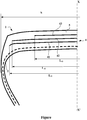
- the figure is not shown to scale for ease of understanding.
- the figure only shows a half-view of a tire which is extended symmetrically with respect to the axis XX 'which represents the circumferential median plane, or equatorial plane, of a tire.
- the crown frame is itself capped with a tread 6.
- the maximum axial width W of the tire is equal to 317 mm.
- the axial width L 41 of the first working layer 41 is equal to 252 mm.
- the axial width L 42 of the second working layer 42 is equal to 232 mm.
- the last crown ply 43 has a width L 43 equal to 124 mm.
- the modulus of elasticity under tension at 10% elongation of the calendering layers of the protective layer 43 is less than 8.5 MPa and the Z score of macro dispersion greater than 85.
- Log (p) which expresses the electrical resistivity of the calendering layers of the protective layer 43 is greater than 8 Ohm.cm.
- tan ( ⁇ ) max The maximum value of tan ( ⁇ ), denoted tan ( ⁇ ) max, of the calendering layers of the protective layer 43 is less than 0.070.
- Tests were carried out with various tires produced according to the invention and compared with reference tires.
- Tests are carried out by varying the characteristics of the calendering mixtures of the protective layer 43, in particular their modulus of elasticity under tension at 10% elongation and the score Z.
- the tires I according to the invention with a protective layer consist of mixtures chosen from mixtures 1 to 3.
- Reference tires T are produced with a protective layer the calenders of which consist of the mixture R1 or the mixture R2.
- the Log (p) expresses the volume electrical resistivity of the calendering layers of the protective layer 43, p being expressed in ohm.cm.
- Tests corresponding to endurance tests were carried out by rolling with vehicles traveling on a rolling surface made up of aggressive stones which get stuck in the hollow areas of the tire tread pattern. The vehicles then pass through a saline solution tank to allow the corrosive liquid to propagate within the tire via the cracks formed due to the attacks caused by the stones.
- the reinforcing elements of the protective layer are analyzed.
- the measurements taken correspond to the lengths of corroded reinforcing elements and the number of breaks of said reinforcing elements.
Landscapes
- Engineering & Computer Science (AREA)
- Mechanical Engineering (AREA)
- Compositions Of Macromolecular Compounds (AREA)
- Tires In General (AREA)
Claims (13)
- Reifen mit radialer Karkassenarmierung umfassend eine Scheitelarmierung, die von mindestens zwei Arbeitsscheitelschichten aus Verstärkungselementen, die einen Winkel mit der Umfangsrichtung bilden, gebildet ist, und von mindestens einer Schutzschicht aus metallischen Verstärkungselementen, die zwischen zwei Kalandrierschichten aus einer Elastomermischung aufweisend einen verstärkenden Füllstoff, der zumindest von Ruß gebildet ist, eingefügt ist, wobei die Schutzschicht radial außerhalb der mindestens zwei Arbeitsscheitelschichten gelegen ist, wobei die Scheitelarmierung radial von einem Laufstreifen bedeckt ist, wobei der Laufstreifen über zwei Flanken mit zwei Wülsten verbunden ist, dadurch gekennzeichnet, dass der Elastizitätsmodul unter Spannung bei 10 % Dehnung zumindest der radial am weitesten außen gelegenen Kalandrierschicht mindestens einer Schutzschicht, gemessen nach der Norm AFNOR-NFT-46002 vom September 1988, kleiner als 8,5 MPa ist und dadurch, dass zumindest die radial am weitesten außen gelegene Kalandrierschicht mindestens einer Schutzschicht einen Z-Wert der Makrodispersion aufweist, der gemäß der Norm ISO 11345 gemessen wird, der über 85 liegt.
- Reifen nach Anspruch 1, dadurch gekennzeichnet, dass zumindest die radial am weitesten außen gelegene Kalandrierschicht mindestens einer Schutzschicht eine Elastomermischung auf Basis von Naturkautschuk oder synthetischem Polyisopren mit einer Mehrheit von cis-1,4-Ketten und eventuell mindestens einem anderen Dienelastomer ist, wobei der Naturkautschuk oder das synthetische Polyisopren im Falle eines Verschnitts in einem Mehrheitsanteil im Verhältnis zum Anteil des anderen oder der anderen genutzten Dienelastomere vorhanden ist, und von einem verstärkenden Füllstoff, der von Folgendem gebildet ist:a) entweder von Ruß, der zu einem Anteil zwischen 20 und 80 pce eingesetzt wird,b) oder von einem Verschnitt aus Ruß und einem weißen Füllstoff, wobei der Gesamt-Füllstoffanteil zwischen 20 und 80 pce und vorzugsweise zwischen 40 und 60 pce liegt, wobei der weiße Füllstoff vom Typ Kieselsäure und/oder Tonerde ist, aufweisend SiOH- und/oder AlOH-Oberflächenfunktionen, der aus der Gruppe gewählt ist, die von gefällten oder pyrogenen Kieselsäuren, Tonerden oder Aluminosilicaten oder auch Rußen gebildet ist, die bei oder nach der Synthese modifiziert wurden, mit einer spezifischen BET-Oberfläche, die gemäß der Norm NFT 45007 vom November 1987 gemessen wird, die zwischen 30 und 260 m2/g liegt.
- Reifen nach einem der Ansprüche 1 oder 2, dadurch gekennzeichnet, dass zumindest die radial am weitesten außen gelegene Kalandrierschicht mindestens einer Schutzschicht einen spezifischen elektrischen Volumenwiderstand p aufweist, so dass log(p) größer als 8 ist.
- Reifen nach einem der Ansprüche 1 bis 3, dadurch gekennzeichnet, dass die metallischen Verstärkungselemente zumindest der Schutzschicht Seile sind, die bei der Durchlässigkeitsprüfung einen Durchsatz unter 5 cm3/mn aufweisen.
- Reifen nach einem der Ansprüche 1 bis 4, dadurch gekennzeichnet, dass die Verstärkungselemente der Schutzschicht bezogen auf die Umfangsrichtung mit einem Winkel derselben Richtung wie der Winkel, der von den Verstärkungselementen der Arbeitsscheitelschicht gebildet ist, die ihr radial benachbart ist, ausgerichtet sind.
- Reifen nach einem der vorhergehenden Ansprüche, dadurch gekennzeichnet, dass der Maximalwert von tan(δ), der mit tan(δ)max angegeben ist, zumindest der radial am weitesten außen gelegenen Kalandrierschicht mindestens einer Schutzschicht kleiner als 0,080 ist.
- Reifen nach einem der vorhergehenden Ansprüche, dadurch gekennzeichnet, dass die Scheitelarmierung mindestens eine Schicht aus Umfangsverstärkungselementen aufweist.
- Reifen nach Anspruch 7, dadurch gekennzeichnet, dass die Schicht aus Umfangsverstärkungselementen radial zwischen zwei Arbeitsscheitelschichten angeordnet ist.
- Reifen nach einem der Ansprüche 7 oder 8, wobei die mindestens zwei Arbeitsscheitelschichten von Verstärkungselementen gebildet sind, die zwischen zwei Kalandrierschichten aus Gummimasse eingefügt sind, dadurch gekennzeichnet, dass der Elastizitätsmodul unter Spannung bei 10 % Dehnung mindestens einer Kalandrierschicht mindestens einer Arbeitsscheitelschicht kleiner als 8,5 MPa ist, dadurch, dass der Maximalwert tan(δ), der mit tan(δ)max angegeben ist, der mindestens einen Kalandrierschicht mindestens einer Arbeitsscheitelschicht kleiner als 0,100 ist.
- Reifen nach Anspruch 9, dadurch gekennzeichnet, dass die mindestens eine Kalandrierschicht mindestens einer Arbeitsscheitelschicht eine Elastomermischung auf Basis von Naturkautschuk oder synthetischem Polyisopren mit einer Mehrheit von cis-1,4-Ketten und eventuell mindestens einem anderen Dienelastomer ist, wobei der Naturkautschuk oder das synthetische Polyisopren im Falle eines Verschnitts in einem Mehrheitsanteil im Verhältnis zum Anteil des anderen oder der anderen genutzten Dienelastomere vorhanden ist, und von einem verstärkenden Füllstoff, der von Folgendem gebildet ist:a) entweder von Ruß mit einer spezifischen BET-Oberfläche größer als 60 m2/g,i. der zu einem Anteil zwischen 20 und 40 pce eingesetzt wird, wenn der Strukturindex des Rußes (COAN) größer als 85 ist,ii. der zu einem Anteil zwischen 20 und 60 pce eingesetzt wird, wenn der Strukturindex des Rußes (COAN) kleiner als 85 ist,b) oder von Ruß mit einer spezifischen BET-Oberfläche kleiner als 60 m2/g unabhängig von dessen Strukturindex, der zu einem Anteil zwischen 20 und 80 pce und vorzugsweise zwischen 30 und 50 pce eingesetzt wird,c) oder von einem weißen Füllstoff vom Typ Kieselsäure und/oder Tonerde, aufweisend SiOH- und/oder AlOH-Oberflächenfunktionen, der aus der Gruppe gewählt ist, die von gefällten oder pyrogenen Kieselsäuren, Tonerden oder Aluminosilicaten oder auch Rußen gebildet ist, die bei oder nach der Synthese modifiziert wurden, mit einer spezifischen BET-Oberfläche zwischen 130 et 260 m2/g und vorzugsweise größer als 150 m2/g, der zu einem Anteil zwischen 20 und 80 pce und vorzugsweise zwischen 30 und 50 pce eingesetzt wird,d) oder von einem Verschnitt aus Ruß, der in (a) beschrieben ist, und/oder Ruß, der in (b) beschrieben ist, und/oder einem weißen Füllstoff, der in (c) beschrieben ist, wobei der Gesamt-Füllstoffanteil zwischen 20 und 80 pce und vorzugsweise zwischen 40 und 60 pce liegt.
- Reifen nach einem der vorhergehenden Ansprüche, dadurch gekennzeichnet, dass die mindestens zwei Scheitel-Arbeitsschichten von Verstärkungselementen gebildet ist, vorzugsweise nicht dehnbaren, die durch Bilden von Winkeln zwischen 10° und 45° mit der Umfangsrichtung von einer Schicht zur anderen gekreuzt sind.
- Reifen nach einem der vorhergehenden Ansprüche, dadurch gekennzeichnet, dass die Verstärkungselemente mindestens einer Schicht aus Umfangsverstärkungselementen metallische Verstärkungselemente sind, die einen Sekantenmodul bei 0,7 % Dehnung zwischen 10 und 120 GPa und einen maximalen Tangentenmodul kleiner als 150 GPa aufweisen.
- Reifen nach einem der vorhergehenden Ansprüche, dadurch gekennzeichnet, dass die Scheitelarmierung ferner eine Triangulationsschicht aufweist, die von metallischen Verstärkungselementen gebildet ist, die mit der Umfangsrichtung Winkel größer als 45° bilden.
Applications Claiming Priority (2)
| Application Number | Priority Date | Filing Date | Title |
|---|---|---|---|
| FR1654495A FR3051399B1 (fr) | 2016-05-20 | 2016-05-20 | Pneumatique presentant une couche de protection avec des proprietes d’endurance ameliorees |
| PCT/FR2017/051200 WO2017198953A1 (fr) | 2016-05-20 | 2017-05-18 | Pneumatique presentant une couche de protection avec des proprietes d'endurance ameliorees |
Publications (2)
| Publication Number | Publication Date |
|---|---|
| EP3458285A1 EP3458285A1 (de) | 2019-03-27 |
| EP3458285B1 true EP3458285B1 (de) | 2020-11-11 |
Family
ID=56404173
Family Applications (1)
| Application Number | Title | Priority Date | Filing Date |
|---|---|---|---|
| EP17730856.6A Active EP3458285B1 (de) | 2016-05-20 | 2017-05-18 | Reifen mit einer schutzschicht mit verbesserten dauerfestigkeitseigenschaften |
Country Status (3)
| Country | Link |
|---|---|
| EP (1) | EP3458285B1 (de) |
| FR (1) | FR3051399B1 (de) |
| WO (1) | WO2017198953A1 (de) |
Family Cites Families (9)
| Publication number | Priority date | Publication date | Assignee | Title |
|---|---|---|---|---|
| US6323273B1 (en) | 1995-05-22 | 2001-11-27 | Cabot Corporation | Elastomeric compounds incorporating silicon-treated carbon blacks |
| US5883179A (en) | 1995-10-25 | 1999-03-16 | The Yokohama Rubber Co., Ltd. | Rubber composition comprising carbon black surface treated with silica |
| WO1997036724A2 (en) | 1996-04-01 | 1997-10-09 | Cabot Corporation | Novel elastomer composites, method and apparatus |
| EP0931113A1 (de) | 1996-09-25 | 1999-07-28 | Cabot Corporation | Mit kieselsäurebeschichtete russe |
| FR2770458B1 (fr) | 1997-11-05 | 1999-12-03 | Michelin & Cie | Armature de sommet pour pneumatique "poids-lours" |
| WO2004076204A1 (fr) | 2003-02-17 | 2004-09-10 | Societe De Technologie Michelin | Armature de sommet pour pneumatique radial |
| FR3022839B1 (fr) * | 2014-06-26 | 2017-11-24 | Michelin & Cie | Pneumatique comportant une couche d'elements de renforcement circonferentiels |
| FR3022843B1 (fr) * | 2014-06-26 | 2017-11-24 | Michelin & Cie | Pneumatique comportant une couche d'elements de renforcement circonferentiels |
| FR3022841B1 (fr) * | 2014-06-26 | 2016-06-10 | Michelin & Cie | Pneumatique comportant une couche d'elements de renforcement circonferentiels |
-
2016
- 2016-05-20 FR FR1654495A patent/FR3051399B1/fr not_active Expired - Fee Related
-
2017
- 2017-05-18 WO PCT/FR2017/051200 patent/WO2017198953A1/fr unknown
- 2017-05-18 EP EP17730856.6A patent/EP3458285B1/de active Active
Non-Patent Citations (1)
| Title |
|---|
| None * |
Also Published As
| Publication number | Publication date |
|---|---|
| WO2017198953A1 (fr) | 2017-11-23 |
| FR3051399B1 (fr) | 2018-05-11 |
| FR3051399A1 (fr) | 2017-11-24 |
| EP3458285A1 (de) | 2019-03-27 |
Similar Documents
| Publication | Publication Date | Title |
|---|---|---|
| EP3707010B1 (de) | Luftreifen mit leichtgewichtiger gürtelverstärkung | |
| EP3160763B1 (de) | Reifen mit einer schicht aus umlaufenden verstärkungselementen | |
| EP3458284B1 (de) | Reifen mit einer schutzschicht mit verbesserten dauerfestigkeitseigenschaften | |
| EP3160762B1 (de) | Reifen mit einer schicht aus umlaufenden verstärkungselementen | |
| EP3548308B1 (de) | Reifen mit einer leichten gürtelverstärkung | |
| EP3710283B1 (de) | Reifen mit einer karkassenverstärkungsschicht mit verbesserten dauerfestigkeitseigenschaften | |
| EP3160770B1 (de) | Reifen mit einer schicht aus umlaufenden verstärkungselementen | |
| EP3390089B1 (de) | Reifen mit verbesserten eigenschaften der abnutzung und des rollwiderstands | |
| EP3390099B1 (de) | Reifen mit verbesserten eigenschaften der abriebfestigkeit und des rollwiderstands | |
| EP3160769B1 (de) | Reifen mit verbesserten dynamischen eigenschaften | |
| EP3458283B1 (de) | Reifen mit einer schutzschicht mit verbesserten dauerfestigkeitseigenschaften | |
| EP3458285B1 (de) | Reifen mit einer schutzschicht mit verbesserten dauerfestigkeitseigenschaften | |
| EP3390081B1 (de) | Reifen mit verbesserten abnutzungs- und rollwiderstandseigenschaften | |
| EP3390082B1 (de) | Reifen mit verbesserten abnutzungseigenschaften und verbessertem rollwiderstand | |
| EP3390080B1 (de) | Reifen mit verbesserten abnutzungs- und rollwiderstandseigenschaften | |
| EP3390086B1 (de) | Reifen mit verbesserten abnutzungs- und rollwiderstandseigenschaften | |
| EP3548307B1 (de) | Reifen mit einer leichten gürtelverstärkung | |
| EP3390084B1 (de) | Reifen mit verbesserten abnutzungs- und rollwiderstandseigenschaften | |
| EP3710284B1 (de) | Reifen mit einer karkassenverstärkungsschicht mit verbesserten dauerfestigkeitseigenschaften | |
| EP3390083B1 (de) | Reifen mit verbesserten abnutzungs- und rollwiderstandseigenschaften | |
| EP3390088B1 (de) | Reifen mit verbesserten abnutzungs- und rollwiderstandseigenschaften | |
| EP3390087B1 (de) | Reifen mit verbesserten eigenschaften der abnutzung und des rollwiderstands | |
| EP3390085B1 (de) | Reifen mit verbesserten abnutzungs- und rollwiderstandseigenschaften | |
| EP3390095B1 (de) | Reifen mit verbesserten abnutzungs- und rollwiderstandseigenschaften |
Legal Events
| Date | Code | Title | Description |
|---|---|---|---|
| STAA | Information on the status of an ep patent application or granted ep patent |
Free format text: STATUS: UNKNOWN |
|
| STAA | Information on the status of an ep patent application or granted ep patent |
Free format text: STATUS: THE INTERNATIONAL PUBLICATION HAS BEEN MADE |
|
| PUAI | Public reference made under article 153(3) epc to a published international application that has entered the european phase |
Free format text: ORIGINAL CODE: 0009012 |
|
| STAA | Information on the status of an ep patent application or granted ep patent |
Free format text: STATUS: REQUEST FOR EXAMINATION WAS MADE |
|
| 17P | Request for examination filed |
Effective date: 20181220 |
|
| AK | Designated contracting states |
Kind code of ref document: A1 Designated state(s): AL AT BE BG CH CY CZ DE DK EE ES FI FR GB GR HR HU IE IS IT LI LT LU LV MC MK MT NL NO PL PT RO RS SE SI SK SM TR |
|
| AX | Request for extension of the european patent |
Extension state: BA ME |
|
| DAV | Request for validation of the european patent (deleted) | ||
| DAX | Request for extension of the european patent (deleted) | ||
| STAA | Information on the status of an ep patent application or granted ep patent |
Free format text: STATUS: EXAMINATION IS IN PROGRESS |
|
| 17Q | First examination report despatched |
Effective date: 20200113 |
|
| GRAP | Despatch of communication of intention to grant a patent |
Free format text: ORIGINAL CODE: EPIDOSNIGR1 |
|
| STAA | Information on the status of an ep patent application or granted ep patent |
Free format text: STATUS: GRANT OF PATENT IS INTENDED |
|
| INTG | Intention to grant announced |
Effective date: 20200615 |
|
| GRAS | Grant fee paid |
Free format text: ORIGINAL CODE: EPIDOSNIGR3 |
|
| GRAA | (expected) grant |
Free format text: ORIGINAL CODE: 0009210 |
|
| STAA | Information on the status of an ep patent application or granted ep patent |
Free format text: STATUS: THE PATENT HAS BEEN GRANTED |
|
| AK | Designated contracting states |
Kind code of ref document: B1 Designated state(s): AL AT BE BG CH CY CZ DE DK EE ES FI FR GB GR HR HU IE IS IT LI LT LU LV MC MK MT NL NO PL PT RO RS SE SI SK SM TR |
|
| REG | Reference to a national code |
Ref country code: GB Ref legal event code: FG4D Free format text: NOT ENGLISH |
|
| REG | Reference to a national code |
Ref country code: CH Ref legal event code: EP |
|
| REG | Reference to a national code |
Ref country code: AT Ref legal event code: REF Ref document number: 1333096 Country of ref document: AT Kind code of ref document: T Effective date: 20201115 |
|
| REG | Reference to a national code |
Ref country code: DE Ref legal event code: R096 Ref document number: 602017027363 Country of ref document: DE |
|
| REG | Reference to a national code |
Ref country code: IE Ref legal event code: FG4D Free format text: LANGUAGE OF EP DOCUMENT: FRENCH |
|
| REG | Reference to a national code |
Ref country code: NL Ref legal event code: MP Effective date: 20201111 |
|
| REG | Reference to a national code |
Ref country code: AT Ref legal event code: MK05 Ref document number: 1333096 Country of ref document: AT Kind code of ref document: T Effective date: 20201111 |
|
| PG25 | Lapsed in a contracting state [announced via postgrant information from national office to epo] |
Ref country code: PT Free format text: LAPSE BECAUSE OF FAILURE TO SUBMIT A TRANSLATION OF THE DESCRIPTION OR TO PAY THE FEE WITHIN THE PRESCRIBED TIME-LIMIT Effective date: 20210311 Ref country code: RS Free format text: LAPSE BECAUSE OF FAILURE TO SUBMIT A TRANSLATION OF THE DESCRIPTION OR TO PAY THE FEE WITHIN THE PRESCRIBED TIME-LIMIT Effective date: 20201111 Ref country code: NO Free format text: LAPSE BECAUSE OF FAILURE TO SUBMIT A TRANSLATION OF THE DESCRIPTION OR TO PAY THE FEE WITHIN THE PRESCRIBED TIME-LIMIT Effective date: 20210211 Ref country code: FI Free format text: LAPSE BECAUSE OF FAILURE TO SUBMIT A TRANSLATION OF THE DESCRIPTION OR TO PAY THE FEE WITHIN THE PRESCRIBED TIME-LIMIT Effective date: 20201111 Ref country code: GR Free format text: LAPSE BECAUSE OF FAILURE TO SUBMIT A TRANSLATION OF THE DESCRIPTION OR TO PAY THE FEE WITHIN THE PRESCRIBED TIME-LIMIT Effective date: 20210212 |
|
| PG25 | Lapsed in a contracting state [announced via postgrant information from national office to epo] |
Ref country code: AT Free format text: LAPSE BECAUSE OF FAILURE TO SUBMIT A TRANSLATION OF THE DESCRIPTION OR TO PAY THE FEE WITHIN THE PRESCRIBED TIME-LIMIT Effective date: 20201111 Ref country code: SE Free format text: LAPSE BECAUSE OF FAILURE TO SUBMIT A TRANSLATION OF THE DESCRIPTION OR TO PAY THE FEE WITHIN THE PRESCRIBED TIME-LIMIT Effective date: 20201111 Ref country code: IS Free format text: LAPSE BECAUSE OF FAILURE TO SUBMIT A TRANSLATION OF THE DESCRIPTION OR TO PAY THE FEE WITHIN THE PRESCRIBED TIME-LIMIT Effective date: 20210311 Ref country code: LV Free format text: LAPSE BECAUSE OF FAILURE TO SUBMIT A TRANSLATION OF THE DESCRIPTION OR TO PAY THE FEE WITHIN THE PRESCRIBED TIME-LIMIT Effective date: 20201111 Ref country code: PL Free format text: LAPSE BECAUSE OF FAILURE TO SUBMIT A TRANSLATION OF THE DESCRIPTION OR TO PAY THE FEE WITHIN THE PRESCRIBED TIME-LIMIT Effective date: 20201111 Ref country code: BG Free format text: LAPSE BECAUSE OF FAILURE TO SUBMIT A TRANSLATION OF THE DESCRIPTION OR TO PAY THE FEE WITHIN THE PRESCRIBED TIME-LIMIT Effective date: 20210211 |
|
| REG | Reference to a national code |
Ref country code: LT Ref legal event code: MG9D |
|
| PG25 | Lapsed in a contracting state [announced via postgrant information from national office to epo] |
Ref country code: HR Free format text: LAPSE BECAUSE OF FAILURE TO SUBMIT A TRANSLATION OF THE DESCRIPTION OR TO PAY THE FEE WITHIN THE PRESCRIBED TIME-LIMIT Effective date: 20201111 |
|
| PG25 | Lapsed in a contracting state [announced via postgrant information from national office to epo] |
Ref country code: RO Free format text: LAPSE BECAUSE OF FAILURE TO SUBMIT A TRANSLATION OF THE DESCRIPTION OR TO PAY THE FEE WITHIN THE PRESCRIBED TIME-LIMIT Effective date: 20201111 Ref country code: SK Free format text: LAPSE BECAUSE OF FAILURE TO SUBMIT A TRANSLATION OF THE DESCRIPTION OR TO PAY THE FEE WITHIN THE PRESCRIBED TIME-LIMIT Effective date: 20201111 Ref country code: LT Free format text: LAPSE BECAUSE OF FAILURE TO SUBMIT A TRANSLATION OF THE DESCRIPTION OR TO PAY THE FEE WITHIN THE PRESCRIBED TIME-LIMIT Effective date: 20201111 Ref country code: CZ Free format text: LAPSE BECAUSE OF FAILURE TO SUBMIT A TRANSLATION OF THE DESCRIPTION OR TO PAY THE FEE WITHIN THE PRESCRIBED TIME-LIMIT Effective date: 20201111 Ref country code: EE Free format text: LAPSE BECAUSE OF FAILURE TO SUBMIT A TRANSLATION OF THE DESCRIPTION OR TO PAY THE FEE WITHIN THE PRESCRIBED TIME-LIMIT Effective date: 20201111 Ref country code: SM Free format text: LAPSE BECAUSE OF FAILURE TO SUBMIT A TRANSLATION OF THE DESCRIPTION OR TO PAY THE FEE WITHIN THE PRESCRIBED TIME-LIMIT Effective date: 20201111 |
|
| REG | Reference to a national code |
Ref country code: DE Ref legal event code: R097 Ref document number: 602017027363 Country of ref document: DE |
|
| PG25 | Lapsed in a contracting state [announced via postgrant information from national office to epo] |
Ref country code: DK Free format text: LAPSE BECAUSE OF FAILURE TO SUBMIT A TRANSLATION OF THE DESCRIPTION OR TO PAY THE FEE WITHIN THE PRESCRIBED TIME-LIMIT Effective date: 20201111 |
|
| PLBE | No opposition filed within time limit |
Free format text: ORIGINAL CODE: 0009261 |
|
| STAA | Information on the status of an ep patent application or granted ep patent |
Free format text: STATUS: NO OPPOSITION FILED WITHIN TIME LIMIT |
|
| 26N | No opposition filed |
Effective date: 20210812 |
|
| PG25 | Lapsed in a contracting state [announced via postgrant information from national office to epo] |
Ref country code: IT Free format text: LAPSE BECAUSE OF FAILURE TO SUBMIT A TRANSLATION OF THE DESCRIPTION OR TO PAY THE FEE WITHIN THE PRESCRIBED TIME-LIMIT Effective date: 20201111 Ref country code: NL Free format text: LAPSE BECAUSE OF FAILURE TO SUBMIT A TRANSLATION OF THE DESCRIPTION OR TO PAY THE FEE WITHIN THE PRESCRIBED TIME-LIMIT Effective date: 20201111 Ref country code: AL Free format text: LAPSE BECAUSE OF FAILURE TO SUBMIT A TRANSLATION OF THE DESCRIPTION OR TO PAY THE FEE WITHIN THE PRESCRIBED TIME-LIMIT Effective date: 20201111 |
|
| PG25 | Lapsed in a contracting state [announced via postgrant information from national office to epo] |
Ref country code: SI Free format text: LAPSE BECAUSE OF FAILURE TO SUBMIT A TRANSLATION OF THE DESCRIPTION OR TO PAY THE FEE WITHIN THE PRESCRIBED TIME-LIMIT Effective date: 20201111 |
|
| REG | Reference to a national code |
Ref country code: CH Ref legal event code: PL |
|
| GBPC | Gb: european patent ceased through non-payment of renewal fee |
Effective date: 20210518 |
|
| PG25 | Lapsed in a contracting state [announced via postgrant information from national office to epo] |
Ref country code: ES Free format text: LAPSE BECAUSE OF FAILURE TO SUBMIT A TRANSLATION OF THE DESCRIPTION OR TO PAY THE FEE WITHIN THE PRESCRIBED TIME-LIMIT Effective date: 20201111 Ref country code: CH Free format text: LAPSE BECAUSE OF NON-PAYMENT OF DUE FEES Effective date: 20210531 Ref country code: LI Free format text: LAPSE BECAUSE OF NON-PAYMENT OF DUE FEES Effective date: 20210531 Ref country code: MC Free format text: LAPSE BECAUSE OF FAILURE TO SUBMIT A TRANSLATION OF THE DESCRIPTION OR TO PAY THE FEE WITHIN THE PRESCRIBED TIME-LIMIT Effective date: 20201111 Ref country code: LU Free format text: LAPSE BECAUSE OF NON-PAYMENT OF DUE FEES Effective date: 20210518 |
|
| REG | Reference to a national code |
Ref country code: BE Ref legal event code: MM Effective date: 20210531 |
|
| PG25 | Lapsed in a contracting state [announced via postgrant information from national office to epo] |
Ref country code: IE Free format text: LAPSE BECAUSE OF NON-PAYMENT OF DUE FEES Effective date: 20210518 Ref country code: GB Free format text: LAPSE BECAUSE OF NON-PAYMENT OF DUE FEES Effective date: 20210518 |
|
| PG25 | Lapsed in a contracting state [announced via postgrant information from national office to epo] |
Ref country code: IS Free format text: LAPSE BECAUSE OF FAILURE TO SUBMIT A TRANSLATION OF THE DESCRIPTION OR TO PAY THE FEE WITHIN THE PRESCRIBED TIME-LIMIT Effective date: 20210311 |
|
| PG25 | Lapsed in a contracting state [announced via postgrant information from national office to epo] |
Ref country code: BE Free format text: LAPSE BECAUSE OF NON-PAYMENT OF DUE FEES Effective date: 20210531 |
|
| PG25 | Lapsed in a contracting state [announced via postgrant information from national office to epo] |
Ref country code: CY Free format text: LAPSE BECAUSE OF FAILURE TO SUBMIT A TRANSLATION OF THE DESCRIPTION OR TO PAY THE FEE WITHIN THE PRESCRIBED TIME-LIMIT Effective date: 20201111 |
|
| PG25 | Lapsed in a contracting state [announced via postgrant information from national office to epo] |
Ref country code: HU Free format text: LAPSE BECAUSE OF FAILURE TO SUBMIT A TRANSLATION OF THE DESCRIPTION OR TO PAY THE FEE WITHIN THE PRESCRIBED TIME-LIMIT; INVALID AB INITIO Effective date: 20170518 |
|
| PGFP | Annual fee paid to national office [announced via postgrant information from national office to epo] |
Ref country code: FR Payment date: 20230526 Year of fee payment: 7 Ref country code: DE Payment date: 20230519 Year of fee payment: 7 |
|
| PG25 | Lapsed in a contracting state [announced via postgrant information from national office to epo] |
Ref country code: MK Free format text: LAPSE BECAUSE OF FAILURE TO SUBMIT A TRANSLATION OF THE DESCRIPTION OR TO PAY THE FEE WITHIN THE PRESCRIBED TIME-LIMIT Effective date: 20201111 |