EP3458186B1 - Diamond tool piece - Google Patents
Diamond tool piece Download PDFInfo
- Publication number
- EP3458186B1 EP3458186B1 EP17725553.6A EP17725553A EP3458186B1 EP 3458186 B1 EP3458186 B1 EP 3458186B1 EP 17725553 A EP17725553 A EP 17725553A EP 3458186 B1 EP3458186 B1 EP 3458186B1
- Authority
- EP
- European Patent Office
- Prior art keywords
- diamond
- nitrogen
- hpht
- tool piece
- diamond tool
- Prior art date
- Legal status (The legal status is an assumption and is not a legal conclusion. Google has not performed a legal analysis and makes no representation as to the accuracy of the status listed.)
- Active
Links
Images

Classifications
-
- B—PERFORMING OPERATIONS; TRANSPORTING
- B23—MACHINE TOOLS; METAL-WORKING NOT OTHERWISE PROVIDED FOR
- B23B—TURNING; BORING
- B23B27/00—Tools for turning or boring machines; Tools of a similar kind in general; Accessories therefor
- B23B27/14—Cutting tools of which the bits or tips or cutting inserts are of special material
- B23B27/148—Composition of the cutting inserts
-
- C—CHEMISTRY; METALLURGY
- C30—CRYSTAL GROWTH
- C30B—SINGLE-CRYSTAL GROWTH; UNIDIRECTIONAL SOLIDIFICATION OF EUTECTIC MATERIAL OR UNIDIRECTIONAL DEMIXING OF EUTECTOID MATERIAL; REFINING BY ZONE-MELTING OF MATERIAL; PRODUCTION OF A HOMOGENEOUS POLYCRYSTALLINE MATERIAL WITH DEFINED STRUCTURE; SINGLE CRYSTALS OR HOMOGENEOUS POLYCRYSTALLINE MATERIAL WITH DEFINED STRUCTURE; AFTER-TREATMENT OF SINGLE CRYSTALS OR A HOMOGENEOUS POLYCRYSTALLINE MATERIAL WITH DEFINED STRUCTURE; APPARATUS THEREFOR
- C30B29/00—Single crystals or homogeneous polycrystalline material with defined structure characterised by the material or by their shape
- C30B29/02—Elements
- C30B29/04—Diamond
-
- B—PERFORMING OPERATIONS; TRANSPORTING
- B01—PHYSICAL OR CHEMICAL PROCESSES OR APPARATUS IN GENERAL
- B01J—CHEMICAL OR PHYSICAL PROCESSES, e.g. CATALYSIS OR COLLOID CHEMISTRY; THEIR RELEVANT APPARATUS
- B01J3/00—Processes of utilising sub-atmospheric or super-atmospheric pressure to effect chemical or physical change of matter; Apparatus therefor
- B01J3/06—Processes using ultra-high pressure, e.g. for the formation of diamonds; Apparatus therefor, e.g. moulds or dies
- B01J3/065—Presses for the formation of diamonds or boronitrides
-
- C—CHEMISTRY; METALLURGY
- C01—INORGANIC CHEMISTRY
- C01B—NON-METALLIC ELEMENTS; COMPOUNDS THEREOF; METALLOIDS OR COMPOUNDS THEREOF NOT COVERED BY SUBCLASS C01C
- C01B32/00—Carbon; Compounds thereof
- C01B32/25—Diamond
-
- C—CHEMISTRY; METALLURGY
- C01—INORGANIC CHEMISTRY
- C01B—NON-METALLIC ELEMENTS; COMPOUNDS THEREOF; METALLOIDS OR COMPOUNDS THEREOF NOT COVERED BY SUBCLASS C01C
- C01B32/00—Carbon; Compounds thereof
- C01B32/25—Diamond
- C01B32/28—After-treatment, e.g. purification, irradiation, separation or recovery
-
- C—CHEMISTRY; METALLURGY
- C04—CEMENTS; CONCRETE; ARTIFICIAL STONE; CERAMICS; REFRACTORIES
- C04B—LIME, MAGNESIA; SLAG; CEMENTS; COMPOSITIONS THEREOF, e.g. MORTARS, CONCRETE OR LIKE BUILDING MATERIALS; ARTIFICIAL STONE; CERAMICS; REFRACTORIES; TREATMENT OF NATURAL STONE
- C04B35/00—Shaped ceramic products characterised by their composition; Ceramics compositions; Processing powders of inorganic compounds preparatory to the manufacturing of ceramic products
- C04B35/515—Shaped ceramic products characterised by their composition; Ceramics compositions; Processing powders of inorganic compounds preparatory to the manufacturing of ceramic products based on non-oxide ceramics
- C04B35/52—Shaped ceramic products characterised by their composition; Ceramics compositions; Processing powders of inorganic compounds preparatory to the manufacturing of ceramic products based on non-oxide ceramics based on carbon, e.g. graphite
-
- C—CHEMISTRY; METALLURGY
- C30—CRYSTAL GROWTH
- C30B—SINGLE-CRYSTAL GROWTH; UNIDIRECTIONAL SOLIDIFICATION OF EUTECTIC MATERIAL OR UNIDIRECTIONAL DEMIXING OF EUTECTOID MATERIAL; REFINING BY ZONE-MELTING OF MATERIAL; PRODUCTION OF A HOMOGENEOUS POLYCRYSTALLINE MATERIAL WITH DEFINED STRUCTURE; SINGLE CRYSTALS OR HOMOGENEOUS POLYCRYSTALLINE MATERIAL WITH DEFINED STRUCTURE; AFTER-TREATMENT OF SINGLE CRYSTALS OR A HOMOGENEOUS POLYCRYSTALLINE MATERIAL WITH DEFINED STRUCTURE; APPARATUS THEREFOR
- C30B31/00—Diffusion or doping processes for single crystals or homogeneous polycrystalline material with defined structure; Apparatus therefor
- C30B31/20—Doping by irradiation with electromagnetic waves or by particle radiation
-
- C—CHEMISTRY; METALLURGY
- C30—CRYSTAL GROWTH
- C30B—SINGLE-CRYSTAL GROWTH; UNIDIRECTIONAL SOLIDIFICATION OF EUTECTIC MATERIAL OR UNIDIRECTIONAL DEMIXING OF EUTECTOID MATERIAL; REFINING BY ZONE-MELTING OF MATERIAL; PRODUCTION OF A HOMOGENEOUS POLYCRYSTALLINE MATERIAL WITH DEFINED STRUCTURE; SINGLE CRYSTALS OR HOMOGENEOUS POLYCRYSTALLINE MATERIAL WITH DEFINED STRUCTURE; AFTER-TREATMENT OF SINGLE CRYSTALS OR A HOMOGENEOUS POLYCRYSTALLINE MATERIAL WITH DEFINED STRUCTURE; APPARATUS THEREFOR
- C30B33/00—After-treatment of single crystals or homogeneous polycrystalline material with defined structure
- C30B33/02—Heat treatment
-
- C—CHEMISTRY; METALLURGY
- C30—CRYSTAL GROWTH
- C30B—SINGLE-CRYSTAL GROWTH; UNIDIRECTIONAL SOLIDIFICATION OF EUTECTIC MATERIAL OR UNIDIRECTIONAL DEMIXING OF EUTECTOID MATERIAL; REFINING BY ZONE-MELTING OF MATERIAL; PRODUCTION OF A HOMOGENEOUS POLYCRYSTALLINE MATERIAL WITH DEFINED STRUCTURE; SINGLE CRYSTALS OR HOMOGENEOUS POLYCRYSTALLINE MATERIAL WITH DEFINED STRUCTURE; AFTER-TREATMENT OF SINGLE CRYSTALS OR A HOMOGENEOUS POLYCRYSTALLINE MATERIAL WITH DEFINED STRUCTURE; APPARATUS THEREFOR
- C30B33/00—After-treatment of single crystals or homogeneous polycrystalline material with defined structure
- C30B33/04—After-treatment of single crystals or homogeneous polycrystalline material with defined structure using electric or magnetic fields or particle radiation
-
- B—PERFORMING OPERATIONS; TRANSPORTING
- B01—PHYSICAL OR CHEMICAL PROCESSES OR APPARATUS IN GENERAL
- B01J—CHEMICAL OR PHYSICAL PROCESSES, e.g. CATALYSIS OR COLLOID CHEMISTRY; THEIR RELEVANT APPARATUS
- B01J2203/00—Processes utilising sub- or super atmospheric pressure
- B01J2203/06—High pressure synthesis
- B01J2203/0605—Composition of the material to be processed
- B01J2203/062—Diamond
-
- B—PERFORMING OPERATIONS; TRANSPORTING
- B01—PHYSICAL OR CHEMICAL PROCESSES OR APPARATUS IN GENERAL
- B01J—CHEMICAL OR PHYSICAL PROCESSES, e.g. CATALYSIS OR COLLOID CHEMISTRY; THEIR RELEVANT APPARATUS
- B01J2203/00—Processes utilising sub- or super atmospheric pressure
- B01J2203/06—High pressure synthesis
- B01J2203/065—Composition of the material produced
- B01J2203/0655—Diamond
-
- B—PERFORMING OPERATIONS; TRANSPORTING
- B01—PHYSICAL OR CHEMICAL PROCESSES OR APPARATUS IN GENERAL
- B01J—CHEMICAL OR PHYSICAL PROCESSES, e.g. CATALYSIS OR COLLOID CHEMISTRY; THEIR RELEVANT APPARATUS
- B01J2203/00—Processes utilising sub- or super atmospheric pressure
- B01J2203/06—High pressure synthesis
- B01J2203/0675—Structural or physico-chemical features of the materials processed
- B01J2203/069—Recrystallisation
-
- B—PERFORMING OPERATIONS; TRANSPORTING
- B01—PHYSICAL OR CHEMICAL PROCESSES OR APPARATUS IN GENERAL
- B01J—CHEMICAL OR PHYSICAL PROCESSES, e.g. CATALYSIS OR COLLOID CHEMISTRY; THEIR RELEVANT APPARATUS
- B01J2203/00—Processes utilising sub- or super atmospheric pressure
- B01J2203/06—High pressure synthesis
- B01J2203/0675—Structural or physico-chemical features of the materials processed
- B01J2203/0695—Colour change
-
- B—PERFORMING OPERATIONS; TRANSPORTING
- B23—MACHINE TOOLS; METAL-WORKING NOT OTHERWISE PROVIDED FOR
- B23B—TURNING; BORING
- B23B2226/00—Materials of tools or workpieces not comprising a metal
- B23B2226/31—Diamond
-
- B—PERFORMING OPERATIONS; TRANSPORTING
- B23—MACHINE TOOLS; METAL-WORKING NOT OTHERWISE PROVIDED FOR
- B23B—TURNING; BORING
- B23B2226/00—Materials of tools or workpieces not comprising a metal
- B23B2226/31—Diamond
- B23B2226/315—Diamond polycrystalline [PCD]
-
- C—CHEMISTRY; METALLURGY
- C01—INORGANIC CHEMISTRY
- C01P—INDEXING SCHEME RELATING TO STRUCTURAL AND PHYSICAL ASPECTS OF SOLID INORGANIC COMPOUNDS
- C01P2002/00—Crystal-structural characteristics
- C01P2002/50—Solid solutions
- C01P2002/52—Solid solutions containing elements as dopants
- C01P2002/54—Solid solutions containing elements as dopants one element only
-
- C—CHEMISTRY; METALLURGY
- C04—CEMENTS; CONCRETE; ARTIFICIAL STONE; CERAMICS; REFRACTORIES
- C04B—LIME, MAGNESIA; SLAG; CEMENTS; COMPOSITIONS THEREOF, e.g. MORTARS, CONCRETE OR LIKE BUILDING MATERIALS; ARTIFICIAL STONE; CERAMICS; REFRACTORIES; TREATMENT OF NATURAL STONE
- C04B2235/00—Aspects relating to ceramic starting mixtures or sintered ceramic products
- C04B2235/02—Composition of constituents of the starting material or of secondary phases of the final product
- C04B2235/30—Constituents and secondary phases not being of a fibrous nature
- C04B2235/42—Non metallic elements added as constituents or additives, e.g. sulfur, phosphor, selenium or tellurium
- C04B2235/422—Carbon
- C04B2235/427—Diamond
Definitions
- the present invention relates to a synthetic high-pressure high-temperature, HPHT, diamond tool piece.
- a user For any application a user must consider a number of factors when choosing a tool material. Such factors including: cost; toughness; wear rate/hardness; ability to process a desired working surface such as a cutting edge; useful lifetime; and inertness to chemical effects with the material to be processed.
- An ideal tool material is one which is both hard and tough. These two properties of materials used in wear and tear applications are often presented on two perpendicular axes. Very simply, wear is a measurement of the amount of material removed per unit of operation. Toughness is a measure of a material's resistance to crack propagation.
- Diamond materials are the materials of choice for many premium performance cutting, drilling, grinding and polishing tools. Diamond materials are used in tooling solutions across a range of industries including a variety of metal, stone and woodworking industries. Examples include aerospace and automotive manufacturing, furniture production, stone quarrying, construction, mining and tunnelling, mineral processing, and the oil and gas industries.
- diamond The hardness properties of diamond make it a particularly suitable material in terms of wear resistance.
- diamond's limited ability to plastically deform under stress at the tool's working temperature leads to more rapid crack propagation in comparison to tougher materials such as steel.
- WO 01/79583 teaches a process for improving the durability of a diamond-type tool to increase the impact strength and fracture toughness.
- the process involves implanting ions into the surface of a diamond-type tool.
- Ion implantation is a materials engineering process by which ions of a material can be implanted into another solid, thereby changing the physical properties of the solid. Under typical circumstances ions are implanted to a depth in the range 10 nanometers to 1 micrometer.
- WO 01/79583 teaches ion implantation which penetrates a diamond surface to a depth in the range 0.02 ⁇ m to 0.2 ⁇ m.
- Preferred ions include chromium, nickel, ruthenium, tantalum, titanium and yttrium.
- US4184079 and GB1588445 also teach a method for toughening diamond by bombarding the diamond with ions of sufficient energy to penetrate the diamond surface.
- ions include carbon, nitrogen and hydrogen ions. It is described that the ions form a dislocation network in the diamond crystal lattice thereby inhibiting microcleavage of the diamond. It is further described that the dislocations can be confined to a depth of from 10 nm to 1 ⁇ m below the surface of the diamond crystals in order to a hard skin on the surface thereof.
- the dose of ions should be produce quite small, in the range 10 16 to 10 18 ions cm -2 , and have energies in the range 10 keV to 10 MeV, more preferably less than 100 keV so that the species implanted by the bombardment do not have a detrimental effect on the diamond material.
- ion bombardment of diamond results in the amorphisation and softening of the surface unless the temperature is held sufficiently high to maintain the crystal structure, it is taught to use a temperature of at least 500°C during ion bombardment.
- GB1588418 discloses a process for improving the wear characteristics of industrial diamonds.
- the process comprises implanting ions into the surface of the diamond. Carbon and nitrogen ions are suggested for this purpose.
- US4012300 discloses a method of altering the friability of abrasive particles, particularly diamond and cubic boron nitride particles, by subjecting the particles to irradiation. Proton, neutrons and gamma radiation are suggested with neutrons being preferred.
- EP 3170926 A1 discloses a single crystal CVD diamond containing nitrogen atoms, in which a ratio of the number of isolated substitutional nitrogen atoms to a total number of nitrogen atoms is in the range of 0.02% and 40%.
- WO 2011/151414 A2 discloses a method of irradiating diamond material with electrons to increase toughness and/or wear resistance. This is achieved by providing a plurality of isolated vacancy point defects having a concentration in the range of 1 ⁇ 10 4 to 1 ⁇ 10 22 vacancies/cm -3 .
- US 2007/0053823 A1 discloses a high-pressure high-temperature treatment of a natural diamond.
- EP 0346794 A1 discloses a method of making a diamond laser crystal by taking a synthetic type 1b diamond and subjecting it to a thermal treatment to convert type 1b nitrogen contained in the diamond to type 1aA nitrogen. This is then followed by irradiation and annealing steps.
- WO 2008/007336 A2 discloses a method of making diamond material with a nitrogen content of at least 100 ppm in combination with a transition metal vector.
- the resulting diamond material has characteristic crystal morphology index and crystal shape.
- a synthetic high-pressure high-temperature, HPHT, diamond tool piece wherein at least a portion of the HPHT diamond tool piece comprises an aggregated nitrogen centre to C-nitrogen centre ratio of greater than 30%, the portion being at least 40% of the volume of the HPHT diamond tool piece, the aggregated nitrogen centres comprising A centres and B centres, wherein the HPHT diamond tool piece is a single crystal HPHT diamond tool piece selected from one of: a wear part, a dresser, a wire drawing die, a gauge stone, a cutter and an engraving tool.
- the portion of the HPHT diamond tool piece comprises a nitrogen content selected from any of greater than 300 parts per million, greater than 350 parts per million and greater than 400 parts per million.
- the portion of the HPHT diamond tool piece comprises a nitrogen content selected from any of no greater than 800 parts per million; and no greater than 600 parts per million.
- the aggregated nitrogen centre to C-nitrogen centre ratio is optionally greater than 40%.
- the following description refers to substitutional nitrogen in the crystal lattice of diamond.
- This type of diamond is commonly termed type 1 diamond, and the nitrogen typically occupies positions in the crystal lattice in one of three main configurations. Nitrogen can form A centres, B centres of C centres. These types of nitrogen substitution are illustrated in Figure 1 , which shows a diamond crystal lattice in two dimensions for clarity. Carbon atoms are denoted by black circles and nitrogen atoms are denoted by white circles.
- An 'A' centre consists of a neutral nearest-neighbour pair of nitrogen atoms substituting for the carbon atoms.
- Diamond containing nitrogen predominantly in the A form is classed as Type laA.
- Figure 1 shows a lattice with two A centres.
- a 'B' centre is a carbon vacancy surrounded by four nitrogen atoms substituting for carbon atoms.
- Diamond containing nitrogen predominantly in the B form is classed as Type laB.
- a 'C' centre is a single substitutional nitrogen atom in the crystal lattice that has no ordered relationship to another substitutional nitrogen atom.
- Diamond containing nitrogen predominantly in the C form is classed as Type Ib.
- Type Ia diamonds can be colourless, brown, pink, and violet. Natural Type Ib diamonds can be deep yellow ("canary"), orange, brown or greenish. Type IIa and Type IIb diamond contain negligible nitrogen; some nitrogen is always present but in Type II diamond the levels are much lower than in Type I diamond. Type IIa and Type IIb diamond differ in that Type IIb diamond contains boron as an impurity. Type II diamonds vary from colourless to deep blue, pink or brown. The colour of a diamond is determined by the number, type and distribution of defects within the crystal structure. Colour can also be introduced if there is a fine dispersion of metallic particles in the diamond material. Crystal defects include dislocations, microcracks, twin boundaries, point defects, and low angle boundaries.
- the colour of diamond will depend on the type and distribution of impurities such as nitrogen and boron as well as the type and distribution of other defects such as dislocations.
- impurities such as nitrogen and boron
- other defects such as dislocations.
- nitrogen defect alone there are numerous different types of nitrogen defect alone, each having its own spectral characteristics.
- the term 'aggregated nitrogen centre' is used herein to denote all types of nitrogen centre other than C centres. These are predominantly A and B centres, but the skilled person will appreciate that there are other types of centre where a nitrogen atom is located in the crystal lattice adjacent to another nitrogen atom or a vacancy or a combination of any number of these.
- Figure 2 shows the basic steps involved in performing a method of making an embodiment of the present invention. The following numbering corresponds to that of Figure 2 :
- steps S2, S3 and S4 can be carried out in any suitable order, and may be repeated.
- the processing of step S4 could be carried out before the irradiation of S2 and the annealing of S3, or could be carried out between the irradiation step of S2 and the annealing step of S3.
- more than one irradiation step S2 or annealing step S3 may be used in order to apply different treatments such as radiation energy or dose, and for different amounts of time.
- the steps may be performed in any suitable order, but by way of example, Figure 3 shows an alternative order, with the following numbering corresponding to that of Figure 3 .
- Electron irradiation typically introduces vacancies in an isolated form. These may be in the neutral (V 0 ) and negative charge states (V - ).
- An iterative process can be used to find optimum defect levels.
- a diamond material can be irradiated, tested, re-irradiated, and so on to find the optimum defect levels for a particular diamond material for a particular type of tool piece and tool application.
- Electron irradiation is typically carried out with a beam source in the energy range 0.1 MeV to 12 MeV.
- the preferred energy is that which introduces a near uniform concentration of vacancies in a nitrogen doped diamond, while minimizing the formation of cascade damage e.g. vacancy chains. It has been found that 4.5 MeV provides a good compromise between these two factors.
- Factors such as diamond temperature, beam energy, beam flux, and the starting diamond's properties can affect the [V T ] produced for a fixed experimental irradiation set-up and time. Irradiation is typically carried out with the sample mounted under ambient conditions -300 K with only minimal temperature rise during the irradiation dose (e.g. less than 100 K). However, factors such as beam energy and beam flux can lead to sample heating. Preferably the sample is held as cold as possible (with even cryogenic cooling at 77 K being advantageous under some circumstances) to enable high dose rates without compromising temperature control and thus minimize the irradiation time. This is advantageous for commercial reasons.
- the vacancy concentration can be measured spectroscopically. For example, to measure concentrations of isolated vacancies, spectra are obtained at 77 K, using liquid nitrogen to cool the samples, since at that temperature sharp peaks at 741 nm and 394 nm are seen that are attributable to neutral and negatively charged isolated vacancies respectively.
- the coefficients that are used for the calculations of concentrations of isolated vacancies in the present specification are those set out by G. Davies in Physica B 273-274 (1999) 15-23, as detailed in Table 1 below. In Table 1, "A” is the integrated absorption (meV cm -1 ) in the zero phonon line of the transition, measured at 77 K, with the absorption coefficient in cm -1 and the photon energy in meV.
- the irradiated diamond material 12 is annealed.
- Annealing makes the vacancies more mobile within the diamond crystal lattice, and a vacancy may be replaced by a substitutional nitrogen.
- substitutional nitrogen atoms in the crystal may form predominantly A centres, B centres or C centres.
- annealing may be done above 800°C in a vacuum or using an HPHT process.
- a typical annealing treatment is a two-step process with a first annealing treatment at 800°C in a vacuum and a second annealing treatment at 1500°C in a vacuum.
- the diamond material used in embodiments of the present invention is HPHT diamond.
- HPHT diamond natural diamond, HPHT diamond and Chemical Vapour Deposition (CVD) diamond have their own distinctive structural and functional characteristics and thus the terms "natural”, “HPHT” and “CVD” not only refer to the method of formation of the diamond material but also refer to specific structural and functional characteristics of the materials themselves.
- a synthetic CVD diamond material may be unequivocally distinguished from a synthetic diamond material synthesized using HPHT techniques by the dislocation structure.
- dislocations In synthetic CVD diamond, dislocations generally thread in a direction that is roughly perpendicular to the initial growth surface of the substrate, i.e. where the substrate is a (001) substrate, the dislocations are approximately aligned parallel to the [001] direction.
- dislocations that nucleate on surface of the seed crystal typically grow in ⁇ 110> directions.
- the two types of material can be distinguished by their different dislocation structures observed, for example, in an X-ray topograph.
- HPHT diamond material may also be positively distinguished from natural or CVD diamond by detecting the presence of metallic inclusions.
- Metallic inclusions are incorporated into HPHT diamond as a result of the synthesis process, the metallic inclusions originating from metals used as the solvent catalyst metal, e.g. iron, cobalt, or nickel etc. These inclusions can vary in size, typically from less than 1 ⁇ m to more than 100 ⁇ m. Larger inclusions within that size range may be observed using a stereo-microscope (e.g. a Zeiss DV4); whilst smaller inclusions within that size range may be observed using transmitted light in a metallurgical microscope (e.g. a Zeiss "Axiophot").
- a further method that can be used to provide positive distinction between synthetic diamonds produced by CVD and HPHT methods is photoluminescence spectroscopy (PL).
- PL photoluminescence spectroscopy
- the tools formed by embodiments of the present invention may be used for a range of applications including cutting, grinding, polishing, drilling and/or wire drawing.
- the diamond material in the tool may be configured into a number of possible crystallographic orientations including 2-point, 3-point and 4-point crystals which correspond to ⁇ 110 ⁇ , ⁇ 111 ⁇ and ⁇ 100 ⁇ crystallographic planes respectively. Particularly good results have been obtained for 3-point HPHT Type Ib diamond in a wire drawing tool and 2-point HPHT Type Ib diamond in a cutting tool.
- the working surface of the diamond tool piece is formed by a single sector of diamond material.
- the portion of the HPHT diamond tool piece with the aggregated nitrogen to C centre ratio of greater than 30% has a nitrogen content in the diamond lattice of greater than 300 parts per million (ppm), greater than 350 ppm or greater than 400 ppm.
- the nitrogen content in some embodiments is no greater than 800 ppm or no greater than 600 ppm. Nitrogen contents from 0 to 500 ppm have been tested and found to give improved wear rate and hardness after the irradiation and annealing steps.
- the examples were all synthesized using an HPHT process at temperatures of between 1300 and 1500°C and pressures above 5 GPa. It will be appreciated that other HPHT temperature and pressures could be used.
- the synthesis solvent included one or more nitrogen compounds in order to raise the concentration of nitrogen in the as-synthesized HPHT single crystal diamond.
- the nitrogen defect concentrations were determined using infrared spectroscopy, fitting peak intensities and using an appropriate proportionality constant, as is well known to the person of skill in the art.
- Wear resistance and chipping resistance were measured in a turning test on an Al-SiC metal matrix composite (25% volume fraction of 20 ⁇ m particles).
- the depth of the cut was 150 ⁇ m.
- the cutting speed was 500 m/min and the feed rate was 0.3 mm/rev.
- the wear resistance was considered to be the inverse of the increase in cutting force per meter of material cut.
- the chipping resistance was determined from the tools after the test with an optical microscope and is the inverse of the smallest distance between two edge chips. Rather than providing absolute values, the values for wear resistance and chipping resistance are presented as a fraction of normalised values for a single crystal HPHT diamond tool that has undergone no irradiation or annealing.
- HPHT single crystal diamonds grown at different orientations were used. Typically, a single crystal diamond with a (100) orientation is used in cutting applications, and a single crystal with a (111) orientation is used in wire die applications.
- Table 2 shows that effect of irradiation and annealing regimes on the concentration of A-centres to C-centres for samples with a (111) orientation.
- A-centres were measured as these are by far the great majority of aggregated nitrogen centres, but note that other aggregated centres such as B-centres may be present.
- Annealing was either performed in a vacuum better than 10 -6 mbar or in an HPHT process. In some cases the vacuum anneal was performed as a two stage process at two different dwell temperatures.
- Example 1 with no irradiation or annealing, had a nitrogen concentration of 135 ppm with substantially no A-centres.
- Example 2 which was annealed but not irradiated, also showed substantially no A-centres.
- Examples 5, 6 and 7 which were vacuum annealed at two different temperatures, showed a greater proportion of A-centres than example 3 and 4, which were vacuum annealed in a single stage process.
- the HPHT annealed samples also displayed a high ration of A-centres.
- Table 3 shows the effect of irradiation and vacuum annealing on mechanical properties of (100) oriented single crystal HPHT diamonds, measured as normalised values against a comparable sample that had not undergone irradiation or annealing.
- TABLE 3 Ex Irradiation Vacuum anneal Nitrogen defect Normalised wear resistance Normalised chipping resistance 13 - - 214 ppm 1.0 1.0 (outside invention) 0% A 14 4.5 MeV 2 hr 800 °C 153 ppm 1.3 (inside invention) 9 10 16 e - /cm 2 5 hr 1500 °C 35% A 15 4.5 MeV 2 hr 800 °C 137 ppm 1.3 1.1 (inside invention) 3 10 17 e - /cm 2 5 hr 1500 °C 50% A 16 4.5 MeV 2 hr 800 °C 463 ppm 5.3 3.7 (inside invention) 9 10 16 e - /cm 2 5 hr 1500 °C 4
Landscapes
- Chemical & Material Sciences (AREA)
- Organic Chemistry (AREA)
- Engineering & Computer Science (AREA)
- Materials Engineering (AREA)
- Crystallography & Structural Chemistry (AREA)
- Metallurgy (AREA)
- Chemical Kinetics & Catalysis (AREA)
- Inorganic Chemistry (AREA)
- Geology (AREA)
- Physics & Mathematics (AREA)
- Life Sciences & Earth Sciences (AREA)
- General Life Sciences & Earth Sciences (AREA)
- Ceramic Engineering (AREA)
- Thermal Sciences (AREA)
- Structural Engineering (AREA)
- Manufacturing & Machinery (AREA)
- Mechanical Engineering (AREA)
- Electromagnetism (AREA)
- Crystals, And After-Treatments Of Crystals (AREA)
- Carbon And Carbon Compounds (AREA)
- Cutting Tools, Boring Holders, And Turrets (AREA)
- Grinding-Machine Dressing And Accessory Apparatuses (AREA)
- Metal Extraction Processes (AREA)
Description
- The present invention relates to a synthetic high-pressure high-temperature, HPHT, diamond tool piece.
- For any application a user must consider a number of factors when choosing a tool material. Such factors including: cost; toughness; wear rate/hardness; ability to process a desired working surface such as a cutting edge; useful lifetime; and inertness to chemical effects with the material to be processed.
- An ideal tool material is one which is both hard and tough. These two properties of materials used in wear and tear applications are often presented on two perpendicular axes. Very simply, wear is a measurement of the amount of material removed per unit of operation. Toughness is a measure of a material's resistance to crack propagation.
- There is a desire to provide materials which are harder, tougher, stronger and more wear resistant. There is also an on going desire to provide faster, more precise and cleaner production methods which add up to cost efficiency and improved performance. It is an aim of certain embodiments of the present invention to at least partially address some of these needs.
- Diamond materials are the materials of choice for many premium performance cutting, drilling, grinding and polishing tools. Diamond materials are used in tooling solutions across a range of industries including a variety of metal, stone and woodworking industries. Examples include aerospace and automotive manufacturing, furniture production, stone quarrying, construction, mining and tunnelling, mineral processing, and the oil and gas industries.
- The hardness properties of diamond make it a particularly suitable material in terms of wear resistance. However, diamond's limited ability to plastically deform under stress at the tool's working temperature leads to more rapid crack propagation in comparison to tougher materials such as steel.
- Previous attempts to improve the durability of diamond have involved either adapting the method of forming the diamond material or treating the diamond material after forming the material. For example,
WO 01/79583 WO 01/79583 -
US4184079 andGB1588445 -
GB1588418 -
US4012300 discloses a method of altering the friability of abrasive particles, particularly diamond and cubic boron nitride particles, by subjecting the particles to irradiation. Proton, neutrons and gamma radiation are suggested with neutrons being preferred. -
EP 3170926 A1 discloses a single crystal CVD diamond containing nitrogen atoms, in which a ratio of the number of isolated substitutional nitrogen atoms to a total number of nitrogen atoms is in the range of 0.02% and 40%. -
WO 2011/151414 A2 discloses a method of irradiating diamond material with electrons to increase toughness and/or wear resistance. This is achieved by providing a plurality of isolated vacancy point defects having a concentration in the range of 1 × 10⁴ to 1 × 10²² vacancies/cm-3. -
US 2007/0053823 A1 discloses a high-pressure high-temperature treatment of a natural diamond. -
EP 0346794 A1 discloses a method of making a diamond laser crystal by taking a synthetic type 1b diamond and subjecting it to a thermal treatment to convert type 1b nitrogen contained in the diamond to type 1aA nitrogen. This is then followed by irradiation and annealing steps. -
WO 2008/007336 A2 discloses a method of making diamond material with a nitrogen content of at least 100 ppm in combination with a transition metal vector. The resulting diamond material has characteristic crystal morphology index and crystal shape. - It is an aim of certain embodiments of the present invention to improve the toughness and/or wear resistance of diamond tools. It is a further aim to avoid some of the problems associated with the aforementioned methods.
- It is an object to provide an HPHT diamond tool piece with improved mechanical properties.
- According to the invention, there is provided a synthetic high-pressure high-temperature, HPHT, diamond tool piece, wherein at least a portion of the HPHT diamond tool piece comprises an aggregated nitrogen centre to C-nitrogen centre ratio of greater than 30%, the portion being at least 40% of the volume of the HPHT diamond tool piece, the aggregated nitrogen centres comprising A centres and B centres, wherein the HPHT diamond tool piece is a single crystal HPHT diamond tool piece selected from one of: a wear part, a dresser, a wire drawing die, a gauge stone, a cutter and an engraving tool.
- It has been found that such a tool piece has an improved wear resistance and chipping resistance compared to a similar tool piece that does not have an aggregated nitrogen centre to C-nitrogen centre ratio of greater than 30%.
- As an option, the portion of the HPHT diamond tool piece comprises a nitrogen content selected from any of greater than 300 parts per million, greater than 350 parts per million and greater than 400 parts per million.
- As a further option, the portion of the HPHT diamond tool piece comprises a nitrogen content selected from any of no greater than 800 parts per million; and no greater than 600 parts per million.
- The aggregated nitrogen centre to C-nitrogen centre ratio is optionally greater than 40%.
- For a better understanding of the present invention and to show how the same may be carried into effect, embodiments of the present invention will now be described by way of example only with reference to the accompanying drawings, in which:
-
Figure 1 illustrates schematically nitrogen substation in a diamond crystal lattice; -
Figure 2 is a flow diagram showing exemplary steps; and -
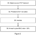
Figure 3 is a flow diagram showing alternative exemplary steps. - The following description refers to substitutional nitrogen in the crystal lattice of diamond. This type of diamond is commonly termed type 1 diamond, and the nitrogen typically occupies positions in the crystal lattice in one of three main configurations. Nitrogen can form A centres, B centres of C centres. These types of nitrogen substitution are illustrated in
Figure 1 , which shows a diamond crystal lattice in two dimensions for clarity. Carbon atoms are denoted by black circles and nitrogen atoms are denoted by white circles. - An 'A' centre consists of a neutral nearest-neighbour pair of nitrogen atoms substituting for the carbon atoms. Diamond containing nitrogen predominantly in the A form is classed as Type laA.
Figure 1 shows a lattice with two A centres. - A 'B' centre is a carbon vacancy surrounded by four nitrogen atoms substituting for carbon atoms. Diamond containing nitrogen predominantly in the B form is classed as Type laB.
- A 'C' centre is a single substitutional nitrogen atom in the crystal lattice that has no ordered relationship to another substitutional nitrogen atom. Diamond containing nitrogen predominantly in the C form is classed as Type Ib.
- Type Ia diamonds can be colourless, brown, pink, and violet. Natural Type Ib diamonds can be deep yellow ("canary"), orange, brown or greenish. Type IIa and Type IIb diamond contain negligible nitrogen; some nitrogen is always present but in Type II diamond the levels are much lower than in Type I diamond. Type IIa and Type IIb diamond differ in that Type IIb diamond contains boron as an impurity. Type II diamonds vary from colourless to deep blue, pink or brown. The colour of a diamond is determined by the number, type and distribution of defects within the crystal structure. Colour can also be introduced if there is a fine dispersion of metallic particles in the diamond material. Crystal defects include dislocations, microcracks, twin boundaries, point defects, and low angle boundaries. As such, for example, the colour of diamond will depend on the type and distribution of impurities such as nitrogen and boron as well as the type and distribution of other defects such as dislocations. There are a large number of different types and subclasses of defects within diamond. For example, there are numerous different types of nitrogen defect alone, each having its own spectral characteristics.
- The term 'aggregated nitrogen centre' is used herein to denote all types of nitrogen centre other than C centres. These are predominantly A and B centres, but the skilled person will appreciate that there are other types of centre where a nitrogen atom is located in the crystal lattice adjacent to another nitrogen atom or a vacancy or a combination of any number of these.
-
Figure 2 shows the basic steps involved in performing a method of making an embodiment of the present invention. The following numbering corresponds to that ofFigure 2 : - S1. A source High-Pressure High Temperature (HPHT) diamond material 10 is selected. This is a single crystal HPHT diamond. The HPHT diamond material 10 may be high nitrogen HPHT diamond material. This can be prepared by, for example, doping the diamond synthesis source material with a transition metal nitride compound (such as iron nitride) or an organic nitrogen containing compound.
- S2. The diamond material 10 is irradiated with electrons (or another source, such as neutrons) to form an irradiated diamond material 12 with increased toughness and/or wear resistance. Irradiation may be formed at an elevated temperature, in one example between 50°C and 500°C. The diamond material may be cooled during the irradiation process. In different embodiments, the irradiating has an energy selected from 30 keV or greater; 0.1 MeV to 12 MeV; 0.5 MeV to 10 MeV; and 1 MeV to 8 MeV. A preferred energy is 4.5MeV. In different embodiments, a dose rate is selected from any of 1 × 10¹⁵ e-/cm2 or greater; 1 × 10¹⁶ e-/cm2 to 1 × 10¹⁹ e-/cm2; 1 × 10¹⁷ e-/cm2 to 1 × 10¹⁹ e-/cm2; and 2 × 10¹⁷ e-/cm2 to 1 × 10¹⁹ e-/cm2. Note that irradiation may be performed to any suitable depth up to and including the entire thickness of the diamond material 10.
- S3. The irradiated diamond material 12 is then annealed to form an annealed diamond material 14 in which the aggregated nitrogen centre to C-nitrogen centre ratio is greater than 30%. Annealing may take place at an elevated temperature of at least 800°C in a vacuum of better than 10-4 mbar or in a gas that is inert with respect to diamond at the annealing temperature, such as argon or nitrogen. An alternative annealing process is to use an HPHT process at a pressure of at least 4.5 GPa and a temperature of at least 1300°C.
- S4. The annealed diamond material 14 is then processed to form a diamond tool piece 16. Processing may be, for example, cutting to a shape using a laser or mechanical cutter. The diamond tool piece 16 may be brazed to a carrier to form a diamond tool. Examples of tools that have diamond tool pieces include wear parts, dressers, wire drawing dies, gauge stones; cutters and engraving tools.
- Note that steps S2, S3 and S4 can be carried out in any suitable order, and may be repeated. For example, the processing of step S4 could be carried out before the irradiation of S2 and the annealing of S3, or could be carried out between the irradiation step of S2 and the annealing step of S3. Similarly, more than one irradiation step S2 or annealing step S3 may be used in order to apply different treatments such as radiation energy or dose, and for different amounts of time. The skilled person will appreciate that the steps may be performed in any suitable order, but by way of example,
Figure 3 shows an alternative order, with the following numbering corresponding to that ofFigure 3 . - S5.
- A source HPHT diamond material 10 is selected.
- S6.
- The source HPHT diamond material is processed to form a diamond tool piece.
- S7.
- The diamond tool piece is irradiated.
- S8.
- The irradiated diamond tool piece is annealed.
- Electron irradiation (for example, less than or equal to 12 MeV) typically introduces vacancies in an isolated form. These may be in the neutral (V0) and negative charge states (V-). The total vacancy concentration ([VT] = [V0] + [V-]) post irradiation should preferably be in the range: 1 × 10¹⁴ to 1 × 10²² vacancies/cm-3; 1 × 10¹⁵ to 1 × 10²¹ vacancies/cm-3; 5×10¹⁵ to 1 × 10²⁰ vacancies/cm-3; 1 × 10¹⁶ to 5 × 10¹⁹ vacancies/cm-3; or 5 × 10¹⁶ to 1 × 10¹⁹ vacancies/cm-3. An iterative process can be used to find optimum defect levels. A diamond material can be irradiated, tested, re-irradiated, and so on to find the optimum defect levels for a particular diamond material for a particular type of tool piece and tool application.
- Electron irradiation is typically carried out with a beam source in the energy range 0.1 MeV to 12 MeV. The preferred energy is that which introduces a near uniform concentration of vacancies in a nitrogen doped diamond, while minimizing the formation of cascade damage e.g. vacancy chains. It has been found that 4.5 MeV provides a good compromise between these two factors.
- Factors such as diamond temperature, beam energy, beam flux, and the starting diamond's properties can affect the [VT] produced for a fixed experimental irradiation set-up and time. Irradiation is typically carried out with the sample mounted under ambient conditions -300 K with only minimal temperature rise during the irradiation dose (e.g. less than 100 K). However, factors such as beam energy and beam flux can lead to sample heating. Preferably the sample is held as cold as possible (with even cryogenic cooling at 77 K being advantageous under some circumstances) to enable high dose rates without compromising temperature control and thus minimize the irradiation time. This is advantageous for commercial reasons.
- The vacancy concentration can be measured spectroscopically. For example, to measure concentrations of isolated vacancies, spectra are obtained at 77 K, using liquid nitrogen to cool the samples, since at that temperature sharp peaks at 741 nm and 394 nm are seen that are attributable to neutral and negatively charged isolated vacancies respectively. The coefficients that are used for the calculations of concentrations of isolated vacancies in the present specification are those set out by G. Davies in Physica B 273-274 (1999) 15-23, as detailed in Table 1 below. In Table 1, "A" is the integrated absorption (meV cm-1) in the zero phonon line of the transition, measured at 77 K, with the absorption coefficient in cm-1 and the photon energy in meV. The concentration is in cm-3.
TABLE 1 Defect Calibration V- AND1 = (4.8 ± 0.2) × 10-16[V-] v0 AGR1 = (1.2 ± 0.3) × 10-16[V0] - Note that while the above description of irradiation refers to electron irradiation, it is possible to introduce vacancies using neutron irradiation. It is also theoretically possible to create an HPHT diamond tool piece with an aggregated nitrogen centre to C nitrogen centre ratio of greater than 30% without using an irradiation step at all. However, this would require much more time or much higher temperatures to achieve.
- Once vacancies have been introduced by irradiation, the irradiated diamond material 12 is annealed. Annealing makes the vacancies more mobile within the diamond crystal lattice, and a vacancy may be replaced by a substitutional nitrogen. As described above, substitutional nitrogen atoms in the crystal may form predominantly A centres, B centres or C centres. As mentioned above, annealing may be done above 800°C in a vacuum or using an HPHT process. A typical annealing treatment is a two-step process with a first annealing treatment at 800°C in a vacuum and a second annealing treatment at 1500°C in a vacuum.
- It has been found that diamond material treated as described above such that the aggregated nitrogen centre to C-centre ratio is greater than 30% improves the wear resistance and toughness of the diamond material, making it suitable for use as a tool. A possible reason for the improvement in properties is that the aggregated nitrogen centres reduce lattice strain in the diamond compared to a diamond crystal lattice consisting only of C-centres. It will be appreciated that the both time and temperature of annealing will influence the ratio of aggregated nitrogen centres to C-centres.
- The diamond material used in embodiments of the present invention is HPHT diamond. It will be understood that natural diamond, HPHT diamond and Chemical Vapour Deposition (CVD) diamond have their own distinctive structural and functional characteristics and thus the terms "natural", "HPHT" and "CVD" not only refer to the method of formation of the diamond material but also refer to specific structural and functional characteristics of the materials themselves. For example, a synthetic CVD diamond material may be unequivocally distinguished from a synthetic diamond material synthesized using HPHT techniques by the dislocation structure. In synthetic CVD diamond, dislocations generally thread in a direction that is roughly perpendicular to the initial growth surface of the substrate, i.e. where the substrate is a (001) substrate, the dislocations are approximately aligned parallel to the [001] direction. In synthetic diamond material synthesized using HPHT techniques, dislocations that nucleate on surface of the seed crystal (often a surface close to {001}) typically grow in <110> directions. Thus the two types of material can be distinguished by their different dislocation structures observed, for example, in an X-ray topograph.
- HPHT diamond material may also be positively distinguished from natural or CVD diamond by detecting the presence of metallic inclusions. Metallic inclusions are incorporated into HPHT diamond as a result of the synthesis process, the metallic inclusions originating from metals used as the solvent catalyst metal, e.g. iron, cobalt, or nickel etc. These inclusions can vary in size, typically from less than 1 µm to more than 100 µm. Larger inclusions within that size range may be observed using a stereo-microscope (e.g. a Zeiss DV4); whilst smaller inclusions within that size range may be observed using transmitted light in a metallurgical microscope (e.g. a Zeiss "Axiophot").
- A further method that can be used to provide positive distinction between synthetic diamonds produced by CVD and HPHT methods is photoluminescence spectroscopy (PL). In the case of HPHT-synthesised material, defects containing atoms from the catalyst metals (typically transition metals) used in the synthesis process (e.g. nickel, cobalt, or iron etc.) are frequently present and the detection of such defects by PL positively indicates that the material has been synthesised by an HPHT method.
- The tools formed by embodiments of the present invention may be used for a range of applications including cutting, grinding, polishing, drilling and/or wire drawing.
- The diamond material in the tool may be configured into a number of possible crystallographic orientations including 2-point, 3-point and 4-point crystals which correspond to {110}, {111} and {100} crystallographic planes respectively. Particularly good results have been obtained for 3-point HPHT Type Ib diamond in a wire drawing tool and 2-point HPHT Type Ib diamond in a cutting tool. Optionally, the working surface of the diamond tool piece is formed by a single sector of diamond material.
- In some embodiments, the portion of the HPHT diamond tool piece with the aggregated nitrogen to C centre ratio of greater than 30% has a nitrogen content in the diamond lattice of greater than 300 parts per million (ppm), greater than 350 ppm or greater than 400 ppm. The nitrogen content in some embodiments is no greater than 800 ppm or no greater than 600 ppm. Nitrogen contents from 0 to 500 ppm have been tested and found to give improved wear rate and hardness after the irradiation and annealing steps.
- Several samples were made, each from a HPHT single crystal. Various irradiation doses and annealing treatments were used, as described below. These were analysed to determine the concentration of nitrogen, and the percentage of aggregated nitrogen centres. Furthermore, some of the samples were tested for wear resistance and chipping resistance, to determine the effect of the ration of aggregated nitrogen centres to C-centres on the mechanical properties of a tool made from the irradiated and annealed HPHT single crystal.
- The examples were all synthesized using an HPHT process at temperatures of between 1300 and 1500°C and pressures above 5 GPa. It will be appreciated that other HPHT temperature and pressures could be used. In some cases, the synthesis solvent included one or more nitrogen compounds in order to raise the concentration of nitrogen in the as-synthesized HPHT single crystal diamond.
- The nitrogen defect concentrations were determined using infrared spectroscopy, fitting peak intensities and using an appropriate proportionality constant, as is well known to the person of skill in the art.
- Wear resistance and chipping resistance were measured in a turning test on an Al-SiC metal matrix composite (25% volume fraction of 20 µm particles). The depth of the cut was 150 µm. The cutting speed was 500 m/min and the feed rate was 0.3 mm/rev. The wear resistance was considered to be the inverse of the increase in cutting force per meter of material cut. The chipping resistance was determined from the tools after the test with an optical microscope and is the inverse of the smallest distance between two edge chips. Rather than providing absolute values, the values for wear resistance and chipping resistance are presented as a fraction of normalised values for a single crystal HPHT diamond tool that has undergone no irradiation or annealing.
- Note that HPHT single crystal diamonds grown at different orientations were used. Typically, a single crystal diamond with a (100) orientation is used in cutting applications, and a single crystal with a (111) orientation is used in wire die applications.
- Table 2 shows that effect of irradiation and annealing regimes on the concentration of A-centres to C-centres for samples with a (111) orientation. A-centres were measured as these are by far the great majority of aggregated nitrogen centres, but note that other aggregated centres such as B-centres may be present. Annealing was either performed in a vacuum better than 10-6 mbar or in an HPHT process. In some cases the vacuum anneal was performed as a two stage process at two different dwell temperatures.
TABLE 2 Example Irradiation Vacuum anneal HPHT anneal Nitrogen defect 1 (outside invention) - - - 135 ppm 0% A 2 (outside invention) - 5 hr 1500 °C - 105 ppm 0% A 3 4.5 MeV 2 hr 800 °C - 92 ppm outside invention) 9 1016 e-/cm2 7% A 4 4.5 MeV 5 hr 1500 °C - 163 ppm (outside invention) 9 1016 e-/cm2 20% A 5 4.5 MeV 2.5 hr 1500 °C - 125 ppm (inside invention) 9 1016 e-/cm2 31% A 6 4.5 MeV 2 hr 900 °C - 59 ppm (inside invention) 9 1016 e-/cm2 5 hr 1500 °C 46% A 7 4.5 MeV 2 hr 800 °C - 131 ppm (inside invention) 9 1016 e-/cm2 5 hr 1550 °C 46% A 8 - - 2min 1900 °C 150 ppm (outside invention) 8 GPa 3% A 9 - - 1 hr 1900 °C 113 ppm (inside invention) 8 GPa 49% A 10 4.5 MeV - 2min 1900 °C 103 ppm (inside invention) 9 1016 e-/cm2 8 GPa 42% A 11 4.5 MeV - 1 hr 1900 °C 170 ppm (outside invention) 9 1016 e-/cm2 8 GPa 9% A 12 4.5 MeV 2 hr 800 °C - 405 ppm (inside invention) 3 1017 e-/cm2 5 hr 1500 °C 59% A - It can be seen that Example 1, with no irradiation or annealing, had a nitrogen concentration of 135 ppm with substantially no A-centres. Example 2, which was annealed but not irradiated, also showed substantially no A-centres. Examples 5, 6 and 7 which were vacuum annealed at two different temperatures, showed a greater proportion of A-centres than example 3 and 4, which were vacuum annealed in a single stage process. The HPHT annealed samples also displayed a high ration of A-centres.
- Table 3 shows the effect of irradiation and vacuum annealing on mechanical properties of (100) oriented single crystal HPHT diamonds, measured as normalised values against a comparable sample that had not undergone irradiation or annealing.
TABLE 3 Ex Irradiation Vacuum anneal Nitrogen defect Normalised wear resistance Normalised chipping resistance 13 - - 214 ppm 1.0 1.0 (outside invention) 0% A 14 4.5 MeV 2 hr 800 °C 153 ppm 1.3 (inside invention) 9 1016 e- /cm2 5 hr 1500 °C 35% A 15 4.5 MeV 2 hr 800 °C 137 ppm 1.3 1.1 (inside invention) 3 1017 e- /cm2 5 hr 1500 °C 50% A 16 4.5 MeV 2 hr 800 °C 463 ppm 5.3 3.7 (inside invention) 9 1016 e- /cm2 5 hr 1500 °C 47% A 17 4.5 MeV 2 hr 800 °C 461 ppm 1.9 1.3 (inside invention) 9 1016 e- /cm2 5 hr 1500 °C 46% A 18 4.5 MeV 2 hr 800 °C 515 ppm 2.3 2.1 (inside invention) 3 1017 e- /cm2 5 hr 1500 °C 66% A 19 4.5 MeV 2 hr 800 °C 388 ppm 3 2.2 (inside invention) 3 1017 e- /cm2 5 hr 1500 °C 61% A - Wear resistance and chipping resistance are improved by irradiation and subsequent annealing to engineer HPHT single crystal diamond with a high ration of A centres to C centres. It appears that higher nitrogen concentrations also give improved mechanical properties. However, nitrogen contents above around 800ppm can be difficult to synthesize under normal HPHT conditions.
Claims (4)
- A synthetic high-pressure high-temperature, HPHT, diamond tool piece, wherein at least a portion of the HPHT diamond tool piece comprises an aggregated nitrogen centre to C-nitrogen centre ratio of greater than 30%, the portion being at least 40% of the volume of the HPHT diamond tool piece, the aggregated nitrogen centres comprising A centres and B centres, wherein the HPHT diamond tool piece is a single crystal HPHT diamond tool piece selected from one of: a wear part, a dresser, a wire drawing die, a gauge stone, a cutter and an engraving tool.
- The synthetic HPHT diamond tool piece according to claim 1, wherein the portion of the HPHT diamond tool piece comprises a nitrogen content selected from any of greater than 300 parts per million, greater than 350 parts per million and greater than 400 parts per million.
- The synthetic HPHT diamond tool piece according to claim 1 or 2, wherein the portion of the HPHT diamond tool piece comprises a nitrogen content selected from any of no greater than 800 parts per million; and no greater than 600 parts per million.
- The synthetic HPHT diamond tool piece according to any one of claims 1 to 3, wherein the aggregated nitrogen centre to C-nitrogen centre ratio is greater than 40%.
Applications Claiming Priority (2)
| Application Number | Priority Date | Filing Date | Title |
|---|---|---|---|
| GBGB1608669.6A GB201608669D0 (en) | 2016-05-17 | 2016-05-17 | Diamond tool piece |
| PCT/EP2017/061722 WO2017198662A1 (en) | 2016-05-17 | 2017-05-16 | Diamond tool piece |
Publications (2)
| Publication Number | Publication Date |
|---|---|
| EP3458186A1 EP3458186A1 (en) | 2019-03-27 |
| EP3458186B1 true EP3458186B1 (en) | 2022-12-14 |
Family
ID=56320545
Family Applications (1)
| Application Number | Title | Priority Date | Filing Date |
|---|---|---|---|
| EP17725553.6A Active EP3458186B1 (en) | 2016-05-17 | 2017-05-16 | Diamond tool piece |
Country Status (7)
| Country | Link |
|---|---|
| US (1) | US11253925B2 (en) |
| EP (1) | EP3458186B1 (en) |
| JP (1) | JP6728395B2 (en) |
| KR (1) | KR102148362B1 (en) |
| CN (1) | CN109152998B (en) |
| GB (2) | GB201608669D0 (en) |
| WO (1) | WO2017198662A1 (en) |
Cited By (3)
| Publication number | Priority date | Publication date | Assignee | Title |
|---|---|---|---|---|
| USD1026982S1 (en) | 2019-01-11 | 2024-05-14 | Us Synthetic Corporation | Cutting tool |
| USD1026979S1 (en) | 2020-12-03 | 2024-05-14 | Us Synthetic Corporation | Cutting tool |
| USD1131560S1 (en) | 2023-01-09 | 2026-06-23 | Us Synthetic Corporation | Cutting tool |
Families Citing this family (8)
| Publication number | Priority date | Publication date | Assignee | Title |
|---|---|---|---|---|
| DE102017204109B4 (en) * | 2017-03-13 | 2019-03-14 | Gühring KG | Use of a doped with foreign atoms diamond layer for detecting the degree of wear of an undoped diamond functional layer of a tool |
| CN109796223A (en) * | 2019-01-23 | 2019-05-24 | 太原科技大学 | The method that silicon vacancy defect and GR1 neutrality vacancy defect mutually convert in diamond |
| GB201918378D0 (en) * | 2019-12-13 | 2020-01-29 | Element Six Uk Ltd | Polycrystalline diamond with iron-containing binder |
| CN111360362B (en) * | 2020-04-01 | 2021-11-16 | 中国科学院理化技术研究所 | Deep cooling treatment method for brazing diamond tool and brazing diamond tool |
| WO2022004150A1 (en) * | 2020-06-30 | 2022-01-06 | 住友電気工業株式会社 | Synthetic single-crystal diamond and manufacturing method thereof |
| JP7755109B1 (en) * | 2024-02-16 | 2025-10-15 | 住友電気工業株式会社 | Single crystal diamond and tool including same |
| WO2025173238A1 (en) * | 2024-02-16 | 2025-08-21 | 住友電気工業株式会社 | Single crystal diamond and tool |
| JP7760754B1 (en) * | 2024-02-16 | 2025-10-27 | 住友電気工業株式会社 | Single crystal diamond materials and tools |
Family Cites Families (16)
| Publication number | Priority date | Publication date | Assignee | Title |
|---|---|---|---|---|
| ZA741183B (en) | 1974-02-22 | 1975-10-29 | De Beers Ind Diamond | Abrasive particles |
| IE45102B1 (en) | 1976-07-21 | 1982-06-16 | Gen Electric | Process for converting type ib nitrogen in a diamond crystal into type ia nitrogen |
| GB1588445A (en) | 1977-05-26 | 1981-04-23 | Nat Res Dev | Toughening diamond |
| GB1588418A (en) | 1978-05-17 | 1981-04-23 | Atomic Energy Authority Uk | Artefacts incorporating industrial diamonds |
| JPH0288498A (en) | 1988-06-13 | 1990-03-28 | Sumitomo Electric Ind Ltd | Diamond laser crystal and its manufacturing method |
| KR940014144A (en) * | 1992-01-22 | 1994-07-16 | 하지메 히토추야나기 | Manufacturing method of diamond single crystal |
| US6377340B1 (en) * | 1999-10-29 | 2002-04-23 | General Electric Company | Method of detection of natural diamonds that have been processed at high pressure and high temperatures |
| WO2001079583A2 (en) | 2000-04-14 | 2001-10-25 | Technology International, Inc. | Diamonds having improved durability |
| RU2237113C1 (en) * | 2003-06-26 | 2004-09-27 | Винс Виктор Генрихович | Method of manufacturing diamonds in fantasy red color |
| DE602006021467D1 (en) * | 2005-12-09 | 2011-06-01 | Element Six Technologies Pty Ltd | SYNTHETIC DIAMOND WITH HIGH CRYSTALLINE QUALITY |
| WO2008007336A2 (en) | 2006-07-10 | 2008-01-17 | Element Six Technologies (Pty) Ltd | A method for producing diamond material |
| CN102939261B (en) | 2010-06-03 | 2015-09-23 | 六号元素有限公司 | Diamond tool |
| GB2492822A (en) | 2011-07-14 | 2013-01-16 | Element Six Ltd | Modifying diamond components by irradiation |
| US9089951B2 (en) | 2011-08-23 | 2015-07-28 | Element Six Limited | Fine polycrystalline diamond compact with a grain growth inhibitor layer between diamond and substrate |
| JP5914041B2 (en) * | 2012-02-28 | 2016-05-11 | 株式会社栗田製作所 | Single crystal diamond manufacturing method and single crystal diamond manufacturing apparatus |
| EP3170926B1 (en) | 2014-07-15 | 2025-02-12 | Sumitomo Electric Industries, Ltd. | Single crystal diamond, method for producing single crystal diamond, and tool using single crystal diamond |
-
2016
- 2016-05-17 GB GBGB1608669.6A patent/GB201608669D0/en not_active Ceased
-
2017
- 2017-05-16 WO PCT/EP2017/061722 patent/WO2017198662A1/en not_active Ceased
- 2017-05-16 KR KR1020187033188A patent/KR102148362B1/en active Active
- 2017-05-16 GB GB1707827.0A patent/GB2550689B/en active Active
- 2017-05-16 CN CN201780029965.5A patent/CN109152998B/en active Active
- 2017-05-16 EP EP17725553.6A patent/EP3458186B1/en active Active
- 2017-05-16 US US16/090,935 patent/US11253925B2/en active Active
- 2017-05-16 JP JP2018555726A patent/JP6728395B2/en active Active
Cited By (4)
| Publication number | Priority date | Publication date | Assignee | Title |
|---|---|---|---|---|
| USD1026982S1 (en) | 2019-01-11 | 2024-05-14 | Us Synthetic Corporation | Cutting tool |
| USD1026979S1 (en) | 2020-12-03 | 2024-05-14 | Us Synthetic Corporation | Cutting tool |
| USD1112387S1 (en) | 2020-12-03 | 2026-02-10 | Us Synthetic Corporation | Cutting tool |
| USD1131560S1 (en) | 2023-01-09 | 2026-06-23 | Us Synthetic Corporation | Cutting tool |
Also Published As
| Publication number | Publication date |
|---|---|
| CN109152998B (en) | 2021-12-07 |
| EP3458186A1 (en) | 2019-03-27 |
| CN109152998A (en) | 2019-01-04 |
| US11253925B2 (en) | 2022-02-22 |
| GB201608669D0 (en) | 2016-06-29 |
| US20190118150A1 (en) | 2019-04-25 |
| JP6728395B2 (en) | 2020-07-22 |
| JP2019523741A (en) | 2019-08-29 |
| WO2017198662A1 (en) | 2017-11-23 |
| GB201707827D0 (en) | 2017-06-28 |
| GB2550689B (en) | 2020-12-30 |
| KR102148362B1 (en) | 2020-08-26 |
| GB2550689A (en) | 2017-11-29 |
| KR20180135005A (en) | 2018-12-19 |
Similar Documents
| Publication | Publication Date | Title |
|---|---|---|
| US11253925B2 (en) | Diamond tool piece | |
| EP2576441B1 (en) | Diamond tools | |
| EP2446070B1 (en) | Method for making fancy pale blue or fancy pale blue/green single crystal cvd diamond and product obtained | |
| Liang et al. | Enhancing the mechanical properties of single-crystal CVD diamond | |
| GB2492822A (en) | Modifying diamond components by irradiation | |
| HK1170273B (en) | Method for making fancy pale blue or fancy pale blue / green single crystal cvd diamond and product obtained | |
| HK1170273A (en) | Method for making fancy pale blue or fancy pale blue / green single crystal cvd diamond and product obtained |
Legal Events
| Date | Code | Title | Description |
|---|---|---|---|
| STAA | Information on the status of an ep patent application or granted ep patent |
Free format text: STATUS: UNKNOWN |
|
| STAA | Information on the status of an ep patent application or granted ep patent |
Free format text: STATUS: THE INTERNATIONAL PUBLICATION HAS BEEN MADE |
|
| PUAI | Public reference made under article 153(3) epc to a published international application that has entered the european phase |
Free format text: ORIGINAL CODE: 0009012 |
|
| STAA | Information on the status of an ep patent application or granted ep patent |
Free format text: STATUS: REQUEST FOR EXAMINATION WAS MADE |
|
| 17P | Request for examination filed |
Effective date: 20181002 |
|
| AK | Designated contracting states |
Kind code of ref document: A1 Designated state(s): AL AT BE BG CH CY CZ DE DK EE ES FI FR GB GR HR HU IE IS IT LI LT LU LV MC MK MT NL NO PL PT RO RS SE SI SK SM TR |
|
| AX | Request for extension of the european patent |
Extension state: BA ME |
|
| DAV | Request for validation of the european patent (deleted) | ||
| DAX | Request for extension of the european patent (deleted) | ||
| STAA | Information on the status of an ep patent application or granted ep patent |
Free format text: STATUS: EXAMINATION IS IN PROGRESS |
|
| 17Q | First examination report despatched |
Effective date: 20190906 |
|
| REG | Reference to a national code |
Ref country code: DE Ref legal event code: R079 Ref document number: 602017064574 Country of ref document: DE Free format text: PREVIOUS MAIN CLASS: B01J0003060000 Ipc: B23B0027200000 |
|
| GRAP | Despatch of communication of intention to grant a patent |
Free format text: ORIGINAL CODE: EPIDOSNIGR1 |
|
| STAA | Information on the status of an ep patent application or granted ep patent |
Free format text: STATUS: GRANT OF PATENT IS INTENDED |
|
| RIC1 | Information provided on ipc code assigned before grant |
Ipc: C30B 33/04 20060101ALI20220721BHEP Ipc: C30B 29/04 20060101ALI20220721BHEP Ipc: B01J 3/06 20060101ALI20220721BHEP Ipc: B23B 27/20 20060101AFI20220721BHEP |
|
| INTG | Intention to grant announced |
Effective date: 20220808 |
|
| GRAS | Grant fee paid |
Free format text: ORIGINAL CODE: EPIDOSNIGR3 |
|
| GRAA | (expected) grant |
Free format text: ORIGINAL CODE: 0009210 |
|
| STAA | Information on the status of an ep patent application or granted ep patent |
Free format text: STATUS: THE PATENT HAS BEEN GRANTED |
|
| AK | Designated contracting states |
Kind code of ref document: B1 Designated state(s): AL AT BE BG CH CY CZ DE DK EE ES FI FR GB GR HR HU IE IS IT LI LT LU LV MC MK MT NL NO PL PT RO RS SE SI SK SM TR |
|
| REG | Reference to a national code |
Ref country code: GB Ref legal event code: FG4D |
|
| REG | Reference to a national code |
Ref country code: CH Ref legal event code: EP |
|
| REG | Reference to a national code |
Ref country code: DE Ref legal event code: R096 Ref document number: 602017064574 Country of ref document: DE |
|
| REG | Reference to a national code |
Ref country code: IE Ref legal event code: FG4D |
|
| REG | Reference to a national code |
Ref country code: AT Ref legal event code: REF Ref document number: 1537379 Country of ref document: AT Kind code of ref document: T Effective date: 20230115 |
|
| REG | Reference to a national code |
Ref country code: NL Ref legal event code: FP |
|
| REG | Reference to a national code |
Ref country code: LT Ref legal event code: MG9D |
|
| PG25 | Lapsed in a contracting state [announced via postgrant information from national office to epo] |
Ref country code: SE Free format text: LAPSE BECAUSE OF FAILURE TO SUBMIT A TRANSLATION OF THE DESCRIPTION OR TO PAY THE FEE WITHIN THE PRESCRIBED TIME-LIMIT Effective date: 20221214 Ref country code: NO Free format text: LAPSE BECAUSE OF FAILURE TO SUBMIT A TRANSLATION OF THE DESCRIPTION OR TO PAY THE FEE WITHIN THE PRESCRIBED TIME-LIMIT Effective date: 20230314 Ref country code: LT Free format text: LAPSE BECAUSE OF FAILURE TO SUBMIT A TRANSLATION OF THE DESCRIPTION OR TO PAY THE FEE WITHIN THE PRESCRIBED TIME-LIMIT Effective date: 20221214 Ref country code: FI Free format text: LAPSE BECAUSE OF FAILURE TO SUBMIT A TRANSLATION OF THE DESCRIPTION OR TO PAY THE FEE WITHIN THE PRESCRIBED TIME-LIMIT Effective date: 20221214 |
|
| REG | Reference to a national code |
Ref country code: AT Ref legal event code: MK05 Ref document number: 1537379 Country of ref document: AT Kind code of ref document: T Effective date: 20221214 |
|
| PG25 | Lapsed in a contracting state [announced via postgrant information from national office to epo] |
Ref country code: RS Free format text: LAPSE BECAUSE OF FAILURE TO SUBMIT A TRANSLATION OF THE DESCRIPTION OR TO PAY THE FEE WITHIN THE PRESCRIBED TIME-LIMIT Effective date: 20221214 Ref country code: LV Free format text: LAPSE BECAUSE OF FAILURE TO SUBMIT A TRANSLATION OF THE DESCRIPTION OR TO PAY THE FEE WITHIN THE PRESCRIBED TIME-LIMIT Effective date: 20221214 Ref country code: HR Free format text: LAPSE BECAUSE OF FAILURE TO SUBMIT A TRANSLATION OF THE DESCRIPTION OR TO PAY THE FEE WITHIN THE PRESCRIBED TIME-LIMIT Effective date: 20221214 Ref country code: GR Free format text: LAPSE BECAUSE OF FAILURE TO SUBMIT A TRANSLATION OF THE DESCRIPTION OR TO PAY THE FEE WITHIN THE PRESCRIBED TIME-LIMIT Effective date: 20230315 |
|
| P01 | Opt-out of the competence of the unified patent court (upc) registered |
Effective date: 20230524 |
|
| PG25 | Lapsed in a contracting state [announced via postgrant information from national office to epo] |
Ref country code: SM Free format text: LAPSE BECAUSE OF FAILURE TO SUBMIT A TRANSLATION OF THE DESCRIPTION OR TO PAY THE FEE WITHIN THE PRESCRIBED TIME-LIMIT Effective date: 20221214 Ref country code: RO Free format text: LAPSE BECAUSE OF FAILURE TO SUBMIT A TRANSLATION OF THE DESCRIPTION OR TO PAY THE FEE WITHIN THE PRESCRIBED TIME-LIMIT Effective date: 20221214 Ref country code: PT Free format text: LAPSE BECAUSE OF FAILURE TO SUBMIT A TRANSLATION OF THE DESCRIPTION OR TO PAY THE FEE WITHIN THE PRESCRIBED TIME-LIMIT Effective date: 20230414 Ref country code: ES Free format text: LAPSE BECAUSE OF FAILURE TO SUBMIT A TRANSLATION OF THE DESCRIPTION OR TO PAY THE FEE WITHIN THE PRESCRIBED TIME-LIMIT Effective date: 20221214 Ref country code: EE Free format text: LAPSE BECAUSE OF FAILURE TO SUBMIT A TRANSLATION OF THE DESCRIPTION OR TO PAY THE FEE WITHIN THE PRESCRIBED TIME-LIMIT Effective date: 20221214 Ref country code: CZ Free format text: LAPSE BECAUSE OF FAILURE TO SUBMIT A TRANSLATION OF THE DESCRIPTION OR TO PAY THE FEE WITHIN THE PRESCRIBED TIME-LIMIT Effective date: 20221214 Ref country code: AT Free format text: LAPSE BECAUSE OF FAILURE TO SUBMIT A TRANSLATION OF THE DESCRIPTION OR TO PAY THE FEE WITHIN THE PRESCRIBED TIME-LIMIT Effective date: 20221214 |
|
| PG25 | Lapsed in a contracting state [announced via postgrant information from national office to epo] |
Ref country code: SK Free format text: LAPSE BECAUSE OF FAILURE TO SUBMIT A TRANSLATION OF THE DESCRIPTION OR TO PAY THE FEE WITHIN THE PRESCRIBED TIME-LIMIT Effective date: 20221214 Ref country code: PL Free format text: LAPSE BECAUSE OF FAILURE TO SUBMIT A TRANSLATION OF THE DESCRIPTION OR TO PAY THE FEE WITHIN THE PRESCRIBED TIME-LIMIT Effective date: 20221214 Ref country code: IS Free format text: LAPSE BECAUSE OF FAILURE TO SUBMIT A TRANSLATION OF THE DESCRIPTION OR TO PAY THE FEE WITHIN THE PRESCRIBED TIME-LIMIT Effective date: 20230414 Ref country code: AL Free format text: LAPSE BECAUSE OF FAILURE TO SUBMIT A TRANSLATION OF THE DESCRIPTION OR TO PAY THE FEE WITHIN THE PRESCRIBED TIME-LIMIT Effective date: 20221214 |
|
| REG | Reference to a national code |
Ref country code: DE Ref legal event code: R097 Ref document number: 602017064574 Country of ref document: DE |
|
| PLBE | No opposition filed within time limit |
Free format text: ORIGINAL CODE: 0009261 |
|
| STAA | Information on the status of an ep patent application or granted ep patent |
Free format text: STATUS: NO OPPOSITION FILED WITHIN TIME LIMIT |
|
| PG25 | Lapsed in a contracting state [announced via postgrant information from national office to epo] |
Ref country code: DK Free format text: LAPSE BECAUSE OF FAILURE TO SUBMIT A TRANSLATION OF THE DESCRIPTION OR TO PAY THE FEE WITHIN THE PRESCRIBED TIME-LIMIT Effective date: 20221214 |
|
| 26N | No opposition filed |
Effective date: 20230915 |
|
| PG25 | Lapsed in a contracting state [announced via postgrant information from national office to epo] |
Ref country code: SI Free format text: LAPSE BECAUSE OF FAILURE TO SUBMIT A TRANSLATION OF THE DESCRIPTION OR TO PAY THE FEE WITHIN THE PRESCRIBED TIME-LIMIT Effective date: 20221214 |
|
| REG | Reference to a national code |
Ref country code: CH Ref legal event code: PL |
|
| PG25 | Lapsed in a contracting state [announced via postgrant information from national office to epo] |
Ref country code: MC Free format text: LAPSE BECAUSE OF FAILURE TO SUBMIT A TRANSLATION OF THE DESCRIPTION OR TO PAY THE FEE WITHIN THE PRESCRIBED TIME-LIMIT Effective date: 20221214 |
|
| PG25 | Lapsed in a contracting state [announced via postgrant information from national office to epo] |
Ref country code: MC Free format text: LAPSE BECAUSE OF FAILURE TO SUBMIT A TRANSLATION OF THE DESCRIPTION OR TO PAY THE FEE WITHIN THE PRESCRIBED TIME-LIMIT Effective date: 20221214 Ref country code: LU Free format text: LAPSE BECAUSE OF NON-PAYMENT OF DUE FEES Effective date: 20230516 Ref country code: LI Free format text: LAPSE BECAUSE OF NON-PAYMENT OF DUE FEES Effective date: 20230531 Ref country code: CH Free format text: LAPSE BECAUSE OF NON-PAYMENT OF DUE FEES Effective date: 20230531 |
|
| REG | Reference to a national code |
Ref country code: IE Ref legal event code: MM4A |
|
| PG25 | Lapsed in a contracting state [announced via postgrant information from national office to epo] |
Ref country code: IE Free format text: LAPSE BECAUSE OF NON-PAYMENT OF DUE FEES Effective date: 20230516 |
|
| PG25 | Lapsed in a contracting state [announced via postgrant information from national office to epo] |
Ref country code: IE Free format text: LAPSE BECAUSE OF NON-PAYMENT OF DUE FEES Effective date: 20230516 |
|
| PG25 | Lapsed in a contracting state [announced via postgrant information from national office to epo] |
Ref country code: IT Free format text: LAPSE BECAUSE OF FAILURE TO SUBMIT A TRANSLATION OF THE DESCRIPTION OR TO PAY THE FEE WITHIN THE PRESCRIBED TIME-LIMIT Effective date: 20221214 Ref country code: FR Free format text: LAPSE BECAUSE OF NON-PAYMENT OF DUE FEES Effective date: 20230531 |
|
| PG25 | Lapsed in a contracting state [announced via postgrant information from national office to epo] |
Ref country code: BG Free format text: LAPSE BECAUSE OF FAILURE TO SUBMIT A TRANSLATION OF THE DESCRIPTION OR TO PAY THE FEE WITHIN THE PRESCRIBED TIME-LIMIT Effective date: 20221214 |
|
| PG25 | Lapsed in a contracting state [announced via postgrant information from national office to epo] |
Ref country code: BG Free format text: LAPSE BECAUSE OF FAILURE TO SUBMIT A TRANSLATION OF THE DESCRIPTION OR TO PAY THE FEE WITHIN THE PRESCRIBED TIME-LIMIT Effective date: 20221214 |
|
| PG25 | Lapsed in a contracting state [announced via postgrant information from national office to epo] |
Ref country code: CY Free format text: LAPSE BECAUSE OF FAILURE TO SUBMIT A TRANSLATION OF THE DESCRIPTION OR TO PAY THE FEE WITHIN THE PRESCRIBED TIME-LIMIT; INVALID AB INITIO Effective date: 20170516 |
|
| PG25 | Lapsed in a contracting state [announced via postgrant information from national office to epo] |
Ref country code: HU Free format text: LAPSE BECAUSE OF FAILURE TO SUBMIT A TRANSLATION OF THE DESCRIPTION OR TO PAY THE FEE WITHIN THE PRESCRIBED TIME-LIMIT; INVALID AB INITIO Effective date: 20170516 |
|
| PG25 | Lapsed in a contracting state [announced via postgrant information from national office to epo] |
Ref country code: TR Free format text: LAPSE BECAUSE OF FAILURE TO SUBMIT A TRANSLATION OF THE DESCRIPTION OR TO PAY THE FEE WITHIN THE PRESCRIBED TIME-LIMIT Effective date: 20221214 |
|
| PGFP | Annual fee paid to national office [announced via postgrant information from national office to epo] |
Ref country code: GB Payment date: 20260327 Year of fee payment: 10 |
|
| PGFP | Annual fee paid to national office [announced via postgrant information from national office to epo] |
Ref country code: NL Payment date: 20260526 Year of fee payment: 10 |
|
| PGFP | Annual fee paid to national office [announced via postgrant information from national office to epo] |
Ref country code: DE Payment date: 20260528 Year of fee payment: 10 |
|
| PGFP | Annual fee paid to national office [announced via postgrant information from national office to epo] |
Ref country code: BE Payment date: 20260527 Year of fee payment: 10 |