EP3457820A1 - Medical plasma-generating device and plasma irradiation method - Google Patents
Medical plasma-generating device and plasma irradiation method Download PDFInfo
- Publication number
- EP3457820A1 EP3457820A1 EP16901693.8A EP16901693A EP3457820A1 EP 3457820 A1 EP3457820 A1 EP 3457820A1 EP 16901693 A EP16901693 A EP 16901693A EP 3457820 A1 EP3457820 A1 EP 3457820A1
- Authority
- EP
- European Patent Office
- Prior art keywords
- plasma
- inert gas
- ejecting
- cylindrical section
- ejected
- Prior art date
- Legal status (The legal status is an assumption and is not a legal conclusion. Google has not performed a legal analysis and makes no representation as to the accuracy of the status listed.)
- Granted
Links
Images


Classifications
-
- A—HUMAN NECESSITIES
- A61—MEDICAL OR VETERINARY SCIENCE; HYGIENE
- A61N—ELECTROTHERAPY; MAGNETOTHERAPY; RADIATION THERAPY; ULTRASOUND THERAPY
- A61N5/00—Radiation therapy
-
- A—HUMAN NECESSITIES
- A61—MEDICAL OR VETERINARY SCIENCE; HYGIENE
- A61B—DIAGNOSIS; SURGERY; IDENTIFICATION
- A61B18/00—Surgical instruments, devices or methods for transferring non-mechanical forms of energy to or from the body
- A61B18/18—Surgical instruments, devices or methods for transferring non-mechanical forms of energy to or from the body by applying electromagnetic radiation, e.g. microwaves
-
- H—ELECTRICITY
- H05—ELECTRIC TECHNIQUES NOT OTHERWISE PROVIDED FOR
- H05H—PLASMA TECHNIQUE; PRODUCTION OF ACCELERATED ELECTRICALLY-CHARGED PARTICLES OR OF NEUTRONS; PRODUCTION OR ACCELERATION OF NEUTRAL MOLECULAR OR ATOMIC BEAMS
- H05H1/00—Generating plasma; Handling plasma
- H05H1/24—Generating plasma
-
- A—HUMAN NECESSITIES
- A61—MEDICAL OR VETERINARY SCIENCE; HYGIENE
- A61B—DIAGNOSIS; SURGERY; IDENTIFICATION
- A61B18/00—Surgical instruments, devices or methods for transferring non-mechanical forms of energy to or from the body
- A61B18/04—Surgical instruments, devices or methods for transferring non-mechanical forms of energy to or from the body by heating
- A61B18/042—Surgical instruments, devices or methods for transferring non-mechanical forms of energy to or from the body by heating using additional gas becoming plasma
-
- A—HUMAN NECESSITIES
- A61—MEDICAL OR VETERINARY SCIENCE; HYGIENE
- A61B—DIAGNOSIS; SURGERY; IDENTIFICATION
- A61B90/00—Instruments, implements or accessories specially adapted for surgery or diagnosis and not covered by any of the groups A61B1/00 - A61B50/00, e.g. for luxation treatment or for protecting wound edges
- A61B90/30—Devices for illuminating a surgical field, the devices having an interrelation with other surgical devices or with a surgical procedure
-
- A—HUMAN NECESSITIES
- A61—MEDICAL OR VETERINARY SCIENCE; HYGIENE
- A61N—ELECTROTHERAPY; MAGNETOTHERAPY; RADIATION THERAPY; ULTRASOUND THERAPY
- A61N1/00—Electrotherapy; Circuits therefor
- A61N1/44—Applying ionised fluids
-
- A—HUMAN NECESSITIES
- A61—MEDICAL OR VETERINARY SCIENCE; HYGIENE
- A61N—ELECTROTHERAPY; MAGNETOTHERAPY; RADIATION THERAPY; ULTRASOUND THERAPY
- A61N5/00—Radiation therapy
- A61N5/06—Radiation therapy using light
- A61N5/0613—Apparatus adapted for a specific treatment
- A61N5/0616—Skin treatment other than tanning
-
- A—HUMAN NECESSITIES
- A61—MEDICAL OR VETERINARY SCIENCE; HYGIENE
- A61N—ELECTROTHERAPY; MAGNETOTHERAPY; RADIATION THERAPY; ULTRASOUND THERAPY
- A61N5/00—Radiation therapy
- A61N5/10—X-ray therapy; Gamma-ray therapy; Particle-irradiation therapy
- A61N5/1048—Monitoring, verifying, controlling systems and methods
-
- H—ELECTRICITY
- H05—ELECTRIC TECHNIQUES NOT OTHERWISE PROVIDED FOR
- H05H—PLASMA TECHNIQUE; PRODUCTION OF ACCELERATED ELECTRICALLY-CHARGED PARTICLES OR OF NEUTRONS; PRODUCTION OR ACCELERATION OF NEUTRAL MOLECULAR OR ATOMIC BEAMS
- H05H1/00—Generating plasma; Handling plasma
- H05H1/24—Generating plasma
- H05H1/2406—Generating plasma using dielectric barrier discharges, i.e. with a dielectric interposed between the electrodes
- H05H1/2443—Generating plasma using dielectric barrier discharges, i.e. with a dielectric interposed between the electrodes the plasma fluid flowing through a dielectric tube
-
- H—ELECTRICITY
- H05—ELECTRIC TECHNIQUES NOT OTHERWISE PROVIDED FOR
- H05H—PLASMA TECHNIQUE; PRODUCTION OF ACCELERATED ELECTRICALLY-CHARGED PARTICLES OR OF NEUTRONS; PRODUCTION OR ACCELERATION OF NEUTRAL MOLECULAR OR ATOMIC BEAMS
- H05H1/00—Generating plasma; Handling plasma
- H05H1/24—Generating plasma
- H05H1/2406—Generating plasma using dielectric barrier discharges, i.e. with a dielectric interposed between the electrodes
- H05H1/2443—Generating plasma using dielectric barrier discharges, i.e. with a dielectric interposed between the electrodes the plasma fluid flowing through a dielectric tube
- H05H1/246—Generating plasma using dielectric barrier discharges, i.e. with a dielectric interposed between the electrodes the plasma fluid flowing through a dielectric tube the plasma being activated using external electrodes
-
- A—HUMAN NECESSITIES
- A61—MEDICAL OR VETERINARY SCIENCE; HYGIENE
- A61N—ELECTROTHERAPY; MAGNETOTHERAPY; RADIATION THERAPY; ULTRASOUND THERAPY
- A61N5/00—Radiation therapy
- A61N2005/002—Cooling systems
- A61N2005/005—Cooling systems for cooling the radiator
-
- A—HUMAN NECESSITIES
- A61—MEDICAL OR VETERINARY SCIENCE; HYGIENE
- A61N—ELECTROTHERAPY; MAGNETOTHERAPY; RADIATION THERAPY; ULTRASOUND THERAPY
- A61N5/00—Radiation therapy
- A61N2005/002—Cooling systems
- A61N2005/007—Cooling systems for cooling the patient
-
- A—HUMAN NECESSITIES
- A61—MEDICAL OR VETERINARY SCIENCE; HYGIENE
- A61N—ELECTROTHERAPY; MAGNETOTHERAPY; RADIATION THERAPY; ULTRASOUND THERAPY
- A61N5/00—Radiation therapy
- A61N5/10—X-ray therapy; Gamma-ray therapy; Particle-irradiation therapy
- A61N2005/1085—X-ray therapy; Gamma-ray therapy; Particle-irradiation therapy characterised by the type of particles applied to the patient
- A61N2005/1087—Ions; Protons
-
- H—ELECTRICITY
- H05—ELECTRIC TECHNIQUES NOT OTHERWISE PROVIDED FOR
- H05H—PLASMA TECHNIQUE; PRODUCTION OF ACCELERATED ELECTRICALLY-CHARGED PARTICLES OR OF NEUTRONS; PRODUCTION OR ACCELERATION OF NEUTRAL MOLECULAR OR ATOMIC BEAMS
- H05H2240/00—Testing
- H05H2240/10—Testing at atmospheric pressure
-
- H—ELECTRICITY
- H05—ELECTRIC TECHNIQUES NOT OTHERWISE PROVIDED FOR
- H05H—PLASMA TECHNIQUE; PRODUCTION OF ACCELERATED ELECTRICALLY-CHARGED PARTICLES OR OF NEUTRONS; PRODUCTION OR ACCELERATION OF NEUTRAL MOLECULAR OR ATOMIC BEAMS
- H05H2240/00—Testing
- H05H2240/20—Non-thermal plasma
-
- H—ELECTRICITY
- H05—ELECTRIC TECHNIQUES NOT OTHERWISE PROVIDED FOR
- H05H—PLASMA TECHNIQUE; PRODUCTION OF ACCELERATED ELECTRICALLY-CHARGED PARTICLES OR OF NEUTRONS; PRODUCTION OR ACCELERATION OF NEUTRAL MOLECULAR OR ATOMIC BEAMS
- H05H2245/00—Applications of plasma devices
- H05H2245/30—Medical applications
- H05H2245/32—Surgery, e.g. scalpels, blades or bistoury; Treatments inside the body
-
- H—ELECTRICITY
- H05—ELECTRIC TECHNIQUES NOT OTHERWISE PROVIDED FOR
- H05H—PLASMA TECHNIQUE; PRODUCTION OF ACCELERATED ELECTRICALLY-CHARGED PARTICLES OR OF NEUTRONS; PRODUCTION OR ACCELERATION OF NEUTRAL MOLECULAR OR ATOMIC BEAMS
- H05H2245/00—Applications of plasma devices
- H05H2245/30—Medical applications
- H05H2245/34—Skin treatments, e.g. disinfection or wound treatment
-
- H—ELECTRICITY
- H05—ELECTRIC TECHNIQUES NOT OTHERWISE PROVIDED FOR
- H05H—PLASMA TECHNIQUE; PRODUCTION OF ACCELERATED ELECTRICALLY-CHARGED PARTICLES OR OF NEUTRONS; PRODUCTION OR ACCELERATION OF NEUTRAL MOLECULAR OR ATOMIC BEAMS
- H05H2245/00—Applications of plasma devices
- H05H2245/60—Portable devices
Definitions
- the present invention relates to a medical-use plasma generating device and a plasma emitting method using the medical-use plasma generating device for use in plasma medical treatments.
- Plasma processing is performed by a plasma generating device ejecting plasma from an emission port towards a processing target such that plasma is applied to the processing target.
- a plasma generating device ejecting plasma from an emission port towards a processing target such that plasma is applied to the processing target. Examples of a plasma generating device is disclosed in the patent literature below.
- Plasma includes active radicals and research is progressing of emitting plasma for medical treatment purposes, wherein the surface of a processing body is activated by plasma being applied.
- oxygen plasma generated by using oxygen as a processing gas is effective for killing cells, and by applying oxygen plasma to cancerous cells, emitting of such plasma can be used for the purpose of cancer treatment.
- hydrogen plasma generated by using hydrogen as a processing gas is effective for regenerating cells, and by applying hydrogen plasma to skin, emitting of such plasma can be used for the purpose of skin regeneration treatment. In such ways, emitting of plasma is performed for medical treatment purposes, but for medical treatment, the concentration of the processing gas and so on is controlled strictly.
- the present invention takes account of such problems, and an object thereof is to provide a medical-use plasma generating device with high practicality.
- a medical-use plasma generating device of the present disclosure includes: a plasma ejecting device configured to eject plasma; and an inert gas ejecting device configured to eject an inert gas such that an outer circumference of the plasma ejected by the plasma ejecting device is covered by the inert gas.
- a plasma emitting method of the present disclosure is a plasma emitting method for applying plasma to a processing target using a medical-use plasma generating device provided with a plasma ejecting device configured to eject plasma, and an inert gas ejecting device configured to eject an inert gas such that an outer circumference of the plasma ejected by the plasma emitting device is covered by the inert gas, the plasma emitting method including: ejecting an inert gas using the inert gas ejecting device; and after ejecting the inert gas, ejecting plasma using the plasma ejecting device.
- inert gas is ejected to surround an outer circumference of ejected plasma.
- the ejected plasma is shielded by the inert gas such that the plasma can be applied to a processing target, that is, an affected body part, without being exposed to air. Accordingly, deactivation of the plasma by air is prevented, and plasma medical treatment can be performed without decreasing the effect that is expected based on a strictly managed concentration of the processing gas.
- plasma is ejected after the inert gas is ejected.
- inert gas is ejected to cover the plasma emission port, meaning that the plasma is ejected through the inert gas. This means it is possible to reliably block air from contacting plasma ejected from the emission port.
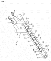
- Fig. 1 shows an embodiment of the present invention, plasma emitting device 10.
- Plasma emitting device 10 is for medical use and is for applying plasma to an affected body part.
- Plasma emitting device 10 is provided with plasma ejecting device 12, laser emitting device 14, inert gas ejecting device 16, and control device 18 (refer to fig. 5 ).
- Plasma ejecting device 12 is for ejecting plasma and is provided with main body 20, light receiving element 21, pair of electrodes 22 and 24, glass tube 26, and processing gas supply device 28.
- Main body section 20 is formed from sapphire glass and is configured from cylindrical section 30, bent section 32, and dividing section 34.
- Cylindrical section 30 is substantially a round tube.
- Bent section 32 is a tube bent into an L-shape, and an end section thereof is connected in an upright state to an outer surface of cylindrical section 30 near an end of cylindrical section 30.
- the inside of cylindrical section 30 and the inside of bent section 32 are linked.
- Dividing section 34 is a short cylinder and is connected in an upright state to cylindrical section 30 on the opposite side to bent section 32.
- the inside of cylindrical section 30 and the inside of dividing section 34 are linked.
- Light receiving element 21 is arranged on the lower end of dividing section 34. Light receiving element 21, to be described in detail later, functions as a light receiving sensor, and a distance between a processing target and plasma emitting
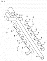
- Electrode 22 includes multiple electrical discharge sections 50 and multiple connecting sections 56
- electrode 24 includes multiple electrical discharge sections 52 and multiple connecting sections 58. Note that, fig. 2 is a theoretical view showing electrodes 22 and 24 removed from cylindrical section 30.
- the multiple electrical discharge sections 50 of electrode 22 are vacuum deposited on the outer circumferential surface of cylindrical section 30 extending in the circumferential direction, and are arranged at a specified interval lined up in the axis direction of cylindrical section 30.
- connecting sections 56 of electrode 22 are vacuum deposited on the outer circumferential surface of cylindrical section 30 extending in a line in the axis direction of cylindrical section 30, and are connected to the multiple electrical discharge sections 50.
- electrical discharge section 50 positioned at one end is vacuum deposited around the entire circumference in the circumferential direction of cylindrical section 30; the other electrical discharge sections 50 are vacuum deposited extending in the circumferential direction of cylindrical section 30, except for a portion on the opposite side to connecting section 56.
- Current passing section 60 is formed on the electrical discharge section 50 vacuum deposited across the entire circumference in the circumferential direction of cylindrical section 30 protruding from an end of cylindrical section 30.
- the multiple electrical discharge sections 52 of electrode 24 are vacuum deposited on the outer circumferential surface of cylindrical section 30 extending in the circumferential direction, and are arranged lined up in the axis direction of cylindrical section 30 so as to be positioned between the multiple electrical discharge sections 50 of electrode 22. Note that, from among the multiple electrical discharge sections 52 of electrode 24, electrical discharge sections 52 positioned between two of the electrical discharge sections 50 of electrode 22 are vacuum deposited extending in the circumferential direction of cylindrical section 30 excluding connecting section 56 of electrode 22; the remaining electrical discharge sections 52 positioned at the ends are vacuum deposited across the entire circumference in the circumferential direction of cylindrical section 30.
- Current passing section 62 is formed on the electrical discharge section 52 vacuum deposited across the entire circumference in the circumferential direction of cylindrical section 30 protruding from an end of cylindrical section 30.
- connecting sections 58 of electrode 24 are vacuum deposited on the outer circumferential surface of cylindrical section 30 extending in a line in the axis direction of cylindrical section 30 at locations where electrical discharge sections 50 of electrode 22 are not vacuum deposited, and are connected to the multiple electrical discharge sections 52.
- the pair of electrodes 22 and 24 have electrical discharge sections 50 of electrode 22 and electrical discharge sections 52 of electrode 24 vacuum deposited on the outer circumferential surface of cylindrical section 30 lined up alternately with a specified gap between them.
- glass tube 26 is arranged on the outer circumferential surface of cylindrical section 30 of main body 20 so as to entirely cover the pair of electrodes 22 and 24 vacuum deposited on the outer circumferential surface of cylindrical section 30.
- glass tube 26 encroaches in between electrical discharge sections 50 of electrode 22 and electrical discharge sections 52 of electrode 24.
- Gas supply device 28 supplies processing gas and is connected to an end of bent section 32 opposite to an end of bent section 32 that is connected to cylindrical section 30.
- processing gas is supplied inside cylindrical section 30 via bent section 32.
- processing gas may be gas in which an inert gas such as nitrogen or argon is mixed with active gases in the air such as oxygen at a given ratio, or may be only an inert gas, or only an active gas.
- processing gas supply device 28 may also be provided with a function to heat or cool the processing gas, such that processing gas can be supplied at a given temperature.
- Laser emitting device 14 emits laser light and is substantially a short cylinder. An end surface of laser emitting device 14 is coaxially connected to an end surface of cylindrical section 30 at which bent section 32 is arranged. In a central portion of the end surface of laser emitting device 14 connected to cylindrical section 30, emitting hole 67 (refer to fig. 2 ) is formed, and laser emitting device 14 emits laser light from emitting hole 67 in an axial direction of cylindrical section 30.
- laser light is monochromatic and has directionality and coherence.
- Directionality means that emitted light travels substantially straight without being spread.
- Being monochromatic means that the wavelength of the light is narrow, that is, of a single color.
- Coherence is related to a fixed relationship between the amplitude and phase of two or more waves of light, wherein interference fringes occur when the two or more waves of light interfere. Laser light with such qualities converges in a narrow range.
- laser light emitted from laser emitting device 14 is red light with a visible wavelength.
- laser light emitted from laser emitting device 14 passes through the inside of cylindrical section 30, and is emitted towards the outside of plasma emitting device 10 from the end of cylindrical section 30 opposite to the end at which laser emitting device 14 is provided (also referred to as the "front end" of cylindrical section 30).
- processing target 68 is positioned opposite the front end of cylindrical section 30
- laser light emitted by laser emitting device 14 is applied to processing target 68.
- Reflector 69 is arranged inside cylindrical section 30 opposite to dividing section 34. Reflector 69 is arranged at a 45 degree angle with respect to the axis direction of cylindrical section 30, and the reflective surface faces towards dividing section 34. Note that, the reflectance of reflector 69 is 50%, and the permeability is 50%. Therefore, 50% of the laser light emitted from laser emitting device 14 passes through reflector 69 and is emitted outside of plasma emitting device 10. Therefore, 50% of the laser light emitted from laser emitting device 14 is applied to processing target 68. Light applied to processing target 68 is reflected by processing target 68, and that reflected light is reflected inside cylindrical section 30 coaxially to the laser light emitted from laser light emitting device 14.
- the reflected light that goes through the inside of cylindrical section 30 is reflected by reflector 69 and goes through the inside of dividing section 34.
- the reflected light is then detected by light receiving element 21 and the distance between plasma emitting device 10 and processing target 68 is calculated based on the detected light. Details about calculation of the distance between plasma emitting device 10 and processing target 68 are described later.
- Inert gas ejecting device 16 is for ejecting an inert gas such as nitrogen, argon, or helium, and is arranged to cover cylindrical section 30 of plasma ejecting device 12.
- Inert gas ejecting device 16 is provided with main body 70, inert gas supply device 72, and cooling device 74.
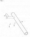
- main body 70 is configured from cylindrical section 76 and bent section 78.
- Cylindrical section 76 is substantially a round tube with an inside diameter larger than the outside diameter of cylindrical tube 30 of plasma ejecting device 12.
- Cylindrical section 30 of plasma ejecting device 12 is inserted inside cylindrical section 76 with a clearance gap between the outside surface of cylindrical section 30 and the inside surface of cylindrical section 76.
- Cylindrical section 76 is shorter than cylindrical section 30 of plasma ejecting device 12. Also, as shown in fig. 1 , the end surface of the front end of cylindrical section 30 of plasma ejecting device 12 is aligned with the end surface of cylindrical section 76. The other end of cylindrical section 76 is positioned towards bent section 32 and dividing section 34 of plasma ejecting device 12 and is blocked up.
- Bent section 78 is a tube bent into an L-shape, and an end section thereof is connected in an upright state to an outer surface of cylindrical section 76 near the end of cylindrical section 76 towards bent section 32 and dividing section 34.
- the inside of cylindrical section 76 and the inside of bent section 78 are linked.
- Inert gas supply device 72 is connected, via cooling device 74, to the end of bent section 78 opposite to the end of bent section 78 connected to cylindrical section 76.
- Inert gas supply device 72 supplies inert gas
- cooling device 74 cools inert gas supplied by inert gas supply device 72.
- cooled inert gas is supplied inside cylindrical section 76 via bent section 78.
- control device 18 is provided with controller 80, multiple drive circuits 82, and control circuit 86.
- the multiple drive circuits 82 are connected to electrodes 22 and 24, processing gas supply device 28, laser emitting device 14, inert gas supply device 72, and cooling device 74.
- Controller 80 is provided with a CPU, ROM, RAM, and so on, is formed mainly from a computer, and is connected to the multiple drive circuits 82. By this, operation of plasma emitting device 10 is controlled by controller 80.
- Controller 80 is also connected to light receiving element 21. Controller 80 acquires information related to light received by light receiving element 21.
- Controller 80 is also connected to display lamp 88 via control circuit 86.
- Display lamp 88 is a lamp that displays a red or green light and controller 80 causes display lamp 88 to shine red or green.
- Plasma is ejected from the front end of cylindrical section 30 of plasma ejecting device 12 to be applied to processing target 68.
- Plasma includes active radicals and is used in medical fields for the purpose of treating an affected body part with active radicals.
- oxygen plasma is applied to processing target 68.
- Oxygen plasma is effective at killing cells, and, for example, by applying the oxygen plasma to cancerous cells, can be used for the purpose of cancer treatment.
- hydrogen plasma can be applied to processing target 68.
- Hydrogen plasma is effective for regenerating cells, and, for example, by applying the hydrogen plasma to skin, can be used for the purpose of skin regeneration treatment.
- processing gas is supplied by processing gas supply device 28 inside cylindrical section 30 via bent section 32. Because the end of cylindrical section 30 at which bent section 32 is arranged is covered by laser emitting device 14, processing gas supplied to cylindrical section 30 flows from that end towards the opposite end. That is, processing gas flows towards the inside of cylindrical section 30 on which electrodes 22 and 24 are vacuum deposited.
- Electrodes 22 and 24 are encased by glass tube 26, which is an insulating body, electrical discharge is generated inside cylindrical section 30 such that the processing gas flowing inside cylindrical section 30 is plasmarized.
- plasma is emitted in an axial direction of cylindrical section 30 from an opening (also referred to as a "plasma emission port") of cylindrical section 30 formed in an end surface of cylindrical section 30 opposite to an end of cylindrical section 30 to which laser emitting device 14 is connected.
- a person giving treatment such as a doctor, points the plasma emission port towards the affected body part of the patient to treat the affected body part by applying plasma.
- the concentration of active radicals in the applied plasma should be appropriate in order to perform appropriate treatment, therefore the concentration of processing gas supplied from processing gas supply device 28 is appropriately controlled.
- active radicals will deactivate, and the concentration of plasma active radicals applied to the affected body part may no longer be appropriate for treatment In such a case, appropriate treatment cannot be guaranteed. Also, the effectiveness of treatment is lowered by the deactivation of the plasma.
- inert gas is ejected together with the plasma.
- inert gas is supplied from inert gas supply device 72 to bent section 78 via cooling device 74.
- inert gas supplied from inert gas supply device 72 is cooled by cooling device 74.
- cooled inert gas is supplied inside cylindrical section 76 via bent section 78.
- processing gas supplied to cylindrical section 76 flows from that end towards the opposite end.
- the inert gas flows between the inner surface of cylindrical section 76 and the outer surface of cylindrical section 30.
- inert gas is ejected from the opening (also referred to as "inert gas emission port") of cylindrical section 76 at the end of cylindrical section 76 opposite to the end at which bent section 78 is arranged.
- inert gas ejected from the inert gas emission port has a cylindrical shape.
- Plasma is ejected through the inside of the inert gas ejected in a cylindrical shape. That is, the inert gas is ejected so as to cover the outer circumference of the ejected plasma.
- the ejected plasma is shielded by the inert gas such that the plasma can be applied to the affected body part without being exposed to air.
- an appropriate concentration of plasma can be applied to the affected body part thereby enabling effective treatment.
- effective treatment is enabled by preventing deactivation of the plasma.
- plasma is ejected from the plasma emission port after inert gas is ejected from the the inert gas emission port. That is, first inert gas is supplied from inert gas supply device 72 such that inert gas is ejected from the inert gas emission port. Then, after the inert gas has started to be ejected from the inert gas emission port, processing gas is supplied from processing gas supply device 28 and voltage is applied to the pair of electrodes 22 and 24. Therefore, inert gas is ejected in a cylindrical shape to cover the plasma emission port before plasma starts to be ejected from the plasma emission port, and the plasma is then ejected inside the cylindrical inert gas. Thus, plasma ejected from the plasma emission port is reliably blocked from contacting the air.
- the ejection speed of the inert gas ejected from the inert gas emission port is faster than the ejection speed of the plasma ejected from the plasma emission port such that spreading of the inert gas is prevented.
- a gas referred to as a "first gas”
- a gas referred to as a "second gas”
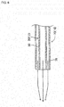
- inert gas (second gas) ejected from the inert gas emission port flows towards the plasma (first gas) ejected from the plasma emission port (inside of cylindrical section 30).
- the inert gas converges on the plasma, preventing the inert gas from spreading. This prevents the shield around the plasma being broken due to spreading of the inert gas.
- the ejection speed of the plasma and the ejection speed of the inert gas are adjusted by adjusting the amount of gas supplied by processing gas supply device 28 and inert gas supply device 72.
- plasma ejected from the plasma ejection port has a tendency to become hot due to the high voltage electrical discharge, but the inert gas shielding the ejected plasma is cooled gas. Therefore, the temperature of the plasma ejected from the plasma emission port is lowered, preventing hot plasma being applied to the affected body part.
- plasma emitting device 10 is provided with laser emitting device 14, and by the laser light emitted by laser emitting device 14, the application position of the plasma can be checked.
- laser emitting device 14 is connected to an end surface of cylindrical section 30 of plasma ejecting device 12, and emits laser light in an axial direction of cylindrical section 30. That is, laser emitting device 14 emits laser light coaxially with the emission direction of plasma. Also, laser light is directional light that travels straight. Thus, the laser light emitted from laser emitting device 14 passes through cylindrical section 30 and is emitted from the plasma emission port of cylindrical section 30 coaxially to the ejection direction of the plasma. By this, as shown in fig. 3 , laser light is applied to a location to which the plasma is applied. Because the laser light is red laser light of a high frequency in a visible range, the person providing treatment is able to appropriately apply plasma to the processing target 68 while visually checking the laser light.
- the processing target 68 to which plasma is to be applied is too far away from plasma emitting device 10, the plasma may not reach the processing target 68, thereby lowering the effectiveness of the plasma treatment.
- plasma emitting device 10 is provided with light receiving element 21 and, as shown in fig. 3 , laser light emitted towards processing target 68 from laser emitting device 14 is reflected and the reflected light is received by light receiving element 21.
- AM amplitude modulation
- AM amplitude modulation
- the amplitude of amplitude modulated laser light changes over time. Therefore, a phase difference arises between a wave of laser light emitted from laser emitting device 14 and a wave of laser light received by laser receiving element 21, with that phase difference being calculated by controller 80.
- the phase difference is proportional to the travel distance of the light received by light receiving element 21 that was emitted from laser emitting device 14 towards processing target 68 and reflected by processing target 68, that is, is proportional to the emission distance of the laser light (also referred to as "laser emission distance").
- the distance between laser emitting device 14 and reflector 69 is the same as the distance between reflector 69 and light receiving element 21. Therefore, the laser emission distance is 2 x L 0 , and controller 80 calculates the laser emission distance (2 x L 0 ) based on the phase difference. Length L 2 of cylindrical section 30 is memorized in controller 80. Therefore, by subtracting the length of cylindrical section 30 (L 2 ) from half of the laser emission distance (2 x L 0 ), distance L 1 between the plasma emission port of cylindrical section 30 and processing target 68, that is, the processing target separation distance, can be calculated.
- controller 80 After the processing target separation distance is calculated, it is determined whether the processing target separation distance is within a predetermined set range. If the calculated processing target separation distance is within the set range, controller 80 causes display lamp 88 to display a green light; if the calculated processing target separation distance is not within the set range, controller 80 causes display lamp 88 to display a red light.
- the set range can be entered by an operator via an input device (not shown) and can be set to any range. Therefore, by entering an appropriate range for plasma treatment as the set range, an operator can guarantee appropriate plasma treatment. That is, a person giving treatment can move plasma emitting device 10 towards the affected body part, that is, processing target 68, while applying plasma to the processing target 68 such that a green light is always displayed by display lamp 88, thereby guaranteeing appropriate plasma treatment.
- the processing target separation distance can be calculated using the laser light used for checking the plasma application position, and whether the processing target separation distance is appropriate can be reported to the person performing treatment
- the person performing treatment can perform treatment while checking the plasma application position and the plasma emission distance, thereby guaranteeing appropriate plasma treatment.
- the laser light used for checking the plasma application position, costs are greatly reduced. Also, as described above, the laser light is emitted coaxially with the emission axis of the plasma, and the processing target separation distance is calculated based on the laser light emission distance. Therefore, the calculated processing target separation distance matches the plasma emission distance, so the plasma emission distance can be calculated accurately.
- controller 80 of control device 18 includes calculating section 100 and display control section 102.
- Calculating section 100 is for calculating the processing target separation distance.
- Display control section 102 is for causing display lamp 88 to display a light based on the calculated processing target separation distance, and acts as the functional section for reporting the processing target separation distance to the person performing treatment
- plasma emitting device 10 is an example of a medical-use plasma generating device.
- Plasma ejecting device 12 is an example of a plasma ejecting device.
- Laser emitting device 14 is an example of a laser emitting device.
- Inert gas ejecting device 16 is an example of an inert gas ejecting device.
- Light receiving element 21 is an example of a light receiving element.
- Cylindrical section 30 is an example of an inner housing.
- Cooling device 74 is an example of a cooling device.
- Cylindrical section 76 is an example of an outer housing.
- Calculating section 100 is an example of a calculating device.
- the present invention is not limited to the above example embodiments, and various changed or improved methods of embodiment are possible based on the knowledge of someone skilled in the art. Specifically, for example, in an embodiment above, whether the calculated processing target separation distance is within a set range is reported to a person performing treatment using display lamp 88, but this may be reported by displaying the value of the calculated processing target separation distance, or by outputting audio of the value of the calculated processing target separation distance.
- the processing target separation distance is calculated using the phase difference between laser light emitted by laser emitting device 14 and laser light received by light receiving element 21, but the processing target separation distance may be calculated using the time lag between the emission timing of the laser light by laser emitting device 14 and the receiving timing of the laser light by light receiving element 21.
- laser emitting device 14 may emit laser light with a predetermined pulse width and the emission time may be memorized.
- the receiving time at which light receiving element 21 receives the reflected light may be memorized.
- the difference between the emission time and the receiving time may be calculated as time lag ⁇ t
- processing target separation distance L 1 can be calculated in a similar manner to that described above.
- laser light is used as light applied to processing target 68, but various types of light may be used, so long as the light is visible.
- it is desirable to appropriately calculate the processing target separation distance using reflected light thus it is desirable to use light with excellent straightness and convergence properties, that is, so-called directional light.
Landscapes
- Health & Medical Sciences (AREA)
- Engineering & Computer Science (AREA)
- Life Sciences & Earth Sciences (AREA)
- Physics & Mathematics (AREA)
- Biomedical Technology (AREA)
- Plasma & Fusion (AREA)
- General Health & Medical Sciences (AREA)
- Nuclear Medicine, Radiotherapy & Molecular Imaging (AREA)
- Animal Behavior & Ethology (AREA)
- Veterinary Medicine (AREA)
- Public Health (AREA)
- Surgery (AREA)
- Pathology (AREA)
- Radiology & Medical Imaging (AREA)
- Molecular Biology (AREA)
- Medical Informatics (AREA)
- Heart & Thoracic Surgery (AREA)
- Spectroscopy & Molecular Physics (AREA)
- Otolaryngology (AREA)
- Fluid Mechanics (AREA)
- Biophysics (AREA)
- Oral & Maxillofacial Surgery (AREA)
- Electromagnetism (AREA)
- Plasma Technology (AREA)
- Surgical Instruments (AREA)
Abstract
Description
- The present invention relates to a medical-use plasma generating device and a plasma emitting method using the medical-use plasma generating device for use in plasma medical treatments.
- Plasma processing is performed by a plasma generating device ejecting plasma from an emission port towards a processing target such that plasma is applied to the processing target. Examples of a plasma generating device is disclosed in the patent literature below.
- Patent literature 1:
WO2013/0108797 - Patent literature 2:
JP-A-2012-059548 - Plasma includes active radicals and research is progressing of emitting plasma for medical treatment purposes, wherein the surface of a processing body is activated by plasma being applied. Specifically, for example, oxygen plasma generated by using oxygen as a processing gas is effective for killing cells, and by applying oxygen plasma to cancerous cells, emitting of such plasma can be used for the purpose of cancer treatment. Also, for example, hydrogen plasma generated by using hydrogen as a processing gas is effective for regenerating cells, and by applying hydrogen plasma to skin, emitting of such plasma can be used for the purpose of skin regeneration treatment. In such ways, emitting of plasma is performed for medical treatment purposes, but for medical treatment, the concentration of the processing gas and so on is controlled strictly. However, because active radicals in plasma are unstable, there is a tendency for the effectiveness of the plasma to be lowered when the plasma is being applied to the processing target. Also, because plasma is invisible, it is difficult to apply plasma to the processing target appropriately. Thus, there remains considerable room for improvement of a medical-use plasma generating device, and the practicality of a medical-use plasma generating device may be improved by applying various refinements. The present invention takes account of such problems, and an object thereof is to provide a medical-use plasma generating device with high practicality.
- To solve the above problems, a medical-use plasma generating device of the present disclosure includes: a plasma ejecting device configured to eject plasma; and an inert gas ejecting device configured to eject an inert gas such that an outer circumference of the plasma ejected by the plasma ejecting device is covered by the inert gas.
- To solve the above problems, a plasma emitting method of the present disclosure is a plasma emitting method for applying plasma to a processing target using a medical-use plasma generating device provided with a plasma ejecting device configured to eject plasma, and an inert gas ejecting device configured to eject an inert gas such that an outer circumference of the plasma ejected by the plasma emitting device is covered by the inert gas, the plasma emitting method including: ejecting an inert gas using the inert gas ejecting device; and after ejecting the inert gas, ejecting plasma using the plasma ejecting device.
- With an atmospheric pressure plasma generating device of the present disclosure, inert gas is ejected to surround an outer circumference of ejected plasma. Thus, the ejected plasma is shielded by the inert gas such that the plasma can be applied to a processing target, that is, an affected body part, without being exposed to air. Accordingly, deactivation of the plasma by air is prevented, and plasma medical treatment can be performed without decreasing the effect that is expected based on a strictly managed concentration of the processing gas.
- Also, with a plasma emitting method of the present disclosure, plasma is ejected after the inert gas is ejected. Thus, before plasma is ejected, inert gas is ejected to cover the plasma emission port, meaning that the plasma is ejected through the inert gas. This means it is possible to reliably block air from contacting plasma ejected from the emission port.
-
-
Fig. 1 is a perspective view of a plasma emitting device. -
Fig. 2 is an exploded view of a plasma ejecting device. -
Fig. 3 is a cross section view of the plasma emitting device. -
Fig. 4 is a perspective view of an inert gas ejecting device. -
Fig. 5 is a block diagram showing a control device. -
Fig. 6 illustrates the flow of plasma and inert gas. - The following describes in detail referring to the figures an example embodiment of the present invention.
-
Fig. 1 shows an embodiment of the present invention,plasma emitting device 10.Plasma emitting device 10 is for medical use and is for applying plasma to an affected body part.Plasma emitting device 10 is provided withplasma ejecting device 12,laser emitting device 14, inertgas ejecting device 16, and control device 18 (refer tofig. 5 ). -
Plasma ejecting device 12 is for ejecting plasma and is provided withmain body 20,light receiving element 21, pair ofelectrodes glass tube 26, and processinggas supply device 28.Main body section 20 is formed from sapphire glass and is configured fromcylindrical section 30,bent section 32, and dividingsection 34.Cylindrical section 30 is substantially a round tube.Bent section 32 is a tube bent into an L-shape, and an end section thereof is connected in an upright state to an outer surface ofcylindrical section 30 near an end ofcylindrical section 30. The inside ofcylindrical section 30 and the inside ofbent section 32 are linked. Dividingsection 34 is a short cylinder and is connected in an upright state tocylindrical section 30 on the opposite side tobent section 32. The inside ofcylindrical section 30 and the inside of dividingsection 34 are linked.Light receiving element 21 is arranged on the lower end of dividingsection 34.Light receiving element 21, to be described in detail later, functions as a light receiving sensor, and a distance between a processing target andplasma emitting device 10 is calculated based on the received light. - Multiple
electrical discharge sections electrodes cylindrical section 30 ofmain body 20 so as to be lined up alternately in an axis direction ofcylindrical section 30. In detail, as shown infig. 2 ,electrode 22 includes multipleelectrical discharge sections 50 and multiple connectingsections 56, andelectrode 24 includes multipleelectrical discharge sections 52 and multiple connectingsections 58. Note that,fig. 2 is a theoreticalview showing electrodes cylindrical section 30. - The multiple
electrical discharge sections 50 ofelectrode 22 are vacuum deposited on the outer circumferential surface ofcylindrical section 30 extending in the circumferential direction, and are arranged at a specified interval lined up in the axis direction ofcylindrical section 30. Also, connectingsections 56 ofelectrode 22 are vacuum deposited on the outer circumferential surface ofcylindrical section 30 extending in a line in the axis direction ofcylindrical section 30, and are connected to the multipleelectrical discharge sections 50. Note that, from among the multipleelectrical discharge sections 50 ofelectrode 22,electrical discharge section 50 positioned at one end is vacuum deposited around the entire circumference in the circumferential direction ofcylindrical section 30; the otherelectrical discharge sections 50 are vacuum deposited extending in the circumferential direction ofcylindrical section 30, except for a portion on the opposite side to connectingsection 56.Current passing section 60 is formed on theelectrical discharge section 50 vacuum deposited across the entire circumference in the circumferential direction ofcylindrical section 30 protruding from an end ofcylindrical section 30. - Further, the multiple
electrical discharge sections 52 ofelectrode 24 are vacuum deposited on the outer circumferential surface ofcylindrical section 30 extending in the circumferential direction, and are arranged lined up in the axis direction ofcylindrical section 30 so as to be positioned between the multipleelectrical discharge sections 50 ofelectrode 22. Note that, from among the multipleelectrical discharge sections 52 ofelectrode 24,electrical discharge sections 52 positioned between two of theelectrical discharge sections 50 ofelectrode 22 are vacuum deposited extending in the circumferential direction ofcylindrical section 30 excluding connectingsection 56 ofelectrode 22; the remainingelectrical discharge sections 52 positioned at the ends are vacuum deposited across the entire circumference in the circumferential direction ofcylindrical section 30.Current passing section 62 is formed on theelectrical discharge section 52 vacuum deposited across the entire circumference in the circumferential direction ofcylindrical section 30 protruding from an end ofcylindrical section 30. Also, connectingsections 58 ofelectrode 24 are vacuum deposited on the outer circumferential surface ofcylindrical section 30 extending in a line in the axis direction ofcylindrical section 30 at locations whereelectrical discharge sections 50 ofelectrode 22 are not vacuum deposited, and are connected to the multipleelectrical discharge sections 52. Thus, the pair ofelectrodes electrical discharge sections 50 ofelectrode 22 andelectrical discharge sections 52 ofelectrode 24 vacuum deposited on the outer circumferential surface ofcylindrical section 30 lined up alternately with a specified gap between them. - As shown in
fig. 1 ,glass tube 26 is arranged on the outer circumferential surface ofcylindrical section 30 ofmain body 20 so as to entirely cover the pair ofelectrodes cylindrical section 30. By this, it is possible to prevent exposure ofelectrodes electrodes glass tube 26,glass tube 26 encroaches in betweenelectrical discharge sections 50 ofelectrode 22 andelectrical discharge sections 52 ofelectrode 24. -
Gas supply device 28 supplies processing gas and is connected to an end ofbent section 32 opposite to an end ofbent section 32 that is connected tocylindrical section 30. Thus, processing gas is supplied insidecylindrical section 30 viabent section 32. Note that, processing gas may be gas in which an inert gas such as nitrogen or argon is mixed with active gases in the air such as oxygen at a given ratio, or may be only an inert gas, or only an active gas. Also, processinggas supply device 28 may also be provided with a function to heat or cool the processing gas, such that processing gas can be supplied at a given temperature. -
Laser emitting device 14 emits laser light and is substantially a short cylinder. An end surface oflaser emitting device 14 is coaxially connected to an end surface ofcylindrical section 30 at whichbent section 32 is arranged. In a central portion of the end surface oflaser emitting device 14 connected tocylindrical section 30, emitting hole 67 (refer tofig. 2 ) is formed, andlaser emitting device 14 emits laser light from emittinghole 67 in an axial direction ofcylindrical section 30. - Note that, laser light is monochromatic and has directionality and coherence. Directionality means that emitted light travels substantially straight without being spread. Being monochromatic means that the wavelength of the light is narrow, that is, of a single color. Coherence is related to a fixed relationship between the amplitude and phase of two or more waves of light, wherein interference fringes occur when the two or more waves of light interfere. Laser light with such qualities converges in a narrow range. Note that, laser light emitted from
laser emitting device 14 is red light with a visible wavelength. - By arranging
laser emitting device 14 at an end ofcylindrical section 30 ofplasma emitting device 12 in this manner, as shown infig. 3 , laser light emitted fromlaser emitting device 14 passes through the inside ofcylindrical section 30, and is emitted towards the outside ofplasma emitting device 10 from the end ofcylindrical section 30 opposite to the end at whichlaser emitting device 14 is provided (also referred to as the "front end" of cylindrical section 30). Thus, in a case in whichprocessing target 68 is positioned opposite the front end ofcylindrical section 30, laser light emitted bylaser emitting device 14 is applied to processingtarget 68. -
Reflector 69 is arranged insidecylindrical section 30 opposite to dividingsection 34.Reflector 69 is arranged at a 45 degree angle with respect to the axis direction ofcylindrical section 30, and the reflective surface faces towards dividingsection 34. Note that, the reflectance ofreflector 69 is 50%, and the permeability is 50%. Therefore, 50% of the laser light emitted fromlaser emitting device 14 passes throughreflector 69 and is emitted outside ofplasma emitting device 10. Therefore, 50% of the laser light emitted fromlaser emitting device 14 is applied to processingtarget 68. Light applied to processingtarget 68 is reflected by processingtarget 68, and that reflected light is reflected insidecylindrical section 30 coaxially to the laser light emitted from laserlight emitting device 14. The reflected light that goes through the inside ofcylindrical section 30 is reflected byreflector 69 and goes through the inside of dividingsection 34. The reflected light is then detected by light receivingelement 21 and the distance betweenplasma emitting device 10 andprocessing target 68 is calculated based on the detected light. Details about calculation of the distance betweenplasma emitting device 10 andprocessing target 68 are described later. - Inert
gas ejecting device 16 is for ejecting an inert gas such as nitrogen, argon, or helium, and is arranged to covercylindrical section 30 ofplasma ejecting device 12. Inertgas ejecting device 16 is provided withmain body 70, inertgas supply device 72, and coolingdevice 74. As shown infig. 4 ,main body 70 is configured fromcylindrical section 76 andbent section 78.Cylindrical section 76 is substantially a round tube with an inside diameter larger than the outside diameter ofcylindrical tube 30 ofplasma ejecting device 12.Cylindrical section 30 ofplasma ejecting device 12 is inserted insidecylindrical section 76 with a clearance gap between the outside surface ofcylindrical section 30 and the inside surface ofcylindrical section 76. -
Cylindrical section 76 is shorter thancylindrical section 30 ofplasma ejecting device 12. Also, as shown infig. 1 , the end surface of the front end ofcylindrical section 30 ofplasma ejecting device 12 is aligned with the end surface ofcylindrical section 76. The other end ofcylindrical section 76 is positioned towardsbent section 32 and dividingsection 34 ofplasma ejecting device 12 and is blocked up. -
Bent section 78 is a tube bent into an L-shape, and an end section thereof is connected in an upright state to an outer surface ofcylindrical section 76 near the end ofcylindrical section 76 towardsbent section 32 and dividingsection 34. The inside ofcylindrical section 76 and the inside ofbent section 78 are linked. - Inert
gas supply device 72 is connected, via coolingdevice 74, to the end ofbent section 78 opposite to the end ofbent section 78 connected tocylindrical section 76. Inertgas supply device 72 supplies inert gas, and coolingdevice 74 cools inert gas supplied by inertgas supply device 72. Thus, cooled inert gas is supplied insidecylindrical section 76 viabent section 78. - As shown in
fig. 5 ,control device 18 is provided withcontroller 80,multiple drive circuits 82, andcontrol circuit 86. Themultiple drive circuits 82 are connected toelectrodes gas supply device 28,laser emitting device 14, inertgas supply device 72, and coolingdevice 74.Controller 80 is provided with a CPU, ROM, RAM, and so on, is formed mainly from a computer, and is connected to themultiple drive circuits 82. By this, operation ofplasma emitting device 10 is controlled bycontroller 80.Controller 80 is also connected to light receivingelement 21.Controller 80 acquires information related to light received by light receivingelement 21.Controller 80 is also connected to displaylamp 88 viacontrol circuit 86.Display lamp 88 is a lamp that displays a red or green light andcontroller 80 causes displaylamp 88 to shine red or green. - According to the above configuration, with
plasma emitting device 10, plasma is ejected from the front end ofcylindrical section 30 ofplasma ejecting device 12 to be applied to processingtarget 68. Plasma includes active radicals and is used in medical fields for the purpose of treating an affected body part with active radicals. Specifically, for example, by using oxygen as a processing gas, oxygen plasma is applied to processingtarget 68. Oxygen plasma is effective at killing cells, and, for example, by applying the oxygen plasma to cancerous cells, can be used for the purpose of cancer treatment. Also, for example, by using hydrogen as a processing gas, hydrogen plasma can be applied to processingtarget 68. Hydrogen plasma is effective for regenerating cells, and, for example, by applying the hydrogen plasma to skin, can be used for the purpose of skin regeneration treatment. - Specifically, in
plasma emitting device 10, processing gas is supplied by processinggas supply device 28 insidecylindrical section 30 viabent section 32. Because the end ofcylindrical section 30 at whichbent section 32 is arranged is covered bylaser emitting device 14, processing gas supplied tocylindrical section 30 flows from that end towards the opposite end. That is, processing gas flows towards the inside ofcylindrical section 30 on whichelectrodes - Voltage is applied to current passing
sections electrodes electrodes electrical discharge sections electrodes electrodes glass tube 26, which is an insulating body, electrical discharge is generated insidecylindrical section 30 such that the processing gas flowing insidecylindrical section 30 is plasmarized. Thus, plasma is emitted in an axial direction ofcylindrical section 30 from an opening (also referred to as a "plasma emission port") ofcylindrical section 30 formed in an end surface ofcylindrical section 30 opposite to an end ofcylindrical section 30 to whichlaser emitting device 14 is connected. Here, a person giving treatment, such as a doctor, points the plasma emission port towards the affected body part of the patient to treat the affected body part by applying plasma. - Note that, when plasma is applied to the affected body part, the concentration of active radicals in the applied plasma should be appropriate in order to perform appropriate treatment, therefore the concentration of processing gas supplied from processing
gas supply device 28 is appropriately controlled. However, if air contacts the plasma from when the plasma is ejected from the plasma emission port ofplasma emitting device 10 to when the plasma is applied to the affected body part, active radicals will deactivate, and the concentration of plasma active radicals applied to the affected body part may no longer be appropriate for treatment In such a case, appropriate treatment cannot be guaranteed. Also, the effectiveness of treatment is lowered by the deactivation of the plasma. - Considering this, with
plasma emitting device 10, when applying plasma to an affected body part, inert gas is ejected together with the plasma. In detail, inert gas is supplied from inertgas supply device 72 tobent section 78 viacooling device 74. Here, inert gas supplied from inertgas supply device 72 is cooled by coolingdevice 74. Thus, cooled inert gas is supplied insidecylindrical section 76 viabent section 78. Because the end ofcylindrical section 76 at whichbent section 78 is arranged is blocked up, processing gas supplied tocylindrical section 76 flows from that end towards the opposite end. Here, the inert gas flows between the inner surface ofcylindrical section 76 and the outer surface ofcylindrical section 30. Also, inert gas is ejected from the opening (also referred to as "inert gas emission port") ofcylindrical section 76 at the end ofcylindrical section 76 opposite to the end at whichbent section 78 is arranged. - Because inert gas is ejected between the inner circumferential surface of
cylindrical section 76 and the outer circumferential surface ofcylindrical section 30, inert gas ejected from the inert gas emission port has a cylindrical shape. Plasma is ejected through the inside of the inert gas ejected in a cylindrical shape. That is, the inert gas is ejected so as to cover the outer circumference of the ejected plasma. Thus, the ejected plasma is shielded by the inert gas such that the plasma can be applied to the affected body part without being exposed to air. Thus, an appropriate concentration of plasma can be applied to the affected body part thereby enabling effective treatment. Also, effective treatment is enabled by preventing deactivation of the plasma. - Because it is desirable to reliably block the plasma from contacting the air, plasma is ejected from the plasma emission port after inert gas is ejected from the the inert gas emission port. That is, first inert gas is supplied from inert
gas supply device 72 such that inert gas is ejected from the inert gas emission port. Then, after the inert gas has started to be ejected from the inert gas emission port, processing gas is supplied from processinggas supply device 28 and voltage is applied to the pair ofelectrodes - Further, the ejection speed of the inert gas ejected from the inert gas emission port is faster than the ejection speed of the plasma ejected from the plasma emission port such that spreading of the inert gas is prevented. In detail, if a gas (referred to as a "first gas") flowing at a given speed and a gas (referred to as a "second gas") flowing a speed faster than the given speed are flowing in the same direction, friction arises between the first gas and the second gas, and the second gas flows towards the first gas. Therefore, by making the ejection speed of the inert gas faster than the ejection speed of the plasma, as shown in
fig. 6 , inert gas (second gas) ejected from the inert gas emission port (between the inner circumferential surface ofmain body 70 and the inner circumferential surface of cylindrical section 30) flows towards the plasma (first gas) ejected from the plasma emission port (inside of cylindrical section 30). Thus, the inert gas converges on the plasma, preventing the inert gas from spreading. This prevents the shield around the plasma being broken due to spreading of the inert gas. Note that, the ejection speed of the plasma and the ejection speed of the inert gas are adjusted by adjusting the amount of gas supplied by processinggas supply device 28 and inertgas supply device 72. - Also, plasma ejected from the plasma ejection port has a tendency to become hot due to the high voltage electrical discharge, but the inert gas shielding the ejected plasma is cooled gas. Therefore, the temperature of the plasma ejected from the plasma emission port is lowered, preventing hot plasma being applied to the affected body part.
- Note that, because the wavelength of the plasma is in a vacuum ultraviolet range, it cannot be checked visually. Therefore, the plasma may not be applied to the affected body part appropriately. Considering this,
plasma emitting device 10 is provided withlaser emitting device 14, and by the laser light emitted bylaser emitting device 14, the application position of the plasma can be checked. - In detail, as described above,
laser emitting device 14 is connected to an end surface ofcylindrical section 30 ofplasma ejecting device 12, and emits laser light in an axial direction ofcylindrical section 30. That is,laser emitting device 14 emits laser light coaxially with the emission direction of plasma. Also, laser light is directional light that travels straight. Thus, the laser light emitted fromlaser emitting device 14 passes throughcylindrical section 30 and is emitted from the plasma emission port ofcylindrical section 30 coaxially to the ejection direction of the plasma. By this, as shown infig. 3 , laser light is applied to a location to which the plasma is applied. Because the laser light is red laser light of a high frequency in a visible range, the person providing treatment is able to appropriately apply plasma to theprocessing target 68 while visually checking the laser light. - However, if the
processing target 68 to which plasma is to be applied is too far away fromplasma emitting device 10, the plasma may not reach theprocessing target 68, thereby lowering the effectiveness of the plasma treatment. On the other hand, it is undesirable for theprocessing target 68 to be too close toplasma emitting device 10 if the plasma is hot. Thus, it is desirable to make the distance betweenplasma emitting device 10 andprocessing target 68 appropriate (also referred to as the "processing target separation distance") when applying plasma to theprocessing target 68. Therefore, withplasma emitting device 10, the processing target separation distance is calculated using the laser light that is used for checking the application position of the plasma. - In detail,
plasma emitting device 10 is provided with light receivingelement 21 and, as shown infig. 3 , laser light emitted towardsprocessing target 68 fromlaser emitting device 14 is reflected and the reflected light is received by light receivingelement 21. AM (amplitude modulation) is performed on the laser light emitted from laser emitting device, and the amplitude of amplitude modulated laser light changes over time. Therefore, a phase difference arises between a wave of laser light emitted fromlaser emitting device 14 and a wave of laser light received bylaser receiving element 21, with that phase difference being calculated bycontroller 80. The phase difference is proportional to the travel distance of the light received by light receivingelement 21 that was emitted fromlaser emitting device 14 towardsprocessing target 68 and reflected by processingtarget 68, that is, is proportional to the emission distance of the laser light (also referred to as "laser emission distance"). - Note that, the distance between
laser emitting device 14 andreflector 69 is the same as the distance betweenreflector 69 and light receivingelement 21. Therefore, the laser emission distance is 2 x L0, andcontroller 80 calculates the laser emission distance (2 x L0) based on the phase difference. Length L2 ofcylindrical section 30 is memorized incontroller 80. Therefore, by subtracting the length of cylindrical section 30 (L2) from half of the laser emission distance (2 x L0), distance L1 between the plasma emission port ofcylindrical section 30 andprocessing target 68, that is, the processing target separation distance, can be calculated. - In
controller 80, after the processing target separation distance is calculated, it is determined whether the processing target separation distance is within a predetermined set range. If the calculated processing target separation distance is within the set range,controller 80 causes displaylamp 88 to display a green light; if the calculated processing target separation distance is not within the set range,controller 80 causes displaylamp 88 to display a red light. The set range can be entered by an operator via an input device (not shown) and can be set to any range. Therefore, by entering an appropriate range for plasma treatment as the set range, an operator can guarantee appropriate plasma treatment. That is, a person giving treatment can moveplasma emitting device 10 towards the affected body part, that is, processingtarget 68, while applying plasma to theprocessing target 68 such that a green light is always displayed bydisplay lamp 88, thereby guaranteeing appropriate plasma treatment. - In this manner, with
plasma emitting device 10, it is possible to check the plasma application position using the laser light. Also, the processing target separation distance can be calculated using the laser light used for checking the plasma application position, and whether the processing target separation distance is appropriate can be reported to the person performing treatment Thus, the person performing treatment can perform treatment while checking the plasma application position and the plasma emission distance, thereby guaranteeing appropriate plasma treatment. - Also, by using the laser light used for checking the plasma application position, costs are greatly reduced. Also, as described above, the laser light is emitted coaxially with the emission axis of the plasma, and the processing target separation distance is calculated based on the laser light emission distance. Therefore, the calculated processing target separation distance matches the plasma emission distance, so the plasma emission distance can be calculated accurately.
- Note that, as shown in
fig. 5 ,controller 80 ofcontrol device 18 includes calculatingsection 100 anddisplay control section 102.Calculating section 100 is for calculating the processing target separation distance.Display control section 102 is for causingdisplay lamp 88 to display a light based on the calculated processing target separation distance, and acts as the functional section for reporting the processing target separation distance to the person performing treatment - Note that,
plasma emitting device 10 is an example of a medical-use plasma generating device.Plasma ejecting device 12 is an example of a plasma ejecting device.Laser emitting device 14 is an example of a laser emitting device. Inertgas ejecting device 16 is an example of an inert gas ejecting device. Light receivingelement 21 is an example of a light receiving element.Cylindrical section 30 is an example of an inner housing.Cooling device 74 is an example of a cooling device.Cylindrical section 76 is an example of an outer housing.Calculating section 100 is an example of a calculating device. - Further, the present invention is not limited to the above example embodiments, and various changed or improved methods of embodiment are possible based on the knowledge of someone skilled in the art. Specifically, for example, in an embodiment above, whether the calculated processing target separation distance is within a set range is reported to a person performing treatment using
display lamp 88, but this may be reported by displaying the value of the calculated processing target separation distance, or by outputting audio of the value of the calculated processing target separation distance. - Also, in an embodiment above, the processing target separation distance is calculated using the phase difference between laser light emitted by
laser emitting device 14 and laser light received by light receivingelement 21, but the processing target separation distance may be calculated using the time lag between the emission timing of the laser light bylaser emitting device 14 and the receiving timing of the laser light by light receivingelement 21. Specifically,laser emitting device 14 may emit laser light with a predetermined pulse width and the emission time may be memorized. Also, the receiving time at which light receivingelement 21 receives the reflected light may be memorized. Then, the difference between the emission time and the receiving time may be calculated as time lag Δt, and laser emission distance (2 x L0) may be calculated using time lag Δt according to the formula below.
- Once the laser emission distance (2 x L0) has been calculated, processing target separation distance L1 can be calculated in a similar manner to that described above.
- Further, in an embodiment above, laser light is used as light applied to processing
target 68, but various types of light may be used, so long as the light is visible. However, to appropriately check the plasma application position, it is desirable to appropriately calculate the processing target separation distance using reflected light, thus it is desirable to use light with excellent straightness and convergence properties, that is, so-called directional light. -
- 10: plasma emitting device (medical-use plasma generating device);
- 12: plasma ejecting device;
- 14: laser emitting device (light emitting device);
- 16: inert gas ejecting device;
- 21: light receiving element (light receiver);
- 30: cylindrical section (inner housing);
- 74: cooling device;
- 76: cylindrical section (outer housing);
- 100: calculating section (calculating device)
Claims (6)
- A medical-use plasma generating device comprising:a plasma ejecting device configured to eject plasma; andan inert gas ejecting device configured to eject an inert gas such that an outer circumference of the plasma ejected by the plasma ejecting device is covered by the inert gas.
- The medical-use plasma generating device according to claim 1, wherein
the medical-use plasma generating device is provided witha tubular outer housing, anda tubular inner housing with an outer dimension smaller than an inner dimension of the outer housing, the inner housing being inserted inside the outer housing, andwherein
the plasma ejecting device is configured to eject plasma from the inner housing, and
the inert gas ejecting device is configured to eject inert gas from between an inner circumferential surface of the outer housing and an outer circumferential surface of the inner housing. - The medical-use plasma generating device according to claim 1 or 2, wherein
the inert gas ejecting device includes a cooling device configured to cool the inert gas. - The medical-use plasma generating device according to any one of the claims 1 to 3, further comprising:a light emitting device configured to emit light to a processing target to which plasma is applied, by emitting light in a direction in which the plasma is ejected by the plasma ejecting device;a light receiver configured to receive light emitted from the light emitting device and reflected by the processing target; anda calculating device configured to calculate a distance between the medical-use plasma generating device and the processing target based on the reflected light received by the light receiver.
- The medical-use plasma generating device according to claim 4, wherein
the light receiver is configured to receive light reflected coaxially with respect to an emission axis of the light emitted from the light emitting device. - A plasma emitting method for applying plasma to a processing target using a medical-use plasma generating device provided with a plasma ejecting device configured to eject plasma, and an inert gas ejecting device configured to eject an inert gas such that an outer circumference of the plasma ejected by the plasma ejecting device is covered by the inert gas, the plasma emitting method comprising:ejecting an inert gas using the inert gas ejecting device; andafter ejecting the inert gas, ejecting plasma using the plasma ejecting device.
Applications Claiming Priority (1)
| Application Number | Priority Date | Filing Date | Title |
|---|---|---|---|
| PCT/JP2016/064260 WO2017195345A1 (en) | 2016-05-13 | 2016-05-13 | Medical plasma-generating device and plasma irradiation method |
Publications (3)
| Publication Number | Publication Date |
|---|---|
| EP3457820A1 true EP3457820A1 (en) | 2019-03-20 |
| EP3457820A4 EP3457820A4 (en) | 2019-11-13 |
| EP3457820B1 EP3457820B1 (en) | 2020-10-14 |
Family
ID=60267833
Family Applications (1)
| Application Number | Title | Priority Date | Filing Date |
|---|---|---|---|
| EP16901693.8A Active EP3457820B1 (en) | 2016-05-13 | 2016-05-13 | Medical plasma-generating device |
Country Status (3)
| Country | Link |
|---|---|
| EP (1) | EP3457820B1 (en) |
| JP (1) | JP6713532B2 (en) |
| WO (1) | WO2017195345A1 (en) |
Families Citing this family (2)
| Publication number | Priority date | Publication date | Assignee | Title |
|---|---|---|---|---|
| CN108192821A (en) * | 2017-12-30 | 2018-06-22 | 郑州赫恩电子信息技术有限公司 | A kind of plasma reparative regeneration tissue device |
| WO2019199281A1 (en) * | 2018-04-10 | 2019-10-17 | U.S. Patent Innovations Llc | Gas-enhanced electrosurgical generator |
Family Cites Families (15)
| Publication number | Priority date | Publication date | Assignee | Title |
|---|---|---|---|---|
| JP2526372B2 (en) * | 1994-06-16 | 1996-08-21 | 技術研究組合医療福祉機器研究所 | Stereotactic radiotherapy device |
| ES2327892T3 (en) * | 1999-04-07 | 2009-11-05 | Loma Linda University Medical Center | PATIENT MOVEMENT MONITORING SYSTEM FOR PROTON THERAPY. |
| JP2003249490A (en) * | 2001-12-20 | 2003-09-05 | Mitsubishi Heavy Ind Ltd | Radical gun |
| JP2009018260A (en) * | 2007-07-12 | 2009-01-29 | Toyota Motor Corp | Plasma excited gas cleaning method and plasma excited gas cleaning apparatus |
| JP4871343B2 (en) * | 2008-11-25 | 2012-02-08 | パナソニック電工Sunx株式会社 | Plasma processing equipment |
| CN102282916A (en) * | 2009-01-13 | 2011-12-14 | 里巴贝鲁株式会社 | Apparatus and method for producing plasma |
| EP2591742A4 (en) * | 2010-07-07 | 2018-01-03 | National Institute of Advanced Industrial Science And Technology | Plasma irradiation treatment device |
| US8760308B2 (en) * | 2011-10-25 | 2014-06-24 | Lockheed Martin Corporation | Surface treatment pace meter |
| WO2013077126A1 (en) * | 2011-11-22 | 2013-05-30 | 独立行政法人産業技術総合研究所 | Plasma evaluation apparatus |
| DE102012003563B4 (en) * | 2012-02-23 | 2017-07-06 | Drägerwerk AG & Co. KGaA | Device for disinfecting wound treatment |
| JP6009231B2 (en) * | 2012-06-07 | 2016-10-19 | 株式会社ダイヘン | Plasma welding torch and plasma welding equipment |
| GB2509063A (en) * | 2012-12-18 | 2014-06-25 | Linde Ag | Plasma device with earth electrode |
| EP2939253A4 (en) * | 2012-12-28 | 2016-08-24 | Cold Plasma Medical Technologies Inc | Method and apparatus for proximity control in cold plasma medical devices |
| WO2014184910A1 (en) * | 2013-05-15 | 2014-11-20 | 富士機械製造株式会社 | Plasma treatment device |
| DE102013109887A1 (en) * | 2013-09-10 | 2015-03-12 | Reinhausen Plasma Gmbh | Hand-held device and method for plasma treatment |
-
2016
- 2016-05-13 EP EP16901693.8A patent/EP3457820B1/en active Active
- 2016-05-13 JP JP2018516307A patent/JP6713532B2/en active Active
- 2016-05-13 WO PCT/JP2016/064260 patent/WO2017195345A1/en not_active Ceased
Also Published As
| Publication number | Publication date |
|---|---|
| EP3457820B1 (en) | 2020-10-14 |
| JPWO2017195345A1 (en) | 2019-03-22 |
| EP3457820A4 (en) | 2019-11-13 |
| JP6713532B2 (en) | 2020-06-24 |
| WO2017195345A1 (en) | 2017-11-16 |
Similar Documents
| Publication | Publication Date | Title |
|---|---|---|
| Toyokuni et al. | Plasma medical science | |
| US7785322B2 (en) | Tissue treatment system | |
| CN107106225B (en) | Cold Plasma Generation System | |
| US4517495A (en) | Multi-electrode plasma source | |
| Kostov et al. | Study of cold atmospheric plasma jet at the end of flexible plastic tube for microbial decontamination | |
| EP1693014B1 (en) | Apparatus and method for calibration of thermal energy delivery in plasma tissue surface treatment system | |
| US5669904A (en) | Surgical gas plasma ignition apparatus and method | |
| Ayan et al. | Nanosecond-pulsed uniform dielectric-barrier discharge | |
| US8409190B2 (en) | Electrosurgical device to generate a plasma stream | |
| EP3503692A1 (en) | Plasma irradiation device and plasma irradiation method | |
| EP3457820B1 (en) | Medical plasma-generating device | |
| JP4891384B2 (en) | Plasma generator | |
| US20040116918A1 (en) | Electrosurgical device to generate a plasma stream | |
| CN110574140A (en) | Atmospheric pressure plasma device | |
| Sretenovic et al. | Spectroscopic study of low-frequency helium DBD plasma jet | |
| US10772671B2 (en) | System and method for treating cancer through DNA damage with cold atmospheric plasma with self-organized patterns | |
| CN111712207A (en) | Skin condition monitor and method thereof for electrosurgical device | |
| Schweigert et al. | A grounded electrode beneath dielectric targets, including cancer cells, enhances the impact of cold atmospheric plasma jet | |
| JP6623223B2 (en) | Information processing device | |
| US10631396B2 (en) | Device for generating and delivering low temperature plasma | |
| Bibinov et al. | Basics and biomedical applications of dielectric barrier discharge (DBD) | |
| US20240189613A1 (en) | Use Of Cold Atmospheric Pressure Plasma To Treat Warts | |
| Stephan et al. | Cutting human tissue with novel atmospheric-pressure microwave plasma jet | |
| JP2021128939A (en) | Discharge lamp and ozone generation method | |
| JP5188615B2 (en) | Plasma generator, plasma ignition device, gas chamber, and method for cleaning semiconductor circuit surface |
Legal Events
| Date | Code | Title | Description |
|---|---|---|---|
| STAA | Information on the status of an ep patent application or granted ep patent |
Free format text: STATUS: THE INTERNATIONAL PUBLICATION HAS BEEN MADE |
|
| PUAI | Public reference made under article 153(3) epc to a published international application that has entered the european phase |
Free format text: ORIGINAL CODE: 0009012 |
|
| STAA | Information on the status of an ep patent application or granted ep patent |
Free format text: STATUS: REQUEST FOR EXAMINATION WAS MADE |
|
| 17P | Request for examination filed |
Effective date: 20181106 |
|
| AK | Designated contracting states |
Kind code of ref document: A1 Designated state(s): AL AT BE BG CH CY CZ DE DK EE ES FI FR GB GR HR HU IE IS IT LI LT LU LV MC MK MT NL NO PL PT RO RS SE SI SK SM TR |
|
| AX | Request for extension of the european patent |
Extension state: BA ME |
|
| DAV | Request for validation of the european patent (deleted) | ||
| DAX | Request for extension of the european patent (deleted) | ||
| A4 | Supplementary search report drawn up and despatched |
Effective date: 20191014 |
|
| RIC1 | Information provided on ipc code assigned before grant |
Ipc: A61N 5/10 20060101ALI20191008BHEP Ipc: A61N 1/44 20060101ALI20191008BHEP Ipc: A61N 5/00 20060101ALI20191008BHEP Ipc: A61B 18/04 20060101ALI20191008BHEP Ipc: A61B 18/18 20060101ALI20191008BHEP Ipc: H05H 1/24 20060101ALI20191008BHEP Ipc: H05H 1/30 20060101AFI20191008BHEP Ipc: A61N 5/06 20060101ALI20191008BHEP Ipc: A61B 90/30 20160101ALI20191008BHEP |
|
| GRAP | Despatch of communication of intention to grant a patent |
Free format text: ORIGINAL CODE: EPIDOSNIGR1 |
|
| STAA | Information on the status of an ep patent application or granted ep patent |
Free format text: STATUS: GRANT OF PATENT IS INTENDED |
|
| INTG | Intention to grant announced |
Effective date: 20200623 |
|
| RIN1 | Information on inventor provided before grant (corrected) |
Inventor name: TAKIKAWA, SHINJI Inventor name: JINDO, TAKAHIRO |
|
| GRAS | Grant fee paid |
Free format text: ORIGINAL CODE: EPIDOSNIGR3 |
|
| GRAA | (expected) grant |
Free format text: ORIGINAL CODE: 0009210 |
|
| STAA | Information on the status of an ep patent application or granted ep patent |
Free format text: STATUS: THE PATENT HAS BEEN GRANTED |
|
| AK | Designated contracting states |
Kind code of ref document: B1 Designated state(s): AL AT BE BG CH CY CZ DE DK EE ES FI FR GB GR HR HU IE IS IT LI LT LU LV MC MK MT NL NO PL PT RO RS SE SI SK SM TR |
|
| REG | Reference to a national code |
Ref country code: GB Ref legal event code: FG4D |
|
| REG | Reference to a national code |
Ref country code: AT Ref legal event code: REF Ref document number: 1324845 Country of ref document: AT Kind code of ref document: T Effective date: 20201015 Ref country code: CH Ref legal event code: EP |
|
| REG | Reference to a national code |
Ref country code: DE Ref legal event code: R096 Ref document number: 602016046057 Country of ref document: DE |
|
| REG | Reference to a national code |
Ref country code: IE Ref legal event code: FG4D |
|
| REG | Reference to a national code |
Ref country code: AT Ref legal event code: MK05 Ref document number: 1324845 Country of ref document: AT Kind code of ref document: T Effective date: 20201014 |
|
| REG | Reference to a national code |
Ref country code: NL Ref legal event code: MP Effective date: 20201014 |
|
| PG25 | Lapsed in a contracting state [announced via postgrant information from national office to epo] |
Ref country code: NO Free format text: LAPSE BECAUSE OF FAILURE TO SUBMIT A TRANSLATION OF THE DESCRIPTION OR TO PAY THE FEE WITHIN THE PRESCRIBED TIME-LIMIT Effective date: 20210114 Ref country code: PT Free format text: LAPSE BECAUSE OF FAILURE TO SUBMIT A TRANSLATION OF THE DESCRIPTION OR TO PAY THE FEE WITHIN THE PRESCRIBED TIME-LIMIT Effective date: 20210215 Ref country code: RS Free format text: LAPSE BECAUSE OF FAILURE TO SUBMIT A TRANSLATION OF THE DESCRIPTION OR TO PAY THE FEE WITHIN THE PRESCRIBED TIME-LIMIT Effective date: 20201014 Ref country code: FI Free format text: LAPSE BECAUSE OF FAILURE TO SUBMIT A TRANSLATION OF THE DESCRIPTION OR TO PAY THE FEE WITHIN THE PRESCRIBED TIME-LIMIT Effective date: 20201014 Ref country code: GR Free format text: LAPSE BECAUSE OF FAILURE TO SUBMIT A TRANSLATION OF THE DESCRIPTION OR TO PAY THE FEE WITHIN THE PRESCRIBED TIME-LIMIT Effective date: 20210115 |
|
| REG | Reference to a national code |
Ref country code: LT Ref legal event code: MG4D |
|
| PG25 | Lapsed in a contracting state [announced via postgrant information from national office to epo] |
Ref country code: SE Free format text: LAPSE BECAUSE OF FAILURE TO SUBMIT A TRANSLATION OF THE DESCRIPTION OR TO PAY THE FEE WITHIN THE PRESCRIBED TIME-LIMIT Effective date: 20201014 Ref country code: BG Free format text: LAPSE BECAUSE OF FAILURE TO SUBMIT A TRANSLATION OF THE DESCRIPTION OR TO PAY THE FEE WITHIN THE PRESCRIBED TIME-LIMIT Effective date: 20210114 Ref country code: PL Free format text: LAPSE BECAUSE OF FAILURE TO SUBMIT A TRANSLATION OF THE DESCRIPTION OR TO PAY THE FEE WITHIN THE PRESCRIBED TIME-LIMIT Effective date: 20201014 Ref country code: LV Free format text: LAPSE BECAUSE OF FAILURE TO SUBMIT A TRANSLATION OF THE DESCRIPTION OR TO PAY THE FEE WITHIN THE PRESCRIBED TIME-LIMIT Effective date: 20201014 Ref country code: IS Free format text: LAPSE BECAUSE OF FAILURE TO SUBMIT A TRANSLATION OF THE DESCRIPTION OR TO PAY THE FEE WITHIN THE PRESCRIBED TIME-LIMIT Effective date: 20210214 Ref country code: AT Free format text: LAPSE BECAUSE OF FAILURE TO SUBMIT A TRANSLATION OF THE DESCRIPTION OR TO PAY THE FEE WITHIN THE PRESCRIBED TIME-LIMIT Effective date: 20201014 Ref country code: ES Free format text: LAPSE BECAUSE OF FAILURE TO SUBMIT A TRANSLATION OF THE DESCRIPTION OR TO PAY THE FEE WITHIN THE PRESCRIBED TIME-LIMIT Effective date: 20201014 |
|
| PG25 | Lapsed in a contracting state [announced via postgrant information from national office to epo] |
Ref country code: NL Free format text: LAPSE BECAUSE OF FAILURE TO SUBMIT A TRANSLATION OF THE DESCRIPTION OR TO PAY THE FEE WITHIN THE PRESCRIBED TIME-LIMIT Effective date: 20201014 Ref country code: HR Free format text: LAPSE BECAUSE OF FAILURE TO SUBMIT A TRANSLATION OF THE DESCRIPTION OR TO PAY THE FEE WITHIN THE PRESCRIBED TIME-LIMIT Effective date: 20201014 |
|
| REG | Reference to a national code |
Ref country code: DE Ref legal event code: R097 Ref document number: 602016046057 Country of ref document: DE |
|
| PG25 | Lapsed in a contracting state [announced via postgrant information from national office to epo] |
Ref country code: SM Free format text: LAPSE BECAUSE OF FAILURE TO SUBMIT A TRANSLATION OF THE DESCRIPTION OR TO PAY THE FEE WITHIN THE PRESCRIBED TIME-LIMIT Effective date: 20201014 Ref country code: LT Free format text: LAPSE BECAUSE OF FAILURE TO SUBMIT A TRANSLATION OF THE DESCRIPTION OR TO PAY THE FEE WITHIN THE PRESCRIBED TIME-LIMIT Effective date: 20201014 Ref country code: EE Free format text: LAPSE BECAUSE OF FAILURE TO SUBMIT A TRANSLATION OF THE DESCRIPTION OR TO PAY THE FEE WITHIN THE PRESCRIBED TIME-LIMIT Effective date: 20201014 Ref country code: CZ Free format text: LAPSE BECAUSE OF FAILURE TO SUBMIT A TRANSLATION OF THE DESCRIPTION OR TO PAY THE FEE WITHIN THE PRESCRIBED TIME-LIMIT Effective date: 20201014 Ref country code: RO Free format text: LAPSE BECAUSE OF FAILURE TO SUBMIT A TRANSLATION OF THE DESCRIPTION OR TO PAY THE FEE WITHIN THE PRESCRIBED TIME-LIMIT Effective date: 20201014 Ref country code: SK Free format text: LAPSE BECAUSE OF FAILURE TO SUBMIT A TRANSLATION OF THE DESCRIPTION OR TO PAY THE FEE WITHIN THE PRESCRIBED TIME-LIMIT Effective date: 20201014 |
|
| PLBE | No opposition filed within time limit |
Free format text: ORIGINAL CODE: 0009261 |
|
| STAA | Information on the status of an ep patent application or granted ep patent |
Free format text: STATUS: NO OPPOSITION FILED WITHIN TIME LIMIT |
|
| PG25 | Lapsed in a contracting state [announced via postgrant information from national office to epo] |
Ref country code: DK Free format text: LAPSE BECAUSE OF FAILURE TO SUBMIT A TRANSLATION OF THE DESCRIPTION OR TO PAY THE FEE WITHIN THE PRESCRIBED TIME-LIMIT Effective date: 20201014 |
|
| 26N | No opposition filed |
Effective date: 20210715 |
|
| PG25 | Lapsed in a contracting state [announced via postgrant information from national office to epo] |
Ref country code: IT Free format text: LAPSE BECAUSE OF FAILURE TO SUBMIT A TRANSLATION OF THE DESCRIPTION OR TO PAY THE FEE WITHIN THE PRESCRIBED TIME-LIMIT Effective date: 20201014 Ref country code: AL Free format text: LAPSE BECAUSE OF FAILURE TO SUBMIT A TRANSLATION OF THE DESCRIPTION OR TO PAY THE FEE WITHIN THE PRESCRIBED TIME-LIMIT Effective date: 20201014 |
|
| PG25 | Lapsed in a contracting state [announced via postgrant information from national office to epo] |
Ref country code: SI Free format text: LAPSE BECAUSE OF FAILURE TO SUBMIT A TRANSLATION OF THE DESCRIPTION OR TO PAY THE FEE WITHIN THE PRESCRIBED TIME-LIMIT Effective date: 20201014 |
|
| REG | Reference to a national code |
Ref country code: CH Ref legal event code: PL |
|
| GBPC | Gb: european patent ceased through non-payment of renewal fee |
Effective date: 20210513 |
|
| PG25 | Lapsed in a contracting state [announced via postgrant information from national office to epo] |
Ref country code: CH Free format text: LAPSE BECAUSE OF NON-PAYMENT OF DUE FEES Effective date: 20210531 Ref country code: MC Free format text: LAPSE BECAUSE OF FAILURE TO SUBMIT A TRANSLATION OF THE DESCRIPTION OR TO PAY THE FEE WITHIN THE PRESCRIBED TIME-LIMIT Effective date: 20201014 Ref country code: LI Free format text: LAPSE BECAUSE OF NON-PAYMENT OF DUE FEES Effective date: 20210531 Ref country code: LU Free format text: LAPSE BECAUSE OF NON-PAYMENT OF DUE FEES Effective date: 20210513 |
|
| REG | Reference to a national code |
Ref country code: BE Ref legal event code: MM Effective date: 20210531 |
|
| PG25 | Lapsed in a contracting state [announced via postgrant information from national office to epo] |
Ref country code: IE Free format text: LAPSE BECAUSE OF NON-PAYMENT OF DUE FEES Effective date: 20210513 Ref country code: GB Free format text: LAPSE BECAUSE OF NON-PAYMENT OF DUE FEES Effective date: 20210513 |
|
| PG25 | Lapsed in a contracting state [announced via postgrant information from national office to epo] |
Ref country code: IS Free format text: LAPSE BECAUSE OF FAILURE TO SUBMIT A TRANSLATION OF THE DESCRIPTION OR TO PAY THE FEE WITHIN THE PRESCRIBED TIME-LIMIT Effective date: 20210214 Ref country code: FR Free format text: LAPSE BECAUSE OF NON-PAYMENT OF DUE FEES Effective date: 20210531 |
|
| PG25 | Lapsed in a contracting state [announced via postgrant information from national office to epo] |
Ref country code: BE Free format text: LAPSE BECAUSE OF NON-PAYMENT OF DUE FEES Effective date: 20210531 |
|
| P01 | Opt-out of the competence of the unified patent court (upc) registered |
Effective date: 20230328 |
|
| PG25 | Lapsed in a contracting state [announced via postgrant information from national office to epo] |
Ref country code: CY Free format text: LAPSE BECAUSE OF FAILURE TO SUBMIT A TRANSLATION OF THE DESCRIPTION OR TO PAY THE FEE WITHIN THE PRESCRIBED TIME-LIMIT Effective date: 20201014 |
|
| PG25 | Lapsed in a contracting state [announced via postgrant information from national office to epo] |
Ref country code: HU Free format text: LAPSE BECAUSE OF FAILURE TO SUBMIT A TRANSLATION OF THE DESCRIPTION OR TO PAY THE FEE WITHIN THE PRESCRIBED TIME-LIMIT; INVALID AB INITIO Effective date: 20160513 |
|
| PG25 | Lapsed in a contracting state [announced via postgrant information from national office to epo] |
Ref country code: MK Free format text: LAPSE BECAUSE OF FAILURE TO SUBMIT A TRANSLATION OF THE DESCRIPTION OR TO PAY THE FEE WITHIN THE PRESCRIBED TIME-LIMIT Effective date: 20201014 |
|
| PG25 | Lapsed in a contracting state [announced via postgrant information from national office to epo] |
Ref country code: MT Free format text: LAPSE BECAUSE OF FAILURE TO SUBMIT A TRANSLATION OF THE DESCRIPTION OR TO PAY THE FEE WITHIN THE PRESCRIBED TIME-LIMIT Effective date: 20201014 |
|
| PGFP | Annual fee paid to national office [announced via postgrant information from national office to epo] |
Ref country code: DE Payment date: 20250402 Year of fee payment: 10 |
|
| PG25 | Lapsed in a contracting state [announced via postgrant information from national office to epo] |
Ref country code: TR Free format text: LAPSE BECAUSE OF FAILURE TO SUBMIT A TRANSLATION OF THE DESCRIPTION OR TO PAY THE FEE WITHIN THE PRESCRIBED TIME-LIMIT Effective date: 20201014 |