EP3457798B1 - Data transmission method and apparatus - Google Patents
Data transmission method and apparatus Download PDFInfo
- Publication number
- EP3457798B1 EP3457798B1 EP16903412.1A EP16903412A EP3457798B1 EP 3457798 B1 EP3457798 B1 EP 3457798B1 EP 16903412 A EP16903412 A EP 16903412A EP 3457798 B1 EP3457798 B1 EP 3457798B1
- Authority
- EP
- European Patent Office
- Prior art keywords
- terminal
- group
- base station
- grouping
- target
- Prior art date
- Legal status (The legal status is an assumption and is not a legal conclusion. Google has not performed a legal analysis and makes no representation as to the accuracy of the status listed.)
- Active
Links
- 230000005540 biological transmission Effects 0.000 title claims description 90
- 238000000034 method Methods 0.000 title claims description 49
- 238000004891 communication Methods 0.000 description 23
- 125000004122 cyclic group Chemical group 0.000 description 17
- 238000010586 diagram Methods 0.000 description 16
- 230000006870 function Effects 0.000 description 16
- 230000008569 process Effects 0.000 description 16
- 238000005516 engineering process Methods 0.000 description 11
- 230000015654 memory Effects 0.000 description 11
- 238000012545 processing Methods 0.000 description 7
- 230000011664 signaling Effects 0.000 description 7
- 230000003993 interaction Effects 0.000 description 5
- 238000005259 measurement Methods 0.000 description 4
- 238000013468 resource allocation Methods 0.000 description 4
- 238000013461 design Methods 0.000 description 3
- 230000000694 effects Effects 0.000 description 3
- 238000006243 chemical reaction Methods 0.000 description 2
- 230000007774 longterm Effects 0.000 description 2
- 238000007726 management method Methods 0.000 description 2
- 230000007246 mechanism Effects 0.000 description 2
- 230000004044 response Effects 0.000 description 2
- 230000001960 triggered effect Effects 0.000 description 2
- 101000741965 Homo sapiens Inactive tyrosine-protein kinase PRAG1 Proteins 0.000 description 1
- 102100038659 Inactive tyrosine-protein kinase PRAG1 Human genes 0.000 description 1
- 230000009471 action Effects 0.000 description 1
- 230000003321 amplification Effects 0.000 description 1
- 230000009286 beneficial effect Effects 0.000 description 1
- 230000001413 cellular effect Effects 0.000 description 1
- 230000008859 change Effects 0.000 description 1
- 238000004590 computer program Methods 0.000 description 1
- 239000000470 constituent Substances 0.000 description 1
- 230000001419 dependent effect Effects 0.000 description 1
- 238000011161 development Methods 0.000 description 1
- 238000001914 filtration Methods 0.000 description 1
- 238000013507 mapping Methods 0.000 description 1
- 238000003199 nucleic acid amplification method Methods 0.000 description 1
- 230000007480 spreading Effects 0.000 description 1
Images

Classifications
-
- H—ELECTRICITY
- H04—ELECTRIC COMMUNICATION TECHNIQUE
- H04W—WIRELESS COMMUNICATION NETWORKS
- H04W4/00—Services specially adapted for wireless communication networks; Facilities therefor
- H04W4/06—Selective distribution of broadcast services, e.g. multimedia broadcast multicast service [MBMS]; Services to user groups; One-way selective calling services
- H04W4/08—User group management
-
- H—ELECTRICITY
- H04—ELECTRIC COMMUNICATION TECHNIQUE
- H04W—WIRELESS COMMUNICATION NETWORKS
- H04W16/00—Network planning, e.g. coverage or traffic planning tools; Network deployment, e.g. resource partitioning or cells structures
- H04W16/24—Cell structures
- H04W16/28—Cell structures using beam steering
-
- H—ELECTRICITY
- H04—ELECTRIC COMMUNICATION TECHNIQUE
- H04W—WIRELESS COMMUNICATION NETWORKS
- H04W72/00—Local resource management
- H04W72/02—Selection of wireless resources by user or terminal
-
- H—ELECTRICITY
- H04—ELECTRIC COMMUNICATION TECHNIQUE
- H04W—WIRELESS COMMUNICATION NETWORKS
- H04W72/00—Local resource management
- H04W72/04—Wireless resource allocation
- H04W72/044—Wireless resource allocation based on the type of the allocated resource
- H04W72/046—Wireless resource allocation based on the type of the allocated resource the resource being in the space domain, e.g. beams
-
- H—ELECTRICITY
- H04—ELECTRIC COMMUNICATION TECHNIQUE
- H04W—WIRELESS COMMUNICATION NETWORKS
- H04W72/00—Local resource management
- H04W72/12—Wireless traffic scheduling
- H04W72/121—Wireless traffic scheduling for groups of terminals or users
-
- H—ELECTRICITY
- H04—ELECTRIC COMMUNICATION TECHNIQUE
- H04W—WIRELESS COMMUNICATION NETWORKS
- H04W72/00—Local resource management
- H04W72/50—Allocation or scheduling criteria for wireless resources
- H04W72/54—Allocation or scheduling criteria for wireless resources based on quality criteria
- H04W72/542—Allocation or scheduling criteria for wireless resources based on quality criteria using measured or perceived quality
-
- H—ELECTRICITY
- H04—ELECTRIC COMMUNICATION TECHNIQUE
- H04W—WIRELESS COMMUNICATION NETWORKS
- H04W74/00—Wireless channel access
- H04W74/08—Non-scheduled access, e.g. ALOHA
- H04W74/0833—Random access procedures, e.g. with 4-step access
- H04W74/0841—Random access procedures, e.g. with 4-step access with collision treatment
- H04W74/085—Random access procedures, e.g. with 4-step access with collision treatment collision avoidance
-
- H—ELECTRICITY
- H04—ELECTRIC COMMUNICATION TECHNIQUE
- H04W—WIRELESS COMMUNICATION NETWORKS
- H04W8/00—Network data management
- H04W8/005—Discovery of network devices, e.g. terminals
-
- H—ELECTRICITY
- H04—ELECTRIC COMMUNICATION TECHNIQUE
- H04W—WIRELESS COMMUNICATION NETWORKS
- H04W74/00—Wireless channel access
- H04W74/08—Non-scheduled access, e.g. ALOHA
Definitions
- the present disclosure relates to the field of communications technologies, and in particular, to a data transmission method, an apparatus, and a system.
- the terminals transmit data by using a non-contention based uplink transmission solution.
- the non-contention based transmission solution is also referred to as a scheduling-based uplink transmission solution or an uplink scheduled transmission solution, and indicates that a terminal transmits data after obtaining a dedicated resource allocated by a base station.
- a large amount of signaling interaction is required, overheads are relatively high, and transmission efficiency is relatively low.
- a contention-based uplink transmission solution is proposed.
- the contention-based uplink transmission solution is also referred to as a non-scheduling based uplink transmission solution or an uplink non-scheduled transmission solution, and indicates that a terminal needs to contend with another terminal for an available resource for data transmission, instead of using a dedicated resource for data transmission.
- US 2011/0243080 relates to methods of contention-based transmission.
- US 2011/0321050 relates to method and apparatus for providing shared scheduling request resources.
- the present disclosure provides a solution to mitigate a problem of resource collision that occurs when an uplink non-scheduled transmission solution is used.
- the terminals in the cell managed by the base station are grouped, totally or partially different resources are allocated to different groups, and terminals in a same group contend for a resource allocated to the group. This mitigates a problem of resource collision that occurs when an uplink non-scheduled transmission solution is used, thereby reducing a probability of resource collision during uplink non-scheduled transmission. Further, this mitigates a problem that a transmission delay and power consumption of the terminal increase due to resource collision.
- the manner parameter, the grouping parameter, and the resource parameter may be obtained by the terminal in a pre-specified manner, or may be sent by the base station to the terminal.
- the solution in this aspect of the present disclosure helps reduce an amount of data sent by the base station.
- grouping control and resource allocation for the terminal are more flexible in the solution in this aspect of the present disclosure.
- the terminals in the cell managed by the base station are grouped, totally or partially different resources are allocated to different groups, and terminals in a same group contend for resources allocated to the group. This mitigates a problem of resource collision that occurs when an uplink non-scheduled transmission solution is used, thereby achieving a technical effect of reducing a probability of resource collision during uplink non-scheduled transmission. Further, the solutions in the aspects of the present disclosure mitigate a problem that a transmission delay and power consumption of the terminal increase due to resource collision.
- a network architecture and a service scenario described in the aspects of the present disclosure are intended to more clearly describe the technical solutions in the aspects of the present disclosure, but are not intended to limit the technical solutions provided in the aspects of the present disclosure.
- a person of ordinary skill in the art may know that as the network architecture evolves and a new service scenario emerges, the technical solutions provided in the aspects of the present disclosure are also applicable to a similar technical issue.
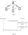
- FIG. 1 is a schematic diagram of a possible application scenario according to an aspect of the present disclosure.
- the application scenario includes a base station 110 and at least one terminal.
- a target terminal may be any terminal in the cell managed by the base station 110.
- the target terminal is denoted by a numeral 120
- other terminals different from the target terminal 120 in the cell managed by the base station 110 are all denoted by a numeral 130.
- an interaction process only between the base station 110 and the target terminal 120 is used as an example for description.
- interaction processes between the base station 110 and the other terminals 130 refer to the interaction process between the base station 110 and the target terminal 120.
- the base station 110 and a terminal communicate with each other by using an air interface technology, for example, may communicate with each other by using a cellular technology.
- the technical solutions described in the aspects of the present disclosure may be applicable to a Long Term Evolution (Long Term Evolution, LTE) system, or other wireless communications systems that use various wireless access technologies, for example, systems that use wireless access technologies such as Code Division Multiple Access (Code Division Multiple Access, CDMA), Frequency Division Multiple Access (Frequency Division Multiple Access, FDMA), Time Division Multiple Access (Time Division Multiple Access, TDMA), orthogonal frequency division multiple access (Orthogonal Frequency Division Multiple Access, OFDMA), and single carrier frequency division multiple access (Single Carrier Frequency Division Multiple Access, SC-FDMA).
- Code Division Multiple Access Code Division Multiple Access
- CDMA Code Division Multiple Access
- Frequency Division Multiple Access Frequency Division Multiple Access
- TDMA Time Division Multiple Access
- OFDMA orthogonal frequency division multiple access
- SC-FDMA single carrier frequency division multiple access
- the technical solutions may also be applicable to a subsequent evolved system of the LTE system, for example, a 5th Generation (5th Generation, 5G) system.
- a 5th Generation (5th Generation, 5G) system For clarity, only the LTE system is used as an example herein for description.
- an evolved universal terrestrial radio access network (Evolved Universal Terrestrial Radio Access Network, E-UTRAN) is used as a radio access network
- an evolved packet core (Evolved Packet Core, EPC) is used as a core network.
- EPC evolved Packet Core
- the terminal in the aspects of the present disclosure may include various handheld devices with a wireless communication function, in-vehicle devices, wearable devices, computing devices, or other processing devices connected to a wireless modem, and various forms of user equipments (User Equipment, UE), mobile stations (Mobile station, MS), terminal devices (terminal device), and the like.
- UE User Equipment
- MS Mobile station
- terminal device terminal device
- An access network device in the aspects of the present disclosure may be a base station (Base Station, BS), and the base station is an apparatus that is deployed in a radio access network and that is configured to provide a wireless communication function for a terminal.
- the base station may include various forms of macro base stations, micro base stations, relay stations, access points, and the like.
- a device with a base station function may have different names in systems that use different wireless access technologies.
- such a device is referred to as an evolved NodeB (evolved NodeB, eNB or eNodeB) in an LTE system, is referred to as a NodeB (NodeB) in a 3G communications system, and the like.
- the above-mentioned apparatuses that provide a wireless communication function for a terminal are collectively referred to as a base station or a BS.
- a same resource may be used by a plurality of terminals.
- Resource collision means that, during uplink transmission, a plurality of terminals use resources that are totally or partially the same, and as a result, a base station possibly cannot correctly obtain uplink data transmitted by some or all of the plurality of terminals.
- the base station usually considers that only one terminal uses the time-frequency resource to transmit uplink data, and uplink data transmitted by another terminal is an interference signal in this case. Consequently, a signal-to-noise ratio of the terminal is very low, and the base station cannot correctly obtain uplink data transmitted by each terminal.
- a terminal that has not successfully sent data retransmits the data, increasing a transmission delay and power consumption of the terminal.
- the aspects of the present disclosure provide a data transmission method, and a base station, a terminal, and a system that are based on the method. It should be noted that in the aspects of the present disclosure, a non-scheduled transmission solution is used for uplink transmission, and no limitation is imposed on a transmission solution used for downlink transmission.
- a core idea of the technical solutions provided in the aspects of the present disclosure is that, during uplink non-scheduled transmission, a quantity of terminals contending for a same resource is reduced to mitigate a problem of resource collision.
- terminals in a cell managed by a base station are grouped, totally or partially different resources are allocated to different groups, and terminals in a same group contend for a resource allocated to the group. In this way, a probability of resource collision during uplink non-scheduled transmission is reduced.
- the resource in the aspects of the present disclosure may be a time-frequency resource, a spreading code, a scrambling code, a timeslot, a codebook in non-orthogonal transmission, a parameter or setting in multi-user multiple input multiple output (Multi-User Multiple Input Multiple Output, MU-MIMO), or the like.
- the non-orthogonal transmission may be sparse code multiple access (Sparse Code Multiple Access, SCMA) or resource spread multiple access (Resource Spread Multiple Access, RSMA).
- the parameter or setting in the MU-MIMO may include a pilot value, a pilot cyclic shift, a case of whether an orthogonal cover code (Orthogonal Cover Code, OCC) is used, an OCC setting when the OCC is used, or a time-frequency resource, a code resource, a timeslot resource, or a codebook resource used by a pilot.
- a resource allocated to each group may be any of the foregoing resources, or may be a combination of at least two resources.
- FIG. 2 is a schematic communication diagram of a data transmission method according to an aspect of the present disclosure. The method may be applied to the application scenario shown in FIG. 1 . The method may include the following parts.
- a base station sends a grouping instruction to a target terminal.
- the base station broadcasts the grouping instruction in a cell in which the target terminal is located.
- the grouping instruction is used to group, in a preset grouping manner, terminals in a cell in which the target terminal is located into N groups, where totally or partially different resources are allocated to terminals in different groups of the N groups, a resource corresponding to an i th group of the N groups is used by a terminal in the i th group in uplink non-scheduled transmission, N is an integer greater than 1, and i is a positive integer less than or equal to N.
- the target terminal may be any terminal in a cell managed by the base station, such as the terminal 120 in the application scenario shown in FIG. 1 .
- the preset grouping manner includes at least one of the following: a random grouping manner, a path-loss-based grouping manner, or a beam-based grouping manner.
- the base station may further determine that the terminals in the cell in which the target terminal is located need to be grouped.
- the base station may further send, to the target terminal, at least one of the following: a manner parameter, a grouping parameter, or a resource parameter, where the manner parameter is used to indicate the preset grouping manner, the resource parameter is used to indicate a resource corresponding to each of the N groups, and the grouping parameter includes at least one of the following cases: when the preset grouping manner includes the random grouping manner, the grouping parameter includes one or both of the following: a total quantity N of the groups or an index of each of the N groups; when the preset grouping manner includes the path-loss-based grouping manner, the grouping parameter includes one or both of the following: a signal quality measurement manner, or a signal quality range corresponding to each of the N groups; and when the preset grouping manner includes the beam-based grouping manner, the grouping parameter includes one or both of the following: a correspondence between each of the N groups and a discovery signal transmitted on a beam, or an index of a beam in use.
- the manner parameter is used to indicate the preset grouping
- the target terminal determines, based on the preset grouping manner, a target group to which the target terminal belongs.
- the preset grouping manner includes the random grouping manner.
- the target terminal may randomly select a group from the N groups, as the target group.
- the preset grouping manner includes the path-loss-based grouping manner.
- the base station may send a downlink signal to the target terminal.
- the terminal may determine a signal quality range to which signal quality of the downlink signal belongs, and determine a group corresponding to the signal quality range, as the target group.
- the terminal may determine, based on a correspondence between a signal quality range and a group, the group corresponding to the signal quality range, as the target group.
- the correspondence may include at least two correspondences between signal quality ranges and groups.
- the terminal may further obtain the signal quality of the downlink signal.
- the preset grouping manner includes the beam-based grouping manner.
- the base station may transmit at least one beam in the cell in which the target terminal is located, where the at least one beam is used to transmit a discovery signal.
- the terminal may determine, based on a reception status of the discovery signal, the target group to which the target terminal belongs.
- the target terminal determines a target resource from a resource corresponding to the target group.
- the target terminal sends data to the base station by using the target resource.
- the base station receives the data that is sent by the target terminal by using the target resource.
- the base station may further obtain at least one of the following information: an uplink traffic volume of the cell, a resource usage status of the cell, an uplink traffic volume corresponding to the i th group, a usage status of the resource corresponding to the i th group, log information reported by the terminal in the i th group, or a quantity of terminals in the i th group; and based on at least one of the information, the base station may adjust the N groups or cancel grouping of the N groups.
- the terminals in the cell managed by the base station are grouped, totally or partially different resources are allocated to different groups, and terminals in a same group contend for resources allocated to the group. This mitigates a problem of resource collision that occurs when an uplink non-scheduled transmission solution is used, thereby achieving a technical effect of reducing a probability of resource collision during uplink non-scheduled transmission. Further, this mitigates a problem that a transmission delay and power consumption of the terminal increase due to resource collision.
- FIG. 3A is a schematic communication diagram of another data transmission method according to an aspect of the present disclosure.
- a target terminal is a terminal 120 is used for description. The method may include the following parts.
- a base station sends a grouping instruction to the terminal 120.
- a base station sends a grouping instruction to the terminal 120.
- the part 301 for content that is the same as or similar to the part 201 in FIG. 2 , reference may be made to detailed descriptions of the part 201.
- the base station may broadcast the grouping instruction to terminals in a cell.
- the base station 110 may broadcast the grouping instruction to the terminal 120 and the other terminals 130.
- the grouping instruction may be an on/off setting value, and the on/off setting value is "on". When the on/off setting value is "on”, it indicates that the terminals in the cell need to be grouped. When the on/off setting value is "off”, it indicates that the terminals in the cell do not need to be grouped.
- the base station may further perform the following operations.
- the base station may further send a downlink signal to the terminal 120, so that the terminal 120 determines, based on signal quality of the received downlink signal, a target group to which the terminal 120 belongs.
- the base station broadcasts the downlink signal to the terminals in the cell, so that the terminals in the cell determine, based on signal quality of the received downlink signal, groups to which the terminals respectively belong.
- the base station 110 may broadcast the downlink signal to the terminal 120 and the other terminals 130.
- the downlink signal may be an existing signal that is pre-specified in a communications system.
- the base station may send a synchronization signal to the terminal, and the terminal determines, based on the synchronization signal, the base station that serves the terminal.
- the terminal may further determine, based on signal quality of the synchronization signal, the group to which the terminal belongs.
- the downlink signal may be a pilot signal (also referred to as a reference signal) that is specially used for signal quality measurement by the terminal in the communications system, and the terminal may determine, based on signal quality of the pilot signal, the group to which the terminal belongs.
- the downlink signal may be a newly added signal in the communications system, for example, a pilot signal that is redesigned to be used by the terminal to measure signal quality.
- the base station may further transmit at least one beam in the cell in which the terminal 120 is located.
- the at least one beam is used to transmit a discovery signal, so that the terminal 120 determines, based on a reception status of the discovery signal, the target group to which the terminal 120 belongs.
- Different beams may be used to transmit a same discovery signal or different discovery signals.
- the base station may transmit different beams by using the plurality of antennas.
- the plurality of beams may be transmitted in a polling manner.
- a first beam is transmitted first, and after a period of time, transmission of the first beam is stopped and a second beam is transmitted.
- the rest may be deduced by analogy.
- the plurality of beams are sequentially transmitted one by one in a polling period.
- the plurality of beams may be transmitted simultaneously.
- the base station may further determine whether the terminals in the cell need to be grouped. After determining that the terminals in the cell need to be grouped, the base station sends the grouping instruction to the terminal 120. In a possible implementation, the base station may determine, in the following manners, whether the terminals in the cell need to be grouped: The base station obtains a related index corresponding to the cell, and if the related index is greater than a preset threshold, the base station determines that the terminals in the cell need to be grouped. The related index corresponding to the cell is used to indicate a resource sufficiency status of the cell.
- the related index corresponding to the cell may include one or both of the following: an uplink traffic volume of the cell or a resource usage status of the cell.
- the uplink traffic volume of the cell indicates a traffic volume of uplink non-scheduled transmission in the cell.
- a manner of indicating the uplink traffic volume is not limited.
- the uplink traffic volume of the cell may be indicated by a quantity of data packets that are sent by the terminals in the cell and that are received by the base station per unit time.
- the resource usage status of the cell may be indicated by a resource utilization of the cell, where the resource utilization of the cell is a utilization of a resource used by the terminals in the cell in uplink non-scheduled transmission.
- the base station verifies, based on the uplink traffic volume of the cell and/or the resource usage status of the cell, whether the terminals in the cell need to be grouped, so that grouping triggering timing better meets a requirement and is more accurate, thereby more effectively reducing a probability of resource collision.
- the base station may alternatively verify, based on another condition, whether the terminals in the cell need to be grouped. This is not limited in this aspect. For example, a service busy period and a service idle period are preset. When the busy period is reached, the base station sends the grouping instruction to the terminal 120.
- At least one of the manner parameter, the grouping parameter, or the resource parameter may be pre-specified between the base station and the terminal.
- the base station may send, to the terminal, at least one of the manner parameter, the grouping manner, or the resource parameter.
- any one or more of the manner parameter, the grouping manner, or the resource parameter may be pre-specified, or may be sent by the base station.
- a manner of obtaining the three types of parameters by the terminal is not limited, and manners of obtaining different parameters of the three types of parameters by the terminal may be different.
- the manner parameter may include one or more parameters.
- a parameter A indicates a random grouping manner
- a parameter B indicates the path-loss-based grouping manner
- a parameter C indicates the beam-based grouping manner.
- the manner parameter may include the parameter A; and when the preset grouping manner includes one or both of the path-loss-based grouping manner and the beam-based grouping manner, the manner parameter may include the parameter B and/or the parameter C.
- the grouping parameter includes at least one of the following cases.
- some or all of the manner parameter, the grouping parameter, and the resource parameter may be obtained by the terminal in a pre-specified manner, or may be sent by the base station to the terminal. If the pre-specified manner is used, an amount of data sent by the base station may be reduced. If the parameters are sent by the base station, grouping control and resource allocation are more flexible. In addition, when the parameters are sent by the base station, the parameters may be sent to the terminal together with the grouping instruction (such as the on/off setting value), or may be sent to the terminal separately from the grouping instruction, or different parameters may be sent separately for a plurality of times. In this aspect of the present disclosure, a quantity of times and a sequence of sending the parameters are not limited.
- the terminal 120 determines, based on the preset grouping manner, the target group to which the target terminal 120 belongs.
- the part 302 for content that is the same as or similar to the part 202 shown in FIG. 2 , reference may be made to detailed descriptions of the part 202.
- the terminal 120 may randomly select a group from the N groups, as the target group.
- the total quantity N of the groups is pre-specified as 4, or the base station indicates, to the terminal 120 by using the grouping parameter, that the total quantity of the groups is 4. Then the terminal 120 randomly selects a group from the four groups, as the target group to which the terminal 120 belongs.
- the random grouping manner is relatively simple in implementation, and can ensure a relatively balanced quantity of terminals in each group.
- the terminal 120 receives the downlink signal sent by the base station, obtains the signal quality of the downlink signal, determines a signal quality range to which the signal quality belongs, and determines, based on a preset correspondence, a group corresponding to the signal quality range, as the target group.
- the preset correspondence includes at least two correspondences between signal quality ranges and groups.
- the preset correspondence may be pre-specified, or may be indicated by the base station to the terminal by using the grouping parameter. For example, the terminal 120 learns that the signal reception power of the downlink signal is -80 dBm, and division of signal quality ranges is described as an example in the part 301.
- a signal quality range to which -80 dBm belongs is the range "greater than or equal to -90 dBm and less than -70 dBm". Assuming that the range is corresponding to a group 3, the terminal 120 uses the group 3 as the target group.
- a quantity of groups may be controlled by controlling a quantity of signal quality ranges, and a terminal in each group may be controlled by controlling a start point and an end point of a signal quality range.
- a group to which a terminal belongs is related to a geographical location of the terminal.
- the terminal 120 determines, based on a reception status of the discovery signal, the target group to which the terminal 120 belongs. If the terminal 120 receives the discovery signal transmitted by the base station by using the beam, the terminal 120 determines, based on the discovery signal and according to a preset grouping rule, the target group to which the terminal 120 belongs. If the terminal 120 does not receive the discovery signal, the terminal 120 determines, according to a preset grouping rule, the target group to which the terminal 120 belongs.
- the base station is configured to transmit at least one beam to the cell managed by the base station, and different beams are used to transmit a same discovery signal or different discovery signals.
- the preset grouping rule specifies a correspondence between a reception status of a discovery signal and a group.
- the base station transmits two beams to the cell, where one beam is used to transmit a discovery signal A, and the other beam is used to transmit a discovery signal B.
- the preset grouping rule may specify that: If a terminal in the cell receives neither the discovery signal A nor the discovery signal B, the terminal belongs to a group 1; if a terminal in the cell receives the discovery signal A but does not receive the discovery signal B, the terminal belongs to a group 2; and if a terminal in the cell receives the discovery signal B but does not receive the discovery signal A, the terminal belongs to a group 3.
- the path-loss-based grouping manner and the beam-based grouping manner can implement targeted control over a terminal or some terminals entering a target group, and implement more controllable and flexible grouping.
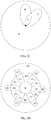
- FIG. 3B is a schematic diagram of dividing a cell into several areas in the beam-based grouping manner.
- a base station transmits three beams to the cell. Each beam includes two main lobes, and the three beams divide the cell into four areas A, B, C, and D. If a terminal receives a discovery signal transmitted on a beam, it indicates that the terminal is located in an area covered by the beam. If the terminal receives no discovery signal, it indicates that the terminal is located in an area beyond coverage of the beam, that is, the area D in FIG. 3B . Terminals located in different areas are grouped into different groups. As shown in FIG. 3B , the three beams group terminals in the cell into four groups.
- a group 1 includes a terminal in the area A
- a group 2 includes a terminal in the area B
- a group 3 includes a terminal in the area C
- a group 4 includes a terminal in the area D.
- the base station transmits a plurality of beams in a polling manner
- a terminal determines that the terminal is located in an area beyond coverage of the beam.
- the polling period may be pre-specified, or may be indicated by the base station to the terminal.
- a plurality of beams for example, the three beams shown in FIG. 3B
- the base station purposely controls, according to a stipulation pre-specified in a protocol, a plurality of beams to be used to transmit a same discovery signal, so that terminals in an area covered by the plurality of beams belong to a same group.
- the base station may also purposely control the plurality of beams to be used to transmit different discovery signals, to adjust terminal grouping.
- a beam-forming mechanism determines that a same discovery signal is transmitted on a plurality of beams. In this case, the discovery signal transmitted on the beams is determined by the beam-forming mechanism, and cannot be adaptively changed by the base station.
- the terminal when determining whether the terminal receives the discovery signal, the terminal may consider signal quality of the discovery signal. Specifically, after detecting a discovery signal, the terminal obtains signal quality of the discovery signal. If the signal quality of the discovery signal is greater than a preset threshold, the terminal determines that the discovery signal is received. Otherwise, if the signal quality of the discovery signal is less than a preset threshold, the terminals determines that the discovery signal is not received.
- FIG. 3C is a schematic diagram of dividing a cell into several areas in the beam-based grouping manner.
- a base station transmits two beams to a cell, where an area covered by one beam is A, an area covered by the other beam is B, and there is an overlapped area C.
- an overlapped area of areas covered by a plurality of beams is included in an area covered by one of the plurality of beams.
- the overlapped area C is included in the area A.
- the two beams shown in FIG. 3C divide the cell into three areas: the area A, an area different from the area C in the area B, and an area D.
- the two beams group terminals in the cell into three groups.
- an overlapped area of areas covered by a plurality of beams serves as an independent area.
- the overlapped area C serves as an independent area.
- the two beams shown in FIG. 3C divide the cell into four areas: an area different from the area C in the area A, an area different from the area C in the area B, the area C, and an area D.
- the two beams group terminals in the cell into four groups.
- one grouping manner or a combination of a plurality of grouping manners may be used.
- each signal quality range is corresponding to one or more groups.
- a reception status of each discovery signal is corresponding to one or more groups.
- the terminal 120 may obtain, based on the preset correspondence, one or more groups corresponding to the signal quality range.
- the terminal 120 determines, based on the reception status of the discovery signal and according to the preset grouping rule, one or more groups corresponding to the reception status of the discovery signal.
- the terminal 120 uses a public group of the one or more groups corresponding to the signal quality range and the one or more groups corresponding to the reception status of the discovery signal, as the target group to which the terminal 120 belongs. As shown in FIG. 3D, FIG.
- 3D is a schematic diagram of dividing a cell into several areas by using a combination of the path-loss-based grouping manner and the beam-based grouping manner.
- a combination of a letter and a numeral is used to indicate an area, and each area is corresponding to one group.
- the terminal 120 After determining the signal quality range to which the signal quality of the downlink signal belongs, the terminal 120 obtains, based on the preset correspondence, one or more groups corresponding to the signal quality range, and the terminal 120 randomly selects, from the one or more groups corresponding to the signal quality range, one group as the target group to which the terminal 120 belongs.
- the terminal 120 may determine, based on the reception status of the discovery signal and according to the preset grouping rule, one or more groups corresponding to the reception status of the discovery signal, and the terminal 120 randomly selects, from the one or more groups corresponding to the reception status of the discovery signal, one group as the target group to which the terminal 120 belongs.
- the terminal 120 may obtain a public group (each public group includes one or more groups) by using the manner described in the foregoing first example, and then randomly select, from the public group, one group as the target group to which the terminal 120 belongs.
- the cell may be divided into more areas by using a combination of a plurality of grouping manners, so as to implement more refined and diversified grouping of the terminals in the cell.
- the terminal 120 determines a target resource from a resource corresponding to the target group.
- Totally or partially different resources are allocated to terminals in different groups of the N groups.
- a resource corresponding to each of the N groups may be pre-specified, or may be indicated by the base station to the terminal by using a resource parameter.
- a resource includes two items: a time-frequency resource and a pilot cyclic shift. It is assumed that one subframe or one frame includes a total of four time-frequency resources: A1, A2, A3, and A4. Each time-frequency resource includes several symbols (for example, single carrier frequency division multiple access (Single Carrier Frequency Division Multiple Access, SC-FDMA) symbols and orthogonal frequency division multiplexing (Orthogonal Frequency Division Multiplexing, OFDM) symbols) and subcarriers. In addition, it is assumed that there are a total of four pilot cyclic shifts: B1, B2, B3, and B4.
- SC-FDMA single carrier frequency division multiple access
- OFDM Orthogonal Frequency Division Multiplexing
- Table-1 Group Number Resource 1 (1) A1+B1, (2) A3+B1, (3) A1+B2, (4) A3+B2 2 (1) A1+B3, (2) A3+B3, (3) A1+B4, (4) A3+B4 3 (1) A2+B1, (2) A4+B1, (3) A2+B2, (4) A4+B2 4 (1) A2+B3, (2) A4+B3, (3) A2+B4, (4) A4+B4
- the terminal 120 determines that the target group to which the terminal 120 belongs is a group 1, the terminal 120 selects one resource combination from the four resource combinations (1) A1+B1, (2) A3+B1, (3) A1+B2, and (4) A3+B2, as the target resource.
- the base station can parse out signals of two terminals by using an MU-MIMO technology, provided that combinations of time-frequency resources and pilot cyclic shifts used by the two terminals are not completely the same, to be specific, both the time-frequency resources and the pilot cyclic shifts are not the same, the time-frequency resources are the same but the pilot cyclic shifts are different, or the pilot cyclic shifts are the same but the time-frequency resources are different.
- each terminal may randomly select one resource combination from the 16 resource combinations, as the target resource. If the terminals are grouped into four groups, and four resource combinations are allocated to each group, each terminal can select one resource combination only from the four resource combinations, as the target resource. When terminals simultaneously performing uplink non-scheduled transmission are evenly distributed in each group, a probability of resource collision may be effectively reduced after the terminals and resources are grouped.
- the terminal 120 sends data to the base station by using the target resource.
- the terminal 120 when the target resource includes a time-frequency resource, the terminal 120 sends data to the base station by using the time-frequency resource. For another example, when the target resource includes a parameter or setting in MU-MIMO, the terminal 120 sends data to the base station based on the parameter or setting.
- the base station receives the data that is sent by the terminal 120 by using the target resource.
- the base station obtains at least one of the following information: an uplink traffic volume of the cell, a resource usage status of the cell, an uplink traffic volume corresponding to an i th group, a usage status of a resource corresponding to the i th group, log information reported by a terminal in the i th group, or a quantity of terminals in the i th group.
- the base station obtains a related index corresponding to the cell, and/or a related index corresponding to one or more of the N groups.
- the related index corresponding to the cell is used to indicate a resource sufficiency status of the cell.
- a related index corresponding to the i th group of the N groups is used to indicate a resource sufficiency status of the i th group.
- the related index corresponding to the cell includes one or both of the following: the uplink traffic volume of the cell or the resource usage status of the cell.
- the related index corresponding to the i th group includes one or all of the following: an uplink traffic volume corresponding to the i th group, a usage status of the resource corresponding to the i th group, log information reported by the terminal in the i th group, or a quantity of terminals in the i th group.
- the uplink traffic volume corresponding to the i th group is a traffic volume of uplink non-scheduled transmissions of the terminal in the i th group. In this aspect of the present disclosure, a manner of indicating the uplink traffic volume is not limited.
- the uplink traffic volume corresponding to the i th group may be indicated by a quantity of data packets that are sent by the terminal in the i th group and that are received by the base station per unit time.
- the usage status of the resource corresponding to the i th group may be a utilization of the resource corresponding to the i th group, that is, a utilization of a resource used by the terminal in the i th group in uplink non-scheduled transmission.
- the terminal 120 is used as an example.
- Log information reported by the terminal 120 may include a quantity of transmission failures of the terminal 120 in a past target time period, a range (for example, less than five times, six to 10 times, or more than 10 times) of a quantity of transmission failures of the terminal 120 in a past target time period, or a quantity of transmission failures of the terminal 120 in a past target time period and a resource that is used when transmission fails.
- a terminal may also report, to the base station, a group to which the terminal belongs, and the base station collects statistics about groups to which all the terminals belong, and determines a quantity of terminals in each group.
- the terminal may directly report, to the base station, the group to which the terminal belongs, or may notify, by reporting other equivalent information to the base station, the base station of the group to which the terminal belongs. For example, when the path-loss-based grouping manner is used, the terminal reports, to the base station, the signal quality of the downlink signal. For another example, when the beam-based grouping manner is used, the terminal reports, to the base station, a beam that covers the terminal.
- the base station does not require that all the terminals in the cell possess the capability of reporting information to the base station.
- a type of terminal reports information to the base station.
- the base station may also determine, based on a resource used by the terminal 120, the group to which the terminal 120 belongs.
- resources allocated to different groups may be partially the same, for example, resources allocated to a group 1 include resources 1, 2, 3, and 4, resources allocated to a group 2 include resources 3, 4, 5, and 6, and resources allocated to a group 3 include resources 1, 2, 5, and 6. Therefore, based only on the resource used by the terminal 120, the base station cannot accurately determine the target group to which the terminal 120 belongs.
- the base station may more accurately determine the target group to which the terminal 120 belongs, with reference to a signal reception power of a received uplink signal sent by the terminal 120, or a modulation and coding scheme (Modulation and Coding Scheme, MCS) used by the terminal 120.
- MCS Modulation and Coding Scheme
- the base station adjusts the N groups or cancels grouping of the N groups.
- the base station sends a grouping cancellation instruction to the terminals in the cell.
- the grouping cancellation instruction is used to cancel grouping of the terminals in the cell. For example, when the base station determines to cancel grouping of the terminals in the cell, the base station broadcasts a grouping on/off setting value to the terminals in the cell, and the on/off setting value is "off'.
- the related index corresponding to the cell is the uplink traffic volume corresponding to the cell.
- the uplink traffic volume corresponding to the cell is less than a preset threshold, it indicates that a traffic volume of uplink non-scheduled transmission is relatively small, and a probability of resource collision between the terminals in the cell is relatively low.
- the base station sends the grouping cancellation instruction to the terminals in the cell.
- the base station sends the grouping cancellation instruction to the terminals in the cell.
- the first thresholds respectively corresponding to the groups may be the same or may be different, and the first thresholds may be pre-specified.
- the related index corresponding to each group is an uplink traffic volume corresponding to each group.
- the base station sends the grouping cancellation instruction to the terminals in the cell.
- the related index corresponding to each group is a quantity of terminals in each group. When the quantity of terminals in each group is less than a first quantity threshold corresponding to the group, the base station sends the grouping cancellation instruction to the terminals in the cell.
- Processing overheads of the base station and the terminal can be reduced to some extent by canceling grouping. For example, if the path-loss-based grouping manner is used, the base station needs to send a downlink signal to the terminals in the cell, and the terminal needs to obtain signal quality of the downlink signal to determine the target group to which the terminal belongs. After grouping is canceled, the base station and the terminal do not need to perform the foregoing operations. Therefore, processing overheads of the base station and the terminal are reduced.
- the base station controls the quantity of terminals in the i th group to decrease, and/or controls the resource corresponding to the i th group to increase.
- Second thresholds respectively corresponding to the groups may be the same or may be different, and the second thresholds may be pre-specified.
- the related index corresponding to the i th group is a utilization of the resource corresponding to the i th group.
- the base station controls the quantity of terminals in the i th group to decrease, and/or controls the resource corresponding to the i th group to increase.
- the base station may reduce the quantity of terminals in the i th group by adjusting a beam direction or a beam width.
- the base station may allocate more resources to the i th group.
- the related index corresponding to the i th group is the quantity of terminals in the i th group.
- the base station controls the quantity of terminals in the i th group to decrease, and/or controls the resource corresponding to the i th group to increase.
- the base station controls the quantity of terminals in the i th group to decrease, and/or controls the resource corresponding to the i th group to increase. In this way, a quantity of terminals contending for a resource is reduced, and a probability of resource collision is reduced.
- the base station may also send the grouping cancellation instruction to the terminals in the cell.
- the grouping cancellation instruction is used to cancel grouping of the terminals in the cell.
- the base station may not be able to control, in a targeted manner, the quantity of terminals in the i th group to decrease, and a majority of resources may have been allocated to the i th group and a terminal in another group cannot have a necessary resource for data transmission. Therefore, when the related index corresponding to the i th group is greater than the second threshold, the base station may also cancel grouping, so as to ensure that the terminals can normally obtain a resource through contention.
- the base station can dynamically adjust, based on a resource usage status of each group, terminal grouping and resource allocation, so as to implement proper utilization of resources.
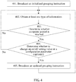
- FIG. 4 is a schematic flowchart of another data transmission method according to an aspect of the present disclosure.
- the method shown in FIG. 4 may be executed by a base station.
- a base station broadcasts an initialized grouping instruction to terminals in a cell.
- the initialized grouping instruction includes at least a default on/off setting value.
- the default on/off setting value may be set to "on", or may be set to "off'.
- the base station broadcasts the default on/off setting value to the terminals in the cell, and the on/off setting value is "on".
- the base station may further broadcast at least one of the following parameters: a manner parameter, a grouping parameter, or a resource parameter.
- the base station obtains at least one type of information.
- the at least one type of information includes one or both of the following: an uplink traffic volume of the cell or a resource usage status of the cell.
- the at least one type of information includes one or all of the following: an uplink traffic volume of the cell, a resource usage status of the cell, an uplink traffic volume corresponding to an i th group, a usage status of a resource corresponding to the i th group, log information reported by a terminal in the i th group, or a quantity of terminals in the i th group.
- the base station determines whether an update period is reached. If yes, a part 404 is performed; or if no, the part 402 is performed again.
- the update period is a time period for updating the grouping instruction, for example, may be five minutes or any other time period.
- the base station determines, based on obtained information, whether the on/off setting value needs to be changed. Alternatively, the base station may determine whether to change at least one of the manner parameter, the grouping parameter, or the resource parameter. If yes, a part 405 is performed; or if no, the part 402 is performed again.
- the base station broadcasts an updated grouping instruction to the terminals in the cell, and performs the part 402 again.
- the base station may further broadcast at least one of an updated manner parameter, an updated grouping parameter, or an updated resource parameter.
- the terminals in the cell managed by the base station are grouped, totally or partially different resources are allocated to different groups, and terminals in a same group contend for a resource allocated to the group.
- manners in which the terminal reports information to the base station include the following two manners (the "information" in this aspect may be the log information described in the part 305 in FIG. 3A , or may be other information such as a group to which the terminal belongs): Manner 1: The terminal sends, to the base station by using a particular resource, a preamble (preamble) in a particular format, and adds the information to the preamble to send the information to the base station.
- a preamble preamble
- the log information includes only a range to which a quantity of transmission failures in a past target time period belongs.
- a communications system for example, an LTE system
- an air interface technology for example, SC-FDMA and OFDM
- the terminal reports, to the base station by sending the preamble, the range to which the quantity of transmission failures in the past target time period belongs.
- a Zadoff-Chu sequence may be used as the preamble.
- a cyclic shift is a parameter of the preamble.
- the terminal randomly selects the cyclic shift, and then sends the preamble. The sending may be performed only on a specified time-frequency resource.
- uplink non-scheduled transmission does not require the terminal to send the preamble to the base station to complete random access.
- the terminal reports, to the base station by sending the preamble, the range to which the quantity of transmission failures in the past target time period belongs.
- TTI Transmission Time Interval
- the eight cyclic shifts are grouped into four groups, two in each group. All the group of cyclic shifts indicate different ranges of the quantity of transmission failures, for example, respectively indicate that the quantity of transmission failures is 0 (that is, no failure), the quantity of transmission failures is 1, the quantity of transmission failures is 2, and the quantity of transmission failures is greater than 2.
- the terminal randomly selects a cyclic shift from a corresponding group based on the quantity of transmission failures in the past target time period, and randomly selects a time-frequency resource from two pre-specified time-frequency resources to send the preamble to the base station. Even if two terminals send the preamble in a same TTI, the base station can identify that there are two terminals sending the preamble, provided that at least one of a cyclic shift of the preamble and a time-frequency resource that are used by the two terminals is different. The base station may obtain, based on the cyclic shift of the preamble, information that the terminal expects to convey, that is, the range to which the quantity of transmission failures in the past target time period belongs.
- the base station can identify only that there is one terminal sending the preamble.
- the terminal may be grouped. For example, a terminal in some groups can send the preamble only in an odd-numbered TTI, while a terminal in other groups can send the preamble only in an even-numbered TTI.
- the preamble does not need to be sent immediately, and may be sent after a time period.
- the terminal can report, to the base station, the quantity of transmission failures in the past target time period, so that the base station adjusts, based on data reported by a plurality of terminals, terminal grouping and/or resource allocation.
- Manner 2 The terminal sends, in a pre-specified format, the information together with uplink data to the base station.
- the terminal adds, in the pre-specified format, the information to an end of the uplink data, to send the information to the base station.
- the uplink data herein is data sent by the terminal to the base station by using an uplink non-scheduled transmission mode.
- the information is transmitted to the base station together with the uplink data.
- the terminal may determine, based on a feedback from the base station (for example, a random access response (Random Access Response, RAR), an acknowledgement (Acknowledgement, ACK), or a negative acknowledgement (Negative Acknowledgement, NACK) fed back by the base station), whether the information is sent successfully.
- Log information is used as an example.
- the log information may include the quantity of transmission failures in the past target time period. After sending the log information successfully, the terminal needs to reset a counter used to collect statistics about a quantity of transmission failures.
- reporting information to the base station by the terminal may be periodically triggered.
- the terminal reports the information to the base station at a preset time interval.
- reporting information to the base station by the terminal may be triggered by an event.
- the terminal reports the information to the base station after detecting occurrence of a target event.
- the target event may be that the quantity of transmission failures in the past target time period exceeds a preset threshold.
- the base station and the terminal include a corresponding hardware structure and/or software module for performing each function.
- Units and algorithm steps in examples described with reference to the aspects disclosed in the present disclosure can be implemented by hardware or a combination of hardware and computer software in the aspects of the present disclosure. Whether a function is performed by hardware or computer software driving hardware depends on particular applications and design constraints of the technical solutions. A person skilled in the art may use different methods to implement the described functions for each particular application, but it should not be considered that the implementation goes beyond the scope of the technical solutions in the aspects of the present disclosure.
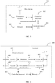
- FIG. 5 is a possible schematic structural diagram of a base station according to an aspect of the present disclosure.
- the base station 500 includes a transmitter/receiver 501 and a processor 502.
- the processor 502 may alternatively be a controller, and is denoted as a "controller/processor 502" in FIG. 5 .
- the transmitter/receiver 501 is configured to support information transmission and reception between the base station and the terminal in the foregoing aspects, and support radio communication between the terminal and another terminal.
- the processor 502 performs various functions for communicating with the terminal.
- On an uplink an uplink signal from the terminal is received by an antenna, demodulated (for example, a high-frequency signal is demodulated into a baseband signal) by the receiver 501, and further processed by the processor 502 to restore service data and signaling message that are sent by the terminal.
- the processor 502 On a downlink, service data and a signaling message are processed by the processor 502, and modulated (for example, a baseband signal is modulated into a high-frequency signal) by the transmitter 501 to generate a downlink signal, and the downlink signal is transmitted to the terminal by using an antenna.
- modulated for example, a baseband signal is modulated into a high-frequency signal
- the processor 502 is further configured to perform the process 201 in FIG. 2 , processes 301, 305, and 306 in FIG. 3A , processes 401 to 405 in FIG. 4 , and/or other processes in the technical solutions described in the aspects of the present disclosure.
- the base station 500 may further include a memory 503, and the memory 503 is configured to store program code and data used for the base station 500.
- the base station may further include a communications unit 504.
- the communications unit 504 is configured to support the base station in communicating with another network entity (for example, a network device in a core network).
- another network entity for example, a network device in a core network.
- the communications unit 504 may be an S1-U interface, configured to support the base station in communicating with a serving gateway (Serving Gateway, SGW); alternatively, the communications unit 504 may be an S1-MME interface, configured to support the base station in communicating with a mobility management entity (Mobility Management Entity, MME).
- MME Mobility Management Entity
- FIG. 5 shows only a simplified design of the base station 500.
- the base station 500 may include any quantities of transmitters, receivers, processors, controllers, memories, communications units, and the like. All base stations that can implement the aspects of the present disclosure fall within the protection scope of the aspects of the present disclosure.
- FIG. 6 is a simplified schematic diagram of a possible design structure of a terminal according to an aspect of the present disclosure.
- the terminal 600 includes a transmitter 601, a receiver 602, and a processor 603.
- the processor 603 may alternatively be a controller, and is denoted as a "controller/processor 603" in FIG. 6 .
- the terminal 600 may further include a modem processor 605, and the modem processor 605 may include an encoder 606, a modulator 607, a decoder 608, and a demodulator 609.
- the transmitter 601 adjusts (for example, performs digital-to-analog conversion, filtering, amplification, and up-conversion on) the output sample, and generates an uplink signal.
- the uplink signal is transmitted to the base station in the foregoing aspects by using an antenna.
- an antenna receives a downlink signal transmitted by the base station in the foregoing aspects.
- the receiver 602 adjusts (for example, filters, amplifies, down-converts, and digitalizes) the signal received from the antenna and provides an input sample.
- the encoder 606 receives service data and a signaling message that are to be sent on an uplink, and processes (for example, formats, encodes, and interleaves) the service data and the signaling message.
- the modulator 607 further processes (for example, performs symbol mapping and modulation on) encoded service data and an encoded signaling message, and provides an output sample.
- the demodulator 609 processes (for example, demodulates) the output sample and provides symbol estimation.
- the decoder 608 processes (for example, de-interleaves and decodes) the symbol estimation and provides the decoded data and the decoded signaling message that are sent to the terminal 600.
- the encoder 606, the modulator 607, the demodulator 609, and the decoder 608 may be implemented by the combined modem processor 605. These units perform processing according to a wireless access technology (for example, an access technology used by an LTE system and other evolved systems) used by a radio access network. It should be noted that when the terminal 600 does not include the modem processor 605, the foregoing functions of the modem processor 605 may be alternatively completed by the processor 603.
- a wireless access technology for example, an access technology used by an LTE system and other evolved systems
- the processor 603 controls and manages an action of the terminal 600 and is configured to perform processing processes implemented by the terminal 600 in the foregoing aspects of the present disclosure.
- the processor 603 is further configured to perform processes 202 to 204 in FIG. 2 , processes 302 to 304 in FIG. 3 , and/or other processes in the technical solutions described in this application.
- the base station 600 may further include a memory 604, and the memory 604 is configured to store program code and data used for the terminal 600.
- the processor configured to perform functions of the foregoing base station or terminal in the aspects of the present disclosure may be a central processing unit (Central Processing Unit, CPU), a general-purpose processor, a digital signal processor (Digital Signal Processor, DSP), an application-specific integrated circuit (Application-Specific Integrated Circuit, ASIC), a field programmable gate array (Field Programmable Gate Array, FPGA) or another programmable logic device, a transistor logic device, a hardware component, or any combination thereof.
- the processor can implement or execute various logical blocks, modules, and circuits that are described as examples with reference to the content disclosed in the aspects of the present disclosure.
- the processor may be a combination implementing a computing function, for example, a combination that includes one or more microprocessors, or a combination of a DSP and a microprocessor.
- the software instruction may include a corresponding software module.
- the software module may be stored in a random access memory (Random Access Memory, RAM), a flash memory, a read-only memory (Read Only Memory, ROM), an erasable programmable read-only memory (Erasable Programmable ROM, EPROM), an electrically erasable programmable read-only memory (Electrically EPROM, EEPROM), a register, a hard disk, a removable hard disk, a compact disc read-only memory (CD-ROM), or a storage medium in any other form that is well known in the art.
- a storage medium used as an example is coupled to the processor, so that the processor can read information from the storage medium, and can write information into the storage medium.
- the storage medium may be a constituent part of the processor.
- the processor and the storage medium may be located in an ASIC.
- the ASIC may be located in a base station or a terminal.
- the processor and the storage medium may exist in the base station or the terminal as discrete components.
- the functions described in the aspects of the present disclosure may be implemented by using hardware, software, firmware, or any combination thereof.
- these functions may be stored in a computer-readable medium or transmitted as one or more instructions or code in the computer-readable medium.
- the computer-readable medium includes a computer storage medium and a communications medium, where the communications medium includes any medium that facilitates transmission of a computer program from one place to another.
- the storage medium may be any available medium accessible to a general-purpose or special-purpose computer.
Landscapes
- Engineering & Computer Science (AREA)
- Computer Networks & Wireless Communication (AREA)
- Signal Processing (AREA)
- Multimedia (AREA)
- Quality & Reliability (AREA)
- Databases & Information Systems (AREA)
- Mobile Radio Communication Systems (AREA)
Description
- The present disclosure relates to the field of communications technologies, and in particular, to a data transmission method, an apparatus, and a system.
- With development of communications technologies, an increasing quantity of terminals need to access a wireless network, and it is difficult for the network to allocate a fixed resource to each terminal for data transmission. Therefore, the terminals share some resources for data transmission. For example, the terminals transmit data by using a non-contention based uplink transmission solution. The non-contention based transmission solution is also referred to as a scheduling-based uplink transmission solution or an uplink scheduled transmission solution, and indicates that a terminal transmits data after obtaining a dedicated resource allocated by a base station. However, in such a scheme, a large amount of signaling interaction is required, overheads are relatively high, and transmission efficiency is relatively low. Against this background, a contention-based uplink transmission solution is proposed. The contention-based uplink transmission solution is also referred to as a non-scheduling based uplink transmission solution or an uplink non-scheduled transmission solution, and indicates that a terminal needs to contend with another terminal for an available resource for data transmission, instead of using a dedicated resource for data transmission.
- However, in the uplink non-scheduled transmission solution, a same resource may be used by a plurality of terminals. This leads to a problem of resource collision.
-
US 2011/0243080 relates to methods of contention-based transmission.US 2011/0321050 relates to method and apparatus for providing shared scheduling request resources. - The present disclosure provides a solution to mitigate a problem of resource collision that occurs when an uplink non-scheduled transmission solution is used.
- Various aspects of the present disclosure have been defined in the independent claims. Further technical features of each of these aspects have been defined in the respective dependent claims.
- Based on an aspect of the present disclosure, the terminals in the cell managed by the base station are grouped, totally or partially different resources are allocated to different groups, and terminals in a same group contend for a resource allocated to the group. This mitigates a problem of resource collision that occurs when an uplink non-scheduled transmission solution is used, thereby reducing a probability of resource collision during uplink non-scheduled transmission. Further, this mitigates a problem that a transmission delay and power consumption of the terminal increase due to resource collision.
- Some or all of the manner parameter, the grouping parameter, and the resource parameter may be obtained by the terminal in a pre-specified manner, or may be sent by the base station to the terminal. When the pre-specified manner is used, the solution in this aspect of the present disclosure helps reduce an amount of data sent by the base station. When the parameters are sent by the base station, grouping control and resource allocation for the terminal are more flexible in the solution in this aspect of the present disclosure.
- Compared with a solution in the prior art, in the solutions in the aspects of the present disclosure, the terminals in the cell managed by the base station are grouped, totally or partially different resources are allocated to different groups, and terminals in a same group contend for resources allocated to the group. This mitigates a problem of resource collision that occurs when an uplink non-scheduled transmission solution is used, thereby achieving a technical effect of reducing a probability of resource collision during uplink non-scheduled transmission. Further, the solutions in the aspects of the present disclosure mitigate a problem that a transmission delay and power consumption of the terminal increase due to resource collision.
- To describe the technical solutions in the aspects of the present disclosure more clearly, the following briefly describes the accompanying drawings required for describing the aspects. Apparently, the accompanying drawings in the following description show merely some aspects of the present disclosure, and a person of ordinary skill in the art may still derive other drawings from these accompanying drawings without creative efforts.
-
FIG. 1 is a schematic diagram of an application scenario according to an aspect of the present disclosure; -
FIG. 2 is a schematic communication diagram of a data transmission method according to an aspect of the present disclosure; -
FIG. 3A is a schematic communication diagram of another data transmission method according to an aspect of the present disclosure; -
FIG. 3B is a schematic diagram of a beam-based grouping manner; -
FIG. 3C is a schematic diagram of another beam-based grouping manner; -
FIG. 3D is a schematic diagram of a manner that combines a path-loss-based grouping manner and a beam-based grouping manner; -
FIG. 4 is a schematic flowchart of another data transmission method according to an aspect of the present disclosure; -
FIG. 5 is a schematic structural diagram of a base station according to an aspect of the present disclosure; and -
FIG. 6 is a schematic structural diagram of a terminal according to an aspect of the present disclosure. - To make the objectives, technical solutions, and advantages of the aspects of the present disclosure clearer, the following describes the technical solutions of the aspects of the present disclosure with reference to the accompanying drawings in the aspects of the present disclosure.
- A network architecture and a service scenario described in the aspects of the present disclosure are intended to more clearly describe the technical solutions in the aspects of the present disclosure, but are not intended to limit the technical solutions provided in the aspects of the present disclosure. A person of ordinary skill in the art may know that as the network architecture evolves and a new service scenario emerges, the technical solutions provided in the aspects of the present disclosure are also applicable to a similar technical issue.
-
FIG. 1 is a schematic diagram of a possible application scenario according to an aspect of the present disclosure. The application scenario includes abase station 110 and at least one terminal. - As shown in
FIG. 1 , there are usually a plurality of terminals, and the plurality of terminals are located in a cell managed by thebase station 110. In this aspect of the present disclosure, a target terminal may be any terminal in the cell managed by thebase station 110. For example, as shown inFIG. 1 , the target terminal is denoted by anumeral 120, and other terminals different from thetarget terminal 120 in the cell managed by thebase station 110 are all denoted by anumeral 130. In this aspect of the present disclosure, an interaction process only between thebase station 110 and thetarget terminal 120 is used as an example for description. For interaction processes between thebase station 110 and theother terminals 130, refer to the interaction process between thebase station 110 and thetarget terminal 120. - The
base station 110 and a terminal (such as theterminal 120 or the terminal 130) communicate with each other by using an air interface technology, for example, may communicate with each other by using a cellular technology. The technical solutions described in the aspects of the present disclosure may be applicable to a Long Term Evolution (Long Term Evolution, LTE) system, or other wireless communications systems that use various wireless access technologies, for example, systems that use wireless access technologies such as Code Division Multiple Access (Code Division Multiple Access, CDMA), Frequency Division Multiple Access (Frequency Division Multiple Access, FDMA), Time Division Multiple Access (Time Division Multiple Access, TDMA), orthogonal frequency division multiple access (Orthogonal Frequency Division Multiple Access, OFDMA), and single carrier frequency division multiple access (Single Carrier Frequency Division Multiple Access, SC-FDMA). In addition, the technical solutions may also be applicable to a subsequent evolved system of the LTE system, for example, a 5th Generation (5th Generation, 5G) system. For clarity, only the LTE system is used as an example herein for description. In the LTE system, an evolved universal terrestrial radio access network (Evolved Universal Terrestrial Radio Access Network, E-UTRAN) is used as a radio access network, and an evolved packet core (Evolved Packet Core, EPC) is used as a core network. - In the aspects of the present disclosure, terms "network" and "system" are often interchangeably used, but meanings of the terms can be understood by a person skilled in the art. The terminal in the aspects of the present disclosure may include various handheld devices with a wireless communication function, in-vehicle devices, wearable devices, computing devices, or other processing devices connected to a wireless modem, and various forms of user equipments (User Equipment, UE), mobile stations (Mobile station, MS), terminal devices (terminal device), and the like. For ease of description, the devices mentioned above are collectively referred to as a terminal. An access network device in the aspects of the present disclosure may be a base station (Base Station, BS), and the base station is an apparatus that is deployed in a radio access network and that is configured to provide a wireless communication function for a terminal. The base station may include various forms of macro base stations, micro base stations, relay stations, access points, and the like. A device with a base station function may have different names in systems that use different wireless access technologies. For example, such a device is referred to as an evolved NodeB (evolved NodeB, eNB or eNodeB) in an LTE system, is referred to as a NodeB (NodeB) in a 3G communications system, and the like. For ease of description, in the aspects of the present disclosure, the above-mentioned apparatuses that provide a wireless communication function for a terminal are collectively referred to as a base station or a BS.
- In an existing uplink non-scheduled transmission solution, a same resource may be used by a plurality of terminals. This leads to a problem of resource collision. Resource collision means that, during uplink transmission, a plurality of terminals use resources that are totally or partially the same, and as a result, a base station possibly cannot correctly obtain uplink data transmitted by some or all of the plurality of terminals. For example, when the plurality of terminals use a same time-frequency resource during uplink transmission, the base station usually considers that only one terminal uses the time-frequency resource to transmit uplink data, and uplink data transmitted by another terminal is an interference signal in this case. Consequently, a signal-to-noise ratio of the terminal is very low, and the base station cannot correctly obtain uplink data transmitted by each terminal. In addition, once a resource collision problem occurs, a terminal that has not successfully sent data retransmits the data, increasing a transmission delay and power consumption of the terminal.
- Therefore, the aspects of the present disclosure provide a data transmission method, and a base station, a terminal, and a system that are based on the method. It should be noted that in the aspects of the present disclosure, a non-scheduled transmission solution is used for uplink transmission, and no limitation is imposed on a transmission solution used for downlink transmission. A core idea of the technical solutions provided in the aspects of the present disclosure is that, during uplink non-scheduled transmission, a quantity of terminals contending for a same resource is reduced to mitigate a problem of resource collision. For example, in the solutions in the aspects of the present disclosure, terminals in a cell managed by a base station are grouped, totally or partially different resources are allocated to different groups, and terminals in a same group contend for a resource allocated to the group. In this way, a probability of resource collision during uplink non-scheduled transmission is reduced.
- The resource in the aspects of the present disclosure may be a time-frequency resource, a spreading code, a scrambling code, a timeslot, a codebook in non-orthogonal transmission, a parameter or setting in multi-user multiple input multiple output (Multi-User Multiple Input Multiple Output, MU-MIMO), or the like. For example, the non-orthogonal transmission may be sparse code multiple access (Sparse Code Multiple Access, SCMA) or resource spread multiple access (Resource Spread Multiple Access, RSMA). For another example, the parameter or setting in the MU-MIMO may include a pilot value, a pilot cyclic shift, a case of whether an orthogonal cover code (Orthogonal Cover Code, OCC) is used, an OCC setting when the OCC is used, or a time-frequency resource, a code resource, a timeslot resource, or a codebook resource used by a pilot. In the aspects of the present disclosure, a resource allocated to each group may be any of the foregoing resources, or may be a combination of at least two resources.
- The following further describes the aspects of the present disclosure in detail based on common aspects of the aspects of the present disclosure.
-
FIG. 2 is a schematic communication diagram of a data transmission method according to an aspect of the present disclosure. The method may be applied to the application scenario shown inFIG. 1 . The method may include the following parts. - In a
part 201, a base station sends a grouping instruction to a target terminal. For example, the base station broadcasts the grouping instruction in a cell in which the target terminal is located. - The grouping instruction is used to group, in a preset grouping manner, terminals in a cell in which the target terminal is located into N groups, where totally or partially different resources are allocated to terminals in different groups of the N groups, a resource corresponding to an ith group of the N groups is used by a terminal in the ith group in uplink non-scheduled transmission, N is an integer greater than 1, and i is a positive integer less than or equal to N.
- The target terminal may be any terminal in a cell managed by the base station, such as the terminal 120 in the application scenario shown in
FIG. 1 . - In an example, the preset grouping manner includes at least one of the following: a random grouping manner, a path-loss-based grouping manner, or a beam-based grouping manner.
- In another example, before sending the grouping instruction to the target terminal, the base station may further determine that the terminals in the cell in which the target terminal is located need to be grouped.
- In still another example, the base station may further send, to the target terminal, at least one of the following: a manner parameter, a grouping parameter, or a resource parameter, where the manner parameter is used to indicate the preset grouping manner, the resource parameter is used to indicate a resource corresponding to each of the N groups, and the grouping parameter includes at least one of the following cases: when the preset grouping manner includes the random grouping manner, the grouping parameter includes one or both of the following: a total quantity N of the groups or an index of each of the N groups; when the preset grouping manner includes the path-loss-based grouping manner, the grouping parameter includes one or both of the following: a signal quality measurement manner, or a signal quality range corresponding to each of the N groups; and when the preset grouping manner includes the beam-based grouping manner, the grouping parameter includes one or both of the following: a correspondence between each of the N groups and a discovery signal transmitted on a beam, or an index of a beam in use.
- In a
part 202, the target terminal determines, based on the preset grouping manner, a target group to which the target terminal belongs. - In an example, the preset grouping manner includes the random grouping manner. For example, in this manner, the target terminal may randomly select a group from the N groups, as the target group.
- In another example, the preset grouping manner includes the path-loss-based grouping manner. In this manner, the base station may send a downlink signal to the target terminal. Correspondingly, after receiving the downlink signal sent by the base station, the terminal may determine a signal quality range to which signal quality of the downlink signal belongs, and determine a group corresponding to the signal quality range, as the target group. For example, the terminal may determine, based on a correspondence between a signal quality range and a group, the group corresponding to the signal quality range, as the target group. The correspondence may include at least two correspondences between signal quality ranges and groups. Further, before determining the signal quality range to which the signal quality of the downlink signal belongs, the terminal may further obtain the signal quality of the downlink signal.
- In another example, the preset grouping manner includes the beam-based grouping manner. For example, in this manner, the base station may transmit at least one beam in the cell in which the target terminal is located, where the at least one beam is used to transmit a discovery signal. Correspondingly, the terminal may determine, based on a reception status of the discovery signal, the target group to which the target terminal belongs.
- In a
part 203, the target terminal determines a target resource from a resource corresponding to the target group. - In a part 204, the target terminal sends data to the base station by using the target resource.
- Correspondingly, the base station receives the data that is sent by the target terminal by using the target resource.
- In an example, the base station may further obtain at least one of the following information: an uplink traffic volume of the cell, a resource usage status of the cell, an uplink traffic volume corresponding to the ith group, a usage status of the resource corresponding to the ith group, log information reported by the terminal in the ith group, or a quantity of terminals in the ith group; and based on at least one of the information, the base station may adjust the N groups or cancel grouping of the N groups.
- In the solution provided in this aspect of the present disclosure, the terminals in the cell managed by the base station are grouped, totally or partially different resources are allocated to different groups, and terminals in a same group contend for resources allocated to the group. This mitigates a problem of resource collision that occurs when an uplink non-scheduled transmission solution is used, thereby achieving a technical effect of reducing a probability of resource collision during uplink non-scheduled transmission. Further, this mitigates a problem that a transmission delay and power consumption of the terminal increase due to resource collision.
-
FIG. 3A is a schematic communication diagram of another data transmission method according to an aspect of the present disclosure. In the method shown inFIG. 3 , for content that is the same as or similar to that in the method shown inFIG. 2 , reference may be made to detailed descriptions inFIG. 2 . Details are not described herein again. InFIG. 3A , an example in which a target terminal is a terminal 120 is used for description. The method may include the following parts. - In a
part 301, a base station sends a grouping instruction to the terminal 120. In thepart 301, for content that is the same as or similar to thepart 201 inFIG. 2 , reference may be made to detailed descriptions of thepart 201. - In an example, the base station may broadcast the grouping instruction to terminals in a cell. In the application scenario shown in
FIG. 1 , thebase station 110 may broadcast the grouping instruction to the terminal 120 and theother terminals 130. For example, the grouping instruction may be an on/off setting value, and the on/off setting value is "on". When the on/off setting value is "on", it indicates that the terminals in the cell need to be grouped. When the on/off setting value is "off", it indicates that the terminals in the cell do not need to be grouped. - In another example, when the preset grouping manner includes one or both of a path-loss-based grouping manner or a beam-based grouping manner, the base station may further perform the following operations.
- For example, when the preset grouping manner includes the path-loss-based grouping manner, the base station may further send a downlink signal to the terminal 120, so that the terminal 120 determines, based on signal quality of the received downlink signal, a target group to which the terminal 120 belongs. In a possible implementation, the base station broadcasts the downlink signal to the terminals in the cell, so that the terminals in the cell determine, based on signal quality of the received downlink signal, groups to which the terminals respectively belong. For example, in the application scenario shown in
FIG. 1 , thebase station 110 may broadcast the downlink signal to the terminal 120 and theother terminals 130. The downlink signal may be an existing signal that is pre-specified in a communications system. For example, the base station may send a synchronization signal to the terminal, and the terminal determines, based on the synchronization signal, the base station that serves the terminal. In this aspect of the present disclosure, the terminal may further determine, based on signal quality of the synchronization signal, the group to which the terminal belongs. Alternatively, the downlink signal may be a pilot signal (also referred to as a reference signal) that is specially used for signal quality measurement by the terminal in the communications system, and the terminal may determine, based on signal quality of the pilot signal, the group to which the terminal belongs. Alternatively, the downlink signal may be a newly added signal in the communications system, for example, a pilot signal that is redesigned to be used by the terminal to measure signal quality. - For another example, when the preset grouping manner includes the beam-based grouping manner, the base station may further transmit at least one beam in the cell in which the terminal 120 is located. The at least one beam is used to transmit a discovery signal, so that the terminal 120 determines, based on a reception status of the discovery signal, the target group to which the terminal 120 belongs. Different beams may be used to transmit a same discovery signal or different discovery signals. When the base station has a plurality of antennas, the base station may transmit different beams by using the plurality of antennas. When the base station needs to transmit a plurality of beams, the plurality of beams may be transmitted in a polling manner. To be specific, a first beam is transmitted first, and after a period of time, transmission of the first beam is stopped and a second beam is transmitted. The rest may be deduced by analogy. In other words, the plurality of beams are sequentially transmitted one by one in a polling period. Alternatively, the plurality of beams may be transmitted simultaneously.
- In still another example, before sending the grouping instruction to the terminal 120, the base station may further determine whether the terminals in the cell need to be grouped. After determining that the terminals in the cell need to be grouped, the base station sends the grouping instruction to the terminal 120. In a possible implementation, the base station may determine, in the following manners, whether the terminals in the cell need to be grouped: The base station obtains a related index corresponding to the cell, and if the related index is greater than a preset threshold, the base station determines that the terminals in the cell need to be grouped. The related index corresponding to the cell is used to indicate a resource sufficiency status of the cell. The related index corresponding to the cell may include one or both of the following: an uplink traffic volume of the cell or a resource usage status of the cell. The uplink traffic volume of the cell indicates a traffic volume of uplink non-scheduled transmission in the cell. In this aspect of the present disclosure, a manner of indicating the uplink traffic volume is not limited. For example, the uplink traffic volume of the cell may be indicated by a quantity of data packets that are sent by the terminals in the cell and that are received by the base station per unit time. For another example, the resource usage status of the cell may be indicated by a resource utilization of the cell, where the resource utilization of the cell is a utilization of a resource used by the terminals in the cell in uplink non-scheduled transmission.
- In the foregoing manner, the base station verifies, based on the uplink traffic volume of the cell and/or the resource usage status of the cell, whether the terminals in the cell need to be grouped, so that grouping triggering timing better meets a requirement and is more accurate, thereby more effectively reducing a probability of resource collision. Certainly, in another possible implementation, the base station may alternatively verify, based on another condition, whether the terminals in the cell need to be grouped. This is not limited in this aspect. For example, a service busy period and a service idle period are preset. When the busy period is reached, the base station sends the grouping instruction to the terminal 120.
- In still another example, at least one of the manner parameter, the grouping parameter, or the resource parameter may be pre-specified between the base station and the terminal. Alternatively, the base station may send, to the terminal, at least one of the manner parameter, the grouping manner, or the resource parameter. In other words, any one or more of the manner parameter, the grouping manner, or the resource parameter may be pre-specified, or may be sent by the base station. A manner of obtaining the three types of parameters by the terminal is not limited, and manners of obtaining different parameters of the three types of parameters by the terminal may be different.
- In a possible implementation, the manner parameter may include one or more parameters. For example, a parameter A indicates a random grouping manner, a parameter B indicates the path-loss-based grouping manner, and a parameter C indicates the beam-based grouping manner. When the preset grouping manner includes the random grouping manner, the manner parameter may include the parameter A; and when the preset grouping manner includes one or both of the path-loss-based grouping manner and the beam-based grouping manner, the manner parameter may include the parameter B and/or the parameter C.
- In another possible implementation, the grouping parameter includes at least one of the following cases.
- Case 1: When the preset grouping manner includes the random grouping manner, the grouping parameter includes one or both of the following: a total quantity N of the groups or an index of each of the N groups. For example, the total quantity of the groups is 4, and indexes of the four groups are a group 1, a group 2, a group 3, and a group 4, respectively.
- Case 2: When the preset grouping manner includes the path-loss-based grouping manner, the grouping parameter includes one or both of the following: a signal quality measurement manner, or a signal quality range corresponding to each of the N groups. The signal quality measurement manner is used to indicate which parameter is used by the terminal 120 to measure signal quality of the downlink signal, for example, may be a signal reception power on full bandwidth, a signal reception power of a special channel, and a signal reception power on a particular time-frequency resource. The signal quality range corresponding to each of the N groups may include a total quantity of ranges and a start point and an end point of each range. For example, the signal quality of the downlink signal is measured by using a signal reception power of the downlink signal, and the start and end points of each range are set to -110 dBm, -90 dBm, -70 dBm, and -50 dBm. The signal reception power is divided into five ranges: (1) less than -110 dBm; (2) greater than or equal to -110 dBm and less than -90 dBm; (3) greater than or equal to -90 dBm and less than -70 dBm; (4) greater than or equal to -70 dBm and less than -50 dBm; (5) greater than or equal to -50 dBm.
- Case 3: When the preset grouping manner includes the beam-based grouping manner, the grouping parameter includes one or both of the following: a correspondence between each of the N groups and a discovery signal transmitted on a beam, or an index of the beam in use. For example, 10 beams and discovery signals correspondingly transmitted on the 10 beams are pre-specified. However, in an actual operation process, the base station only uses five of the 10 beams, and the base station may notify the
terminal 120 of indexes of the five beams in use. In the foregoing manner, the terminal 120 may reduce a search range from 10 beams to five beams, so as to reduce complexity of searching for a beam by theterminal 120. - In this example, some or all of the manner parameter, the grouping parameter, and the resource parameter may be obtained by the terminal in a pre-specified manner, or may be sent by the base station to the terminal. If the pre-specified manner is used, an amount of data sent by the base station may be reduced. If the parameters are sent by the base station, grouping control and resource allocation are more flexible. In addition, when the parameters are sent by the base station, the parameters may be sent to the terminal together with the grouping instruction (such as the on/off setting value), or may be sent to the terminal separately from the grouping instruction, or different parameters may be sent separately for a plurality of times. In this aspect of the present disclosure, a quantity of times and a sequence of sending the parameters are not limited.
- In a
part 302, after receiving the grouping instruction sent by the base station, the terminal 120 determines, based on the preset grouping manner, the target group to which thetarget terminal 120 belongs. In thepart 302, for content that is the same as or similar to thepart 202 shown inFIG. 2 , reference may be made to detailed descriptions of thepart 202. - In an example, when the preset grouping manner is the random grouping manner, the terminal 120 may randomly select a group from the N groups, as the target group. For example, the total quantity N of the groups is pre-specified as 4, or the base station indicates, to the terminal 120 by using the grouping parameter, that the total quantity of the groups is 4. Then the terminal 120 randomly selects a group from the four groups, as the target group to which the terminal 120 belongs. The random grouping manner is relatively simple in implementation, and can ensure a relatively balanced quantity of terminals in each group.
- In another example, when the preset grouping manner includes the path-loss-based grouping manner, the terminal 120 receives the downlink signal sent by the base station, obtains the signal quality of the downlink signal, determines a signal quality range to which the signal quality belongs, and determines, based on a preset correspondence, a group corresponding to the signal quality range, as the target group. The preset correspondence includes at least two correspondences between signal quality ranges and groups. The preset correspondence may be pre-specified, or may be indicated by the base station to the terminal by using the grouping parameter. For example, the terminal 120 learns that the signal reception power of the downlink signal is -80 dBm, and division of signal quality ranges is described as an example in the
part 301. In this case, a signal quality range to which -80 dBm belongs is the range "greater than or equal to -90 dBm and less than -70 dBm". Assuming that the range is corresponding to a group 3, the terminal 120 uses the group 3 as the target group. In the path-loss-based grouping manner, a quantity of groups may be controlled by controlling a quantity of signal quality ranges, and a terminal in each group may be controlled by controlling a start point and an end point of a signal quality range. When the terminals are grouped in this manner, a group to which a terminal belongs is related to a geographical location of the terminal. - In another example, when the preset grouping manner includes the beam-based grouping manner, the terminal 120 determines, based on a reception status of the discovery signal, the target group to which the terminal 120 belongs. If the terminal 120 receives the discovery signal transmitted by the base station by using the beam, the terminal 120 determines, based on the discovery signal and according to a preset grouping rule, the target group to which the terminal 120 belongs. If the terminal 120 does not receive the discovery signal, the terminal 120 determines, according to a preset grouping rule, the target group to which the terminal 120 belongs. The base station is configured to transmit at least one beam to the cell managed by the base station, and different beams are used to transmit a same discovery signal or different discovery signals. The preset grouping rule specifies a correspondence between a reception status of a discovery signal and a group. For example, the base station transmits two beams to the cell, where one beam is used to transmit a discovery signal A, and the other beam is used to transmit a discovery signal B. In this case, the preset grouping rule may specify that: If a terminal in the cell receives neither the discovery signal A nor the discovery signal B, the terminal belongs to a group 1; if a terminal in the cell receives the discovery signal A but does not receive the discovery signal B, the terminal belongs to a group 2; and if a terminal in the cell receives the discovery signal B but does not receive the discovery signal A, the terminal belongs to a group 3.
- The path-loss-based grouping manner and the beam-based grouping manner can implement targeted control over a terminal or some terminals entering a target group, and implement more controllable and flexible grouping.
- As shown in
FIG. 3B, FIG. 3B is a schematic diagram of dividing a cell into several areas in the beam-based grouping manner. InFIG. 3B , a base station transmits three beams to the cell. Each beam includes two main lobes, and the three beams divide the cell into four areas A, B, C, and D. If a terminal receives a discovery signal transmitted on a beam, it indicates that the terminal is located in an area covered by the beam. If the terminal receives no discovery signal, it indicates that the terminal is located in an area beyond coverage of the beam, that is, the area D inFIG. 3B . Terminals located in different areas are grouped into different groups. As shown inFIG. 3B , the three beams group terminals in the cell into four groups. For example, a group 1 includes a terminal in the area A, a group 2 includes a terminal in the area B, a group 3 includes a terminal in the area C, and a group 4 includes a terminal in the area D. In addition, when the base station transmits a plurality of beams in a polling manner, if a terminal does not receive, in a polling period, any discovery signal transmitted by the base station by using a beam, the terminal determines that the terminal is located in an area beyond coverage of the beam. The polling period may be pre-specified, or may be indicated by the base station to the terminal. - It should be noted that there may be a case in which a plurality of beams, for example, the three beams shown in
FIG. 3B , are used to transmit a same discovery signal. A possible cause of the foregoing case may be that the base station purposely controls, according to a stipulation pre-specified in a protocol, a plurality of beams to be used to transmit a same discovery signal, so that terminals in an area covered by the plurality of beams belong to a same group. When necessary, the base station may also purposely control the plurality of beams to be used to transmit different discovery signals, to adjust terminal grouping. Another possible cause of the foregoing case is that a beam-forming mechanism determines that a same discovery signal is transmitted on a plurality of beams. In this case, the discovery signal transmitted on the beams is determined by the beam-forming mechanism, and cannot be adaptively changed by the base station. - It should be further noted that for any discovery signal, when determining whether the terminal receives the discovery signal, the terminal may consider signal quality of the discovery signal. Specifically, after detecting a discovery signal, the terminal obtains signal quality of the discovery signal. If the signal quality of the discovery signal is greater than a preset threshold, the terminal determines that the discovery signal is received. Otherwise, if the signal quality of the discovery signal is less than a preset threshold, the terminals determines that the discovery signal is not received.
- Optionally, areas covered by different beams may overlap each other. As shown in
FIG. 3C, FIG. 3C is a schematic diagram of dividing a cell into several areas in the beam-based grouping manner. InFIG. 3C , a base station transmits two beams to a cell, where an area covered by one beam is A, an area covered by the other beam is B, and there is an overlapped area C. In a possible implementation, an overlapped area of areas covered by a plurality of beams is included in an area covered by one of the plurality of beams. For example, the overlapped area C is included in the area A. The two beams shown inFIG. 3C divide the cell into three areas: the area A, an area different from the area C in the area B, and an area D. Correspondingly, the two beams group terminals in the cell into three groups. In another possible implementation, an overlapped area of areas covered by a plurality of beams serves as an independent area. For example, the overlapped area C serves as an independent area. In this case, the two beams shown inFIG. 3C divide the cell into four areas: an area different from the area C in the area A, an area different from the area C in the area B, the area C, and an area D. Correspondingly, the two beams group terminals in the cell into four groups. - In addition, during grouping of the terminals in the cell, one grouping manner or a combination of a plurality of grouping manners may be used. When a combination of the path-loss-based grouping manner and one or more other grouping manners is used, in the foregoing preset correspondence, each signal quality range is corresponding to one or more groups. When a combination of the beam-based grouping manner and one or more other grouping manners is used, in the foregoing preset grouping rule, a reception status of each discovery signal is corresponding to one or more groups.
- In an example, a combination of the path-loss-based grouping manner and the beam-based grouping manner is used. For example, after determining the signal quality range to which the signal quality of the downlink signal belongs, the terminal 120 may obtain, based on the preset correspondence, one or more groups corresponding to the signal quality range. In addition, the terminal 120 determines, based on the reception status of the discovery signal and according to the preset grouping rule, one or more groups corresponding to the reception status of the discovery signal. The terminal 120 uses a public group of the one or more groups corresponding to the signal quality range and the one or more groups corresponding to the reception status of the discovery signal, as the target group to which the terminal 120 belongs. As shown in
FIG. 3D, FIG. 3D is a schematic diagram of dividing a cell into several areas by using a combination of the path-loss-based grouping manner and the beam-based grouping manner. In the figure, a combination of a letter and a numeral is used to indicate an area, and each area is corresponding to one group. - In another example, a combination of the random grouping manner and the path-loss-based grouping manner is used. For example, after determining the signal quality range to which the signal quality of the downlink signal belongs, the terminal 120 obtains, based on the preset correspondence, one or more groups corresponding to the signal quality range, and the terminal 120 randomly selects, from the one or more groups corresponding to the signal quality range, one group as the target group to which the terminal 120 belongs.
- In still another example, a combination of the random grouping manner and the beam-based grouping manner is used. For example, the terminal 120 may determine, based on the reception status of the discovery signal and according to the preset grouping rule, one or more groups corresponding to the reception status of the discovery signal, and the terminal 120 randomly selects, from the one or more groups corresponding to the reception status of the discovery signal, one group as the target group to which the terminal 120 belongs.
- In still another example, a combination of the random grouping manner, the path-loss-based grouping manner, and the beam-based grouping manner is used. For example, the terminal 120 may obtain a public group (each public group includes one or more groups) by using the manner described in the foregoing first example, and then randomly select, from the public group, one group as the target group to which the terminal 120 belongs.
- The cell may be divided into more areas by using a combination of a plurality of grouping manners, so as to implement more refined and diversified grouping of the terminals in the cell.
- In a
part 303, the terminal 120 determines a target resource from a resource corresponding to the target group. - Totally or partially different resources are allocated to terminals in different groups of the N groups. A resource corresponding to each of the N groups may be pre-specified, or may be indicated by the base station to the terminal by using a resource parameter.
- In an example, a resource includes two items: a time-frequency resource and a pilot cyclic shift. It is assumed that one subframe or one frame includes a total of four time-frequency resources: A1, A2, A3, and A4. Each time-frequency resource includes several symbols (for example, single carrier frequency division multiple access (Single Carrier Frequency Division Multiple Access, SC-FDMA) symbols and orthogonal frequency division multiplexing (Orthogonal Frequency Division Multiplexing, OFDM) symbols) and subcarriers. In addition, it is assumed that there are a total of four pilot cyclic shifts: B1, B2, B3, and B4. For example, the foregoing resources (namely, combinations of time-frequency resources and pilot cyclic shifts) are grouped into four groups, and resources of each group are shown in Table-1 below.
Table-1 Group Number Resource 1 (1) A1+B1, (2) A3+B1, (3) A1+B2, (4) A3+B2 2 (1) A1+B3, (2) A3+B3, (3) A1+B4, (4) A3+B4 3 (1) A2+B1, (2) A4+B1, (3) A2+B2, (4) A4+B2 4 (1) A2+B3, (2) A4+B3, (3) A2+B4, (4) A4+B4 - For example, when the terminal 120 determines that the target group to which the terminal 120 belongs is a group 1, the terminal 120 selects one resource combination from the four resource combinations (1) A1+B1, (2) A3+B1, (3) A1+B2, and (4) A3+B2, as the target resource.
- The base station can parse out signals of two terminals by using an MU-MIMO technology, provided that combinations of time-frequency resources and pilot cyclic shifts used by the two terminals are not completely the same, to be specific, both the time-frequency resources and the pilot cyclic shifts are not the same, the time-frequency resources are the same but the pilot cyclic shifts are different, or the pilot cyclic shifts are the same but the time-frequency resources are different.
- If the terminals and resources are not grouped, each terminal may randomly select one resource combination from the 16 resource combinations, as the target resource. If the terminals are grouped into four groups, and four resource combinations are allocated to each group, each terminal can select one resource combination only from the four resource combinations, as the target resource. When terminals simultaneously performing uplink non-scheduled transmission are evenly distributed in each group, a probability of resource collision may be effectively reduced after the terminals and resources are grouped.
- In a part 304, the terminal 120 sends data to the base station by using the target resource.
- For example, when the target resource includes a time-frequency resource, the terminal 120 sends data to the base station by using the time-frequency resource. For another example, when the target resource includes a parameter or setting in MU-MIMO, the terminal 120 sends data to the base station based on the parameter or setting.
- Correspondingly, the base station receives the data that is sent by the terminal 120 by using the target resource.
- In a
part 305, the base station obtains at least one of the following information: an uplink traffic volume of the cell, a resource usage status of the cell, an uplink traffic volume corresponding to an ith group, a usage status of a resource corresponding to the ith group, log information reported by a terminal in the ith group, or a quantity of terminals in the ith group. - The base station obtains a related index corresponding to the cell, and/or a related index corresponding to one or more of the N groups. The related index corresponding to the cell is used to indicate a resource sufficiency status of the cell. A related index corresponding to the ith group of the N groups is used to indicate a resource sufficiency status of the ith group.
- As described above, the related index corresponding to the cell includes one or both of the following: the uplink traffic volume of the cell or the resource usage status of the cell. For details, refer to the foregoing descriptions. Details are not described herein again.
- The related index corresponding to the ith group includes one or all of the following: an uplink traffic volume corresponding to the ith group, a usage status of the resource corresponding to the ith group, log information reported by the terminal in the ith group, or a quantity of terminals in the ith group. The uplink traffic volume corresponding to the ith group is a traffic volume of uplink non-scheduled transmissions of the terminal in the ith group. In this aspect of the present disclosure, a manner of indicating the uplink traffic volume is not limited. For example, the uplink traffic volume corresponding to the ith group may be indicated by a quantity of data packets that are sent by the terminal in the ith group and that are received by the base station per unit time. The usage status of the resource corresponding to the ith group may be a utilization of the resource corresponding to the ith group, that is, a utilization of a resource used by the terminal in the ith group in uplink non-scheduled transmission. The terminal 120 is used as an example. Log information reported by the terminal 120 may include a quantity of transmission failures of the terminal 120 in a past target time period, a range (for example, less than five times, six to 10 times, or more than 10 times) of a quantity of transmission failures of the terminal 120 in a past target time period, or a quantity of transmission failures of the terminal 120 in a past target time period and a resource that is used when transmission fails. In addition, a terminal may also report, to the base station, a group to which the terminal belongs, and the base station collects statistics about groups to which all the terminals belong, and determines a quantity of terminals in each group. The terminal may directly report, to the base station, the group to which the terminal belongs, or may notify, by reporting other equivalent information to the base station, the base station of the group to which the terminal belongs. For example, when the path-loss-based grouping manner is used, the terminal reports, to the base station, the signal quality of the downlink signal. For another example, when the beam-based grouping manner is used, the terminal reports, to the base station, a beam that covers the terminal.
- It should be noted that in actual application, not all terminals are required to possess a capability of reporting information to the base station. In other words, the base station does not require that all the terminals in the cell possess the capability of reporting information to the base station. For example, a type of terminal reports information to the base station.
- In addition, using the terminal 120 as an example, the base station may also determine, based on a resource used by the terminal 120, the group to which the terminal 120 belongs. In addition, resources allocated to different groups may be partially the same, for example, resources allocated to a group 1 include resources 1, 2, 3, and 4, resources allocated to a group 2 include resources 3, 4, 5, and 6, and resources allocated to a group 3 include resources 1, 2, 5, and 6. Therefore, based only on the resource used by the terminal 120, the base station cannot accurately determine the target group to which the terminal 120 belongs. In this case, if a used grouping manner is the path-loss-based grouping manner, the base station may more accurately determine the target group to which the terminal 120 belongs, with reference to a signal reception power of a received uplink signal sent by the terminal 120, or a modulation and coding scheme (Modulation and Coding Scheme, MCS) used by the
terminal 120. - In a part 306, based on at least one of the information, the base station adjusts the N groups or cancels grouping of the N groups.
- In an example, if the related index corresponding to the cell is less than a preset threshold, the base station sends a grouping cancellation instruction to the terminals in the cell. The grouping cancellation instruction is used to cancel grouping of the terminals in the cell. For example, when the base station determines to cancel grouping of the terminals in the cell, the base station broadcasts a grouping on/off setting value to the terminals in the cell, and the on/off setting value is "off'.
- For example, the related index corresponding to the cell is the uplink traffic volume corresponding to the cell. When the uplink traffic volume corresponding to the cell is less than a preset threshold, it indicates that a traffic volume of uplink non-scheduled transmission is relatively small, and a probability of resource collision between the terminals in the cell is relatively low. In this case, the base station sends the grouping cancellation instruction to the terminals in the cell.
- In another example, if related indexes corresponding to the N groups are all less than first thresholds respectively corresponding to the groups, the base station sends the grouping cancellation instruction to the terminals in the cell. The first thresholds respectively corresponding to the groups may be the same or may be different, and the first thresholds may be pre-specified.
- For example, the related index corresponding to each group is an uplink traffic volume corresponding to each group. When a traffic volume of uplink non-scheduled transmission in each group is less than a first traffic volume threshold corresponding to the group, the base station sends the grouping cancellation instruction to the terminals in the cell. For another example, the related index corresponding to each group is a quantity of terminals in each group. When the quantity of terminals in each group is less than a first quantity threshold corresponding to the group, the base station sends the grouping cancellation instruction to the terminals in the cell.
- Processing overheads of the base station and the terminal can be reduced to some extent by canceling grouping. For example, if the path-loss-based grouping manner is used, the base station needs to send a downlink signal to the terminals in the cell, and the terminal needs to obtain signal quality of the downlink signal to determine the target group to which the terminal belongs. After grouping is canceled, the base station and the terminal do not need to perform the foregoing operations. Therefore, processing overheads of the base station and the terminal are reduced.
- In still another example, if the related index corresponding to the ith group is greater than a second threshold, the base station controls the quantity of terminals in the ith group to decrease, and/or controls the resource corresponding to the ith group to increase. Second thresholds respectively corresponding to the groups may be the same or may be different, and the second thresholds may be pre-specified.
- For example, the related index corresponding to the ith group is a utilization of the resource corresponding to the ith group. When the utilization of the resource corresponding to the ith group is greater than a second utilization threshold, the base station controls the quantity of terminals in the ith group to decrease, and/or controls the resource corresponding to the ith group to increase. For example, when the beam-based grouping manner is used, the base station may reduce the quantity of terminals in the ith group by adjusting a beam direction or a beam width. Alternatively, the base station may allocate more resources to the ith group. For another example, the related index corresponding to the ith group is the quantity of terminals in the ith group. When the quantity of terminals in the ith group is greater than a second quantity threshold, the base station controls the quantity of terminals in the ith group to decrease, and/or controls the resource corresponding to the ith group to increase.
- When the related index corresponding to the ith group is greater than the second threshold, the base station controls the quantity of terminals in the ith group to decrease, and/or controls the resource corresponding to the ith group to increase. In this way, a quantity of terminals contending for a resource is reduced, and a probability of resource collision is reduced.
- Certainly, in another example, if the related index corresponding to the ith group is greater than the second threshold, the base station may also send the grouping cancellation instruction to the terminals in the cell. The grouping cancellation instruction is used to cancel grouping of the terminals in the cell. In some grouping manners, the base station may not be able to control, in a targeted manner, the quantity of terminals in the ith group to decrease, and a majority of resources may have been allocated to the ith group and a terminal in another group cannot have a necessary resource for data transmission. Therefore, when the related index corresponding to the ith group is greater than the second threshold, the base station may also cancel grouping, so as to ensure that the terminals can normally obtain a resource through contention.
- In the foregoing manner, the base station can dynamically adjust, based on a resource usage status of each group, terminal grouping and resource allocation, so as to implement proper utilization of resources.
-
FIG. 4 is a schematic flowchart of another data transmission method according to an aspect of the present disclosure. The method shown inFIG. 4 may be executed by a base station. For content that is the same as or similar to that in the method shown inFIG. 2 to FIG. 3D , refer to detailed descriptions inFIG. 2 to FIG. 3D . Details are not described herein again. - In a
part 401, a base station broadcasts an initialized grouping instruction to terminals in a cell. - The initialized grouping instruction includes at least a default on/off setting value. The default on/off setting value may be set to "on", or may be set to "off'. For example, after each restart, the base station broadcasts the default on/off setting value to the terminals in the cell, and the on/off setting value is "on". Optionally, when broadcasting the initialized grouping instruction, the base station may further broadcast at least one of the following parameters: a manner parameter, a grouping parameter, or a resource parameter.
- In a
part 402, the base station obtains at least one type of information. - When the terminals in the cell are not grouped currently, the at least one type of information includes one or both of the following: an uplink traffic volume of the cell or a resource usage status of the cell.
- When the terminals in the cell are already grouped currently, the at least one type of information includes one or all of the following: an uplink traffic volume of the cell, a resource usage status of the cell, an uplink traffic volume corresponding to an ith group, a usage status of a resource corresponding to the ith group, log information reported by a terminal in the ith group, or a quantity of terminals in the ith group.
- For descriptions related to the foregoing information, refer to detailed descriptions in the method shown in
FIG. 2 orFIG. 3A . - In a
part 403, the base station determines whether an update period is reached. If yes, apart 404 is performed; or if no, thepart 402 is performed again. - The update period is a time period for updating the grouping instruction, for example, may be five minutes or any other time period.
- In the
part 404, the base station determines, based on obtained information, whether the on/off setting value needs to be changed. Alternatively, the base station may determine whether to change at least one of the manner parameter, the grouping parameter, or the resource parameter. If yes, apart 405 is performed; or if no, thepart 402 is performed again. - In the
part 405, the base station broadcasts an updated grouping instruction to the terminals in the cell, and performs thepart 402 again. - When broadcasting the updated grouping instruction, the base station may further broadcast at least one of an updated manner parameter, an updated grouping parameter, or an updated resource parameter.
- To sum up, in the solution provided in this aspect of the present disclosure, the terminals in the cell managed by the base station are grouped, totally or partially different resources are allocated to different groups, and terminals in a same group contend for a resource allocated to the group. This mitigates a problem of resource collision that occurs when an uplink non-scheduled transmission solution is used, thereby achieving a technical effect of reducing a probability of resource collision during uplink non-scheduled transmission. Further, this mitigates a problem that a transmission delay and power consumption of the terminal increase due to resource collision.
- In an optional example provided based on the
part 305 inFIG. 3A , manners in which the terminal reports information to the base station include the following two manners (the "information" in this aspect may be the log information described in thepart 305 inFIG. 3A , or may be other information such as a group to which the terminal belongs):
Manner 1: The terminal sends, to the base station by using a particular resource, a preamble (preamble) in a particular format, and adds the information to the preamble to send the information to the base station. - This manner is applicable to a scenario in which information content is relatively simple, for example, the log information. The log information includes only a range to which a quantity of transmission failures in a past target time period belongs.
- In an example, a communications system (for example, an LTE system) that uses an air interface technology (for example, SC-FDMA and OFDM) with a time-frequency structure is used as an example. The terminal reports, to the base station by sending the preamble, the range to which the quantity of transmission failures in the past target time period belongs. In the LTE system, a Zadoff-Chu sequence may be used as the preamble. A cyclic shift is a parameter of the preamble. In the LTE system, the terminal randomly selects the cyclic shift, and then sends the preamble. The sending may be performed only on a specified time-frequency resource. It should be noted that uplink non-scheduled transmission does not require the terminal to send the preamble to the base station to complete random access. In this aspect, the terminal reports, to the base station by sending the preamble, the range to which the quantity of transmission failures in the past target time period belongs.
- It is assumed that there are eight cyclic shifts for selection, and in one transmission time interval (Transmission Time Interval, TTI), two time-frequency resources are used to send the preamble. The eight cyclic shifts are grouped into four groups, two in each group. All the group of cyclic shifts indicate different ranges of the quantity of transmission failures, for example, respectively indicate that the quantity of transmission failures is 0 (that is, no failure), the quantity of transmission failures is 1, the quantity of transmission failures is 2, and the quantity of transmission failures is greater than 2. The terminal randomly selects a cyclic shift from a corresponding group based on the quantity of transmission failures in the past target time period, and randomly selects a time-frequency resource from two pre-specified time-frequency resources to send the preamble to the base station. Even if two terminals send the preamble in a same TTI, the base station can identify that there are two terminals sending the preamble, provided that at least one of a cyclic shift of the preamble and a time-frequency resource that are used by the two terminals is different. The base station may obtain, based on the cyclic shift of the preamble, information that the terminal expects to convey, that is, the range to which the quantity of transmission failures in the past target time period belongs. If both the cyclic shift of the preamble and the time-frequency resource that are used by the two terminals are the same, the base station can identify only that there is one terminal sending the preamble. To further reduce a probability of resource collision that occurs when the terminal sends the preamble, the terminal may be grouped. For example, a terminal in some groups can send the preamble only in an odd-numbered TTI, while a terminal in other groups can send the preamble only in an even-numbered TTI. In addition, the preamble does not need to be sent immediately, and may be sent after a time period.
- In the foregoing manner, the terminal can report, to the base station, the quantity of transmission failures in the past target time period, so that the base station adjusts, based on data reported by a plurality of terminals, terminal grouping and/or resource allocation.
- Manner 2: The terminal sends, in a pre-specified format, the information together with uplink data to the base station.
- For example, the terminal adds, in the pre-specified format, the information to an end of the uplink data, to send the information to the base station. The uplink data herein is data sent by the terminal to the base station by using an uplink non-scheduled transmission mode.
- In this manner, when uplink non-scheduled transmission is successful, the information is transmitted to the base station together with the uplink data. The terminal may determine, based on a feedback from the base station (for example, a random access response (Random Access Response, RAR), an acknowledgement (Acknowledgement, ACK), or a negative acknowledgement (Negative Acknowledgement, NACK) fed back by the base station), whether the information is sent successfully. Log information is used as an example. The log information may include the quantity of transmission failures in the past target time period. After sending the log information successfully, the terminal needs to reset a counter used to collect statistics about a quantity of transmission failures.
- In addition, reporting information to the base station by the terminal may be periodically triggered. For example, the terminal reports the information to the base station at a preset time interval. Alternatively, reporting information to the base station by the terminal may be triggered by an event. To be specific, the terminal reports the information to the base station after detecting occurrence of a target event. For example, the target event may be that the quantity of transmission failures in the past target time period exceeds a preset threshold.
- The foregoing mainly describes the solutions provided in the aspects of the present disclosure from a perspective of interaction between the base station and the terminal. It can be understood that, to implement the foregoing functions, the base station and the terminal include a corresponding hardware structure and/or software module for performing each function. Units and algorithm steps in examples described with reference to the aspects disclosed in the present disclosure can be implemented by hardware or a combination of hardware and computer software in the aspects of the present disclosure. Whether a function is performed by hardware or computer software driving hardware depends on particular applications and design constraints of the technical solutions. A person skilled in the art may use different methods to implement the described functions for each particular application, but it should not be considered that the implementation goes beyond the scope of the technical solutions in the aspects of the present disclosure.
-
FIG. 5 is a possible schematic structural diagram of a base station according to an aspect of the present disclosure. - The
base station 500 includes a transmitter/receiver 501 and aprocessor 502. Theprocessor 502 may alternatively be a controller, and is denoted as a "controller/processor 502" inFIG. 5 . The transmitter/receiver 501 is configured to support information transmission and reception between the base station and the terminal in the foregoing aspects, and support radio communication between the terminal and another terminal. Theprocessor 502 performs various functions for communicating with the terminal. On an uplink, an uplink signal from the terminal is received by an antenna, demodulated (for example, a high-frequency signal is demodulated into a baseband signal) by thereceiver 501, and further processed by theprocessor 502 to restore service data and signaling message that are sent by the terminal. On a downlink, service data and a signaling message are processed by theprocessor 502, and modulated (for example, a baseband signal is modulated into a high-frequency signal) by thetransmitter 501 to generate a downlink signal, and the downlink signal is transmitted to the terminal by using an antenna. It should be noted that the demodulation or modulation functions may also be completed by theprocessor 502. For example, theprocessor 502 is further configured to perform theprocess 201 inFIG. 2 , processes 301, 305, and 306 inFIG. 3A , processes 401 to 405 inFIG. 4 , and/or other processes in the technical solutions described in the aspects of the present disclosure. - Further, the
base station 500 may further include amemory 503, and thememory 503 is configured to store program code and data used for thebase station 500. In addition, the base station may further include acommunications unit 504. Thecommunications unit 504 is configured to support the base station in communicating with another network entity (for example, a network device in a core network). For example, in an LTE system, thecommunications unit 504 may be an S1-U interface, configured to support the base station in communicating with a serving gateway (Serving Gateway, SGW); alternatively, thecommunications unit 504 may be an S1-MME interface, configured to support the base station in communicating with a mobility management entity (Mobility Management Entity, MME). - It can be understood that
FIG. 5 shows only a simplified design of thebase station 500. In actual application, thebase station 500 may include any quantities of transmitters, receivers, processors, controllers, memories, communications units, and the like. All base stations that can implement the aspects of the present disclosure fall within the protection scope of the aspects of the present disclosure. -
FIG. 6 is a simplified schematic diagram of a possible design structure of a terminal according to an aspect of the present disclosure. The terminal 600 includes atransmitter 601, areceiver 602, and aprocessor 603. Theprocessor 603 may alternatively be a controller, and is denoted as a "controller/processor 603" inFIG. 6 . Optionally, the terminal 600 may further include amodem processor 605, and themodem processor 605 may include anencoder 606, amodulator 607, adecoder 608, and ademodulator 609. - In an example, the
transmitter 601 adjusts (for example, performs digital-to-analog conversion, filtering, amplification, and up-conversion on) the output sample, and generates an uplink signal. The uplink signal is transmitted to the base station in the foregoing aspects by using an antenna. On a downlink, an antenna receives a downlink signal transmitted by the base station in the foregoing aspects. Thereceiver 602 adjusts (for example, filters, amplifies, down-converts, and digitalizes) the signal received from the antenna and provides an input sample. In themodem processor 605, theencoder 606 receives service data and a signaling message that are to be sent on an uplink, and processes (for example, formats, encodes, and interleaves) the service data and the signaling message. Themodulator 607 further processes (for example, performs symbol mapping and modulation on) encoded service data and an encoded signaling message, and provides an output sample. The demodulator 609 processes (for example, demodulates) the output sample and provides symbol estimation. Thedecoder 608 processes (for example, de-interleaves and decodes) the symbol estimation and provides the decoded data and the decoded signaling message that are sent to the terminal 600. Theencoder 606, themodulator 607, thedemodulator 609, and thedecoder 608 may be implemented by the combinedmodem processor 605. These units perform processing according to a wireless access technology (for example, an access technology used by an LTE system and other evolved systems) used by a radio access network. It should be noted that when the terminal 600 does not include themodem processor 605, the foregoing functions of themodem processor 605 may be alternatively completed by theprocessor 603. - The
processor 603 controls and manages an action of the terminal 600 and is configured to perform processing processes implemented by the terminal 600 in the foregoing aspects of the present disclosure. For example, theprocessor 603 is further configured to performprocesses 202 to 204 inFIG. 2 , processes 302 to 304 inFIG. 3 , and/or other processes in the technical solutions described in this application. - Further, the
base station 600 may further include amemory 604, and thememory 604 is configured to store program code and data used for the terminal 600. - The processor configured to perform functions of the foregoing base station or terminal in the aspects of the present disclosure may be a central processing unit (Central Processing Unit, CPU), a general-purpose processor, a digital signal processor (Digital Signal Processor, DSP), an application-specific integrated circuit (Application-Specific Integrated Circuit, ASIC), a field programmable gate array (Field Programmable Gate Array, FPGA) or another programmable logic device, a transistor logic device, a hardware component, or any combination thereof. The processor can implement or execute various logical blocks, modules, and circuits that are described as examples with reference to the content disclosed in the aspects of the present disclosure. Alternatively, the processor may be a combination implementing a computing function, for example, a combination that includes one or more microprocessors, or a combination of a DSP and a microprocessor.
- Method or algorithm steps described with reference to the content disclosed in the aspects of the present disclosure may be implemented by using hardware, or may be implemented by a processor by executing a software instruction. The software instruction may include a corresponding software module. The software module may be stored in a random access memory (Random Access Memory, RAM), a flash memory, a read-only memory (Read Only Memory, ROM), an erasable programmable read-only memory (Erasable Programmable ROM, EPROM), an electrically erasable programmable read-only memory (Electrically EPROM, EEPROM), a register, a hard disk, a removable hard disk, a compact disc read-only memory (CD-ROM), or a storage medium in any other form that is well known in the art. A storage medium used as an example is coupled to the processor, so that the processor can read information from the storage medium, and can write information into the storage medium. Certainly, the storage medium may be a constituent part of the processor. The processor and the storage medium may be located in an ASIC. In addition, the ASIC may be located in a base station or a terminal. Certainly, the processor and the storage medium may exist in the base station or the terminal as discrete components.
- A person skilled in the art should be aware that in one or more of the foregoing examples, the functions described in the aspects of the present disclosure may be implemented by using hardware, software, firmware, or any combination thereof. When the functions are implemented by software, these functions may be stored in a computer-readable medium or transmitted as one or more instructions or code in the computer-readable medium. The computer-readable medium includes a computer storage medium and a communications medium, where the communications medium includes any medium that facilitates transmission of a computer program from one place to another. The storage medium may be any available medium accessible to a general-purpose or special-purpose computer.
- In the foregoing specific implementations, the objectives, technical solutions, and beneficial effects of the present disclosure are described in more detail. It should be understood that the foregoing descriptions are merely specific implementations of the aspects of the present disclosure, but are not intended to limit the protection scope of the aspects of the present disclosure.
Claims (10)
- A data transmission method, wherein the method comprises:sending, by a base station, a grouping instruction to a target terminal, wherein the grouping instruction is used to group, in a preset grouping manner, terminals in a cell in which the target terminal is located into N groups, totally or partially different resources are allocated to terminals in different groups of the N groups, a resource corresponding to an ith group of the N groups is used by a terminal in the ith group in uplink non-scheduled transmission, N is an integer greater than 1, and i is a positive integer less than or equal to N; andreceiving, by the base station, data that is sent by the target terminal by using a target resource, wherein the target resource is a resource corresponding to a target group to which the target terminal belongs;wherein the preset grouping manner comprises a beam-based grouping manner, and the method further comprises:
transmitting, by the base station, a plurality of beams in the cell in which the target terminal is located, wherein the base station uses the plurality of beams to transmit multiple discovery signals, in order to allow the target terminal to determine, based on a reception status of the discovery signals, the target group to which the target terminal belongs, wherein different beams transmit different discovery signals. - The method according to claim 1, wherein before the sending, by a base station, a grouping instruction to a target terminal, the method further comprises:
determining, by the base station, that the terminals in the cell need to be grouped. - The method according to claim 1 or 2, wherein after the receiving, by the base station, data that is sent by the target terminal by using a target resource, the method further comprises:obtaining, by the base station, at least one of the following information: an uplink traffic volume of the cell, a resource usage status of the cell, an uplink traffic volume corresponding to the ith group, a usage status of the resource corresponding to the ith group, log information reported by the terminal in the ith group, or a quantity of terminals in the ith group; andbased on at least one of the information, adjusting, by the base station, the N groups or canceling grouping of the N groups.
- A data transmission method, wherein the method comprises:receiving, by a terminal, a grouping instruction from a base station, wherein the grouping instruction is used to group, in a preset grouping manner, terminals in a cell in which the terminal is located into N groups, totally or partially different resources are allocated to terminals in different groups of the N groups, a resource corresponding to an ith group of the N groups is used by a terminal in the ith group in uplink non-scheduled transmission, N is an integer greater than 1, and i is a positive integer less than or equal to N;determining, by the terminal based on the preset grouping manner, a target group to which the terminal belongs;determining, by the terminal, a target resource from a resource corresponding to the target group; andsending, by the terminal, data to the base station by using the target resource;wherein the preset grouping manner comprises a beam-based grouping manner, and the determining, by the terminal based on the preset grouping manner, a target group to which the terminal belongs comprises:
determining, by the terminal based on a reception status of multiple discovery signals, the target group to which the terminal belongs, wherein the multiple discovery signals are transmitted on a plurality of beams transmitted by the base station in the cell in which the terminal is located, wherein different beams transmit different discovery signals. - The method according to claim 4, wherein the method further comprises:
further receiving, by the terminal from the base station, at least one of the following: a manner parameter, a grouping parameter, or a resource parameter, wherein the manner parameter is used to indicate the preset grouping manner, the resource parameter is used to indicate a resource corresponding to each of the N groups, and the grouping parameter comprises when the preset grouping manner comprises the beam-based grouping manner, the grouping parameter comprises one or both of the following: a correspondence between each of the N groups and a discovery signal transmitted on a beam, or an index of a beam in use. - A base station, wherein the base station comprises a processor, a transmitter, and a receiver; and
the processor is configured to: send a grouping instruction to a target terminal by using the transmitter, wherein the grouping instruction is used to group, in a preset grouping manner, terminals in a cell in which the target terminal is located into N groups, totally or partially different resources are allocated to terminals in different groups of the N groups, a resource corresponding to an ith group of the N groups is used by a terminal in the ith group in uplink non-scheduled transmission, N is an integer greater than 1, and i is a positive integer less than or equal to N; and receive, by using the receiver, data that is sent by the target terminal by using a target resource, wherein the target resource is a resource corresponding to a target group to which the target terminal belongs;
wherein the preset grouping manner comprises a beam-based grouping manner, and the processor is further configured to:
transmit, by using the transmitter, a plurality of beams in the cell in which the target terminal is located, wherein the base station is configured to use the plurality of beams to transmit multiple discovery signals, in order to allow the target terminal to determine, based on a reception status of the discovery signals, the target group to which the target terminal belongs, wherein different beams transmit different discovery signals. - The base station according to claim 6, wherein the processor is further configured to:
before sending the grouping instruction to the target terminal by using the transmitter, determine that the terminals in the cell need to be grouped. - The base station according to claim 6 or 7, wherein the processor is further configured to: after receiving, by using the receiver, the data that is sent by the target terminal by using the target resource, obtain at least one of the following information: an uplink traffic volume of the cell, a resource usage status of the cell, an uplink traffic volume corresponding to the ith group, a usage status of the resource corresponding to the ith group, log information reported by the terminal in the ith group, or a quantity of terminals in the ith group; and based on at least one of the information, adjust the N groups or cancel grouping of the N groups.
- A terminal, wherein the terminal comprises a processor, a receiver, and a transmitter; and
the processor is configured to receive, by using the receiver, a grouping instruction from a base station, wherein the grouping instruction is used to group, in a preset grouping manner, terminals in a cell in which the terminal is located into N groups, totally or partially different resources are allocated to terminals in different groups of the N groups, a resource corresponding to an ith group of the N groups is used by a terminal in the ith group in uplink non-scheduled transmission, N is an integer greater than 1, and i is a positive integer less than or equal to N; determine, based on the preset grouping manner, a target group to which the terminal belongs; determine a target resource from a resource corresponding to the target group; and send, by using the transmitter, data to the base station by using the target resource;
wherein the preset grouping manner comprises a beam-based grouping manner, and the processor is specifically configured to determine, based on a reception status of multiple discovery signals, the target group to which the terminal belongs, wherein the multiple discovery signals are transmitted on a plurality of beams transmitted by the base station in the cell in which the terminal is located, wherein different beams transmit different discovery signals. - The terminal according to claim 9, wherein the processor is further configured to receive, from the base station by using the receiver, at least one of the following: a manner parameter, a grouping parameter, or a resource parameter, wherein the manner parameter is used to indicate the preset grouping manner, the resource parameter is used to indicate a resource corresponding to each of the N groups, and the grouping parameter comprises
when the preset grouping manner comprises the beam-based grouping manner, the grouping parameter comprises one or both of the following: a correspondence between each of the N groups and a discovery signal transmitted on a beam, or an index of a beam in use.
Applications Claiming Priority (1)
| Application Number | Priority Date | Filing Date | Title |
|---|---|---|---|
| PCT/CN2016/083926 WO2017206024A1 (en) | 2016-05-30 | 2016-05-30 | Data transmission method, apparatus and system |
Publications (3)
| Publication Number | Publication Date |
|---|---|
| EP3457798A1 EP3457798A1 (en) | 2019-03-20 |
| EP3457798A4 EP3457798A4 (en) | 2019-04-24 |
| EP3457798B1 true EP3457798B1 (en) | 2020-09-16 |
Family
ID=60478303
Family Applications (1)
| Application Number | Title | Priority Date | Filing Date |
|---|---|---|---|
| EP16903412.1A Active EP3457798B1 (en) | 2016-05-30 | 2016-05-30 | Data transmission method and apparatus |
Country Status (4)
| Country | Link |
|---|---|
| US (1) | US11051135B2 (en) |
| EP (1) | EP3457798B1 (en) |
| CN (1) | CN109156029B (en) |
| WO (1) | WO2017206024A1 (en) |
Families Citing this family (3)
| Publication number | Priority date | Publication date | Assignee | Title |
|---|---|---|---|---|
| JP2019050439A (en) * | 2016-01-22 | 2019-03-28 | シャープ株式会社 | Radio control station device and control method |
| WO2020062183A1 (en) | 2018-09-29 | 2020-04-02 | 北京小米移动软件有限公司 | Method and apparatus for transmitting information, and base station |
| CN115022965B (en) * | 2022-07-25 | 2024-04-09 | 中国联合网络通信集团有限公司 | Cell positioning method, device, electronic equipment and storage medium |
Family Cites Families (17)
| Publication number | Priority date | Publication date | Assignee | Title |
|---|---|---|---|---|
| JP4698418B2 (en) * | 2005-12-28 | 2011-06-08 | 株式会社エヌ・ティ・ティ・ドコモ | COMMUNICATION SYSTEM, COMMUNICATION DEVICE, COMMUNICATION METHOD, AND PROGRAM |
| KR101452489B1 (en) * | 2007-10-18 | 2014-10-21 | 엘지전자 주식회사 | Method of receiving data in wireless communication |
| KR101366285B1 (en) * | 2007-11-20 | 2014-02-20 | 엘지전자 주식회사 | Method of allocating resource for Mobile Station to support real time service |
| CN101184075B (en) * | 2007-12-13 | 2012-01-04 | 华为技术有限公司 | Frequency deviation compensation method and device |
| CN101500312B (en) * | 2008-02-01 | 2011-06-22 | 中兴通讯股份有限公司 | Available resource allocation method |
| US8295209B2 (en) * | 2008-02-21 | 2012-10-23 | Nokia Corporation | Frame structures with flexible partition boundary for wireless networks |
| US10187758B2 (en) | 2009-12-29 | 2019-01-22 | Qualcomm Incorporated | Method and apparatus for providing shared scheduling request resources |
| US8964658B2 (en) * | 2010-03-31 | 2015-02-24 | Mediatek Inc. | Methods of contention-based transmission |
| CN102291826B (en) * | 2010-06-18 | 2014-01-08 | 华为技术有限公司 | Uplink transmission method, configuration method and relevant equipment based on competition |
| CN103220788B (en) | 2012-01-19 | 2016-08-24 | 华为技术有限公司 | Method, node and the access point that node is grouped |
| CN103458420B (en) * | 2012-05-31 | 2016-12-28 | 华为技术有限公司 | A kind of wireless communications method, base station and subscriber equipment |
| CN103841603B (en) * | 2012-11-20 | 2019-05-31 | 北京三星通信技术研究有限公司 | The method and apparatus of ascending grouping scheduling |
| CN104869655B (en) | 2014-02-21 | 2019-07-23 | 株式会社Ntt都科摩 | Uplink resource dispatching method, wireless base station and mobile station |
| WO2016204370A1 (en) * | 2015-06-19 | 2016-12-22 | Lg Electronics Inc. | Method and apparatus for transmitting and receiving control information |
| ES2744183T3 (en) * | 2015-07-31 | 2020-02-24 | Intel Ip Corp | Network discovery and beam acquisition for beam cell operation |
| EP3354081B1 (en) * | 2015-09-25 | 2019-11-06 | Sony Corporation | Wireless telecommunications system |
| KR102514908B1 (en) * | 2015-12-22 | 2023-03-28 | 삼성전자 주식회사 | Method and apparatus for base station operation for d2d support in a wireless communication system |
-
2016
- 2016-05-30 EP EP16903412.1A patent/EP3457798B1/en active Active
- 2016-05-30 CN CN201680086132.8A patent/CN109156029B/en active Active
- 2016-05-30 WO PCT/CN2016/083926 patent/WO2017206024A1/en unknown
-
2018
- 2018-11-28 US US16/203,577 patent/US11051135B2/en active Active
Non-Patent Citations (1)
| Title |
|---|
| None * |
Also Published As
| Publication number | Publication date |
|---|---|
| US11051135B2 (en) | 2021-06-29 |
| EP3457798A4 (en) | 2019-04-24 |
| CN109156029B (en) | 2021-08-20 |
| EP3457798A1 (en) | 2019-03-20 |
| US20190098459A1 (en) | 2019-03-28 |
| CN109156029A (en) | 2019-01-04 |
| WO2017206024A1 (en) | 2017-12-07 |
Similar Documents
| Publication | Publication Date | Title |
|---|---|---|
| KR102352865B1 (en) | A method of monitoring control signal in wireless communication system and apparatus using the same | |
| KR102361790B1 (en) | LBT (Listen Before Talk) for wideband operation of NR unlicensed spectrum | |
| US11626952B2 (en) | Signal configuration method and related device | |
| CN107439045B (en) | Physical random access channel method in eLAA and user equipment | |
| US11038567B2 (en) | Adaptive autonomous uplink communication design | |
| KR102181920B1 (en) | Communications device and method for improving the transmission of random access messages | |
| CN105122917B (en) | Dynamic TDD configuration user equipment and method | |
| JP2019140512A (en) | Terminal device, base station device, and communication method | |
| WO2017076362A1 (en) | Systems and methods for self-contained air interface partitions | |
| CN116114192A (en) | Mechanisms and conditions for supporting repetition of PUCCH transmissions | |
| US20130064199A1 (en) | Apparatus and method for transmitting/receiving uplink power control information | |
| US11330631B2 (en) | Remote apparatus in base station, base station, and random access method | |
| US11051135B2 (en) | Data transmission method, apparatus, and system | |
| EP3493639A1 (en) | Terminal device, base station device, and communication method | |
| WO2019031141A1 (en) | Base station device and communication method | |
| KR20210135631A (en) | Sounding feedback utilizing shortened frame structures | |
| WO2019031507A1 (en) | Communication device and communication method | |
| EP3834544B1 (en) | Intra-symbol occ mapping for transmissions such as nr-u pucch transmissions | |
| WO2019031552A1 (en) | Base station device and communication method | |
| US20190281605A1 (en) | Method and apparatus for allocating resources in wireless communication system | |
| US11632775B2 (en) | Configured grant using polynomial over Galois field | |
| US11696269B2 (en) | Uplink channel repetitions with inter-BWP frequency hopping | |
| CN115842598A (en) | Communication method and device | |
| EP3182778B1 (en) | Scheduling method, system and base station for mobile networks with bursty traffic | |
| WO2022077449A1 (en) | Long physical uplink control channel (pucch) format for multi-slot transmissions |
Legal Events
| Date | Code | Title | Description |
|---|---|---|---|
| STAA | Information on the status of an ep patent application or granted ep patent |
Free format text: STATUS: THE INTERNATIONAL PUBLICATION HAS BEEN MADE |
|
| PUAI | Public reference made under article 153(3) epc to a published international application that has entered the european phase |
Free format text: ORIGINAL CODE: 0009012 |
|
| STAA | Information on the status of an ep patent application or granted ep patent |
Free format text: STATUS: REQUEST FOR EXAMINATION WAS MADE |
|
| 17P | Request for examination filed |
Effective date: 20181210 |
|
| AK | Designated contracting states |
Kind code of ref document: A1 Designated state(s): AL AT BE BG CH CY CZ DE DK EE ES FI FR GB GR HR HU IE IS IT LI LT LU LV MC MK MT NL NO PL PT RO RS SE SI SK SM TR |
|
| AX | Request for extension of the european patent |
Extension state: BA ME |
|
| A4 | Supplementary search report drawn up and despatched |
Effective date: 20190327 |
|
| RIC1 | Information provided on ipc code assigned before grant |
Ipc: H04W 74/08 20090101ALN20190321BHEP Ipc: H04W 72/02 20090101AFI20190321BHEP |
|
| DAV | Request for validation of the european patent (deleted) | ||
| DAX | Request for extension of the european patent (deleted) | ||
| REG | Reference to a national code |
Ref country code: DE Ref legal event code: R079 Ref document number: 602016044350 Country of ref document: DE Free format text: PREVIOUS MAIN CLASS: H04W0072140000 Ipc: H04W0072020000 |
|
| GRAP | Despatch of communication of intention to grant a patent |
Free format text: ORIGINAL CODE: EPIDOSNIGR1 |
|
| STAA | Information on the status of an ep patent application or granted ep patent |
Free format text: STATUS: GRANT OF PATENT IS INTENDED |
|
| RIC1 | Information provided on ipc code assigned before grant |
Ipc: H04W 74/08 20090101ALN20200319BHEP Ipc: H04W 4/08 20090101ALI20200319BHEP Ipc: H04W 72/02 20090101AFI20200319BHEP |
|
| INTG | Intention to grant announced |
Effective date: 20200401 |
|
| GRAS | Grant fee paid |
Free format text: ORIGINAL CODE: EPIDOSNIGR3 |
|
| GRAA | (expected) grant |
Free format text: ORIGINAL CODE: 0009210 |
|
| STAA | Information on the status of an ep patent application or granted ep patent |
Free format text: STATUS: THE PATENT HAS BEEN GRANTED |
|
| AK | Designated contracting states |
Kind code of ref document: B1 Designated state(s): AL AT BE BG CH CY CZ DE DK EE ES FI FR GB GR HR HU IE IS IT LI LT LU LV MC MK MT NL NO PL PT RO RS SE SI SK SM TR |
|
| REG | Reference to a national code |
Ref country code: GB Ref legal event code: FG4D |
|
| REG | Reference to a national code |
Ref country code: CH Ref legal event code: EP |
|
| REG | Reference to a national code |
Ref country code: DE Ref legal event code: R096 Ref document number: 602016044350 Country of ref document: DE |
|
| REG | Reference to a national code |
Ref country code: IE Ref legal event code: FG4D |
|
| REG | Reference to a national code |
Ref country code: AT Ref legal event code: REF Ref document number: 1315341 Country of ref document: AT Kind code of ref document: T Effective date: 20201015 |
|
| PG25 | Lapsed in a contracting state [announced via postgrant information from national office to epo] |
Ref country code: BG Free format text: LAPSE BECAUSE OF FAILURE TO SUBMIT A TRANSLATION OF THE DESCRIPTION OR TO PAY THE FEE WITHIN THE PRESCRIBED TIME-LIMIT Effective date: 20201216 Ref country code: SE Free format text: LAPSE BECAUSE OF FAILURE TO SUBMIT A TRANSLATION OF THE DESCRIPTION OR TO PAY THE FEE WITHIN THE PRESCRIBED TIME-LIMIT Effective date: 20200916 Ref country code: NO Free format text: LAPSE BECAUSE OF FAILURE TO SUBMIT A TRANSLATION OF THE DESCRIPTION OR TO PAY THE FEE WITHIN THE PRESCRIBED TIME-LIMIT Effective date: 20201216 Ref country code: GR Free format text: LAPSE BECAUSE OF FAILURE TO SUBMIT A TRANSLATION OF THE DESCRIPTION OR TO PAY THE FEE WITHIN THE PRESCRIBED TIME-LIMIT Effective date: 20201217 Ref country code: HR Free format text: LAPSE BECAUSE OF FAILURE TO SUBMIT A TRANSLATION OF THE DESCRIPTION OR TO PAY THE FEE WITHIN THE PRESCRIBED TIME-LIMIT Effective date: 20200916 Ref country code: FI Free format text: LAPSE BECAUSE OF FAILURE TO SUBMIT A TRANSLATION OF THE DESCRIPTION OR TO PAY THE FEE WITHIN THE PRESCRIBED TIME-LIMIT Effective date: 20200916 |
|
| REG | Reference to a national code |
Ref country code: AT Ref legal event code: MK05 Ref document number: 1315341 Country of ref document: AT Kind code of ref document: T Effective date: 20200916 |
|
| REG | Reference to a national code |
Ref country code: NL Ref legal event code: MP Effective date: 20200916 |
|
| PG25 | Lapsed in a contracting state [announced via postgrant information from national office to epo] |
Ref country code: LV Free format text: LAPSE BECAUSE OF FAILURE TO SUBMIT A TRANSLATION OF THE DESCRIPTION OR TO PAY THE FEE WITHIN THE PRESCRIBED TIME-LIMIT Effective date: 20200916 Ref country code: RS Free format text: LAPSE BECAUSE OF FAILURE TO SUBMIT A TRANSLATION OF THE DESCRIPTION OR TO PAY THE FEE WITHIN THE PRESCRIBED TIME-LIMIT Effective date: 20200916 |
|
| REG | Reference to a national code |
Ref country code: LT Ref legal event code: MG4D |
|
| PG25 | Lapsed in a contracting state [announced via postgrant information from national office to epo] |
Ref country code: CZ Free format text: LAPSE BECAUSE OF FAILURE TO SUBMIT A TRANSLATION OF THE DESCRIPTION OR TO PAY THE FEE WITHIN THE PRESCRIBED TIME-LIMIT Effective date: 20200916 Ref country code: RO Free format text: LAPSE BECAUSE OF FAILURE TO SUBMIT A TRANSLATION OF THE DESCRIPTION OR TO PAY THE FEE WITHIN THE PRESCRIBED TIME-LIMIT Effective date: 20200916 Ref country code: PT Free format text: LAPSE BECAUSE OF FAILURE TO SUBMIT A TRANSLATION OF THE DESCRIPTION OR TO PAY THE FEE WITHIN THE PRESCRIBED TIME-LIMIT Effective date: 20210118 Ref country code: LT Free format text: LAPSE BECAUSE OF FAILURE TO SUBMIT A TRANSLATION OF THE DESCRIPTION OR TO PAY THE FEE WITHIN THE PRESCRIBED TIME-LIMIT Effective date: 20200916 Ref country code: SM Free format text: LAPSE BECAUSE OF FAILURE TO SUBMIT A TRANSLATION OF THE DESCRIPTION OR TO PAY THE FEE WITHIN THE PRESCRIBED TIME-LIMIT Effective date: 20200916 Ref country code: EE Free format text: LAPSE BECAUSE OF FAILURE TO SUBMIT A TRANSLATION OF THE DESCRIPTION OR TO PAY THE FEE WITHIN THE PRESCRIBED TIME-LIMIT Effective date: 20200916 |
|
| PG25 | Lapsed in a contracting state [announced via postgrant information from national office to epo] |
Ref country code: AT Free format text: LAPSE BECAUSE OF FAILURE TO SUBMIT A TRANSLATION OF THE DESCRIPTION OR TO PAY THE FEE WITHIN THE PRESCRIBED TIME-LIMIT Effective date: 20200916 Ref country code: AL Free format text: LAPSE BECAUSE OF FAILURE TO SUBMIT A TRANSLATION OF THE DESCRIPTION OR TO PAY THE FEE WITHIN THE PRESCRIBED TIME-LIMIT Effective date: 20200916 Ref country code: ES Free format text: LAPSE BECAUSE OF FAILURE TO SUBMIT A TRANSLATION OF THE DESCRIPTION OR TO PAY THE FEE WITHIN THE PRESCRIBED TIME-LIMIT Effective date: 20200916 Ref country code: PL Free format text: LAPSE BECAUSE OF FAILURE TO SUBMIT A TRANSLATION OF THE DESCRIPTION OR TO PAY THE FEE WITHIN THE PRESCRIBED TIME-LIMIT Effective date: 20200916 Ref country code: IS Free format text: LAPSE BECAUSE OF FAILURE TO SUBMIT A TRANSLATION OF THE DESCRIPTION OR TO PAY THE FEE WITHIN THE PRESCRIBED TIME-LIMIT Effective date: 20210116 |
|
| REG | Reference to a national code |
Ref country code: DE Ref legal event code: R097 Ref document number: 602016044350 Country of ref document: DE |
|
| PG25 | Lapsed in a contracting state [announced via postgrant information from national office to epo] |
Ref country code: SK Free format text: LAPSE BECAUSE OF FAILURE TO SUBMIT A TRANSLATION OF THE DESCRIPTION OR TO PAY THE FEE WITHIN THE PRESCRIBED TIME-LIMIT Effective date: 20200916 |
|
| PLBE | No opposition filed within time limit |
Free format text: ORIGINAL CODE: 0009261 |
|
| STAA | Information on the status of an ep patent application or granted ep patent |
Free format text: STATUS: NO OPPOSITION FILED WITHIN TIME LIMIT |
|
| 26N | No opposition filed |
Effective date: 20210617 |
|
| PG25 | Lapsed in a contracting state [announced via postgrant information from national office to epo] |
Ref country code: DK Free format text: LAPSE BECAUSE OF FAILURE TO SUBMIT A TRANSLATION OF THE DESCRIPTION OR TO PAY THE FEE WITHIN THE PRESCRIBED TIME-LIMIT Effective date: 20200916 Ref country code: SI Free format text: LAPSE BECAUSE OF FAILURE TO SUBMIT A TRANSLATION OF THE DESCRIPTION OR TO PAY THE FEE WITHIN THE PRESCRIBED TIME-LIMIT Effective date: 20200916 |
|
| PG25 | Lapsed in a contracting state [announced via postgrant information from national office to epo] |
Ref country code: IT Free format text: LAPSE BECAUSE OF FAILURE TO SUBMIT A TRANSLATION OF THE DESCRIPTION OR TO PAY THE FEE WITHIN THE PRESCRIBED TIME-LIMIT Effective date: 20200916 |
|
| REG | Reference to a national code |
Ref country code: DE Ref legal event code: R119 Ref document number: 602016044350 Country of ref document: DE |
|
| REG | Reference to a national code |
Ref country code: CH Ref legal event code: PL |
|
| PG25 | Lapsed in a contracting state [announced via postgrant information from national office to epo] |
Ref country code: CH Free format text: LAPSE BECAUSE OF NON-PAYMENT OF DUE FEES Effective date: 20210531 Ref country code: LU Free format text: LAPSE BECAUSE OF NON-PAYMENT OF DUE FEES Effective date: 20210530 Ref country code: MC Free format text: LAPSE BECAUSE OF FAILURE TO SUBMIT A TRANSLATION OF THE DESCRIPTION OR TO PAY THE FEE WITHIN THE PRESCRIBED TIME-LIMIT Effective date: 20200916 Ref country code: LI Free format text: LAPSE BECAUSE OF NON-PAYMENT OF DUE FEES Effective date: 20210531 |
|
| REG | Reference to a national code |
Ref country code: BE Ref legal event code: MM Effective date: 20210531 |
|
| PG25 | Lapsed in a contracting state [announced via postgrant information from national office to epo] |
Ref country code: IE Free format text: LAPSE BECAUSE OF NON-PAYMENT OF DUE FEES Effective date: 20210530 Ref country code: DE Free format text: LAPSE BECAUSE OF NON-PAYMENT OF DUE FEES Effective date: 20211201 |
|
| PG25 | Lapsed in a contracting state [announced via postgrant information from national office to epo] |
Ref country code: FR Free format text: LAPSE BECAUSE OF NON-PAYMENT OF DUE FEES Effective date: 20210531 |
|
| PG25 | Lapsed in a contracting state [announced via postgrant information from national office to epo] |
Ref country code: BE Free format text: LAPSE BECAUSE OF NON-PAYMENT OF DUE FEES Effective date: 20210531 |
|
| PG25 | Lapsed in a contracting state [announced via postgrant information from national office to epo] |
Ref country code: NL Free format text: LAPSE BECAUSE OF NON-PAYMENT OF DUE FEES Effective date: 20200923 Ref country code: CY Free format text: LAPSE BECAUSE OF FAILURE TO SUBMIT A TRANSLATION OF THE DESCRIPTION OR TO PAY THE FEE WITHIN THE PRESCRIBED TIME-LIMIT Effective date: 20200916 |
|
| PG25 | Lapsed in a contracting state [announced via postgrant information from national office to epo] |
Ref country code: HU Free format text: LAPSE BECAUSE OF FAILURE TO SUBMIT A TRANSLATION OF THE DESCRIPTION OR TO PAY THE FEE WITHIN THE PRESCRIBED TIME-LIMIT; INVALID AB INITIO Effective date: 20160530 |
|
| PG25 | Lapsed in a contracting state [announced via postgrant information from national office to epo] |
Ref country code: MK Free format text: LAPSE BECAUSE OF FAILURE TO SUBMIT A TRANSLATION OF THE DESCRIPTION OR TO PAY THE FEE WITHIN THE PRESCRIBED TIME-LIMIT Effective date: 20200916 |
|
| PG25 | Lapsed in a contracting state [announced via postgrant information from national office to epo] |
Ref country code: TR Free format text: LAPSE BECAUSE OF FAILURE TO SUBMIT A TRANSLATION OF THE DESCRIPTION OR TO PAY THE FEE WITHIN THE PRESCRIBED TIME-LIMIT Effective date: 20200916 |
|
| PGFP | Annual fee paid to national office [announced via postgrant information from national office to epo] |
Ref country code: GB Payment date: 20240411 Year of fee payment: 9 |
|
| PG25 | Lapsed in a contracting state [announced via postgrant information from national office to epo] |
Ref country code: MT Free format text: LAPSE BECAUSE OF FAILURE TO SUBMIT A TRANSLATION OF THE DESCRIPTION OR TO PAY THE FEE WITHIN THE PRESCRIBED TIME-LIMIT Effective date: 20200916 |