EP3457737B1 - User device, base station, and measurement method - Google Patents
User device, base station, and measurement method Download PDFInfo
- Publication number
- EP3457737B1 EP3457737B1 EP17795855.0A EP17795855A EP3457737B1 EP 3457737 B1 EP3457737 B1 EP 3457737B1 EP 17795855 A EP17795855 A EP 17795855A EP 3457737 B1 EP3457737 B1 EP 3457737B1
- Authority
- EP
- European Patent Office
- Prior art keywords
- base station
- received quality
- band information
- cell
- measurement band
- Prior art date
- Legal status (The legal status is an assumption and is not a legal conclusion. Google has not performed a legal analysis and makes no representation as to the accuracy of the status listed.)
- Active
Links
- 238000000691 measurement method Methods 0.000 title claims description 11
- 238000005259 measurement Methods 0.000 claims description 90
- 238000004891 communication Methods 0.000 claims description 26
- 238000000034 method Methods 0.000 description 22
- 238000010586 diagram Methods 0.000 description 19
- 230000006870 function Effects 0.000 description 13
- 230000014509 gene expression Effects 0.000 description 13
- 230000005540 biological transmission Effects 0.000 description 11
- 238000012545 processing Methods 0.000 description 10
- 238000010408 sweeping Methods 0.000 description 6
- 230000011664 signaling Effects 0.000 description 5
- 101150096310 SIB1 gene Proteins 0.000 description 3
- 230000008569 process Effects 0.000 description 3
- 108010076504 Protein Sorting Signals Proteins 0.000 description 2
- 230000008901 benefit Effects 0.000 description 2
- 238000005516 engineering process Methods 0.000 description 2
- 230000003287 optical effect Effects 0.000 description 2
- 230000001174 ascending effect Effects 0.000 description 1
- 230000008859 change Effects 0.000 description 1
- 230000000295 complement effect Effects 0.000 description 1
- 239000000470 constituent Substances 0.000 description 1
- 230000001419 dependent effect Effects 0.000 description 1
- 230000002708 enhancing effect Effects 0.000 description 1
- 230000007774 longterm Effects 0.000 description 1
- 239000006249 magnetic particle Substances 0.000 description 1
- 238000013507 mapping Methods 0.000 description 1
- 238000010295 mobile communication Methods 0.000 description 1
- 230000002093 peripheral effect Effects 0.000 description 1
- 230000008685 targeting Effects 0.000 description 1
- 230000007704 transition Effects 0.000 description 1
Images


Classifications
-
- H—ELECTRICITY
- H04—ELECTRIC COMMUNICATION TECHNIQUE
- H04W—WIRELESS COMMUNICATION NETWORKS
- H04W24/00—Supervisory, monitoring or testing arrangements
- H04W24/10—Scheduling measurement reports ; Arrangements for measurement reports
-
- H—ELECTRICITY
- H04—ELECTRIC COMMUNICATION TECHNIQUE
- H04W—WIRELESS COMMUNICATION NETWORKS
- H04W24/00—Supervisory, monitoring or testing arrangements
- H04W24/08—Testing, supervising or monitoring using real traffic
-
- H—ELECTRICITY
- H04—ELECTRIC COMMUNICATION TECHNIQUE
- H04B—TRANSMISSION
- H04B17/00—Monitoring; Testing
- H04B17/30—Monitoring; Testing of propagation channels
- H04B17/309—Measuring or estimating channel quality parameters
-
- H—ELECTRICITY
- H04—ELECTRIC COMMUNICATION TECHNIQUE
- H04W—WIRELESS COMMUNICATION NETWORKS
- H04W16/00—Network planning, e.g. coverage or traffic planning tools; Network deployment, e.g. resource partitioning or cells structures
- H04W16/24—Cell structures
- H04W16/28—Cell structures using beam steering
-
- H—ELECTRICITY
- H04—ELECTRIC COMMUNICATION TECHNIQUE
- H04W—WIRELESS COMMUNICATION NETWORKS
- H04W48/00—Access restriction; Network selection; Access point selection
- H04W48/02—Access restriction performed under specific conditions
- H04W48/06—Access restriction performed under specific conditions based on traffic conditions
-
- H—ELECTRICITY
- H04—ELECTRIC COMMUNICATION TECHNIQUE
- H04W—WIRELESS COMMUNICATION NETWORKS
- H04W48/00—Access restriction; Network selection; Access point selection
- H04W48/08—Access restriction or access information delivery, e.g. discovery data delivery
-
- H—ELECTRICITY
- H04—ELECTRIC COMMUNICATION TECHNIQUE
- H04W—WIRELESS COMMUNICATION NETWORKS
- H04W48/00—Access restriction; Network selection; Access point selection
- H04W48/08—Access restriction or access information delivery, e.g. discovery data delivery
- H04W48/12—Access restriction or access information delivery, e.g. discovery data delivery using downlink control channel
-
- H—ELECTRICITY
- H04—ELECTRIC COMMUNICATION TECHNIQUE
- H04W—WIRELESS COMMUNICATION NETWORKS
- H04W36/00—Hand-off or reselection arrangements
- H04W36/0005—Control or signalling for completing the hand-off
- H04W36/0083—Determination of parameters used for hand-off, e.g. generation or modification of neighbour cell lists
- H04W36/0085—Hand-off measurements
- H04W36/0094—Definition of hand-off measurement parameters
-
- H—ELECTRICITY
- H04—ELECTRIC COMMUNICATION TECHNIQUE
- H04W—WIRELESS COMMUNICATION NETWORKS
- H04W48/00—Access restriction; Network selection; Access point selection
- H04W48/08—Access restriction or access information delivery, e.g. discovery data delivery
- H04W48/10—Access restriction or access information delivery, e.g. discovery data delivery using broadcasted information
-
- H—ELECTRICITY
- H04—ELECTRIC COMMUNICATION TECHNIQUE
- H04W—WIRELESS COMMUNICATION NETWORKS
- H04W48/00—Access restriction; Network selection; Access point selection
- H04W48/20—Selecting an access point
-
- H—ELECTRICITY
- H04—ELECTRIC COMMUNICATION TECHNIQUE
- H04W—WIRELESS COMMUNICATION NETWORKS
- H04W76/00—Connection management
- H04W76/20—Manipulation of established connections
- H04W76/27—Transitions between radio resource control [RRC] states
-
- H—ELECTRICITY
- H04—ELECTRIC COMMUNICATION TECHNIQUE
- H04W—WIRELESS COMMUNICATION NETWORKS
- H04W76/00—Connection management
- H04W76/40—Connection management for selective distribution or broadcast
-
- H—ELECTRICITY
- H04—ELECTRIC COMMUNICATION TECHNIQUE
- H04W—WIRELESS COMMUNICATION NETWORKS
- H04W88/00—Devices specially adapted for wireless communication networks, e.g. terminals, base stations or access point devices
- H04W88/08—Access point devices
-
- Y—GENERAL TAGGING OF NEW TECHNOLOGICAL DEVELOPMENTS; GENERAL TAGGING OF CROSS-SECTIONAL TECHNOLOGIES SPANNING OVER SEVERAL SECTIONS OF THE IPC; TECHNICAL SUBJECTS COVERED BY FORMER USPC CROSS-REFERENCE ART COLLECTIONS [XRACs] AND DIGESTS
- Y02—TECHNOLOGIES OR APPLICATIONS FOR MITIGATION OR ADAPTATION AGAINST CLIMATE CHANGE
- Y02D—CLIMATE CHANGE MITIGATION TECHNOLOGIES IN INFORMATION AND COMMUNICATION TECHNOLOGIES [ICT], I.E. INFORMATION AND COMMUNICATION TECHNOLOGIES AIMING AT THE REDUCTION OF THEIR OWN ENERGY USE
- Y02D30/00—Reducing energy consumption in communication networks
- Y02D30/70—Reducing energy consumption in communication networks in wireless communication networks
Definitions
- the present invention relates to a user equipment, a system and a measurement method.
- a user equipment UE in an RRC idle state measures received qualities (Reference Signal Received Power (RSRP)/Reference Signal Received Quality (RSRQ)) of signals which are transmitted from a base station eNB of a serving cell and a base station eNB of an adjacent cell, and performs cell selection or cell reselection on the basis of the measurement result (for example, see Non-Patent Document 1).
- RSRP Reference Signal Received Power
- RSRQ Reference Signal Received Quality
- a user equipment UE in an RRC connected state measures received quality of signals which are transmitted from a base station eNB of a serving cell and a base station eNB of an adjacent cell and broadcasts the measurement result as a measurement report to the base stations eNB, and the base stations eNB control, for example, a handover on the basis of the measurement report (for example, see Non-Patent Document 2).
- Document US 2016/013984 A1 relates to a radio resource management information measurement method.
- Document WO 2013/116272 A1 relates to method for performing reference signal (RS) metric measurements in different parts of a channel bandwidth.
- Document EP 2 800 412 A1 relates to relates to method for enhancing measurement in a wireless communication system.
- NR cells comprise of one or more TRPs and each TRPs may form one or more beams.
- a user equipment UE is prescribed to measure received quality (RSRP/RSRQ) using resources of a bandwidth of 6 resource blocks (RB) or 50 RB at the center of a system band.
- RSRP/RSRQ received quality
- a user equipment UE often measures received quality using resources of a bandwidth corresponding 6 RB in consideration of power consumption or the like.
- the wideband RSRQ measurement is a system in which the received quality is measured using the actual transmission bandwidth of the system bandwidth.
- the received quality is measured using a large bandwidth, the power consumption of the user equipment using the wideband RSRQ measurement increases.
- 5G fifth-generation
- NewRAT new radio access network
- a technique disclosed herein is made in consideration of the above-mentioned circumstances and an object thereof is to provide a technique enabling a received quality measuring method to be flexibly set in a user equipment so as to accurately measure interference of an adjacent cell for each cell.
- user equipment of a radio communication system including a base station and the user equipment, the user equipment including a receiver that receives, from the base station, measurement band information indicating a frequency range in which received quality is measured in a system bandwidth; and a measurer that measures the received quality in the frequency range indicated by the measurement band information.
- a received quality measuring method can be flexibly configured in user equipment, and, thus, interference caused by an adjacent cell can be accurately measured for each cell.
- LTE Long Term Evolution
- 5G Fifth Generation
- 5G Fifth Generation
- Fig. 2 is a diagram illustrating an example of a configuration of a radio communication system according to an embodiment.
- the radio communication system according to this embodiment includes a base station eNB and a user equipment UE.
- One base station eNB and one user equipment UE are illustrated in Fig. 2 , but this is only an example and plural base stations and plural user equipments UE may be present.
- the base station eNB and the user equipment UE may support both the LTE and the NewRAT (NR) of the 5G, may support only the NewRAT (NR) of the 5G, or may support only the LTE.
- NR NewRAT
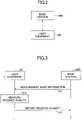
- Fig. 3 is a sequence diagram illustrating an example of processing sequence which is performed by the radio communication system according to the embodiment.
- a base station eNB transmits measurement band information (hereinafter referred to as "measurement band information") indicating a frequency range in which received quality is measured to a user equipment UE.
- the base station eNB may transmit the measurement band information to the user equipment UE using an RRC message.
- the base station eNB may transmit (broadcast) the measurement band information using broadcast information.
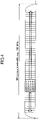
- a setting example of the measurement band information is illustrated in Fig. 4 .
- an arbitrary frequency range can be set in the measurement band information.
- the frequency range may be expressed using indices of RBs. For example, when indices (for example, RB#0 to RB#100 in the ascending order) are allocated to the RBs over the entire system band in advance, the frequency range may be expressed, for example, by RB#10 to RB#20.
- the frequency range may be set in any way, but it is preferable that the frequency range be set to frequencies (frequencies at which the problem described with reference to Fig. 1 does not occur) at which an interference of an adjacent cell can be appropriately measured. In order to suppress power consumption of the user equipment UE, it is preferable that a width of the frequency range (a measurement band) be set to a certain narrow bandwidth.
- Step S12 the user equipment UE measures received quality of a cell in the frequency range indicated by the measurement band information received from the base station eNB.
- the received quality may be RSRQ, RSRP, RSSI, or SINR and may include a part or all thereof.
- the measurement of the received quality may be performed using any method, but the user equipment UE may measure the received quality, for example, using any one of a reference signal or a synchronization signal which is mapped on the frequency range indicated by the measurement band information.
- the reference signal may be a reference signal specific to the user equipment UE or may be a reference signal specific to the cell.
- the synchronization signal may be a synchronization signal (SS) specific to the user equipment UE or may be a synchronization signal specific to the cell.
- SS synchronization signal
- the user equipment UE may switch the received quality measuring method in the RRC connected state and the RRC idle state. For example, the user equipment UE may measure the received quality using the reference signal specific to the user equipment UE or the synchronization signal specific to the user equipment UE when it is in the RRC connected state, and may measure the received quality using the reference signal specific to the cell or the synchronization signal specific to the cell when it is in the RRC idle state.
- Step S13 the user equipment UE reports the measurement result of the received quality to the base station eNB.
- the measurement band can be set in consideration of the interference of an adjacent cell. Even when the system bandwidth is wide, it is possible to suppress the measurement band and to suppress the power consumption of the user equipment UE based on the measurement of the received quality.
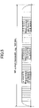
- plural frequency ranges may be set in the measurement band information which is transmitted from the base station eNB to the user equipment UE in the processing sequence of Step S11.
- the user equipment UE measures the received quality for each of the plural frequency ranges.
- the user equipment UE may report the measured received qualities to the base station eNB or may report an average value of the measured received qualities to the base station eNB. In the example illustrated in Fig.
- the user equipment UE may transmit capability information (for example, UE Capability Information) indicating whether the user equipment UE has capability of receiving the measurement band information in which plural frequency ranges are set and measuring the received quality to the base station eNB. Accordingly, only when the user equipment UE has the capability, the base station eNB can transmit the measurement band information in which plural frequency ranges are set to the user equipment UE.
- capability information for example, UE Capability Information
- Step S12 in order to cause the user equipment UE in the RRC idle state to measure the received quality using the synchronization signal (the synchronization signal specific to the cell) and/or the reference signal (the reference signal specific to the cell), the base station eNB needs to the synchronization signal and/or the reference signal in advance in the measurement band indicated by the measurement band information.
- the synchronization signal is fixedly defined to be transmitted using six RB at the center of the system band. Accordingly, in order to embody the invention, a structure for causing the base station eNB to transmit the synchronization signal and the reference signal, which are used to measure the quality, in an arbitrary band in the system band is required.
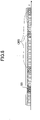
- the base station eNB transmits the synchronization signal in an arbitrary band in the system band and transmits broadcast information (Master Information Block (MIB)) including the center frequency of a carrier and/or the system bandwidth in the same band as the synchronization signal or a band separated by a predetermined offset from the synchronization signal.
- the predetermined offset may be defined in advance in a standard specification.
- a corresponding relationship between a signal sequence of the synchronization signal and the offset value may be defined in advance in a standard specification and the user equipment UE may recognize the offset value from the signal sequence of the received synchronization signal.
- the base station eNB may include information indicating the system bandwidth in an MIB which is transmitted using a physical broadcast channel (PBCH) and transmit the MIB, and may include information indicating the center frequency of the carrier in a system information block (SIB) (for example SIB1) which is transmitted using a physical downlink shared channel (PDSCH) and transmit the SIB.
- SIB system information block
- the base station eNB may include the information indicating the center frequency of the carrier in an MIB and transmit the MIB, and may include the information indicating the system bandwidth in an SIB (for example, SIB1) and transmit the SIB.
- the base station eNB may include the information indicating the system bandwidth and the information indicating the center frequency of the carrier in an MIB and transmit the MIB.
- the base station eNB may transmit the synchronization signal using six PRB similarly to the conventional LTE, but is not limited thereto and may transmit a bandwidth other than the six PRB.
- the user equipment UE can recognize the center frequency of the carrier and the system bandwidth by receiving broadcast information after detecting the synchronization signal by cell search.
- the user equipment UE can recognize at what position the synchronization signal is present in the system band.
- the base station eNB may time-multiplex the reference signal (for example, a cell specific reference signal (CRS)), which is used to measure the received quality by the user equipment UE, in the same band as the synchronization signal.
- Fig. 7A illustrates a state in which a synchronization signal and a reference signal are time-multiplexed and transmitted in the same band.
- Fig. 7B illustrates an example of resource mapping when a synchronization signal and a reference signal are time-multiplexed.
- a symbol (or a resource element) in which a reference signal is transmitted in a slot in which the synchronization signal is transmitted may be defined in advance in a standard specification or may be uniquely determined on the basis of the sequence of the synchronization signal.
- the base station eNB may transmit the reference signal, which is used to measure a received quality by the user equipment UE, in a band different from that of the synchronization signal.
- Fig. 8 illustrates a state in which a synchronization signal and three reference signals are transmitted in different bands.
- the base station eNB may include information indicating the bands (frequency resources) in which the reference signals are transmitted in the MIB and transmit the MIB or may include the information in the SIB (for example, SIB1) and transmit the SIB.
- a symbol (or a resource element) in which the reference signal is transmitted may be defined in advance in a standard specification or may be uniquely determined on the basis of the sequence of the synchronization signal. Accordingly, the user equipment UE can recognize the resource in which the reference signal used to measure the received quality is transmitted by receiving broadcast information after detecting the synchronization signal by cell search.
- the base station eNB may additionally include the information indicating the bands (frequency resources) in which the reference signals are transmitted in a cell as a reselection destination in a specific SIB (for example, SIB3 and SIB5) and transmit the specific SIB.
- a symbol (or a resource element) in which a reference signal is transmitted in the cell as the reselection destination may be defined in advance in a standard specification or may be uniquely determined on the basis of the sequence of the synchronization signal.
- the user equipment UE can recognize the resource in which the reference signal to be used to measure the received quality is transmitted in the cell as a reselection destination by receiving the information using the specific SIB.
- a frequency band for example, equal to or higher than 6 GHz
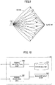
- the coverage is generally narrowed. Therefore, in the 3GPP, a technique called beam sweeping in which the coverage is secured in the entire areas of 360 degrees by transmitting plural narrow beams in the cell and sequentially switching the beam direction with the lapse of time has been proposed.
- a signal is transmitted by plural narrow beams rightward from the base station.
- the base station transmits the signal at the entire areas of 360 degrees by sequentially switching the transmission direction of the plural narrow beams to upward, leftward, and downward with the lapse of time.
- the time interval in which the beam transmission direction is switched it has been proposed that the beam transmission direction is switched such that the signal is transmitted in the entire areas of 360 degrees within one sub-frame (1 ms in the LTE).
- the user equipment UE in the standby state performs cell selection or cell reselection with its own state transition.
- the cell selection selects a cell having the highest received quality (the strongest cell) among cells satisfying a cell selection criterion (cell selection criterion S) out of cells which have been discovered by scanning a predetermined frequency.
- the cell selection criterion is defined by Expression 1 in 3GPP specifications (Non-Patent Document 1).
- Srxlev which is used in Expression 1 is defined by Equation 2 and Squal is defined by Expression 3.
- Srxlev is a value of a received level (an RX level value).
- Squal is a value of a received quality (a quality value).
- Q rxlevmeas is a value of a received level (RSRP) in a measured cell.
- Q qualmeas is a value of a received quality (RSRQ) in a measured cell.
- Q rxlevmin is a minimum value of a requested received level.
- Q qualmin is a minimum value of a requested received level.
- Q rxlevminoffset , Q qualminoffset , and Q offsettemp are predetermined offset values.
- P compensation is a compensated value of uplink transmitting power of the user equipment UE.
- the cell reselection is to rank a cell satisfying the above-mentioned cell selection criterion (the cell selection criterion S) among the cell discovered by scanning a predetermined frequency using a cell ranking criterion (a cell ranking criterion R) and to select a cell having a highest rank (a best cell).
- the cell ranking criterion is defined by Expressions 4 and 5 in the 3GPP specifications (Non-Patent Document 1). Expression 4 is applied to a serving cell and Expression 5 is applied to an adjacent cell.
- R s Q meas , s + Q Hyst ⁇ Q offsettemp
- R n Q meas , n ⁇ Q offset ⁇ Q offsettemp
- Qmeas is a value of an RSRP. More specifically, Qmeas,s is an RSRP value of a serving cell, and Q meas,n is an RSRP value of an adjacent cell.
- Q Hyst and Qoffsettemp are predetermined offset values.
- plural beams are transmitted from the same base station eNB.
- the base station eNB transmits a synchronization signal (a cell specific synchronization signal) and a reference signal (a cell specific reference signal) using the same cell ID (PCI: Physical Cell ID) for the plural beams.
- PCI Physical Cell ID
- the base station eNB transmits the same information for the plural beams regarding the broadcast information (the MIB and the SIB).
- the MIB and the SIB the broadcast information
- the user equipment UE receiving plural beams will erroneously recognize that plural cells having the same cell ID are present.
- the user equipment UE may measure signals (synchronization signal or reference signal) which are transmitted in the plural beams and may consider a highest received quality (for example, RSRP/RSRQ/RS-SINR/other measurement indices) among the measured received qualities of the beams as the received quality of the cell to be measured.
- signals synchronization signal or reference signal
- a highest received quality for example, RSRP/RSRQ/RS-SINR/other measurement indices
- Qrxievmeas may be defined as a received level (RSRP) value of the beam having the highest received level (RSRP) in the measured cell (or among the beams having the same cell ID).
- Q qualmeas may be defined as a received quality (RSRQ) value of the beam having the highest received quality (RSRQ) in the measured cell (or among the beams having the same cell ID).
- Q meas may be defined as a received level (RSRP) value of the beam having the highest received level (RSRP) in the measured cell (or among the beams having the same cell ID).
- the user equipment UE may measure signals (synchronization signals or reference signals) which are transmitted in the plural beams in the cell to be measured and may consider an average value of the measured received qualities (for example, RSRP/RSRQ/RS-SINR/other measurement indices) of the beams as the received quality of the cell to be measured.
- signals synchronization signals or reference signals
- the measured received qualities for example, RSRP/RSRQ/RS-SINR/other measurement indices
- Qrxievmeas may be defined as an average value of the received levels (RSRP) of the beams in the measured cell (or among the beams having the same cell ID).
- Q qualmeas may be defined as an average value of the received qualities (RSRQ) of the beams in the measured cell (or among the beams having the same cell ID).
- Qmeas may be defined as an average value of the received levels (RSRP) of the beams in the measured cell (or among the beams having the same cell ID).
- the cell ID may be replaced with an evolved cell global identifier (ECGI).
- ECGI evolved cell global identifier
- RS-SINR or other measurement indices may be used instead of one or both of the RSRP and the RSRQ).
- a "beam” may be referred to as a "pre-coded signal” or may be referred to as a "signal transmitted from a specific antenna port.”
- An antenna port refers to a logical antenna port which is defined in the 3GPP.
- the specific antenna port may be an antenna port which is defined to perform beam sweeping.
- Fig. 10 is a diagram illustrating an example of a functional configuration of a user equipment according to the embodiment.
- the user equipment UE includes a signal transmitting unit 101, a signal receiving unit 102, a storage unit 103, and a measurement unit 104.
- Fig. 10 illustrates only functional units, which are particularly associated with the invention, in the user equipment UE, and the user equipment UE has at least a function, which is not illustrated, for performing operations based on the LTE (including the 5G).
- the signal transmitting unit 101 has a function of generating various signals of a physical layer from a signal of an upper layer to be transmitted from the user equipment UE and wirelessly transmitting the generated signals.
- the signal receiving unit 102 has a function of wirelessly receiving various signals from the base station eNB and acquiring a signal of an upper layer from the received signals of the physical layer.
- the signal receiving unit 102 receives measurement band information indicating a frequency range in which a received quality is measured in a system bandwidth from the base station eNB and stores the received measurement band information in the storage unit 103.
- the measurement band information may include plural frequency ranges.
- the signal receiving unit 102 may receive the measurement band information from the base station eNB using an RRC message in an RRC connected state and may receive the measurement band information from the base station eNB using broadcast information in an RRC idle state.
- the storage unit 103 has a function of storing the measurement band information received from the base station eNB.
- the measurement unit 104 has a function of measuring a received quality in the frequency range indicated by the measurement band information.
- the measurement unit 104 may measure the received quality using one of a reference signal and a synchronization signal which is mapped on the frequency range indicated by the measurement band information.
- the measurement unit 104 may consider a signal having the highest received quality among the signals having the same cell ID as the measured received quality.
- Fig. 11 is a diagram illustrating an example of a functional configuration of a base station according to the embodiment.
- the base station eNB includes a signal transmitting unit 201, a signal receiving unit 202, and a broadcast unit 203.
- Fig. 11 illustrates only functional units, which are particularly associated with the invention, in the base station eNB, and the base station eNB has at least a function, which is not illustrated, for performing operations based on the LTE (including the 5G).
- the signal transmitting unit 201 has a function of generating various signals of a physical layer from a signal of an upper layer to be transmitted from the base station eNB and wirelessly transmitting the generated signals.
- the signal receiving unit 202 has a function of receiving various radio signals from the user equipment UE and acquiring a signal of an upper layer from the received signals of the physical layer.
- the signal transmitting unit 201 has a function of transmitting a synchronization signal in the frequency range indicated by the measurement band information in a system bandwidth and transmitting an MIB including information indicating the system bandwidth and/or information indicating a center frequency of a carrier.
- the signal transmitting unit 201 may transmit the synchronization signal in the frequency range indicated by the measurement band information in the system band and may transmit the MIB including information indicating the system bandwidth and an SIB including information indicating the center frequency of the carrier.
- the signal transmitting unit 201 may transmit the synchronization signal in the frequency range indicated by the measurement band information in the system band and may transmit the MIB including information indicating the center frequency of the carrier and the SIB including information indicating the system bandwidth.
- the broadcast unit 203 has a function of broadcasting the measurement band information indicating the frequency range in which the user equipment UE measures the received quality in the system bandwidth to the user equipment UE.
- the block diagrams ( Figs. 10 and 11 ) which are used above to describe the embodiment illustrate blocks in the units of functions.
- the functional blocks (constituent units) are embodied in an arbitrary combination of hardware and/or software. Means for embodying the functional blocks is not particularly limited. That is, the functional blocks may be embodied by one unit which is physically and/or logically coupled or may be embodied by two or more units which are physically and/or logically separated and which are connected directly and/or indirectly (for example, in a wired and/or wireless manner).
- the user equipment UE and the base station eNB in the embodiment may function as computers that perform the processes of the measurement method according to the invention.
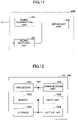
- Fig. 12 is a diagram illustrating an example of a hardware configuration of the user equipment and the base station according to the invention.
- the user equipment UE and the base station eNB may be physically configured as a computer device including a processor 1001, a memory 1002, a storage 1003, a communication unit 1004, an input unit 1005, an output unit 1006, and a bus 1007.
- a word "unit” may be referred to as a circuit, a device, a unit, or the like.
- the hardware configurations of the user equipment UE and the base station eNB may include one or more units illustrated in the drawing or may not include some units.
- the functions of the user equipment UE and the base station eNB are realized by causing hardware such as the processor 1001 and the memory 1002 to read predetermined software (a program) and causing the processor 1001 to perform computation and to control communication of the communication unit 1004 and reading and/or writing of data in the memory 1002 and the storage 1003.
- the processor 1001 controls the computer as a whole, for example, by operating an operating system.
- the processor 1001 may be constituted by a central processing unit (CPU) including an interface with peripherals, a control unit, a calculation unit, a register, and the like.
- CPU central processing unit
- the signal transmitting unit 101, the signal receiving unit 102, the storage unit 103, and the measurement unit 104 of the user equipment UE and the signal transmitting unit 201, the signal receiving unit 202, and the broadcast unit 203 of the base station eNB may be embodied by the processor 1001.
- the processor 1001 reads a program (program codes), a software module, or data from the storage 1003 and/or the communication unit 1004 to the memory 1002 and performs various processes in accordance therewith.
- a program causing a computer to perform at least a part of the operations described above in the embodiment is used.
- the signal transmitting unit 101, the signal receiving unit 102, the storage unit 103, and the measurement unit 104 of the user equipment UE and the signal transmitting unit 201, the signal receiving unit 202, and the broadcast unit 203 of the base station eNB may be embodied by a control program which is stored in the memory 1002 and operated by the processor 1001 or the other functional blocks may be similarly embodied.
- Various processes described above have been described to be performed by a single processor 1001, but may be simultaneously or sequentially performed by two or more processors 1001.
- the processor 1001 may be mounted as one or more chips.
- the program may be transmitted from a network via an electric communication line.
- the memory 1002 is a computer-readable recording medium and may be constituted, for example, by at least one of a read only memory (ROM), an erasable programmable ROM (EPROM), an electrically erasable programmable ROM (EEPROM), and a random access memory (RAM).
- the memory 1002 may be referred to as a register, a cache, or a main memory (a main storage unit).
- the memory 1002 can store a program (program codes), a software module, or the like which can be executed to perform the measurement method according to the embodiment.
- the storage 1003 is a computer-readable recording medium and may be constituted, for example, by at least one of an optical disc such as a compact disc ROM (CD-ROM), a hard disk drive, a flexible disk, a magneto-optical disk (such as a compact disk, a digital versatile disk, or a Blu-ray (registered trademark) disk), a smart card, a flash memory (such as a card, a stick, or a key drive), a floppy (registered trademark) disk, and a magnetic strip.
- the storage 1003 may be referred to as an auxiliary storage unit.
- Examples of the recording medium may include a database including the memory 1002 and/or the storage 1003, a server, and another appropriate medium.
- the communication unit 1004 is hardware (a transceiver device) that allows communication between computers via a wired and/or wireless network and is referred to as, for example, a network device, a network controller, a network card, or a communication module.
- a network device a network controller, a network card, or a communication module.
- the signal transmitting unit 101 and the signal receiving unit 102 of the user equipment UE and the signal transmitting unit 201 and the signal receiving unit 202 of the base station eNB may be embodied by the communication unit 1004.
- the input unit 1005 is an input device (such as a keyboard, a mouse, a microphone, a switch, a button, or a sensor) that receives an input from the outside.
- the output unit 1006 is an output device (such as a display, a speaker, or an LED lamp) that performs outputting to the outside.
- the input unit 1005 and the output unit 1006 may be configured as a unified body (such as a touch panel).
- the units such as the processor 1001 and the memory 1002 are connected to each other via the bus 1007 for transmitting and receiving information.
- the bus 1007 may be constituted by a single bus or may be configured by different buses for the units.
- the user equipment UE and the base station eNB may be configured to include hardware such as a microprocessor, a digital signal processor (DSP), an application specific integrated circuit (ASIC), a programmable logic device (PLD), or a field programmable gate array (FPGA) or a part or all of the functional blocks may be embodied by the hardware.
- the processor 1001 may be mounted as at least one hardware module.
- user equipment of a radio communication system including a base station and the user equipment, the user equipment including a receiver that receives, from the base station, measurement band information indicating a frequency range in which received quality is measured in a system bandwidth; and a measurer that measures the received quality in the frequency range indicated by the measurement band information.
- a received quality measuring method can be flexibly configured in the user equipment, and, thus, interference caused by an adjacent cell can be accurately measured for each cell.
- the measurement band information may include plural frequency ranges. Accordingly, even when the system band is wide and the interference of an adjacent cell varies depending on the frequency, it is possible to suppress power consumption of the user equipment UE and to appropriately measure the received quality.
- the receiver may receive the measurement band information from the base station using an RRC message in an RRC connected state and may receive the measurement band information from the base station using broadcast information in an RRC idle state. Accordingly, the user equipment UE can change the method of acquiring the measurement band information depending on the RRC state.
- the measurer may measure received quality using any one of a reference signal or a synchronization signal which are mapped on the frequency range indicated by the measurement band information. Accordingly, the user equipment UE can measure the received quality using the reference signal or the synchronization signal.
- the measurer may consider received quality of a signal having highest received quality among signals having the same cell ID as measured received quality when the signals transmitted from a plurality of specific antenna ports are received in the frequency range indicated by the measurement band information and the cell IDs included in the received signals are the same. Accordingly, the user equipment UE can appropriately measure the received quality even when beam sweeping is performed.
- a base station of a radio communication system including the base station and user equipment, the base station including a communicator that broadcasts, to the user equipment, measurement band information indicating a frequency range in which the user equipment measures received quality in a system bandwidth; and a transmitter that transmits a synchronization signal in the frequency range and that transmits a Master Information Block, MIB, including information indicating the system bandwidth or information indicating a center frequency of a carrier, wherein the transmitter transmits the MIB in the same frequency range as the frequency range or a frequency range deviated by a predetermined offset from the frequency range.
- MIB Master Information Block
- a measurement method which is performed by a user equipment of a radio communication system including a base station and the user equipment, the measurement method including: receiving, from the base station, measurement band information indicating a frequency range in which received quality is measured in a system bandwidth; and measuring the received quality in the frequency range indicated by the measurement band information.
- the base station eNB may be referred to as a NodeB (NB), a base station, a gNB, or several other appropriate terms by those skilled in the art.
- NB NodeB
- gNB gNodeB
- Transmission of the measurement band information is not limited to the aspect/embodiment described in this specification, and may be performed by other methods.
- transmission of the measurement band information may be performed by physical layer signaling (such as downlink control information (DCI) or uplink control information (UCI)), medium access control (MAC) signaling, other signaling, or a combination thereof.
- DCI downlink control information
- UCI uplink control information
- MAC medium access control
- RRC message may be referred to as RRC signaling.
- the RRC message includes an RRC connection setup message and an RRC connection reconfiguration message.
- LTE long term evolution
- LTE-A LTE-advanced
- SUPER 3G IMT-Advanced
- 4G 5G
- future radio access FAA
- W-CDMA registered trademark
- GSM registered trademark
- CDMA2000 ultra mobile broadband
- UMB ultra mobile broadband
- IEEE 802.11 Wi-Fi
- IEEE 802.16 WiMAX
- IEEE 802.20 ultra-wideband
- UWB ultra-wideband
- Bluetooth registered trademark
- Determination or decision may be made by a value (0 or 1) represented by one bit, may be made by a Boolean value (Boolean: true or false), and may be made by comparison of numerical values (comparison with a predetermined value, for example).
- the channel and/or symbol may be signaling (signal).
- a signal may be a message.
- the UE may be referred to, by a person ordinarily skilled in the art, as a subscriber station, a mobile unit, a subscriber unit, a wireless unit, a remote unit, a mobile device, a wireless device, a wireless communication device, a remote device, a mobile subscriber station, an access terminal, a mobile terminal, a wireless terminal, a remote terminal, a handset, a user agent, a mobile client, a client, or it may also be called by some other suitable terms.
- notification of predetermined information is not limited to notification that is made explicitly, and the notification may be made implicitly (e.g., notification of the predetermined information is not performed).
- determining and “deciding” used in this specification may include various types of operations. For example, “determining” and “deciding” may include deeming that a result of calculating, computing, processing, deriving, investigating, looking up (e.g., search in a table, a database, or another data structure), or ascertaining is determined or decided. Furthermore, “determining” and “deciding” may include, for example, deeming that a result of receiving (e.g., reception of information), transmitting (e.g., transmission of information), input, output, or accessing (e.g., accessing data in memory) is determined or decided. Furthermore, “determining” and “deciding” may include deeming that a result of resolving, selecting, choosing, establishing, or comparing is determined or decided. Namely, "determining” and “deciding” may include deeming that some operation is determined or decided.
- Input and output information and the like may be stored in a specific location (for example, a memory) and may be managed by a management table.
- the input and output information and the like may be overwritten, updated, or rewritten.
- the output information and the like may be erased.
- the input information and the like may be transmitted to other apparatuses.
- Notification of predetermined information is not limited to notification that is made explicitly, and the notification may be made implicitly (e.g., notification of the predetermined information is not performed).
- Information, signals, and the like described in the present specification may be represented using any of various other techniques.
- data, instructions, commands, information, signals, bits, symbols, chips, and the like mentioned in the entire description may be represented by voltage, current, electromagnetic waves, magnetic field or magnetic particles, optical field or photons, or any combination thereof.
Description
- The present invention relates to a user equipment, a system and a measurement method.
- In an LTE-based mobile communication system, a user equipment UE in an RRC idle state measures received qualities (Reference Signal Received Power (RSRP)/Reference Signal Received Quality (RSRQ)) of signals which are transmitted from a base station eNB of a serving cell and a base station eNB of an adjacent cell, and performs cell selection or cell reselection on the basis of the measurement result (for example, see Non-Patent Document 1).
- A user equipment UE in an RRC connected state measures received quality of signals which are transmitted from a base station eNB of a serving cell and a base station eNB of an adjacent cell and broadcasts the measurement result as a measurement report to the base stations eNB, and the base stations eNB control, for example, a handover on the basis of the measurement report (for example, see Non-Patent Document 2).
-
- Non-Patent Document 1: 3GPP TS 36.304 V12.4.0 (2015-03)
- Non-Patent Document 2: 3GPP TS36.331 V12.5.0 (2015-03) Document
US 2016/057708 A1 relates to relates to interference coordination techniques for scenarios where two neighboring base stations transmit on different carrier frequencies having bandwidths that overlap at least in part. - Document
US 2016/013984 A1 relates to a radio resource management information measurement method. - Document
WO 2013/116272 A1 relates to method for performing reference signal (RS) metric measurements in different parts of a channel bandwidth. -
Document EP 2 800 412 A1 relates to relates to method for enhancing measurement in a wireless communication system. - 3GPP document R2-165015 "Measurement in NR" by Intel Corporation studies RRM measurements in a NR system where NR cells comprise of one or more TRPs and each TRPs may form one or more beams.
- Similarly, 3GPP document R2-162226 "Discussion on Beam Measurement and Tracking for 5G New Radio Interface in mmWave Frequency Bands" by Samsung studies beam measurements in mmWave.
- 3GPP TR 36.897 "Study on elevation beamforming / Full-Dimension (FD) Multiple Input Multiple Output (MIMO) for LTE (Release 13)" Version 13.0.0 invenstiges aims to understand performance benefit of standard enhancements targeting two-dimensional antenna array operation.
- In the current 3GPP, a user equipment UE is prescribed to measure received quality (RSRP/RSRQ) using resources of a bandwidth of 6 resource blocks (RB) or 50 RB at the center of a system band. In general, a user equipment UE often measures received quality using resources of a bandwidth corresponding 6 RB in consideration of power consumption or the like.
- Here, when received quality is measured using the bandwidth corresponding to 6 RB, there is a case in which the received quality cannot be correctly measured. For example, as illustrated in
Fig. 1 , a scenario in which aserving cell 1 having a system bandwidth of 10 MHz (in which an actual transmission bandwidth is 9 MHz), anadjacent cell 2 having a system bandwidth of 5 MHz (in which an actual transmission bandwidth is 4.5 MHz) centered on a frequency separated by -2.5 MHz from the center frequency of theserving cell 1, and anadjacent cell 3 having a system bandwidth of 5 MHz (in which an actual transmission bandwidth is 4.5 MHz) centered on a frequency separated by +2.5 MHz from the center frequency of theserving cell 1 are present is assumed. In this scenario, a gap of 0.5 MHz (5 - (4.5 + 4.5)/2 = 0.5) is generated between the transmission bands of theadjacent cell 2 and theadjacent cell 3. Accordingly, when the received quality is measured using the bandwidth corresponding to 6 RB at the center of the system bandwidth in theserving cell 1, degrees of interference of theadjacent cell 2 and theadjacent cell 3 are not satisfactorily considered. - In order to solve this problem, in Release 11 of the LTE, a structure which is called wideband RSRQ measurement is defined. The wideband RSRQ measurement is a system in which the received quality is measured using the actual transmission bandwidth of the system bandwidth. However, since the received quality is measured using a large bandwidth, the power consumption of the user equipment using the wideband RSRQ measurement increases.
- In the 3GPP, fifth-generation (5G) radio technology has been studied to realize a further increase in capacity of the system capacity. Since there is a high possibility that radio technology other than the LTE will be employed in the 5G, a radio network supporting the 5G is referred to as a new radio access network (NewRAT) to distinguish it from the radio network supporting the LTE.
- In the 5G, it is assumed that a system bandwidth larger than the system bandwidth (20 MHz in maximum) of the LTE is supported. Accordingly, there is a problem in that power consumption of a user equipment further increases when the wideband RSRQ measurement is used. Accordingly, in the 5G, a structure that can solve the problem described above with reference to
Fig. 1 and suppress power consumption of a user equipment is necessary in measuring received quality. - A technique disclosed herein is made in consideration of the above-mentioned circumstances and an object thereof is to provide a technique enabling a received quality measuring method to be flexibly set in a user equipment so as to accurately measure interference of an adjacent cell for each cell.
- The present invention is defined by the appended independent claims. Advantageous embodiments are defined in the appended dependent claims. According to an aspect of the present invention, there is provided user equipment of a radio communication system including a base station and the user equipment, the user equipment including a receiver that receives, from the base station, measurement band information indicating a frequency range in which received quality is measured in a system bandwidth; and a measurer that measures the received quality in the frequency range indicated by the measurement band information.
- According to the disclosed technique, a received quality measuring method can be flexibly configured in user equipment, and, thus, interference caused by an adjacent cell can be accurately measured for each cell.
-
-
Fig. 1 is a diagram illustrating a problem; -
Fig. 2 is a diagram illustrating an example of a configuration of a radio communication system according to an embodiment; -
Fig. 3 is a sequence diagram illustrating an example of a processing sequence which is performed by the radio communication system according to the embodiment; -
Fig. 4 is a diagram illustrating an example of a configuration of measurement band information; -
Fig. 5 is a diagram illustrating an example of a configuration of the measurement band information; -
Fig. 6 is a diagram illustrating an example of arrangement of a synchronization signal; -
Fig. 7A is a diagram illustrating an example of arrangement (time multiplexing) of a synchronization signal and a reference signal; -
Fig. 7B is a diagram illustrating an example of arrangement (time multiplexing) of a synchronization signal and a reference signal; -
Fig. 8 is a diagram illustrating an example of arrangement (frequency multiplexing) of a synchronization signal and a reference signal; -
Fig. 9 is a diagram illustrating beam sweeping; -
Fig. 10 is a diagram illustrating an example of a functional configuration of a user equipment according to the embodiment; -
Fig. 11 is a diagram illustrating an example of a functional configuration of a base station according to the embodiment; and -
Fig. 12 is a diagram illustrating an example of a hardware configuration of a user equipment and a base station according to the embodiment. - Hereinafter, embodiments of the invention will be described with reference to the accompanying drawings. The embodiments described below are only examples and embodiments of the invention are not limited to the following embodiments. For example, a radio communication system according to the embodiments is assumed to be an LTE-based (including 5G) system, but the invention is not limited to the LTE (including 5G) and can be applied to another scheme. In the specification and the appended claims, "LTE" is used in a wide meaning including fifth-generation communication schemes corresponding to
Releases Releases -
Fig. 2 is a diagram illustrating an example of a configuration of a radio communication system according to an embodiment. As illustrated inFig. 2 , the radio communication system according to this embodiment includes a base station eNB and a user equipment UE. One base station eNB and one user equipment UE are illustrated inFig. 2 , but this is only an example and plural base stations and plural user equipments UE may be present. - The base station eNB and the user equipment UE may support both the LTE and the NewRAT (NR) of the 5G, may support only the NewRAT (NR) of the 5G, or may support only the LTE.
-
Fig. 3 is a sequence diagram illustrating an example of processing sequence which is performed by the radio communication system according to the embodiment. - In Step S11, a base station eNB transmits measurement band information (hereinafter referred to as "measurement band information") indicating a frequency range in which received quality is measured to a user equipment UE. When the user equipment UE is in the RRC connected state, the base station eNB may transmit the measurement band information to the user equipment UE using an RRC message. When the user equipment UE is in the RRC idle state, the base station eNB may transmit (broadcast) the measurement band information using broadcast information. A setting example of the measurement band information is illustrated in
Fig. 4 . As illustrated inFig. 4 , an arbitrary frequency range can be set in the measurement band information. The frequency range may be expressed using indices of RBs. For example, when indices (for example,RB# 0 toRB# 100 in the ascending order) are allocated to the RBs over the entire system band in advance, the frequency range may be expressed, for example, byRB# 10 to RB#20. - The frequency range may be set in any way, but it is preferable that the frequency range be set to frequencies (frequencies at which the problem described with reference to
Fig. 1 does not occur) at which an interference of an adjacent cell can be appropriately measured. In order to suppress power consumption of the user equipment UE, it is preferable that a width of the frequency range (a measurement band) be set to a certain narrow bandwidth. - In Step S12, the user equipment UE measures received quality of a cell in the frequency range indicated by the measurement band information received from the base station eNB. The received quality may be RSRQ, RSRP, RSSI, or SINR and may include a part or all thereof.
- The measurement of the received quality may be performed using any method, but the user equipment UE may measure the received quality, for example, using any one of a reference signal or a synchronization signal which is mapped on the frequency range indicated by the measurement band information. The reference signal may be a reference signal specific to the user equipment UE or may be a reference signal specific to the cell. Similarly, the synchronization signal may be a synchronization signal (SS) specific to the user equipment UE or may be a synchronization signal specific to the cell.
- The user equipment UE may switch the received quality measuring method in the RRC connected state and the RRC idle state. For example, the user equipment UE may measure the received quality using the reference signal specific to the user equipment UE or the synchronization signal specific to the user equipment UE when it is in the RRC connected state, and may measure the received quality using the reference signal specific to the cell or the synchronization signal specific to the cell when it is in the RRC idle state.
- In Step S13, the user equipment UE reports the measurement result of the received quality to the base station eNB.
- The processing sequence which is performed by the radio communication system according to the embodiment has been described hitherto. Through the above-mentioned processing sequence, the measurement band can be set in consideration of the interference of an adjacent cell. Even when the system bandwidth is wide, it is possible to suppress the measurement band and to suppress the power consumption of the user equipment UE based on the measurement of the received quality.
- As illustrated in
Fig. 5 , plural frequency ranges may be set in the measurement band information which is transmitted from the base station eNB to the user equipment UE in the processing sequence of Step S11. In this case, in the processing sequence of Step S12, the user equipment UE measures the received quality for each of the plural frequency ranges. In the processing sequence of Step S13, the user equipment UE may report the measured received qualities to the base station eNB or may report an average value of the measured received qualities to the base station eNB. In the example illustrated inFig. 5 , three frequency ranges ofsub-band # 1,sub-band # 2, andsub-band # 3, and the user equipment UE measures the received qualities ofsub-band # 1,sub-band # 2, andsub-band # 3 and reports the measured received qualities to the base station eNB. - Accordingly, even when the system bandwidth is wide and the interference of an adjacent cell varies depending on the frequency, it is possible to suppress the power consumption of the user equipment UE and to appropriately measure the received quality.
- At a timing such as an attachment timing, the user equipment UE may transmit capability information (for example, UE Capability Information) indicating whether the user equipment UE has capability of receiving the measurement band information in which plural frequency ranges are set and measuring the received quality to the base station eNB. Accordingly, only when the user equipment UE has the capability, the base station eNB can transmit the measurement band information in which plural frequency ranges are set to the user equipment UE.
- In Step S12, in order to cause the user equipment UE in the RRC idle state to measure the received quality using the synchronization signal (the synchronization signal specific to the cell) and/or the reference signal (the reference signal specific to the cell), the base station eNB needs to the synchronization signal and/or the reference signal in advance in the measurement band indicated by the measurement band information. However, in the conventional rule of the LTE, the synchronization signal is fixedly defined to be transmitted using six RB at the center of the system band. Accordingly, in order to embody the invention, a structure for causing the base station eNB to transmit the synchronization signal and the reference signal, which are used to measure the quality, in an arbitrary band in the system band is required.
- In this embodiment, as illustrated in
Fig. 6 , the base station eNB transmits the synchronization signal in an arbitrary band in the system band and transmits broadcast information (Master Information Block (MIB)) including the center frequency of a carrier and/or the system bandwidth in the same band as the synchronization signal or a band separated by a predetermined offset from the synchronization signal. The predetermined offset may be defined in advance in a standard specification. A corresponding relationship between a signal sequence of the synchronization signal and the offset value may be defined in advance in a standard specification and the user equipment UE may recognize the offset value from the signal sequence of the received synchronization signal. - More specifically, the base station eNB may include information indicating the system bandwidth in an MIB which is transmitted using a physical broadcast channel (PBCH) and transmit the MIB, and may include information indicating the center frequency of the carrier in a system information block (SIB) (for example SIB1) which is transmitted using a physical downlink shared channel (PDSCH) and transmit the SIB. Alternatively, the base station eNB may include the information indicating the center frequency of the carrier in an MIB and transmit the MIB, and may include the information indicating the system bandwidth in an SIB (for example, SIB1) and transmit the SIB. The base station eNB may include the information indicating the system bandwidth and the information indicating the center frequency of the carrier in an MIB and transmit the MIB. Information indicating positions of radio resources (a time resource and a frequency resource) in which the SIB is included in the MIB.
- The base station eNB may transmit the synchronization signal using six PRB similarly to the conventional LTE, but is not limited thereto and may transmit a bandwidth other than the six PRB.
- Accordingly, the user equipment UE can recognize the center frequency of the carrier and the system bandwidth by receiving broadcast information after detecting the synchronization signal by cell search. The user equipment UE can recognize at what position the synchronization signal is present in the system band.
- The base station eNB may time-multiplex the reference signal (for example, a cell specific reference signal (CRS)), which is used to measure the received quality by the user equipment UE, in the same band as the synchronization signal.
Fig. 7A illustrates a state in which a synchronization signal and a reference signal are time-multiplexed and transmitted in the same band.Fig. 7B illustrates an example of resource mapping when a synchronization signal and a reference signal are time-multiplexed. A symbol (or a resource element) in which a reference signal is transmitted in a slot in which the synchronization signal is transmitted may be defined in advance in a standard specification or may be uniquely determined on the basis of the sequence of the synchronization signal. - The base station eNB may transmit the reference signal, which is used to measure a received quality by the user equipment UE, in a band different from that of the synchronization signal.
Fig. 8 illustrates a state in which a synchronization signal and three reference signals are transmitted in different bands. The base station eNB may include information indicating the bands (frequency resources) in which the reference signals are transmitted in the MIB and transmit the MIB or may include the information in the SIB (for example, SIB1) and transmit the SIB. A symbol (or a resource element) in which the reference signal is transmitted may be defined in advance in a standard specification or may be uniquely determined on the basis of the sequence of the synchronization signal. Accordingly, the user equipment UE can recognize the resource in which the reference signal used to measure the received quality is transmitted by receiving broadcast information after detecting the synchronization signal by cell search. - In order to the user equipment UE performing cell reselection to recognize the resources in which the reference signals are transmitted, the base station eNB may additionally include the information indicating the bands (frequency resources) in which the reference signals are transmitted in a cell as a reselection destination in a specific SIB (for example, SIB3 and SIB5) and transmit the specific SIB. A symbol (or a resource element) in which a reference signal is transmitted in the cell as the reselection destination may be defined in advance in a standard specification or may be uniquely determined on the basis of the sequence of the synchronization signal. The user equipment UE can recognize the resource in which the reference signal to be used to measure the received quality is transmitted in the cell as a reselection destination by receiving the information using the specific SIB.
- In the 5G, it is assumed that a frequency band (for example, equal to or higher than 6 GHz) higher than the frequency which is used in the conventional LTE is used. When a high frequency band is used, the coverage is generally narrowed. Therefore, in the 3GPP, a technique called beam sweeping in which the coverage is secured in the entire areas of 360 degrees by transmitting plural narrow beams in the cell and sequentially switching the beam direction with the lapse of time has been proposed. In the example illustrated in
Fig. 9 , a signal is transmitted by plural narrow beams rightward from the base station. The base station transmits the signal at the entire areas of 360 degrees by sequentially switching the transmission direction of the plural narrow beams to upward, leftward, and downward with the lapse of time. Regarding the time interval in which the beam transmission direction is switched, it has been proposed that the beam transmission direction is switched such that the signal is transmitted in the entire areas of 360 degrees within one sub-frame (1 ms in the LTE). - Here, in the conventional LTE, the user equipment UE in the standby state (in the RRC idle mode) performs cell selection or cell reselection with its own state transition. The cell selection selects a cell having the highest received quality (the strongest cell) among cells satisfying a cell selection criterion (cell selection criterion S) out of cells which have been discovered by scanning a predetermined frequency. The cell selection criterion is defined by
Expression 1 in 3GPP specifications (Non-Patent Document 1). Srxlev which is used inExpression 1 is defined byEquation 2 and Squal is defined byExpression 3.


- Srxlev is a value of a received level (an RX level value). Squal is a value of a received quality (a quality value). Qrxlevmeas is a value of a received level (RSRP) in a measured cell. Qqualmeas is a value of a received quality (RSRQ) in a measured cell. Qrxlevmin is a minimum value of a requested received level. Qqualmin is a minimum value of a requested received level. Qrxlevminoffset, Qqualminoffset, and Qoffsettemp are predetermined offset values. Pcompensation is a compensated value of uplink transmitting power of the user equipment UE.
- The cell reselection is to rank a cell satisfying the above-mentioned cell selection criterion (the cell selection criterion S) among the cell discovered by scanning a predetermined frequency using a cell ranking criterion (a cell ranking criterion R) and to select a cell having a highest rank (a best cell). The cell ranking criterion is defined by
Expressions Expression 4 is applied to a serving cell andExpression 5 is applied to an adjacent cell.

- Qmeas is a value of an RSRP. More specifically, Qmeas,s is an RSRP value of a serving cell, and Qmeas,n is an RSRP value of an adjacent cell. QHyst and Qoffsettemp are predetermined offset values.
- When the above-mentioned beam sweeping is performed, plural beams are transmitted from the same base station eNB. Here, as illustrated in
Fig. 9 , it is assumed that the base station eNB transmits a synchronization signal (a cell specific synchronization signal) and a reference signal (a cell specific reference signal) using the same cell ID (PCI: Physical Cell ID) for the plural beams. It is also assumed that the base station eNB transmits the same information for the plural beams regarding the broadcast information (the MIB and the SIB). In this case, according to the conventional LTE structure, there is a possibility that the user equipment UE receiving plural beams will erroneously recognize that plural cells having the same cell ID are present. - Therefore, when plural beams having the same cell ID are received in a cell to be measured, the user equipment UE may measure signals (synchronization signal or reference signal) which are transmitted in the plural beams and may consider a highest received quality (for example, RSRP/RSRQ/RS-SINR/other measurement indices) among the measured received qualities of the beams as the received quality of the cell to be measured.
- In this case, in
Expressions Expressions - As another method, when plural beams having the same cell ID are received, the user equipment UE may measure signals (synchronization signals or reference signals) which are transmitted in the plural beams in the cell to be measured and may consider an average value of the measured received qualities (for example, RSRP/RSRQ/RS-SINR/other measurement indices) of the beams as the received quality of the cell to be measured.
- In this case, in
Expressions Expressions - In the above description, the cell ID may be replaced with an evolved cell global identifier (ECGI). In
Expressions 1 to 5, RS-SINR or other measurement indices may be used instead of one or both of the RSRP and the RSRQ). - In the above description, a "beam" may be referred to as a "pre-coded signal" or may be referred to as a "signal transmitted from a specific antenna port." An antenna port refers to a logical antenna port which is defined in the 3GPP. For example, the specific antenna port may be an antenna port which is defined to perform beam sweeping.
- According to the above-mentioned measurement method, it is possible to appropriately measure a received quality even when beam sweeping is performed.
- Hereinafter, an example of a functional configuration of a user equipment UE that performs an operation according to the embodiment of the invention will be described.
-
Fig. 10 is a diagram illustrating an example of a functional configuration of a user equipment according to the embodiment. As illustrated inFig. 10 , the user equipment UE includes asignal transmitting unit 101, asignal receiving unit 102, astorage unit 103, and ameasurement unit 104.Fig. 10 illustrates only functional units, which are particularly associated with the invention, in the user equipment UE, and the user equipment UE has at least a function, which is not illustrated, for performing operations based on the LTE (including the 5G). - The
signal transmitting unit 101 has a function of generating various signals of a physical layer from a signal of an upper layer to be transmitted from the user equipment UE and wirelessly transmitting the generated signals. Thesignal receiving unit 102 has a function of wirelessly receiving various signals from the base station eNB and acquiring a signal of an upper layer from the received signals of the physical layer. Thesignal receiving unit 102 receives measurement band information indicating a frequency range in which a received quality is measured in a system bandwidth from the base station eNB and stores the received measurement band information in thestorage unit 103. The measurement band information may include plural frequency ranges. Thesignal receiving unit 102 may receive the measurement band information from the base station eNB using an RRC message in an RRC connected state and may receive the measurement band information from the base station eNB using broadcast information in an RRC idle state. - The
storage unit 103 has a function of storing the measurement band information received from the base station eNB. - The
measurement unit 104 has a function of measuring a received quality in the frequency range indicated by the measurement band information. Themeasurement unit 104 may measure the received quality using one of a reference signal and a synchronization signal which is mapped on the frequency range indicated by the measurement band information. When signals transmitted using plural beams (specific antenna ports) are received in the frequency range indicated by the measurement band information and the cell IDs included in the received signals are the same, themeasurement unit 104 may consider a signal having the highest received quality among the signals having the same cell ID as the measured received quality. -
Fig. 11 is a diagram illustrating an example of a functional configuration of a base station according to the embodiment. As illustrated inFig. 11 , the base station eNB includes asignal transmitting unit 201, asignal receiving unit 202, and abroadcast unit 203.Fig. 11 illustrates only functional units, which are particularly associated with the invention, in the base station eNB, and the base station eNB has at least a function, which is not illustrated, for performing operations based on the LTE (including the 5G). - The
signal transmitting unit 201 has a function of generating various signals of a physical layer from a signal of an upper layer to be transmitted from the base station eNB and wirelessly transmitting the generated signals. Thesignal receiving unit 202 has a function of receiving various radio signals from the user equipment UE and acquiring a signal of an upper layer from the received signals of the physical layer. Thesignal transmitting unit 201 has a function of transmitting a synchronization signal in the frequency range indicated by the measurement band information in a system bandwidth and transmitting an MIB including information indicating the system bandwidth and/or information indicating a center frequency of a carrier. Thesignal transmitting unit 201 may transmit the synchronization signal in the frequency range indicated by the measurement band information in the system band and may transmit the MIB including information indicating the system bandwidth and an SIB including information indicating the center frequency of the carrier. Thesignal transmitting unit 201 may transmit the synchronization signal in the frequency range indicated by the measurement band information in the system band and may transmit the MIB including information indicating the center frequency of the carrier and the SIB including information indicating the system bandwidth. - The
broadcast unit 203 has a function of broadcasting the measurement band information indicating the frequency range in which the user equipment UE measures the received quality in the system bandwidth to the user equipment UE. - The block diagrams (
Figs. 10 and11 ) which are used above to describe the embodiment illustrate blocks in the units of functions. The functional blocks (constituent units) are embodied in an arbitrary combination of hardware and/or software. Means for embodying the functional blocks is not particularly limited. That is, the functional blocks may be embodied by one unit which is physically and/or logically coupled or may be embodied by two or more units which are physically and/or logically separated and which are connected directly and/or indirectly (for example, in a wired and/or wireless manner). - For example, the user equipment UE and the base station eNB in the embodiment may function as computers that perform the processes of the measurement method according to the invention.
Fig. 12 is a diagram illustrating an example of a hardware configuration of the user equipment and the base station according to the invention. The user equipment UE and the base station eNB may be physically configured as a computer device including aprocessor 1001, amemory 1002, astorage 1003, acommunication unit 1004, aninput unit 1005, anoutput unit 1006, and abus 1007. - In the following description, a word "unit" may be referred to as a circuit, a device, a unit, or the like. The hardware configurations of the user equipment UE and the base station eNB may include one or more units illustrated in the drawing or may not include some units.
- The functions of the user equipment UE and the base station eNB are realized by causing hardware such as the
processor 1001 and thememory 1002 to read predetermined software (a program) and causing theprocessor 1001 to perform computation and to control communication of thecommunication unit 1004 and reading and/or writing of data in thememory 1002 and thestorage 1003. - The
processor 1001 controls the computer as a whole, for example, by operating an operating system. Theprocessor 1001 may be constituted by a central processing unit (CPU) including an interface with peripherals, a control unit, a calculation unit, a register, and the like. For example, thesignal transmitting unit 101, thesignal receiving unit 102, thestorage unit 103, and themeasurement unit 104 of the user equipment UE and thesignal transmitting unit 201, thesignal receiving unit 202, and thebroadcast unit 203 of the base station eNB may be embodied by theprocessor 1001. - The
processor 1001 reads a program (program codes), a software module, or data from thestorage 1003 and/or thecommunication unit 1004 to thememory 1002 and performs various processes in accordance therewith. As the program, a program causing a computer to perform at least a part of the operations described above in the embodiment is used. For example, thesignal transmitting unit 101, thesignal receiving unit 102, thestorage unit 103, and themeasurement unit 104 of the user equipment UE and thesignal transmitting unit 201, thesignal receiving unit 202, and thebroadcast unit 203 of the base station eNB may be embodied by a control program which is stored in thememory 1002 and operated by theprocessor 1001 or the other functional blocks may be similarly embodied. Various processes described above have been described to be performed by asingle processor 1001, but may be simultaneously or sequentially performed by two ormore processors 1001. Theprocessor 1001 may be mounted as one or more chips. The program may be transmitted from a network via an electric communication line. - The
memory 1002 is a computer-readable recording medium and may be constituted, for example, by at least one of a read only memory (ROM), an erasable programmable ROM (EPROM), an electrically erasable programmable ROM (EEPROM), and a random access memory (RAM). Thememory 1002 may be referred to as a register, a cache, or a main memory (a main storage unit). Thememory 1002 can store a program (program codes), a software module, or the like which can be executed to perform the measurement method according to the embodiment. - The
storage 1003 is a computer-readable recording medium and may be constituted, for example, by at least one of an optical disc such as a compact disc ROM (CD-ROM), a hard disk drive, a flexible disk, a magneto-optical disk (such as a compact disk, a digital versatile disk, or a Blu-ray (registered trademark) disk), a smart card, a flash memory (such as a card, a stick, or a key drive), a floppy (registered trademark) disk, and a magnetic strip. Thestorage 1003 may be referred to as an auxiliary storage unit. Examples of the recording medium may include a database including thememory 1002 and/or thestorage 1003, a server, and another appropriate medium. - The
communication unit 1004 is hardware (a transceiver device) that allows communication between computers via a wired and/or wireless network and is referred to as, for example, a network device, a network controller, a network card, or a communication module. For example, thesignal transmitting unit 101 and thesignal receiving unit 102 of the user equipment UE and thesignal transmitting unit 201 and thesignal receiving unit 202 of the base station eNB may be embodied by thecommunication unit 1004. - The
input unit 1005 is an input device (such as a keyboard, a mouse, a microphone, a switch, a button, or a sensor) that receives an input from the outside. Theoutput unit 1006 is an output device (such as a display, a speaker, or an LED lamp) that performs outputting to the outside. Theinput unit 1005 and theoutput unit 1006 may be configured as a unified body (such as a touch panel). - The units such as the
processor 1001 and thememory 1002 are connected to each other via thebus 1007 for transmitting and receiving information. Thebus 1007 may be constituted by a single bus or may be configured by different buses for the units. - The user equipment UE and the base station eNB may be configured to include hardware such as a microprocessor, a digital signal processor (DSP), an application specific integrated circuit (ASIC), a programmable logic device (PLD), or a field programmable gate array (FPGA) or a part or all of the functional blocks may be embodied by the hardware. For example, the
processor 1001 may be mounted as at least one hardware module. - According to the above-described embodiment, there is provided user equipment of a radio communication system including a base station and the user equipment, the user equipment including a receiver that receives, from the base station, measurement band information indicating a frequency range in which received quality is measured in a system bandwidth; and a measurer that measures the received quality in the frequency range indicated by the measurement band information. With this user equipment UE, a received quality measuring method can be flexibly configured in the user equipment, and, thus, interference caused by an adjacent cell can be accurately measured for each cell.
- The measurement band information may include plural frequency ranges. Accordingly, even when the system band is wide and the interference of an adjacent cell varies depending on the frequency, it is possible to suppress power consumption of the user equipment UE and to appropriately measure the received quality.
- The receiver may receive the measurement band information from the base station using an RRC message in an RRC connected state and may receive the measurement band information from the base station using broadcast information in an RRC idle state. Accordingly, the user equipment UE can change the method of acquiring the measurement band information depending on the RRC state.
- The measurer may measure received quality using any one of a reference signal or a synchronization signal which are mapped on the frequency range indicated by the measurement band information. Accordingly, the user equipment UE can measure the received quality using the reference signal or the synchronization signal.
- The measurer may consider received quality of a signal having highest received quality among signals having the same cell ID as measured received quality when the signals transmitted from a plurality of specific antenna ports are received in the frequency range indicated by the measurement band information and the cell IDs included in the received signals are the same. Accordingly, the user equipment UE can appropriately measure the received quality even when beam sweeping is performed.
- According to the embodiment, there is provided a base station of a radio communication system including the base station and user equipment, the base station including a communicator that broadcasts, to the user equipment, measurement band information indicating a frequency range in which the user equipment measures received quality in a system bandwidth; and a transmitter that transmits a synchronization signal in the frequency range and that transmits a Master Information Block, MIB, including information indicating the system bandwidth or information indicating a center frequency of a carrier, wherein the transmitter transmits the MIB in the same frequency range as the frequency range or a frequency range deviated by a predetermined offset from the frequency range. With this base station eNB, a received quality measuring method can be flexibly configured in the user equipment, and, thus, interference caused by an adjacent cell can be accurately measured for each cell.
- According to the embodiment, there is provided a measurement method which is performed by a user equipment of a radio communication system including a base station and the user equipment, the measurement method including: receiving, from the base station, measurement band information indicating a frequency range in which received quality is measured in a system bandwidth; and measuring the received quality in the frequency range indicated by the measurement band information. With this measurement method, a received quality measuring method can be flexibly configured in the user equipment, and, thus, interference caused by an adjacent cell can be accurately measured for each cell.
- The base station eNB may be referred to as a NodeB (NB), a base station, a gNB, or several other appropriate terms by those skilled in the art.
- Transmission of the measurement band information is not limited to the aspect/embodiment described in this specification, and may be performed by other methods. For example, transmission of the measurement band information may be performed by physical layer signaling (such as downlink control information (DCI) or uplink control information (UCI)), medium access control (MAC) signaling, other signaling, or a combination thereof. Examples of the RRC message may be referred to as RRC signaling. The RRC message includes an RRC connection setup message and an RRC connection reconfiguration message.
- The embodiment described in this specification may be applied to a system employing long term evolution (LTE), LTE-advanced (LTE-A), SUPER 3G, IMT-Advanced, 4G, 5G, future radio access (FRA), W-CDMA (registered trademark), GSM (registered trademark), CDMA2000, ultra mobile broadband (UMB), IEEE 802.11 (Wi-Fi), IEEE 802.16 (WiMAX), IEEE 802.20, ultra-wideband (UWB), Bluetooth (registered trademark), or other appropriate systems and/or a next-generation system which is extended on the basis thereof.
- Determination or decision may be made by a value (0 or 1) represented by one bit, may be made by a Boolean value (Boolean: true or false), and may be made by comparison of numerical values (comparison with a predetermined value, for example).
- Note that the terms described in this specification and/or the terms necessary for understanding of this specification may be replaced with terms having the same or similar meaning. For example, the channel and/or symbol may be signaling (signal). Furthermore, a signal may be a message.
- The UE may be referred to, by a person ordinarily skilled in the art, as a subscriber station, a mobile unit, a subscriber unit, a wireless unit, a remote unit, a mobile device, a wireless device, a wireless communication device, a remote device, a mobile subscriber station, an access terminal, a mobile terminal, a wireless terminal, a remote terminal, a handset, a user agent, a mobile client, a client, or it may also be called by some other suitable terms.
- Each aspect/embodiment described in this specification may be used alone, may be used in combination, or may be used while being switched during the execution. Furthermore, notification of predetermined information (e.g., notification of "being X") is not limited to notification that is made explicitly, and the notification may be made implicitly (e.g., notification of the predetermined information is not performed).
- The terms "determining" and "deciding" used in this specification may include various types of operations. For example, "determining" and "deciding" may include deeming that a result of calculating, computing, processing, deriving, investigating, looking up (e.g., search in a table, a database, or another data structure), or ascertaining is determined or decided. Furthermore, "determining" and "deciding" may include, for example, deeming that a result of receiving (e.g., reception of information), transmitting (e.g., transmission of information), input, output, or accessing (e.g., accessing data in memory) is determined or decided. Furthermore, "determining" and "deciding" may include deeming that a result of resolving, selecting, choosing, establishing, or comparing is determined or decided. Namely, "determining" and "deciding" may include deeming that some operation is determined or decided.
- The expression "on the basis of" used in the present specification does not mean "on the basis of only" unless otherwise stated particularly. In other words, the expression "on the basis of" means both "on the basis of only" and "on the basis of at least."
- Input and output information and the like may be stored in a specific location (for example, a memory) and may be managed by a management table. The input and output information and the like may be overwritten, updated, or rewritten. The output information and the like may be erased. The input information and the like may be transmitted to other apparatuses.
- Notification of predetermined information (e.g., notification of "being X") is not limited to notification that is made explicitly, and the notification may be made implicitly (e.g., notification of the predetermined information is not performed).
- Information, signals, and the like described in the present specification may be represented using any of various other techniques. For example, data, instructions, commands, information, signals, bits, symbols, chips, and the like mentioned in the entire description may be represented by voltage, current, electromagnetic waves, magnetic field or magnetic particles, optical field or photons, or any combination thereof.
- While the invention has been described above in detail, it is apparent to those skilled in the art that the invention is not limited to the embodiment described in the specification. The invention is defined by the appended claims. Accordingly, description in this specification is made for illustrative description and does not have any restrictive meaning.
-
- UE
- user equipment
- eNB
- base station
- 101
- signal transmitting unit
- 102
- signal receiving unit
- 103
- storage unit
- 104
- measurement unit
- 201
- signal transmitting unit
- 202
- signal receiving unit
- 203
- broadcast unit
- 1001
- processor
- 1002
- memory
- 1003
- storage
- 1004
- communication unit
- 1005
- input unit
- 1006
- output unit
Claims (5)
- A terminal comprising:a receiver (102) configured to receive (S11), from a base station, measurement band information indicating a frequency range in which received quality is to be measured; anda measurer (104) configured to measure (S12) a received quality of a cell of the base station in the frequency range indicated by the measurement band information,wherein the measurer (102) is configured to measure the received quality using a synchronization signal received from the base station on the frequency range indicated by the measurement band information,characterized in thatwhen synchronization signals transmitted from a plurality of specific logical antenna ports of the base station are received in the frequency range indicated by the measurement band information, the measurer (102) is configured to measure (S12) the received quality of the cell based on a signal with the highest received quality, among the signals with the identical cell IDs.
- The terminal according to claim 1, wherein the measurement band information includes a plurality of frequency ranges.
- The terminal according to claim 1 or 2, wherein the receiver (102) is configured to receive the measurement band information from the base station through an RRC message in an RRC connected state and receives the measurement band information from the base station through broadcast information in an RRC idle state.
- A measurement method which is performed by a terminal, the measurement method comprising:receiving (S11), from a base station, measurement band information indicating a frequency band range in which received quality is to be measured; andmeasuring (S12) a received quality of a cell of the base station in the frequency range indicated by the measurement band information,wherein that the measuring measures the received quality using a synchronization signal received from the base station on the frequency range indicated by the measurement band information,characterized in thatwhen synchronization signals transmitted from a plurality of specific logical antenna ports of the base station are received in the frequency range indicated by the measurement band information, the measuring (S12) determines the received quality of the cell based on a signal with the highest received quality, among the signals with the identical cell ID.
- A radio communication system comprising:a base station; anda terminal,wherein the base station includesa broadcast unit (203) configured to transmit, to the terminal, measurement bandinformation indicating a frequency range in which received quality is to be measured by the terminal,a signal transmitting unit (201) configured to transmit, to the terminal, a synchronization signal in the frequency range indicated by the measurement band information in the system bandwidth and an MIB including information indicating the system bandwidth or information indicating a center frequency of a carrier; anda signal receiving unit (202) configured to receive various radio signals from the terminal and acquire a signal of an upper layer from the received signals of the physical layer;wherein the signal transmitting unit (201) is configured to transmit said synchronization signal and a reference signal using the same physical cell ID, PCI, for a plurality of beams using a specific antenna port;wherein the terminal includesa receiver (102) configured to receive, from the base station, the measurement band information indicating a frequency range in which the received quality is to be measured; anda measurer (104) configured to measure a received quality of a cell of the base station in the frequency range indicated by the measurement band information,characterized in that the measurer (102) is configured to measure the received quality using a synchronization signal received from the base station on the frequency range indicated by the measurement band information, andwherein, when synchronization signals transmitted from a plurality of specific logical antenna ports of the base station are received in the frequency range indicated by the measurement band information, the measurer (102) is configured to determine the received quality of the cell based on a signal with the highest received quality, among the signals with the identical cell IDs.
Priority Applications (1)
| Application Number | Priority Date | Filing Date | Title |
|---|---|---|---|
| EP22195816.8A EP4125288A1 (en) | 2016-05-12 | 2017-03-31 | User equipment , base station, and measurement method |
Applications Claiming Priority (3)
| Application Number | Priority Date | Filing Date | Title |
|---|---|---|---|
| JP2016096524 | 2016-05-12 | ||
| JP2016192351 | 2016-09-29 | ||
| PCT/JP2017/013534 WO2017195494A1 (en) | 2016-05-12 | 2017-03-31 | User device, base station, and measurement method |
Related Child Applications (2)
| Application Number | Title | Priority Date | Filing Date |
|---|---|---|---|
| EP22195816.8A Division EP4125288A1 (en) | 2016-05-12 | 2017-03-31 | User equipment , base station, and measurement method |
| EP22195816.8A Division-Into EP4125288A1 (en) | 2016-05-12 | 2017-03-31 | User equipment , base station, and measurement method |
Publications (3)
| Publication Number | Publication Date |
|---|---|
| EP3457737A1 EP3457737A1 (en) | 2019-03-20 |
| EP3457737A4 EP3457737A4 (en) | 2020-02-19 |
| EP3457737B1 true EP3457737B1 (en) | 2022-11-02 |
Family
ID=60267147
Family Applications (2)
| Application Number | Title | Priority Date | Filing Date |
|---|---|---|---|
| EP22195816.8A Pending EP4125288A1 (en) | 2016-05-12 | 2017-03-31 | User equipment , base station, and measurement method |
| EP17795855.0A Active EP3457737B1 (en) | 2016-05-12 | 2017-03-31 | User device, base station, and measurement method |
Family Applications Before (1)
| Application Number | Title | Priority Date | Filing Date |
|---|---|---|---|
| EP22195816.8A Pending EP4125288A1 (en) | 2016-05-12 | 2017-03-31 | User equipment , base station, and measurement method |
Country Status (11)
| Country | Link |
|---|---|
| US (1) | US10772000B2 (en) |
| EP (2) | EP4125288A1 (en) |
| JP (2) | JP6937295B2 (en) |
| KR (1) | KR102360183B1 (en) |
| CN (1) | CN109155929A (en) |
| BR (1) | BR112018073160A2 (en) |
| CA (1) | CA3023353C (en) |
| ES (1) | ES2931469T3 (en) |
| IL (1) | IL262736B (en) |
| PT (1) | PT3457737T (en) |
| WO (1) | WO2017195494A1 (en) |
Families Citing this family (7)
| Publication number | Priority date | Publication date | Assignee | Title |
|---|---|---|---|---|
| CN108810931A (en) * | 2017-05-05 | 2018-11-13 | 华为技术有限公司 | Measurement method, terminal device and access network equipment |
| CN110603737B (en) * | 2017-06-02 | 2022-04-01 | 苹果公司 | Beamforming measurements for New Radios (NR) |
| US10681583B2 (en) | 2017-12-14 | 2020-06-09 | Qualcomm Incorporated | Cell quality measurement reporting for cells with mismatched beam numbers |
| EP3742625A4 (en) * | 2018-02-26 | 2021-04-21 | Mitsubishi Electric Corporation | Base station and radio communication method |
| CN110519793B (en) | 2018-05-22 | 2021-10-22 | 维沃移动通信有限公司 | Measurement reporting method, measurement configuration method, terminal and network side equipment |
| CN113784398B (en) * | 2020-06-09 | 2023-03-14 | 维沃移动通信有限公司 | Data processing method and device, terminal and network side equipment |
| US20220295316A1 (en) * | 2021-03-10 | 2022-09-15 | Sierra Wireless, Inc. | Method and apparatus for managing communication characteristics in a wireless network |
Family Cites Families (25)
| Publication number | Priority date | Publication date | Assignee | Title |
|---|---|---|---|---|
| US9489821B2 (en) * | 2010-02-04 | 2016-11-08 | Google Inc. | Device and method for monitoring the presence of an item |
| KR20120009913A (en) * | 2010-07-22 | 2012-02-02 | 엘지에릭슨 주식회사 | Apparatus and method for searching neighbor cells of femto cell and mobile telecommunication system for the same |
| CN102088423B (en) * | 2010-12-14 | 2013-12-25 | 北京邮电大学 | Method and device for measuring reference signal receiving power of time division duplex system |
| CN109890054B (en) * | 2012-01-21 | 2023-12-15 | 华为技术有限公司 | Method and apparatus for measurement enhancement in a wireless communication system |
| US10972920B2 (en) | 2012-01-30 | 2021-04-06 | Qualcomm Incorporated | Flexible radio resource management (RRM) measurements for wireless networks |
| US9491651B2 (en) * | 2012-10-01 | 2016-11-08 | Telefonaktiebolaget Lm Ericsson (Publ) | Adjusting measurement requirements for parallel uplink wireless signal measurements |
| US9503216B2 (en) * | 2012-11-02 | 2016-11-22 | Telefonaktiebolaget L M Ericsson (Publ) | Methods and devices related to effective measurements |
| US10021584B2 (en) | 2012-11-19 | 2018-07-10 | Lg Electronics Inc. | Reporting bandwidth measurements by a wireless device for cell reselection |
| CN104247492B (en) * | 2013-03-27 | 2020-08-07 | 华为技术有限公司 | Method, device and equipment for measuring radio resource management information |
| EP2984884A1 (en) * | 2013-04-08 | 2016-02-17 | Telefonaktiebolaget LM Ericsson (publ) | Performing inter-frequency measurements on carriers with overlapping bandwidths |
| US9934119B2 (en) * | 2013-10-22 | 2018-04-03 | Cisco Technology, Inc. | Rogue hardware detection through power monitoring |
| CN105009640B (en) * | 2013-12-30 | 2020-02-14 | 华为技术有限公司 | Channel measurement method, cell switching method, related device and system |
| WO2015113309A1 (en) * | 2014-01-30 | 2015-08-06 | Qualcomm Incorporated | Mbsfn measurements for mdt |
| WO2015141829A1 (en) * | 2014-03-20 | 2015-09-24 | シャープ株式会社 | Terminal device and base station device |
| EP3122116B1 (en) * | 2014-03-20 | 2021-05-05 | Sharp Kabushiki Kaisha | Terminal device and base station device |
| EP3142406B1 (en) | 2014-05-09 | 2019-10-23 | Sony Corporation | Device |
| CN106465374B (en) * | 2014-05-30 | 2020-11-10 | 夏普株式会社 | Terminal device, base station device, and communication method |
| US9717013B2 (en) * | 2014-06-09 | 2017-07-25 | Htc Corporation | Device and method of handling measurement configuration |
| US20170149480A1 (en) * | 2014-07-25 | 2017-05-25 | Ntt Docomo, Inc. | Base station, user equipment, and radio communication network |
| JP6093736B2 (en) * | 2014-08-08 | 2017-03-08 | 株式会社Nttドコモ | User terminal, radio base station, radio communication method, and radio communication system |
| CN105517042B (en) * | 2014-09-22 | 2019-03-15 | 中国移动通信集团公司 | A kind of Reference Signal Received Quality report method and device |
| CN105636108B (en) | 2014-11-07 | 2020-07-10 | 中兴通讯股份有限公司 | Method and device for measuring unauthorized carrier waves |
| JP6501503B2 (en) | 2014-11-17 | 2019-04-17 | 東芝映像ソリューション株式会社 | Electronic device and signal processing method |
| JP6479536B2 (en) | 2015-03-31 | 2019-03-06 | パナソニック デバイスSunx株式会社 | Photoelectric sensor |
| JP2018137495A (en) | 2015-07-10 | 2018-08-30 | シャープ株式会社 | Terminal device, base station device, and communication method |
-
2017
- 2017-03-31 WO PCT/JP2017/013534 patent/WO2017195494A1/en unknown
- 2017-03-31 JP JP2018516887A patent/JP6937295B2/en active Active
- 2017-03-31 CA CA3023353A patent/CA3023353C/en active Active
- 2017-03-31 PT PT177958550T patent/PT3457737T/en unknown
- 2017-03-31 CN CN201780028591.5A patent/CN109155929A/en active Pending
- 2017-03-31 KR KR1020187032452A patent/KR102360183B1/en active IP Right Grant
- 2017-03-31 US US16/300,022 patent/US10772000B2/en active Active
- 2017-03-31 EP EP22195816.8A patent/EP4125288A1/en active Pending
- 2017-03-31 ES ES17795855T patent/ES2931469T3/en active Active
- 2017-03-31 EP EP17795855.0A patent/EP3457737B1/en active Active
- 2017-03-31 BR BR112018073160-9A patent/BR112018073160A2/en unknown
-
2018
- 2018-11-01 IL IL262736A patent/IL262736B/en active IP Right Grant
-
2021
- 2021-05-24 JP JP2021087021A patent/JP7295161B2/en active Active
Non-Patent Citations (3)
| Title |
|---|
| "3rd Generation Partnership Project; Technical Specification Group Radio Access Network; Study on elevation beamforming / Full-Dimension (FD) Multiple Input Multiple Output (MIMO) for LTE (Release 13)", 3GPP STANDARD ; TECHNICAL REPORT ; 3GPP TR 36.897, 3RD GENERATION PARTNERSHIP PROJECT (3GPP), MOBILE COMPETENCE CENTRE ; 650, ROUTE DES LUCIOLES ; F-06921 SOPHIA-ANTIPOLIS CEDEX ; FRANCE, vol. RAN WG1, no. V13.0.0, 3 July 2015 (2015-07-03), pages 1 - 58, XP051294289 * |
| INTEL CORPORATION: "Measurement in NR", vol. RAN WG2, no. Gothenburg, Sweden; 20160822 - 20160826, 21 August 2016 (2016-08-21), XP051126655, Retrieved from the Internet <URL:http://www.3gpp.org/ftp/Meetings_3GPP_SYNC/RAN2/Docs/> [retrieved on 20160821] * |
| SAMSUNG: "Discussion on Beam Measurement and Tracking for 5G New Radio Interface in mmWave Frequency Bands", vol. RAN WG2, no. Dubrovnik, Croatia; 20160411 - 20160415, 1 April 2016 (2016-04-01), XP051082013, Retrieved from the Internet <URL:http://www.3gpp.org/ftp/tsg_ran/WG2_RL2/TSGR2_93bis/Docs/> [retrieved on 20160401] * |
Also Published As
| Publication number | Publication date |
|---|---|
| JP6937295B2 (en) | 2021-09-22 |
| EP4125288A1 (en) | 2023-02-01 |
| JP2021121135A (en) | 2021-08-19 |
| EP3457737A1 (en) | 2019-03-20 |
| JPWO2017195494A1 (en) | 2019-03-22 |
| US10772000B2 (en) | 2020-09-08 |
| KR20190006959A (en) | 2019-01-21 |
| BR112018073160A2 (en) | 2019-03-12 |
| CN109155929A (en) | 2019-01-04 |
| EP3457737A4 (en) | 2020-02-19 |
| KR102360183B1 (en) | 2022-02-08 |
| IL262736A (en) | 2018-12-31 |
| CA3023353A1 (en) | 2017-11-16 |
| WO2017195494A1 (en) | 2017-11-16 |
| ES2931469T3 (en) | 2022-12-29 |
| CA3023353C (en) | 2024-02-13 |
| US20190150020A1 (en) | 2019-05-16 |
| PT3457737T (en) | 2022-11-28 |
| IL262736B (en) | 2021-04-29 |
| JP7295161B2 (en) | 2023-06-20 |
Similar Documents
| Publication | Publication Date | Title |
|---|---|---|
| EP3457737B1 (en) | User device, base station, and measurement method | |
| US9055474B2 (en) | Apparatus for improved mobility in a wireless heterogeneous network | |
| JP6718493B2 (en) | Base station, reception quality acquisition method, and integrated circuit | |
| US9510314B2 (en) | Method and evolved node-B for geographic bin data collection and reporting | |
| US20230354076A1 (en) | Beam Reporting Configuration for Serving Frequency Measurements | |
| RU2666781C2 (en) | Methods of frequency adaptation of measurements taking into account the carrier frequency | |
| US20190230546A1 (en) | User equipment and transmission method | |
| WO2019097660A1 (en) | User equipment | |
| JP7009369B2 (en) | Base station and signal transmission method | |
| CN112970280A (en) | User device and base station device | |
| CN115209471A (en) | Method, wireless device and network node for processing measurements on a set of cells | |
| EP3522641B1 (en) | User terminal and wireless communications method | |
| US11419085B2 (en) | User apparatus | |
| CN111492592B (en) | User device and base station device | |
| US20170048769A1 (en) | Cell swapping for radio resource management (rrm) further enhanced non ca-based icic for lte method and apparatus | |
| US20240031843A1 (en) | Terminal and communication method | |
| US11388756B2 (en) | Terminal for communicating with a base station apparatus |
Legal Events
| Date | Code | Title | Description |
|---|---|---|---|
| STAA | Information on the status of an ep patent application or granted ep patent |
Free format text: STATUS: THE INTERNATIONAL PUBLICATION HAS BEEN MADE |
|
| PUAI | Public reference made under article 153(3) epc to a published international application that has entered the european phase |
Free format text: ORIGINAL CODE: 0009012 |
|
| STAA | Information on the status of an ep patent application or granted ep patent |
Free format text: STATUS: REQUEST FOR EXAMINATION WAS MADE |
|
| 17P | Request for examination filed |
Effective date: 20181114 |
|
| AK | Designated contracting states |
Kind code of ref document: A1 Designated state(s): AL AT BE BG CH CY CZ DE DK EE ES FI FR GB GR HR HU IE IS IT LI LT LU LV MC MK MT NL NO PL PT RO RS SE SI SK SM TR |
|
| AX | Request for extension of the european patent |
Extension state: BA ME |
|
| STAA | Information on the status of an ep patent application or granted ep patent |
Free format text: STATUS: REQUEST FOR EXAMINATION WAS MADE |
|
| DAV | Request for validation of the european patent (deleted) | ||
| DAX | Request for extension of the european patent (deleted) | ||
| A4 | Supplementary search report drawn up and despatched |
Effective date: 20200117 |
|
| RIC1 | Information provided on ipc code assigned before grant |
Ipc: H04W 48/20 20090101ALN20200113BHEP Ipc: H04W 48/08 20090101ALI20200113BHEP Ipc: H04W 16/28 20090101ALI20200113BHEP Ipc: H04W 24/10 20090101AFI20200113BHEP Ipc: H04W 48/10 20090101ALN20200113BHEP Ipc: H04W 88/08 20090101ALN20200113BHEP |
|
| STAA | Information on the status of an ep patent application or granted ep patent |
Free format text: STATUS: EXAMINATION IS IN PROGRESS |
|
| 17Q | First examination report despatched |
Effective date: 20210409 |
|
| STAA | Information on the status of an ep patent application or granted ep patent |
Free format text: STATUS: EXAMINATION IS IN PROGRESS |
|
| RIC1 | Information provided on ipc code assigned before grant |
Ipc: H04W 88/08 20090101ALN20220210BHEP Ipc: H04W 48/20 20090101ALN20220210BHEP Ipc: H04W 48/10 20090101ALN20220210BHEP Ipc: H04W 48/08 20090101ALI20220210BHEP Ipc: H04W 16/28 20090101ALI20220210BHEP Ipc: H04W 24/10 20090101AFI20220210BHEP |
|
| RIC1 | Information provided on ipc code assigned before grant |
Ipc: H04W 88/08 20090101ALN20220211BHEP Ipc: H04W 48/20 20090101ALN20220211BHEP Ipc: H04W 48/10 20090101ALN20220211BHEP Ipc: H04W 48/08 20090101ALI20220211BHEP Ipc: H04W 16/28 20090101ALI20220211BHEP Ipc: H04W 24/10 20090101AFI20220211BHEP |
|
| RIC1 | Information provided on ipc code assigned before grant |
Ipc: H04W 88/08 20090101ALN20220309BHEP Ipc: H04W 48/20 20090101ALN20220309BHEP Ipc: H04W 48/10 20090101ALN20220309BHEP Ipc: H04W 48/08 20090101ALI20220309BHEP Ipc: H04W 16/28 20090101ALI20220309BHEP Ipc: H04W 24/10 20090101AFI20220309BHEP |
|
| RIC1 | Information provided on ipc code assigned before grant |
Ipc: H04W 88/08 20090101ALN20220415BHEP Ipc: H04W 48/20 20090101ALN20220415BHEP Ipc: H04W 48/10 20090101ALN20220415BHEP Ipc: H04W 48/08 20090101ALI20220415BHEP Ipc: H04W 16/28 20090101ALI20220415BHEP Ipc: H04W 24/10 20090101AFI20220415BHEP |
|
| GRAP | Despatch of communication of intention to grant a patent |
Free format text: ORIGINAL CODE: EPIDOSNIGR1 |
|
| STAA | Information on the status of an ep patent application or granted ep patent |
Free format text: STATUS: GRANT OF PATENT IS INTENDED |
|
| RIC1 | Information provided on ipc code assigned before grant |
Ipc: H04W 88/08 20090101ALN20220509BHEP Ipc: H04W 48/20 20090101ALN20220509BHEP Ipc: H04W 48/10 20090101ALN20220509BHEP Ipc: H04W 48/08 20090101ALI20220509BHEP Ipc: H04W 16/28 20090101ALI20220509BHEP Ipc: H04W 24/10 20090101AFI20220509BHEP |
|
| INTG | Intention to grant announced |
Effective date: 20220527 |
|
| GRAS | Grant fee paid |
Free format text: ORIGINAL CODE: EPIDOSNIGR3 |
|
| GRAA | (expected) grant |
Free format text: ORIGINAL CODE: 0009210 |
|
| STAA | Information on the status of an ep patent application or granted ep patent |
Free format text: STATUS: THE PATENT HAS BEEN GRANTED |
|
| AK | Designated contracting states |
Kind code of ref document: B1 Designated state(s): AL AT BE BG CH CY CZ DE DK EE ES FI FR GB GR HR HU IE IS IT LI LT LU LV MC MK MT NL NO PL PT RO RS SE SI SK SM TR |
|
| REG | Reference to a national code |
Ref country code: GB Ref legal event code: FG4D |
|
| REG | Reference to a national code |
Ref country code: CH Ref legal event code: EP Ref country code: AT Ref legal event code: REF Ref document number: 1529676 Country of ref document: AT Kind code of ref document: T Effective date: 20221115 |
|
| REG | Reference to a national code |
Ref country code: DE Ref legal event code: R096 Ref document number: 602017063320 Country of ref document: DE |
|
| REG | Reference to a national code |
Ref country code: PT Ref legal event code: SC4A Ref document number: 3457737 Country of ref document: PT Date of ref document: 20221128 Kind code of ref document: T Free format text: AVAILABILITY OF NATIONAL TRANSLATION Effective date: 20221121 |
|
| REG | Reference to a national code |
Ref country code: IE Ref legal event code: FG4D |
|
| REG | Reference to a national code |
Ref country code: NL Ref legal event code: FP |
|
| REG | Reference to a national code |
Ref country code: ES Ref legal event code: FG2A Ref document number: 2931469 Country of ref document: ES Kind code of ref document: T3 Effective date: 20221229 |
|
| REG | Reference to a national code |
Ref country code: LT Ref legal event code: MG9D |
|
| REG | Reference to a national code |
Ref country code: AT Ref legal event code: MK05 Ref document number: 1529676 Country of ref document: AT Kind code of ref document: T Effective date: 20221102 |
|
| PG25 | Lapsed in a contracting state [announced via postgrant information from national office to epo] |
Ref country code: SE Free format text: LAPSE BECAUSE OF FAILURE TO SUBMIT A TRANSLATION OF THE DESCRIPTION OR TO PAY THE FEE WITHIN THE PRESCRIBED TIME-LIMIT Effective date: 20221102 Ref country code: NO Free format text: LAPSE BECAUSE OF FAILURE TO SUBMIT A TRANSLATION OF THE DESCRIPTION OR TO PAY THE FEE WITHIN THE PRESCRIBED TIME-LIMIT Effective date: 20230202 Ref country code: LT Free format text: LAPSE BECAUSE OF FAILURE TO SUBMIT A TRANSLATION OF THE DESCRIPTION OR TO PAY THE FEE WITHIN THE PRESCRIBED TIME-LIMIT Effective date: 20221102 Ref country code: FI Free format text: LAPSE BECAUSE OF FAILURE TO SUBMIT A TRANSLATION OF THE DESCRIPTION OR TO PAY THE FEE WITHIN THE PRESCRIBED TIME-LIMIT Effective date: 20221102 Ref country code: AT Free format text: LAPSE BECAUSE OF FAILURE TO SUBMIT A TRANSLATION OF THE DESCRIPTION OR TO PAY THE FEE WITHIN THE PRESCRIBED TIME-LIMIT Effective date: 20221102 |
|
| PGFP | Annual fee paid to national office [announced via postgrant information from national office to epo] |
Ref country code: FR Payment date: 20230315 Year of fee payment: 7 |
|
| PG25 | Lapsed in a contracting state [announced via postgrant information from national office to epo] |
Ref country code: RS Free format text: LAPSE BECAUSE OF FAILURE TO SUBMIT A TRANSLATION OF THE DESCRIPTION OR TO PAY THE FEE WITHIN THE PRESCRIBED TIME-LIMIT Effective date: 20221102 Ref country code: PL Free format text: LAPSE BECAUSE OF FAILURE TO SUBMIT A TRANSLATION OF THE DESCRIPTION OR TO PAY THE FEE WITHIN THE PRESCRIBED TIME-LIMIT Effective date: 20221102 Ref country code: LV Free format text: LAPSE BECAUSE OF FAILURE TO SUBMIT A TRANSLATION OF THE DESCRIPTION OR TO PAY THE FEE WITHIN THE PRESCRIBED TIME-LIMIT Effective date: 20221102 Ref country code: IS Free format text: LAPSE BECAUSE OF FAILURE TO SUBMIT A TRANSLATION OF THE DESCRIPTION OR TO PAY THE FEE WITHIN THE PRESCRIBED TIME-LIMIT Effective date: 20230302 Ref country code: HR Free format text: LAPSE BECAUSE OF FAILURE TO SUBMIT A TRANSLATION OF THE DESCRIPTION OR TO PAY THE FEE WITHIN THE PRESCRIBED TIME-LIMIT Effective date: 20221102 Ref country code: GR Free format text: LAPSE BECAUSE OF FAILURE TO SUBMIT A TRANSLATION OF THE DESCRIPTION OR TO PAY THE FEE WITHIN THE PRESCRIBED TIME-LIMIT Effective date: 20230203 |
|
| PGFP | Annual fee paid to national office [announced via postgrant information from national office to epo] |
Ref country code: TR Payment date: 20230224 Year of fee payment: 7 Ref country code: PT Payment date: 20230302 Year of fee payment: 7 Ref country code: GB Payment date: 20230322 Year of fee payment: 7 Ref country code: DE Payment date: 20230315 Year of fee payment: 7 |
|
| P01 | Opt-out of the competence of the unified patent court (upc) registered |
Effective date: 20230509 |
|
| PGFP | Annual fee paid to national office [announced via postgrant information from national office to epo] |
Ref country code: NL Payment date: 20230317 Year of fee payment: 7 |
|
| PG25 | Lapsed in a contracting state [announced via postgrant information from national office to epo] |
Ref country code: SM Free format text: LAPSE BECAUSE OF FAILURE TO SUBMIT A TRANSLATION OF THE DESCRIPTION OR TO PAY THE FEE WITHIN THE PRESCRIBED TIME-LIMIT Effective date: 20221102 Ref country code: RO Free format text: LAPSE BECAUSE OF FAILURE TO SUBMIT A TRANSLATION OF THE DESCRIPTION OR TO PAY THE FEE WITHIN THE PRESCRIBED TIME-LIMIT Effective date: 20221102 Ref country code: EE Free format text: LAPSE BECAUSE OF FAILURE TO SUBMIT A TRANSLATION OF THE DESCRIPTION OR TO PAY THE FEE WITHIN THE PRESCRIBED TIME-LIMIT Effective date: 20221102 Ref country code: DK Free format text: LAPSE BECAUSE OF FAILURE TO SUBMIT A TRANSLATION OF THE DESCRIPTION OR TO PAY THE FEE WITHIN THE PRESCRIBED TIME-LIMIT Effective date: 20221102 Ref country code: CZ Free format text: LAPSE BECAUSE OF FAILURE TO SUBMIT A TRANSLATION OF THE DESCRIPTION OR TO PAY THE FEE WITHIN THE PRESCRIBED TIME-LIMIT Effective date: 20221102 |
|
| PGFP | Annual fee paid to national office [announced via postgrant information from national office to epo] |
Ref country code: ES Payment date: 20230404 Year of fee payment: 7 Ref country code: CH Payment date: 20230401 Year of fee payment: 7 |
|
| REG | Reference to a national code |
Ref country code: DE Ref legal event code: R097 Ref document number: 602017063320 Country of ref document: DE |
|
| PG25 | Lapsed in a contracting state [announced via postgrant information from national office to epo] |
Ref country code: SK Free format text: LAPSE BECAUSE OF FAILURE TO SUBMIT A TRANSLATION OF THE DESCRIPTION OR TO PAY THE FEE WITHIN THE PRESCRIBED TIME-LIMIT Effective date: 20221102 Ref country code: AL Free format text: LAPSE BECAUSE OF FAILURE TO SUBMIT A TRANSLATION OF THE DESCRIPTION OR TO PAY THE FEE WITHIN THE PRESCRIBED TIME-LIMIT Effective date: 20221102 |
|
| PLBE | No opposition filed within time limit |
Free format text: ORIGINAL CODE: 0009261 |
|
| STAA | Information on the status of an ep patent application or granted ep patent |
Free format text: STATUS: NO OPPOSITION FILED WITHIN TIME LIMIT |
|
| 26N | No opposition filed |
Effective date: 20230803 |
|
| PG25 | Lapsed in a contracting state [announced via postgrant information from national office to epo] |
Ref country code: MC Free format text: LAPSE BECAUSE OF FAILURE TO SUBMIT A TRANSLATION OF THE DESCRIPTION OR TO PAY THE FEE WITHIN THE PRESCRIBED TIME-LIMIT Effective date: 20221102 |
|
| PG25 | Lapsed in a contracting state [announced via postgrant information from national office to epo] |
Ref country code: SI Free format text: LAPSE BECAUSE OF FAILURE TO SUBMIT A TRANSLATION OF THE DESCRIPTION OR TO PAY THE FEE WITHIN THE PRESCRIBED TIME-LIMIT Effective date: 20221102 |
|
| REG | Reference to a national code |
Ref country code: BE Ref legal event code: MM Effective date: 20230331 |
|
| PG25 | Lapsed in a contracting state [announced via postgrant information from national office to epo] |
Ref country code: LU Free format text: LAPSE BECAUSE OF NON-PAYMENT OF DUE FEES Effective date: 20230331 |
|
| REG | Reference to a national code |
Ref country code: IE Ref legal event code: MM4A |
|
| PG25 | Lapsed in a contracting state [announced via postgrant information from national office to epo] |
Ref country code: IE Free format text: LAPSE BECAUSE OF NON-PAYMENT OF DUE FEES Effective date: 20230331 |
|
| PG25 | Lapsed in a contracting state [announced via postgrant information from national office to epo] |
Ref country code: BE Free format text: LAPSE BECAUSE OF NON-PAYMENT OF DUE FEES Effective date: 20230331 |
|
| PGFP | Annual fee paid to national office [announced via postgrant information from national office to epo] |
Ref country code: NL Payment date: 20240320 Year of fee payment: 8 |