EP3457612B1 - Verfahren und vorrichtung zur übertragung eines referenzsignals, netzwerkvorrichtung und benutzergeräteeinheit - Google Patents
Verfahren und vorrichtung zur übertragung eines referenzsignals, netzwerkvorrichtung und benutzergeräteeinheit Download PDFInfo
- Publication number
- EP3457612B1 EP3457612B1 EP17802179.6A EP17802179A EP3457612B1 EP 3457612 B1 EP3457612 B1 EP 3457612B1 EP 17802179 A EP17802179 A EP 17802179A EP 3457612 B1 EP3457612 B1 EP 3457612B1
- Authority
- EP
- European Patent Office
- Prior art keywords
- information
- configuration information
- subframe
- sending
- cell
- Prior art date
- Legal status (The legal status is an assumption and is not a legal conclusion. Google has not performed a legal analysis and makes no representation as to the accuracy of the status listed.)
- Active
Links
Images








Classifications
-
- H—ELECTRICITY
- H04—ELECTRIC COMMUNICATION TECHNIQUE
- H04L—TRANSMISSION OF DIGITAL INFORMATION, e.g. TELEGRAPHIC COMMUNICATION
- H04L5/00—Arrangements affording multiple use of the transmission path
- H04L5/003—Arrangements for allocating sub-channels of the transmission path
- H04L5/0032—Distributed allocation, i.e. involving a plurality of allocating devices, each making partial allocation
-
- H—ELECTRICITY
- H04—ELECTRIC COMMUNICATION TECHNIQUE
- H04L—TRANSMISSION OF DIGITAL INFORMATION, e.g. TELEGRAPHIC COMMUNICATION
- H04L5/00—Arrangements affording multiple use of the transmission path
- H04L5/003—Arrangements for allocating sub-channels of the transmission path
- H04L5/0048—Allocation of pilot signals, i.e. of signals known to the receiver
-
- H—ELECTRICITY
- H04—ELECTRIC COMMUNICATION TECHNIQUE
- H04L—TRANSMISSION OF DIGITAL INFORMATION, e.g. TELEGRAPHIC COMMUNICATION
- H04L5/00—Arrangements affording multiple use of the transmission path
- H04L5/003—Arrangements for allocating sub-channels of the transmission path
- H04L5/0048—Allocation of pilot signals, i.e. of signals known to the receiver
- H04L5/0051—Allocation of pilot signals, i.e. of signals known to the receiver of dedicated pilots, i.e. pilots destined for a single user or terminal
-
- H—ELECTRICITY
- H04—ELECTRIC COMMUNICATION TECHNIQUE
- H04L—TRANSMISSION OF DIGITAL INFORMATION, e.g. TELEGRAPHIC COMMUNICATION
- H04L5/00—Arrangements affording multiple use of the transmission path
- H04L5/003—Arrangements for allocating sub-channels of the transmission path
- H04L5/0058—Allocation criteria
- H04L5/0073—Allocation arrangements that take into account other cell interferences
-
- H—ELECTRICITY
- H04—ELECTRIC COMMUNICATION TECHNIQUE
- H04L—TRANSMISSION OF DIGITAL INFORMATION, e.g. TELEGRAPHIC COMMUNICATION
- H04L5/00—Arrangements affording multiple use of the transmission path
- H04L5/0091—Signalling for the administration of the divided path, e.g. signalling of configuration information
- H04L5/0094—Indication of how sub-channels of the path are allocated
-
- H—ELECTRICITY
- H04—ELECTRIC COMMUNICATION TECHNIQUE
- H04W—WIRELESS COMMUNICATION NETWORKS
- H04W72/00—Local resource management
- H04W72/04—Wireless resource allocation
- H04W72/044—Wireless resource allocation based on the type of the allocated resource
- H04W72/0446—Resources in time domain, e.g. slots or frames
-
- H—ELECTRICITY
- H04—ELECTRIC COMMUNICATION TECHNIQUE
- H04W—WIRELESS COMMUNICATION NETWORKS
- H04W72/00—Local resource management
- H04W72/20—Control channels or signalling for resource management
-
- H—ELECTRICITY
- H04—ELECTRIC COMMUNICATION TECHNIQUE
- H04L—TRANSMISSION OF DIGITAL INFORMATION, e.g. TELEGRAPHIC COMMUNICATION
- H04L5/00—Arrangements affording multiple use of the transmission path
- H04L5/0001—Arrangements for dividing the transmission path
- H04L5/0026—Division using four or more dimensions, e.g. beam steering or quasi-co-location [QCL]
-
- H—ELECTRICITY
- H04—ELECTRIC COMMUNICATION TECHNIQUE
- H04L—TRANSMISSION OF DIGITAL INFORMATION, e.g. TELEGRAPHIC COMMUNICATION
- H04L5/00—Arrangements affording multiple use of the transmission path
- H04L5/14—Two-way operation using the same type of signal, i.e. duplex
- H04L5/1469—Two-way operation using the same type of signal, i.e. duplex using time-sharing
Definitions
- Embodiments of the present invention relate to the field of wireless communications technologies, and in particular, to a reference signal transmission method and apparatus, a network device, and user equipment.
- LTE Long Term Evolution
- an LTE frequency division duplex (Frequency Division Duplex, FDD) technology distinguishes between a transmit channel and a receive channel based on a frequency
- an LTE time division duplex (Time Division Duplex, TDD) technology distinguishes between a transmit channel and a receive channel based on a timeslot.
- a downlink signal of the first base station may cause some interference to an uplink signal of the second base station.
- uplink data sent by user equipment served by the second base station has a high bit error rate.
- US 2015/350945 A1 discloses a method by which a first base station measures a channel with a second base station in a wireless communication system, the channel measuring method comprising the steps of: receiving a reference signal transmitted by the second base station, in a first subframe; and estimating a channel with the second base station on the basis of the reference signal, wherein the first subframe is obtained by changing a subframe indicated for an uplink by system information into a subframe for a downlink by the second base station.
- a method in a base station BS1 comprises receiving, from a neighboring base station BS2, an indicator A, related to estimated spatial properties of a radio channel over which the neighboring base station has received a radio signal from the base station BS1.
- the method further comprises receiving, from a UE served by the base station, an indicator B related to estimated spatial properties of a radio channel over which the UE has received a radio signal from the base station BS1.
- the method further comprises determining a correlation based on indicator A and indicator B; and adapting a transmission to the UE, based on properties of the correlation.
- Embodiments of the present invention provide a reference signal transmission method and apparatus, a network device, and user equipment, so as to resolve a prior-art problem of a high bit error rate of uplink data due to interference.
- a downlink frequency band of one cell may overlap with an uplink frequency band of another cell, and as a result, a downlink signal of the former cell causes interference to an uplink signal of the latter cell.
- uplink and downlink data channels may be separated by different timeslots by using a subframe ratio, when a cell uplink-downlink subframe configuration of a cell is different from that of a neighboring cell, a signal transmitted in a downlink timeslot of the cell still causes interference to a signal transmitted in an uplink timeslot of the neighboring cell.
- a dynamic TDD technology that is more advanced than a normal TDD technology can be used to flexibly and quickly change a timeslot configuration of a cell based on a cell uplink and downlink service load status of a network, and improve a cell uplink and downlink service throughput by matching a specific service requirement of the cell.
- the dynamic TDD technology is introduced, uplink and downlink interference between different cells is inevitably caused. As a result, an inter-cell interference (Inter-cell Interference) problem becomes more serious.
- An advantage of flexible and highly efficient performance of the TDD technology can be maximized only when the problem is effectively resolved.
- the embodiments of the present invention provide a reference signal transmission method to cancel interference, thereby improving data reception accuracy.
- FIG. 1 is a schematic flowchart of Embodiment 1 of a reference signal transmission method according to the present invention.
- An execution body of this embodiment of the present invention may include a first network device NE1 and a second network device NE2.
- a network device includes a radio interface for communication with user equipment, so that the user equipment performs wireless communication by using the network device.
- the network device may be a base transceiver station (Base Transceiver Station, BTS) in a GSM system or a CDMA system, may be a NodeB (NodeB, NB) in a WCDMA system, may be an evolved NodeB (Evolved NodeB, eNB or eNodeB) in an LTE system, or may be a wireless controller in a cloud radio access network (Cloud Radio Access Network, CRAN).
- BTS Base Transceiver Station
- NodeB NodeB
- eNB evolved NodeB
- eNodeB evolved NodeB
- CRAN Cloud Radio Access Network
- the network device may be a relay station, an access point, an in-vehicle device, a wearable device, a network-side device in a future 5G network, a network device in a future evolved public land mobile network (Public Land Mobile Network, PLMN), or the like.
- PLMN Public Land Mobile Network
- the method in this embodiment of the present invention may include the following steps.
- the NE1 sends a first reference signal RS to the NE2 based on first configuration information.
- the NE1 and the NE2 may be network devices in a base-station-type homogeneous network, or may be network devices in a heterogeneous network.
- the NE1 and the NE2 may both be micro base stations, may both be macro base stations, or may be a micro base station and a macro base station, respectively.
- the NE1 and the NE2 may be a same base station or different base stations.
- the first configuration information includes information used to indicate a time-frequency resource used by the NE1 for sending the first RS to the NE2.
- the time-frequency resource may include at least one of a time domain resource, a frequency domain resource, or a space domain resource.
- the time-frequency resource indicated by the first configuration information may be subframe information of the first RS, and/or first RE indication information used to indicate an RE occupied by the first RS.
- the first configuration information may further include a scrambling code.
- the scrambling code may be used by the NE1 to scramble the first RS for sending.
- the scrambling code may be an identifier of the NE1.
- the NE1 may send the first RS to an antenna port of a second cell CELL2 of the NE2 by using an antenna port of a first cell CELL1.
- the CELL1 of the NE1 and the CELL2 of the NE2 may belong to a same coordination set.
- Subframes of all network devices in one coordination set are synchronized. For example, subframes may be regularly aligned, so that subframes with a same subframe number in all the network devices have a same start location.
- the NE1 may send the first RS to the NE2 by using an antenna of the NE1, and the NE2 receives the first RS by using an antenna device of the NE2.
- the first RS passes through a first channel between the NE1 and the NE2.
- Channels in a TDD system have channel reciprocity. Therefore, a channel for sending from the NE2 to the NE1 may be estimated based on a channel for sending from the NE1 to the NE2. Therefore, the first channel between the NE1 and the NE2 may be estimated based on the first RS.
- the NE1 may send the first RS to the antenna port of the second cell CELL2 of the NE2 by using the antenna port of the first cell CELL1.
- interference cancelled by the NE2 by using the first RS is interference caused by a downlink channel of the CELL1 to an uplink channel of the CELL2.
- S102 The NE2 cancels, based on the first RS, interference from the NE1 to first uplink data.
- the first uplink data is from user equipment served by the NE2.
- user equipment may be various types of terminal devices, and the terminal device may be mobile or fixed.
- the terminal device may be an access terminal, user equipment (User Equipment, UE), a subscriber unit, a subscriber station, a mobile station, a mobile console, a remote station, a remote terminal, a mobile device, a user terminal, a terminal, a wireless communications device, a user agent, or a user apparatus.
- User Equipment User Equipment
- the access terminal may be a cellular phone, a cordless phone, a Session Initiation Protocol (Session Initiation Protocol, SIP) phone, a wireless local loop (Wireless Local Loop, WLL) station, a personal digital assistant (Personal Digital Assistant, PDA), a handheld device having a wireless communication function, a computing device or another processing device connected to a wireless modem, an in-vehicle device, a wearable device, a terminal device in a future 5G network, a terminal device in a future evolved PLMN, or the like.
- Session Initiation Protocol Session Initiation Protocol, SIP
- WLL Wireless Local Loop
- PDA Personal Digital Assistant
- FIG. 2 is a schematic flowchart of an interaction process of an optional implementation of the cancelling, by the NE2 based on the first RS, interference from the NE1 to first uplink data in S102 of the method shown in FIG. 1 .
- S102 in the transmission method provided in this embodiment of the present invention may include S201 to S203.
- the NE2 restores the first channel between the NE1 and the NE2 based on the first RS.
- the NE2 obtains a first interference signal based on the first channel and at least one of first downlink data and a scheduling result of the first downlink data.
- the first downlink data and/or the scheduling result of the first downlink data may be sent by the NE1 to the NE2 before S202, or may be predefined downlink data and a predefined scheduling result of the downlink data.
- the first interference signal includes an interference signal of downlink data of the NE1 to the first uplink data.
- S203 The NE2 demodulates the first uplink data based on the first interference signal.
- the NE2 may remove an interference signal from a signal stream of the received first uplink data by using the first interference signal, thereby improving accuracy of demodulating the first uplink data by the NE2.
- the method may include: S204: The NE1 sends the first downlink data and/or the scheduling result of the first downlink data to the NE2.
- the first downlink data is sent by the NE1 to user equipment served by the NE1.
- the NE1 may send the first downlink data and/or the scheduling result of the first downlink data to the NE2 by using an X2 interface, a network management interface, or another wired data channel.
- the NE1 may alternatively send the first downlink data and/or the scheduling result of the first downlink data by using a wireless data channel.
- the NE1 and the NE2 may be a same network device, and in this case, the NE2 may obtain the first downlink data and the scheduling result of the first downlink data by using a data channel between internal modules. In this case, a person skilled in the art should be aware that S201 is not a step that needs to be performed.
- S201 to S203 are an optional manner of cancelling, by the NE2, the interference from the NE1 to the first uplink data. Another optional manner is described in the following.
- a downlink timeslot of the CELL1 happens to be an uplink timeslot of the CELL2
- interference to a signal in the uplink timeslot of the CELL2 is caused when there is downlink data in the downlink timeslot of the CELL1.
- uplink-downlink subframe configurations of neighboring cells are limited, the following case may be caused for cells with different load: Resources in a transmission direction are wasted while resources in another transmission direction are insufficient.
- the NE1 sends the first RS to the antenna port of the second cell CELL2 of the NE2 by using the antenna port of the first cell CELL1, and the first RS passes through a channel between the CELL1 of the NE1 and the CELL2 of the NE2. In this way, the NE2 can cancel, based on the first RS, interference from downlink data of the CELL1 of the NE1 to uplink data of the NE2 in this case.
- the reference signal transmission method in this embodiment of the present invention is also applicable to a scenario in which a dynamic cell uplink-downlink subframe configuration is used for a TDD cell.
- a cell uplink-downlink subframe configuration of the TDD cell is dynamically and automatically adjusted based on cell load.
- the reference signal transmission method provided in this embodiment of the present invention can also be used to cancel interference in such a scenario in which a cell uplink-downlink subframe configuration is dynamically configured, without any manual intervention.
- this embodiment of the present invention further provides a reference signal transmission starting manner.
- the NE1 Only when a change in a cell uplink-downlink subframe configuration of a cell or a neighboring cell leads to inconsistency between uplink-downlink subframe configurations of the cell and the neighboring cell, the NE1 starts a method of sending the first RS so that the NE2 cancels interference from the NE1.
- this can also avoid a problem that a relatively large quantity of time-frequency resources are occupied for sending the first RS when interference is relatively small.
- the method may further include: detecting, by the NE1, that uplink-downlink subframe configurations of the CELL1 and the CELL2 are inconsistent.
- FIG. 3 is a schematic flowchart of an optional implementation of the reference signal transmission method shown in FIG. 1 .
- FIG. 3 is a flowchart of an optional implementation of obtaining, by the NE2, the first configuration information in the method shown in FIG. 1 .
- this embodiment of the present invention further provides two manners in which the NE2 obtains the first configuration information.
- the NE2 may prestore the first configuration information, and receive the first RS based on the time-frequency resource indicated by the first configuration information.
- the NE2 may prestore a part of the first configuration information, or may not store the first configuration information.
- the NE1 sends, to the NE2, first-RS configuration information required by the NE2, to instruct the NE2 to receive the first RS based on the time-frequency resource that is occupied by the first RS and that is indicated by the first configuration information.
- the method may further include: S301: The NE1 sends second configuration information to the NE2.
- the NE2 determines the first configuration information based on the second configuration information.
- the NE2 may determine the first configuration information, that is, a time-frequency resource for receiving the first RS, based on the second configuration information.
- the second configuration information needs to include only a part, of the first configuration information, not stored by the NE2.
- the NE1 may send the first RS in a broadcast manner.
- the first configuration information used for sending the first RS to different network devices is the same, except that channels through which the first RS passes are different.
- the first network device sends the reference signal to the second network device, where the reference signal passes through the channel between the first network device and the second network device, so that the second network device can cancel, based on the reference signal, the interference from the first network device to the uplink data sent by the user equipment served by the second network device. This improves uplink data transmission accuracy.
- the user equipment UE may determine a time-frequency resource that is available for receiving data or sending data, where the time-frequency resource that is available for receiving data or sending data does not overlap with the time-frequency resource used for the first RS, and the first RS is sent by the first network device NE1 to which the first cell CELL1 belongs, to the second network device NE2 to which the second cell CELL2 belongs.
- the user equipment may include UE1 served by the CELL1 and UE2 served by the CELL2.
- the UE1 and the UE2 may alternatively move to the CELL2 and the CELL1, respectively.
- FIG. 4 is a schematic flowchart of a first optional implementation of Embodiment 2 of a reference signal transmission method.
- FIG. 5 is a schematic flowchart of a second optional implementation of Embodiment 2 of the reference signal transmission method. Said embodiment 2 is not according to the invention and is present for illustration purposes.
- this embodiment of the present invention further provides two optional implementations for ensuring UE downlink data transmission.
- an execution body of this embodiment of the present invention further includes user equipment UE.
- a cell serving first user equipment UE1 may belong to the NE1.
- the cell serving the UE1 may alternatively be a cell that belongs to the NE2 and that is adjacent to a cell of the NE1.
- steps of this implementation may include: S401: The UE1 determines, based on third configuration information, a time-frequency resource that is available for receiving data.
- the UE1 may alternatively determine, based only on UE1-related first-RS configuration information instead of the entire first configuration information, a time-frequency resource that is available for receiving data, that is, a time-frequency resource used by the UE1 for receiving downlink (DownLink, DL for short) data.
- the third configuration information may be the same as the first configuration information, or may be a UE1-related time-frequency resource in the first configuration information.
- the UE1 may consider only a time-frequency resource that is used for the first RS and whose subcarrier or symbol is the same as that used by the UE1.
- a manner of obtaining the UE1-related first-RS configuration information in the first configuration information by the UE1 is the same as the following manner of obtaining, by the UE1, the third configuration information that is the same as the first configuration information.
- a manner of obtaining the third configuration information by the UE1 may be similar to a manner of obtaining the first configuration information by the NE2.
- the UE1 may prestore the entire third configuration information, or may store a part of the first configuration information or not store the first configuration information, and the NE1 sends, before sending the first RS, first-RS configuration information required by the UE1 to the UE2.
- the method may further include:
- S410 The NE1 sends the third configuration information to the UE1.
- the third configuration information is used to indicate a time-frequency resource that is available to the UE1 for receiving downlink data, and the time-frequency resource that is available to the UE1 for receiving downlink data from the NE1 does not overlap with the time-frequency resource that is indicated by the first configuration information and that is used by the NE1 for sending the first RS.
- the NE1 may send the third configuration information by using physical layer signaling.
- the NE1 sends the third configuration information by using data control indication information DCI.
- the NE1 may send the third configuration information by using a radio resource control RRC message. If a subframe for the first RS may not be sent when the third configuration information is sent by using the RRC message, the UE may obtain a corresponding subframe from the RRC message, so as to reduce message sending overheads. Further, the NE1 may send the third configuration information by using higher layer signaling.
- the higher layer signaling may be, for example, a broadcast message or UE-specific information.
- the NE1 may send the third configuration information by using the broadcast message and/or the UE-specific information.
- the NE1 may send subframe information of the first RS and RE indication information of the first RS to the UE1 by using the broadcast message and the UE-specific information, respectively.
- the NE1 may send both subframe information of the first RS and RE indication information of the first RS to the UE1 by using the broadcast message.
- the NE1 may send both subframe information of the first RS and RE indication information of the first RS to the UE1 by using the UE-specific information.
- the NE1 may alternatively send the third configuration information to the UE1 by using a master information block MIB message or a system information block SIB message.
- the UE-specific information usually includes a specified UE identifier, that is, the UE-specific information is sent to some of UEs; a UE identifier is not limited in the broadcast message, that is, the broadcast message may be sent to all UEs in a cell.
- the third configuration information may include only a symbol at which the RE occupied by the first RS is located, so that the UE1 can determine the available time-frequency resource.
- the third configuration information includes the third RE indication information, and the RE that is occupied by the first RS and that is indicated by the third RE indication information overlaps with an RE of a physical downlink shared channel PDSCH of the UE1.
- the UE1 receives the third configuration information sent by the NE1, and the time-frequency resource that is determined by the UE1 and that is available for receiving data is an RE that is in the PDSCH of the UE1 and that does not overlap with the RE occupied by the first RS.
- the UE1 removes an RE location occupied by the first RS from the PDSCH.
- S410 is not a mandatory step.
- the UE1 may receive data based on the time-frequency resource that is for receiving downlink data and that is indicated by the NE1 during downlink data scheduling, so that data on the time-frequency resource occupied by the first RS is not mistaken for downlink data for processing.
- the UE1 when the NE1 sends the first RS to the NE2, the UE1 can still correctly receive downlink data.
- the method may include:
- the NE1 determines, based on the first configuration information, a time-frequency resource that is available for sending downlink data to the first user equipment UE1.
- the UE1 may receive data based on the time-frequency resource that is for receiving downlink data and that is indicated by the NE1 during downlink data scheduling, without performing special processing on the first RS in the downlink data.
- processing of the UE1 is exactly the same as that of existing UE.
- network device improvement can be supported without replacing the UE.
- FIG. 6 is a schematic flowchart of a first optional implementation of Embodiment 3 of a reference signal transmission method, said embodiment 3 not being according to the invention and being present for illustration purposes.
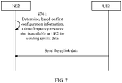
- FIG. 7 is a schematic flowchart of a second optional implementation of Embodiment 3 of the reference signal transmission method, said embodiment 3 not being according to the invention and being present for illustration purposes.
- this embodiment of the present invention further provides two optional implementations for ensuring UE uplink data transmission.
- an execution body of this embodiment of the present invention may further include user equipment UE.
- a cell serving second user equipment UE2 may belong to the NE2.
- the cell serving the UE2 may alternatively be a cell that belongs to the NE1 and that is adjacent to a cell of the NE2.
- steps of this implementation may include: S601: The UE2 determines, based on fourth configuration information, a time-frequency resource that is available for sending data.
- UpLink UpLink
- the UE2 may alternatively determine, based only on UE2-related first-RS configuration information instead of the entire first configuration information, a time-frequency resource that is available for receiving data.
- the fourth configuration information may be the same as the first configuration information, or may be a UE2-related time-frequency resource in the first configuration information.
- the UE2 may consider only a time-frequency resource that is used for the first RS and whose subcarrier or symbol is the same as that used by the UE2.
- a manner of obtaining the UE2-related first-RS configuration information by the UE2 is the same as the following manner of obtaining, by the UE2, the fourth configuration information that is the same as the first configuration information.
- a manner of obtaining the fourth configuration information by the UE2 may be similar to a manner of obtaining the first configuration information by the NE2.
- the UE2 may prestore the entire fourth configuration information, or may store a part of the first configuration information or not store the first configuration information.
- the NE2 After the NE2 obtains the first configuration information, for example, after the NE1 sends the second configuration information to the NE2, the NE2 sends first-RS configuration information required by the UE2 to the UE2.
- the method may further include: S610: The NE2 sends the fourth configuration information to the UE2.
- the fourth configuration information is used to indicate a time-frequency resource that is available to the UE2 for sending uplink data to the NE2, and the time-frequency resource that is available to the UE2 for sending the uplink data to the NE2 does not overlap with the time-frequency resource that is indicated by the first configuration information and that is used by the NE1 for sending the first RS.
- S610 is not a mandatory step.
- the NE2 may send the fourth configuration information by using physical layer signaling.
- the NE2 sends the fourth configuration information by using data control indication information DCI.
- the NE2 may send the fourth configuration information by using a radio resource control RRC message. If a subframe for the first RS may not be sent when the fourth configuration information is sent by using the RRC message, the UE may obtain a corresponding subframe from the RRC message, so as to reduce message sending overheads. Further, the NE2 may send the fourth configuration information by using higher layer signaling.
- the higher layer signaling may be, for example, a broadcast message or UE-specific information.
- the NE2 may send the fourth configuration information by using the broadcast message and/or the UE-specific information.
- the NE2 may send subframe information of the first RS and RE indication information of the first RS to the UE2 by using the broadcast message and the UE-specific information, respectively.
- the NE2 may send both subframe information of the first RS and RE indication information of the first RS to the UE2 by using the broadcast message.
- the NE2 may send both subframe information of the first RS and RE indication information of the first RS to the UE2 by using the UE-specific information.
- the NE2 may alternatively send the fourth configuration information to the UE2 by using a master information block MIB message or a system information block SIB message.
- the UE-specific information usually includes a specified UE identifier, that is, the UE-specific information is sent to some of UEs; a UE identifier is not limited in the broadcast message, that is, the broadcast message may be sent to all UEs in a cell.
- the fourth configuration information may include only a symbol at which the RE occupied by the first RS is located, so that the UE2 can determine the available time-frequency resource.
- the fourth configuration information includes the fourth RE indication information, and the RE that is occupied by the first RS and that is indicated by the fourth RE indication information overlaps with an RE of a physical uplink shared channel PUSCH of the UE2.
- the UE2 receives the fourth configuration information sent by the NE2, and the time-frequency resource that is determined by the UE2 and that is available for sending data is an RE that is in the PUSCH of the UE2 and that does not overlap with the RE occupied by the first RS.
- the UE2 may send data based on the time-frequency resource that is for sending uplink data and that is indicated by the NE2 during uplink data scheduling, and avoid using, for sending the uplink data, the time-frequency resource occupied by the first RS, so as to prevent the NE2 from incorrectly using, as the first RS for processing, the uplink data sent by the UE2 on the time-frequency resource occupied by the first RS.
- the UE when the NE1 sends the first RS to the NE2, the UE can still correctly receive downlink data.
- the method may include:
- the NE2 determines, based on the first configuration information, the time-frequency resource that is available to the UE2 for sending the uplink data.
- the UE2 may send the data based on the time-frequency resource that is for sending the uplink data and that is indicated by the NE2 during uplink data scheduling, so that the UE2 does not need to consider a collision, during uplink data sending, with the time-frequency resource occupied by the first RS.
- processing of the UE2 is exactly the same as that of existing UE.
- network device improvement can be supported without replacing the UE.
- the UE1 may alternatively perform the method performed by the UE2 shown in FIG. 6 and FIG. 7 .
- the UE2 may alternatively perform the method performed by the UE1 shown in FIG. 4 and FIG. 5 .
- this embodiment of the present invention further provides six optional implementations of the first configuration information.
- the NE1 may send the first RS by using a combination of one or more of the following optional implementations of the first configuration information.
- the CELL1 of the NE1 may include at least one antenna port
- the first RE indication information of the first configuration information may include: a pilot pattern corresponding to each antenna port of the NE1, where the pilot pattern is used to indicate an RE location for sending the first RS through each antenna port of the NE1.
- the RE location for sending the first RS through each antenna port may be corresponding to one pilot pattern, or the RE location for sending the first RS through each antenna port may constitute one pilot pattern.
- the CELL1 of the NE1 may include one or more antenna ports.
- the first RE indication information may be one pilot pattern or a plurality of pilot patterns, and each antenna port may be corresponding to one pilot pattern.
- Each pilot pattern may include at least one RE location.
- pilot patterns corresponding to more than one of the plurality of antenna ports may be the same.
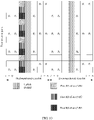
- FIG. 8 is a schematic diagram of a first optional implementation of the first RE indication information of the first configuration information.
- FIG. 9 is a schematic diagram of a second optional implementation of the first RE indication information of the first configuration information.
- FIG. 10 is a schematic diagram of a third optional implementation of the first RE indication information of the first configuration information.
- FIG. 11 is a schematic diagram of a fourth optional implementation of the first RE indication information of the first configuration information.
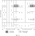
- FIG. 12 is a first-part schematic diagram of a fifth optional implementation of the first RE indication information of the first configuration information.
- FIG. 13 is a second-part schematic diagram of the fifth optional implementation of the first RE indication information of the first configuration information.
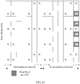
- FIG. 14 is a schematic diagram of a sixth optional implementation of the first RE indication information of the first configuration information.
- RE locations for sending the first RS through all the antenna ports may be a group of REs at a same symbol but on different subcarriers, as shown in FIG. 8 , or may be a group of REs located on a same subcarrier but at different symbols, as shown in FIG. 9 .
- R 0 , R 1 , R 2 , and R 3 are REs for a CRS.
- the NE1 may be an eNB1, and the NE2 may be an eNB2.
- An RE location for the first RS may avoid an RE location that collides with the CRS.
- the RE location for the first RS may also avoid an RE location that collides with an uplink DMRS and/or a downlink DMRS.
- the third RE indication information carried in the third configuration information notified by the NE1 to the UE1 may not explicitly indicate a specific RE location, but indicate only a carrier or symbol at which the first RS is located, so as to reduce message sending overheads.
- the fourth RE indication information carried in the fourth configuration information notified by the NE2 to the UE2 and the second RE indication information carried in the second configuration information notified by the NE1 to the NE2 may also indicate only the carrier or symbol at which the first RS is located, so as to reduce message sending overheads.
- the RE location for sending the first RS through each antenna port may be another predefined pilot pattern constituted by an RE location.
- the NE1 may have four antenna ports, where R 31 , R 32 , R 33 , and R 34 are first optional RE locations occupied by the first RS on the antenna ports, and R 35 , R 36 , R 37 , and R 38 may be second optional RE locations occupied by the first RS on the antenna ports.
- a pilot pattern corresponding to each antenna port may be one of a set of pilot patterns selectable for a channel state information-reference signal (Channel State Information Reference Signal, CSI-RS for short).
- CSI-RS Channel State Information Reference Signal
- a protocol provides a plurality of pilot patterns selectable for the CSI-RS, and any one of the pilot patterns may be selected for the first RS in this embodiment of the present invention.
- the second configuration information, the third configuration information, and the fourth configuration information may include only a type indication identifier of a pilot pattern for the CSI-RS, so that the RE location that is occupied by the first RS and that is indicated by the first RE indication information can be determined.
- the first RS is sent by using the pilot pattern for the CSI-RS, in an existing processing process of the UE, data is not received or sent by using a time-frequency resource occupied by the CSI-RS. Therefore, when any pilot pattern for the CSI-RS is used as the pilot pattern for the first RS, the UE can support network device improvement without changing the processing process.
- RE locations that are occupied by the first RS and that are corresponding to different antenna ports in a pilot pattern may be the same.
- the NE1 may send the first RS to the NE2 in a code division manner through the different antenna ports based on the RE locations that are for the first RS and that are indicated by the pilot pattern.
- the second configuration information, the third configuration information, and the fourth configuration information may indicate only a pilot pattern type.
- the pilot pattern type may be a quantity of antenna ports, and a network device or user equipment acting as a receiver may determine the first configuration information based on the pilot pattern type.
- the pilot pattern type refers to a parameter that is used to determine a pilot pattern and that is included in a type indication identifier of the pilot pattern.
- the first RS may be sent by using different pilot patterns through the antenna ports.
- type indication identifiers of the pilot patterns may be used to indicate, for different antenna port numbers, the pilot patterns used for sending the first RS.
- a type indication identifier of a pilot pattern includes a reference signal type, a quantity of antenna ports, an antenna port number, and a pilot pattern index.
- the pilot pattern index is used to indicate one of one or more pilot patterns.
- the reference signal type may include a cell-to-cell reference signal, a CSI-RS, a DMRS, an SRS, and the like.
- each of the CSI-RS, the DMRS, and the SRS may be corresponding to a selectable pilot pattern set, and each pilot pattern may be identified by using one or more of a quantity of antenna ports, an antenna port number, or a pilot pattern index.
- a type indication identifier of a pilot pattern may alternatively include no reference signal type, but include only one or more of a quantity of antenna ports, an antenna port number, or a pilot pattern index.
- the type indication identifier of the pilot pattern may include the quantity of antenna ports and the pilot pattern index, that is, the antenna port number is optional.
- the NE and the UE may determine the antenna port number based on the quantity of antenna ports, for example, select, based on a quantity of antenna ports and in a preset sequence, an antenna port number corresponding to the quantity of antenna ports from a set of antenna port numbers of selectable pilot patterns.
- antenna port numbers of pilot patterns selectable for sending a CSI-RS may be ⁇ 15, 16, 17, 18, 19, 20, 21, 22 ⁇ .
- a quantity of antenna ports used for sending the CSI-RS is 1, a corresponding antenna port number is 15.
- the type indication identifier of the pilot pattern may include only the quantity of antenna ports and the pilot pattern index.
- a pilot pattern index in an LTE protocol is used as an example. In the LTE protocol, 32 pilot patterns selectable for a CSI-RS are defined, and a pilot pattern index may range from 0 to 31. During specific implementation, a value may be different depending on a specific system. This is not limited herein.
- the type indication identifier of the pilot pattern may include the antenna port number.
- pilot patterns for sending a DMRS through antenna ports whose antenna port numbers are 7, 8, 11, and 13 are the same, and pilot patterns for sending the DMRS through antenna ports whose antenna port numbers are 9, 10, 12, and 14 are the same.
- the type indication identifier of the pilot pattern may include only the antenna port number.
- a value may be different depending on a specific system. This is not limited herein.
- the pilot pattern when the reference signal type is the SRS, the pilot pattern may be a pre-agreed pilot pattern, and the type indication identifier of the pilot pattern may indicate only the reference signal type.
- a specific pre-agreed pilot pattern may be a pilot pattern defined in an existing LTE protocol, or may be another pilot pattern. This is not limited herein.
- subframe information in first configuration information of first RSs sent to a same network device may be the same, and RE locations in the first configuration information of the first RSs sent to the same network device may be the same or may be different. If the RE locations are the same, a same RE may be multiplexed for all the first RSs in an OCC code division manner.
- the NE1 may be an eNB1, and the NE2 may be an eNB2, optionally.
- Cells of the eNB1, the eNB2, and an eNB3 each have four antenna ports.
- a pilot pattern corresponding to each antenna port may be shown in FIG. 12 and FIG. 13 .
- R 31 , R 32 , R 33 , and R 34 are first optional RE locations occupied by the first RS on the antenna ports
- R 35 , R 36 , R 37 , and R 38 may be second optional RE locations occupied by the first RS on the antenna ports.
- R 31 , R 32 , R 33 , and R 34 may be RE locations for sending the first RS through four antenna ports of the eNB1, and R 35 , R 36 , R 37 , and R 38 may be RE locations for sending the first RS through four antenna ports of the eNB2.
- OCC code division may be used for R 31 and R 32 of the eNB1
- OCC code division may be used for R 33 and R 34
- OCC code division may be used for R 35 and R 36 of the eNB2
- OCC code division may be used for R 37 and R 38 .
- R 31 , R 32 , R 35 , and R 36 may be RE locations for sending the first RS through four antenna ports of the eNB1, and R 33 , R 34 , R 37 , and R 38 are RE locations for sending the first RS through four antenna ports of the eNB2.
- R 31 and R 32 may be RE locations for sending the first RS through four antenna ports of the eNB1
- R 33 and R 34 may be RE locations for sending the first RS through four antenna ports of the eNB2
- R 35 and R 36 may be RE locations for sending the first RS through four antenna ports of the eNB3
- R 37 and R 38 may be RE locations for sending the first RS through four antenna ports of the eNB4.
- a subframe for the first RS in the first configuration information may be a dedicated subframe.
- a general subframe usually may be used for sending control information such as a PDCCH, data information such as a PDSCH, a reference signal such as a CRS, and other information.
- the dedicated subframe defined in this embodiment of the present invention is used for sending the first RS, or the first RS and control information. In other words, data information such as a PDSCH is not sent in the dedicated subframe.
- an MBSFN subframe configuration manner may be used as a configuration manner of the subframe for the first RS.
- An MBSFN subframe configuration result may be specifically: One or more of 10 subframes are an MBSFN subframe.
- the subframe for the first RS in the first configuration information may be a subframe for sending a PDCCH or a CRS.
- Data included in the subframe may have the following cases. In a first case, only the first RS is included, and no PDCCH, CRS, PMCH, or other information is included. In a second case, the first RS and PDCCH information are included, or the first RS and CRS information are included, or the first RS, PDCCH information, and CRS information are included.
- the PDCCH information in the subframe determined by the subframe information of the first RS may be located at the first to the fourth symbols. Using such a sending manner does not affect a PDCCH information capacity and can reduce impact on normal interaction information of UE.
- the subframe information of the first RS in the first configuration information may be one of a set of subframe information selectable for a demodulation reference signal (Demodulation Reference Signal, DMRS), and one of a set of symbol locations selectable for the DMRS may be selected as the first RE indication information in the first configuration information.
- DMRS Demodulation Reference Signal
- the first configuration information may include at least one of pilot pattern indication information and DMRS antenna port number indication information.
- the subframe information of the first RS in the first configuration information may be one of a set of subframe information selectable for a sounding reference signal SRS, and one of a set of symbol locations selectable for the SRS may be selected as the first RE indication information in the first configuration information.
- SRS sounding reference signal
- subframe information selectable for the SRS may also be used for sending the first RS in this embodiment of the present invention, and the subframe for the first RS may also include a subframe period and a subframe offset.
- the subframe information and symbol locations selectable for the SRS are used for sending, so that when notifying the UE1, the NE1 may use a process of notifying UE of an SRS by a base station in the current protocol, with no need to use a newly defined message; the UE can also follow a manner of avoiding receiving and sending data in a subframe and an RE that are used for an SRS in the current protocol, to avoid receiving and sending data in the subframe and RE that are used for the first RS.
- a subframe that the NE2 instructs the user equipment served by the NE2 to use for sending an SRS may be used as the subframe for the first RS.
- An RE that the NE2 instructs the user equipment served by the NE2 to use for sending the SRS may be used as the first RE indication information.
- the NE1 may send the first RS by using the subframe and the RE that are used, by the user equipment served by the NE2, for sending the SRS.
- the subframe and the RE that are used by the NE1 for sending the first RS to the NE2 do not occupy a time-frequency resource the same as that used, by the user equipment served by the NE2, for sending a PUSCH.
- the NE1 may pre-obtain the subframe and the RE that are used, by the user equipment served by the NE2, for sending the SRS, so as to determine a selectable subframe and selectable first RE indication information of the first RS in the first configuration information.
- the NE1 may not explicitly indicate that the subframe is the subframe for sending the SRS, but merely send, in an SRS sending manner, the first RS in a subframe and an RE that are selectable for the SRS.
- included data on an RE at a symbol corresponding to the subframe determined by the subframe information of the first RS may have several cases. In a first case, only the first RS is included; in other words, information other than the first RS is excluded. In a second case, both SRS information and the first RS are included.
- the first RS and the SRS information may be located on different subcarriers.
- the first RS can also be sent by making full use of an idle RE resource in a subframe for sending the SRS, thereby reducing a waste of uplink resources of UE.
- the RE that is occupied by the first RS and that is indicated by the first RE indication information may alternatively be located at the last one or more symbols, for example, one, two, or three symbols, of the subframe determined by the subframe information of the first RS.
- the UE sends the SRS at the last symbol in a comb-teeth-shaped manner. Therefore, the first RS may be sent by using a blank area. Therefore, even if the first RS is being sent, SRS and uplink data sending of the UE is not affected, and only an SRS capacity is reduced.
- subcarriers occupied by the first RS may be alternate subcarriers.
- Such a sending manner has relatively small impact on uplink data of the UE. For example, if the UE sends the first RS at an interval of one subcarrier, six subcarriers are wasted for one RB; if the UE sends the first RS at an interval of two subcarriers, four subcarriers are wasted for one RB; and so on.
- the network devices are TDD-mode base stations and have a same working frequency, for example, the NE1 is the eNB1, the NE2 is the eNB2, and working frequencies of the NE1 and the NE2 are both f1, the NE1 sends the first RS by using an antenna of the CELL1, a timeslot in which the NE1 sends the first RS needs to be configured as a downlink timeslot, the NE2 receives the first RS by using an antenna of the CELL2, and a timeslot in which the NE2 receives the first RS needs to be configured as an uplink timeslot.
- FIG. 15 is a schematic diagram of a scenario of an optional implementation of the first configuration information.
- the first configuration information may include a scrambling code.
- the scrambling code is used by the NE1 to scramble the first RS for sending.
- the scrambling code can be further used as an identifier of the first RS.
- one network device when one network device receives reference signals that are sent by a plurality of network devices and that are provided in this embodiment of the present invention, that is, a plurality of NEls send first RSs to one NE2, and each NE1 may use a device identifier of the NE1 as a scrambling code, the NE2 may distinguish, based on scrambling codes, between first RSs from different network devices, and may directly discard a reference signal that is scrambled by using a non-expected scrambling code.
- the scrambling code may alternatively be a cell identity.
- the NE2 may further distinguish between first RSs sent through antenna ports of different cells of the NE1s.
- the first configuration information may further include a period.
- the NE1 periodically sends the first RS to the NE2.
- the NE1 further receives, based on fifth configuration information, a second RS sent by the NE2.
- the fifth configuration information includes a time-frequency resource used by the NE2 for sending the second RS
- this embodiment of the present invention further provides an optional implementation of an reference information transmission method.
- the implementation provided in this embodiment of the present invention further includes: sending, by the NE1, the first RS to the NE2 by using the subframe information of the first RS, and sending, by the NE2, the second RS to the NE1 by using subframe information of the second RS.
- the first configuration information includes the subframe information of the first RS
- the fifth configuration information includes the subframe information of the second RS.
- the NE1 sends the first RS in a downlink timeslot of the subframe indicated by the subframe information of the first RS, and the NE2 sends the second RS in an uplink timeslot of the subframe indicated by the subframe information of the second RS.
- An intersection set of the subframe information of the first RS and the subframe information of the second RS is nonempty.
- a front section and a rear section of the subframe determined by the subframe information of the first RS respectively include an uplink timeslot and a downlink timeslot, or a front section and a rear section of the subframe determined by the subframe information of the first RS respectively include a downlink timeslot and an uplink timeslot.
- the NE1 and the NE2 may belong to a same cell coordination set, the NE1 may periodically send the first RS to the NE2, and the NE2 may periodically send the second RS to the NE1.
- a reverse operation is performed.
- the cell whose cell ID is identified as the even number is in a sending state, and the NE to which the cell in the sending state belongs sends the first RS; the cell whose cell ID is identified as the odd number is in a receiving state, and the NE to which the cell in the receiving state belongs receives the first RS.
- the network device to which the cell whose cell ID is the odd number belongs and the network device to which the cell whose cell ID is the even number belongs may use RS sending manners of the NE1 and the NE2, respectively.
- another distinguishing manner may be used to distinguish between cells or NEs in a sending state and a receiving state.
- T may be a period for sending the first RS
- the first configuration information may include the subframe information of the first RS
- the fifth configuration information may include the subframe information of the second RS
- the subframe information of the first RS includes a subframe period and a subframe offset of the first RS
- the subframe information of the second RS includes a subframe period and a subframe offset of the second RS
- the subframe period of the first RS is the same as the subframe period of the second RS
- an interval between the subframe offset of the first RS and the subframe offset of the second RS is one period.
- the base stations may send the RSs in one downlink timeslot.
- the timeslot is an uplink timeslot, and the base stations in the second cell coordination set simultaneously receive the RSs.
- sending may be performed in a reverse direction.
- FIG. 16 is a schematic diagram of a scenario of another optional implementation of the first configuration information. It should be noted that a period for the NE1 may be different from a period for the NE2.
- the network device may send the first RS in a time division multiplexing manner, a frequency division multiplexing manner, a code division multiplexing manner, or another time-frequency resource multiplexing manner, to reduce a waste of uplink resources or downlink resources of UE.
- the network device may use a time division multiplexing manner, a frequency division multiplexing manner, a code division multiplexing manner, or another time-frequency resource multiplexing manner, to reduce a waste of uplink resources or downlink resources of UE.
- the following describes a relationship between the second configuration information, the third configuration information, and the fourth configuration information.
- Content of the second configuration information, the third configuration information, and the fourth configuration information each may be a subset of the first configuration information, and may include different content, provided that the following is ensured:
- the time-frequency resource for sending the first RS can be determined based on the second configuration information, to ensure that the NE2 can receive the first RS;
- a time-frequency resource that may collide with UE receiving the third configuration information can be determined based on the third configuration information, to ensure that the UE receiving the third configuration information does not receive data incorrectly;
- a time-frequency resource that may collide with UE receiving the fourth configuration information can be determined based on the fourth configuration information, to ensure that the UE receiving the fourth configuration information does not send data incorrectly, so that receiving the first RS by the NE2 is not affected.
- this embodiment of the present invention provides several optional implementations of the second configuration information, the third configuration information, and the fourth configuration information.
- the NE1 Before the NE1 sends the first RS to the NE2 based on the first configuration information in S101, the NE1 sends the second configuration information to the NE2, where the second configuration information includes the subframe information of the first RS in the first configuration information, and the second RE indication information.
- the second RE indication information may include the first RE indication information in the first configuration information, the symbol at which the RE that is occupied by the first RS and that is indicated by the first RE indication information is located, the subcarrier on which the RE that is occupied by the first RS and that is indicated by the first RE indication information is located, or a type indication identifier of a pilot pattern corresponding to each antenna port used by the NE1 to send the first RS.
- the NE1 may send the third configuration information to the UE1 before the NE1 sends downlink data to the UE1.
- the third configuration information may include the subframe information of the first RS in the first configuration information, and/or the third RE indication information.
- the third RE indication information includes the first RE indication information, the symbol at which the RE that is occupied by the first RS and that is indicated by the first RE indication information is located, the subcarrier on which the RE that is occupied by the first RS and that is indicated by the first RE indication information is located, or the type indication identifier of the pilot pattern corresponding to each antenna port of the NE1.
- the fourth configuration information may include the subframe information of the first RS in the first configuration information, and/or the fourth RE indication information.
- the fourth RE indication information includes the RE that is occupied by the first RS and that is indicated by the first RE indication information, the symbol at which the RE that is occupied by the first RS and that is indicated by the first RE indication information is located, the subcarrier on which the RE that is occupied by the first RS and that is indicated by the first RE indication information is located, or the type indication identifier of the pilot pattern corresponding to each antenna port of the CELL1.
- the NE2 may send the fourth configuration information to the UE2 by using a resource block assignment Resource Block Assignment message.
- this embodiment of the present invention further provides four types of new message formats for sending, by the network device, the third configuration information and the fourth configuration information.
- the third configuration information and the fourth configuration information in this embodiment of the present invention may be sent by using at least one message in the following message formats.
- the first RS may be referred to as a cell-to-cell (cell to cell, C2C for short) reference signal.
- Configurations and newly-added information element formats of the cell-to-cell reference signal are as follows:
- a first type of newly-added message format is a newly-added information element in RRC signaling.
- Newly-added configuration information of the cell-to-cell reference signal may include a period for the first RS, a time-frequency resource for the first RS, a quantity of antenna ports for the first RS, and the like.
- the IE C2C-RS-Config is used to specify the C2C (cell to cell) reference signal configuration.
- a second type of newly-added message format is a newly-added information element in a broadcast message.
- a new message format of a broadcast message may include a period for the first RS, a time-frequency resource for the first RS, a quantity of antenna ports for the first RS, and the like.
- the broadcast message may be sent by using a PBCH.
- newly-added information elements in a MIB message are as follows:
- a third type of newly-added message format is a newly-added information element in physical layer signaling.
- a new message format of physical layer signaling includes two types.
- a first type of physical layer signaling is used to indicate a time-frequency resource that is available for downlink data.
- a C2C RS configuration indication may be added to DCI, and a flag bit C2C RS indicator is used to indicate the RE location occupied by the first RS.
- An enumerated value of the flag bit may be corresponding to one or more pilot patterns.
- the flag bit may carry a type indication identifier of the pilot pattern, for example, may be a combination of one or more of a reference signal type, a quantity of antenna ports, an antenna port number, or a pilot pattern index. Specifically, the following information is added to the DCI.
- a second type of physical layer signaling is used to indicate a time-frequency resource that is available for uplink data.
- a C2C RS configuration indication may be added to DCI, and a flag bit C2C RS symbol indicator may indicate only a symbol occupied by the first RS. Specifically, the following information is added to the DCI.
- bit rate Available REs * Modulation scheme ⁇ CRC verification code / tbsize
- a transmission bit rate of a network device can be improved when the various implementations of the first configuration information that are provided in this embodiment of the present invention and that reduce a quantity of occupied REs are used.
- this embodiment of the present invention further provides four optional implementations of sending, by the NE1, the first RS to the NE2.
- the NE1 may send the first RS to the NE2 by using digital beamforming and analog beamforming.
- the sending, by the NE1, the first RS to the NE2 may specifically include: sending, by the NE1, the first RS to the NE2 in a non-beamforming form.
- the sending, by the NE1, the first downlink data and the scheduling result of the first downlink data to the NE2 may specifically include: sending, by the NE1, a precoding matrix of the first downlink data to the NE2, so that the NE2 obtains the un-precoded first channel based on the first RS that is sent in the non-beamforming form, and restores the first interference signal based on the un-precoded first channel, the precoding matrix of the first downlink data, and the scheduling result of the first downlink data.
- the first downlink data may be un-coded or may be coded. If the first downlink data is un-coded, the precoding matrix also needs to be sent to the NE2.
- the sending, by the NE1, the first RS to the NE2 may specifically include: sending, by the NE1, the first RS to the NE2 in the analog beamforming form.
- the sending, by the NE1, the first RS to the NE2 may specifically include: sending, by the NE1, the first RS to the NE2 in the digital beamforming form.
- a fourth optional sending manner of the first RS if the NE1 sends the first downlink data to the UE2 in a digital beamforming form,
- FIG. 17 is a schematic structural diagram of a network device according to an embodiment of the present invention.
- the network device provided in this embodiment of the present invention may be used as a first network device NE1, and the NE1 may include: a first transceiver module 11, configured to send, for the NE1 to which a first cell CELL1 belongs, a first reference signal RS based on first configuration information to a second network device NE2 to which a second cell CELL2 belongs, where the first configuration information includes information used to indicate a time-frequency resource used by the NE1 for sending the first RS.
- a first transceiver module 11 configured to send, for the NE1 to which a first cell CELL1 belongs, a first reference signal RS based on first configuration information to a second network device NE2 to which a second cell CELL2 belongs, where the first configuration information includes information used to indicate a time-frequency resource used by the NE1 for sending the first RS.
- the first RS is used by the NE2 to cancel, based on the first RS, interference from the NE1 to first uplink data.
- the first uplink data is from user equipment served by the NE2.
- the NE1 further includes: a processing module 12, configured to detect that uplink-downlink subframe configurations of the CELL1 and the CELL2 are inconsistent.
- a processing module 12 configured to detect that uplink-downlink subframe configurations of the CELL1 and the CELL2 are inconsistent.
- the NE1 may further include: a second transceiver module 13, configured to send first downlink data and/or a scheduling result of first downlink data to the NE2, where the first downlink data is sent by the NE1 to user equipment served by the first cell CELL1 of the NE1.
- a second transceiver module 13 configured to send first downlink data and/or a scheduling result of first downlink data to the NE2, where the first downlink data is sent by the NE1 to user equipment served by the first cell CELL1 of the NE1.
- the second transceiver module 13 may be configured to send the first downlink data and/or the scheduling result of the first downlink data to the NE2 by using an X2 interface between the NE1 and the NE2.
- the first configuration information includes:
- the first cell of the NE1 includes at least one antenna port
- the first RE indication information includes: a pilot pattern corresponding to each antenna port of the CELL1, where the pilot pattern is used to indicate an RE for sending the first RS through each antenna port of the first cell.
- At least one of pilot patterns corresponding to all antenna ports of the NE1 belongs to a set of pilot patterns selectable for a channel state information-reference signal CSI-RS.
- a subframe determined by the subframe information of the first RS belongs to a set of subframes selectable for a sounding reference signal SRS of the NE2.
- the RE that is occupied by the first RS and that is indicated by the first RE indication information is different from an RE used for the SRS of the NE2; and/or the RE that is occupied by the first RS and that is indicated by the first RE indication information is different from a subcarrier on which an RE used for the SRS of the NE2 is located; and/or the RE that is occupied by the first RS and that is indicated by the first RE indication information is different from a symbol at which an RE used for the SRS of the NE2 is located.
- a symbol at which the RE that is occupied by the first RS and that is indicated by the first RE indication information is located is the last symbol of the subframe determined by the subframe information of the first RS.
- the subframe information of the first RS indicates a dedicated subframe
- the dedicated subframe carries the first RS
- the subframe determined by the subframe information of the first RS may include only the first RS.
- the subframe determined by the subframe information of the first RS may include the first RS and physical downlink control channel PDCCH information, or include the first RS and CRS information, or include the first RS, PDCCH information, and CRS information.
- the subframe determined by the subframe information of the first RS includes both the first RS and the PDCCH information, where the PDCCH information is located at the first to the fourth symbols.
- the first configuration information further includes a scrambling code.
- the scrambling code is used by the NE1 to scramble the first RS.
- the second transceiver module 13 is further configured to send second configuration information to the NE2, where the second configuration information includes the subframe information of the first RS in the first configuration information, and/or second RE indication information.
- the second RE indication information includes the first RE indication information in the first configuration information; or at least one of the symbol at which the RE that is occupied by the first RS and that is indicated by the first RE indication information is located, a subcarrier on which the RE that is occupied by the first RS and that is indicated by the first RE indication information is located, and a type indication identifier of the pilot pattern corresponding to each antenna port used by the NE1 to send the first RS.
- the processing module 14 is further configured to send, based on the first configuration information, a time-frequency resource that is available for sending downlink data to first user equipment UE1 served by the first cell.
- the first transceiver module 11 is further configured to send third configuration information to the UE1.
- the third configuration information includes the subframe information of the first RS in the first configuration information, and/or third RE indication information.
- the third RE indication information includes the first RE indication information; or at least one of the symbol at which the RE that is occupied by the first RS and that is indicated by the first RE indication information is located, the subcarrier on which the RE that is occupied by the first RS and that is indicated by the first RE indication information is located, and the type indication identifier of the pilot pattern corresponding to each antenna port of the NE1.
- the first transceiver module 11 is specifically configured to send the third configuration information by using a broadcast message and/or UE-specific information.
- the first transceiver module 11 is specifically configured to send the third configuration information by using higher layer signaling and/or physical layer signaling.
- the higher layer signaling includes a radio resource control RRC message.
- the RRC message includes a master information block MIB message or a system information block SIB message.
- the physical layer signaling includes data control indication information DCI.
- the third configuration information includes the third RE indication information, and the RE that is occupied by the first RS and that is indicated by the third RE indication information overlaps with an RE of a physical downlink shared channel PDSCH of the UE1.
- the first transceiver module 11 is specifically configured to send the third configuration information to the UE1 by using the UE-specific information, where the third configuration information includes the third RE indication information.
- An RE that is indicated by the third RE indication information and on which the first RS collides with the PDSCH of the UE1 is an intersection set of the RE that is occupied by the first RS and that is indicated by the first RE indication information and the PDSCH of the UE1.
- the third configuration information includes the subframe information of the first RS and the third RE indication information.
- the first transceiver module 11 is specifically configured to send the subframe information of the first RS in the third configuration information to the UE1 by using the broadcast message; and the first transceiver module 11 is further specifically configured to send the third RE indication information in the third configuration information to the UE1 by using the UE-specific information.
- the first transceiver module 11 is further configured to receive, based on fifth configuration information, a second RS sent by the NE2, where the fifth configuration information includes a time-frequency resource used by the NE2 for sending the second RS.
- the first configuration information includes the subframe information of the first RS
- the fifth configuration information includes subframe information of the second RS.
- the first transceiver module 11 is further configured to send the first RS in the subframe determined by the subframe information of the first RS.
- the first transceiver module 11 is further configured to receive the second RS in a subframe determined by the subframe information of the second RS.
- an intersection set of the subframe determined by the subframe information of the first RS and the subframe determined by the subframe information of the second RS is nonempty, and a front section and a rear section of the subframe determined by the subframe information of the first RS respectively include an uplink timeslot and a downlink timeslot, or a front section and a rear section of the subframe determined by the subframe information of the first RS respectively include a downlink timeslot and an uplink timeslot.
- the first transceiver module 11 is further configured to send the first RS in the downlink timeslot of the subframe indicated by the subframe information of the first RS, and receive the second RS in the uplink timeslot of the subframe indicated by the subframe information of the first RS.
- the first configuration information includes the subframe information of the first RS
- the fifth configuration information includes the subframe information of the second RS
- the subframe information of the first RS includes a subframe period and a subframe offset of the first RS
- the subframe information of the second RS includes a subframe period and a subframe offset of the second RS
- the subframe period of the first RS is the same as the subframe period of the second RS
- an interval between the subframe offset of the first RS and the subframe offset of the second RS is one period.
- the first transceiver module is further configured to periodically send the first RS to the NE2, and periodically receive the second RS sent by the NE2.
- the first transceiver module 11 receives, through each antenna port of the CELL1, the second RS that is sent through each antenna port of the CELL2 of the NE2.
- the subframe information of the second RS is determined by the NE2 based on a cell identity of the CELL2.
- the cell identity of the CELL2 is an even number
- a cell identity of the CELL1 is an odd number
- the subframe determined by the subframe information of the first RS is a first subframe
- the subframe determined by the subframe information of the second RS is a second subframe
- the second subframe is a subframe after the first subframe
- the cell identity of the CELL2 is an odd number
- a cell identity of the CELL1 is an even number
- the subframe determined by the subframe information of the first RS is a first subframe
- the subframe determined by the subframe information of the second RS is a second subframe
- the second subframe is a subframe after the first subframe
- the first transceiver module 11 is configured to send the first RS to each antenna port of the CELL2 of the NE2 through each antenna port of the CELL1.
- the subframe information of the first RS is determined by the NE1 based on the cell identity of the CELL1.
- the CELL1 and the CELL2 belong to one cell coordination set.
- the network device in this embodiment may be configured to implement the technical solutions in the method embodiment shown in FIG. 1 to FIG. 16 , and implementation principles and technical effects thereof are similar. Details are not described herein again.
- FIG. 18 is a schematic structural diagram of another network device according to an embodiment of the present invention.
- the network device provided in this embodiment of the present invention may be used as a second network device NE2, and the NE2 may include: a first transceiver module 21, configured to receive, for the NE2 to which a second cell CELL2 belongs, based on first configuration information, a first reference signal RS sent by a first network device NE1 to which a first cell CELL1 belongs, where the first configuration information includes information used to indicate a time-frequency resource used by the NE1 for sending the first RS.
- a first transceiver module 21 configured to receive, for the NE2 to which a second cell CELL2 belongs, based on first configuration information, a first reference signal RS sent by a first network device NE1 to which a first cell CELL1 belongs, where the first configuration information includes information used to indicate a time-frequency resource used by the NE1 for sending the first RS.
- the NE2 may further include a processing module 22, configured to cancel, based on the first RS, interference from the NE1 to first uplink data, where the first uplink data is from user equipment served by the NE2.
- a processing module 22 configured to cancel, based on the first RS, interference from the NE1 to first uplink data, where the first uplink data is from user equipment served by the NE2.
- the processing module 22 may be configured to: obtain a first channel between the NE1 and the NE2 based on the first RS;
- the NE2 may include a second transceiver module 13, configured to receive first downlink data and/or a scheduling result of first downlink data sent by the NE1, where the first downlink data is sent by the NE1 to user equipment served by the NE1.
- a second transceiver module 13 configured to receive first downlink data and/or a scheduling result of first downlink data sent by the NE1, where the first downlink data is sent by the NE1 to user equipment served by the NE1.
- the processing module is specifically configured to restore the first interference signal based on the first channel and at least one of the first downlink data and the scheduling result of the first downlink data.
- the second transceiver module 23 is specifically configured to receive the first downlink data and the scheduling result of the first downlink data by using an X2 interface between the NE2 and the NE1.
- the first indication information includes:
- the second transceiver module 23 is further configured to receive second configuration information sent by the NE1, where the second configuration information includes the subframe information of the first RS, and/or second RE indication information.
- the second RE indication information includes an RE location for the first RS, or at least one of a symbol at which the RE occupied by the first RS is located, a subcarrier on which the RE occupied by the first RS is located, and a type indication identifier of a pilot pattern corresponding to each antenna port used in the CELL1 to send the first RS.
- the processing module 22 is further configured to determine the first configuration information based on the second configuration information.
- the processing module 22 is further configured to determine, based on the first configuration information, an available time-frequency resource to be allocated to second user equipment UE2 for sending uplink data, where the UE2 is served by the CELL2.
- the first transceiver module 21 is further configured to send fourth configuration information to the UE2.
- the fourth configuration information includes the subframe information of the first RS in the first configuration information, and/or fourth RE indication information.
- the fourth RE indication information includes at least one of the RE that is occupied by the first RS and that is indicated by the first RE indication information, the symbol at which the RE that is occupied by the first RS and that is indicated by the first RE indication information is located, the subcarrier on which the RE that is occupied by the first RS and that is indicated by the first RE indication information is located, or the type indication identifier of the pilot pattern corresponding to each antenna port of the CELL1.
- the first transceiver module 21 is specifically configured to send the third configuration information by using a broadcast message and/or UE-specific information.
- the first transceiver module 21 is specifically configured to send the third configuration information by using higher layer signaling and/or physical layer signaling.
- the higher layer signaling includes a radio resource control RRC message.
- the RRC message includes a master information block MIB message or a system information block SIB message.
- the physical layer signaling includes data control indication information DCI.
- the first configuration information includes the first RE indication information, and the RE that is occupied by the first RS and that is indicated by the first RE indication information overlaps with an RE of a physical uplink shared channel PUSCH of the UE2.
- the first transceiver module 21 is further configured to send the fourth configuration information to the UE2 by using the UE-specific information, where the fourth configuration information includes the fourth RE indication information.
- An RE location that is indicated by the fourth RE indication information and at which the PUSCH collides with the RE occupied by the first RS is an intersection set of an RE location indicated by the first RE indication information and the PUSCH of the UE2.
- the fourth configuration information includes a subframe for the first RS and the fourth RE indication information.
- the first transceiver module 21 is specifically configured to send the subframe information of the first RS in the fourth configuration information to the UE2 by using the broadcast message.
- the first transceiver module 21 is specifically configured to send the fourth RE indication information in the fourth configuration information to the UE2 by using the UE-specific information.
- the network device in this embodiment may be configured to implement the technical solutions in the method embodiment shown in FIG. 1 to FIG. 16 , and implementation principles and technical effects thereof are similar. Details are not described herein again.
- FIG. 19 is a schematic structural diagram of user equipment according to an embodiment of the present invention.
- the user equipment provided in this embodiment of the present invention may include: a processing module 32, configured to determine, based on third configuration information, a time-frequency resource that is available for receiving data or sending data.
- the third configuration information is used to indicate all or some of time-frequency resources occupied by a first reference signal RS.
- the first RS is sent by a first network device NE1 to which a first cell CELL1 belongs, to a second network device NE2 to which a second cell CELL2 belongs.
- the user equipment may further include: a transceiver module 31, configured to receive the third configuration information.
- the transceiver module 31 is configured to receive a broadcast message and/or UE-specific information, where the broadcast message and/or the UE-specific information include/includes the third configuration information.
- the transceiver module 31 is configured to receive higher layer signaling and/or physical layer signaling, where the higher layer signaling and/or the physical layer signaling include/includes the third configuration information.
- the higher layer signaling includes a radio resource control RRC message.
- the RRC message includes a master information block MIB message or a system information block SIB message.
- the physical layer signaling includes data control indication information DCI.
- the third configuration information includes subframe information of the first RS, and/or third RE indication information.
- the third RE indication information includes an RE location occupied by the first RS; or at least one of a symbol at which an RE occupied by the first RS is located, a subcarrier on which an RE occupied by the first RS is located, and a type indication identifier of a pilot pattern corresponding to an RE occupied by the first RS.
- a cell serving the user equipment is the CELL1
- the third configuration information is sent by the NE1
- the processing module 32 may be specifically configured to determine, based on the third configuration information, a time-frequency resource that is available for receiving data.
- the third configuration information includes the third RE indication information, and the RE that is occupied by the first RS and that is indicated by the third RE indication information overlaps with an RE of a physical downlink shared channel PDSCH of the user equipment.
- the transceiver module 31 is specifically configured to receive the third configuration information by using UE-specific information sent by the NE1, and the time-frequency resource that is determined by the processing module 32 and that is available for receiving data is an RE that is in the PDSCH of the user equipment and that does not overlap with the RE occupied by the first RS.
- a cell serving the user equipment is the CELL2
- the third configuration information is sent by the NE2
- the processing module 32 may be specifically configured to determine, based on the third configuration information, a time-frequency resource that is available for sending data.
- the third configuration information includes the third RE indication information, and the RE that is occupied by the first RS and that is indicated by the third RE indication information overlaps with an RE of a physical uplink shared channel PUSCH of the user equipment.
- the transceiver module 31 is specifically configured to receive the third configuration information by using UE-specific information sent by the NE2, and the time-frequency resource that is determined by the processing module 32 and that is available for sending data is an RE that is in the PUSCH of the user equipment and that does not overlap with the RE occupied by the first RS.
- FIG. 20 is an optional schematic structural diagram of a network device according to an embodiment of the present invention.
- this embodiment of the present invention provides a network device, where the network device has a function of implementing behaviors of the first network device in the foregoing method in actuality.
- a structure of the network device includes a wireless communications interface 111, for example, a transmitter and a receiver, and a network communications interface 113.
- the wireless communications interface is configured to support communication between the network device and a network device and user equipment.
- the transmitter is configured to send the information or data in the foregoing method to the network device and the user equipment.
- the receiver is configured to support the network device in receiving the information or data sent by the network device and the user equipment in the foregoing method.
- the network communications interface is configured to support communication between the network devices.
- the structure of the network device may further include a demodulator and/or a decoder.
- the demodulator is configured to demodulate or despread and demodulate the information or data in the foregoing method.
- the decoder is configured to decode or descramble and decode the information or data in the foregoing method.
- the structure of the network device may further include a processor 112.
- the processor is configured as supporting the network device in performing a corresponding function in the foregoing method. It can be understood that, when the structure of the network device does not include the demodulator and/or the decoder, functions/a function of the demodulator and/or the decoder may also be implemented in the receiver or the processor.
- the network device may further include a memory 114, and the memory is configured to couple to the processor, and store a program instruction and data that are necessary for the network device.
- the network device may further include an interface unit, configured to support communication with another network device, for example, communication with a core network node.
- the wireless communications interface may be configured to send a first reference signal to a network device or receive a first reference signal sent by another network device, and may also be configured to send third configuration information or fourth configuration information to user equipment.
- FIG. 20 shows only a simplified design of the network device.
- the network device may include any quantities of transmitters, receivers, processors, memories, and the like. All network devices that can implement the embodiments of the present invention fall within the protection scope of the embodiments of the present invention.
- FIG. 21 is an optional schematic structural diagram of another network device according to an embodiment of the present invention.
- this embodiment of the present invention provides a network device, where the network device has a function of implementing behaviors of the second network device in the foregoing method in actuality.
- a structure of the network device includes a wireless communications interface 121, for example, a transmitter and a receiver, and a network communications interface 123.
- the wireless communications interface is configured to support communication between the network device and a network device and user equipment.
- the transmitter is configured to send the information or data in the foregoing method to the network device and the user equipment.
- the receiver is configured to support the network device in receiving the information or data sent by the network device and the user equipment in the foregoing method.
- the network communications interface is configured to support communication between the network devices.
- the structure of the network device may further include a demodulator and/or a decoder.
- the demodulator is configured to demodulate or despread and demodulate the information or data in the foregoing method.
- the decoder is configured to decode or descramble and decode the information or data in the foregoing method.
- the structure of the network device may further include a processor 122.
- the processor is configured as supporting the network device in performing a corresponding function in the foregoing method. It can be understood that, when the structure of the network device does not include the demodulator and/or the decoder, functions/a function of the demodulator and/or the decoder may also be implemented in the receiver or the processor.
- the network device may further include a memory 124, and the memory is configured to couple to the processor, and store a program instruction and data that are necessary for the network device.
- the network device may further include an interface unit, configured to support communication with another network device, for example, communication with a core network node.
- the wireless communications interface may be configured to send a first reference signal to a network device or receive a first reference signal sent by another network device, and may also be configured to send third configuration information or fourth configuration information to user equipment.
- FIG. 21 shows only a simplified design of the network device.
- the network device may include any quantities of transmitters, receivers, processors, memories, and the like. All network devices that can implement the embodiments of the present invention fall within the protection scope of the embodiments of the present invention.
- FIG. 22 is an optional schematic structural diagram of user equipment according to an embodiment of the present invention.
- a structure of the user equipment includes a transceiver 131, for example, a receiver and a transmitter.
- the transmitter is configured to support the user equipment in sending the information or data in the foregoing method to a network device.
- the receiver is configured to support the user equipment in receiving the information or data sent by the network device in the foregoing method.
- the structure of the user equipment may further include an encoder and/or a modulator.
- the encoder is configured to encode or encode and scramble the information or data in the foregoing method.
- the modulator is configured to modulate or modulate and spread the information or data in the foregoing method.
- the structure of the user equipment may further include a processor 132.
- the processor is configured as supporting the user equipment in performing a corresponding function in the foregoing method. It can be understood that, when the structure of the user equipment does not include the modulator and/or the encoder, functions/a function of the modulator and/or the encoder may also be implemented in the transmitter or the processor.
- the user equipment may further include a memory 134, and the memory is configured to couple to the processor, and store a program instruction and data that are necessary for the user equipment.
- a wireless communications interface may be configured to receive third configuration information or fourth configuration information sent by the network device.
- FIG. 22 shows only a simplified design of the user equipment.
- the user equipment may include any quantities of transmitters, receivers, processors, memories, and the like. All user equipment that can implement the embodiments of the present invention fall within the protection scope of the embodiments of the present invention.
- An embodiment of the present invention provides a communications system.
- the system includes the network device and the user equipment in the foregoing aspects.
- the foregoing embodiments may be implemented completely or partly by using software, hardware, firmware, or any combination thereof.
- the embodiments may be implemented completely or partly in a form of a computer program product.
- the computer program product includes one or more computer instructions.
- the computer may be a general-purpose computer, a dedicated computer, a computer network, or another programmable apparatus.
- the computer instruction may be stored in a computer readable storage medium, or may be transmitted from a computer readable storage medium to another computer readable storage medium.
- the computer instruction may be transmitted from a website, a computer, a server, or a data center to another website, another computer, another server, or another data center in a wired (for example, a coaxial cable, an optical fiber, or a digital subscriber line (DSL)) or wireless (for example, infrared, radio, or microwave) manner.
- the computer readable storage medium may be any usable medium that can be accessed by the computer, or may be a data storage device, such as a server or a data center, into which one or more usable media are integrated.
- the usable medium may be a magnetic medium (for example, a floppy disk, a hard disk, or a magnetic tape), an optical medium (for example, a DVD), a semiconductor medium (for example, a solid state disk Solid State Disk (SSD)), or the like.
- a magnetic medium for example, a floppy disk, a hard disk, or a magnetic tape
- an optical medium for example, a DVD
- a semiconductor medium for example, a solid state disk Solid State Disk (SSD)
- the embodiments of the present invention may be provided as a method, a system, or a computer program product. Therefore, the embodiments of the present invention may use a form of hardware-only embodiments, software-only embodiments, or embodiments with a combination of software and hardware. Moreover, the embodiments of the present invention may use a form of a computer program product that is implemented on one or more computer-usable storage media (including but not limited to a magnetic disk memory, a CD-ROM, an optical memory, and the like) that include computer-usable program code.
- a computer-usable storage media including but not limited to a magnetic disk memory, a CD-ROM, an optical memory, and the like
- These computer program instructions may be provided for a general-purpose computer, a dedicated computer, an embedded processor, or a processor of any other programmable data processing device to generate a machine, so that the instructions executed by the computer or the processor of any other programmable data processing device generate an apparatus for implementing a specified function in one or more processes in the flowcharts and/or in one or more blocks in the block diagrams.
- These computer program instructions may alternatively be stored in a computer readable memory that can instruct a computer or another programmable data processing device to work in a specific manner, so that the instructions stored in the computer readable memory generate an artifact that includes an instruction apparatus.
- the instruction apparatus implements a specified function in one or more processes in the flowcharts and/or in one or more blocks in the block diagrams.
- These computer program instructions may alternatively be loaded onto a computer or another programmable data processing device, so that a series of operations and steps are performed on the computer or the another programmable device, thereby generating computer-implemented processing. Therefore, the instructions executed on the computer or the another programmable device provide steps for implementing a specified function in one or more processes in the flowcharts and/or in one or more blocks in the block diagrams.
Landscapes
- Engineering & Computer Science (AREA)
- Signal Processing (AREA)
- Computer Networks & Wireless Communication (AREA)
- Mobile Radio Communication Systems (AREA)
Claims (10)
- Verfahren zur Übertragung von Referenzsignalen, RS, umfassend:Senden (S301) von zweiten Konfigurationsinformationen durch eine erste Netzwerkvorrichtung, NE1, zu der eine erste Zelle, CELL1, gehört, an eine zweite Netzwerkvorrichtung, NE2, zu der eine zweite Zelle, CELL2, gehört, wobei die zweiten Konfigurationsinformationen Teilrahmeninformationen eines ersten RS und Angabeinformationen eines zweiten Ressourcenelements, RE, beinhalten, wobei die Angabeinformationen des zweiten RE eine Typangabekennung eines Pilotmusters beinhalten, das jedem Antennenanschluss entspricht, der durch die NE1 zum Senden des ersten RS verwendet wird, wobei die Typangabekennung des Pilotmusters einen Referenzsignaltyp, eine Anzahl von Antennenanschlüssen, eine Antennenanschlussnummer und einen Pilotmusterindex beinhaltet;Bestimmen (S302) von ersten Konfigurationsinformationen durch die NE2 basierend auf den zweiten Konfigurationsinformationen, wobei die ersten Konfigurationsinformationen Informationen umfassen, die verwendet werden, um eine Zeit-Frequenz-Ressource anzugeben, welche durch die NE1 zum Senden des ersten RS verwendet wird; undSenden (S101) des ersten RS basierend auf den ersten Konfigurationsinformationen durch die NE1 an die NE2.
- Verfahren zur Übertragung nach Anspruch 1, wobei die ersten Konfigurationsinformationen Folgendes umfassen:die Teilrahmeninformationen des ersten RS; und/odererste RE-Angabeinformationen, wobei die ersten RE-Angabeinformationen verwendet werden, um anzugeben, dass ein RE durch das erste RS belegt ist.
- Verfahren zur Übertragung nach Anspruch 2, wobei ein Teilrahmen, der durch die Teilrahmeninformationen des ersten RS bestimmt wird, zu einem Satz von Teilrahmen gehört, die für ein Resonanzreferenzsignal, SRS, der NE2 auswählbar sind.
- Verfahren zur Übertragung nach Anspruch 3, wobei
sich das RE, das durch das erste RS belegt ist und das durch die ersten RE-Angabeinformationen angegeben wird, von einem RE unterscheidet, das für das SRS der NE2 verwendet wird; und/oder sich das RE, das durch das erste RS belegt ist und das durch die ersten RE-Angabeinformationen angegeben wird, von einem Hilfsträger unterscheidet, auf dem sich ein für das SRS der NE2 verwendetes RE befindet; und/oder sich das RE, das durch das erste RS belegt ist und das durch die ersten RE-Angabeinformationen angegeben wird, von einem Symbol unterscheidet, an dem sich ein für das SRS der NE2 verwendetes RE befindet. - Verfahren zur Übertragung nach Anspruch 2, wobei die Teilrahmeninformationen des ersten RS einen dedizierten Teilrahmen angeben und der dedizierte Teilrahmen das erste RS trägt.
- Verfahren zur Übertragung nach Anspruch 2 oder 5, wobeiein Teilrahmen, der durch die Teilrahmeninformationen des ersten RS bestimmt wird, nur das erste RS umfasst; oderein Teilrahmen, der durch die Teilrahmeninformationen des ersten RS bestimmt wird, das erste RS und Informationen eines physischen Downlink-Steuerkanals, PDCCH, umfasst oder das erste RS und Informationen eines zellenspezifischen Referenzsignals, CRS, umfasst oder das erste RS, PDCCH-Informationen und CRS-Informationen umfasst.
- Verfahren zur Übertragung nach einem der Ansprüche 1 bis 6, wobei das Verfahren ferner Folgendes umfasst:
Bestimmen einer Zeit-Frequenz-Ressource, die zum Senden von Downlink-Daten an ein durch die erste Zelle bedientes erstes Benutzergerät, UE1, verfügbar ist, durch die NE1 basierend auf den ersten Konfigurationsinformationen. - Verfahren zur Übertragung nach einem der Ansprüche 1 bis 7, wobei
das Senden von dritten Konfigurationsinformationen durch die NE1 an das UE1, wobei die dritten Konfigurationsinformationen verwendet werden, um eine Zeit-Frequenz-Ressource, die für das UE1 zum Empfangen von Daten von der NE1 verfügbar ist, und die Zeit-Frequenz-Ressource anzugeben, die für das UE1 zum Empfangen von Downlink-Daten von der NE1 verfügbar ist, sich nicht mit der Zeit-Frequenz-Ressource überlappt, die durch die ersten Konfigurationsinformationen angegeben wird und die durch die NE1 zum Senden des ersten RS verwendet wird. - Lesbares Speichermedium, das eine Anweisung umfasst, wobei bei der Ausführung der Anweisung das Verfahren zur Übertragung von Referenzsignalen nach einem der Ansprüche 1 bis 8 umgesetzt wird.
- System zur Übertragung, umfassend eine erste Netzwerkvorrichtung, NE1, und eine zweite Netzwerkvorrichtung, NE2, wobei die NE1 und die NE2 Mittel zum Durchführen des Verfahrens nach einem der Ansprüche 1 bis 8 umfassen.
Applications Claiming Priority (3)
| Application Number | Priority Date | Filing Date | Title |
|---|---|---|---|
| CN201610352243 | 2016-05-24 | ||
| CN201710008515.XA CN107425948B (zh) | 2016-05-24 | 2017-01-05 | 参考信号的传输方法及装置、网络设备和用户设备 |
| PCT/CN2017/085682 WO2017202333A1 (zh) | 2016-05-24 | 2017-05-24 | 参考信号的传输方法及装置、网络设备和用户设备 |
Publications (3)
| Publication Number | Publication Date |
|---|---|
| EP3457612A1 EP3457612A1 (de) | 2019-03-20 |
| EP3457612A4 EP3457612A4 (de) | 2019-06-05 |
| EP3457612B1 true EP3457612B1 (de) | 2022-07-13 |
Family
ID=60423090
Family Applications (1)
| Application Number | Title | Priority Date | Filing Date |
|---|---|---|---|
| EP17802179.6A Active EP3457612B1 (de) | 2016-05-24 | 2017-05-24 | Verfahren und vorrichtung zur übertragung eines referenzsignals, netzwerkvorrichtung und benutzergeräteeinheit |
Country Status (3)
| Country | Link |
|---|---|
| US (1) | US20190098615A1 (de) |
| EP (1) | EP3457612B1 (de) |
| CN (1) | CN107425948B (de) |
Families Citing this family (18)
| Publication number | Priority date | Publication date | Assignee | Title |
|---|---|---|---|---|
| MY203025A (en) * | 2016-08-11 | 2024-06-04 | Fraunhofer Ges Zur Frderung Der Angewandten Forschung E V | Data communication apparatuses and methods using reference symbols |
| CN110034883B (zh) * | 2018-01-12 | 2023-08-15 | 北京璟石知识产权管理有限公司 | 资源指示方法、终端设备和网络设备 |
| CN110061768B (zh) | 2018-01-19 | 2021-01-29 | 成都华为技术有限公司 | 一种波束配置方法和装置 |
| CN110351032B (zh) * | 2018-04-02 | 2022-04-26 | 华为技术有限公司 | 资源配置方法及装置 |
| US10756863B2 (en) | 2018-05-11 | 2020-08-25 | At&T Intellectual Property I, L.P. | Transmitting reference signals in 5G or other next generation communication systems |
| CN110545167B (zh) | 2018-06-21 | 2020-11-10 | 华为技术有限公司 | 信息传输的方法及装置 |
| CN111246587B (zh) * | 2018-11-29 | 2021-10-19 | 华为技术有限公司 | 传输方法和装置 |
| CN111526543A (zh) * | 2019-02-02 | 2020-08-11 | 索尼公司 | 电子设备、通信方法和存储介质 |
| CN112188541B (zh) | 2019-07-04 | 2022-06-07 | 大唐移动通信设备有限公司 | 信号传输方法及装置 |
| CN113826423B (zh) * | 2019-08-09 | 2023-07-11 | 华为技术有限公司 | 数据传输的方法和装置 |
| US11438115B2 (en) * | 2019-08-16 | 2022-09-06 | Qualcomm Incorporated | Reference signals for narrowband communications |
| CN112468991B (zh) * | 2019-09-06 | 2022-03-29 | 上海朗帛通信技术有限公司 | 一种被用于无线通信的节点中的方法和装置 |
| EP4070614A4 (de) * | 2019-12-03 | 2023-09-06 | Nokia Technologies Oy | Aktualisierung der konfiguration für frühe datenübertragung |
| CN113727441B (zh) * | 2020-05-25 | 2025-09-09 | 华为技术有限公司 | 一种上行传输资源指示方法及装置 |
| CN116195214B (zh) * | 2020-08-25 | 2024-09-17 | 华为技术有限公司 | 一种干扰控制方法及装置 |
| CN114339713B (zh) * | 2020-09-29 | 2023-07-14 | 维沃移动通信有限公司 | 传输处理方法、终端及网络侧设备 |
| CN116346546A (zh) * | 2021-12-24 | 2023-06-27 | 华为技术有限公司 | 一种通信方法及装置 |
| CN117751600A (zh) * | 2022-04-24 | 2024-03-22 | 中兴通讯股份有限公司 | 干扰测量参考信号 |
Family Cites Families (11)
| Publication number | Priority date | Publication date | Assignee | Title |
|---|---|---|---|---|
| US8965294B2 (en) * | 2010-03-24 | 2015-02-24 | Lg Electronics Inc. | Method and apparatus for reducing inter-cell interference in radio communication system |
| CN109194437B (zh) * | 2013-01-18 | 2019-09-03 | 华为技术有限公司 | 发现参考信号的发送和检测方法及装置 |
| EP2950462B1 (de) * | 2013-01-25 | 2020-04-29 | LG Electronics Inc. | Verfahren und vorrichtung zur kanalmessung zwischen basisstationen in einem drahtlosen kommunikationssystem |
| EP3029847B1 (de) * | 2013-07-29 | 2021-05-12 | LG Electronics Inc. | Nib-comp-übertragungsverfahren und -vorrichtung in einem drahtloskommunikationssystem |
| WO2015034402A1 (en) * | 2013-09-03 | 2015-03-12 | Telefonaktiebolaget Lm Ericsson (Publ) | Method and arrangement for inter-cell interference coordination using precoding /beamforming |
| WO2015069026A1 (en) * | 2013-11-05 | 2015-05-14 | Lg Electronics Inc. | Method and apparatus for wireless communication with dual connectivity |
| CN103875219B (zh) * | 2013-12-13 | 2016-08-31 | 华为技术有限公司 | 干扰协调方法、装置和系统 |
| US20150189574A1 (en) * | 2013-12-26 | 2015-07-02 | Samsung Electronics Co., Ltd. | Methods for dormant cell signaling for advanced cellular network |
| US10389498B2 (en) * | 2014-08-04 | 2019-08-20 | Lg Electronics Inc. | Signaling method for CoMP operation in wireless communication system and device therefor |
| CN105517108B (zh) * | 2014-09-26 | 2019-03-22 | 电信科学技术研究院 | 一种小区接入方法及装置 |
| RU2694238C1 (ru) * | 2015-11-06 | 2019-07-10 | Хуавэй Текнолоджиз Ко., Лтд. | Способ передачи данных, терминал и базовая станция в laa-lte-системе |
-
2017
- 2017-01-05 CN CN201710008515.XA patent/CN107425948B/zh active Active
- 2017-05-24 EP EP17802179.6A patent/EP3457612B1/de active Active
-
2018
- 2018-11-21 US US16/198,244 patent/US20190098615A1/en not_active Abandoned
Also Published As
| Publication number | Publication date |
|---|---|
| CN107425948A (zh) | 2017-12-01 |
| CN107425948B (zh) | 2020-12-01 |
| EP3457612A1 (de) | 2019-03-20 |
| US20190098615A1 (en) | 2019-03-28 |
| EP3457612A4 (de) | 2019-06-05 |
Similar Documents
| Publication | Publication Date | Title |
|---|---|---|
| US20190098615A1 (en) | Reference signal transmission method and apparatus, network device, and user equipment | |
| US10924984B2 (en) | Device, network, and method for utilizing a downlink discovery reference signal | |
| EP3108710B1 (de) | Deaktivierung einer kleinen zelle | |
| EP2903174B1 (de) | Verfahren zur signalisierung von steuerungsinformationen für koordinierte mehrpunktübertragung in einem drahtlosen kommunikationssystem | |
| CA3005846C (en) | Narrow band prach with multiple tone hopping distances | |
| CN102202400B (zh) | 一种资源占用方式的指示及处理方法及装置 | |
| KR101753690B1 (ko) | 블라인드 검출 방식 확정 방법, 블라인드 검출 방법 및 장치 | |
| US20170295578A1 (en) | Bandwidth expansion in channel coexistence | |
| EP3065427B1 (de) | Funkbasisstation, benutzerendgerät und funkkommunikationsverfahren | |
| EP3331310B1 (de) | Benutzergerät, basisstation und verfahren zum senden und empfangen eines datenkanals | |
| US20150372851A1 (en) | Radio base station, user terminal and radio communication method | |
| CN108419257B (zh) | 处理小区同频干扰的方法、装置、系统、基站及用户终端 | |
| WO2013006197A1 (en) | METHOD TO SUPPORT AN ASYMMETRIC TIME-DIVISION DUPLEX (TDD) CONFIGURATION IN A HETEROGENEOUS NETWORK (HetNet) | |
| JP6350836B2 (ja) | 情報伝送方法、基地局、およびユーザ機器 | |
| KR20130132242A (ko) | 전기통신시스템에서 채널상태정보를 보고하기 위한 방법 및 배열 | |
| KR20150110461A (ko) | Enodeb간 comp를 지원하는 방법들 | |
| CN105766049A (zh) | 用于网络辅助的干扰消除和抑制的信令设计 | |
| WO2015163642A1 (ko) | 채널 상태 보고를 위한 방법 및 이를 위한 장치 | |
| WO2015133785A1 (ko) | 간섭 제거 성능이 반영된 채널 상태 보고를 위한 방법 및 이를 위한 장치 | |
| CN104541485B (zh) | 在无线接入系统中估计信道的方法和用于该方法的装置 | |
| KR102063080B1 (ko) | 무선 통신 시스템에서 간섭 제어 방법 및 이를 위한 장치 | |
| RU2630409C2 (ru) | Способ и устройство для передачи и приема сигнала в системе беспроводной связи | |
| EP3166365B1 (de) | Basisstation, benutzerendgerät, funkkommunikationssystem und kommunikationssteuerungsverfahren | |
| CN102905370B (zh) | 一种实现控制信道资源配置的方法和系统 | |
| GB2498927A (en) | Configuring random access channels based on an ABS pattern within the vicinity of an apparatus |
Legal Events
| Date | Code | Title | Description |
|---|---|---|---|
| STAA | Information on the status of an ep patent application or granted ep patent |
Free format text: STATUS: THE INTERNATIONAL PUBLICATION HAS BEEN MADE |
|
| PUAI | Public reference made under article 153(3) epc to a published international application that has entered the european phase |
Free format text: ORIGINAL CODE: 0009012 |
|
| STAA | Information on the status of an ep patent application or granted ep patent |
Free format text: STATUS: REQUEST FOR EXAMINATION WAS MADE |
|
| 17P | Request for examination filed |
Effective date: 20181212 |
|
| AK | Designated contracting states |
Kind code of ref document: A1 Designated state(s): AL AT BE BG CH CY CZ DE DK EE ES FI FR GB GR HR HU IE IS IT LI LT LU LV MC MK MT NL NO PL PT RO RS SE SI SK SM TR |
|
| AX | Request for extension of the european patent |
Extension state: BA ME |
|
| A4 | Supplementary search report drawn up and despatched |
Effective date: 20190506 |
|
| RIC1 | Information provided on ipc code assigned before grant |
Ipc: H04L 5/14 20060101ALN20190429BHEP Ipc: H04L 5/00 20060101AFI20190429BHEP |
|
| DAV | Request for validation of the european patent (deleted) | ||
| DAX | Request for extension of the european patent (deleted) | ||
| STAA | Information on the status of an ep patent application or granted ep patent |
Free format text: STATUS: EXAMINATION IS IN PROGRESS |
|
| 17Q | First examination report despatched |
Effective date: 20200421 |
|
| RIC1 | Information provided on ipc code assigned before grant |
Ipc: H04L 5/00 20060101AFI20210617BHEP Ipc: H04L 5/14 20060101ALN20210617BHEP |
|
| GRAP | Despatch of communication of intention to grant a patent |
Free format text: ORIGINAL CODE: EPIDOSNIGR1 |
|
| STAA | Information on the status of an ep patent application or granted ep patent |
Free format text: STATUS: GRANT OF PATENT IS INTENDED |
|
| INTG | Intention to grant announced |
Effective date: 20210812 |
|
| GRAS | Grant fee paid |
Free format text: ORIGINAL CODE: EPIDOSNIGR3 |
|
| GRAJ | Information related to disapproval of communication of intention to grant by the applicant or resumption of examination proceedings by the epo deleted |
Free format text: ORIGINAL CODE: EPIDOSDIGR1 |
|
| GRAL | Information related to payment of fee for publishing/printing deleted |
Free format text: ORIGINAL CODE: EPIDOSDIGR3 |
|
| STAA | Information on the status of an ep patent application or granted ep patent |
Free format text: STATUS: EXAMINATION IS IN PROGRESS |
|
| INTC | Intention to grant announced (deleted) | ||
| RIC1 | Information provided on ipc code assigned before grant |
Ipc: H04L 5/14 20060101ALN20211223BHEP Ipc: H04L 5/00 20060101AFI20211223BHEP |
|
| GRAP | Despatch of communication of intention to grant a patent |
Free format text: ORIGINAL CODE: EPIDOSNIGR1 |
|
| STAA | Information on the status of an ep patent application or granted ep patent |
Free format text: STATUS: GRANT OF PATENT IS INTENDED |
|
| INTG | Intention to grant announced |
Effective date: 20220204 |
|
| GRAA | (expected) grant |
Free format text: ORIGINAL CODE: 0009210 |
|
| STAA | Information on the status of an ep patent application or granted ep patent |
Free format text: STATUS: THE PATENT HAS BEEN GRANTED |
|
| AK | Designated contracting states |
Kind code of ref document: B1 Designated state(s): AL AT BE BG CH CY CZ DE DK EE ES FI FR GB GR HR HU IE IS IT LI LT LU LV MC MK MT NL NO PL PT RO RS SE SI SK SM TR |
|
| REG | Reference to a national code |
Ref country code: CH Ref legal event code: EP |
|
| REG | Reference to a national code |
Ref country code: DE Ref legal event code: R096 Ref document number: 602017059485 Country of ref document: DE |
|
| REG | Reference to a national code |
Ref country code: AT Ref legal event code: REF Ref document number: 1504824 Country of ref document: AT Kind code of ref document: T Effective date: 20220815 |
|
| REG | Reference to a national code |
Ref country code: IE Ref legal event code: FG4D |
|
| REG | Reference to a national code |
Ref country code: LT Ref legal event code: MG9D |
|
| REG | Reference to a national code |
Ref country code: NL Ref legal event code: MP Effective date: 20220713 |
|
| PG25 | Lapsed in a contracting state [announced via postgrant information from national office to epo] |
Ref country code: SE Free format text: LAPSE BECAUSE OF FAILURE TO SUBMIT A TRANSLATION OF THE DESCRIPTION OR TO PAY THE FEE WITHIN THE PRESCRIBED TIME-LIMIT Effective date: 20220713 Ref country code: RS Free format text: LAPSE BECAUSE OF FAILURE TO SUBMIT A TRANSLATION OF THE DESCRIPTION OR TO PAY THE FEE WITHIN THE PRESCRIBED TIME-LIMIT Effective date: 20220713 Ref country code: PT Free format text: LAPSE BECAUSE OF FAILURE TO SUBMIT A TRANSLATION OF THE DESCRIPTION OR TO PAY THE FEE WITHIN THE PRESCRIBED TIME-LIMIT Effective date: 20221114 Ref country code: NO Free format text: LAPSE BECAUSE OF FAILURE TO SUBMIT A TRANSLATION OF THE DESCRIPTION OR TO PAY THE FEE WITHIN THE PRESCRIBED TIME-LIMIT Effective date: 20221013 Ref country code: NL Free format text: LAPSE BECAUSE OF FAILURE TO SUBMIT A TRANSLATION OF THE DESCRIPTION OR TO PAY THE FEE WITHIN THE PRESCRIBED TIME-LIMIT Effective date: 20220713 Ref country code: LV Free format text: LAPSE BECAUSE OF FAILURE TO SUBMIT A TRANSLATION OF THE DESCRIPTION OR TO PAY THE FEE WITHIN THE PRESCRIBED TIME-LIMIT Effective date: 20220713 Ref country code: LT Free format text: LAPSE BECAUSE OF FAILURE TO SUBMIT A TRANSLATION OF THE DESCRIPTION OR TO PAY THE FEE WITHIN THE PRESCRIBED TIME-LIMIT Effective date: 20220713 Ref country code: FI Free format text: LAPSE BECAUSE OF FAILURE TO SUBMIT A TRANSLATION OF THE DESCRIPTION OR TO PAY THE FEE WITHIN THE PRESCRIBED TIME-LIMIT Effective date: 20220713 Ref country code: ES Free format text: LAPSE BECAUSE OF FAILURE TO SUBMIT A TRANSLATION OF THE DESCRIPTION OR TO PAY THE FEE WITHIN THE PRESCRIBED TIME-LIMIT Effective date: 20220713 |
|
| REG | Reference to a national code |
Ref country code: AT Ref legal event code: MK05 Ref document number: 1504824 Country of ref document: AT Kind code of ref document: T Effective date: 20220713 |
|
| PG25 | Lapsed in a contracting state [announced via postgrant information from national office to epo] |
Ref country code: PL Free format text: LAPSE BECAUSE OF FAILURE TO SUBMIT A TRANSLATION OF THE DESCRIPTION OR TO PAY THE FEE WITHIN THE PRESCRIBED TIME-LIMIT Effective date: 20220713 Ref country code: IS Free format text: LAPSE BECAUSE OF FAILURE TO SUBMIT A TRANSLATION OF THE DESCRIPTION OR TO PAY THE FEE WITHIN THE PRESCRIBED TIME-LIMIT Effective date: 20221113 Ref country code: HR Free format text: LAPSE BECAUSE OF FAILURE TO SUBMIT A TRANSLATION OF THE DESCRIPTION OR TO PAY THE FEE WITHIN THE PRESCRIBED TIME-LIMIT Effective date: 20220713 Ref country code: GR Free format text: LAPSE BECAUSE OF FAILURE TO SUBMIT A TRANSLATION OF THE DESCRIPTION OR TO PAY THE FEE WITHIN THE PRESCRIBED TIME-LIMIT Effective date: 20221014 |
|
| REG | Reference to a national code |
Ref country code: DE Ref legal event code: R097 Ref document number: 602017059485 Country of ref document: DE |
|
| PG25 | Lapsed in a contracting state [announced via postgrant information from national office to epo] |
Ref country code: SM Free format text: LAPSE BECAUSE OF FAILURE TO SUBMIT A TRANSLATION OF THE DESCRIPTION OR TO PAY THE FEE WITHIN THE PRESCRIBED TIME-LIMIT Effective date: 20220713 Ref country code: RO Free format text: LAPSE BECAUSE OF FAILURE TO SUBMIT A TRANSLATION OF THE DESCRIPTION OR TO PAY THE FEE WITHIN THE PRESCRIBED TIME-LIMIT Effective date: 20220713 Ref country code: DK Free format text: LAPSE BECAUSE OF FAILURE TO SUBMIT A TRANSLATION OF THE DESCRIPTION OR TO PAY THE FEE WITHIN THE PRESCRIBED TIME-LIMIT Effective date: 20220713 Ref country code: CZ Free format text: LAPSE BECAUSE OF FAILURE TO SUBMIT A TRANSLATION OF THE DESCRIPTION OR TO PAY THE FEE WITHIN THE PRESCRIBED TIME-LIMIT Effective date: 20220713 Ref country code: AT Free format text: LAPSE BECAUSE OF FAILURE TO SUBMIT A TRANSLATION OF THE DESCRIPTION OR TO PAY THE FEE WITHIN THE PRESCRIBED TIME-LIMIT Effective date: 20220713 |
|
| PLBE | No opposition filed within time limit |
Free format text: ORIGINAL CODE: 0009261 |
|
| STAA | Information on the status of an ep patent application or granted ep patent |
Free format text: STATUS: NO OPPOSITION FILED WITHIN TIME LIMIT |
|
| PG25 | Lapsed in a contracting state [announced via postgrant information from national office to epo] |
Ref country code: SK Free format text: LAPSE BECAUSE OF FAILURE TO SUBMIT A TRANSLATION OF THE DESCRIPTION OR TO PAY THE FEE WITHIN THE PRESCRIBED TIME-LIMIT Effective date: 20220713 Ref country code: EE Free format text: LAPSE BECAUSE OF FAILURE TO SUBMIT A TRANSLATION OF THE DESCRIPTION OR TO PAY THE FEE WITHIN THE PRESCRIBED TIME-LIMIT Effective date: 20220713 |
|
| 26N | No opposition filed |
Effective date: 20230414 |
|
| PG25 | Lapsed in a contracting state [announced via postgrant information from national office to epo] |
Ref country code: AL Free format text: LAPSE BECAUSE OF FAILURE TO SUBMIT A TRANSLATION OF THE DESCRIPTION OR TO PAY THE FEE WITHIN THE PRESCRIBED TIME-LIMIT Effective date: 20220713 |
|
| PG25 | Lapsed in a contracting state [announced via postgrant information from national office to epo] |
Ref country code: SI Free format text: LAPSE BECAUSE OF FAILURE TO SUBMIT A TRANSLATION OF THE DESCRIPTION OR TO PAY THE FEE WITHIN THE PRESCRIBED TIME-LIMIT Effective date: 20220713 |
|
| REG | Reference to a national code |
Ref country code: CH Ref legal event code: PL |
|
| PG25 | Lapsed in a contracting state [announced via postgrant information from national office to epo] |
Ref country code: MC Free format text: LAPSE BECAUSE OF FAILURE TO SUBMIT A TRANSLATION OF THE DESCRIPTION OR TO PAY THE FEE WITHIN THE PRESCRIBED TIME-LIMIT Effective date: 20220713 |
|
| REG | Reference to a national code |
Ref country code: BE Ref legal event code: MM Effective date: 20230531 |
|
| PG25 | Lapsed in a contracting state [announced via postgrant information from national office to epo] |
Ref country code: MC Free format text: LAPSE BECAUSE OF FAILURE TO SUBMIT A TRANSLATION OF THE DESCRIPTION OR TO PAY THE FEE WITHIN THE PRESCRIBED TIME-LIMIT Effective date: 20220713 Ref country code: LU Free format text: LAPSE BECAUSE OF NON-PAYMENT OF DUE FEES Effective date: 20230524 Ref country code: LI Free format text: LAPSE BECAUSE OF NON-PAYMENT OF DUE FEES Effective date: 20230531 Ref country code: IT Free format text: LAPSE BECAUSE OF FAILURE TO SUBMIT A TRANSLATION OF THE DESCRIPTION OR TO PAY THE FEE WITHIN THE PRESCRIBED TIME-LIMIT Effective date: 20220713 Ref country code: CH Free format text: LAPSE BECAUSE OF NON-PAYMENT OF DUE FEES Effective date: 20230531 |
|
| REG | Reference to a national code |
Ref country code: IE Ref legal event code: MM4A |
|
| PG25 | Lapsed in a contracting state [announced via postgrant information from national office to epo] |
Ref country code: IE Free format text: LAPSE BECAUSE OF NON-PAYMENT OF DUE FEES Effective date: 20230524 |
|
| PG25 | Lapsed in a contracting state [announced via postgrant information from national office to epo] |
Ref country code: IE Free format text: LAPSE BECAUSE OF NON-PAYMENT OF DUE FEES Effective date: 20230524 |
|
| PG25 | Lapsed in a contracting state [announced via postgrant information from national office to epo] |
Ref country code: FR Free format text: LAPSE BECAUSE OF NON-PAYMENT OF DUE FEES Effective date: 20230531 Ref country code: BE Free format text: LAPSE BECAUSE OF NON-PAYMENT OF DUE FEES Effective date: 20230531 |
|
| PG25 | Lapsed in a contracting state [announced via postgrant information from national office to epo] |
Ref country code: BG Free format text: LAPSE BECAUSE OF FAILURE TO SUBMIT A TRANSLATION OF THE DESCRIPTION OR TO PAY THE FEE WITHIN THE PRESCRIBED TIME-LIMIT Effective date: 20220713 |
|
| PG25 | Lapsed in a contracting state [announced via postgrant information from national office to epo] |
Ref country code: BG Free format text: LAPSE BECAUSE OF FAILURE TO SUBMIT A TRANSLATION OF THE DESCRIPTION OR TO PAY THE FEE WITHIN THE PRESCRIBED TIME-LIMIT Effective date: 20220713 |
|
| PGFP | Annual fee paid to national office [announced via postgrant information from national office to epo] |
Ref country code: DE Payment date: 20250402 Year of fee payment: 9 |
|
| PGFP | Annual fee paid to national office [announced via postgrant information from national office to epo] |
Ref country code: GB Payment date: 20250401 Year of fee payment: 9 |
|
| PG25 | Lapsed in a contracting state [announced via postgrant information from national office to epo] |
Ref country code: CY Free format text: LAPSE BECAUSE OF FAILURE TO SUBMIT A TRANSLATION OF THE DESCRIPTION OR TO PAY THE FEE WITHIN THE PRESCRIBED TIME-LIMIT; INVALID AB INITIO Effective date: 20170524 |
|
| PG25 | Lapsed in a contracting state [announced via postgrant information from national office to epo] |
Ref country code: HU Free format text: LAPSE BECAUSE OF FAILURE TO SUBMIT A TRANSLATION OF THE DESCRIPTION OR TO PAY THE FEE WITHIN THE PRESCRIBED TIME-LIMIT; INVALID AB INITIO Effective date: 20170524 |
|
| PG25 | Lapsed in a contracting state [announced via postgrant information from national office to epo] |
Ref country code: TR Free format text: LAPSE BECAUSE OF FAILURE TO SUBMIT A TRANSLATION OF THE DESCRIPTION OR TO PAY THE FEE WITHIN THE PRESCRIBED TIME-LIMIT Effective date: 20220713 |