EP3457544B1 - Method for manufacturing rotor core - Google Patents
Method for manufacturing rotor core Download PDFInfo
- Publication number
- EP3457544B1 EP3457544B1 EP18192771.6A EP18192771A EP3457544B1 EP 3457544 B1 EP3457544 B1 EP 3457544B1 EP 18192771 A EP18192771 A EP 18192771A EP 3457544 B1 EP3457544 B1 EP 3457544B1
- Authority
- EP
- European Patent Office
- Prior art keywords
- insertion holes
- lower die
- magnet insertion
- projecting portions
- core body
- Prior art date
- Legal status (The legal status is an assumption and is not a legal conclusion. Google has not performed a legal analysis and makes no representation as to the accuracy of the status listed.)
- Active
Links
Images





Classifications
-
- H—ELECTRICITY
- H02—GENERATION; CONVERSION OR DISTRIBUTION OF ELECTRIC POWER
- H02K—DYNAMO-ELECTRIC MACHINES
- H02K15/00—Processes or apparatus specially adapted for manufacturing, assembling, maintaining or repairing of dynamo-electric machines
- H02K15/02—Processes or apparatus specially adapted for manufacturing, assembling, maintaining or repairing of dynamo-electric machines of stator or rotor bodies
- H02K15/03—Processes or apparatus specially adapted for manufacturing, assembling, maintaining or repairing of dynamo-electric machines of stator or rotor bodies having permanent magnets
-
- H—ELECTRICITY
- H02—GENERATION; CONVERSION OR DISTRIBUTION OF ELECTRIC POWER
- H02K—DYNAMO-ELECTRIC MACHINES
- H02K15/00—Processes or apparatus specially adapted for manufacturing, assembling, maintaining or repairing of dynamo-electric machines
- H02K15/02—Processes or apparatus specially adapted for manufacturing, assembling, maintaining or repairing of dynamo-electric machines of stator or rotor bodies
- H02K15/021—Magnetic cores
-
- G—PHYSICS
- G01—MEASURING; TESTING
- G01B—MEASURING LENGTH, THICKNESS OR SIMILAR LINEAR DIMENSIONS; MEASURING ANGLES; MEASURING AREAS; MEASURING IRREGULARITIES OF SURFACES OR CONTOURS
- G01B21/00—Measuring arrangements or details thereof, where the measuring technique is not covered by the other groups of this subclass, unspecified or not relevant
- G01B21/18—Measuring arrangements or details thereof, where the measuring technique is not covered by the other groups of this subclass, unspecified or not relevant for measuring depth
-
- H—ELECTRICITY
- H02—GENERATION; CONVERSION OR DISTRIBUTION OF ELECTRIC POWER
- H02K—DYNAMO-ELECTRIC MACHINES
- H02K1/00—Details of the magnetic circuit
- H02K1/06—Details of the magnetic circuit characterised by the shape, form or construction
- H02K1/22—Rotating parts of the magnetic circuit
- H02K1/27—Rotor cores with permanent magnets
-
- H—ELECTRICITY
- H02—GENERATION; CONVERSION OR DISTRIBUTION OF ELECTRIC POWER
- H02K—DYNAMO-ELECTRIC MACHINES
- H02K2213/00—Specific aspects, not otherwise provided for and not covered by codes H02K2201/00 - H02K2211/00
- H02K2213/03—Machines characterised by numerical values, ranges, mathematical expressions or similar information
Definitions
- This application generally relates to a method for manufacturing a rotor core.
- a rotor core commonly includes: a core body in which a plurality of magnet insertion holes passing through the core body in a height direction thereof are formed around the rotation axis at predetermined intervals; permanent magnets disposed in the respective magnet insertion holes; and solidified resins charged into the respective magnet insertion holes and solidified therein.
- positions of the permanent magnets in the magnet insertion holes may be controlled.
- Japanese Unexamined Patent Publication No. 2015-192573 discloses a method for manufacturing a rotor core, the method including: placing a core body on a lower die having projecting portions (protrusions) at positions corresponding to magnet insertion holes; disposing permanent magnets in magnet insertion holes such that the permanent magnets are in contact with projecting portions positioned in the magnet insertion holes; and injecting melted resin into the magnet insertion holes and curing the melted resin therein.
- the positions of the permanent magnets in the magnet insertion holes can be controlled based on the heights of the projecting portions.
- WO 2012/026003 A1 describes a magnet-embedded rotor.
- the rotor 15 has: a hollow shaft 11 that is rotatably supported by a bearing 13 that is affixed to a case; a laminated core 12 wherein thin plate-shaped magnetic bodies are laminated; a endplate 16 (plate member) that presses the laminated core 12 from both sides; a permanent magnet 14 that is inserted into a through-hole provided to the laminated core 12; molding resin 17 that fills the space between the through-hole and the permanent magnet 14; and a molding hole 18 formed on one side of the laminated core.
- the molding hole 18 is formed using a stopper (installed in order to set a predetermined amount of insetting) that is on the order of about 0.2 mm to about 1 mm from the side surface of the laminated core.
- this disclosure describes a method for manufacturing a rotor core that enables positioning accuracy of permanent magnets in magnet insertion holes to be reliably obtained with great ease.
- a method for manufacturing a rotor core includes conveying a core body to a magnet mounting device, mounting, in the magnet mounting device, a plurality of permanent magnets into a plurality of magnet insertion holes of the core body, wherein the magnet insertion holes are passing through the core body in a height direction, along the central axis, wherein the magnet mounting device includes a resin charging mechanism and a detection mechanism, wherein the resin charging mechanism includes a lower die and a holding member, wherein the lower die includes a plurality of first projecting portions, wherein the detection mechanism includes a height detecting unit, wherein mounting the magnets into the magnet insertion holes includes the following steps: detecting, by the height detecting unit, heights of the first projecting portions formed on the lower die; placing the core body onto the lower die such that the first projecting portions are positioned in the magnet insertion holes when the height detecting unit has determined that the heights of the first projecting portions are within a set range; bringing the
- a method for manufacturing of a rotor core includes conveying a core body to a magnet mounting device, mounting, in the magnet mounting device, a plurality of permanent magnets into a plurality of magnet insertion holes of the core body, wherein the magnet insertion holes are passing through the core body in a height direction along the central axis, wherein the magnet mounting device includes a resin charging mechanism and a depth detection unit, wherein the resin charging mechanism includes a lower die and a holding member, wherein the lower die includes a plurality of first projecting portions, wherein mounting the magnets into the magnet insertion holes includes the following steps: placing the core body onto the lower die such that the first projecting portions formed on the lower die are positioned in the magnet insertion holes; bringing the permanent magnets in the magnet insertion holes into contact with upper ends, in the height direction, of the first projecting portions; placing the holding member onto the core body after bringing the permanent magnets into contact with the upper ends of the first projecting portions, wherein the holding member is configured to hold
- the stacked rotor core 1 is part of a rotor. By attaching end plates and a shaft to the stacked rotor core 1, a rotor is formed. By assembling the rotor with a stator, a motor is formed.
- the stacked rotor core 1 may be used for an interior permanent magnet (IPM) motor.
- IPM interior permanent magnet
- the stacked rotor core 1 includes a stack 10 (core body), a plurality of permanent magnets 12, a plurality of solidified resins 14, and an identification code 20.
- the stack 10 has a cylindrical shape as depicted in FIG. 1 .
- a shaft hole 10a that passes through the stack 10 so as to extend along a central axis Ax thereof is formed.
- the shaft hole 10a extends in a height direction (stacking direction) of the stack 10.
- the height direction is also the lengthwise direction of the central axis Ax.
- the stack 10 is rotated about the central axis Ax, and thus the central axis Ax is also a rotation axis.
- a shaft may be inserted into the shaft hole 10a.
- a plurality of magnet insertion holes 16 are formed. As depicted in FIG. 1 , the magnet insertion holes 16 are aligned along the outer periphery of the stack 10 at predetermined intervals. As depicted in FIG. 2 , the magnet insertion holes 16 pass through the stack 10 so as to extend along the central axis Ax. In other words, the magnet insertion holes 16 extend in the height direction.
- Each magnet insertion hole 16 may have the shape of a long hole extending along the outer periphery of the stack 10.
- the number of the magnet insertion holes 16 is six in the stacked rotor core 1 of FIG. 1 .
- the positions, the shapes, and the number of the magnet insertion holes 16 may be changed based on intended use and required performance, for example, of the motor.
- the stack 10 is formed by stacking a plurality of blanked members W.
- Each blanked member W is a plate-like member obtained by blanking an electromagnetic steel sheet ES described later in a predetermined shape, and has a shape corresponding to the shape of the stack 10.
- the stack 10 may be formed by a rotational stack.
- the term "rotational stack” means stacking a plurality of blanked members W while displacing the angles between the blanked members W relative to one another.
- the rotational stack is performed mainly for the purpose of offsetting the deviation in plate thickness of the blanked members W.
- the angle of the rotational stack may be set at any angle.
- Blanked members W adjacent in the height direction may be fastened together by interlocking portions 18 as depicted in FIG. 1 and FIG. 2 .
- These blanked members W may be fastened together by various known methods instead of the interlocking portions 18.
- the blanked members W may be bonded together with adhesive or resin material, or may be bonded together by welding.
- a temporarily-interlocking portion may be formed on each blanked member W, the blanked members W may be fastened together by the temporarily-interlocking portions to form a stack 10, and then the temporarily-interlocking portions may be removed from this stack.
- temporary-interlocking portion means a swaged area that is used to temporarily integrate a plurality of blanked members W together and is removed in a process of manufacturing a product (stacked rotor core 1).
- the permanent magnets 12 have been inserted into the respective magnet insertion holes 16 one by one as depicted in FIG. 1 and FIG. 2 .
- the shape of each permanent magnet 12 may have, but is not limited to, a rectangular parallelepiped shape.
- the type of the permanent magnet 12 may be determined based on intended use and required performance, for example, of the motor, and may be a sintered magnet or a bond magnet, for example.
- Each solidified resin 14 is a resin formed by charging melted resin material (melted resin) into the magnet insertion holes 16 into which the permanent magnets 12 have been inserted and then solidifying the melted resin.
- the solidified resins 14 have a function of fixing the permanent magnets 12 in the magnet insertion holes 16 and a function of bonding the blanked members W adjacent in the height direction (vertical direction) to each other.
- resin material forming each solidified resin 14 include a thermosetting resin and a thermoplastic resin.
- Specific examples of the thermosetting resin include resin compositions containing an epoxy resin, a curing initiator, and an additive.
- the additive include a filler, a flame retardant, and a stress-lowering agent.
- each solidified resin 14 in an upper end portion and a lower end portion of each solidified resin 14, columnar depressions 14a are formed. From bottom surfaces of the depressions 14a, the permanent magnets 12 are exposed. Each permanent magnet 12 may be positioned between the corresponding pair of depressions 14a and in a midpoint of the corresponding magnet insertion hole 16 in the height direction.
- the identification code 20 is provided on a surface (an upper surface or a lower surface) of the stack 10, that is, an outer surface of a blanked member W in the uppermost layer or the lowermost layer of the stack 10.
- the identification code 20 has a function of storing and/or identifying individual information (e.g., product type, date and time of manufacture, used material, manufacturing line) of the stacked rotor core 1 including the identification code 20.
- the identification code 20 is not limited to a particular type of information, and can be used to store the individual information by a combination of light and dark patterns, and may be a bar code or may be a two-dimensional code, for example. Examples of the two-dimensional code include QR code (registered trademark), DataMatrix, and Vericode. As depicted in FIG. 1 , the identification code 20 may form a predetermined pattern with a combination of a white background area and a black marking.
- the following describes a manufacturing device 100 for the stacked rotor core 1 with reference to FIG. 3 .
- the manufacturing device 100 is a device configured to manufacture the stacked rotor core 1 from an electromagnetic steel sheet ES (sheet to be processed) that is a belt-like metal sheet.
- the manufacturing device 100 includes an uncoiler 110, a feeder 120, a blanking device 130, a magnet mounting device 140, and a controller Ctr (control unit).
- the uncoiler 110 rotatably supports a coiled material 111 that is a belt-like electromagnetic steel sheet ES wound in a coiled shape, with the coiled material 111 being mounted thereon.
- the feeder 120 has a pair of rollers 121 and 122 configured to sandwich the electromagnetic steel sheet ES from above and below. The pair of rollers 121 and 122 rotates and stops in response to instruction signals from the controller Ctr, thereby intermittently feeding the electromagnetic steel sheet ES toward the blanking device 130 in sequence.
- the blanking device 130 operates in response to instruction signals from the controller Ctr.
- the blanking device 130 has a function of forming the blanked members W by blanking the electromagnetic steel sheet ES that is intermittently fed by the feeder 120 and a function of manufacturing a stack 10 by stacking blanked members W obtained by the blanking.
- the stack 10 After being discharged from the blanking device 130, the stack 10 is placed on a conveyor Cv that is provided in a manner extending between the blanking device 130 and the magnet mounting device 140.
- the conveyor Cv operates in response to instruction signals from the controller Ctr to feed the stack 10 to the magnet mounting device 140.
- the stack 10 may be conveyed by means other than the conveyor Cv.
- the stack 10 may be manually conveyed while being placed in a container.
- the magnet mounting device 140 operates in response to instruction signals from the controller Ctr.
- the magnet mounting device 140 has a function of inserting the permanent magnets 12 into the respective magnet insertion holes 16 and a function of charging melted resin into the magnet insertion holes 16 into which the permanent magnets 12 have been inserted.
- the controller Ctr generates, for example, based on a program recorded in a recording medium (not depicted) or operation inputs from an operator, the respective instruction signals for causing each of the feeder 120, the blanking device 130, and the magnet mounting device 140 to operate, and transmits the respective instruction signals to the feeder 120, the blanking device 130, and the magnet mounting device 140.
- the magnet mounting device 140 includes a resin charging mechanism 150, a detection mechanism 160, and a conveyance mechanism 170.
- the resin charging mechanism 150 includes a lower die 151, an upper die 152 (holding member), and a plurality of plungers 153.
- the lower die 151 includes a base member 151a, an insertion post 151b formed on the base member 151a, and a plurality of protrusions (first projecting portions) 151c formed on the base member 151a.
- the base member 151a may be a plate-like member having a rectangular shape.
- the base member 151a is formed so that a stack 10 can be placed thereon.
- an identification code 21 is provided on an upper surface of the base member 151a.
- the configuration of the identification code 21 is similar to that of the identification code 20 provided on the stack 10.
- the identification code 21 has a function of storing individual information for identifying an individual base member 151a (lower die 151) provided with this identification code 21.
- the insertion post 151b is positioned at a substantially central portion of the base member 151a, and protrudes upward from the upper surface of the base member 151a.
- the insertion post 151b has a columnar shape, having an outer shape corresponding to the shape of the shaft hole 10a of the stack 10.
- the protrusions 151c are aligned along the periphery of the insertion post 151b at predetermined intervals. When a stack 10 is placed on the base member 151a, the respective protrusions 151c are located at positions corresponding to the respective magnet insertion holes 16 of the stack 10. The protrusions 151c protrude upward from the upper surface of the base member 151a. Each protrusion 151c has a columnar shape, having a shape corresponding to the shape of the depression 14a of each solidified resin 14.
- the upper die 152 is formed so as to be able to hold a stack 10 with the lower die 151 in the height direction. As depicted in FIG. 4 and FIG. 6 , the upper die 152 includes a base member 152a, a plurality of protrusions (third projecting portions) 152b formed on the base member 152a, and an internal heat source (e.g., a heater embedded in the base member 152a) (not depicted).
- an internal heat source e.g., a heater embedded in the base member 152a
- the base member 152a may be a plate-like member having a rectangular shape.
- an identification code 22 is provided on an upper surface of the base member 152a.
- the configuration of the identification code 22 is similar to those of the identification codes 20 and 21 respectively provided on the stack 10 and the lower die 151.
- the identification code 22 has a function of storing individual information for identifying an individual base member 152a (upper die 152) provided with this identification code 22.
- One through hole 152c, a plurality of accommodating depressions 152d, and a plurality of gate holes 152e are formed in the base member 152a.
- the through hole 152c is positioned at a substantially central portion of the base member 152a.
- the through hole 152c has a shape (substantially circular shape) corresponding to the shape of the insertion post 151b, and the insertion post 151b can be inserted therein..
- the accommodating depressions 152d are aligned, on the upper surface side of the base member 152a, along the periphery of the through hole 152c at predetermined intervals. Thus, openings of the respective accommodating depressions 152d are open to the upper surface side of the base member 152a.
- the respective accommodating depressions 152d are located at positions corresponding to the respective magnet insertion holes 16 of the stack 10.
- Each accommodating depression 152d has a columnar shape, and has a function of accommodating at least one resin pellet P.
- the gate holes 152e are aligned, on the lower surface side of the base member 152a, along the periphery of the through hole 152c at predetermined intervals. Thus, openings of the respective gate holes 152e are open to the lower surface side of the base member 152a.
- the respective gate holes 152e are located at positions corresponding to the respective magnet insertion holes 16 of the stack 10.
- the respective gate holes 152e communicate with the corresponding accommodating depressions 152d in the height direction. This enables the melted resin in the accommodating depressions 152d to flow into the gate holes 152e.
- the accommodating depressions 152d and the gate holes 152e serve as flow paths for injecting resin into the magnet insertion holes 16.
- the protrusions 152b are aligned along the periphery of the through hole 152c at predetermined intervals. When a stack 10 is sandwiched by the lower die 151 and the upper die 152, the respective protrusions 152b are located at positions corresponding to the respective magnet insertion holes 16 of the stack 10. The protrusions 152b protrude downward from a lower surface of the base member 152a. Each protrusion 152b has a columnar shape, having a shape corresponding to the shape of the depression 14a of each solidified resin 14.
- the plungers 153 are positioned above the upper die 152.
- the respective plungers 153 are configured to be capable of being inserted into and removed from the corresponding accommodating depressions 152d by a drive source (not depicted).
- the detection mechanism 160 includes a rotating table 161 and a height detecting unit 162 as depicted in FIG. 5 .
- the rotating table 161 is configured to be capable of being rotated about its rotation axis by a drive source (not depicted).
- a lower die 151 conveyed by the conveyance mechanism 170 is placed one by one onto the rotating table 161.
- the height detecting unit 162 is configured to detect the height of each protrusion 151c of the lower die 151 placed on the rotating table 161.
- the height detecting unit 162 may be a contact-type sensor, or may be a noncontact-type sensor.
- the height detecting unit 162 may have a function of directly detecting the height of each protrusion 151c, or may have a function of detecting the height of the protrusion 151c on the basis of the difference between the upper end surface of the protrusion 151c and the upper surface of the base member 151a.
- the conveyance mechanism 170 is positioned downstream of the detection mechanism 160 and the conveyor Cv. Thus, a stack 10 conveyed by the conveyor Cv and a lower die 151 conveyed from the detection mechanism 160 are fed onto a portion of the conveyance mechanism 170 on its upstream side.
- the conveyance mechanism 170 has a function of intermittently conveying downstream a lower die 151 to which a stack 10 is attached and a function of conveying the lower die 151 so as to return only the lower die 151 to the rotating table 161.
- the lower die 151 is conveyed so as to circulate between the detection mechanism 160 (rotating table 161) and the conveyance mechanism 170.
- the conveyance mechanism 170 may include a conveyor and conveyance rollers.
- FIG. 5 to FIG. 7 An example according to the claimed invention of a method for manufacturing a stacked rotor core 1 is described with reference to FIG. 5 to FIG. 7 .
- description of a process of forming a stack 10 by the blanking device 130 is omitted, and the subsequent processes will be described.
- a lower die 151 that has been previously used to produce a stacked rotor core 1 is conveyed by the conveyance mechanism 170 to the rotating table 161, and is placed onto the rotating table 161.
- Placement of the lower die 151 onto the rotating table 161 may be performed manually, or may be performed by a transfer device (e.g., a robot hand, not depicted) in response to instructions of the controller Ctr.
- the controller Ctr issues instructions to the rotating table 161 and the height detecting unit 162 to cause the height detecting unit 162 to sequentially measure the heights of the protrusions 151c formed on the lower die 151 that is being rotated by the rotating table 161 (see section (a) in FIG. 5 and step S10 in FIG. 7 ).
- the heights of the protrusions 152b of an upper die 152 are also measured by the height detecting unit 162 in a manner similar to that for the protrusions 151c of the lower die 151.
- the heights of the protrusions 152b formed on the upper die 152 that is placed on the rotating table 161 and is being rotated are sequentially measured by the height detecting unit 162 (see step S10 in FIG. 7 ).
- the controller Ctr determines whether the heights of the respective protrusions 151c and 152b are within thresholds (within setting ranges, see step S11 in FIG. 7 ). As a result of the determination of the controller Ctr at step S11, if even one of the heights of the respective protrusions 151c and 152b is out of the thresholds (see NO at step S11 in FIG.
- a lower die 151 or an upper die 152 having a protrusion 151c or 152b that is out of the threshold is removed from the magnet mounting device 140, and a new lower die 151 or a new upper die 152 is prepared (see step S12 in FIG. 7 ).
- the lower die 151 is conveyed to the conveyance mechanism 170, and is placed onto the conveyance mechanism 170 (see section (b) in FIG. 5 ). Subsequently, a stack 10 conveyed by the conveyor Cv from the blanking device 130 is attached to the lower die 151 placed on the conveyance mechanism 170 (see section (b) in FIG. 5 and step S13 in FIG. 7 ).
- the stack 10 is placed onto the lower die 151 (base member 151a) such that the insertion post 151b is inserted into the shaft hole 10a of the stack 10 and the respective protrusions 151c are positioned in the corresponding magnet insertion holes 16.
- Placement of the lower die 151 onto the conveyance mechanism 170 and placement of the stack 10 onto the lower die 151 may be performed manually, or may be performed by a transfer device (e.g., a robot hand, not depicted) in response to instructions of the controller Ctr.
- a transfer device e.g., a robot hand, not depicted
- an upper die 152 is attached to the stack 10 (see section (d) in FIG. 6 and step S15 in FIG. 7 ).
- the upper die 152 is placed onto the stack 10 such that the insertion post 151b is inserted into the through hole 152c and the respective protrusions 152b are positioned in the corresponding magnet insertion holes 16.
- the stack 10 is sandwiched by the lower die 151 and the upper die 152 in the height direction.
- Example processes according to the claimed invention disclosed herein may be performed before a stack 10 is placed onto a lower die 151, the heights of the protrusions 151c formed on the lower die 151 are detected by the height detecting unit 162, and if the heights of all the protrusions 151c are within a threshold.
- the permanent magnets 12 being in contact with the protrusions 151c, melted resin is injected into the magnet insertion holes 16 to be solidified therein, such that it may be detected in advance that the positions of the permanent magnets 12 in the magnet insertion holes 16 are reliably located at height positions of the protrusions 151c. Consequently, by detecting the heights of the protrusions 151c in advance, positioning accuracy of the permanent magnets 12 in the magnet insertion holes 16 can be reliably obtained.
- the heights of the protrusions 152b formed on the upper die 152 are detected by the height detecting unit 162, and if the heights of all the protrusions 152b are within the threshold, the subsequent processes are performed.
- the permanent magnets 12 are sandwiched by the protrusions 151c of the lower die 151 and the protrusions 152b of the upper die 152.
- movement of the permanent magnets 12 in the height direction (stacking direction) is restricted by the protrusions 151c and 152b. Consequently, the permanent magnets 12 can be reliably positioned in the magnet insertion holes 16 more accurately.
- the magnet mounting device 140 may include a reading device (not depicted) for the identification codes 20 to 22 and a depth detecting unit 180 instead of the detection mechanism 160.
- the depth detecting unit 180 may be configured to detect whether the depths of the depressions 14a of a produced stacked rotor core 1 are within a threshold.
- the depth detecting unit 180 includes a base member 181, an insertion post 182 formed on the base member 181, a plurality of protrusions (fourth projecting portions) 183 formed on the base member 181, and a contact sensor 184 formed on the base member 181.
- the base member 181 may be a plate-like member having a rectangular shape.
- the base member 181 is configured so that a stacked rotor core 1 can be placed thereon.
- the insertion post 182 is positioned at a substantially central portion of the base member 181, and protrudes upward from the upper surface of the base member 181.
- the insertion post 182 has a columnar shape, having an outer shape corresponding to the shape of the shaft hole 10a of the stacked rotor core 1 (stack 10).
- the protrusions 183 are aligned along the periphery of the insertion post 182 at predetermined intervals.
- the respective protrusions 183 are located at positions corresponding to the respective depressions 14a of the solidified resins 14 of the stacked rotor core 1.
- the protrusions 183 protrude upward from the upper surface of the base member 181.
- Each protrusion 183 has a columnar shape, corresponding to the shape of depression 14a of each solidified resin 14.
- the height of each protrusion 183 is set equal to the height of each protrusion 151c of a lower die 151.
- the contact sensor 184 detects whether the contact sensor 184 itself is in contact with the stack 10.
- the contact sensor 184 may determine that the stack 10 is in "contact” when the stack 10 is in direct contact with the contact sensor 184 (when a gap between the contact sensor 184 and the stack 10 is zero), or may determine that stack 10 is in "contact” when the stack is sufficiently close to the contact sensor (when the gap is within a threshold).
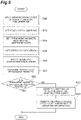
- the reading device reads the identification code 20 of a stack 10 and the respective identification codes 21 and 22 of a lower die 151 and an upper die 152 to be attached to this stack 10 (see step S20 in FIG. 9 ).
- the controller Ctr stores, in a recording medium, information that associates the stack 10 with the lower die 151 and the upper die 152 to be attached to the stack 10.
- the respective processes at steps S13 to S16 already described are performed, whereby a stacked rotor core 1 is manufactured.
- the stacked rotor core 1 is attached to the depth detecting unit 180.
- the stacked rotor core 1 is placed onto the base member 181 such that the insertion post 182 has been inserted into the shaft hole 10a and the respective protrusions 183 are positioned in the corresponding depressions 14a.
- the depth detecting unit 180 the depths of the respective depressions 14a of the stacked rotor core 1 are measured (see step S21 in FIG. 9 ). For example, it is determined whether the contact sensor 184 is in contact with the stack 10.
- the controller Ctr determines that the positions of the permanent magnets 12 in the magnet insertion hole 16 are located at height positions of the protrusions 151c. Thus, manufacturing of the stacked rotor core 1 is completed.
- the controller Ctr determines that the positions of the permanent magnets 12 in the magnet insertion hole 16 are not located at the height positions of the protrusions 151c. In this case, the depths of the depressions 14a have become shallower, whereby the stacked rotor core 1 attached to the depth detecting unit 180 is suspended apart from the base member 181.
- Such shallower depths are caused by wear of the protrusions 151c of the lower die 151, or caused by presence of melted resin that has entered between each protrusion 151c and the corresponding permanent magnet 12 (see FIG. 8B ) due to extraneous substances or the like adhering to the lower die 151 when the melted resin has been injected into the magnet insertion holes 16 at step S16, for example.
- the reading device In the noncontact state, based on instruction signals from the controller Ctr, the reading device reads the identification code 20 of the stacked rotor core 1 again.
- the controller Ctr identifies a lower die 151 used for manufacturing this stacked rotor core 1 on the basis of the identification code 21 associated with the read identification code 20 (see step S23 in FIG. 9 ). Subsequently, this stacked rotor core 1 and the identified lower die 151 are removed from the magnet mounting device 140 (see step S24 in FIG. 9 ).
- the respective processes at steps S21 to S24 described above may be performed on an upper die 152.
- a stacked rotor core 1 turned upside down may be attached to the depth detecting unit 180, and the protrusions 183 may be positioned in the respective depressions 14a formed by the protrusions 152b of the upper die 152.
- the depth detecting unit 180 detects the depths of depressions 14a after manufacturing of a stacked rotor core 1.
- the actual positions of the permanent magnets 12 in the magnet insertion holes 16 can be determined. Consequently, by detecting the depths of the depressions 14a after manufacturing of the stacked rotor core 1, the permanent magnets 12 can be reliably positioned in the magnet insertion holes 16 more accurately.
- the depth detecting unit 180 in the modified embodiment (1) above may be a contact-type or noncontact-type depth sensor as depicted in FIGS. 10A and 10B . If the depths of depressions 14a detected by the depth detecting unit 180 are within a set range (see FIG. 10A ), the controller Ctr determines that the positions of the permanent magnets 12 in the magnet insertion holes 16 are located at height positions of the protrusions 151c. If the depths of depressions 14a detected by the depth detecting unit 180 are out of the set range (see FIG. 10B ), the controller Ctr determines that the positions of the permanent magnets 12 in the magnet insertion holes 16 are not located at the height positions of the protrusions 151c. According to the modified embodiment (2), by using a commercially available contact-type or noncontact-type depth sensor, positioning accuracy of the permanent magnets 12 in the magnet insertion holes 16 can be reliably obtained.
- Embodiment (3) The modified embodiment (1) or (2) may be combined with other examples disclosed herein.
- the respective protrusions 151c and 152b of the lower die 151 and the upper die 152 may be detected by the height detecting unit 162
- the depths of the depressions 14a may be detected by the depth detecting unit 180.
- the lower die 151 may further include pairs of protrusions 151d (second projecting portions) and pairs of protrusions 151e (second projecting portions) in addition to the protrusions 151c.
- the protrusions 151d and 151e protrude upward from the upper surface of the base member 151a.
- the protrusions 151d and 151e each have a columnar shape. As depicted in FIG. 11A , distal end portions of the protrusions 151d and 151e may be reduced in diameter toward the distal ends.
- Each pair of protrusions 151d is positioned with a corresponding protrusion 151c interposed therebetween.
- the corresponding pair of protrusions 151e is positioned with the same protrusion 151c interposed therebetween. In other words, this one protrusion 151c is positioned at a central portion of these protrusions 151d and 151e.
- the pair of protrusions 151d and the pair of protrusions 151e are positioned in a corresponding magnet insertion hole 16 together with the one protrusion 151c surrounded by these protrusions 151d and 151e.
- the opposing direction of the pair of protrusions 151d and the opposing direction of the pair of protrusions 151e intersect each other.
- the separation distance between the pair of protrusions 151d is substantially the same as the width of each permanent magnet 12 in the lateral direction.
- the separation distance between the pair of protrusions 151e is substantially the same as the width of the permanent magnet 12 in the longitudinal direction.
- each permanent magnet 12 is sandwiched by a pair of protrusions 151d and a pair of protrusions 151e.
- movement of the permanent magnet 12 is restricted in the opposing direction of the pair of protrusions 151d and the opposing direction of the pair of protrusions 151e. Consequently, the permanent magnet 12 can be positioned not only in the height direction, but also in the horizontal direction.
- the distal end portions of the protrusions 151d and 151e are reduced in diameter toward the distal ends, the lower end portion of the permanent magnet 12 can be easily guided to the inside between the protrusions 151d and 151e.
- the lower die 151 may include at least one pair of protrusions 151d and at least one pair of protrusions 151e.
- the upper die 152 also may include protrusions corresponding to the protrusions 151d and 151e.
- the lower die 151 may further include pairs of protrusions 151d (second projecting portions) and pairs of protrusions 151e (second projecting portions) instead of the protrusions 151c.
- these protrusions 151d and 151e each have a conical shape.
- an area surrounded by each pair of protrusions 151d and the corresponding pair of protrusions 151e becomes smaller toward the base member 151a.
- the lower die 151 may include at least one pair of protrusions 151d and at least one pair of protrusions 151e.
- the upper die 152 also may include protrusions corresponding to the protrusions 151d and 151e.
- the lower die 151 may include the protrusions 151c.
- Embodiment (6) At least the lower die 151 includes the protrusions 151c. In other words, the upper die 152 may not include the protrusions 152b. In this case, in a manufactured stacked rotor core 1, no depression 14a is formed on the upper end side of each permanent magnet 12, and the corresponding solidified resin 14 covers this upper end portion of the permanent magnet 12.
- the lower die 151 may include projecting portions having forms other than that of the columnar protrusions 151c.
- the lower die 151 may include projecting portions protruding from a surface of the base member 151a, and each projecting portion may have a groove corresponding to a corner of the corresponding permanent magnet 12.
- a stack 10 is attached to a lower die 151, permanent magnets 12 are inserted into the respective magnet insertion holes 16.
- a stack 10 in the state where the permanent magnets 12 have been inserted into the respective magnet insertion holes 16 may be attached to the lower die 151.
- One set of magnets consisting of two or more permanent magnets 12 in combination may each be inserted into each magnet insertion hole 16.
- a plurality of permanent magnets 12 may be aligned in the longitudinal direction of the magnet insertion hole 16.
- a plurality of permanent magnets 12 may be aligned in the lengthwise direction of the magnet insertion hole 16.
- a plurality of permanent magnets 12 may be aligned in the longitudinal direction, and simultaneously a plurality of permanent magnets 12 may be aligned in the lengthwise direction.
- a stack 10 formed by stacking a plurality of blanked members W serves as a core body to which permanent magnets 12 are attached.
- the core body may be formed of components other than the stack 10.
- the core body may be formed by compression molding ferromagnetic powder, or may be formed by injection molding resin material containing ferromagnetic powder.
- melted resin is injected into magnet insertion holes 16 from the upper die 152 side.
- the melted resin may be injected into the magnet insertion holes 16 from the lower die 151 side.
- the melted resin may be injected into the magnet insertion holes 16 from both of the lower die 151 side and the upper die 152 side.
- a cull plate may be disposed between the lower die 151 and the stack 10.
- a cull plate may be disposed between the upper die 152 and the stack 10.
- a resin flow path e.g., a runner, a gate hole
- the resin flow path may be formed on an opposing surface of the upper die 152 opposed to the stack 10.
- the resin flow path may be formed on an opposing surface of the lower die 151 opposed to the stack 10.
- the lower die used when one rotor core is manufactured may also be used for manufacturing another rotor core.
- repeated use of a lower die in manufacturing of a rotor core gradually wears a first projecting portion formed on the lower die, or damages the first projecting portion due to its small size. Such small wear or damage, even though it is hard to be found by a visual check, will change the position of a permanent magnet in a magnet insertion hole.
- the height of the first projecting portion formed on the lower die is detected by the height detecting unit, and the subsequent processes are performed when the height of the first projecting portion is within the set range.
- the permanent magnet being in contact with the first projecting portion, the melted resin is injected into the magnet insertion hole to be solidified therein, whereby the position of the permanent magnet in the magnet insertion hole is reliably located at a height position of the first projecting portion detected in advance. Consequently, only through a process of detecting the height of the first projecting portion in advance, positioning accuracy of the permanent magnet in the magnet insertion hole can be reliably obtained.
- a pair of second projecting portions may be formed on the lower die, and placing the core body onto the lower die may include placing the core body onto the lower die such that the first projecting portion and the pair of second projecting portions are positioned in the magnet insertion hole. Additionally, inserting the permanent magnet into the magnet insertion hole may include inserting the permanent magnet into the magnet insertion hole such that the permanent magnet comes into contact with the upper end of the first projecting portion and the permanent magnet is sandwiched by the pair of second projecting portions. In this case, the permanent magnet is sandwiched by the pair of second projecting portions, whereby movement of permanent magnet in the opposing direction of the pair of second projecting portions is restricted.
- the permanent magnet can be positioned not only in the height direction, but also in the horizontal direction.
- a third projecting portion may be formed on the holding member, and placing the holding member onto the core body may include bringing the permanent magnet in the magnet insertion hole into contact with a lower end of the third projecting portion.
- the permanent magnet when the melted resin is injected into the magnet insertion hole, the permanent magnet is sandwiched by the first projecting portion of the lower die and the third projecting portion of the holding member.
- movement of the permanent magnet in the height direction is restricted by the first and third projecting portions. Consequently, the position of the permanent magnet in the magnet insertion hole can be determined accurately.
- the method may further include removing the lower die and the holding member from the core body after injecting the melted resin into the magnet insertion hole to form a depression on a lower end portion of a solidified resin formed by solidifying the melted resin, the lower end portion corresponding to the first projecting portion, and detecting a depth of the depression by a depth detecting unit.
- the depth detecting unit detects the depth of the depression.
- the depth detecting unit may include a base member, a fourth projecting portion formed on the base member, and a contact sensor formed on the base member. Additionally, detecting the depth of the depression by the depth detecting unit may include detecting by the contact sensor whether the core body is in contact with the contact sensor when the fourth projecting portion is positioned in the depression. In this case, by setting the height of the fourth projecting portion to be equal to the height of the first projecting portion, the positioning accuracy of the permanent magnet in the magnet insertion hole can be reliably obtained on the basis of ON/OFF conditions of the contact sensor.
- the depth detecting unit may be a depth sensor configured to be capable of directly measuring the depth of the depression. In this case, by using a commercially available contact-type or noncontact-type depth sensor, the positioning accuracy of the permanent magnet in the magnet insertion hole can be reliably obtained.
- the present disclosure further relates to a method for manufacturing a metal product.
- Said method includes conveying a core body to a magnet mounting device, mounting, in the magnet mounting device, a plurality of permanent magnets into a plurality of magnet insertion holes of the core body, wherein the magnet insertion holes are passing through the core body in a height direction along the central axis, wherein the magnet mounting device includes a resin charging mechanism and a depth detection unit, wherein the resin charging mechanism includes a lower die and a holding member, wherein the lower die includes a plurality of first projecting portions, wherein mounting the magnets into the magnet insertion holes includes the following steps: placing the core body onto the lower die such that the first projecting portions formed on the lower die are positioned in the magnet insertion holes; bringing the permanent magnets in the magnet insertion holes into contact with upper ends, in the height direction, of the first projecting portions; placing the holding member onto the core body after bringing the permanent magnets into contact with the upper ends of the first projecting portions, wherein the holding member
- the lower die used when one rotor core is manufactured may also be used for manufacturing another rotor core.
- the repeated use of a lower die in manufacturing of a rotor core gradually wears a first projecting portion formed on the lower die. Such small wear, even though it is hard to be found by a visual check, will change the position of a permanent magnet in a magnet insertion hole.
- the depth detecting unit may detect the depth of the depression after manufacturing of the rotor core.
- the actual position of the permanent magnet in the magnet insertion hole can be determined. Consequently, through a process of detecting the depth of the depression after manufacturing of the rotor core, positioning accuracy of the permanent magnet in the magnet insertion hole can be reliably obtained.
- a pair of second projecting portions may be formed on the lower die, and placing the core body onto the lower die may include placing the core body onto the lower die such that the first projecting portion and the pair of second projecting portions are positioned in the magnet insertion hole. Additionally, inserting the permanent magnet into the magnet insertion hole may include inserting the permanent magnet into the magnet insertion hole such that the permanent magnet comes into contact with the upper end of the first projecting portion and the permanent magnet is sandwiched by the pair of second projecting portions to obtain the same or similar functionality as those of the method described above.
- a third projecting portion may be formed on the holding member, and placing the holding member onto the core body may include bringing the permanent magnet in the magnet insertion hole into contact with a lower end of the third projecting portion to obtain the same or similar functionality as those of the method described above.
- the depth detecting unit may include a base member, a fourth projecting portion formed on the base member, and a contact sensor formed on the base member. Additionally, detecting whether the depth of the depression is within the set range by the depth detecting unit may include detecting by the contact sensor whether the core body is in contact with the contact sensor when the fourth projecting portion is positioned in the depression to obtain the same or similar functionality as those of the method described above.
- the depth detecting unit may be a depth sensor configured to be capable of directly measuring the depth of the depression to obtain the same or similar functionality as those of the method described above.
Landscapes
- Engineering & Computer Science (AREA)
- Power Engineering (AREA)
- Manufacturing & Machinery (AREA)
- Physics & Mathematics (AREA)
- General Physics & Mathematics (AREA)
- Permanent Field Magnets Of Synchronous Machinery (AREA)
- Manufacture Of Motors, Generators (AREA)
- Iron Core Of Rotating Electric Machines (AREA)
Description
- This application generally relates to a method for manufacturing a rotor core.
- A rotor core commonly includes: a core body in which a plurality of magnet insertion holes passing through the core body in a height direction thereof are formed around the rotation axis at predetermined intervals; permanent magnets disposed in the respective magnet insertion holes; and solidified resins charged into the respective magnet insertion holes and solidified therein. In order to promote the injection of melted resin into the magnet insertion holes and adjust the weight balance of the rotor core, for example, positions of the permanent magnets in the magnet insertion holes may be controlled.
-
Japanese Unexamined Patent Publication No. 2015-192573 -
WO 2012/026003 A1 describes a magnet-embedded rotor. Therotor 15 has: ahollow shaft 11 that is rotatably supported by abearing 13 that is affixed to a case; a laminatedcore 12 wherein thin plate-shaped magnetic bodies are laminated; a endplate 16 (plate member) that presses the laminatedcore 12 from both sides; apermanent magnet 14 that is inserted into a through-hole provided to the laminatedcore 12; molding resin 17 that fills the space between the through-hole and thepermanent magnet 14; and amolding hole 18 formed on one side of the laminated core. Themolding hole 18 is formed using a stopper (installed in order to set a predetermined amount of insetting) that is on the order of about 0.2 mm to about 1 mm from the side surface of the laminated core. - However, in
Japanese Unexamined Patent Publication No. 2015-192573 - In view of this, this disclosure describes a method for manufacturing a rotor core that enables positioning accuracy of permanent magnets in magnet insertion holes to be reliably obtained with great ease.
- The present invention is defined in the claims. A method for manufacturing a rotor core according to one aspect of the present disclosure includes conveying a core body to a magnet mounting device, mounting, in the magnet mounting device, a plurality of permanent magnets into a plurality of magnet insertion holes of the core body, wherein the magnet insertion holes are passing through the core body in a height direction, along the central axis, wherein the magnet mounting device includes a resin charging mechanism and a detection mechanism, wherein the resin charging mechanism includes a lower die and a holding member, wherein the lower die includes a plurality of first projecting portions, wherein the detection mechanism includes a height detecting unit, wherein mounting the magnets into the magnet insertion holes includes the following steps: detecting, by the height detecting unit, heights of the first projecting portions formed on the lower die; placing the core body onto the lower die such that the first projecting portions are positioned in the magnet insertion holes when the height detecting unit has determined that the heights of the first projecting portions are within a set range; bringing the permanent magnets in the magnet insertion holes into contact with upper ends, in the height direction of the first projecting portions; placing the holding member onto the core body after bringing the permanent magnets into contact with the upper ends of the first projecting portions, wherein the holding member is configured to hold the core body with the lower die and to sandwich the core body with the lower die in the height direction, after placing the holding member onto the core body, injecting melted resin into the magnet insertion holes in which the permanent magnets have been inserted for producing the rotor core; and after injecting melted resin into the magnet insertion holes, removing the lower die and the holding member from the rotor core and conveying the lower die to the height detecting unit in order to produce another rotor core.
- A method for manufacturing of a rotor core according to another aspect of the present disclosure includes conveying a core body to a magnet mounting device, mounting, in the magnet mounting device, a plurality of permanent magnets into a plurality of magnet insertion holes of the core body, wherein the magnet insertion holes are passing through the core body in a height direction along the central axis, wherein the magnet mounting device includes a resin charging mechanism and a depth detection unit, wherein the resin charging mechanism includes a lower die and a holding member, wherein the lower die includes a plurality of first projecting portions, wherein mounting the magnets into the magnet insertion holes includes the following steps: placing the core body onto the lower die such that the first projecting portions formed on the lower die are positioned in the magnet insertion holes; bringing the permanent magnets in the magnet insertion holes into contact with upper ends, in the height direction, of the first projecting portions; placing the holding member onto the core body after bringing the permanent magnets into contact with the upper ends of the first projecting portions, wherein the holding member is configured to hold the core body with the lower die and to sandwich the core body with the lower die in the height direction, after placing the holding member onto the core body, injecting melted resin into the magnet insertion holes in which the permanent magnets have been inserted for producing the rotor core; after injecting the melted resin into the magnet insertion holes, removing the lower die and the holding member from the rotor core to form depressions on lower end portions of a plurality of solidified resins formed by solidifying the melted resin, the lower end portions corresponding to the first projecting portions, detecting, by the depth detecting unit, whether the depths of the depressions are within a set range; and conveying the lower die in order to produce another rotor core.
- By the methods for manufacturing a rotor core according to the present disclosure, positioning accuracy of the permanent magnet in the magnet insertion hole can be reliably obtained with great ease.
-
-
FIG. 1 is a perspective view illustrating an example stacked rotor core as manufactured by the method of the present invention; -
FIG. 2 is a sectional view taken along line II-II inFIG. 1 ; -
FIG. 3 is a schematic diagram illustrating a manufacturing device that may be used for manufacturing the stacked rotor core manufactured according to the method of the present invention; -
FIG. 4 is a perspective view illustrating a resin charging mechanism; -
FIG. 5 is a schematic diagram illustrating part of a magnet mounting device; -
FIG. 6 is a schematic diagram illustrating part of the magnet mounting device; -
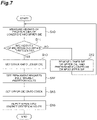
FIG. 7 is a flowchart illustrating an example according to the claimed invention of a method for manufacturing a stacked rotor core; -
FIG. 8A and FIG. 8B are schematic diagrams illustrating an example according to the claimed invention of position measurement of permanent magnets; -
FIG. 9 is a flowchart illustrating another example according to the claimed invention of a method for manufacturing a stacked rotor core; -
FIG. 10A and FIG. 10B are schematic diagrams illustrating another example according to the claimed invention of position measurement of permanent magnets; and -
Fig. 11A is a perspective view illustrating an example of the lower die according to the claimed invention. -
Fig. 11B is a perspective view illustrating an example of the lower die not covered by the scope of the claimed invention. - In the following description, with reference to the drawings, the same reference numbers are assigned to the same components or to similar components having the same function, and overlapping description is omitted.
- With reference to
FIG. 1 andFIG. 2 , a configuration of a stacked rotor core 1 (rotor core) will be described first. The stackedrotor core 1 is part of a rotor. By attaching end plates and a shaft to the stackedrotor core 1, a rotor is formed. By assembling the rotor with a stator, a motor is formed. The stacked rotor core 1may be used for an interior permanent magnet (IPM) motor. As depicted inFIG. 1 , thestacked rotor core 1 includes a stack 10 (core body), a plurality ofpermanent magnets 12, a plurality ofsolidified resins 14, and anidentification code 20. - The
stack 10 has a cylindrical shape as depicted inFIG. 1 . For example, in a central portion of thestack 10, ashaft hole 10a that passes through thestack 10 so as to extend along a central axis Ax thereof is formed. In other words, theshaft hole 10a extends in a height direction (stacking direction) of thestack 10. The height direction is also the lengthwise direction of the central axis Ax. InFIG. 1 , thestack 10 is rotated about the central axis Ax, and thus the central axis Ax is also a rotation axis. A shaft may be inserted into theshaft hole 10a. - In the
stack 10, a plurality ofmagnet insertion holes 16 are formed. As depicted inFIG. 1 , themagnet insertion holes 16 are aligned along the outer periphery of thestack 10 at predetermined intervals. As depicted inFIG. 2 , themagnet insertion holes 16 pass through thestack 10 so as to extend along the central axis Ax. In other words, themagnet insertion holes 16 extend in the height direction. - Each
magnet insertion hole 16 may have the shape of a long hole extending along the outer periphery of thestack 10. The number of themagnet insertion holes 16 is six in the stackedrotor core 1 ofFIG. 1 . The positions, the shapes, and the number of themagnet insertion holes 16 may be changed based on intended use and required performance, for example, of the motor. - The
stack 10 is formed by stacking a plurality of blanked members W. Each blanked member W is a plate-like member obtained by blanking an electromagnetic steel sheet ES described later in a predetermined shape, and has a shape corresponding to the shape of thestack 10. Thestack 10 may be formed by a rotational stack. The term "rotational stack" means stacking a plurality of blanked members W while displacing the angles between the blanked members W relative to one another. The rotational stack is performed mainly for the purpose of offsetting the deviation in plate thickness of the blanked members W. The angle of the rotational stack may be set at any angle. - Blanked members W adjacent in the height direction may be fastened together by interlocking
portions 18 as depicted inFIG. 1 andFIG. 2 . These blanked members W may be fastened together by various known methods instead of the interlockingportions 18. For example, the blanked members W may be bonded together with adhesive or resin material, or may be bonded together by welding. Alternatively, a temporarily-interlocking portion may be formed on each blanked member W, the blanked members W may be fastened together by the temporarily-interlocking portions to form astack 10, and then the temporarily-interlocking portions may be removed from this stack. The term "temporarily-interlocking portion" means a swaged area that is used to temporarily integrate a plurality of blanked members W together and is removed in a process of manufacturing a product (stacked rotor core 1). - The
permanent magnets 12 have been inserted into the respective magnet insertion holes 16 one by one as depicted inFIG. 1 andFIG. 2 . The shape of eachpermanent magnet 12 may have, but is not limited to, a rectangular parallelepiped shape. The type of thepermanent magnet 12 may be determined based on intended use and required performance, for example, of the motor, and may be a sintered magnet or a bond magnet, for example. - Each solidified
resin 14 is a resin formed by charging melted resin material (melted resin) into the magnet insertion holes 16 into which thepermanent magnets 12 have been inserted and then solidifying the melted resin. The solidified resins 14 have a function of fixing thepermanent magnets 12 in the magnet insertion holes 16 and a function of bonding the blanked members W adjacent in the height direction (vertical direction) to each other. Examples of resin material forming each solidifiedresin 14 include a thermosetting resin and a thermoplastic resin. Specific examples of the thermosetting resin include resin compositions containing an epoxy resin, a curing initiator, and an additive. Examples of the additive include a filler, a flame retardant, and a stress-lowering agent. - As depicted in
FIG. 1 andFIG. 2 , in an upper end portion and a lower end portion of each solidifiedresin 14,columnar depressions 14a are formed. From bottom surfaces of thedepressions 14a, thepermanent magnets 12 are exposed. Eachpermanent magnet 12 may be positioned between the corresponding pair ofdepressions 14a and in a midpoint of the correspondingmagnet insertion hole 16 in the height direction. - The
identification code 20 is provided on a surface (an upper surface or a lower surface) of thestack 10, that is, an outer surface of a blanked member W in the uppermost layer or the lowermost layer of thestack 10. Theidentification code 20 has a function of storing and/or identifying individual information (e.g., product type, date and time of manufacture, used material, manufacturing line) of the stackedrotor core 1 including theidentification code 20. Theidentification code 20 is not limited to a particular type of information, and can be used to store the individual information by a combination of light and dark patterns, and may be a bar code or may be a two-dimensional code, for example. Examples of the two-dimensional code include QR code (registered trademark), DataMatrix, and Vericode. As depicted inFIG. 1 , theidentification code 20 may form a predetermined pattern with a combination of a white background area and a black marking. - The following describes a
manufacturing device 100 for the stackedrotor core 1 with reference toFIG. 3 . - The
manufacturing device 100 is a device configured to manufacture the stackedrotor core 1 from an electromagnetic steel sheet ES (sheet to be processed) that is a belt-like metal sheet. Themanufacturing device 100 includes anuncoiler 110, afeeder 120, ablanking device 130, amagnet mounting device 140, and a controller Ctr (control unit). - The
uncoiler 110 rotatably supports acoiled material 111 that is a belt-like electromagnetic steel sheet ES wound in a coiled shape, with thecoiled material 111 being mounted thereon. Thefeeder 120 has a pair ofrollers rollers blanking device 130 in sequence. - The
blanking device 130 operates in response to instruction signals from the controller Ctr. Theblanking device 130 has a function of forming the blanked members W by blanking the electromagnetic steel sheet ES that is intermittently fed by thefeeder 120 and a function of manufacturing astack 10 by stacking blanked members W obtained by the blanking. - After being discharged from the
blanking device 130, thestack 10 is placed on a conveyor Cv that is provided in a manner extending between the blankingdevice 130 and themagnet mounting device 140. The conveyor Cv operates in response to instruction signals from the controller Ctr to feed thestack 10 to themagnet mounting device 140. Herein, between the blankingdevice 130 and themagnet mounting device 140, thestack 10 may be conveyed by means other than the conveyor Cv. For example, thestack 10 may be manually conveyed while being placed in a container. - The
magnet mounting device 140 operates in response to instruction signals from the controller Ctr. Themagnet mounting device 140 has a function of inserting thepermanent magnets 12 into the respective magnet insertion holes 16 and a function of charging melted resin into the magnet insertion holes 16 into which thepermanent magnets 12 have been inserted. - The controller Ctr generates, for example, based on a program recorded in a recording medium (not depicted) or operation inputs from an operator, the respective instruction signals for causing each of the
feeder 120, theblanking device 130, and themagnet mounting device 140 to operate, and transmits the respective instruction signals to thefeeder 120, theblanking device 130, and themagnet mounting device 140. - The following describes details of the
magnet mounting device 140 with reference toFIG. 4 to FIG. 6 . Themagnet mounting device 140 includes aresin charging mechanism 150, adetection mechanism 160, and aconveyance mechanism 170. - As depicted in
FIG. 4 , theresin charging mechanism 150 includes alower die 151, an upper die 152 (holding member), and a plurality ofplungers 153. Thelower die 151 includes abase member 151a, aninsertion post 151b formed on thebase member 151a, and a plurality of protrusions (first projecting portions) 151c formed on thebase member 151a. - The
base member 151a may be a plate-like member having a rectangular shape. Thebase member 151a is formed so that astack 10 can be placed thereon. On an upper surface of thebase member 151a, anidentification code 21 is provided. The configuration of theidentification code 21 is similar to that of theidentification code 20 provided on thestack 10. For example, theidentification code 21 has a function of storing individual information for identifying anindividual base member 151a (lower die 151) provided with thisidentification code 21. - The
insertion post 151b is positioned at a substantially central portion of thebase member 151a, and protrudes upward from the upper surface of thebase member 151a. Theinsertion post 151b has a columnar shape, having an outer shape corresponding to the shape of theshaft hole 10a of thestack 10. - The
protrusions 151c are aligned along the periphery of theinsertion post 151b at predetermined intervals. When astack 10 is placed on thebase member 151a, therespective protrusions 151c are located at positions corresponding to the respective magnet insertion holes 16 of thestack 10. Theprotrusions 151c protrude upward from the upper surface of thebase member 151a. Eachprotrusion 151c has a columnar shape, having a shape corresponding to the shape of thedepression 14a of each solidifiedresin 14. - The
upper die 152 is formed so as to be able to hold astack 10 with thelower die 151 in the height direction. As depicted inFIG. 4 andFIG. 6 , theupper die 152 includes abase member 152a, a plurality of protrusions (third projecting portions) 152b formed on thebase member 152a, and an internal heat source (e.g., a heater embedded in thebase member 152a) (not depicted). - The
base member 152a may be a plate-like member having a rectangular shape. On an upper surface of thebase member 152a, anidentification code 22 is provided. The configuration of theidentification code 22 is similar to those of theidentification codes stack 10 and thelower die 151. For example, theidentification code 22 has a function of storing individual information for identifying anindividual base member 152a (upper die 152) provided with thisidentification code 22. - One through
hole 152c, a plurality of accommodatingdepressions 152d, and a plurality ofgate holes 152e are formed in thebase member 152a. The throughhole 152c is positioned at a substantially central portion of thebase member 152a. The throughhole 152c has a shape (substantially circular shape) corresponding to the shape of theinsertion post 151b, and theinsertion post 151b can be inserted therein.. - The
accommodating depressions 152d are aligned, on the upper surface side of thebase member 152a, along the periphery of the throughhole 152c at predetermined intervals. Thus, openings of the respectiveaccommodating depressions 152d are open to the upper surface side of thebase member 152a. When astack 10 is sandwiched by thelower die 151 and theupper die 152, the respectiveaccommodating depressions 152d are located at positions corresponding to the respective magnet insertion holes 16 of thestack 10. Eachaccommodating depression 152d has a columnar shape, and has a function of accommodating at least one resin pellet P. When theupper die 152 is heated by the internal heat source of theupper die 152, the resin pellets P accommodated in the respectiveaccommodating depressions 152d are melted to become melted resin. - The
gate holes 152e are aligned, on the lower surface side of thebase member 152a, along the periphery of the throughhole 152c at predetermined intervals. Thus, openings of therespective gate holes 152e are open to the lower surface side of thebase member 152a. When astack 10 is sandwiched by thelower die 151 and theupper die 152, therespective gate holes 152e are located at positions corresponding to the respective magnet insertion holes 16 of thestack 10. Therespective gate holes 152e communicate with the correspondingaccommodating depressions 152d in the height direction. This enables the melted resin in theaccommodating depressions 152d to flow into thegate holes 152e. Thus, theaccommodating depressions 152d and thegate holes 152e serve as flow paths for injecting resin into the magnet insertion holes 16. - The
protrusions 152b are aligned along the periphery of the throughhole 152c at predetermined intervals. When astack 10 is sandwiched by thelower die 151 and theupper die 152, therespective protrusions 152b are located at positions corresponding to the respective magnet insertion holes 16 of thestack 10. Theprotrusions 152b protrude downward from a lower surface of thebase member 152a. Eachprotrusion 152b has a columnar shape, having a shape corresponding to the shape of thedepression 14a of each solidifiedresin 14. - The
plungers 153 are positioned above theupper die 152. Therespective plungers 153 are configured to be capable of being inserted into and removed from the correspondingaccommodating depressions 152d by a drive source (not depicted). - The
detection mechanism 160 includes a rotating table 161 and aheight detecting unit 162 as depicted inFIG. 5 . The rotating table 161 is configured to be capable of being rotated about its rotation axis by a drive source (not depicted). Alower die 151 conveyed by theconveyance mechanism 170 is placed one by one onto the rotating table 161. - The
height detecting unit 162 is configured to detect the height of eachprotrusion 151c of thelower die 151 placed on the rotating table 161. Theheight detecting unit 162 may be a contact-type sensor, or may be a noncontact-type sensor. Theheight detecting unit 162 may have a function of directly detecting the height of eachprotrusion 151c, or may have a function of detecting the height of theprotrusion 151c on the basis of the difference between the upper end surface of theprotrusion 151c and the upper surface of thebase member 151a. When thelower die 151 on the rotating table 161 is rotated together with the rotating table 161, theprotrusions 151c can be sequentially detected by thisheight detecting unit 162 alone. - The
conveyance mechanism 170 is positioned downstream of thedetection mechanism 160 and the conveyor Cv. Thus, astack 10 conveyed by the conveyor Cv and alower die 151 conveyed from thedetection mechanism 160 are fed onto a portion of theconveyance mechanism 170 on its upstream side. Theconveyance mechanism 170 has a function of intermittently conveying downstream alower die 151 to which astack 10 is attached and a function of conveying thelower die 151 so as to return only thelower die 151 to the rotating table 161. In other words, thelower die 151 is conveyed so as to circulate between the detection mechanism 160 (rotating table 161) and theconveyance mechanism 170. Theconveyance mechanism 170 may include a conveyor and conveyance rollers. - An example according to the claimed invention of a method for manufacturing a stacked
rotor core 1 is described with reference toFIG. 5 to FIG. 7 . Herein, description of a process of forming astack 10 by theblanking device 130 is omitted, and the subsequent processes will be described. - To begin with, a
lower die 151 that has been previously used to produce astacked rotor core 1 is conveyed by theconveyance mechanism 170 to the rotating table 161, and is placed onto the rotating table 161. Placement of thelower die 151 onto the rotating table 161 may be performed manually, or may be performed by a transfer device (e.g., a robot hand, not depicted) in response to instructions of the controller Ctr. In this state, the controller Ctr issues instructions to the rotating table 161 and theheight detecting unit 162 to cause theheight detecting unit 162 to sequentially measure the heights of theprotrusions 151c formed on thelower die 151 that is being rotated by the rotating table 161 (see section (a) inFIG. 5 and step S10 inFIG. 7 ). - Although not depicted in
FIG. 5 , the heights of theprotrusions 152b of anupper die 152 are also measured by theheight detecting unit 162 in a manner similar to that for theprotrusions 151c of thelower die 151. In other words, the heights of theprotrusions 152b formed on theupper die 152 that is placed on the rotating table 161 and is being rotated are sequentially measured by the height detecting unit 162 (see step S10 inFIG. 7 ). - When receiving data of the heights of the
respective protrusions height detecting unit 162, the controller Ctr determines whether the heights of therespective protrusions FIG. 7 ). As a result of the determination of the controller Ctr at step S11, if even one of the heights of therespective protrusions FIG. 7 ), alower die 151 or anupper die 152 having aprotrusion magnet mounting device 140, and a new lower die 151 or a newupper die 152 is prepared (see step S12 inFIG. 7 ). - As a result of the determination of the controller Ctr at step S11, if all the
protrusions FIG. 7 ), thelower die 151 is conveyed to theconveyance mechanism 170, and is placed onto the conveyance mechanism 170 (see section (b) inFIG. 5 ). Subsequently, astack 10 conveyed by the conveyor Cv from theblanking device 130 is attached to thelower die 151 placed on the conveyance mechanism 170 (see section (b) inFIG. 5 and step S13 inFIG. 7 ). For example, thestack 10 is placed onto the lower die 151 (base member 151a) such that theinsertion post 151b is inserted into theshaft hole 10a of thestack 10 and therespective protrusions 151c are positioned in the corresponding magnet insertion holes 16. Placement of thelower die 151 onto theconveyance mechanism 170 and placement of thestack 10 onto thelower die 151 may be performed manually, or may be performed by a transfer device (e.g., a robot hand, not depicted) in response to instructions of the controller Ctr. - Subsequently, after the
conveyance mechanism 170 intermittently conveys thelower die 151 downstream in response to instructions of the controller Ctr,permanent magnets 12 are inserted into the respective magnet insertion holes 16 of thestack 10 one by one (see section (c) inFIG. 5 and step S14 inFIG. 7 ). At this time, lower end surfaces of thepermanent magnets 12 inserted into the magnet insertion holes 16 come into contact with the upper ends of theprotrusions 151c, respectively. Insertion of thepermanent magnets 12 into the respective magnet insertion holes 16 may be performed manually, or may be performed by an inserting device (e.g., a robot hand, not depicted) in response to instructions of the controller Ctr. - Subsequently, after the
conveyance mechanism 170 intermittently conveys thelower die 151 downstream in response to instructions of the controller Ctr, and after having been determined that the heights of all theprotrusions 152b of theupper die 152 are within the threshold at step S11, anupper die 152 is attached to the stack 10 (see section (d) inFIG. 6 and step S15 inFIG. 7 ). At this time, theupper die 152 is placed onto thestack 10 such that theinsertion post 151b is inserted into the throughhole 152c and therespective protrusions 152b are positioned in the corresponding magnet insertion holes 16. Thus, thestack 10 is sandwiched by thelower die 151 and theupper die 152 in the height direction. The lower ends of theprotrusions 152b inserted into the magnet insertion holes 16 come into contact with the upper end surfaces of thepermanent magnets 12, respectively, and thus thepermanent magnets 12 are sandwiched by theprotrusions accommodating depressions 152d and the gate holes 152e that are flow paths for injecting resin communicate with the corresponding magnet insertion holes 16. - Subsequently, resin pellets P are charged into the respective
accommodating depressions 152d. When the resin pellets P have been melted by the internal heat source of theupper die 152, this melted resin is injected by theplungers 153 into the respective magnet insertion holes 16 (see section (e) inFIG. 6 and step S16 inFIG. 7 ). Subsequently, the melted resin is cooled to be solidified, whereby solidifiedresins 14 are formed in the magnet insertion holes 16. When thelower die 151 and theupper die 152 have been removed from thestack 10, astacked rotor core 1 is completed (see section (f) inFIG. 6 ). - Example processes according to the claimed invention disclosed herein may be performed before a
stack 10 is placed onto alower die 151, the heights of theprotrusions 151c formed on thelower die 151 are detected by theheight detecting unit 162, and if the heights of all theprotrusions 151c are within a threshold. Thus, with thepermanent magnets 12 being in contact with theprotrusions 151c, melted resin is injected into the magnet insertion holes 16 to be solidified therein, such that it may be detected in advance that the positions of thepermanent magnets 12 in the magnet insertion holes 16 are reliably located at height positions of theprotrusions 151c. Consequently, by detecting the heights of theprotrusions 151c in advance, positioning accuracy of thepermanent magnets 12 in the magnet insertion holes 16 can be reliably obtained. - In some examples of the claimed invention, , before an
upper die 152 is placed onto astack 10, the heights of theprotrusions 152b formed on theupper die 152 are detected by theheight detecting unit 162, and if the heights of all theprotrusions 152b are within the threshold, the subsequent processes are performed. Thus, when melted resin is injected into the magnet insertion holes 16, thepermanent magnets 12 are sandwiched by theprotrusions 151c of thelower die 151 and theprotrusions 152b of theupper die 152. Thus, movement of thepermanent magnets 12 in the height direction (stacking direction) is restricted by theprotrusions permanent magnets 12 can be reliably positioned in the magnet insertion holes 16 more accurately. - It is to be understood that not all aspects, advantages and features described herein may necessarily be achieved by, or included in, any one particular example embodiment of the claimed invention. Indeed, having described and illustrated various examples of the claimed invention herein, it should be apparent that other examples of the claimed invention may be modified in arrangement and detail, without departing from the scope of the invention as defined by the appended claims. Following embodiments represent the embodiments according to the claimed invention unless explicitly mentioned otherwise.
- Embodiment (1). For example, the
magnet mounting device 140 may include a reading device (not depicted) for theidentification codes 20 to 22 and adepth detecting unit 180 instead of thedetection mechanism 160. Thedepth detecting unit 180 may be configured to detect whether the depths of thedepressions 14a of a produced stackedrotor core 1 are within a threshold. For example, as depicted inFIGS. 8A and 8B , thedepth detecting unit 180 includes abase member 181, aninsertion post 182 formed on thebase member 181, a plurality of protrusions (fourth projecting portions) 183 formed on thebase member 181, and acontact sensor 184 formed on thebase member 181. - The
base member 181 may be a plate-like member having a rectangular shape. Thebase member 181 is configured so that astacked rotor core 1 can be placed thereon. Theinsertion post 182 is positioned at a substantially central portion of thebase member 181, and protrudes upward from the upper surface of thebase member 181. Theinsertion post 182 has a columnar shape, having an outer shape corresponding to the shape of theshaft hole 10a of the stacked rotor core 1 (stack 10). - The
protrusions 183 are aligned along the periphery of theinsertion post 182 at predetermined intervals. When astacked rotor core 1 is placed on thebase member 181, therespective protrusions 183 are located at positions corresponding to therespective depressions 14a of the solidified resins 14 of the stackedrotor core 1. Theprotrusions 183 protrude upward from the upper surface of thebase member 181. Eachprotrusion 183 has a columnar shape, corresponding to the shape ofdepression 14a of each solidifiedresin 14. The height of eachprotrusion 183 is set equal to the height of eachprotrusion 151c of alower die 151. - With the stacked
rotor core 1 being attached to thedepth detecting unit 180, that is, when theinsertion post 182 has been inserted into theshaft hole 10a and therespective protrusions 183 are positioned in the correspondingdepressions 14a, thecontact sensor 184 detects whether thecontact sensor 184 itself is in contact with thestack 10. In this specification, thecontact sensor 184 may determine that thestack 10 is in "contact" when thestack 10 is in direct contact with the contact sensor 184 (when a gap between thecontact sensor 184 and thestack 10 is zero), or may determine thatstack 10 is in "contact" when the stack is sufficiently close to the contact sensor (when the gap is within a threshold). - An example method for manufacturing a stacked
rotor core 1 using the above-described reading device and thedepth detecting unit 180 is described with reference toFIGS. 8A and 8B andFIG. 9 . To begin with, in response to instruction signals from the controller Ctr, the reading device reads theidentification code 20 of astack 10 and therespective identification codes lower die 151 and anupper die 152 to be attached to this stack 10 (see step S20 inFIG. 9 ). Based on theidentification codes 20 to 22, the controller Ctr stores, in a recording medium, information that associates thestack 10 with thelower die 151 and theupper die 152 to be attached to thestack 10. - Subsequently, the respective processes at steps S13 to S16 already described are performed, whereby a
stacked rotor core 1 is manufactured. Subsequently, the stackedrotor core 1 is attached to thedepth detecting unit 180. For example, the stackedrotor core 1 is placed onto thebase member 181 such that theinsertion post 182 has been inserted into theshaft hole 10a and therespective protrusions 183 are positioned in the correspondingdepressions 14a. Subsequently, by thedepth detecting unit 180, the depths of therespective depressions 14a of the stackedrotor core 1 are measured (see step S21 inFIG. 9 ). For example, it is determined whether thecontact sensor 184 is in contact with thestack 10. - In response to receiving a signal indicating a contact state from the contact sensor 184 (see
FIG. 8A and YES at step S22 inFIG. 9 ), the controller Ctr determines that the positions of thepermanent magnets 12 in themagnet insertion hole 16 are located at height positions of theprotrusions 151c. Thus, manufacturing of the stackedrotor core 1 is completed. - On the other hand, in response to receiving a signal indicating a noncontact state from the contact sensor 184 (see
FIG. 8B and NO at step S22 inFIG. 9 ), the controller Ctr determines that the positions of thepermanent magnets 12 in themagnet insertion hole 16 are not located at the height positions of theprotrusions 151c. In this case, the depths of thedepressions 14a have become shallower, whereby the stackedrotor core 1 attached to thedepth detecting unit 180 is suspended apart from thebase member 181. Such shallower depths are caused by wear of theprotrusions 151c of thelower die 151, or caused by presence of melted resin that has entered between eachprotrusion 151c and the corresponding permanent magnet 12 (seeFIG. 8B ) due to extraneous substances or the like adhering to thelower die 151 when the melted resin has been injected into the magnet insertion holes 16 at step S16, for example. - In the noncontact state, based on instruction signals from the controller Ctr, the reading device reads the
identification code 20 of the stackedrotor core 1 again. The controller Ctr identifies alower die 151 used for manufacturing this stackedrotor core 1 on the basis of theidentification code 21 associated with the read identification code 20 (see step S23 inFIG. 9 ). Subsequently, this stackedrotor core 1 and the identified lower die 151 are removed from the magnet mounting device 140 (see step S24 inFIG. 9 ). - The respective processes at steps S21 to S24 described above may be performed on an
upper die 152. In other words, astacked rotor core 1 turned upside down may be attached to thedepth detecting unit 180, and theprotrusions 183 may be positioned in therespective depressions 14a formed by theprotrusions 152b of theupper die 152. - According to the modified embodiment (1) above, the
depth detecting unit 180 detects the depths ofdepressions 14a after manufacturing of a stackedrotor core 1. Thus, the actual positions of thepermanent magnets 12 in the magnet insertion holes 16 can be determined. Consequently, by detecting the depths of thedepressions 14a after manufacturing of the stackedrotor core 1, thepermanent magnets 12 can be reliably positioned in the magnet insertion holes 16 more accurately. - According to the modified embodiment (1) above, by setting the heights of the
protrusions 183 to be equal to the heights ofprotrusions 151c that are not yet worn, positioning accuracy of thepermanent magnets 12 in the magnet insertion holes 16 can be reliably obtained on the basis of ON/OFF conditions of thecontact sensor 184. - Embodiment (2). The
depth detecting unit 180 in the modified embodiment (1) above may be a contact-type or noncontact-type depth sensor as depicted inFIGS. 10A and 10B . If the depths ofdepressions 14a detected by thedepth detecting unit 180 are within a set range (seeFIG. 10A ), the controller Ctr determines that the positions of thepermanent magnets 12 in the magnet insertion holes 16 are located at height positions of theprotrusions 151c. If the depths ofdepressions 14a detected by thedepth detecting unit 180 are out of the set range (seeFIG. 10B ), the controller Ctr determines that the positions of thepermanent magnets 12 in the magnet insertion holes 16 are not located at the height positions of theprotrusions 151c. According to the modified embodiment (2), by using a commercially available contact-type or noncontact-type depth sensor, positioning accuracy of thepermanent magnets 12 in the magnet insertion holes 16 can be reliably obtained. - Embodiment (3). The modified embodiment (1) or (2) may be combined with other examples disclosed herein. For example, before manufacturing a stacked
rotor core 1, therespective protrusions lower die 151 and theupper die 152 may be detected by theheight detecting unit 162, and after manufacturing the stackedrotor core 1, the depths of thedepressions 14a may be detected by thedepth detecting unit 180. - Embodiment (4). As depicted in
FIG. 11A , thelower die 151 may further include pairs ofprotrusions 151d (second projecting portions) and pairs of protrusions 151e (second projecting portions) in addition to theprotrusions 151c. Theprotrusions base member 151a. Theprotrusions FIG. 11A , distal end portions of theprotrusions - Each pair of
protrusions 151d is positioned with acorresponding protrusion 151c interposed therebetween. The corresponding pair ofprotrusions 151e is positioned with thesame protrusion 151c interposed therebetween. In other words, this oneprotrusion 151c is positioned at a central portion of theseprotrusions stack 10 is placed onto thebase member 151a, the pair ofprotrusions 151d and the pair ofprotrusions 151e are positioned in a correspondingmagnet insertion hole 16 together with the oneprotrusion 151c surrounded by theseprotrusions - The opposing direction of the pair of
protrusions 151d and the opposing direction of the pair ofprotrusions 151e intersect each other. The separation distance between the pair ofprotrusions 151d is substantially the same as the width of eachpermanent magnet 12 in the lateral direction. The separation distance between the pair ofprotrusions 151e is substantially the same as the width of thepermanent magnet 12 in the longitudinal direction. Thus, when eachpermanent magnet 12 is inserted into the correspondingmagnet insertion hole 16 at step S14, the lower end surface of thepermanent magnet 12 comes into contact with the upper end surface of thecorresponding protrusion 151c, and the periphery of the lower end portion of thepermanent magnet 12 is surrounded by the correspondingprotrusions - According to the modified embodiment (4), the lower end portion of each
permanent magnet 12 is sandwiched by a pair ofprotrusions 151d and a pair of protrusions 151e. Thus, movement of thepermanent magnet 12 is restricted in the opposing direction of the pair ofprotrusions 151d and the opposing direction of the pair of protrusions 151e. Consequently, thepermanent magnet 12 can be positioned not only in the height direction, but also in the horizontal direction. Furthermore, because the distal end portions of theprotrusions permanent magnet 12 can be easily guided to the inside between theprotrusions lower die 151 may include at least one pair ofprotrusions 151d and at least one pair of protrusions 151e. Theupper die 152 also may include protrusions corresponding to theprotrusions - Embodiment (5) not covered by the scope of the claimed invention. As depicted in
FIG. 11B , thelower die 151 may further include pairs ofprotrusions 151d (second projecting portions) and pairs of protrusions 151e (second projecting portions) instead of theprotrusions 151c. In the form depicted inFIG. 11B , theseprotrusions protrusions 151d and the corresponding pair ofprotrusions 151e becomes smaller toward thebase member 151a. Thus, even without theprotrusions 151c, the lower end periphery of eachpermanent magnet 12 engages with peripheral surfaces of the corresponding pairs ofprotrusion permanent magnet 12 is held above thebase member 151a. In this modified embodiment (5) also, functional effects similar to those of the modified embodiment (4) can be obtained. Herein, thelower die 151 may include at least one pair ofprotrusions 151d and at least one pair of protrusions 151e. Theupper die 152 also may include protrusions corresponding to theprotrusions lower die 151 may include theprotrusions 151c. - Embodiment (6). At least the
lower die 151 includes theprotrusions 151c. In other words, theupper die 152 may not include theprotrusions 152b. In this case, in a manufactured stackedrotor core 1, nodepression 14a is formed on the upper end side of eachpermanent magnet 12, and the corresponding solidifiedresin 14 covers this upper end portion of thepermanent magnet 12. - The
lower die 151 may include projecting portions having forms other than that of thecolumnar protrusions 151c. For example, thelower die 151 may include projecting portions protruding from a surface of thebase member 151a, and each projecting portion may have a groove corresponding to a corner of the correspondingpermanent magnet 12. - In one or more examples described herein, after a
stack 10 is attached to alower die 151,permanent magnets 12 are inserted into the respective magnet insertion holes 16. However, astack 10 in the state where thepermanent magnets 12 have been inserted into the respective magnet insertion holes 16 may be attached to thelower die 151. - One set of magnets consisting of two or more
permanent magnets 12 in combination may each be inserted into eachmagnet insertion hole 16. In this case, in eachmagnet insertion hole 16, a plurality ofpermanent magnets 12 may be aligned in the longitudinal direction of themagnet insertion hole 16. In eachmagnet insertion hole 16, a plurality ofpermanent magnets 12 may be aligned in the lengthwise direction of themagnet insertion hole 16. In eachmagnet insertion hole 16, a plurality ofpermanent magnets 12 may be aligned in the longitudinal direction, and simultaneously a plurality ofpermanent magnets 12 may be aligned in the lengthwise direction. - Embodiment (10). In one or more examples described herein, a
stack 10 formed by stacking a plurality of blanked members W serves as a core body to whichpermanent magnets 12 are attached. However, the core body may be formed of components other than thestack 10. For example, the core body may be formed by compression molding ferromagnetic powder, or may be formed by injection molding resin material containing ferromagnetic powder. - In one or more examples described herein, melted resin is injected into magnet insertion holes 16 from the
upper die 152 side. However, the melted resin may be injected into the magnet insertion holes 16 from thelower die 151 side. Alternatively, the melted resin may be injected into the magnet insertion holes 16 from both of thelower die 151 side and theupper die 152 side. - Between the
lower die 151 and thestack 10, a cull plate may be disposed. Similarly, between theupper die 152 and thestack 10, a cull plate may be disposed. In this case, a resin flow path (e.g., a runner, a gate hole) for guiding melted resin to eachmagnet insertion hole 16 is formed in the cull plate. When thestack 10 and theupper die 152 are in direct contact with each other and the melted resin is injected into themagnet insertion hole 16 from theupper die 152 side, the resin flow path may be formed on an opposing surface of theupper die 152 opposed to thestack 10. Similarly, when thestack 10 and thelower die 151 are in direct contact with each other and the melted resin is injected into themagnet insertion hole 16 from thelower die 151 side, the resin flow path may be formed on an opposing surface of thelower die 151 opposed to thestack 10. - The lower die used when one rotor core is manufactured may also be used for manufacturing another rotor core. However, repeated use of a lower die in manufacturing of a rotor core gradually wears a first projecting portion formed on the lower die, or damages the first projecting portion due to its small size. Such small wear or damage, even though it is hard to be found by a visual check, will change the position of a permanent magnet in a magnet insertion hole.
- Before the core body is placed onto the lower die, the height of the first projecting portion formed on the lower die is detected by the height detecting unit, and the subsequent processes are performed when the height of the first projecting portion is within the set range. Thus, with the permanent magnet being in contact with the first projecting portion, the melted resin is injected into the magnet insertion hole to be solidified therein, whereby the position of the permanent magnet in the magnet insertion hole is reliably located at a height position of the first projecting portion detected in advance. Consequently, only through a process of detecting the height of the first projecting portion in advance, positioning accuracy of the permanent magnet in the magnet insertion hole can be reliably obtained.
- A pair of second projecting portions may be formed on the lower die, and placing the core body onto the lower die may include placing the core body onto the lower die such that the first projecting portion and the pair of second projecting portions are positioned in the magnet insertion hole. Additionally, inserting the permanent magnet into the magnet insertion hole may include inserting the permanent magnet into the magnet insertion hole such that the permanent magnet comes into contact with the upper end of the first projecting portion and the permanent magnet is sandwiched by the pair of second projecting portions. In this case, the permanent magnet is sandwiched by the pair of second projecting portions, whereby movement of permanent magnet in the opposing direction of the pair of second projecting portions is restricted. Thus, the permanent magnet can be positioned not only in the height direction, but also in the horizontal direction.
- A third projecting portion may be formed on the holding member, and placing the holding member onto the core body may include bringing the permanent magnet in the magnet insertion hole into contact with a lower end of the third projecting portion. In this case, when the melted resin is injected into the magnet insertion hole, the permanent magnet is sandwiched by the first projecting portion of the lower die and the third projecting portion of the holding member. Thus, movement of the permanent magnet in the height direction is restricted by the first and third projecting portions. Consequently, the position of the permanent magnet in the magnet insertion hole can be determined accurately.
- The method may further include removing the lower die and the holding member from the core body after injecting the melted resin into the magnet insertion hole to form a depression on a lower end portion of a solidified resin formed by solidifying the melted resin, the lower end portion corresponding to the first projecting portion, and detecting a depth of the depression by a depth detecting unit. In this case, after manufacturing the rotor core, the depth detecting unit detects the depth of the depression. Thus, the actual position of the permanent magnet in the magnet insertion hole can be determined. Consequently, through a process of detecting the depth of the depression after manufacturing of the rotor core, the position of the permanent magnet in the magnet insertion hole can be determined accurately.
- The depth detecting unit may include a base member, a fourth projecting portion formed on the base member, and a contact sensor formed on the base member. Additionally, detecting the depth of the depression by the depth detecting unit may include detecting by the contact sensor whether the core body is in contact with the contact sensor when the fourth projecting portion is positioned in the depression. In this case, by setting the height of the fourth projecting portion to be equal to the height of the first projecting portion, the positioning accuracy of the permanent magnet in the magnet insertion hole can be reliably obtained on the basis of ON/OFF conditions of the contact sensor.
- The depth detecting unit may be a depth sensor configured to be capable of directly measuring the depth of the depression. In this case, by using a commercially available contact-type or noncontact-type depth sensor, the positioning accuracy of the permanent magnet in the magnet insertion hole can be reliably obtained.
- The present disclosure further relates to a method for manufacturing a metal product. Said method includes conveying a core body to a magnet mounting device, mounting, in the magnet mounting device, a plurality of permanent magnets into a plurality of magnet insertion holes of the core body, wherein the magnet insertion holes are passing through the core body in a height direction along the central axis, wherein the magnet mounting device includes a resin charging mechanism and a depth detection unit, wherein the resin charging mechanism includes a lower die and a holding member, wherein the lower die includes a plurality of first projecting portions, wherein mounting the magnets into the magnet insertion holes includes the following steps: placing the core body onto the lower die such that the first projecting portions formed on the lower die are positioned in the magnet insertion holes; bringing the permanent magnets in the magnet insertion holes into contact with upper ends, in the height direction, of the first projecting portions; placing the holding member onto the core body after bringing the permanent magnets into contact with the upper ends of the first projecting portions, wherein the holding member is configured to hold the core body with the lower die and to sandwich the core body with the lower die in the height direction, after placing the holding member onto the core body, injecting melted resin into the magnet insertion holes in which the permanent magnets have been inserted for producing the rotor core; after injecting the melted resin into the magnet insertion holes, removing the lower die and the holding member from the rotor core to form depressions on lower end portions of a plurality of solidified resins formed by solidifying the melted resin, the lower end portions corresponding to the first projecting portions, detecting, by the depth detecting unit, whether the depths of the depressions are within a set range; and conveying the lower die in order to produce another rotor core.
- The lower die used when one rotor core is manufactured may also be used for manufacturing another rotor core. However, the repeated use of a lower die in manufacturing of a rotor core gradually wears a first projecting portion formed on the lower die. Such small wear, even though it is hard to be found by a visual check, will change the position of a permanent magnet in a magnet insertion hole.
- The depth detecting unit may detect the depth of the depression after manufacturing of the rotor core. Thus, the actual position of the permanent magnet in the magnet insertion hole can be determined. Consequently, through a process of detecting the depth of the depression after manufacturing of the rotor core, positioning accuracy of the permanent magnet in the magnet insertion hole can be reliably obtained.
- A pair of second projecting portions may be formed on the lower die, and placing the core body onto the lower die may include placing the core body onto the lower die such that the first projecting portion and the pair of second projecting portions are positioned in the magnet insertion hole. Additionally, inserting the permanent magnet into the magnet insertion hole may include inserting the permanent magnet into the magnet insertion hole such that the permanent magnet comes into contact with the upper end of the first projecting portion and the permanent magnet is sandwiched by the pair of second projecting portions to obtain the same or similar functionality as those of the method described above.
- A third projecting portion may be formed on the holding member, and placing the holding member onto the core body may include bringing the permanent magnet in the magnet insertion hole into contact with a lower end of the third projecting portion to obtain the same or similar functionality as those of the method described above.
- The depth detecting unit may include a base member, a fourth projecting portion formed on the base member, and a contact sensor formed on the base member. Additionally, detecting whether the depth of the depression is within the set range by the depth detecting unit may include detecting by the contact sensor whether the core body is in contact with the contact sensor when the fourth projecting portion is positioned in the depression to obtain the same or similar functionality as those of the method described above.
- The depth detecting unit may be a depth sensor configured to be capable of directly measuring the depth of the depression to obtain the same or similar functionality as those of the method described above.
Claims (13)
- A method for manufacturing a rotor core (1), comprising:conveying a core body (10) to a magnet mounting device (140), mounting, in the magnet mounting device (140), a plurality of permanent magnets (12) into a plurality of magnet insertion holes (16) of the core body (10),wherein the magnet insertion holes (16) are passing through the core body (10) in a height direction, along the central axis (Ax),wherein the magnet mounting device (140) includes a resin charging mechanism (150) and a detection mechanism (160),wherein the resin charging mechanism (150) includes a lower die (151) and a holding member (152),wherein the lower die (151) includes a plurality of first projecting portions (151c),wherein the detection mechanism (160) includes a height detecting unit (162),wherein mounting the magnets (12) into the magnet insertion holes (16) includes the following steps:detecting, by the height detecting unit (162), heights of the first projecting portions (151c) formed on the lower die (151);placing the core body (10) onto the lower die (151) such that the first projecting portions (151c) are positioned in the magnet insertion holes (16) when the height detecting unit (162) has determined that the heights of the first projecting portions (151c) are within a set range;bringing the permanent magnets (12) in the magnet insertion holes (16) into contact with upper ends, in the height direction of the first projecting portions (151c);placing the holding member (152) onto the core body (10) after bringing the permanent magnets (12) into contact with the upper ends of the first projecting portions (151c),wherein the holding member (152) is configured to hold the core body (10) with the lower die (151) and to sandwich the core body (10) with the lower die (151) in the height direction,after placing the holding member (152) onto the core body (10), injecting melted resin into the magnet insertion holes (16) in which the permanent magnets (12) have been inserted for producing the rotor core (1); andafter injecting melted resin into the magnet insertion holes (16), removing the lower die (151) and the holding member (152) from the rotor core (1) and conveying the lower die (151) to the height detecting unit (162) in order to produce another rotor core (10).
- The method according to claim 1, wherein mounting the magnets (12) into the magnet insertion holes (16) includes repeatedly mounting, in the magnet mounting device (140), the magnets (12) into the magnet insertion holes (16), each time the core body (10) is conveyed to the magnet mounting device (140).
- The method according to claim 1 or 2,wherein the lower die (151) includes a plurality of pairs of second projecting portions (151e),wherein placing the core body (10) onto the lower die (151) includes placing the core body (10) onto the lower die (151) such that the first projecting portions (151c) and the pairs of second projecting portions (151e) are positioned in the magnet insertion holes (16), andwherein inserting the permanent magnets (12) into the magnet insertion holes (16) includes inserting the permanent magnets (12) into the magnet insertion holes (16) such that the permanent magnets (12) comes into contact with the upper ends of the first projecting portions (151c) and the permanent magnets (12) are sandwiched by the pairs of second projecting portions (151e).
- The method according to any one of claims 1 to 3,wherein the holding member (152) includes a plurality of third projecting portions (152b), andwherein placing the holding member (152) onto the core body (10) includes bringing the permanent magnets (12) in the magnet insertion holes (16) into contact with lower ends, in the height direction, of the third projecting portions (152b).
- The method according to any one of claims 1 to 4, wherein the detection mechanism (160) includes a depth detecting unit (180), the method further comprising:removing the lower die (151) and the holding member (152) from the core body (10) after injecting the melted resin into the magnet insertion holes (16) to form a plurality of depressions on lower end portions of a plurality of solidified resins (14) formed by solidifying the melted resin, the lower end portions corresponding to the first projecting portions (151c); anddetecting, by the depth detecting unit (180), whether the depths of the depressions are within a set range.
- The method according to claim 5,wherein the depth detecting unit (180) includes a base member (181), a plurality of fourth projecting portions (183) formed on the base member (181), and a contact sensor (184) formed on the base member (181), andwherein detecting whether the depths of the depressions are within the set range includes detecting, by the contact sensor (184), whether the core body (10) is in contact with the contact sensor (184) when the fourth projecting portions (183) are positioned in the depressions.
- The method according to claim 5, wherein the depth detecting unit (180) includes depth sensors configured to be capable of directly measuring the depths of the depressions.
- A method for manufacturing a rotor core (1), comprising conveying a core body (10) to a magnet mounting device (140), mounting, in the magnet mounting device (140), a plurality of permanent magnets (12) into a plurality of magnet insertion holes (16) of the core body (10),wherein the magnet insertion holes (16) are passing through the core body (10) in a height direction along the central axis (Ax), wherein the magnet mounting device (140) includes a resin charging mechanism (150) and a depth detection unit (180), wherein the resin charging mechanism (150) includes a lower die (151) and a holding member (152),wherein the lower die (151) includes a plurality of first projecting portions (151c),wherein mounting the magnets (12) into the magnet insertion holes (16) includes the following steps:placing the core body (10) onto the lower die (151) such that the first projecting portions (151c) formed on the lower die (151) are positioned in the magnet insertion holes (16);bringing the permanent magnets (12) in the magnet insertion holes (16) into contact with upper ends, in the height direction, of the first projecting portions (151c);placing the holding member (152) onto the core body (10) after bringing the permanent magnets (12) into contact with the upper ends of the first projecting portions (151c),wherein the holding member (152) is configured to hold the core body (10) with the lower die (151) and to sandwich the core body (10) with the lower die (151) in the height direction,after placing the holding member (152) onto the core body (10), injecting melted resin into the magnet insertion holes (16) in which the permanent magnets (12) have been inserted for producing the rotor core (1);after injecting the melted resin into the magnet insertion holes (16), removing the lower die (151) and the holding member (152) from the rotor core (1) to form depressions on lower end portions of a plurality of solidified resins (14) formed by solidifying the melted resin, the lower end portions corresponding to the first projecting portions (151c),detecting, by the depth detecting unit (180), whether the depths of the depressions are within a set range; and conveying the lower die (151) in order to produce another rotor core (10).
- The method according to claim 8, wherein mounting the magnets (12) into the magnet insertion holes (16) includes repeatedly mounting, in the magnet mounting device (140), the magnets (12) into the magnet insertion holes (16), each time the core body (10) is conveyed to the magnet mounting device (140).
- The method according to claim 8 or 9,wherein the lower die (151) includes a plurality of pairs of second projecting portions (151e),wherein placing the core body (10) onto the lower die (151) includes placing the core body (10) onto the lower die (151) such that the first projecting portions (151c) and the pairs of second projecting portions (151e) are positioned in the magnet insertion holes (16), andwherein inserting the permanent magnets (12) into the magnet insertion holes (16) includes inserting the permanent magnets (12) into the magnet insertion holes (16) such that the permanent magnets (12) comes into contact with the upper ends of the first projecting portions (151c) and the permanent magnets (12) are sandwiched by the pairs of second projecting portions (151e).
- The method according to any one of claims 8 to 10,wherein the holding member (152) includes third projecting portions (152b), andwherein placing the holding member (152) onto the core body (10) includes bringing the permanent magnets (12) in the magnet insertion holes (16) into contact with lower ends, in the height direction, of the third projecting portions (152b).
- The method according to any one of claims 8 to 11,wherein the depth detecting unit (180) includes a base member (181), fourth projecting portions (183) formed on the base member (181), and a contact sensor (184) formed on the base member (181), andwherein detecting whether the depths of the depressions are within the set range includes detecting, by the contact sensor (184), whether the core body (10) is in contact with the contact sensor (184) when the fourth projecting portions (183) are positioned in the depressions.
- The method according to any one of claims 8 to 11, wherein the depth detecting unit (180) includes depth sensors configured to be capable of directly measuring the depths of the depressions.
Applications Claiming Priority (1)
| Application Number | Priority Date | Filing Date | Title |
|---|---|---|---|
| JP2017178705A JP6924107B2 (en) | 2017-09-19 | 2017-09-19 | Manufacturing method of rotor core |
Publications (2)
| Publication Number | Publication Date |
|---|---|
| EP3457544A1 EP3457544A1 (en) | 2019-03-20 |
| EP3457544B1 true EP3457544B1 (en) | 2022-04-06 |
Family
ID=63517783
Family Applications (1)
| Application Number | Title | Priority Date | Filing Date |
|---|---|---|---|
| EP18192771.6A Active EP3457544B1 (en) | 2017-09-19 | 2018-09-05 | Method for manufacturing rotor core |
Country Status (5)
| Country | Link |
|---|---|
| US (2) | US11088600B2 (en) |
| EP (1) | EP3457544B1 (en) |
| JP (1) | JP6924107B2 (en) |
| CN (1) | CN109525080B (en) |
| CA (1) | CA3017670C (en) |
Families Citing this family (13)
| Publication number | Priority date | Publication date | Assignee | Title |
|---|---|---|---|---|
| JP6904862B2 (en) * | 2017-09-19 | 2021-07-21 | 株式会社三井ハイテック | Manufacturing method of laminated iron core |
| JP6924107B2 (en) * | 2017-09-19 | 2021-08-25 | 株式会社三井ハイテック | Manufacturing method of rotor core |
| JP7146687B2 (en) * | 2019-04-18 | 2022-10-04 | 株式会社三井ハイテック | mold equipment |
| JP7260391B2 (en) * | 2019-05-13 | 2023-04-18 | 東芝産業機器システム株式会社 | rotor core |
| US11836450B2 (en) | 2019-11-18 | 2023-12-05 | Salesforce, Inc. | Secure complete phrase utterance recommendation system |
| DE102020103397B4 (en) | 2020-02-11 | 2025-05-22 | Dr. Ing. H.C. F. Porsche Aktiengesellschaft | Device and method for producing a laminated core equipped with magnets of a rotor of an electrical machine |
| DE102020105472A1 (en) * | 2020-03-02 | 2021-09-02 | Dr. Ing. H.C. F. Porsche Aktiengesellschaft | Method for manufacturing a rotor of an electrical machine |
| JPWO2022244147A1 (en) * | 2021-05-19 | 2022-11-24 | ||
| KR102780105B1 (en) * | 2021-08-12 | 2025-03-12 | 대원강업주식회사 | Manufacturing method for laminated core |
| JP2023031820A (en) * | 2021-08-25 | 2023-03-09 | 日本電産株式会社 | Rotor magnet inspection device and rotor magnet inspection method |
| CN116345813B (en) * | 2023-02-07 | 2025-07-29 | 昆山佰奥智能装备股份有限公司 | Silicon steel sheet magnet layering device |
| JP2024117539A (en) * | 2023-02-17 | 2024-08-29 | トヨタ紡織株式会社 | How to determine whether a stacked block is correct or not |
| JP2024117535A (en) * | 2023-02-17 | 2024-08-29 | トヨタ紡織株式会社 | How to determine whether a stacked block is correct or not |
Family Cites Families (20)
| Publication number | Priority date | Publication date | Assignee | Title |
|---|---|---|---|---|
| EP2418458B1 (en) | 2003-09-19 | 2017-03-15 | Omron Corporation | Multiple sensor system |
| JP2005312259A (en) | 2004-04-26 | 2005-11-04 | Toyota Motor Corp | Motor rotor |
| JP3786946B1 (en) * | 2005-01-24 | 2006-06-21 | 株式会社三井ハイテック | Permanent magnet resin sealing method |
| JP4856990B2 (en) * | 2006-03-13 | 2012-01-18 | トヨタ自動車株式会社 | Rotor, method for manufacturing the same, and electric vehicle |
| JP2007318942A (en) * | 2006-05-26 | 2007-12-06 | Mitsubishi Electric Corp | Mold apparatus for injection molding of embedded magnet rotor and manufacturing method thereof |
| JP2007014199A (en) * | 2006-10-17 | 2007-01-18 | Toshiba Corp | Permanent magnet motor |
| JP5509535B2 (en) * | 2008-04-15 | 2014-06-04 | 三菱電機株式会社 | Embedded magnet rotor |
| WO2012026003A1 (en) * | 2010-08-25 | 2012-03-01 | トヨタ自動車株式会社 | Rotor |
| JP5799606B2 (en) | 2011-06-22 | 2015-10-28 | 日産自動車株式会社 | Manufacturing method of rotor |
| JP5777450B2 (en) * | 2011-06-30 | 2015-09-09 | 株式会社三井ハイテック | Method for manufacturing laminated iron core with permanent magnet sealed with resin |
| ITMI20112149A1 (en) * | 2011-11-25 | 2013-05-26 | Sisme Spa | PERFECTED METHOD TO COAT WITH A PLASTIC MATERIAL A ROTOR OF A PERMANENT MAGNETIC ELECTRIC MOTOR USED IN A PUMP FOR HOUSEHOLD APPLIANCES AND ROTOR SO IT IS OBTAINED |
| JP6028469B2 (en) * | 2012-08-31 | 2016-11-16 | アピックヤマダ株式会社 | Resin molding method for mold and motor core |
| WO2014054150A1 (en) | 2012-10-04 | 2014-04-10 | 三菱電機株式会社 | Electric motor having embedded permanent magnets |
| WO2014077338A1 (en) * | 2012-11-14 | 2014-05-22 | ホーヤ レンズ マニュファクチャリング フィリピン インク | Method for manuf acturing polarizing plastic lens |
| JP6449530B2 (en) * | 2013-01-15 | 2019-01-09 | 株式会社三井ハイテック | Manufacturing method of rotor laminated core |
| JP6076288B2 (en) | 2014-03-28 | 2017-02-08 | 本田技研工業株式会社 | Rotor manufacturing method, rotor and motor |
| US10532501B2 (en) * | 2015-05-08 | 2020-01-14 | Kuroda Precision Industries Ltd. | Resin filling device and resin filling method for magnet embedded core |
| JP2017028923A (en) * | 2015-07-27 | 2017-02-02 | トヨタ自動車株式会社 | Manufacturing method of laminated rotor core |
| KR101593066B1 (en) * | 2015-10-22 | 2016-02-11 | 주식회사 쿠스미 | Metallic mold and injection molding machine with metallic mold |
| JP6924107B2 (en) * | 2017-09-19 | 2021-08-25 | 株式会社三井ハイテック | Manufacturing method of rotor core |
-
2017
- 2017-09-19 JP JP2017178705A patent/JP6924107B2/en active Active
-
2018
- 2018-09-05 EP EP18192771.6A patent/EP3457544B1/en active Active
- 2018-09-12 US US16/129,600 patent/US11088600B2/en active Active
- 2018-09-12 CN CN201811060982.8A patent/CN109525080B/en active Active
- 2018-09-18 CA CA3017670A patent/CA3017670C/en active Active
-
2021
- 2021-07-02 US US17/366,031 patent/US11646644B2/en active Active
Non-Patent Citations (1)
| Title |
|---|
| None * |
Also Published As
| Publication number | Publication date |
|---|---|
| CA3017670C (en) | 2025-09-23 |
| JP6924107B2 (en) | 2021-08-25 |
| CN109525080A (en) | 2019-03-26 |
| JP2019054680A (en) | 2019-04-04 |
| EP3457544A1 (en) | 2019-03-20 |
| US20190089229A1 (en) | 2019-03-21 |
| US20210336517A1 (en) | 2021-10-28 |
| CN109525080B (en) | 2022-06-21 |
| US11646644B2 (en) | 2023-05-09 |
| CA3017670A1 (en) | 2019-03-19 |
| US11088600B2 (en) | 2021-08-10 |
Similar Documents
| Publication | Publication Date | Title |
|---|---|---|
| US11646644B2 (en) | Method for manufacturing rotor core | |
| US11277059B2 (en) | Core product and method of manufacturing core product | |
| US11770056B2 (en) | Manufacturing method of laminated iron core | |
| CN109600005B (en) | Method and apparatus for manufacturing laminated core | |
| EP2448843B1 (en) | Capsule for the preparation of a beverage comprising an identification element and beverage preparation device therefor | |
| US20120097041A1 (en) | Capsule for the preparation of a beverage embedding an identification element | |
| CN102469888A (en) | Method for identifying capsules in a beverage producing device with magnetically-responsive identifier | |
| JP5706577B2 (en) | Syringe for use with a metering device, syringe system including several syringes for use with a metering device, metering device for use with a syringe, metering system including a syringe and metering device, and method of operating a metering system | |
| CN202840698U (en) | Linear motor magnet plate | |
| EP3541547B1 (en) | Module for a tool pack assembly | |
| US20180203435A1 (en) | Workpiece carrier with a code element for a production unit | |
| US20210067014A1 (en) | Manufacturing method of laminated iron core | |
| CN108233649B (en) | Method and apparatus for manufacturing laminated iron core | |
| KR101778796B1 (en) | Magnetic field profile measuring apparatus for electromagnet of cyclotron | |
| TW201900375A (en) | Multi-batch equipment and systems and methods for marking multiple batches and/or processing the marked multiple batches | |
| CN112519064A (en) | Method and apparatus for manufacturing iron core product | |
| US12366467B2 (en) | Method and system for manufacturing a sensor by means of marks and markings, and corresponding sensor | |
| JP2022087347A (en) | Manufacturing method of laminated iron core | |
| EP3828522A1 (en) | Temperature monitor for a conveyor belt | |
| JP2021194902A (en) | Production method of molded article, mold device and molded article | |
| HK1170461B (en) | Capsule for the preparation of a beverage comprising an identification element and beverage preparation device therefor |
Legal Events
| Date | Code | Title | Description |
|---|---|---|---|
| PUAI | Public reference made under article 153(3) epc to a published international application that has entered the european phase |
Free format text: ORIGINAL CODE: 0009012 |
|
| STAA | Information on the status of an ep patent application or granted ep patent |
Free format text: STATUS: THE APPLICATION HAS BEEN PUBLISHED |
|
| AK | Designated contracting states |
Kind code of ref document: A1 Designated state(s): AL AT BE BG CH CY CZ DE DK EE ES FI FR GB GR HR HU IE IS IT LI LT LU LV MC MK MT NL NO PL PT RO RS SE SI SK SM TR |
|
| AX | Request for extension of the european patent |
Extension state: BA ME |
|
| STAA | Information on the status of an ep patent application or granted ep patent |
Free format text: STATUS: REQUEST FOR EXAMINATION WAS MADE |
|
| 17P | Request for examination filed |
Effective date: 20190823 |
|
| RBV | Designated contracting states (corrected) |
Designated state(s): AL AT BE BG CH CY CZ DE DK EE ES FI FR GB GR HR HU IE IS IT LI LT LU LV MC MK MT NL NO PL PT RO RS SE SI SK SM TR |
|
| RIN1 | Information on inventor provided before grant (corrected) |
Inventor name: KATO, GO Inventor name: SAMESHIMA, KEI Inventor name: ONO, SHOICHI |
|
| STAA | Information on the status of an ep patent application or granted ep patent |
Free format text: STATUS: EXAMINATION IS IN PROGRESS |
|
| 17Q | First examination report despatched |
Effective date: 20200102 |
|
| GRAP | Despatch of communication of intention to grant a patent |
Free format text: ORIGINAL CODE: EPIDOSNIGR1 |
|
| STAA | Information on the status of an ep patent application or granted ep patent |
Free format text: STATUS: GRANT OF PATENT IS INTENDED |
|
| INTG | Intention to grant announced |
Effective date: 20201125 |
|
| GRAJ | Information related to disapproval of communication of intention to grant by the applicant or resumption of examination proceedings by the epo deleted |
Free format text: ORIGINAL CODE: EPIDOSDIGR1 |
|
| STAA | Information on the status of an ep patent application or granted ep patent |
Free format text: STATUS: EXAMINATION IS IN PROGRESS |
|
| INTC | Intention to grant announced (deleted) | ||
| GRAP | Despatch of communication of intention to grant a patent |
Free format text: ORIGINAL CODE: EPIDOSNIGR1 |
|
| STAA | Information on the status of an ep patent application or granted ep patent |
Free format text: STATUS: GRANT OF PATENT IS INTENDED |
|
| INTG | Intention to grant announced |
Effective date: 20210527 |
|
| GRAJ | Information related to disapproval of communication of intention to grant by the applicant or resumption of examination proceedings by the epo deleted |
Free format text: ORIGINAL CODE: EPIDOSDIGR1 |
|
| STAA | Information on the status of an ep patent application or granted ep patent |
Free format text: STATUS: EXAMINATION IS IN PROGRESS |
|
| INTC | Intention to grant announced (deleted) | ||
| GRAS | Grant fee paid |
Free format text: ORIGINAL CODE: EPIDOSNIGR3 |
|
| STAA | Information on the status of an ep patent application or granted ep patent |
Free format text: STATUS: GRANT OF PATENT IS INTENDED |
|
| GRAP | Despatch of communication of intention to grant a patent |
Free format text: ORIGINAL CODE: EPIDOSNIGR1 |
|
| INTG | Intention to grant announced |
Effective date: 20211129 |
|
| GRAA | (expected) grant |
Free format text: ORIGINAL CODE: 0009210 |
|
| STAA | Information on the status of an ep patent application or granted ep patent |
Free format text: STATUS: THE PATENT HAS BEEN GRANTED |
|
| AK | Designated contracting states |
Kind code of ref document: B1 Designated state(s): AL AT BE BG CH CY CZ DE DK EE ES FI FR GB GR HR HU IE IS IT LI LT LU LV MC MK MT NL NO PL PT RO RS SE SI SK SM TR |
|
| REG | Reference to a national code |
Ref country code: GB Ref legal event code: FG4D |
|
| REG | Reference to a national code |
Ref country code: CH Ref legal event code: EP |
|
| REG | Reference to a national code |
Ref country code: AT Ref legal event code: REF Ref document number: 1482308 Country of ref document: AT Kind code of ref document: T Effective date: 20220415 |
|
| REG | Reference to a national code |
Ref country code: IE Ref legal event code: FG4D |
|
| REG | Reference to a national code |
Ref country code: DE Ref legal event code: R096 Ref document number: 602018033261 Country of ref document: DE |
|
| REG | Reference to a national code |
Ref country code: LT Ref legal event code: MG9D |
|
| REG | Reference to a national code |
Ref country code: NL Ref legal event code: MP Effective date: 20220406 |
|
| REG | Reference to a national code |
Ref country code: AT Ref legal event code: MK05 Ref document number: 1482308 Country of ref document: AT Kind code of ref document: T Effective date: 20220406 |
|
| PG25 | Lapsed in a contracting state [announced via postgrant information from national office to epo] |
Ref country code: NL Free format text: LAPSE BECAUSE OF FAILURE TO SUBMIT A TRANSLATION OF THE DESCRIPTION OR TO PAY THE FEE WITHIN THE PRESCRIBED TIME-LIMIT Effective date: 20220406 |
|
| PG25 | Lapsed in a contracting state [announced via postgrant information from national office to epo] |
Ref country code: SE Free format text: LAPSE BECAUSE OF FAILURE TO SUBMIT A TRANSLATION OF THE DESCRIPTION OR TO PAY THE FEE WITHIN THE PRESCRIBED TIME-LIMIT Effective date: 20220406 Ref country code: PT Free format text: LAPSE BECAUSE OF FAILURE TO SUBMIT A TRANSLATION OF THE DESCRIPTION OR TO PAY THE FEE WITHIN THE PRESCRIBED TIME-LIMIT Effective date: 20220808 Ref country code: NO Free format text: LAPSE BECAUSE OF FAILURE TO SUBMIT A TRANSLATION OF THE DESCRIPTION OR TO PAY THE FEE WITHIN THE PRESCRIBED TIME-LIMIT Effective date: 20220706 Ref country code: LT Free format text: LAPSE BECAUSE OF FAILURE TO SUBMIT A TRANSLATION OF THE DESCRIPTION OR TO PAY THE FEE WITHIN THE PRESCRIBED TIME-LIMIT Effective date: 20220406 Ref country code: HR Free format text: LAPSE BECAUSE OF FAILURE TO SUBMIT A TRANSLATION OF THE DESCRIPTION OR TO PAY THE FEE WITHIN THE PRESCRIBED TIME-LIMIT Effective date: 20220406 Ref country code: GR Free format text: LAPSE BECAUSE OF FAILURE TO SUBMIT A TRANSLATION OF THE DESCRIPTION OR TO PAY THE FEE WITHIN THE PRESCRIBED TIME-LIMIT Effective date: 20220707 Ref country code: FI Free format text: LAPSE BECAUSE OF FAILURE TO SUBMIT A TRANSLATION OF THE DESCRIPTION OR TO PAY THE FEE WITHIN THE PRESCRIBED TIME-LIMIT Effective date: 20220406 Ref country code: ES Free format text: LAPSE BECAUSE OF FAILURE TO SUBMIT A TRANSLATION OF THE DESCRIPTION OR TO PAY THE FEE WITHIN THE PRESCRIBED TIME-LIMIT Effective date: 20220406 Ref country code: BG Free format text: LAPSE BECAUSE OF FAILURE TO SUBMIT A TRANSLATION OF THE DESCRIPTION OR TO PAY THE FEE WITHIN THE PRESCRIBED TIME-LIMIT Effective date: 20220706 Ref country code: AT Free format text: LAPSE BECAUSE OF FAILURE TO SUBMIT A TRANSLATION OF THE DESCRIPTION OR TO PAY THE FEE WITHIN THE PRESCRIBED TIME-LIMIT Effective date: 20220406 |
|
| PG25 | Lapsed in a contracting state [announced via postgrant information from national office to epo] |
Ref country code: RS Free format text: LAPSE BECAUSE OF FAILURE TO SUBMIT A TRANSLATION OF THE DESCRIPTION OR TO PAY THE FEE WITHIN THE PRESCRIBED TIME-LIMIT Effective date: 20220406 Ref country code: PL Free format text: LAPSE BECAUSE OF FAILURE TO SUBMIT A TRANSLATION OF THE DESCRIPTION OR TO PAY THE FEE WITHIN THE PRESCRIBED TIME-LIMIT Effective date: 20220406 Ref country code: LV Free format text: LAPSE BECAUSE OF FAILURE TO SUBMIT A TRANSLATION OF THE DESCRIPTION OR TO PAY THE FEE WITHIN THE PRESCRIBED TIME-LIMIT Effective date: 20220406 Ref country code: IS Free format text: LAPSE BECAUSE OF FAILURE TO SUBMIT A TRANSLATION OF THE DESCRIPTION OR TO PAY THE FEE WITHIN THE PRESCRIBED TIME-LIMIT Effective date: 20220806 |
|
| REG | Reference to a national code |
Ref country code: DE Ref legal event code: R097 Ref document number: 602018033261 Country of ref document: DE |
|
| PG25 | Lapsed in a contracting state [announced via postgrant information from national office to epo] |
Ref country code: SM Free format text: LAPSE BECAUSE OF FAILURE TO SUBMIT A TRANSLATION OF THE DESCRIPTION OR TO PAY THE FEE WITHIN THE PRESCRIBED TIME-LIMIT Effective date: 20220406 Ref country code: SK Free format text: LAPSE BECAUSE OF FAILURE TO SUBMIT A TRANSLATION OF THE DESCRIPTION OR TO PAY THE FEE WITHIN THE PRESCRIBED TIME-LIMIT Effective date: 20220406 Ref country code: RO Free format text: LAPSE BECAUSE OF FAILURE TO SUBMIT A TRANSLATION OF THE DESCRIPTION OR TO PAY THE FEE WITHIN THE PRESCRIBED TIME-LIMIT Effective date: 20220406 Ref country code: EE Free format text: LAPSE BECAUSE OF FAILURE TO SUBMIT A TRANSLATION OF THE DESCRIPTION OR TO PAY THE FEE WITHIN THE PRESCRIBED TIME-LIMIT Effective date: 20220406 Ref country code: DK Free format text: LAPSE BECAUSE OF FAILURE TO SUBMIT A TRANSLATION OF THE DESCRIPTION OR TO PAY THE FEE WITHIN THE PRESCRIBED TIME-LIMIT Effective date: 20220406 Ref country code: CZ Free format text: LAPSE BECAUSE OF FAILURE TO SUBMIT A TRANSLATION OF THE DESCRIPTION OR TO PAY THE FEE WITHIN THE PRESCRIBED TIME-LIMIT Effective date: 20220406 |
|
| PLBE | No opposition filed within time limit |
Free format text: ORIGINAL CODE: 0009261 |
|
| STAA | Information on the status of an ep patent application or granted ep patent |
Free format text: STATUS: NO OPPOSITION FILED WITHIN TIME LIMIT |
|
| 26N | No opposition filed |
Effective date: 20230110 |
|
| PG25 | Lapsed in a contracting state [announced via postgrant information from national office to epo] |
Ref country code: AL Free format text: LAPSE BECAUSE OF FAILURE TO SUBMIT A TRANSLATION OF THE DESCRIPTION OR TO PAY THE FEE WITHIN THE PRESCRIBED TIME-LIMIT Effective date: 20220406 |
|
| PG25 | Lapsed in a contracting state [announced via postgrant information from national office to epo] |
Ref country code: MC Free format text: LAPSE BECAUSE OF FAILURE TO SUBMIT A TRANSLATION OF THE DESCRIPTION OR TO PAY THE FEE WITHIN THE PRESCRIBED TIME-LIMIT Effective date: 20220406 |
|
| REG | Reference to a national code |
Ref country code: CH Ref legal event code: PL |
|
| GBPC | Gb: european patent ceased through non-payment of renewal fee |
Effective date: 20220905 |
|
| REG | Reference to a national code |
Ref country code: BE Ref legal event code: MM Effective date: 20220930 |
|
| PG25 | Lapsed in a contracting state [announced via postgrant information from national office to epo] |
Ref country code: SI Free format text: LAPSE BECAUSE OF FAILURE TO SUBMIT A TRANSLATION OF THE DESCRIPTION OR TO PAY THE FEE WITHIN THE PRESCRIBED TIME-LIMIT Effective date: 20220406 |
|
| PG25 | Lapsed in a contracting state [announced via postgrant information from national office to epo] |
Ref country code: LU Free format text: LAPSE BECAUSE OF NON-PAYMENT OF DUE FEES Effective date: 20220905 |
|
| PG25 | Lapsed in a contracting state [announced via postgrant information from national office to epo] |
Ref country code: LI Free format text: LAPSE BECAUSE OF NON-PAYMENT OF DUE FEES Effective date: 20220930 Ref country code: IE Free format text: LAPSE BECAUSE OF NON-PAYMENT OF DUE FEES Effective date: 20220905 Ref country code: FR Free format text: LAPSE BECAUSE OF NON-PAYMENT OF DUE FEES Effective date: 20220930 Ref country code: CH Free format text: LAPSE BECAUSE OF NON-PAYMENT OF DUE FEES Effective date: 20220930 |
|
| PG25 | Lapsed in a contracting state [announced via postgrant information from national office to epo] |
Ref country code: BE Free format text: LAPSE BECAUSE OF NON-PAYMENT OF DUE FEES Effective date: 20220930 |
|
| PG25 | Lapsed in a contracting state [announced via postgrant information from national office to epo] |
Ref country code: GB Free format text: LAPSE BECAUSE OF NON-PAYMENT OF DUE FEES Effective date: 20220905 |
|
| PG25 | Lapsed in a contracting state [announced via postgrant information from national office to epo] |
Ref country code: IT Free format text: LAPSE BECAUSE OF FAILURE TO SUBMIT A TRANSLATION OF THE DESCRIPTION OR TO PAY THE FEE WITHIN THE PRESCRIBED TIME-LIMIT Effective date: 20220406 |
|
| PG25 | Lapsed in a contracting state [announced via postgrant information from national office to epo] |
Ref country code: HU Free format text: LAPSE BECAUSE OF FAILURE TO SUBMIT A TRANSLATION OF THE DESCRIPTION OR TO PAY THE FEE WITHIN THE PRESCRIBED TIME-LIMIT; INVALID AB INITIO Effective date: 20180905 |
|
| PG25 | Lapsed in a contracting state [announced via postgrant information from national office to epo] |
Ref country code: CY Free format text: LAPSE BECAUSE OF FAILURE TO SUBMIT A TRANSLATION OF THE DESCRIPTION OR TO PAY THE FEE WITHIN THE PRESCRIBED TIME-LIMIT Effective date: 20220406 |
|
| PG25 | Lapsed in a contracting state [announced via postgrant information from national office to epo] |
Ref country code: MK Free format text: LAPSE BECAUSE OF FAILURE TO SUBMIT A TRANSLATION OF THE DESCRIPTION OR TO PAY THE FEE WITHIN THE PRESCRIBED TIME-LIMIT Effective date: 20220406 |
|
| PG25 | Lapsed in a contracting state [announced via postgrant information from national office to epo] |
Ref country code: TR Free format text: LAPSE BECAUSE OF FAILURE TO SUBMIT A TRANSLATION OF THE DESCRIPTION OR TO PAY THE FEE WITHIN THE PRESCRIBED TIME-LIMIT Effective date: 20220406 |
|
| PG25 | Lapsed in a contracting state [announced via postgrant information from national office to epo] |
Ref country code: MT Free format text: LAPSE BECAUSE OF FAILURE TO SUBMIT A TRANSLATION OF THE DESCRIPTION OR TO PAY THE FEE WITHIN THE PRESCRIBED TIME-LIMIT Effective date: 20220406 |
|
| PG25 | Lapsed in a contracting state [announced via postgrant information from national office to epo] |
Ref country code: BG Free format text: LAPSE BECAUSE OF FAILURE TO SUBMIT A TRANSLATION OF THE DESCRIPTION OR TO PAY THE FEE WITHIN THE PRESCRIBED TIME-LIMIT Effective date: 20220406 |
|
| PG25 | Lapsed in a contracting state [announced via postgrant information from national office to epo] |
Ref country code: BG Free format text: LAPSE BECAUSE OF FAILURE TO SUBMIT A TRANSLATION OF THE DESCRIPTION OR TO PAY THE FEE WITHIN THE PRESCRIBED TIME-LIMIT Effective date: 20220406 |
|
| PGFP | Annual fee paid to national office [announced via postgrant information from national office to epo] |
Ref country code: DE Payment date: 20250730 Year of fee payment: 8 |