EP3457466A1 - Method of embedding a battery tab attachment in a self-standing electrode without current collector or binder - Google Patents
Method of embedding a battery tab attachment in a self-standing electrode without current collector or binder Download PDFInfo
- Publication number
- EP3457466A1 EP3457466A1 EP18194469.5A EP18194469A EP3457466A1 EP 3457466 A1 EP3457466 A1 EP 3457466A1 EP 18194469 A EP18194469 A EP 18194469A EP 3457466 A1 EP3457466 A1 EP 3457466A1
- Authority
- EP
- European Patent Office
- Prior art keywords
- electrode
- tab attachment
- attachment structure
- battery tab
- self
- Prior art date
- Legal status (The legal status is an assumption and is not a legal conclusion. Google has not performed a legal analysis and makes no representation as to the accuracy of the status listed.)
- Granted
Links
Images


Classifications
-
- H—ELECTRICITY
- H01—ELECTRIC ELEMENTS
- H01M—PROCESSES OR MEANS, e.g. BATTERIES, FOR THE DIRECT CONVERSION OF CHEMICAL ENERGY INTO ELECTRICAL ENERGY
- H01M4/00—Electrodes
- H01M4/02—Electrodes composed of, or comprising, active material
- H01M4/13—Electrodes for accumulators with non-aqueous electrolyte, e.g. for lithium-accumulators; Processes of manufacture thereof
- H01M4/133—Electrodes based on carbonaceous material, e.g. graphite-intercalation compounds or CFx
-
- H—ELECTRICITY
- H01—ELECTRIC ELEMENTS
- H01M—PROCESSES OR MEANS, e.g. BATTERIES, FOR THE DIRECT CONVERSION OF CHEMICAL ENERGY INTO ELECTRICAL ENERGY
- H01M4/00—Electrodes
- H01M4/02—Electrodes composed of, or comprising, active material
- H01M4/13—Electrodes for accumulators with non-aqueous electrolyte, e.g. for lithium-accumulators; Processes of manufacture thereof
-
- H—ELECTRICITY
- H01—ELECTRIC ELEMENTS
- H01M—PROCESSES OR MEANS, e.g. BATTERIES, FOR THE DIRECT CONVERSION OF CHEMICAL ENERGY INTO ELECTRICAL ENERGY
- H01M4/00—Electrodes
- H01M4/02—Electrodes composed of, or comprising, active material
-
- H—ELECTRICITY
- H01—ELECTRIC ELEMENTS
- H01M—PROCESSES OR MEANS, e.g. BATTERIES, FOR THE DIRECT CONVERSION OF CHEMICAL ENERGY INTO ELECTRICAL ENERGY
- H01M4/00—Electrodes
- H01M4/02—Electrodes composed of, or comprising, active material
- H01M4/04—Processes of manufacture in general
-
- H—ELECTRICITY
- H01—ELECTRIC ELEMENTS
- H01M—PROCESSES OR MEANS, e.g. BATTERIES, FOR THE DIRECT CONVERSION OF CHEMICAL ENERGY INTO ELECTRICAL ENERGY
- H01M4/00—Electrodes
- H01M4/02—Electrodes composed of, or comprising, active material
- H01M4/04—Processes of manufacture in general
- H01M4/0402—Methods of deposition of the material
-
- H—ELECTRICITY
- H01—ELECTRIC ELEMENTS
- H01M—PROCESSES OR MEANS, e.g. BATTERIES, FOR THE DIRECT CONVERSION OF CHEMICAL ENERGY INTO ELECTRICAL ENERGY
- H01M4/00—Electrodes
- H01M4/02—Electrodes composed of, or comprising, active material
- H01M4/04—Processes of manufacture in general
- H01M4/0402—Methods of deposition of the material
- H01M4/0404—Methods of deposition of the material by coating on electrode collectors
-
- H—ELECTRICITY
- H01—ELECTRIC ELEMENTS
- H01M—PROCESSES OR MEANS, e.g. BATTERIES, FOR THE DIRECT CONVERSION OF CHEMICAL ENERGY INTO ELECTRICAL ENERGY
- H01M4/00—Electrodes
- H01M4/02—Electrodes composed of, or comprising, active material
- H01M4/04—Processes of manufacture in general
- H01M4/0402—Methods of deposition of the material
- H01M4/0416—Methods of deposition of the material involving impregnation with a solution, dispersion, paste or dry powder
-
- H—ELECTRICITY
- H01—ELECTRIC ELEMENTS
- H01M—PROCESSES OR MEANS, e.g. BATTERIES, FOR THE DIRECT CONVERSION OF CHEMICAL ENERGY INTO ELECTRICAL ENERGY
- H01M4/00—Electrodes
- H01M4/02—Electrodes composed of, or comprising, active material
- H01M4/04—Processes of manufacture in general
- H01M4/0402—Methods of deposition of the material
- H01M4/0419—Methods of deposition of the material involving spraying
-
- H—ELECTRICITY
- H01—ELECTRIC ELEMENTS
- H01M—PROCESSES OR MEANS, e.g. BATTERIES, FOR THE DIRECT CONVERSION OF CHEMICAL ENERGY INTO ELECTRICAL ENERGY
- H01M4/00—Electrodes
- H01M4/02—Electrodes composed of, or comprising, active material
- H01M4/04—Processes of manufacture in general
- H01M4/043—Processes of manufacture in general involving compressing or compaction
-
- H—ELECTRICITY
- H01—ELECTRIC ELEMENTS
- H01M—PROCESSES OR MEANS, e.g. BATTERIES, FOR THE DIRECT CONVERSION OF CHEMICAL ENERGY INTO ELECTRICAL ENERGY
- H01M4/00—Electrodes
- H01M4/02—Electrodes composed of, or comprising, active material
- H01M4/13—Electrodes for accumulators with non-aqueous electrolyte, e.g. for lithium-accumulators; Processes of manufacture thereof
- H01M4/139—Processes of manufacture
-
- H—ELECTRICITY
- H01—ELECTRIC ELEMENTS
- H01M—PROCESSES OR MEANS, e.g. BATTERIES, FOR THE DIRECT CONVERSION OF CHEMICAL ENERGY INTO ELECTRICAL ENERGY
- H01M4/00—Electrodes
- H01M4/02—Electrodes composed of, or comprising, active material
- H01M4/36—Selection of substances as active materials, active masses, active liquids
- H01M4/58—Selection of substances as active materials, active masses, active liquids of inorganic compounds other than oxides or hydroxides, e.g. sulfides, selenides, tellurides, halogenides or LiCoFy; of polyanionic structures, e.g. phosphates, silicates or borates
- H01M4/583—Carbonaceous material, e.g. graphite-intercalation compounds or CFx
-
- H—ELECTRICITY
- H01—ELECTRIC ELEMENTS
- H01M—PROCESSES OR MEANS, e.g. BATTERIES, FOR THE DIRECT CONVERSION OF CHEMICAL ENERGY INTO ELECTRICAL ENERGY
- H01M4/00—Electrodes
- H01M4/02—Electrodes composed of, or comprising, active material
- H01M4/62—Selection of inactive substances as ingredients for active masses, e.g. binders, fillers
- H01M4/624—Electric conductive fillers
- H01M4/625—Carbon or graphite
-
- H—ELECTRICITY
- H01—ELECTRIC ELEMENTS
- H01M—PROCESSES OR MEANS, e.g. BATTERIES, FOR THE DIRECT CONVERSION OF CHEMICAL ENERGY INTO ELECTRICAL ENERGY
- H01M4/00—Electrodes
- H01M4/02—Electrodes composed of, or comprising, active material
- H01M4/64—Carriers or collectors
- H01M4/66—Selection of materials
- H01M4/661—Metal or alloys, e.g. alloy coatings
-
- H—ELECTRICITY
- H01—ELECTRIC ELEMENTS
- H01M—PROCESSES OR MEANS, e.g. BATTERIES, FOR THE DIRECT CONVERSION OF CHEMICAL ENERGY INTO ELECTRICAL ENERGY
- H01M4/00—Electrodes
- H01M4/02—Electrodes composed of, or comprising, active material
- H01M4/64—Carriers or collectors
- H01M4/70—Carriers or collectors characterised by shape or form
- H01M4/72—Grids
-
- H—ELECTRICITY
- H01—ELECTRIC ELEMENTS
- H01M—PROCESSES OR MEANS, e.g. BATTERIES, FOR THE DIRECT CONVERSION OF CHEMICAL ENERGY INTO ELECTRICAL ENERGY
- H01M4/00—Electrodes
- H01M4/02—Electrodes composed of, or comprising, active material
- H01M4/64—Carriers or collectors
- H01M4/70—Carriers or collectors characterised by shape or form
- H01M4/72—Grids
- H01M4/74—Meshes or woven material; Expanded metal
-
- H—ELECTRICITY
- H01—ELECTRIC ELEMENTS
- H01M—PROCESSES OR MEANS, e.g. BATTERIES, FOR THE DIRECT CONVERSION OF CHEMICAL ENERGY INTO ELECTRICAL ENERGY
- H01M4/00—Electrodes
- H01M4/02—Electrodes composed of, or comprising, active material
- H01M4/64—Carriers or collectors
- H01M4/70—Carriers or collectors characterised by shape or form
- H01M4/75—Wires, rods or strips
-
- H—ELECTRICITY
- H01—ELECTRIC ELEMENTS
- H01M—PROCESSES OR MEANS, e.g. BATTERIES, FOR THE DIRECT CONVERSION OF CHEMICAL ENERGY INTO ELECTRICAL ENERGY
- H01M50/00—Constructional details or processes of manufacture of the non-active parts of electrochemical cells other than fuel cells, e.g. hybrid cells
- H01M50/50—Current conducting connections for cells or batteries
- H01M50/531—Electrode connections inside a battery casing
- H01M50/533—Electrode connections inside a battery casing characterised by the shape of the leads or tabs
-
- H—ELECTRICITY
- H01—ELECTRIC ELEMENTS
- H01M—PROCESSES OR MEANS, e.g. BATTERIES, FOR THE DIRECT CONVERSION OF CHEMICAL ENERGY INTO ELECTRICAL ENERGY
- H01M50/00—Constructional details or processes of manufacture of the non-active parts of electrochemical cells other than fuel cells, e.g. hybrid cells
- H01M50/50—Current conducting connections for cells or batteries
- H01M50/531—Electrode connections inside a battery casing
- H01M50/534—Electrode connections inside a battery casing characterised by the material of the leads or tabs
-
- H—ELECTRICITY
- H01—ELECTRIC ELEMENTS
- H01M—PROCESSES OR MEANS, e.g. BATTERIES, FOR THE DIRECT CONVERSION OF CHEMICAL ENERGY INTO ELECTRICAL ENERGY
- H01M10/00—Secondary cells; Manufacture thereof
- H01M10/05—Accumulators with non-aqueous electrolyte
- H01M10/052—Li-accumulators
-
- Y—GENERAL TAGGING OF NEW TECHNOLOGICAL DEVELOPMENTS; GENERAL TAGGING OF CROSS-SECTIONAL TECHNOLOGIES SPANNING OVER SEVERAL SECTIONS OF THE IPC; TECHNICAL SUBJECTS COVERED BY FORMER USPC CROSS-REFERENCE ART COLLECTIONS [XRACs] AND DIGESTS
- Y02—TECHNOLOGIES OR APPLICATIONS FOR MITIGATION OR ADAPTATION AGAINST CLIMATE CHANGE
- Y02E—REDUCTION OF GREENHOUSE GAS [GHG] EMISSIONS, RELATED TO ENERGY GENERATION, TRANSMISSION OR DISTRIBUTION
- Y02E60/00—Enabling technologies; Technologies with a potential or indirect contribution to GHG emissions mitigation
- Y02E60/10—Energy storage using batteries
Definitions
- a Li-ion battery consists of two electrodes (anode and cathode), a membrane separating anode from cathode, and electrolyte.
- Electrodes consist of an active material, a binder, a carbon-based additive and current collectors.
- Aluminum/Copper foils are typical current collectors for Li-ion batteries.
- the active material is printed on the surface of the current collectors using a slurry consisting of the active material, the additive, a binder, and a proper solvent.
- an electrically conductive tab is attached to the current collector to get the current out of the battery.
- the tab is a strip of aluminum/copper foil, which is welded to the current collector foil of the electrodes.
- the present disclosure is directed to a self-standing electrode comprising: a composite of an electrode active material, and carbon nanotubes; and a battery tab attachment structure embedded in the composite, wherein the electrode has an overall length, an overall width, and an overall thickness, and the battery tab attachment structure has a width that is about 1% to about 100% of the overall width of the electrode.
- the present disclosure is directed to a method of making a binderless, collectorless self-standing electrode, the method comprising: aerosolizing or fluidizing an electrode active material to produce an aerosolized or fluidized electrode active material; and co-depositing the aerosolized or fluidized electrode active material and carbon nanotubes onto a first porous surface, and a battery tab attachment structure spaced above the first porous surface to form a self-standing electrode material that is a composite of the electrode active material in a three-dimensional network of carbon nanotubes with the battery tab attachment structure embedded within the self-standing electrode material, wherein the electrode has an overall length, an overall width, and an overall thickness, and the battery tab attachment structure has a width that is about 1% to about 100% of the overall width of the electrode.
- the present disclosure provides self-standing electrodes comprising a composite of carbon nanotubes and electrode active materials, with a battery tab attachment structure embedded in the composite, and methods of making the same.
- the present disclosure is directed to a self-standing electrode comprising: a composite of an electrode active material, and carbon nanotubes; and a battery tab attachment structure embedded in the composite, wherein the electrode has an overall length, an overall width, and an overall thickness, and the battery tab attachment structure has a width that is about 1% to about 100% of the overall width of the electrode. In some aspects, the battery tab attachment structure width is about 10% to about 75% of the overall width of the electrode.
- electrode active material refers to the conductive material in an electrode.
- electrode refers to an electrical conductor where ions and electrons are exchanged with an electrolyte and an outer circuit.
- Positive electrode and “cathode” are used synonymously in the present description and refer to the electrode having the higher electrode potential in an electrochemical cell (i.e., higher than the negative electrode).
- Negative electrode and “anode” are used synonymously in the present description and refer to the electrode having the lower electrode potential in an electrochemical cell (i.e., lower than the positive electrode).
- Cathodic reduction refers to gain of electron(s) of a chemical species
- anodic oxidation refers to the loss of electron(s) of a chemical species.
- the electrode active material may be any solid, metal oxide powder that is capable of being aerosolized.
- the metal oxide is a material for use in the cathode of the battery.
- Non-limiting examples of metal oxides include oxides of Ni, Mn, Co, Al, Mg, Ti, and any mixture thereof.
- the metal oxide may be lithiated.
- the metal oxide is lithium nickel manganese cobalt oxide (LiNiMnCoO 2 ).
- the metal oxide powders can have a particle size defined within a range between about 1 nanometer and about 100 microns. In a non-limiting example, the metal oxide particles have an average particle size of about 1 nm to about 10 nm.
- the electrode active material is selected from graphite, hard carbon, silicon, silicon oxides, lithium metal oxides, lithium iron phosphate, and lithium metal.
- Metals in lithium metal oxides according to the present disclosure may include but are not limited to one or more alkali metals, alkaline earth metals, transition metals, aluminum, or post-transition metals, and hydrates thereof.
- Alkali metals are metals in Group I of the periodic table of the elements, such as lithium, sodium, potassium, rubidium, cesium, or francium.
- Alkaline earth metals are metals in Group II of the periodic table of the elements, such as beryllium, magnesium, calcium, strontium, barium, or radium.
- Transition metals are metals in the d-block of the periodic table of the elements, including the lanthanide and actinide series. Transition metals include, but are not limited to, scandium, titanium, vanadium, chromium, manganese, iron, cobalt, nickel, copper, zinc, yttrium, zirconium, niobium, molybdenum, technetium, ruthenium, rhodium, palladium, silver, cadmium, lanthanum, cerium, praseodymium, neodymium, promethium, samarium, europium, gadolinium, terbium, dysprosium, holmium, erbium, thulium, ytterbium, lutetium, hafnium, tantalum, tungsten, rhenium, osmium, iridium, platinum, gold, mercury, actinium, thorium, protactinium,
- Post-transition metals include, but are not limited to, gallium, indium, tin, thallium, lead, bismuth, or polonium.
- suitable composites of "an electrode active material and single-walled carbon nanotubes” include, but are not limited to, self-standing electrodes such as those disclosed in U.S. Patent Application No. 15/665,171 , entitled “Self Standing Electrodes and Methods for Making Thereof,” filed July 31, 2017 with attorney docket no. 037110.00687, and U.S. Patent Application No. 15/665,142 , entitled “Continuous Production of Binder and Collector-Less Self-Standing Electrodes for Li-Ion Batteries by Using Carbon Nanotubes as an Additive,” filed July 31, 2017 with attorney docket no. 037110.00688.
- the electrode active material is selected from graphite, hard carbon, lithium metal oxides, and lithium iron phosphate.
- the battery tab attachment structure comprises a metal.
- the metal is copper, aluminum, nickel, or stainless steel.
- the stainless steel may be any stainless steel known in the art, including, but not limited to, SS304 and SS316.
- the battery tab attachment structure comprises a conductive carbon structure.
- the conductive carbon structure may comprise carbon nanotubes, graphene, (such as two- and three-dimensional graphene forms, such as graphene foams), carbon fibers, graphite, or any other conductive allotropic form of carbon, or a combination thereof, or a composite thereof.
- the carbon nanotubes may be single-, few-, or multi-walled carbon nanotubes, or a combination thereof, with single-walled carbon nanotubes being preferred.
- the carbon nanotubes and/or carbon fibers may be in the form of nanotube yarn, nanotube threads, nanotube cloth, nanotube wires, nanotube paper (i.e., buckypaper), nanotube mats, nanotube sheets, or nanotube felt.
- the battery tab attachment structure may be in any solid physical form, including but not limited to, foil, strips, wire, grid, ropes, mesh foil, perforated foil, cloth, gauze, or mesh.
- the battery tab attachment structure may be embedded in the composite by a process of co-depositing aerosolized or fluidized electrode active material and single-walled carbon nanotubes onto a first porous surface with the battery tab attachment structure spaced above it.
- the aerosolized or fluidized electrode active material and single-walled carbon nanotubes may be present in a mixture together or may not contact each other prior to the co-depositing or co-deposition.
- Suitable co-depositing methods and apparatuses may be known in the art and include, but are not limited to, those described in U.S. Patent Application No. 15/665,171 , entitled “Self Standing Electrodes and Methods for Making Thereof," filed July 31, 2017, and U.S. Patent Application No.
- the self-standing electrode of the present disclosure may be characterized by an overall length, an overall width, and an overall thickness, including both the composite and the battery tab attachment structure embedded therein.
- the overall thickness of the electrode is from about 10 ⁇ m to about 5000 ⁇ m, such as from about 20 ⁇ m to about 300 ⁇ m, or any integer or subrange in between.
- the electrode has an overall thickness of about 20 ⁇ m to about 100 ⁇ m.
- the electrode has an overall thickness of about 20 ⁇ m to about 75 ⁇ m.
- the electrode has an overall thickness of about 20 ⁇ m to about 50 ⁇ m.
- the electrode has an overall thickness of about 20 ⁇ m to about 40 ⁇ m.
- the battery tab attachment structure has a width that is about 10% to about 75% of the overall width of the electrode. In some aspects, the battery tab attachment structure has a width that is about 10% to about 50% of the overall width of the electrode. In some aspects, the battery tab attachment structure has a width that is about 10% to about 30% of the overall width of the electrode. In some aspects, the battery tab attachment structure has a width that is about 3% to about 10% of the overall width of the electrode.
- the present disclosure is directed to a method of making a binderless, collectorless self-standing electrode, the method comprising: aerosolizing or fluidizing an electrode active material to produce an aerosolized or fluidized electrode active material; and co-depositing the aerosolized or fluidized electrode active material and carbon nanotubes onto a first porous surface, and a battery tab attachment structure spaced above the first porous surface to form a self-standing electrode material that is a composite of the electrode active material in a three-dimensional network of carbon nanotubes with the battery tab attachment structure embedded within the self-standing electrode material, wherein the electrode has an overall length, an overall width, and an overall thickness, and the battery tab attachment structure has a width that is about 1% to about 100% of the overall width of the electrode.
- the carbon nanotubes may be single-walled, few-walled, or multi-walled, or a combination thereof.
- the co-depositing the aerosolized or fluidized electrode active material and carbon nanotubes onto the first porous surface and the battery tab attachment structure spaced above the first porous surface comprises simultaneously contacting with the first porous surface and the battery tab attachment structure spaced above the first porous surface the aerosolized or fluidized electrode active material and the carbon nanotubes, wherein the aerosolized or fluidized electrode active material and the carbon nanotubes were not previously in contact with one another.
- Suitable methods and apparatuses for production of carbon nanotubes and aerosolization or fluidization of electrode active materials for simultaneous deposition, wherein the aerosolized or fluidized electrode active material and the single-walled carbon nanotubes do not contact each other prior to their simultaneous deposition include those known to persons of ordinary skill in the art, including, but not limited to, those described in U.S. Patent Application No. 15/665,142 , entitled “Continuous Production of Binder and Collector-Less Self-Standing Electrodes for Li-Ion Batteries by Using Carbon Nanotubes as an Additive," filed July 31, 2017 with attorney docket no. 037110.00688, which is hereby incorporated herein by reference in its entirety.
- the co-depositing the aerosolized or fluidized active material and carbon nanotubes onto the first porous surface and the battery tab attachment structure spaced above the first porous surface comprises contacting the aerosolized electrode active material powder with the carbon nanotubes in a carrier gas to form a mixture of the carbon nanotubes and the aerosolized electrode active material powder; collecting the mixture on the first porous surface and the battery tab attachment structure spaced above the first porous surface; and removing the carrier gas.
- Suitable methods and apparatuses for contacting the aerosolized electrode active material powder with the carbon nanotubes in a carrier gas to form a mixture of the single-walled carbon nanotubes and the aerosolized electrode active material powder, suitable porous surfaces, and suitable methods and apparatuses for removing carrier gases are known to those of ordinary skill in the art and include, but are not limited to, those disclosed in U.S. Patent Application No. 15/665,171 , entitled “Self Standing Electrodes and Methods for Making Thereof," filed July 31, 2017 with attorney docket no. 037110.00687, which is hereby incorporated herein by reference in its entirety.
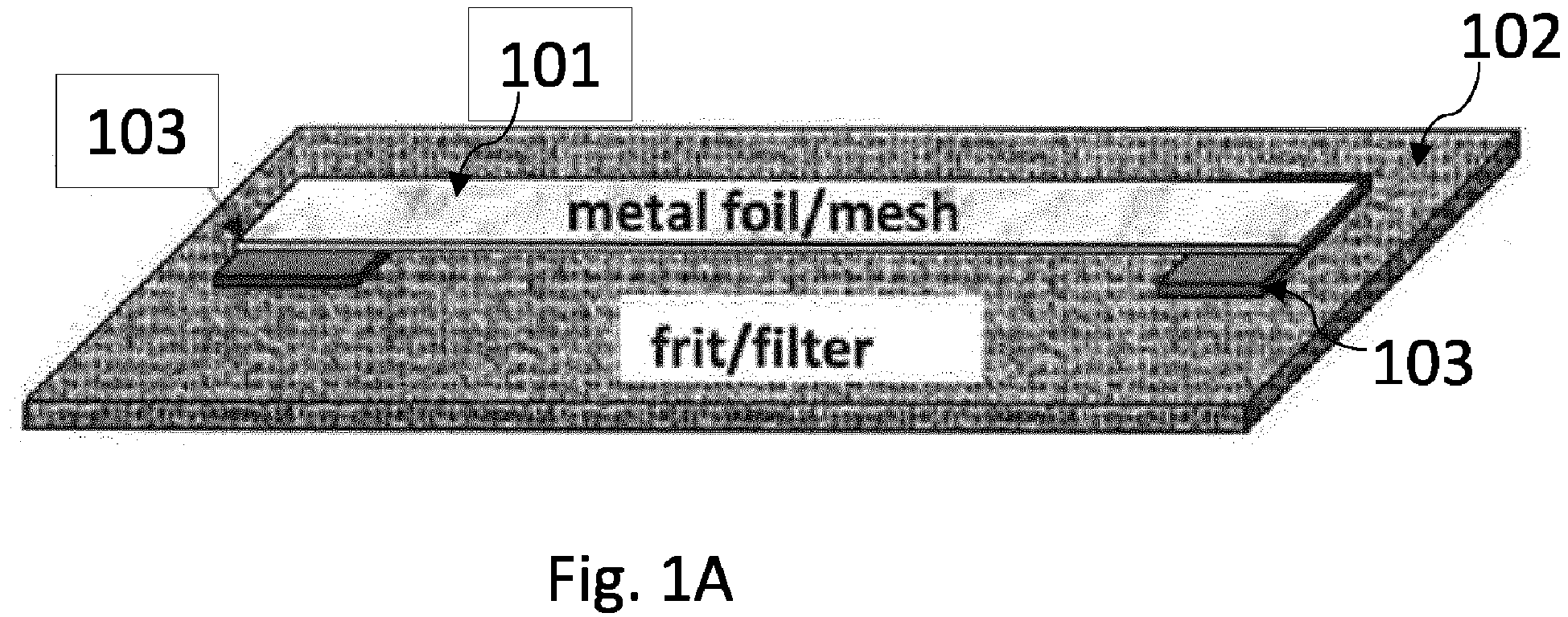
- Figs. 1A-1D show a schematic of a method for battery tab attachment to a self-standing electrode according to some aspects of the present disclosure.
- the battery tab attachment structure 101 may be spaced above the first porous surface using any suitable means as may be known to those of ordinary skill in the art, including, but not limited to, positioning one or more spacers 103 onto the first porous surface 102 and positioning the battery tab attachment structure 101 onto the one or more spacers 103.
- the one or more spacers 103 are positioned on the porous surface 102, and the battery tab attachment structure 101 is positioned on the one or more spacers 103, so as to leave a vertical gap h between the battery tab attachment structure 101 and the first porous surface 102 for a portion of the length of the battery tab attachment structure 101, so that the aerosolized electrode active material and the carbon nanotubes may co-deposit above and below the battery tab attachment structure 101, i.e., both above the battery tab attachment structure 101 and above the first porous surface 102 but below the battery tab attachment structure 101.
- the vertical gap h may be of any size relative to the battery tab attachment structure 101 thickness.
- the battery tab attachment structure 101 may be of any thickness, such as about 5 ⁇ m to about 2000 ⁇ m, such as about 10 ⁇ m to about 290 ⁇ m, such as about 100 ⁇ m or about 15 ⁇ m, or any other integer or subrange in between.
- Tab attachment structure width and thickness depend on the electrode size and the weight of the active material in it, and, therefore, the current the tab needs to carry. Based on the conductance of tab attachment structure and tab materials, and the current it needs to carry, the minimal tab attachment structure geometry (especially its cross-section area) can be calculated.
- the battery tab attachment structure may be embedded within the composite at any depth. In some aspects, it is embedded at a depth that is halfway through the overall thickness of the self-standing electrode.
- two spacers 103 may be used. Suitable spacer materials include, but are not limited to paper, cellulose, and polymeric materials.
- the one or more spacers 103 may be of any dimensions and shape relative to the porous surface 102 and/or the battery tab attachment structure 101, but preferably the one or more spacers 103 are wider than the battery tab attachment structure, so as to facilitate removal of the self-standing electrode material after the co-depositing.
- the co-depositing may occur over any duration of time.
- the overall thickness of the self-standing electrode may be determined by one or more factors including but not limited to the duration of time of co-depositing, the flow rate of the aerosolized or fluidized electrode active material and/or the single walled carbon nanotubes, the concentrations of the aerosolized or fluidized electrode active material and/or the single walled carbon nanotubes, the thickness of the battery tab attachment structure, and the size of the vertical gap h.
- about 20 minutes of co-depositing may result in a self-standing electrode with an overall thickness of about 30 ⁇ m.
- about 2 hours of co-depositing may result in a self-standing electrode with an overall thickness of about 100 ⁇ m.
- Those of ordinary skill in the art will be able to vary those factors to obtain self-standing electrodes of desired thickness and/or other properties, such as electric chare or energy charge.
- flow rate and/or concentrations of the aerosolized or fluidized electrode active material and/or the single walled carbon nanotubes may be varied using the methods and apparatuses disclosed in U.S. Patent Application No. 15/665,171 , entitled “Self Standing Electrodes and Methods for Making Thereof," filed July 31, 2017 with attorney docket no. 037110.00687, and U.S. Patent Application No.
- the overall thickness of the self-standing electrode may be modified by pressing, which may reduce the overall thickness by as much as half.
- a self-standing electrode with an overall thickness of 100 ⁇ m may be pressed to a thickness of 50 ⁇ m. Pressing may also modify the density of the composite and/or the battery tab attachment structure.
- Suitable methods and apparatuses for pressing electrodes are known in the art and include but are not limited to those disclosed in U.S. Patent Application No. 15/665,171 , entitled “Self Standing Electrodes and Methods for Making Thereof," filed July 31, 2017 with attorney docket no. 037110.00687, and U.S. Patent Application No.
- a narrow and thin conductive strip/wire/grid is embedded into a self-standing electrode during its formation ( Figs. 1A-1D ).
- metal piece 101 which may be thin aluminum or copper strips, wire, or mesh, was spaced a distance h above a frit or mesh 102 (using spacers 103) that serves as a substrate/filter for simultaneous deposition of a mixture of an electrode active material powder and a carbon nanotube additive ( Figs. 1A-B ).
- the carbon nanotube additive may comprise single-walled carbon nanotubes, multi-walled carbon nanotubes, and mixtures thereof.
- the dimensions of the strip or wire 101 can be very small compared to the electrode size.
- the electrode active material and the carbon nanotube additive grows around, below, above, and/or on the metal strips, wire, or mesh 101, encapsulating these metal structure(s) 101 inside the mixture of the electrode active material and the carbon nanotube additive ( Figs. 1C-D ).
- Frit 102 also serves as a filter to filter gases in direction 105.
- the electrode film 106 with the metal structures 101 inside it is pressed to the desired density using a roller mill or another method, thus resulting in a self-standing composite electrode with the metal structure embedded in it.
- the metal structure 101 can protrude outside of the electrode 106, providing an electric tab attachment spot.
- the embedded conductive structure can be a metal mesh or a conductive permeable membrane (e.g., made of conductive polymers), which itself serves as a substrate/filter for electrode formation/deposition. This can be used either for electrode growth from gas phase (e.g., aerosol), or for deposition from a liquid phase (e.g., from a mixture or suspension).
- gas phase e.g., aerosol
- liquid phase e.g., from a mixture or suspension
- the conductive substrate/filter is embedded into the material by a pressing procedure, as described above.
- Fig. 2a shows an example of an aluminum mesh 101 on the frit.
- Fig. 2b shows the example of Fig. 2a upon deposition of the mixture of the carbon nanotube (CNT) and the electrode active material.
- Fig. 2c shows an example of an aluminum mesh 101 embedded in a self-standing electrode.
- the present disclosure is directed to methods and embedding battery tab attachment structures within composites of electrode active materials and carbon nanotubes, which lack binder and lack collector foils, and the resulting self-standing electrodes. Such methods and the resulting self-standing electrodes may facilitate the use of such composites in battery and power applications.
Landscapes
- Chemical & Material Sciences (AREA)
- Chemical Kinetics & Catalysis (AREA)
- Electrochemistry (AREA)
- General Chemical & Material Sciences (AREA)
- Engineering & Computer Science (AREA)
- Manufacturing & Machinery (AREA)
- Materials Engineering (AREA)
- Inorganic Chemistry (AREA)
- Dispersion Chemistry (AREA)
- Battery Electrode And Active Subsutance (AREA)
- Cell Electrode Carriers And Collectors (AREA)
Abstract


Description
- This application claims priority to
U.S. Patent Application No. 62/559,254 - A Li-ion battery consists of two electrodes (anode and cathode), a membrane separating anode from cathode, and electrolyte. Electrodes consist of an active material, a binder, a carbon-based additive and current collectors. Aluminum/Copper foils are typical current collectors for Li-ion batteries. Usually, the active material is printed on the surface of the current collectors using a slurry consisting of the active material, the additive, a binder, and a proper solvent. After preparation of the electrode, an electrically conductive tab is attached to the current collector to get the current out of the battery. Commonly, the tab is a strip of aluminum/copper foil, which is welded to the current collector foil of the electrodes.
- In the case of self-standing electrodes, comprising only the active material powder and carbon nanotube matrix, and in which no collector foil is present, a method is needed for transporting the current from the electrodes. In other words, it is necessary to solve the problem of tab attachment to the electrode, which does not have any current collector foils.
- The following presents a simplified summary of one or more aspects of the present disclosure in order to provide a basic understanding of such aspects. This summary is not an extensive overview of all contemplated aspects and is intended to neither identify key or critical elements of all aspects nor delineate the scope of any or all aspects. Its purpose is to present some concepts of one or more aspects in a simplified form as a prelude to the more detailed description that is presented later.
- In some embodiments, the present disclosure is directed to a self-standing electrode comprising: a composite of an electrode active material, and carbon nanotubes; and a battery tab attachment structure embedded in the composite, wherein the electrode has an overall length, an overall width, and an overall thickness, and the battery tab attachment structure has a width that is about 1% to about 100% of the overall width of the electrode.
- In some embodiments, the present disclosure is directed to a method of making a binderless, collectorless self-standing electrode, the method comprising: aerosolizing or fluidizing an electrode active material to produce an aerosolized or fluidized electrode active material; and co-depositing the aerosolized or fluidized electrode active material and carbon nanotubes onto a first porous surface, and a battery tab attachment structure spaced above the first porous surface to form a self-standing electrode material that is a composite of the electrode active material in a three-dimensional network of carbon nanotubes with the battery tab attachment structure embedded within the self-standing electrode material, wherein the electrode has an overall length, an overall width, and an overall thickness, and the battery tab attachment structure has a width that is about 1% to about 100% of the overall width of the electrode.
- These and other aspects of the invention will become more fully understood upon a review of the detailed description, which follows.
-
-
Figs. 1A-1D show a schematic of a method for battery tab attachment to a self-standing electrode according to some aspects of the present disclosure. -
Figs. 2A-2C show examples of images of tab attachment according to the aspects depicted inFigs. 1A-1D . - The detailed description set forth below in connection with the appended drawings is intended as a description of various configurations and is not intended to represent the only configurations in which the concepts described herein may be practiced. The detailed description includes specific details for the purpose of providing a thorough understanding of various concepts. However, it will be apparent to those skilled in the art that these concepts may be practiced without these specific details.
- The present disclosure provides self-standing electrodes comprising a composite of carbon nanotubes and electrode active materials, with a battery tab attachment structure embedded in the composite, and methods of making the same.
- In some embodiments, the present disclosure is directed to a self-standing electrode comprising: a composite of an electrode active material, and carbon nanotubes; and a battery tab attachment structure embedded in the composite, wherein the electrode has an overall length, an overall width, and an overall thickness, and the battery tab attachment structure has a width that is about 1% to about 100% of the overall width of the electrode. In some aspects, the battery tab attachment structure width is about 10% to about 75% of the overall width of the electrode.
- As used herein, "electrode active material" refers to the conductive material in an electrode. The term "electrode" refers to an electrical conductor where ions and electrons are exchanged with an electrolyte and an outer circuit. "Positive electrode" and "cathode" are used synonymously in the present description and refer to the electrode having the higher electrode potential in an electrochemical cell (i.e., higher than the negative electrode). "Negative electrode" and "anode" are used synonymously in the present description and refer to the electrode having the lower electrode potential in an electrochemical cell (i.e., lower than the positive electrode). Cathodic reduction refers to gain of electron(s) of a chemical species, and anodic oxidation refers to the loss of electron(s) of a chemical species.
- In a non-limiting example, the electrode active material may be any solid, metal oxide powder that is capable of being aerosolized. In an illustrative example, the metal oxide is a material for use in the cathode of the battery. Non-limiting examples of metal oxides include oxides of Ni, Mn, Co, Al, Mg, Ti, and any mixture thereof. The metal oxide may be lithiated. In an illustrative example, the metal oxide is lithium nickel manganese cobalt oxide (LiNiMnCoO2). The metal oxide powders can have a particle size defined within a range between about 1 nanometer and about 100 microns. In a non-limiting example, the metal oxide particles have an average particle size of about 1 nm to about 10 nm. In some aspects, the electrode active material is selected from graphite, hard carbon, silicon, silicon oxides, lithium metal oxides, lithium iron phosphate, and lithium metal.
- Metals in lithium metal oxides according to the present disclosure may include but are not limited to one or more alkali metals, alkaline earth metals, transition metals, aluminum, or post-transition metals, and hydrates thereof.
- "Alkali metals" are metals in Group I of the periodic table of the elements, such as lithium, sodium, potassium, rubidium, cesium, or francium.
- "Alkaline earth metals" are metals in Group II of the periodic table of the elements, such as beryllium, magnesium, calcium, strontium, barium, or radium.
- "Transition metals" are metals in the d-block of the periodic table of the elements, including the lanthanide and actinide series. Transition metals include, but are not limited to, scandium, titanium, vanadium, chromium, manganese, iron, cobalt, nickel, copper, zinc, yttrium, zirconium, niobium, molybdenum, technetium, ruthenium, rhodium, palladium, silver, cadmium, lanthanum, cerium, praseodymium, neodymium, promethium, samarium, europium, gadolinium, terbium, dysprosium, holmium, erbium, thulium, ytterbium, lutetium, hafnium, tantalum, tungsten, rhenium, osmium, iridium, platinum, gold, mercury, actinium, thorium, protactinium, uranium, neptunium, plutonium, americium, curium, berkelium, californium, einsteinium, fermium, mendelevium, nobelium, and lawrencium.
- "Post-transition metals" include, but are not limited to, gallium, indium, tin, thallium, lead, bismuth, or polonium.
- As used herein, suitable composites of "an electrode active material and single-walled carbon nanotubes" include, but are not limited to, self-standing electrodes such as those disclosed in
U.S. Patent Application No. 15/665,171 U.S. Patent Application No. 15/665,142 - In some aspects, the battery tab attachment structure comprises a metal. In some aspects, the metal is copper, aluminum, nickel, or stainless steel. In a non-limiting example, the stainless steel may be any stainless steel known in the art, including, but not limited to, SS304 and SS316. In some aspects, the battery tab attachment structure comprises a conductive carbon structure. The conductive carbon structure may comprise carbon nanotubes, graphene, (such as two- and three-dimensional graphene forms, such as graphene foams), carbon fibers, graphite, or any other conductive allotropic form of carbon, or a combination thereof, or a composite thereof. The carbon nanotubes may be single-, few-, or multi-walled carbon nanotubes, or a combination thereof, with single-walled carbon nanotubes being preferred. When carbon nanotubes and/or carbon fibers are used, the carbon nanotubes and/or carbon fibers may be in the form of nanotube yarn, nanotube threads, nanotube cloth, nanotube wires, nanotube paper (i.e., buckypaper), nanotube mats, nanotube sheets, or nanotube felt. The battery tab attachment structure may be in any solid physical form, including but not limited to, foil, strips, wire, grid, ropes, mesh foil, perforated foil, cloth, gauze, or mesh. The battery tab attachment structure may be embedded in the composite by a process of co-depositing aerosolized or fluidized electrode active material and single-walled carbon nanotubes onto a first porous surface with the battery tab attachment structure spaced above it. The aerosolized or fluidized electrode active material and single-walled carbon nanotubes may be present in a mixture together or may not contact each other prior to the co-depositing or co-deposition. Suitable co-depositing methods and apparatuses may be known in the art and include, but are not limited to, those described in
U.S. Patent Application No. 15/665,171 U.S. Patent Application No. 15/665,142 - The self-standing electrode of the present disclosure may be characterized by an overall length, an overall width, and an overall thickness, including both the composite and the battery tab attachment structure embedded therein. In some aspects, the overall thickness of the electrode is from about 10 µm to about 5000 µm, such as from about 20 µm to about 300 µm, or any integer or subrange in between. In some aspects, the electrode has an overall thickness of about 20 µm to about 100 µm. In some aspects, the electrode has an overall thickness of about 20 µm to about 75 µm. the electrode has an overall thickness of about 20 µm to about 50 µm. the electrode has an overall thickness of about 20 µm to about 40 µm.
- According to the present disclosure, the battery tab attachment structure has a width that is about 10% to about 75% of the overall width of the electrode. In some aspects, the battery tab attachment structure has a width that is about 10% to about 50% of the overall width of the electrode. In some aspects, the battery tab attachment structure has a width that is about 10% to about 30% of the overall width of the electrode. In some aspects, the battery tab attachment structure has a width that is about 3% to about 10% of the overall width of the electrode.
- In other embodiments, the present disclosure is directed to a method of making a binderless, collectorless self-standing electrode, the method comprising: aerosolizing or fluidizing an electrode active material to produce an aerosolized or fluidized electrode active material; and co-depositing the aerosolized or fluidized electrode active material and carbon nanotubes onto a first porous surface, and a battery tab attachment structure spaced above the first porous surface to form a self-standing electrode material that is a composite of the electrode active material in a three-dimensional network of carbon nanotubes with the battery tab attachment structure embedded within the self-standing electrode material, wherein the electrode has an overall length, an overall width, and an overall thickness, and the battery tab attachment structure has a width that is about 1% to about 100% of the overall width of the electrode. All aspects described with respect to the self-standing electrode apply with equal force to the method of making the binderless, collectorless self-standing electrode, and vice versa. The carbon nanotubes may be single-walled, few-walled, or multi-walled, or a combination thereof.
- In some aspects, the co-depositing the aerosolized or fluidized electrode active material and carbon nanotubes onto the first porous surface and the battery tab attachment structure spaced above the first porous surface comprises simultaneously contacting with the first porous surface and the battery tab attachment structure spaced above the first porous surface the aerosolized or fluidized electrode active material and the carbon nanotubes, wherein the aerosolized or fluidized electrode active material and the carbon nanotubes were not previously in contact with one another. Suitable methods and apparatuses for production of carbon nanotubes and aerosolization or fluidization of electrode active materials for simultaneous deposition, wherein the aerosolized or fluidized electrode active material and the single-walled carbon nanotubes do not contact each other prior to their simultaneous deposition, include those known to persons of ordinary skill in the art, including, but not limited to, those described in
U.S. Patent Application No. 15/665,142 - In some aspects, the co-depositing the aerosolized or fluidized active material and carbon nanotubes onto the first porous surface and the battery tab attachment structure spaced above the first porous surface comprises contacting the aerosolized electrode active material powder with the carbon nanotubes in a carrier gas to form a mixture of the carbon nanotubes and the aerosolized electrode active material powder; collecting the mixture on the first porous surface and the battery tab attachment structure spaced above the first porous surface; and removing the carrier gas. Suitable methods and apparatuses for contacting the aerosolized electrode active material powder with the carbon nanotubes in a carrier gas to form a mixture of the single-walled carbon nanotubes and the aerosolized electrode active material powder, suitable porous surfaces, and suitable methods and apparatuses for removing carrier gases are known to those of ordinary skill in the art and include, but are not limited to, those disclosed in
U.S. Patent Application No. 15/665,171 -
Figs. 1A-1D show a schematic of a method for battery tab attachment to a self-standing electrode according to some aspects of the present disclosure. The batterytab attachment structure 101 may be spaced above the first porous surface using any suitable means as may be known to those of ordinary skill in the art, including, but not limited to, positioning one ormore spacers 103 onto the firstporous surface 102 and positioning the batterytab attachment structure 101 onto the one ormore spacers 103. Preferably, the one ormore spacers 103 are positioned on theporous surface 102, and the batterytab attachment structure 101 is positioned on the one ormore spacers 103, so as to leave a vertical gap h between the batterytab attachment structure 101 and the firstporous surface 102 for a portion of the length of the batterytab attachment structure 101, so that the aerosolized electrode active material and the carbon nanotubes may co-deposit above and below the batterytab attachment structure 101, i.e., both above the batterytab attachment structure 101 and above the firstporous surface 102 but below the batterytab attachment structure 101. The vertical gap h may be of any size relative to the batterytab attachment structure 101 thickness. The batterytab attachment structure 101 may be of any thickness, such as about 5 µm to about 2000 µm, such as about 10 µm to about 290 µm, such as about 100 µm or about 15 µm, or any other integer or subrange in between. Tab attachment structure width and thickness depend on the electrode size and the weight of the active material in it, and, therefore, the current the tab needs to carry. Based on the conductance of tab attachment structure and tab materials, and the current it needs to carry, the minimal tab attachment structure geometry (especially its cross-section area) can be calculated. The battery tab attachment structure may be embedded within the composite at any depth. In some aspects, it is embedded at a depth that is halfway through the overall thickness of the self-standing electrode. - In some aspects, two
spacers 103 may be used. Suitable spacer materials include, but are not limited to paper, cellulose, and polymeric materials. The one ormore spacers 103 may be of any dimensions and shape relative to theporous surface 102 and/or the batterytab attachment structure 101, but preferably the one ormore spacers 103 are wider than the battery tab attachment structure, so as to facilitate removal of the self-standing electrode material after the co-depositing. - The co-depositing may occur over any duration of time. Without wishing to be bound by any particular theory, the overall thickness of the self-standing electrode may be determined by one or more factors including but not limited to the duration of time of co-depositing, the flow rate of the aerosolized or fluidized electrode active material and/or the single walled carbon nanotubes, the concentrations of the aerosolized or fluidized electrode active material and/or the single walled carbon nanotubes, the thickness of the battery tab attachment structure, and the size of the vertical gap h. In some aspects, about 20 minutes of co-depositing may result in a self-standing electrode with an overall thickness of about 30 µm. In some aspects, about 2 hours of co-depositing may result in a self-standing electrode with an overall thickness of about 100 µm. Those of ordinary skill in the art will be able to vary those factors to obtain self-standing electrodes of desired thickness and/or other properties, such as electric chare or energy charge. For example, flow rate and/or concentrations of the aerosolized or fluidized electrode active material and/or the single walled carbon nanotubes may be varied using the methods and apparatuses disclosed in
U.S. Patent Application No. 15/665,171 U.S. Patent Application No. 15/665,142 - In addition, the overall thickness of the self-standing electrode may be modified by pressing, which may reduce the overall thickness by as much as half. For example, a self-standing electrode with an overall thickness of 100 µm may be pressed to a thickness of 50 µm. Pressing may also modify the density of the composite and/or the battery tab attachment structure. Suitable methods and apparatuses for pressing electrodes are known in the art and include but are not limited to those disclosed in
U.S. Patent Application No. 15/665,171 U.S. Patent Application No. 15/665,142 - A narrow and thin conductive strip/wire/grid is embedded into a self-standing electrode during its formation (
Figs. 1A-1D ). For this purpose,metal piece 101, which may be thin aluminum or copper strips, wire, or mesh, was spaced a distance h above a frit or mesh 102 (using spacers 103) that serves as a substrate/filter for simultaneous deposition of a mixture of an electrode active material powder and a carbon nanotube additive (Figs. 1A-B ). In a non-limiting example, the carbon nanotube additive may comprise single-walled carbon nanotubes, multi-walled carbon nanotubes, and mixtures thereof. The dimensions of the strip orwire 101 can be very small compared to the electrode size. During the deposition of themixture 104 to form an electrode film, the electrode active material and the carbon nanotube additive grows around, below, above, and/or on the metal strips, wire, ormesh 101, encapsulating these metal structure(s) 101 inside the mixture of the electrode active material and the carbon nanotube additive (Figs. 1C-D ). Frit 102 also serves as a filter to filter gases indirection 105. Then, theelectrode film 106 with themetal structures 101 inside it is pressed to the desired density using a roller mill or another method, thus resulting in a self-standing composite electrode with the metal structure embedded in it. The metal structure 101 (foil, strip, wire, mesh, grid, etc.) can protrude outside of theelectrode 106, providing an electric tab attachment spot. The tab can be attached by welding or by another method. As a variant of this method, the embedded conductive structure can be a metal mesh or a conductive permeable membrane (e.g., made of conductive polymers), which itself serves as a substrate/filter for electrode formation/deposition. This can be used either for electrode growth from gas phase (e.g., aerosol), or for deposition from a liquid phase (e.g., from a mixture or suspension). Then, the conductive substrate/filter is embedded into the material by a pressing procedure, as described above.Fig. 2a shows an example of analuminum mesh 101 on the frit.Fig. 2b shows the example ofFig. 2a upon deposition of the mixture of the carbon nanotube (CNT) and the electrode active material.Fig. 2c shows an example of analuminum mesh 101 embedded in a self-standing electrode. - This written description uses examples to disclose the invention, including the preferred embodiments, and also to enable any person skilled in the art to practice the invention, including making and using any devices or systems and performing any incorporated methods. The patentable scope of the invention is defined by the claims, and may include other examples that occur to those skilled in the art. Such other examples are intended to be within the scope of the claims if they have structural elements that do not differ from the literal language of the claims, or if they include equivalent structural elements with insubstantial differences from the literal language of the claims. Aspects from the various embodiments described, as well as other known equivalents for each such aspect, can be mixed and matched by one of ordinary skill in the art to construct additional embodiments and techniques in accordance with principles of this application.
- The present disclosure is directed to methods and embedding battery tab attachment structures within composites of electrode active materials and carbon nanotubes, which lack binder and lack collector foils, and the resulting self-standing electrodes. Such methods and the resulting self-standing electrodes may facilitate the use of such composites in battery and power applications.
Claims (13)
- A self-standing electrode comprising:a composite ofan electrode active material, andcarbon nanotubes; anda battery tab attachment structure embedded in the composite,wherein the electrode has an overall length, an overall width, and an overall thickness, and the battery tab attachment structure has a width that is about 1% to about 100% of the overall width of the electrode.
- The self-standing electrode of claim 1, wherein the electrode active material is selected from graphite, hard carbon, silicon, silicon oxides, lithium metal oxides, and lithium iron phosphate.
- The self-standing electrode of claim 1 or 2, wherein the battery tab attachment structure comprises a metal, the metal, preferably, being copper, aluminum, nickel or stainless steel
- The electrode of any of claims 1 to 3, wherein the electrode has an overall thickness of about 10 µm to about 5000 µm, preferably of about 20 µm to about 100 µm.
- The electrode of any of claims 1 to 4, wherein the battery tab attachment structure has a width that is about 10% to about 50% of the overall width of the electrode, preferably about 10% to about 30% of the overall width of the electrode, more preferably about 3% to about 10% of the overall width of the electrode.
- The self-standing electrode of any of claims 1 to 5, wherein the battery tab attachment structure comprises a conductive carbon structure.
- The self-standing electrode of claim 6, wherein the conductive carbon structure comprises carbon nanotubes, graphene, carbon fibers, graphite or any other conductive allotropic form of carbon, or a combination thereof, or a composite of thereof, wherein, preferably, the carbon nanotubes and/or carbon fibers are in the form of nanotube yarn, nanotube threads, nanotube cloth, nanotube wires, nanotube paper, nanotube mats, nanotube sheets, or nanotube felt.
- A method of making a binderless, collectorless self-standing electrode, the method comprising:aerosolizing or fluidizing an electrode active material to produce an aerosolized or fluidized electrode active material; andco-depositing the aerosolized or fluidized electrode active material and carbon nanotubes onto a first porous surface, and a battery tab attachment structure spaced above the first porous surface to form a self-standing electrode material that is a composite of the electrode active material in a three-dimensional network of carbon nanotubes with the battery tab attachment structure embedded within the self-standing electrode material,wherein the electrode has an overall length, an overall width, and an overall thickness, and the battery tab attachment structure has a width that is about 1% to about 100% of the overall width of the electrode.
- The method of claim 8, wherein the co-depositing the aerosolized or fluidized active material and carbon nanotubes onto the first porous surface and the battery tab attachment structure spaced above the first porous surface comprises
contacting the aerosolized electrode active material powder with the carbon nanotubes in a carrier gas to form a mixture of the carbon nanotubes and the aerosolized electrode active material powder;
collecting the mixture on the first porous surface and the battery tab attachment structure spaced above the first porous surface; and
removing the carrier gas. - The method of claim 8 or 9, wherein the electrode active material is selected from graphite, hard carbon, silicon, silicon oxides, lithium metal oxides, lithium iron phosphate and lithium metal.
- The method of any of claims 8 to 10, wherein the battery tab attachment structure comprises a metal, the metal, preferably, being copper, aluminum, nickel, or stainless steel.
- The method of any of claims 8 to 11, wherein the electrode has an overall thickness of about 10 µm to about 5000 µm, preferably of about 20 µm to about 100 µm.
- The method of any of claims 6 to 10, wherein the battery tab attachment structure has a width that is about 10% to about 50% of the overall width of the electrode, preferably about 10% to about 30% of the overall width of the electrode, more preferably about 10% to about 20% of the overall width of the electrode.
Applications Claiming Priority (2)
| Application Number | Priority Date | Filing Date | Title |
|---|---|---|---|
| US201762559254P | 2017-09-15 | 2017-09-15 | |
| US16/123,872 US11121358B2 (en) | 2017-09-15 | 2018-09-06 | Method for embedding a battery tab attachment in a self-standing electrode without current collector or binder |
Publications (2)
| Publication Number | Publication Date |
|---|---|
| EP3457466A1 true EP3457466A1 (en) | 2019-03-20 |
| EP3457466B1 EP3457466B1 (en) | 2021-10-06 |
Family
ID=63592575
Family Applications (1)
| Application Number | Title | Priority Date | Filing Date |
|---|---|---|---|
| EP18194469.5A Active EP3457466B1 (en) | 2017-09-15 | 2018-09-14 | Method of embedding a battery tab attachment in a self-standing electrode without current collector or binder and self-standing electrode |
Country Status (5)
| Country | Link |
|---|---|
| US (2) | US11121358B2 (en) |
| EP (1) | EP3457466B1 (en) |
| JP (1) | JP7055081B2 (en) |
| KR (2) | KR102399403B1 (en) |
| CN (1) | CN109509866B (en) |
Cited By (1)
| Publication number | Priority date | Publication date | Assignee | Title |
|---|---|---|---|---|
| WO2024260495A1 (en) * | 2023-06-21 | 2024-12-26 | Bayerische Motoren Werke Aktiengesellschaft | Method for producing an electrode, electrode, and stored energy source comprising the electrode |
Families Citing this family (9)
| Publication number | Priority date | Publication date | Assignee | Title |
|---|---|---|---|---|
| US12142771B2 (en) | 2019-01-30 | 2024-11-12 | Honda Motor Co., Ltd. | Flexible battery as an integration platform for wearable sensors and processing/transmitting devices |
| US12381275B2 (en) | 2019-01-30 | 2025-08-05 | Honda Motor Co., Ltd. | Stretchable and flexible lithium ion battery |
| SG11202110262RA (en) * | 2019-03-22 | 2021-10-28 | Aspen Aerogels Inc | Carbon aerogel-based cathodes for lithium-air batteries |
| US11539042B2 (en) * | 2019-07-19 | 2022-12-27 | Honda Motor Co., Ltd. | Flexible packaging with embedded electrode and method of making |
| CN114175331A (en) * | 2019-07-22 | 2022-03-11 | 本田技研工业株式会社 | Stretchable flexible lithium ion battery |
| JP7674111B2 (en) * | 2021-02-19 | 2025-05-09 | パナソニックエナジー株式会社 | Battery and method for manufacturing battery |
| US12346765B2 (en) | 2021-09-20 | 2025-07-01 | Honda Motor Co., Ltd | Energy storage device with wireless operando monitoring |
| US12347864B2 (en) | 2022-08-05 | 2025-07-01 | Honda Motor Co., Ltd. | Additives for self-standing electrodes |
| CN115036515A (en) * | 2022-08-12 | 2022-09-09 | 清华大学 | Carbon nano material composite current collector, preparation method thereof, electrode and battery |
Citations (3)
| Publication number | Priority date | Publication date | Assignee | Title |
|---|---|---|---|---|
| US3772084A (en) * | 1972-02-11 | 1973-11-13 | Scholle Corp | Method of making negative battery plates |
| US20110311874A1 (en) * | 2010-04-30 | 2011-12-22 | University Of Southern California | Silicon-Carbon Nanostructured Electrodes |
| US20140013588A1 (en) * | 2012-07-13 | 2014-01-16 | Jia-Ping Wang | Method for making thin film lithium ion battery |
Family Cites Families (266)
| Publication number | Priority date | Publication date | Assignee | Title |
|---|---|---|---|---|
| US3513034A (en) | 1956-04-06 | 1970-05-19 | Us Army | Terminal for thermal cells |
| JPH06267515A (en) | 1993-03-15 | 1994-09-22 | Ricoh Co Ltd | Sheet-like secondary battery and electronic element using it |
| JP4083260B2 (en) | 1997-07-09 | 2008-04-30 | 松下電器産業株式会社 | Method for producing electrode plate of non-aqueous electrolyte secondary battery |
| JPH1187875A (en) | 1997-09-12 | 1999-03-30 | Seiko Epson Corp | Manufacturing method of sheet-like electronic equipment |
| US5985175A (en) | 1998-08-19 | 1999-11-16 | Osram Sylvania Inc. | Boron oxide coated phosphor and method of making same |
| AU782000B2 (en) | 1999-07-02 | 2005-06-23 | President And Fellows Of Harvard College | Nanoscopic wire-based devices, arrays, and methods of their manufacture |
| US6919064B2 (en) | 2000-06-02 | 2005-07-19 | The Board Of Regents Of The University Of Oklahoma | Process and apparatus for producing single-walled carbon nanotubes |
| US20090286675A1 (en) | 2001-05-25 | 2009-11-19 | Tsinghua University | Continuous mass production of carbon nanotubes in a nano-agglomerate fluidized-bed and the reactor |
| FR2826646B1 (en) | 2001-06-28 | 2004-05-21 | Toulouse Inst Nat Polytech | PROCESS FOR THE SELECTIVE MANUFACTURE OF ORDINATED CARBON NANOTUBES IN FLUIDIZED BED |
| US20030099883A1 (en) | 2001-10-10 | 2003-05-29 | Rosibel Ochoa | Lithium-ion battery with electrodes including single wall carbon nanotubes |
| US6623562B2 (en) | 2001-11-07 | 2003-09-23 | Ovonic Battery Company, Inc. | Apparatus for fabricating pasted electrodes |
| JP4336869B2 (en) | 2001-11-27 | 2009-09-30 | 日本電気株式会社 | Vacuum film forming apparatus, vacuum film forming method, and battery electrode manufacturing method |
| US6673489B2 (en) | 2001-12-28 | 2004-01-06 | Quallion Llc | Electric battery assembly and method of manufacture |
| CA2374848A1 (en) | 2002-03-06 | 2003-09-06 | Centre National De La Recherche Scientifique | A process for the mass production of multiwalled carbon nanotubes |
| JP2005521453A (en) | 2002-03-29 | 2005-07-21 | コーニンクレッカ フィリップス エレクトロニクス エヌ ヴィ | Detection and alarm system |
| KR100759547B1 (en) | 2002-07-29 | 2007-09-18 | 삼성에스디아이 주식회사 | Carbon Nanotubes for Fuel Cell, Manufacturing Method and Fuel Cell Employing the Same |
| DE10253399A1 (en) | 2002-11-15 | 2004-05-27 | Eramet & Comilog Chemicals S.A. | Metal-coated carbon black, useful as ferromagnetic material or in e.g. medical valve applications, involve use of nickel, iron, cobalt, yttrium, copper or iridium as the metal |
| JP4062171B2 (en) | 2003-05-28 | 2008-03-19 | ソニー株式会社 | Manufacturing method of laminated structure |
| GB0312871D0 (en) | 2003-06-05 | 2003-07-09 | Rolls Royce Plc | A stator core |
| US20050063891A1 (en) | 2003-09-02 | 2005-03-24 | Cambridge University Technical Services Limited | Method of producing carbon nanoparticles |
| US7682590B2 (en) | 2003-11-27 | 2010-03-23 | National Institute Of Advanced Industrial Science And Technology | Carbon nanotube dispersed polar organic solvent and method for producing the same |
| US20050209392A1 (en) | 2003-12-17 | 2005-09-22 | Jiazhong Luo | Polymer binders for flexible and transparent conductive coatings containing carbon nanotubes |
| JP2005290292A (en) | 2004-04-02 | 2005-10-20 | National Institute Of Advanced Industrial & Technology | Carbon nanotube-dispersed polyimide saturable absorber |
| EP1716610B1 (en) | 2004-02-06 | 2011-08-24 | A 123 Systems, Inc. | Lithium secondary cell with high charge and discharge rate capability |
| FI121334B (en) | 2004-03-09 | 2010-10-15 | Canatu Oy | Method and apparatus for making carbon nanotubes |
| JP4410010B2 (en) | 2004-03-26 | 2010-02-03 | 東邦瓦斯株式会社 | Method for producing nanocarbon material |
| JP4625296B2 (en) | 2004-03-31 | 2011-02-02 | 日立マクセル株式会社 | Non-aqueous secondary battery and electronic device using the same |
| DE102004036170B4 (en) | 2004-07-26 | 2007-10-11 | Schott Ag | Vacuum coating system and method for vacuum coating and their use |
| US20060078489A1 (en) | 2004-09-09 | 2006-04-13 | Avetik Harutyunyan | Synthesis of small and narrow diameter distributed carbon single walled nanotubes |
| KR100682862B1 (en) | 2005-01-11 | 2007-02-15 | 삼성에스디아이 주식회사 | Electrochemical Battery Electrode, Manufacturing Method thereof And Electrochemical Battery Using The Same |
| US20060245996A1 (en) | 2005-04-27 | 2006-11-02 | Peking University | Method of synthesizing single walled carbon nanotubes |
| TW200700312A (en) | 2005-06-23 | 2007-01-01 | Univ Nat Chunghsing | Method for dispersing carbon nanotube in water and detection agent thereof |
| WO2008054349A2 (en) | 2005-07-07 | 2008-05-08 | The University Of Maryland | Carbon nanotube structures formed on large free floating substrates |
| JP2007049789A (en) | 2005-08-08 | 2007-02-22 | Nec Corp | Information processing apparatus |
| US8084158B2 (en) | 2005-09-02 | 2011-12-27 | A123 Systems, Inc. | Battery tab location design and method of construction |
| US8703092B2 (en) | 2005-09-15 | 2014-04-22 | University Of Florida Research Foundation, Inc. | Type separation of single-walled carbon nanotubes via two-phase liquid extraction |
| FI120195B (en) | 2005-11-16 | 2009-07-31 | Canatu Oy | Carbon nanotubes functionalized with covalently bonded fullerenes, process and apparatus for producing them, and composites thereof |
| US20120105370A1 (en) | 2005-12-12 | 2012-05-03 | Nupix, LLC | Electroded Sheet for a Multitude of Products |
| FR2895393B1 (en) | 2005-12-23 | 2008-03-07 | Arkema Sa | PROCESS FOR THE SYNTHESIS OF CARBON NANOTUBES |
| DE102006024550A1 (en) | 2006-05-23 | 2007-11-29 | Bayer Materialscience Ag | Temperature stable catalyst for the gas phase oxidation |
| TW200801223A (en) | 2006-06-01 | 2008-01-01 | Ritek Corp | Method of preparing single wall carbon nanotubes |
| US20080233402A1 (en) | 2006-06-08 | 2008-09-25 | Sid Richardson Carbon & Gasoline Co. | Carbon black with attached carbon nanotubes and method of manufacture |
| EP2059474B1 (en) | 2006-08-31 | 2018-10-03 | Nano-C, Inc. | Direct liquid-phase collection and processing of fullerenic materials |
| CN100450922C (en) | 2006-11-10 | 2009-01-14 | 清华大学 | A kind of ultra-long oriented carbon nanotube wire/film and preparation method thereof |
| US8684284B2 (en) | 2006-11-24 | 2014-04-01 | Honda Motor Co., Ltd. | Injector for large amount of aerosol powder for synthesis of carbon nanotubes |
| FR2909989A1 (en) | 2006-12-18 | 2008-06-20 | Arkema France | Catalyst material for production of multi-shell carbon fibrils and nanotubes for use e.g. as reinforcing material, contains multivalent transition metal and a solid organic substrate |
| FR2914634B1 (en) | 2007-04-06 | 2011-08-05 | Arkema France | PROCESS FOR PRODUCING CARBON NANOTUBES FROM RENEWABLE RAW MATERIALS |
| WO2008124167A1 (en) | 2007-04-10 | 2008-10-16 | The Regents Of The University Of California | Charge storage devices containing carbon nanotube films as electrodes and charge collectors |
| JP5152743B2 (en) | 2007-06-06 | 2013-02-27 | 本城金属株式会社 | ELECTRODE FOR LITHIUM SECONDARY BATTERY AND METHOD FOR PRODUCING THE SAME |
| DE102007044031A1 (en) | 2007-09-14 | 2009-03-19 | Bayer Materialscience Ag | Carbon nanotube powder, carbon nanotubes and methods of making same |
| WO2009089018A2 (en) | 2008-01-08 | 2009-07-16 | Sion Power Corporation | Porous electrodes and associated methods |
| US20090117026A1 (en) | 2007-10-01 | 2009-05-07 | Denso Corporation | Method for manufacturing carbon nano-tube |
| JP5473148B2 (en) | 2007-11-14 | 2014-04-16 | チェイル インダストリーズ インコーポレイテッド | Transparent conductive film with improved conductivity and method for producing the same |
| CN201122624Y (en) | 2007-11-30 | 2008-09-24 | 比亚迪股份有限公司 | An electrode lead-out structure and a battery comprising the electrode lead-out structure |
| DE102007062421A1 (en) | 2007-12-20 | 2009-06-25 | Bayer Technology Services Gmbh | Process for the preparation of nitrogen-doped carbon nanotubes |
| US8435676B2 (en) | 2008-01-09 | 2013-05-07 | Nanotek Instruments, Inc. | Mixed nano-filament electrode materials for lithium ion batteries |
| EP2274788A4 (en) | 2008-03-07 | 2012-01-25 | Leyden Energy Inc | Electrochemical cells with tabs |
| US9174847B2 (en) | 2008-05-01 | 2015-11-03 | Honda Motor Co., Ltd. | Synthesis of high quality carbon single-walled nanotubes |
| US20120315539A1 (en) | 2008-05-07 | 2012-12-13 | Nanocomp Technologies, Inc. | Nanostructure composite batteries and methods of making same from nanostructure composite sheets |
| JP5864253B2 (en) | 2008-05-07 | 2016-02-17 | ナノコンプ テクノロジーズ インコーポレイテッド | Method for forming nanostructured composite sheet |
| US20110171398A1 (en) | 2010-01-12 | 2011-07-14 | Oladeji Isaiah O | Apparatus and method for depositing alkali metals |
| US20130189565A1 (en) | 2008-05-07 | 2013-07-25 | Nanocomp Technologies, Inc. | Batteries Having Nanostructured Composite Cathode |
| JP5291707B2 (en) | 2008-05-30 | 2013-09-18 | 三菱重工業株式会社 | Nanocarbon material manufacturing apparatus and method |
| CN102076605A (en) | 2008-06-30 | 2011-05-25 | 昭和电工株式会社 | Process for producing carbon nanomaterial and system for producing carbon nanomaterial |
| US20100000441A1 (en) | 2008-07-01 | 2010-01-07 | Jang Bor Z | Nano graphene platelet-based conductive inks |
| US9099738B2 (en) | 2008-11-03 | 2015-08-04 | Basvah Llc | Lithium secondary batteries with positive electrode compositions and their methods of manufacturing |
| CN102300806B (en) | 2008-12-08 | 2013-11-06 | 赫斯提亚Tec有限公司 | Multicomponent nanoparticle materials and process and apparatus therefor |
| US9406985B2 (en) | 2009-01-13 | 2016-08-02 | Nokia Technologies Oy | High efficiency energy conversion and storage systems using carbon nanostructured materials |
| EP2213369B1 (en) | 2009-01-15 | 2015-07-01 | Carlo Vittorio Mazzocchia | A process for the preparation of a catalyst, a catalyst obtained thereby, and its use in the production of nanotubes |
| US20100221606A1 (en) | 2009-03-02 | 2010-09-02 | Omkaram Nalamasu | Energy storage device with porous electrode |
| JP2010212309A (en) | 2009-03-06 | 2010-09-24 | Nippon Chemicon Corp | Electrode material, and electrode containing the same |
| MY160277A (en) | 2009-04-17 | 2017-02-28 | Seerstone Llc | Method of producing solid carbon by reducing carbon oxides |
| US20100285358A1 (en) | 2009-05-07 | 2010-11-11 | Amprius, Inc. | Electrode Including Nanostructures for Rechargeable Cells |
| JP2010277925A (en) | 2009-05-29 | 2010-12-09 | Sanyo Electric Co Ltd | Paper battery and manufacturing method thereof |
| EP2445041B1 (en) | 2009-06-17 | 2016-04-13 | Sony Corporation | Nonaqueous electrolyte battery, positive electrode for nonaqueous electrolyte battery, negative electrode for nonaqueous electrolyte battery, separator for nonaqueous electrolyte battery, electrolyte for nonaqueous electrolyte battery, and method for producing separator for nonaqueous electrolyte battery |
| CN102471105B (en) | 2009-07-06 | 2015-05-27 | 泽普托公司 | Carbon nanotube composite structures and methods of manufacturing the same |
| EP2284933A1 (en) | 2009-07-22 | 2011-02-16 | Bayer MaterialScience AG | Method for producing extendable electrodes |
| DE102009038464A1 (en) | 2009-08-21 | 2011-02-24 | Bayer Materialscience Ag | Carbon nanotubes agglomerate |
| WO2011030821A1 (en) | 2009-09-10 | 2011-03-17 | 国立大学法人東京大学 | Method for simultaneously producing carbon nanotubes and hydrogen, and device for simultaneously producing carbon nanotubes and hydrogen |
| US20110070495A1 (en) | 2009-09-23 | 2011-03-24 | Alliance For Sustainable Energy, Llc | Method of fabricating electrodes including high-capacity, binder-free anodes for lithium-ion batteries |
| US20110111279A1 (en) | 2009-11-09 | 2011-05-12 | Florida State University Research Foundation Inc. | Binder-free nanocomposite material and method of manufacture |
| KR101193077B1 (en) | 2009-12-04 | 2012-10-22 | 주식회사 루트제이제이 | Active material precursor, active material for secondary lithium battery cathode including nanotube-shaped carbon, manufacturing method for the same |
| US8293204B2 (en) | 2009-12-19 | 2012-10-23 | Abbas Ali Khodadadi | Carbon nanotubes continuous synthesis process using iron floating catalysts and MgO particles for CVD of methane in a fluidized bed reactor |
| US9167736B2 (en) | 2010-01-15 | 2015-10-20 | Applied Nanostructured Solutions, Llc | CNT-infused fiber as a self shielding wire for enhanced power transmission line |
| JP6148012B2 (en) | 2010-01-18 | 2017-06-14 | エネヴェート・コーポレーション | Composite materials for electrochemical storage |
| US8894963B2 (en) | 2010-01-25 | 2014-11-25 | The Texas A&M University System | Dispersion and retrieval of de-bundled nanotubes |
| KR101818640B1 (en) | 2010-03-02 | 2018-01-15 | 어플라이드 나노스트럭처드 솔루션스, 엘엘씨. | Electrical devices containing carbon nanotube-infused fibers and methods for production thereof |
| US20110281156A1 (en) * | 2010-05-17 | 2011-11-17 | Arthur Douglas Boren | Vertically Aligned Carbon Nanotube Augmented lithium Ion Anode for Batteries |
| JP5459398B2 (en) | 2010-05-19 | 2014-04-02 | 日産自動車株式会社 | Bipolar secondary battery |
| US9321694B2 (en) | 2010-09-01 | 2016-04-26 | Dow Global Technologies Llc | Method for applying discriminating layer onto porous ceramic filters via gas-borne prefabricated porous assemblies |
| KR101113976B1 (en) | 2010-10-27 | 2012-03-13 | 한국과학기술연구원 | Composites of self-assembled electrode active material-carbon nanotube, their method of fabrication and secondary battery comprising the same |
| US8568099B2 (en) | 2010-12-17 | 2013-10-29 | Vestas Wind Systems A/S | Apparatus for harvesting energy from a gearbox to power an electrical device and related methods |
| US9001495B2 (en) | 2011-02-23 | 2015-04-07 | Fastcap Systems Corporation | High power and high energy electrodes using carbon nanotubes |
| WO2012151297A1 (en) | 2011-05-02 | 2012-11-08 | Washington University | Spray pyrolysis synthesis of mesoporous positive electrode materials for high energy lithium-ion batteries |
| WO2012153305A2 (en) | 2011-05-12 | 2012-11-15 | Arcaqua (Pty) Ltd | Ozone-based disinfecting device and mixer therefor |
| ITPD20110153A1 (en) | 2011-05-13 | 2012-11-14 | Univ Padova | METHOD OF SYNTHESIS OF CARBON NANOTUBES FUNCTIONALIZED BY CYCLE ADDS IN CONTINUOUS FLOW AND APPARATUS FOR THE SAME |
| CN102790201B (en) | 2011-05-20 | 2016-11-23 | 清华大学 | Lithium ion cell positive and lithium ion battery |
| US9136536B2 (en) | 2011-08-12 | 2015-09-15 | Yazaki Corporation | Method of making cohesive carbon assembly and its applications |
| WO2013038494A1 (en) | 2011-09-13 | 2013-03-21 | 株式会社日立製作所 | Electrode for lithium ion secondary batteries, method for producing same, and lithium ion secondary battery |
| FR2981206B1 (en) | 2011-10-06 | 2013-11-29 | Inst Polytechnique Grenoble | PROCESS FOR THE PREPARATION OF SELF-SUPPORTED FLEXIBLE ELECTRODES |
| EP2764560A4 (en) | 2011-10-07 | 2015-04-29 | Applied Nanostructured Sols | HYBRID BATTERY CAPACITOR AND SUPERCONDENSER WITH ACTIVE BIFUNCTIONAL ELECTROLYTE |
| CN103094526B (en) | 2011-10-28 | 2015-07-29 | 清华大学 | The preparation method of lithium ion cell positive |
| CN103093857B (en) | 2011-10-28 | 2016-04-13 | 清华大学 | Electrode wires and apply the pacemaker of this electrode wires |
| US8758931B2 (en) | 2011-12-02 | 2014-06-24 | Lenovo (Singapore) Pte. Ltd. | Electrochemical cell package |
| US8974960B2 (en) | 2011-12-22 | 2015-03-10 | Board Of Regents, The University Of Texas System | Binder-free sulfur—carbon nanotube composite cathodes for rechargeable lithium—sulfur batteries and methods of making the same |
| CN103187575B (en) | 2011-12-28 | 2015-11-25 | 清华大学 | The preparation method of film lithium ion battery |
| CN103187572B (en) | 2011-12-28 | 2016-01-20 | 清华大学 | Film lithium ion battery |
| JP5514230B2 (en) | 2012-01-04 | 2014-06-04 | 株式会社日立製作所 | Battery module and manufacturing method thereof |
| US8986872B2 (en) | 2012-02-15 | 2015-03-24 | GM Global Technology Operations LLC | Battery design |
| CN102593436A (en) | 2012-02-27 | 2012-07-18 | 清华大学 | Self-supporting flexible carbon nano-tube paper composite electrode material for lithium ion battery |
| US20130224551A1 (en) | 2012-02-29 | 2013-08-29 | Nokia Corporation | Apparatus and Associated Methods |
| FR2988225B1 (en) | 2012-03-13 | 2014-03-28 | Hutchinson | ANODE FOR LITHIUM-ION BATTERY CELL, METHOD FOR MANUFACTURING SAME, AND BATTERY INCORPORATING SAME |
| JP5591280B2 (en) | 2012-04-13 | 2014-09-17 | トヨタ自動車株式会社 | Battery, battery pack |
| US9692056B1 (en) | 2012-04-13 | 2017-06-27 | Amprius, Inc. | Dual current collectors for battery electrodes |
| TWI627130B (en) | 2012-04-18 | 2018-06-21 | 美商艾克頌美孚上游研究公司 | Removing carbon nanotubes from a continuous reactor effluent |
| CN102674316B (en) | 2012-05-09 | 2014-05-07 | 清华大学 | Method for preparing composition of carbon nano tube and graphene by using sheet material |
| DE102012207999A1 (en) | 2012-05-14 | 2013-11-14 | Robert Bosch Gmbh | Sheath foil for a galvanic cell, electrochemical storage, electrochemical storage system, flexible foil for a sheath of a galvanic cell and method for determining a state quantity of an electrochemical storage |
| GB2502305B (en) | 2012-05-22 | 2015-07-29 | Plastic Logic Ltd | Electronic reading devices |
| US20130323583A1 (en) | 2012-05-31 | 2013-12-05 | Dragonfly Energy, LLC | Processes for the manufacture of conductive particle films for lithium ion batteries |
| WO2013187452A1 (en) | 2012-06-13 | 2013-12-19 | 株式会社三五 | Negative electrode for lithium secondary batteries and method for producing same |
| US9528629B2 (en) | 2012-06-27 | 2016-12-27 | Fisher Controls International Llc | Methods and apparatus to use vibration data to determine a condition of a process control device |
| KR20140011683A (en) | 2012-07-18 | 2014-01-29 | 삼성전자주식회사 | Carbon nanotube composite and manufacturing mrthod of the same |
| CN103633292B (en) | 2012-08-22 | 2016-06-15 | 清华大学 | Lithium ion battery negative |
| WO2014070254A1 (en) | 2012-11-01 | 2014-05-08 | Blue Spark Technologies, Inc. | Body temperature logging patch |
| KR101336286B1 (en) | 2012-11-13 | 2013-12-03 | 재단법인대구경북과학기술원 | Manufacturing method for carbon nano fiber complex and carbon nano fiber complex |
| KR101451354B1 (en) * | 2012-12-11 | 2014-10-15 | 인하대학교 산학협력단 | Free-standing carbon nanotube/metal oxide particle composite film and the manufacturing method |
| WO2014094181A1 (en) | 2012-12-20 | 2014-06-26 | Zhongwei Chen | Bi-functional electrode for metal-air batteries and method for producing same |
| DE102012224377A1 (en) | 2012-12-27 | 2014-07-03 | Robert Bosch Gmbh | Method for producing a galvanic element and galvanic element |
| KR20150110513A (en) | 2013-01-17 | 2015-10-02 | 사우디 베이식 인더스트리즈 코포레이션 | Carbon nano-tube production from carbon dioxide |
| JP5725054B2 (en) | 2013-02-08 | 2015-05-27 | トヨタ自動車株式会社 | Composite active material and method for producing the same |
| US10553853B2 (en) | 2013-03-20 | 2020-02-04 | Kansas State University Research Foundation | Flexible composite electrode high-rate performance lithium-ion batteries |
| DE102013204872A1 (en) | 2013-03-20 | 2014-09-25 | Robert Bosch Gmbh | Electrode and method of making the same |
| CN103219467B (en) | 2013-03-27 | 2015-11-11 | 北京大学 | Flexible polymer solar battery of corrugated structures and preparation method thereof |
| CN103280846B (en) | 2013-03-27 | 2016-08-03 | 上海空间电源研究所 | A kind of flexible photovoltaic integration power-supply system |
| JP6098878B2 (en) | 2013-04-17 | 2017-03-22 | トヨタ自動車株式会社 | Non-aqueous electrolyte secondary battery |
| KR102111020B1 (en) | 2013-05-02 | 2020-05-15 | 삼성디스플레이 주식회사 | Deposition apparatus |
| US20140370347A1 (en) | 2013-06-14 | 2014-12-18 | Samsung Sdi Co., Ltd. | Flexible battery |
| FR3007582B1 (en) | 2013-06-24 | 2015-06-26 | Inst Polytechnique Grenoble | METHOD OF PRINTING OR DEPOSITING BY ATOMIZATION FOR PREPARING A SUPPORTED FLEXIBLE ELECTRODE AND MANUFACTURING A LITHIUM-ION BATTERY |
| KR20160026978A (en) | 2013-07-03 | 2016-03-09 | 캘리포니아 인스티튜트 오브 테크놀로지 | Carbon nanotubes-graphene hybrid structures for separator free silicon-sulfur batteries |
| WO2015004673A1 (en) | 2013-07-11 | 2015-01-15 | Newpace Ltd. | Battery and electronics integration in an implantable medical device |
| WO2015016465A1 (en) | 2013-07-31 | 2015-02-05 | 주식회사 엘지화학 | Curved electrode stack and battery pack comprising same |
| US8940446B1 (en) | 2013-08-06 | 2015-01-27 | Quantumscape Corporation | Solid state lithium-air based battery cell |
| EP2835177A1 (en) | 2013-08-06 | 2015-02-11 | Bayer Technology Services GmbH | Method for preparing Co-Mn on carbon catalysts and their use in carbon nanotube synthesis |
| KR102189784B1 (en) | 2013-08-30 | 2020-12-11 | 삼성전자주식회사 | Flexible electronic device |
| US20150087858A1 (en) | 2013-09-25 | 2015-03-26 | Samsung Sdi Co., Ltd. | Carbon nanotube suspensions and methods of making the same |
| US20150133569A1 (en) | 2013-11-08 | 2015-05-14 | Samsung Sdi Co., Ltd. | Carbon nanotube suspensions and methods of making the same |
| JP2015105208A (en) | 2013-11-29 | 2015-06-08 | 日本ゼオン株式会社 | Carbon nanotubes and dispersions thereof, and free-standing films and composite materials |
| KR102161290B1 (en) | 2013-12-03 | 2020-09-29 | 삼성에스디아이 주식회사 | Flexible secondary battery |
| KR102306495B1 (en) | 2013-12-04 | 2021-09-28 | 가부시키가이샤 한도오따이 에네루기 켄큐쇼 | Power storage unit and electronic device |
| KR102152887B1 (en) | 2013-12-16 | 2020-09-07 | 삼성에스디아이 주식회사 | Flexible secondary battery |
| CN103715394B (en) | 2013-12-17 | 2016-01-13 | 江西理工大学 | A kind of positive electrode of lithium ion battery and preparation method thereof |
| US9343722B2 (en) | 2013-12-27 | 2016-05-17 | Intel Corporation | Battery pack having a spring to connect at least two battery cells |
| CN105814803B (en) | 2013-12-27 | 2019-02-01 | 阿莫绿色技术有限公司 | Wearable devices with flexible batteries |
| CN103715380B (en) | 2013-12-30 | 2017-05-17 | 深圳市格瑞普电池有限公司 | Flexible wearable lithium battery |
| CN104752651A (en) | 2014-01-01 | 2015-07-01 | 许振宇 | Bendable and foldable battery structure |
| KR20150084242A (en) | 2014-01-13 | 2015-07-22 | 삼성에스디아이 주식회사 | Flexible secondary battery, and method of manufacturing the flexible secondary battery |
| KR20150086730A (en) | 2014-01-20 | 2015-07-29 | 삼성전자주식회사 | Flexible secondary battery |
| CN104810524B (en) * | 2014-01-23 | 2018-04-03 | 清华大学 | Lithium ion battery |
| KR20150096219A (en) | 2014-02-14 | 2015-08-24 | 서울대학교산학협력단 | Flexible fuel cell and method of fabricating thereof |
| US20150233010A1 (en) | 2014-02-14 | 2015-08-20 | The Board Of Trustees Of The University Of Alabama | Nanostructured electrodes and methods for the fabrication and use |
| KR101632109B1 (en) | 2014-02-24 | 2016-06-20 | 한국과학기술원 | Flexible textile battery |
| US20150255828A1 (en) | 2014-03-07 | 2015-09-10 | Semiconductor Energy Laboratory Co., Ltd. | Secondary battery |
| CN204072059U (en) | 2014-03-24 | 2015-01-07 | 上海电机学院 | A kind of intelligent human temperature humidity measuring apparatus |
| US9502734B1 (en) | 2014-03-24 | 2016-11-22 | Amazon Technologies, Inc. | Flexible battery |
| KR101676641B1 (en) | 2014-03-31 | 2016-11-17 | 한국과학기술원 | Method for Manufacturing Carbon Fiber Woven Fabric/Carbon Nanotube Electrode of Structural Batteries by Using Block Copolymer Nanotemplate |
| KR101606898B1 (en) | 2014-04-03 | 2016-03-28 | 숭실대학교산학협력단 | Flexible secondary lithium battery |
| KR102211368B1 (en) | 2014-05-09 | 2021-02-03 | 삼성에스디아이 주식회사 | Flexible secondary battery |
| JP6269310B2 (en) | 2014-05-15 | 2018-01-31 | 株式会社村田製作所 | Batteries and electronic devices |
| US20150333302A1 (en) | 2014-05-15 | 2015-11-19 | Pebble Technology Corp. | Flexible band or strap with integrated battery |
| KR101558775B1 (en) | 2014-05-26 | 2015-10-07 | 현대자동차주식회사 | A method for manufacturing all solid electrode comprising solid electrolyte with concentration gradient |
| US10003075B2 (en) | 2014-06-12 | 2018-06-19 | Council Of Scientific And Industrial Research | Carbon nanotube-metal nanocomposites as flexible, free standing, binder free high performance anode for Li-ion battery |
| WO2016003532A1 (en) | 2014-06-30 | 2016-01-07 | University Of Southern California | Free-standing active material/carbon nanomaterial network |
| KR102221804B1 (en) | 2014-07-02 | 2021-03-02 | 삼성에스디아이 주식회사 | Flexible secondary battery |
| US10195668B2 (en) | 2014-07-09 | 2019-02-05 | Honda Motor Co., Ltd. | Method for continuous and controllable production of single walled carbon nanotubes |
| US10122010B2 (en) | 2014-07-11 | 2018-11-06 | Semiconductor Energy Laboratory Co., Ltd. | Secondary battery and electronic device including the same |
| KR102222118B1 (en) | 2014-07-14 | 2021-03-03 | 삼성에스디아이 주식회사 | Flexible secondary battery |
| KR102256294B1 (en) | 2014-07-14 | 2021-05-26 | 삼성에스디아이 주식회사 | Flexible secondary battery |
| KR102222113B1 (en) | 2014-07-14 | 2021-03-03 | 삼성에스디아이 주식회사 | Flexible secondary battery |
| KR102222112B1 (en) | 2014-07-16 | 2021-03-03 | 삼성에스디아이 주식회사 | Flexible secondary battery |
| KR102305509B1 (en) | 2014-07-22 | 2021-09-28 | 씨-나노 테크놀로지 리미티드 | Electrode Composition for Battery |
| US9979225B2 (en) | 2014-07-28 | 2018-05-22 | Christophe & Albrecht, Inc. | Energy generation system for wearable communication device |
| US9887644B2 (en) | 2014-07-30 | 2018-02-06 | Seoul National University R&Db Foundation | Stretchable triboelectric generator, stretchable electricity storage device, and wearable electronic device |
| JP2016031922A (en) | 2014-07-30 | 2016-03-07 | 本田技研工業株式会社 | Battery electrode doubling as current collector, and battery having the same |
| US20160040780A1 (en) | 2014-08-05 | 2016-02-11 | General Electric Company | Piston assembly for a reciprocating engine |
| US20160049569A1 (en) | 2014-08-13 | 2016-02-18 | Barry E. Negrin | Thermoelectric power source for personal electronics and wearable electronic devices having same |
| KR101548465B1 (en) | 2014-08-29 | 2015-08-28 | 김성준 | Battery Device For Smart Watch |
| JP2016051614A (en) | 2014-08-29 | 2016-04-11 | 日東電工株式会社 | Lithium metal secondary battery |
| KR101666714B1 (en) | 2014-08-30 | 2016-10-14 | 주식회사 제낙스 | Flexible rechargeable battery and method of fabricating the same |
| US10090556B2 (en) | 2014-09-04 | 2018-10-02 | Amogreentech Co., Ltd. | Flexible battery, manufacturing method therefor, and auxiliary battery comprising flexible battery |
| JP2016054113A (en) | 2014-09-04 | 2016-04-14 | 日本ゼオン株式会社 | Method of manufacturing composite body for secondary battery electrode, composite body for secondary battery electrode, electrode for secondary battery, and secondary battery |
| KR101680592B1 (en) | 2014-09-05 | 2016-11-29 | 주식회사 아모그린텍 | Flexible battery, method for manufacturing thereof and supplementary battery comprising the same |
| WO2016044749A1 (en) | 2014-09-19 | 2016-03-24 | Nanosynthesis Plus. Ltd. | Methods and apparatuses for producing dispersed nanostructures |
| JP2016073196A (en) | 2014-09-26 | 2016-05-09 | 株式会社半導体エネルギー研究所 | Secondary battery module and power supply system |
| CN104392845B (en) | 2014-10-17 | 2017-03-29 | 复旦大学 | A kind of stretchable linear supercapacitor and preparation method of lithium ion battery |
| KR101650782B1 (en) | 2014-10-22 | 2016-08-26 | 인하대학교 산학협력단 | Mesh-type carbon support for lithium-air battery cathode |
| CN104362326B (en) | 2014-10-29 | 2017-08-29 | 华南师范大学 | A kind of preparation method of flexible electrode material |
| KR101829104B1 (en) * | 2014-10-31 | 2018-02-13 | 주식회사 엘지화학 | Freestanding type-cathode active material for lithium-sulfur battery and lithium-sulfur battery having the same |
| KR101795541B1 (en) | 2014-11-17 | 2017-11-08 | 주식회사 아모그린텍 | Flexible battery and auxiliary battery including the same |
| KR102394689B1 (en) | 2014-11-24 | 2022-05-06 | 삼성에스디아이 주식회사 | Flexible secondary battery |
| KR102314081B1 (en) | 2014-11-26 | 2021-10-15 | 삼성에스디아이 주식회사 | Rechargeable battery having tap |
| JP6484800B2 (en) | 2015-02-24 | 2019-03-20 | パナソニックIpマネジメント株式会社 | Flexible battery |
| WO2016140534A1 (en) | 2015-03-03 | 2016-09-09 | 주식회사 아모그린텍 | Case for portable terminal having built-in battery |
| KR102320437B1 (en) | 2015-03-03 | 2021-11-01 | 삼성에스디아이 주식회사 | Flexible rechargeable battery |
| KR101765459B1 (en) | 2015-03-10 | 2017-08-07 | 주식회사 아모그린텍 | wallet having flexible battery |
| KR101795544B1 (en) | 2015-03-10 | 2017-11-08 | 주식회사 아모그린텍 | bag having battery |
| KR102350516B1 (en) | 2015-03-24 | 2022-01-12 | 주식회사 아모그린텍 | Bracelet type Flexible Battery |
| KR101848417B1 (en) | 2015-04-27 | 2018-04-12 | 주식회사 아모그린텍 | Wearable apparatus |
| KR102376184B1 (en) | 2015-04-30 | 2022-03-18 | 주식회사 아모그린텍 | Molding imbedded flexible battery and manufacturing method thereof |
| KR102348407B1 (en) | 2015-04-30 | 2022-01-10 | 주식회사 아모그린텍 | diary having flexible battery |
| WO2016178117A1 (en) | 2015-05-06 | 2016-11-10 | Semiconductor Energy Laboratory Co., Ltd. | Secondary battery and electronic device |
| JP2018514653A (en) | 2015-05-07 | 2018-06-07 | フォスファン エルティーディー | Method of applying ultrafine phosphate conversion crystalline coating |
| KR20160146304A (en) | 2015-06-12 | 2016-12-21 | 삼성에스디아이 주식회사 | Secondary battery |
| WO2016203342A1 (en) | 2015-06-16 | 2016-12-22 | Semiconductor Energy Laboratory Co., Ltd. | Power storage device and electronic device |
| US10686167B2 (en) | 2015-07-31 | 2020-06-16 | Semiconductor Energy Laboratory Co., Ltd. | Power storage device, battery management unit, and electronic device |
| KR102415749B1 (en) | 2015-08-05 | 2022-07-01 | 삼성에스디아이 주식회사 | Flexible battery |
| KR102422935B1 (en) | 2015-09-24 | 2022-07-20 | 주식회사 아모그린텍 | Helmet |
| WO2017052248A1 (en) | 2015-09-24 | 2017-03-30 | 코오롱인더스트리 주식회사 | Membrane-electrode assembly for fuel cell, method for manufacturing same, and fuel cell system comprising same |
| KR101888749B1 (en) | 2015-09-25 | 2018-08-16 | 주식회사 엘지화학 | Carbon nanotube dispersed solution and method for preparing the same |
| WO2017083566A1 (en) | 2015-11-12 | 2017-05-18 | Cornell University | High performance electrodes |
| CN106024969A (en) | 2015-11-27 | 2016-10-12 | 上海空间电源研究所 | Flexible substrate silicon-based thin-film solar cell periphery laser insulation preparation method |
| KR102555973B1 (en) | 2015-11-30 | 2023-07-13 | 삼성에스디아이 주식회사 | Flexible rechargeable battery |
| KR102593581B1 (en) | 2015-11-30 | 2023-10-23 | 삼성에스디아이 주식회사 | Flexible rechargeable battery |
| KR20170063241A (en) | 2015-11-30 | 2017-06-08 | 삼성에스디아이 주식회사 | Flexible rechargeable battery |
| KR101703516B1 (en) | 2015-12-29 | 2017-02-07 | 국방과학연구소 | Method for manufacturing carbon fiber woven fabric/carbon nanotube electrode |
| CN205375473U (en) | 2015-12-30 | 2016-07-06 | 苏州博众精工科技有限公司 | Electronic business card based on LED dot matrix |
| WO2017120391A1 (en) | 2016-01-08 | 2017-07-13 | The Texas A&M University System | Large energy density batteries and methods of manufacture |
| KR101919069B1 (en) | 2016-01-12 | 2018-11-15 | 주식회사 아모그린텍 | wearable device |
| JP2017130274A (en) | 2016-01-18 | 2017-07-27 | 東ソー株式会社 | Negative electrode material for lithium secondary battery and method for producing the same, lithium secondary battery |
| US20170214052A1 (en) | 2016-01-25 | 2017-07-27 | Ford Cheer International Limited | Electrode having nanocrystal assembled active clusters embodied in conductive network structures, and battery having same, and fabrication method of same |
| WO2017131451A1 (en) | 2016-01-26 | 2017-08-03 | 주식회사 아모그린텍 | Drone |
| JP6978207B2 (en) | 2016-02-12 | 2021-12-08 | 三洋化成工業株式会社 | Lithium ion battery |
| CN205697720U (en) | 2016-02-18 | 2016-11-23 | 武汉伟龙思博特工程信息技术有限公司 | A kind of Wearable inner wear capable of monitoring temperature |
| JP2017162637A (en) | 2016-03-09 | 2017-09-14 | パナソニックIpマネジメント株式会社 | Flexible battery |
| US10680242B2 (en) | 2016-05-18 | 2020-06-09 | Semiconductor Energy Laboratory Co., Ltd. | Method for manufacturing positive electrode active material, and lithium ion battery |
| KR102245618B1 (en) | 2016-07-20 | 2021-04-27 | 삼성에스디아이 주식회사 | Flexible rechargeable battery |
| KR102582688B1 (en) | 2016-08-09 | 2023-09-26 | 삼성전자주식회사 | Electronic device with pressure sensor |
| KR101729702B1 (en) | 2016-08-10 | 2017-04-24 | 한국기계연구원 | Flexible energy storage device and flexible electronic device having three-dimensional array structure |
| CN106129536B (en) | 2016-08-12 | 2019-07-05 | 复旦大学 | A kind of stretchable lithium-air battery and preparation method thereof |
| CN106299237B (en) | 2016-09-27 | 2019-06-28 | 武汉艾特米克超能新材料科技有限公司 | Self-supporting pole piece and preparation method thereof, battery and its battery core |
| US20180115026A1 (en) | 2016-10-25 | 2018-04-26 | Arubixs, Inc. | Flexible impregnated battery array |
| KR101926626B1 (en) | 2016-12-16 | 2018-12-11 | 주식회사 아모그린텍 | Wireless headphone having flexible battery |
| US20180240609A1 (en) | 2017-02-17 | 2018-08-23 | Aict | High performance nano/micro composite fiber capable of storing electrical energy and method for fabricating thereof |
| US20180241081A1 (en) | 2017-02-21 | 2018-08-23 | National Synchrotron Radiation Research Center | Electrolyte, flexible electrode and flexible electronic device |
| US11646425B2 (en) | 2017-04-20 | 2023-05-09 | Amogreentech Co., Ltd. | Battery and mobile electronic device including same |
| WO2018194414A1 (en) | 2017-04-21 | 2018-10-25 | 주식회사 아모그린텍 | Printed circuit nanofiber web manufacturing method, printed circuit nanofiber web manufactured thereby, and electronic device employing same |
| CN108735969B (en) | 2017-04-24 | 2020-09-29 | 清华大学 | Lithium-ion battery negative electrode and flexible lithium-ion battery |
| CN107086306A (en) | 2017-05-08 | 2017-08-22 | 厦门大学 | A kind of micro-thin-film lithium battery using graphene film as negative electrode |
| JP6652111B2 (en) | 2017-07-18 | 2020-02-19 | トヨタ自動車株式会社 | Solar cell manufacturing method |
| US10658651B2 (en) | 2017-07-31 | 2020-05-19 | Honda Motor Co., Ltd. | Self standing electrodes and methods for making thereof |
| KR102364159B1 (en) | 2017-08-01 | 2022-02-18 | 주식회사 엘지에너지솔루션 | Pouch-Type Secondary Battery Having Cutting Device of Electrode Tab |
| CN107611340B (en) | 2017-08-23 | 2020-06-12 | 柔电(武汉)科技有限公司 | Flexible all-solid-state battery and preparation method thereof |
| US11201318B2 (en) | 2017-09-15 | 2021-12-14 | Honda Motor Co., Ltd. | Method for battery tab attachment to a self-standing electrode |
| WO2019055897A1 (en) | 2017-09-15 | 2019-03-21 | University Of Pittsburgh-Of The Commonwealth System Of Higher Education | An all-in-one integrated, inter-convertible fold-able cell phone, tablet and personal computer |
| US12171575B2 (en) | 2017-10-04 | 2024-12-24 | Align Technology, Inc. | Intraoral systems and methods for sampling soft-tissue |
| KR102508466B1 (en) | 2017-10-11 | 2023-03-08 | 한양대학교 산학협력단 | Ag-Zn cell and method of fabricating of the same |
| DE102017123752B3 (en) | 2017-10-12 | 2019-03-07 | Dr. Ing. H.C. F. Porsche Aktiengesellschaft | Motor vehicle body part |
| JP2019075306A (en) | 2017-10-17 | 2019-05-16 | トヨタ自動車株式会社 | Charger of lithium ion secondary battery, and method for charging/discharging lithium ion secondary battery |
| US10475267B2 (en) | 2017-10-24 | 2019-11-12 | Ford Global Technologies, Llc | Vehicle finder card with a thin film battery |
| US10446840B2 (en) | 2017-11-07 | 2019-10-15 | City University Of Hong Kong | Rechargeable zinc-ion batteries having flexible shape memory |
| US10957939B2 (en) | 2017-11-07 | 2021-03-23 | City University Of Hong Kong | Rechargeable polyacrylamide based polymer electrolyte zinc-ion batteries |
| US20190237748A1 (en) | 2017-11-22 | 2019-08-01 | Maxwell Technologies, Inc. | Compositions and methods for energy storage devices having improved performance |
| US20190393486A1 (en) | 2018-06-21 | 2019-12-26 | Nanotek Instruments, Inc. | Method of improving anode stability in a lithium metal secondary battery |
| CN108878717A (en) | 2018-06-29 | 2018-11-23 | 歌尔科技有限公司 | Wearable device and its bandage type battery |
| CN208690415U (en) | 2018-07-24 | 2019-04-02 | 安普瑞斯(无锡)有限公司 | A kind of flexible lithium ion battery |
| CN109088071B (en) | 2018-08-17 | 2020-07-28 | 深圳新源柔性科技有限公司 | A composite layer and its application |
| EP3654413A1 (en) | 2018-11-14 | 2020-05-20 | Université de Liège | Silicon-carbon composite anode material |
-
2018
- 2018-09-06 US US16/123,872 patent/US11121358B2/en active Active
- 2018-09-14 EP EP18194469.5A patent/EP3457466B1/en active Active
- 2018-09-14 KR KR1020180110053A patent/KR102399403B1/en active Active
- 2018-09-14 JP JP2018172176A patent/JP7055081B2/en active Active
- 2018-09-14 CN CN201811076666.XA patent/CN109509866B/en active Active
-
2021
- 2021-05-07 US US17/314,807 patent/US11489147B2/en active Active
-
2022
- 2022-05-11 KR KR1020220057915A patent/KR102456227B1/en active Active
Patent Citations (3)
| Publication number | Priority date | Publication date | Assignee | Title |
|---|---|---|---|---|
| US3772084A (en) * | 1972-02-11 | 1973-11-13 | Scholle Corp | Method of making negative battery plates |
| US20110311874A1 (en) * | 2010-04-30 | 2011-12-22 | University Of Southern California | Silicon-Carbon Nanostructured Electrodes |
| US20140013588A1 (en) * | 2012-07-13 | 2014-01-16 | Jia-Ping Wang | Method for making thin film lithium ion battery |
Cited By (1)
| Publication number | Priority date | Publication date | Assignee | Title |
|---|---|---|---|---|
| WO2024260495A1 (en) * | 2023-06-21 | 2024-12-26 | Bayerische Motoren Werke Aktiengesellschaft | Method for producing an electrode, electrode, and stored energy source comprising the electrode |
Also Published As
| Publication number | Publication date |
|---|---|
| CN109509866A (en) | 2019-03-22 |
| KR102456227B1 (en) | 2022-10-18 |
| KR102399403B1 (en) | 2022-05-17 |
| JP7055081B2 (en) | 2022-04-15 |
| KR20190031173A (en) | 2019-03-25 |
| US11121358B2 (en) | 2021-09-14 |
| US11489147B2 (en) | 2022-11-01 |
| CN109509866B (en) | 2023-05-26 |
| KR20220068965A (en) | 2022-05-26 |
| EP3457466B1 (en) | 2021-10-06 |
| US20210265619A1 (en) | 2021-08-26 |
| JP2019075366A (en) | 2019-05-16 |
| US20190088929A1 (en) | 2019-03-21 |
Similar Documents
| Publication | Publication Date | Title |
|---|---|---|
| US11489147B2 (en) | Method for embedding a battery tab attachment in a self-standing electrode without current collector or binder | |
| US11616221B2 (en) | Method for battery tab attachment to a self-standing electrode | |
| Zhang et al. | Entropy-stabilized multicomponent porous spinel nanowires of NiFeXO4 (X= Fe, Ni, Al, Mo, Co, Cr) for efficient and durable electrocatalytic oxygen evolution reaction in alkaline medium | |
| Zhang et al. | A flexible metallic TiC nanofiber/vertical graphene 1D/2D heterostructured as active electrocatalyst for advanced Li–S batteries | |
| Zhu et al. | TiO2 nanotube@ SnO2 nanoflake core–branch arrays for lithium-ion battery anode | |
| Tang et al. | The perfect matching between the low-cost Fe 2 O 3 nanowire anode and the NiO nanoflake cathode significantly enhances the energy density of asymmetric supercapacitors | |
| Li et al. | Superior Performance of a Li-O 2 Battery with Metallic RuO 2 Hollow Spheres as the Carbon-Free Cathode. | |
| Pang et al. | Cu superstructures fabricated using tree leaves and Cu–MnO 2 superstructures for high performance supercapacitors | |
| Wang et al. | Synergistic Effects of Co3Se4 and Ti2C3T x for Performance Enhancement on Lithium–Sulfur Batteries | |
| Feng et al. | Improvement of redox kinetics of dendrite-free lithium–sulfur battery by bidirectional catalysis of cationic dual-active sites | |
| Wang et al. | Efficient lithium-ion storage by hierarchical core–shell TiO2 nanowires decorated with MoO2 quantum dots encapsulated in carbon nanosheets | |
| Guo et al. | Synergistic adsorption-electrocatalysis of Mo–MoB heterostructures for lithium–sulfur batteries | |
| CN105449316B (en) | air cell | |
| Zoller et al. | Overcoming the Challenges of Freestanding Tin Oxide‐Based Composite Anodes to Achieve High Capacity and Increased Cycling Stability | |
| WO2021015926A1 (en) | Flexible packaging with embedded electrode and method of making | |
| You et al. | Freestanding Fe0. 4CO8. 6S8 nanotube/nanosheet arrays on carbon cloth as a host for high-performance Li/SeS2 batteries | |
| Yoo et al. | One-pot surface engineering of battery electrode materials with metallic SWCNT-enriched, ivy-like conductive nanonets | |
| JP2017022038A (en) | Electrolyte for metal-air battery and metal-air battery | |
| Yusoff et al. | The perovskite Ba0. 5Sr0. 5Co0. 2Fe0. 8O3-MWCNT modified glassy carbon electrode–Its Characterization and Capacity in Oxygen Reduction Reaction | |
| Zeng et al. | Reducing the Overpotential of Ti64-Based Electrode for Water Splitting by Carbon Insertion and Co0. 8Ni0. 2 (CO3) 0.5 (OH)· 0.11 H2O Deposition | |
| JP5356926B2 (en) | Electrochemical capacitor | |
| JP5393647B2 (en) | Metal oxygen battery |
Legal Events
| Date | Code | Title | Description |
|---|---|---|---|
| PUAI | Public reference made under article 153(3) epc to a published international application that has entered the european phase |
Free format text: ORIGINAL CODE: 0009012 |
|
| STAA | Information on the status of an ep patent application or granted ep patent |
Free format text: STATUS: REQUEST FOR EXAMINATION WAS MADE |
|
| 17P | Request for examination filed |
Effective date: 20180914 |
|
| AK | Designated contracting states |
Kind code of ref document: A1 Designated state(s): AL AT BE BG CH CY CZ DE DK EE ES FI FR GB GR HR HU IE IS IT LI LT LU LV MC MK MT NL NO PL PT RO RS SE SI SK SM TR |
|
| AX | Request for extension of the european patent |
Extension state: BA ME |
|
| RIC1 | Information provided on ipc code assigned before grant |
Ipc: H01M 4/139 20100101ALI20210218BHEP Ipc: H01M 4/04 20060101AFI20210218BHEP Ipc: H01M 4/72 20060101ALI20210218BHEP Ipc: H01M 10/052 20100101ALN20210218BHEP Ipc: H01M 4/13 20100101ALI20210218BHEP Ipc: H01M 4/66 20060101ALI20210218BHEP Ipc: H01M 4/62 20060101ALI20210218BHEP Ipc: H01M 4/74 20060101ALI20210218BHEP Ipc: H01M 4/75 20060101ALI20210218BHEP |
|
| GRAP | Despatch of communication of intention to grant a patent |
Free format text: ORIGINAL CODE: EPIDOSNIGR1 |
|
| STAA | Information on the status of an ep patent application or granted ep patent |
Free format text: STATUS: GRANT OF PATENT IS INTENDED |
|
| INTG | Intention to grant announced |
Effective date: 20210326 |
|
| GRAS | Grant fee paid |
Free format text: ORIGINAL CODE: EPIDOSNIGR3 |
|
| GRAA | (expected) grant |
Free format text: ORIGINAL CODE: 0009210 |
|
| STAA | Information on the status of an ep patent application or granted ep patent |
Free format text: STATUS: THE PATENT HAS BEEN GRANTED |
|
| AK | Designated contracting states |
Kind code of ref document: B1 Designated state(s): AL AT BE BG CH CY CZ DE DK EE ES FI FR GB GR HR HU IE IS IT LI LT LU LV MC MK MT NL NO PL PT RO RS SE SI SK SM TR |
|
| REG | Reference to a national code |
Ref country code: GB Ref legal event code: FG4D |
|
| REG | Reference to a national code |
Ref country code: CH Ref legal event code: EP Ref country code: AT Ref legal event code: REF Ref document number: 1436973 Country of ref document: AT Kind code of ref document: T Effective date: 20211015 |
|
| REG | Reference to a national code |
Ref country code: IE Ref legal event code: FG4D |
|
| REG | Reference to a national code |
Ref country code: DE Ref legal event code: R096 Ref document number: 602018024555 Country of ref document: DE |
|
| REG | Reference to a national code |
Ref country code: LT Ref legal event code: MG9D |
|
| REG | Reference to a national code |
Ref country code: NL Ref legal event code: MP Effective date: 20211006 |
|
| REG | Reference to a national code |
Ref country code: AT Ref legal event code: MK05 Ref document number: 1436973 Country of ref document: AT Kind code of ref document: T Effective date: 20211006 |
|
| PG25 | Lapsed in a contracting state [announced via postgrant information from national office to epo] |
Ref country code: RS Free format text: LAPSE BECAUSE OF FAILURE TO SUBMIT A TRANSLATION OF THE DESCRIPTION OR TO PAY THE FEE WITHIN THE PRESCRIBED TIME-LIMIT Effective date: 20211006 Ref country code: LT Free format text: LAPSE BECAUSE OF FAILURE TO SUBMIT A TRANSLATION OF THE DESCRIPTION OR TO PAY THE FEE WITHIN THE PRESCRIBED TIME-LIMIT Effective date: 20211006 Ref country code: FI Free format text: LAPSE BECAUSE OF FAILURE TO SUBMIT A TRANSLATION OF THE DESCRIPTION OR TO PAY THE FEE WITHIN THE PRESCRIBED TIME-LIMIT Effective date: 20211006 Ref country code: BG Free format text: LAPSE BECAUSE OF FAILURE TO SUBMIT A TRANSLATION OF THE DESCRIPTION OR TO PAY THE FEE WITHIN THE PRESCRIBED TIME-LIMIT Effective date: 20220106 Ref country code: AT Free format text: LAPSE BECAUSE OF FAILURE TO SUBMIT A TRANSLATION OF THE DESCRIPTION OR TO PAY THE FEE WITHIN THE PRESCRIBED TIME-LIMIT Effective date: 20211006 |
|
| PG25 | Lapsed in a contracting state [announced via postgrant information from national office to epo] |
Ref country code: IS Free format text: LAPSE BECAUSE OF FAILURE TO SUBMIT A TRANSLATION OF THE DESCRIPTION OR TO PAY THE FEE WITHIN THE PRESCRIBED TIME-LIMIT Effective date: 20220206 Ref country code: SE Free format text: LAPSE BECAUSE OF FAILURE TO SUBMIT A TRANSLATION OF THE DESCRIPTION OR TO PAY THE FEE WITHIN THE PRESCRIBED TIME-LIMIT Effective date: 20211006 Ref country code: PT Free format text: LAPSE BECAUSE OF FAILURE TO SUBMIT A TRANSLATION OF THE DESCRIPTION OR TO PAY THE FEE WITHIN THE PRESCRIBED TIME-LIMIT Effective date: 20220207 Ref country code: PL Free format text: LAPSE BECAUSE OF FAILURE TO SUBMIT A TRANSLATION OF THE DESCRIPTION OR TO PAY THE FEE WITHIN THE PRESCRIBED TIME-LIMIT Effective date: 20211006 Ref country code: NO Free format text: LAPSE BECAUSE OF FAILURE TO SUBMIT A TRANSLATION OF THE DESCRIPTION OR TO PAY THE FEE WITHIN THE PRESCRIBED TIME-LIMIT Effective date: 20220106 Ref country code: NL Free format text: LAPSE BECAUSE OF FAILURE TO SUBMIT A TRANSLATION OF THE DESCRIPTION OR TO PAY THE FEE WITHIN THE PRESCRIBED TIME-LIMIT Effective date: 20211006 Ref country code: LV Free format text: LAPSE BECAUSE OF FAILURE TO SUBMIT A TRANSLATION OF THE DESCRIPTION OR TO PAY THE FEE WITHIN THE PRESCRIBED TIME-LIMIT Effective date: 20211006 Ref country code: HR Free format text: LAPSE BECAUSE OF FAILURE TO SUBMIT A TRANSLATION OF THE DESCRIPTION OR TO PAY THE FEE WITHIN THE PRESCRIBED TIME-LIMIT Effective date: 20211006 Ref country code: GR Free format text: LAPSE BECAUSE OF FAILURE TO SUBMIT A TRANSLATION OF THE DESCRIPTION OR TO PAY THE FEE WITHIN THE PRESCRIBED TIME-LIMIT Effective date: 20220107 Ref country code: ES Free format text: LAPSE BECAUSE OF FAILURE TO SUBMIT A TRANSLATION OF THE DESCRIPTION OR TO PAY THE FEE WITHIN THE PRESCRIBED TIME-LIMIT Effective date: 20211006 |
|
| REG | Reference to a national code |
Ref country code: DE Ref legal event code: R097 Ref document number: 602018024555 Country of ref document: DE |
|
| PG25 | Lapsed in a contracting state [announced via postgrant information from national office to epo] |
Ref country code: SM Free format text: LAPSE BECAUSE OF FAILURE TO SUBMIT A TRANSLATION OF THE DESCRIPTION OR TO PAY THE FEE WITHIN THE PRESCRIBED TIME-LIMIT Effective date: 20211006 Ref country code: SK Free format text: LAPSE BECAUSE OF FAILURE TO SUBMIT A TRANSLATION OF THE DESCRIPTION OR TO PAY THE FEE WITHIN THE PRESCRIBED TIME-LIMIT Effective date: 20211006 Ref country code: RO Free format text: LAPSE BECAUSE OF FAILURE TO SUBMIT A TRANSLATION OF THE DESCRIPTION OR TO PAY THE FEE WITHIN THE PRESCRIBED TIME-LIMIT Effective date: 20211006 Ref country code: EE Free format text: LAPSE BECAUSE OF FAILURE TO SUBMIT A TRANSLATION OF THE DESCRIPTION OR TO PAY THE FEE WITHIN THE PRESCRIBED TIME-LIMIT Effective date: 20211006 Ref country code: DK Free format text: LAPSE BECAUSE OF FAILURE TO SUBMIT A TRANSLATION OF THE DESCRIPTION OR TO PAY THE FEE WITHIN THE PRESCRIBED TIME-LIMIT Effective date: 20211006 Ref country code: CZ Free format text: LAPSE BECAUSE OF FAILURE TO SUBMIT A TRANSLATION OF THE DESCRIPTION OR TO PAY THE FEE WITHIN THE PRESCRIBED TIME-LIMIT Effective date: 20211006 |
|
| PLBE | No opposition filed within time limit |
Free format text: ORIGINAL CODE: 0009261 |
|
| STAA | Information on the status of an ep patent application or granted ep patent |
Free format text: STATUS: NO OPPOSITION FILED WITHIN TIME LIMIT |
|
| 26N | No opposition filed |
Effective date: 20220707 |
|
| PG25 | Lapsed in a contracting state [announced via postgrant information from national office to epo] |
Ref country code: AL Free format text: LAPSE BECAUSE OF FAILURE TO SUBMIT A TRANSLATION OF THE DESCRIPTION OR TO PAY THE FEE WITHIN THE PRESCRIBED TIME-LIMIT Effective date: 20211006 |
|
| PG25 | Lapsed in a contracting state [announced via postgrant information from national office to epo] |
Ref country code: SI Free format text: LAPSE BECAUSE OF FAILURE TO SUBMIT A TRANSLATION OF THE DESCRIPTION OR TO PAY THE FEE WITHIN THE PRESCRIBED TIME-LIMIT Effective date: 20211006 |
|
| PG25 | Lapsed in a contracting state [announced via postgrant information from national office to epo] |
Ref country code: MC Free format text: LAPSE BECAUSE OF FAILURE TO SUBMIT A TRANSLATION OF THE DESCRIPTION OR TO PAY THE FEE WITHIN THE PRESCRIBED TIME-LIMIT Effective date: 20211006 |
|
| REG | Reference to a national code |
Ref country code: CH Ref legal event code: PL |
|
| GBPC | Gb: european patent ceased through non-payment of renewal fee |
Effective date: 20220914 |
|
| REG | Reference to a national code |
Ref country code: BE Ref legal event code: MM Effective date: 20220930 |
|
| PG25 | Lapsed in a contracting state [announced via postgrant information from national office to epo] |
Ref country code: IT Free format text: LAPSE BECAUSE OF FAILURE TO SUBMIT A TRANSLATION OF THE DESCRIPTION OR TO PAY THE FEE WITHIN THE PRESCRIBED TIME-LIMIT Effective date: 20211006 |
|
| PG25 | Lapsed in a contracting state [announced via postgrant information from national office to epo] |
Ref country code: LU Free format text: LAPSE BECAUSE OF NON-PAYMENT OF DUE FEES Effective date: 20220914 |
|
| PG25 | Lapsed in a contracting state [announced via postgrant information from national office to epo] |
Ref country code: LI Free format text: LAPSE BECAUSE OF NON-PAYMENT OF DUE FEES Effective date: 20220930 Ref country code: IE Free format text: LAPSE BECAUSE OF NON-PAYMENT OF DUE FEES Effective date: 20220914 Ref country code: FR Free format text: LAPSE BECAUSE OF NON-PAYMENT OF DUE FEES Effective date: 20220930 Ref country code: CH Free format text: LAPSE BECAUSE OF NON-PAYMENT OF DUE FEES Effective date: 20220930 |
|
| PG25 | Lapsed in a contracting state [announced via postgrant information from national office to epo] |
Ref country code: BE Free format text: LAPSE BECAUSE OF NON-PAYMENT OF DUE FEES Effective date: 20220930 |
|
| PG25 | Lapsed in a contracting state [announced via postgrant information from national office to epo] |
Ref country code: GB Free format text: LAPSE BECAUSE OF NON-PAYMENT OF DUE FEES Effective date: 20220914 |
|
| PG25 | Lapsed in a contracting state [announced via postgrant information from national office to epo] |
Ref country code: HU Free format text: LAPSE BECAUSE OF FAILURE TO SUBMIT A TRANSLATION OF THE DESCRIPTION OR TO PAY THE FEE WITHIN THE PRESCRIBED TIME-LIMIT; INVALID AB INITIO Effective date: 20180914 |
|
| PG25 | Lapsed in a contracting state [announced via postgrant information from national office to epo] |
Ref country code: CY Free format text: LAPSE BECAUSE OF FAILURE TO SUBMIT A TRANSLATION OF THE DESCRIPTION OR TO PAY THE FEE WITHIN THE PRESCRIBED TIME-LIMIT Effective date: 20211006 |
|
| PG25 | Lapsed in a contracting state [announced via postgrant information from national office to epo] |
Ref country code: MK Free format text: LAPSE BECAUSE OF FAILURE TO SUBMIT A TRANSLATION OF THE DESCRIPTION OR TO PAY THE FEE WITHIN THE PRESCRIBED TIME-LIMIT Effective date: 20211006 |
|
| PG25 | Lapsed in a contracting state [announced via postgrant information from national office to epo] |
Ref country code: MT Free format text: LAPSE BECAUSE OF FAILURE TO SUBMIT A TRANSLATION OF THE DESCRIPTION OR TO PAY THE FEE WITHIN THE PRESCRIBED TIME-LIMIT Effective date: 20211006 |
|
| PGFP | Annual fee paid to national office [announced via postgrant information from national office to epo] |
Ref country code: DE Payment date: 20250820 Year of fee payment: 8 |
|
| PG25 | Lapsed in a contracting state [announced via postgrant information from national office to epo] |
Ref country code: TR Free format text: LAPSE BECAUSE OF FAILURE TO SUBMIT A TRANSLATION OF THE DESCRIPTION OR TO PAY THE FEE WITHIN THE PRESCRIBED TIME-LIMIT Effective date: 20211006 |